US6185652B1 - Interrupt mechanism on NorthBay - Google Patents
Interrupt mechanism on NorthBayDownload PDFInfo
- Publication number
- US6185652B1 US6185652B1US09/186,043US18604398AUS6185652B1US 6185652 B1US6185652 B1US 6185652B1US 18604398 AUS18604398 AUS 18604398AUS 6185652 B1US6185652 B1US 6185652B1
- Authority
- US
- United States
- Prior art keywords
- interrupt
- generator
- cpu
- handler
- count
- Prior art date
- Legal status (The legal status is an assumption and is not a legal conclusion. Google has not performed a legal analysis and makes no representation as to the accuracy of the status listed.)
- Expired - Lifetime
Links
Images


Classifications
- G—PHYSICS
- G06—COMPUTING OR CALCULATING; COUNTING
- G06F—ELECTRIC DIGITAL DATA PROCESSING
- G06F13/00—Interconnection of, or transfer of information or other signals between, memories, input/output devices or central processing units
- G06F13/14—Handling requests for interconnection or transfer
- G06F13/20—Handling requests for interconnection or transfer for access to input/output bus
- G06F13/24—Handling requests for interconnection or transfer for access to input/output bus using interrupt
Definitions
- the present inventionrelates generally to interrupt mechanisms and, particularly, to high-performance interrupt mechanisms that do not require the use of realtime-interrupt technology.
- the polling schemeis simple and effective, but it has two major drawbacks. First, it consumes too much processing power for event polling, thereby slowing the system's performance. Second, the ability to detect an event is highly dependent on the frequency of polling for that particular event. If the polling frequency is high, valuable processing power is wasted on the polling and less power is left for other tasks. If the polling frequency is too low when compared to the frequency of an event that the processor is trying to detect, then the processor may miss some incidents of the event.
- interrupt architectureRealtime interrupt architecture
- non-realtime interrupt architectureEach architecture can be evaluated in terms of the classic measures of interrupt-response time and interrupt latency, each of which affects system throughput and overhaul system performance.
- a “realtime interrupt architecture” implementationoffers better system performance than a “non-realtime interrupt architecture” implementation (non-realtime system) but is also more costly to build.
- a realtime systemis typically more expensive than its non-realtime cousin because the realtime system requires a faster processor.
- a realtime systemis also more complex because it requires a “realtime-operating-system” to fully realize the advantages of its realtime interrupt architecture. Despite its higher cost, the realtime architecture provides a level of performance that is far superior to that of its non-realtime counterpart.
- a realtime systemis defined in terms of its response time in detecting and servicing an interrupting event.
- a realtime systemmust be capable of detecting and servicing the event well within a pre-defined amount of time. Its reaction to an event must be quick enough that no events will be missed, which generally implies a requirement for a fast processor.
- non-realtime systemThere is no clear definition of a “non-realtime” system.
- any slow system that imposes large interrupt latency or is slow to react to the interrupt eventsis characterized as a non-realtime system.
- non-realtime systemtypically, such systems are less complicated than realtime system and, as a result, are less expensive to build.
- a blocking interrupt architecturecan be implemented in the command-issuing-processor (typically referred to as the master) or in the command-receiving-processor (typically referred to as the slave).
- the blocking mechanismblocks the subsequent operation of the interrupting device pending handling of the interrupt event.
- This schemesimplifies the handshaking protocol between the interrupt-producer and the interrupt-server.
- a blocking-interrupt architecturea processor sends several commands to another device, which can be a general-purpose-processor, or it can be a special-purpose-processor.
- the command-receiving-processor(the slave) executes the first command. When the operation is completed, it sends a signal to interrupt the command-issuing-processor (the master). Meanwhile, it still has commands waiting for execution. However, the subsequent executions are blocked by the pending interrupt. In other words, the blocking-mechanism prohibits other operation until the first pending-interrupt has been serviced and processed. Because the subsequent operations are blocked, the current state of the event and its associated information can be preserved until the interrupt-server has time to process it. Thus, simplified hardware and software implementation can easily satisfy the simple handshaking requirements.
- a non-blocking-interrupt architectureallows the command receiving processor (the slave) to keep running without stalling.
- the non-blocking schemeprovides a level of performance that is superior to its blocking cousin.
- serious drawbacksare inherent with the non-blocking architecture. Since the interrupt is not blocked, the interrupt-server needs to be much faster than the interrupt-producer. Otherwise, if the interrupt generation speed is higher than the interrupt serving speed, some interrupts will be lost.
- interrupt-serverEven if the interrupt-server is fast enough to process all interrupt events, it must provide temporary storage large enough to buffer the information (e.g., interrupt state) associated with each interrupt. The more pending interrupts that are allowed, the bigger the size of the required temporary storage.
- temporary storage elementscan be implemented as part of the main-memory, but this will slow system performance. Temporary storage can also be implemented with fast hardware registers, but this implementation is quite expensive. Furthermore, since interrupts are not blocked in a non-blocking implementation, several interrupts that occur at the same time will be difficult to prioritize and serve in a timely manner. This imposes serious limitations on the non-blocking architecture, and greatly reduces the usefulness of the non-blocking interrupt scheme.
- a software interrupt-counter(or interrupt queue) can be used to keep track of the interrupt events.
- the CPUinterrupt-server
- the benefit of using a non-blocking architectureis greatly reduced in such an implementation because some of the processor's power is wasted on the task of updating the software-counter.
- Another solution to problems of the non-blocking architectureis to use devices that can stack two or three interrupts, with each interrupt having a set of associated status registers, so that the information that belongs to each interrupt is preserved until the interrupt is serviced.
- Thisis an expensive approach.
- the number of required status-register setsgrows rapidly if a large mount of stacking interrupts are allowed.
- this approachis only practical for a small tack as it is very expensive to implement a large number of hardware register sets.
- a goal of the present inventionis to provide interrupt services for an ASIC called NorthBayTM (NorthBay is a trademark of Mylex, Corp), which provides support services for a RAID controller (RAID is an acronym for “Redundant Array of Independent Disks”).
- a RAID controllercoordinates reading and writing in a RAID system, which comprises multiple independent disks on which data is stored, typically redundantly. To ensure data fidelity the RAID controller generates a parity value for each data record written to the RAID system; the parity value is subsequently stored in the RAID system. The parity record is used whenever the RAID controller has determined that one of the disk arrays has been corrupted, then the parity is used to regenerate the original data record.
- the NorthBay ASICimplements a fast special-purpose-processor that computes the parity values used in the RAID system.
- the data for which the NorthBay ASIC is to compute parityis specified by the RAID controller's CPU in response to host disk transactions. It is anticipated that the NorthBay ASIC will be much faster than any low-to-medium cost CPU that could be used in the RAID controller.
- These host disk transactionscan comprise multiple, near-simultaneous requests to read and/or write small data records to the RAID system. For example, the transactions might be requests to review the credit limits of buyers in credit card transactions involving a particular financial institution.
- a RAID controllerimplementing a conventional interrupt architecture the CPU would individually specify the data records for which the NorthBay ASIC is to compute parity in response to interrupts from the ASIC. That is, to receive a new data record on which to work the ASIC would need to interrupt the CPU and then wait for the CPU to return the address of the record.
- the conventional interrupt architecturesif implemented in the CPU, would be able to keep the NorthBay ASIC fully occupied without unduly taxing the resources of the CPU.
- the present inventionis a unique interrupt tracking mechanism that avoids the above-recited problems of the prior art.
- Embodiments of the inventive mechanismprovide enhanced overall system performance (i.e., throughput) as compared to conventional interrupt architectures but require neither a fast processor to handle interrupts nor a realtime-operating-system.
- embodiments of the present inventionprovide improved system throughput even though, in some situations, the individual interrupt responsiveness and latency are worsened as compared to a conventional realtime interrupt system.
- the present inventionis thus most useful in those applications (such as the NorthBay XOR engine, described below) where overall system throughput is a far more important factor than individual interrupt response time. This class of applications only excludes those real-time applications wherein an interrupt request must be handled with minimal latency.
- an interrupt tracking mechanism implemented in accordance with the present inventionincludes a CPU that handles interrupts generated by an interrupt generator, a storage element accessible to the CPU, an interrupt counter implemented in hardware and a single set of interrupt status-registers.
- the interrupt counter and the set of interrupt status-registersare accessible to the interrupt generator.
- the interruptsare generated by the interrupt generator in an order determined by the order of tasks sent by the CPU to the interrupt generator and indicate completion of those tasks.
- the CPUcan maintain in the storage element an ordered list of at least a contiguous subset of the tasks sent to the interrupt generator.
- the CPUcan also maintain in the storage element a count of tasks sent to the interrupt generator as part of the contiguous subset.
- the interrupt generatorcan generate interrupts at a rate that is far higher than can be handled by the CPU. For each interrupt it generates the interrupt generator increments the count in the interrupt counter and writes the address of the interrupt to the interrupt status register. Because a single interrupt status register is used, only the status information for the latest interrupt is available in the register. When it has time to respond to an interrupt the CPU reads then resets the interrupt counter and reads the interrupt status register to determine the current interrupt count and interrupt address. From the current interrupt count and address and the contents of the ordered list and the task count the CPU is able to determine with certainty how many tasks previously sent to the interrupt generator are completed.
- the CPUcan make this determination according to at least one of two methods. According to a first method the CPU retrieves from the ordered list a task address whose location corresponds to a known function of the current and task counts and verifies that the retrieved task address and the current interrupt address are identical. In another embodiment the CPU searches in the ordered list for the current interrupt address and verifies the current interrupt count by comparing it to a known function of the task count and the index in the ordered list of the current address.
- the CPUdetermines from the current count and the task count, or the current register and the stored list, respectively, what previously queued tasks have been executed by the interrupt generator.
- the CPUAfter determining what tasks have been executed, the CPU assigns new tasks to the interrupt generator to keep the interrupt generator fully occupied. These new tasks are typically related to transactions issued by a host whose data storage needs are at least partially provided by the RAID system.
- the interrupt generatorIn a worst case scenario when the CPU reads the count and address register(s) the interrupt generator must stall if it is about to issue another interrupt to the CPU.
- the stall timeis minimized when the CPU performs back-to-back reads of the interrupt counter and the interrupt status register in as short a time as possible.
- the present inventionenables the interrupt generator to execute nearly continuously; i.e., with high data throughput.
- the CPUis provided in a RAID controller and the interrupt generator is a coprocessor (called “NorthBay”) that computes parity for RAID write operations dispatched by the RAID controller.
- the NorthBayincludes a built-in interrupt-counter that keeps track of the number of interrupt events. This use of a hardware counter in the NorthBay offloads the CPU so that more processing power is available for other tasks, thus increasing the CPU efficiency.
- the interrupt counterreports how many interrupts have been generated since the last time the CPU processed an interrupt.
- the NorthBayalso includes another register, called the “Dip-Stick-Address register,” that tracks the address of whichever task is currently executing.
- the CPUwhen the CPU is not busy it may ask the NorthBay for up-to-date interrupt information from the interrupt counter and the “Dip-Stick-Address register.”
- all NorthBay status reportingi.e., processing involving writes to these registers
- the CPUreads the “Dip-Stick-Address register”
- the lockis released.
- a back-to-back read-operation issued by the CPU to these two registersensures that, for the worst case, this status preservation lock stalls the NorthBay only for a few clocks.
- the stall conditiononly occurs if the engine is just about ready to issue a new interrupt just before or as the CPU reads the registers. Typically, this situation only occurs 1% of the time and therefore will not significantly affect the performance of the NorthBay.
- Embodiments of the present inventionavoid at least the following three problems that would result from application of the conventional interrupt handing mechanisms in systems where a CPU needs to handle high rate interrupts for a high speed coprocessor: 1) the coprocessor needing to stall between interrupts; or 2) the CPU needing to implement some kind of interrupt tracking mechanisms, which would slow the CPU; or 3) the CPU needing to handle the interrupts in realtime, which would affect the overall CPU performance.
- FIG. 1is a block diagram of a computer system in which the present invention can be implemented
- FIG. 2is a block diagram of a RAID controller in which one embodiment of the present invention is implemented
- FIG. 3is a block diagram of the memory 110 from FIG. 2 showing data structures defined therein in accordance with one embodiment of the present invention
- FIG. 4Ais a block diagram of the NB-memory 124 from FIG. 2 showing data structure defined therein in accordance with one embodiment of the present invention
- FIG. 4Bis a block diagram illustrating organization of linked script data structures 170 in the NB-memory 124 ;
- FIG. 4Cis a block diagram of a hardware FIFO implemented in the NorthBay 112 to hold script pointers 111 written to the NorthBay 112 by the CPU 108 ;
- FIG. 5is a flow diagram of interrupt handling operations performed by the CPU 108 and the NorthBay ASIC 112 of FIG. 2 in accordance with the present invention.
- FIG. 6is a block diagram illustrating a method by which the CPU 108 determines from the NB_cnt and NB_addr values which tasks have been completed by the NorthBay ASIC.
- FIG. 1is a block diagram of a generic computer system in which the present invention can be implemented.
- the generic computer systemincludes a host/requestor 90 , a CPU/server 82 , a memory/buffer 86 and a coprocessor 84 .
- the host/requestor 90 and the CPU/server 82can be implemented as two boards within a single enclosure, as two computers coupled to a local area network, wide area network or the Internet, or as an equivalent configuration.
- the memory/buffer 86can be any combination of a fast semiconductor memory (e.g., random access memory, or RAM) or a slower optical or magnetic memory (e.g., hard disk drive).
- the coprocessor 84exists in a master/slave relationship to the CPU/server 82 wherein it performs tasks 85 issued by the CPU/server 82 . Upon completion of each task, the coprocessor 84 returns an interrupt request 87 , which the CPU is free to ignore, or mask out.
- the coprocessor 84is a special purpose processor that is optimized to perform a limited number of operations on small records from the memory/buffer 86 as designated by the CPU 82 .
- the coprocessor 84could be a powerful engine for computing parity of records stored in the memory (i.e., disk array), the addresses of which are provided by the CPU.
- the coprocessor 84could be a modem that demodulates information previously buffered by the CPU 82 .
- the coprocessor 84could be a microcontroller for one or all of the bottling stations that initiates a respective operation on a batch of bottles upon direction of the CPU 82 .
- the CPUsends a group of tasks 85 in response to an interrupt 87 (or whenever the CPU has free time).
- the tasks 85could comprise a group of pointers to data records for which the coprocessor 84 is to compute parity and associated locations where the coprocessor 84 is to store the parity.
- the tasks 85could comprise a group of addresses of records the coprocessor 84 is to demodulate.
- the tasks 85could comprise a group of commands to the coprocessor 84 to fill bottles that were just previously cleaned.
- the coprocessor 84increments an internal interrupt counter that holds an interrupt count 89 a .
- the co-processor 84can issue an interrupt request 87 and increment the internal interrupt counter after completing a group of tasks (e.g., a script) sent by the CPU 82 .
- the CPUhas time to service the co-processor it first reads the interrupt count 89 a .
- the value of the interrupt counttells the CPU how many and which tasks 85 (or groups) previously sent have been processed by the coprocessor 84 .
- the CPU 82knows which tasks 85 have been processed as it alone determined the order of the tasks 85 , which are processed in order by the coprocessor 84 . Based on this information and new buffered requests/data 83 from the host/requestor 90 , the CPU 82 is able to formulate a new list of tasks 85 to send to the coprocessor 84 .
- This systemlacks the responsiveness to individual interrupts of a realtime system. For example, the CPU could ignore many interrupts 87 before finally servicing the coprocessor. However, even though it is far simpler to implement than a realtime system, with the present system and method overall throughput is very high as the CPU 82 is able to keep the coprocessor 84 continuously busy for long periods of time. In fact, the only time the coprocessor needs to stall is when the CPU 82 decides to read the interrupt counter just as a new interrupt request 87 is about to issue.
- the present inventionis not useful in situations where each interrupt must be handled with as low latency as possible.
- the present inventionis advantageous. For example, it is immaterial to the overall operation of the bottling facility whether each interrupt indicating that another bottle has been cleaned is responded to by the CPU immediately issuing commands to fill the newly cleaned bottle and to clean yet another bottle. Rather, it is quite permissible for the CPU to ask a coprocessor 84 to clean one batch of bottles and then, when that batch has been cleaned, to ask another coprocessor 84 to fill that batch. The only delay in this system is the very short pause that occurs at the very beginning of a bottling operation when the filling station is waiting for the first set of clean bottles.
- the coprocessor 84can keep track of an identifier 89 b of the just completed task in an interrupt address register.
- the CPU 82can then read the task identifier 89 b instead of or in addition to the interrupt count 89 a to determine which tasks have been completed.
- the CPUis able to determine the completed tasks from this information if it retains an ordered list of the tasks previously sent.
- the coprocessor 84stores and the CPU 82 reads both the interrupt count 89 a and the task identifier 89 b , the CPU 82 can verify that the interrupt count and the associated task identifier are in synch and if, not, initiate an error determination procedure to accurately determine the state of the coprocessor.
- a specific embodiment of the present invention, for use in a RAID system,is now described in reference to FIG. 2 .
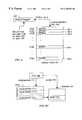
- FIG. 2is a block diagram of a RAID controller 102 that embodies the present invention.
- the RAID controller 102is coupled to the host 90 via one PCI bus 104 - 1 and to a disk array 106 that comprises the disk storage for a RAID system via a second PCI bus 104 - 2 .
- This bus connection arrangementis merely exemplary and can be implemented using equivalent configurations.
- the busses 104can be EIDE, IDE, SCSI or other bus types and the disk array 106 and the host 90 can share both busses in any combination. Also there might only be one bus 104 .
- the hostprovides requests/data 91 as described in reference to FIG. 1 .
- the host requests/data 91comprise disk I/O commands to be implemented by the RAID controller 102 .
- the RAID controllerwrites and reads data to/from the disk array 106 .
- the RAID controller 102includes a CPU 108 , a memory 110 , a coprocessor called the NorthBay ASIC (Application Specific Integrated Circuit) 112 and an NorthBay memory (NB-memory) 124 , which could be a Synchronous Dynamic RAM (SDRAM) or equivalent (static or dynamic) semiconductor memory.
- SDRAMSynchronous Dynamic RAM
- SDRAMSynchronous Dynamic RAM
- the CPU 108is ultimately responsible for operations of the RAID controller 102 , which it carries out with support from the NorthBay 112 .
- the CPU 108issues commands to the NorthBay 112 via scripts 109 , each of which includes multiple tasks 85 (FIG. 1 ).
- Each task 85directs the NorthBay 112 to generate parity for a particular data record in the NB-memory 124 and to store the parity in a particular location on the NB-memory 124 .
- the CPU 108moves data records between the disk array 106 and the NB-memory 124 depending on the host requests 91 .
- the data to be writtenis first stored by the CPU in the NB-memory 124 to enable the NorthBay 112 to generate parity, both of which values are subsequently stored in the disk array 106 . If the host request is for a read, the data to be read is copied from the disk array 106 to the NB-memory 124 by the CPU 108 and the NorthBay checks its correctness.
- Information 113 flowing from the NorthBay 112 to the CPU 108 during executionincludes interrupt requests 113 c , a NorthBay count (NB_cnt) 113 a and a NorthBay address (NB_addr) 113 b .
- the NorthBay 112issues an interrupt request 113 c every time it completes one of the scripted tasks 85 or an entire script 109 .
- the CPU 108reads the NB_cnt 113 a and NB_addr 113 b whenever it has time to service the NorthBay 112 .
- the NB_cnt value 113 aindicates the number of interrupts issued by the NorthBay since the CPU last serviced the NorthBay.
- the NB_addr value I 13 bgives the address of the task whose completion resulted in the NorthBay sending the most recent interrupt request 113 c.
- the NorthBay ASIC 112includes four major functions: two PCI-bus interfaces 104 - 1 , 104 - 2 ; an XOR-engine 116 ; and an N-B-memory controller 118 .
- the NorthBay 112also includes an interrupt counter register 120 and a dipstick register 122 .
- the completely independent PCI-bus interfaces 114 - 1 , 114 - 2communicate with other processors (e.g., the host 90 and the disk array 106 ) over the PCI busses 104 - 1 , 104 - 2 .
- Each PCI-bus 104is capable of moving data at a rate of 265 Mbytes per second between an external bus (not shown) and the embedded memory subsystem 124 .
- Each bus 104has its own Read-FIFO and Write-FIFO (not shown), which are used to maximize the data throughputs and the bus efficiency.
- the XOR engine 116performs “RAID Parity” computations and “Block-Move” operations (moving a block of memory content to another memory block) and may also be used to check the integrity of the data that is stored in the RAID storage system 106 .
- the XOR engine 116operates as slave to the CPU's master. All operations of the XOR engine 116 are in response to the scripts 109 generated by the CPU 108 . Each time it executes one of the tasks 85 specified in a script 109 or an entire script (this depends on its configuration) the XOR engine 116 issues an interrupt request 113 c , writes into the dipstick register 122 the address of the task whose completion triggered the interrupt into the dipstick register 122 and increments the interrupt counter 120 .
- the CPU 108Every time it is able to handle interrupt requests from the XOR engine 116 the CPU 108 reads the dipstick register 122 and reads and then resets the count in the interrupt counter 120 . In one embodiment the two reads are performed by the CPU 108 back to back to minimize the need to stall the XOR engine 116 during the reads. As it computes parity the XOR engine 116 reads and writes data in the NB-memory 124 under control of the NB-memory controller 118 .
- the NorthBay ASIC 112is memory an exemplary embodiment of the present invention. More generally, the present invention encompasses all computer mechanisms for handling interrupts wherein the interrupt handler does not service interrupts from the interrupt requester individually, as in a realtime system, but instead issues groups of tasks (e.g., scripts) to keep the interrupt requester as close to fully occupied as possible.
- groups of taskse.g., scripts
- Other exemplary systems in which the present invention can be implementedinclude the bottling and telecommunications systems mentioned above.
- FIG. 3is a block diagram of the memory 110 from FIG. 2 showing data structures and executables employed by one embodiment of the present invention.
- the memory 110represents any combination of a fast semiconductor memory or a slower magnetic or optical memory.
- programsare stored in non-volatile magnetic memory 110 and then executed in semiconductor memory 110 .
- the memory 10includes an operating system 130 , programs 140 and data 150 .
- the CPU 108executes programs 140 under control of the operating system 130 .
- the programs 140include a control program 142 that, among other things, determines how the CPU 108 responds to interrupt requests 113 c from the XOR engine 116 .
- Another program 140is the script composer 146 , which generates the NorthBay scripts 109 based on requests/data 91 from the host 90 .
- the data 150includes, among other items, an interrupt count 152 , an interrupt address 154 , an address table (AT) 156 , a last script header 158 , an interrupt mask 160 and a queue(s) 162 for requests/data 91 from the host 90 .
- the interrupt count (int_cnt) 152represents the number of interrupt requests 113 c issued by the NorthBay 112 since some past event known to the CPU 108 .
- This eventcan simply be the last time the CPU 108 serviced the NorthBay 112 , in which case the CPU 108 simply sets the int_cnt 152 equal to the latest value of the NB interrupt count (NB_cnt) 113 a .
- the eventcan be the last time the int_cnt 152 was reset by the CPU 108 , in which case the CPU sets the int_cnt 152 equal to the sum of the NB_cnt 113 a values received since that event.
- the interrupt address (int_addr) 154stores the NB address (NB_addr) 113 b read from the dipstick register 122 whenever that register is read by the CPU 108 .
- the dipstick register 122is completely rewritten after each NB interrupt request 113 c , meaning that the int_addr 154 represents only the source of the latest interrupt request.
- the address table 156is an ordered list of all of the tasks 85 sent by the CPU 108 to the NorthBay 112 for execution since some past event known to the CPU 108 . From this table 156 , given an interrupt count 152 or an interrupt address 154 , the CPU 108 can determine the tasks 85 that have been executed by the NorthBay 112 and therefore how many tasks 85 and/or scripts 109 remain to be executed by the NorthBay 112 . When the NorthBay 112 is in need of more data to process the script composer 146 generates additional scripts 109 reflecting the queued host requests 162 .
- One embodiment of the address table 156is described below with reference to FIG. 6 .
- the last script header 158is a local copy of the contents of a last-script-header-register (not shown) provided by the NorthBay 112 . Generally, when a new script is processed, the script starting-point is saved into the last-script-header-register. It is the responsibility of the CPU 108 to save in the last script header variable 158 the address in the last-script-header-register 232 , which the CPU 108 must then not reread.
- the interrupt mask 160is a set of bits that is ANDed with each interrupt request 113 c from the NorthBay 112 . When set to all zeroes the interrupt mask 160 completely blocks all interrupts.
- the interrupt mask 160can also be configured to allow the CPU 108 to receive notification of an interrupt request while masking off information pertaining to the particular interrupt address. Interrupt masking is permissible and even desirable in embodiments of the present invention, whose central tenet is that the CPU 108 does not respond to individual interrupts.
- the queue(s) 162hold requests/data 91 from the host 90 from which the CPU 108 formulates the scripts 109 issued to the NorthBay. Data structures defined in the NB-memory 124 , which supports operation of the XOR engine 116 , are now described with reference to FIG. 4 A.
- FIG. 4Ais a block diagram of the NB-memory 124 from FIG. 2 showing data structure defined therein in accordance with one embodiment of the present invention.
- the NB-memory 124includes scripts 170 , a queue 180 , source records 184 and parity words 186 .
- the scripts 170are stored versions of the scripts 109 sent to the NorthBay 112 by the CPU 108 .
- Each script 170includes multiple source pointers 172 (in the illustrated embodiment, there are eight source pointers 172 ), each of which holds the address of a source record 184 stored in the NB-memory 124 for which the XOR engine 116 is to compute parity.
- Each source record 184is copied to the NB-memory 124 from the disk array 106 by a process that is not described herein and that is not material to the present invention.
- a script 170also includes a destination pointer 174 , a control/count word 176 and a link list pointer 178 .
- the destination pointer 174holds the address of a NB-memory location in which the XOR engine 116 is to write the parity word 186 generated from the designated source records 184 .
- the source and destination pointers 172 , 174designate a starting memory address of the data block 184 to be processed.
- the control/count word 176contains 8 control bits and a 24-bit transfer count indicating the size (e.g,. in bytes) of the record 184 designated by the source pointers 172 .
- a 24-bit countcan be used to transfer up to 16 Mbytes of data per each individual script operation.
- the 8-control bitsinclude a SCRIPT_STOP bit 186 (FIG. 4B) that indicates whether, after completing the present script 170 , the XOR engine 116 is to continue processing another script 170 designated in the present script's link list address 178 .
- the queue 180includes a number of pointers 182 to scripts 170 received from the CPU 108 , which remain to be processed.
- all or part of the memory queue 180can be replaced with a script pointer FIFO queue implemented in hardware that can be directly accessed by the CPU.
- FIG. 4Cis a block diagram of a hardware FIFO implemented in the NorthBay 112 .
- the CPU 108can simply push a script pointer 111 i (FIG. 2) associated with a script 109 i onto the top of the FIFO - the script 109 i (stored as the script 170 i ) is executed by the XOR engine 116 as the script pointer 111 i moves to the bottom of the FIFO.
- Any number of chain operationsmay be programmed between the first and last scripts 170 in a chain (i.e., a chain can be as short as two chains and as long as a million claims or more ).
- the size of a script chainis only limited by the size of the NB-memory 124 .
- the XOR engine 116can compute a parity word 186 from all or a subset of the source records 184 designated by the chain of scripts 170 .
- Each chainhas its own source and destination addresses 172 , 174 , which respectively point to the source records 184 and the parity word 186 associated with the chain.
- An example of a script chainis now described with reference to FIG. 4 B.
- FIG. 4Bshows how scripts 170 can be chained using the aforementioned links 178 and control information 176 .
- the first of the chained scripts 170 - 1is designated by a respective script pointer 182 - 1 or the bottom entry of a script pointer FIFO 190 .
- the SCRIPT_STOP bit 186 - 1 of this script 170 - 1is set to logical “0”, which tells the XOR engine 116 that, after processing the source record designated by source address 8 ( 172 - 1 . 8 ) to continue processing the script 170 - 2 designated by the link 178 - 1 .
- the script 170 - 2is linked to the script 170 -n in a similar manner.
- the XOR engine 116finishes processing the script chain when it encounters in the script 170 -n a SCRIPT_STOP bit 186 -n set to logical “1”.
- script chainsinclude reducing the complexity of XOR engine operation 116 and simplifying the memory allocation effort. For example, using the LinkListPtrs 178 to build a script chain frees the XOR engine 116 from the need to allocate all related scripts in a linear memory space. Instead, scripts can be scattered around. Moreover, because scripts can be scattered around, a single script or one chain of a script chain can be stored in very few words (e.g., eleven words, assuming a script 170 formatted as shown in FIGS. 4 A and 4 B). A method by which the CPU 108 and the NorthBay ASIC cooperatively compute parity using the interrupt handing mechanisms of the present invention is now described in reference to FIG. 5 .
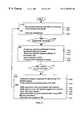
- FIG. 5shows a flow diagram of interrupt handling operations performed by the CPU 90 and the NorthBay (NB) ASIC 112 of FIG. 2 in accordance with the present invention.
- the order of operations shown in this diagramis merely exemplary; other arrangements of the operations are also possible and some steps can be omitted. Many of these operations have already been described above, so they are summarized herein only briefly.
- the operations attributed to the CPU 108are carried out by the control program 142 and the operations attributed to the NorthBay 112 are carried out by firmware that controls operation of the XOR engine 116 .
- the XOR engine 116is programmed for operation by the CPU control program 142 , which writes a script (or script chain) 109 generated by the script composer 146 (step 202 ) into a pre-determined script area 170 of the NB-memory 124 as already described ( 204 ).
- the control program 142then writes an associated script-pointer 111 to the queue 180 of stored script pointers 182 (FIGS. 4A, 4 B) or, in alternative embodiments, to the hardware FIFO queue.
- the XOR engine 116continually scans the queue 180 (or FIFO) for new script pointers 182 .
- the XOR engine 116fetches the eleven data words 172 , 174 , 176 , 178 composing the script 170 designated by the script pointer 182 , computes the parity 186 of the source records 184 designated by the source pointers 172 , and stores the parity 186 at the location designated by the destination pointer 174 ( 206 ). Note that as many as seven of the script pointers 172 may contain a null value, telling the XOR engine 116 that there is no associated source record 184 to retrieve.
- the XOR engine 116executes all scripts 170 in the chain ( 206 ) and stores the resulting parity word(s) 186 at the location(s) designated by the destination pointer(s) 174 .
- the NorthBay 112issues an interrupt request 113 c to the CPU 108 ( 216 ).
- the CPU 108is free to ignore or respond to this interrupt.
- the NorthBay 112increments the interrupt counter register 120 by one to indicate that a new interrupt has just occurred ( 212 ).
- the register 120is first tested for the overflow condition ( 210 ) and the NorthBay stalled if such an overflow has occurred).
- the interrupt counter 120continues to accumulate until the CPU control program 142 reads the interrupt counter register 120 , at which point the interrupt counter 120 is reset to zero.
- the NorthBay 112also stores into the dipstick register 122 the address of the task, script or script chain whose completion resulted in the generation of the interrupt 113 c ( 214 ).
- the dipstick register 122is a one-deep buffer, which is updated on each occurrence of a new interrupt 113 c . Unlike the interrupt counter register 120 , the dipstick register 122 is not cleared after it is read.
- the NorthBayproceeds to execute another script 170 ( 218 ) and the CPU 108 may or may not respond to the interrupt 113 c ( 220 ). If it is able to handle the interrupt 113 c or independently decides to service the NorthBay ( 220 -Y) the CPU 108 initiates an interrupt handling operation.
- the CPU 108reads the interrupt counter 120 and the dipstick register 122 and uses the values 113 a , 113 b stored therein to update its internal interrupt count and address 152 , 154 (FIG. 3) ( 226 , 228 ).
- the CPU 108must perform a back-to-back read where it reads the interrupt counter 120 first and then immediately thereafter reads the dipstick register 122 .
- the CPU 108clears the interrupt counter 120 after the reading step ( 230 ). Once it has updated its internal count and address 152 , 154 the CPU 108 determines how many tasks the NorthBay 112 has executed since the last time the CPU checked the NorthBay interrupt status ( 232 ).
- the CPU 108is able to make this determination because it generates the scripts 109 and controls the order of script 109 execution by the NorthBay 112 . Additional details regarding how the CPU 108 makes this determination is described with reference to FIG. 6 .
- the CPUuses its script generator 146 to generate new scripts for execution by the XOR engine 116 ( 234 ). For example, if the XOR engine 116 is about to run out of work, the CPU 108 will need to generate and send more scripts 109 .
- the NorthBay 112determines whether it needs to stall or can continue executing scripts ( 222 ). In one embodiment the NorthBay 112 will stall if it is about to trigger issue another interrupt request 113 c ( 224 ). If no interrupt request 113 c is pending the NorthBay 112 will continue processing scripts 109 while the CPU 108 accesses the registers 120 , 122 . Given the speed of register access by the CPU 108 , the stall situation is likely to occur infrequently. In fact, tests of an embodiment show that, under normal operating conditions, the NorthBay 112 stalls for this reason only about one percent of the time. Additional details are now provided regarding execution by the CPU 108 of the position determining step ( 232 ).
- the CPU 108can make the determination ( 232 ) according to at least one of three methods.
- the CPU 108retrieves from an ordered list of tasks sent to the NorthBay 112 (e.g., the address table 156 ) a task or script address ADDRi whose location i in the list corresponds to a known function of a current count representing tasks executed by the NorthBay 112 since a known event (e.g., the interrupt count 152 ) and the NB interrupt count 113 a .
- the known eventmight be the last the CPU reset the interrupt count 152 ).
- the CPU 108verifies that the retrieved task address ADDRi and the current interrupt address NB_int 113 b are identical. If they are not identical, then the CPU 108 can resolve the address/count mismatch using other control procedures 142 .
- the CPU 108searches in the ordered list (e.g., the address table 156 ) for the current interrupt address 113 b and verifies the current interrupt count 113 a by comparing it to a known function of the current count representing tasks executed by the NorthBay 112 since a known event (i.e., the interrupt count 152 ) and the index in the ordered list of the current address 113 b.
- the ordered liste.g., the address table 156
- the prior two methodsallow for cross-verification of NB counts 113 a and addresses 113 b by using both values 113 a , 113 b to reference the address table 156 .
- one of the NB values 113 a , 113 bmight not be available, or there might be no need to perform verification.
- yet another methodallows the CPU 108 to determine the execution status of the NorthBay 112 using just one of the NB count 113 a or address 113 b .
- the CPU 108determines from the current count 152 and the interrupt count 113 a what previously queued tasks have been executed by the interrupt generator.
- the interrupt generatori.e. the NorthBay 112
- the CPU 108determines from the position of the interrupt address 113 b in the ordered list (e.g., the address table 156 ) what previously queued tasks have been executed by the interrupt generator. The first method is now described with reference to FIG. 6 .
- FIG. 6shows one embodiment of the address table 156 including the addresses ADDR of the tasks 85 or scripts 109 , stored in order.
- This examplepresumes that the CPU 108 starts writing the task 85 or script 109 addresses ADDR at the base table address (AT[ 1 ]) every time the NB_cnt 113 a is reset to zero (i.e., the interrupt count 152 and the NB_cnt 113 a are identical).
- the CPU 108could accumulate the NB_cnt into the interrupt count 152 , which would, as a result, be able to serve as a direct index into a large table 156 .
- the CPU control program 142could determine the relative position of a completed task 85 or script 109 associated with an NB_cnt 113 a and NB_addr 133 b returned by the NorthBay using the following steps:
- step ( 4 )if step ( 4 ) is true, then the last task 85 completed by the NorthBay 112 is number NB_cnt out of the total number of tasks sent to the NorthBay 112 since the CPU 108 last reset the interrupt_count 152 and the NorthBay 112 reset the interrupt counter register 120 ;
- step ( 4 )if step ( 4 ) is not true, then there is a mismatch to be resolved between the NB_addr 113 b and the NB_cnt 113 a.
- embodiments of the present inventionprovide high throughput without imposing the stringent operating requirements regarding interrupt latency associated with realtime systems.
- a key advantage of the present inventionis that it allows high throughput to be achieved without requiring a powerful CPU 108 to service interrupts generated by a very powerful coprocessor, such as the NorthBay 112 .
- This arrangementcan be implemented in any system wherein a powerful co-processor needs to work on data received from a potentially overburdened master processor and wherein minimal interrupt latency is not a requirement.
Landscapes
- Engineering & Computer Science (AREA)
- Theoretical Computer Science (AREA)
- Physics & Mathematics (AREA)
- General Engineering & Computer Science (AREA)
- General Physics & Mathematics (AREA)
- Bus Control (AREA)
Abstract
Description
Claims (7)
Priority Applications (1)
| Application Number | Priority Date | Filing Date | Title |
|---|---|---|---|
| US09/186,043US6185652B1 (en) | 1998-11-03 | 1998-11-03 | Interrupt mechanism on NorthBay |
Applications Claiming Priority (1)
| Application Number | Priority Date | Filing Date | Title |
|---|---|---|---|
| US09/186,043US6185652B1 (en) | 1998-11-03 | 1998-11-03 | Interrupt mechanism on NorthBay |
Publications (1)
| Publication Number | Publication Date |
|---|---|
| US6185652B1true US6185652B1 (en) | 2001-02-06 |
Family
ID=22683425
Family Applications (1)
| Application Number | Title | Priority Date | Filing Date |
|---|---|---|---|
| US09/186,043Expired - LifetimeUS6185652B1 (en) | 1998-11-03 | 1998-11-03 | Interrupt mechanism on NorthBay |
Country Status (1)
| Country | Link |
|---|---|
| US (1) | US6185652B1 (en) |
Cited By (49)
| Publication number | Priority date | Publication date | Assignee | Title |
|---|---|---|---|---|
| US20010056520A1 (en)* | 2000-06-15 | 2001-12-27 | Mcbryde Lee | Data management architecture |
| US20030065733A1 (en)* | 2001-09-28 | 2003-04-03 | Pecone Victor Key | Modular architecture for a network storage controller |
| US20030065836A1 (en)* | 2001-09-28 | 2003-04-03 | Pecone Victor Key | Controller data sharing using a modular DMA architecture |
| US6553443B1 (en)* | 1999-09-28 | 2003-04-22 | Legerity, Inc. | Method and apparatus for prioritizing interrupts in a communication system |
| US20030158933A1 (en)* | 2002-01-10 | 2003-08-21 | Hubbert Smith | Failover clustering based on input/output processors |
| US20040177126A1 (en)* | 2003-02-18 | 2004-09-09 | Chaparral Network Storage, Inc. | Broadcast bridge apparatus for transferring data to redundant memory subsystems in a storage controller |
| US20040186931A1 (en)* | 2001-11-09 | 2004-09-23 | Gene Maine | Transferring data using direct memory access |
| US20050071515A1 (en)* | 2003-09-30 | 2005-03-31 | International Business Machines Corporation | Method and apparatus for counting instruction execution and data accesses |
| US20050071609A1 (en)* | 2003-09-30 | 2005-03-31 | International Business Machines Corporation | Method and apparatus to autonomically take an exception on specified instructions |
| US20050071610A1 (en)* | 2003-09-30 | 2005-03-31 | International Business Machines Corporation | Method and apparatus for debug support for individual instructions and memory locations |
| US20050071817A1 (en)* | 2003-09-30 | 2005-03-31 | International Business Machines Corporation | Method and apparatus for counting execution of specific instructions and accesses to specific data locations |
| US20050071816A1 (en)* | 2003-09-30 | 2005-03-31 | International Business Machines Corporation | Method and apparatus to autonomically count instruction execution for applications |
| US20050070265A1 (en)* | 2003-09-29 | 2005-03-31 | Nokia Corporation | Method, terminal device and system for remote initiation of network applications within mobile communication environment |
| US20050071608A1 (en)* | 2003-09-30 | 2005-03-31 | International Business Machines Corporation | Method and apparatus for selectively counting instructions and data accesses |
| US20050071822A1 (en)* | 2003-09-30 | 2005-03-31 | International Business Machines Corporation | Method and apparatus for counting instruction and memory location ranges |
| US20050071611A1 (en)* | 2003-09-30 | 2005-03-31 | International Business Machines Corporation | Method and apparatus for counting data accesses and instruction executions that exceed a threshold |
| US20050071821A1 (en)* | 2003-09-30 | 2005-03-31 | International Business Machines Corporation | Method and apparatus to autonomically select instructions for selective counting |
| US20050081107A1 (en)* | 2003-10-09 | 2005-04-14 | International Business Machines Corporation | Method and system for autonomic execution path selection in an application |
| US20050081019A1 (en)* | 2003-10-09 | 2005-04-14 | International Business Machines Corporation | Method and system for autonomic monitoring of semaphore operation in an application |
| US6889278B1 (en)* | 2001-04-04 | 2005-05-03 | Cisco Technology, Inc. | Method and apparatus for fast acknowledgement and efficient servicing of interrupt sources coupled to high latency paths |
| US20050102557A1 (en)* | 2001-09-28 | 2005-05-12 | Dot Hill Systems Corporation | Apparatus and method for adopting an orphan I/O port in a redundant storage controller |
| US20050144521A1 (en)* | 2003-12-10 | 2005-06-30 | International Business Machines Corporation | For PPRC backup systems |
| US20050154813A1 (en)* | 2004-01-14 | 2005-07-14 | International Business Machines Corporation | Method and apparatus for counting interrupts by type |
| US20050154812A1 (en)* | 2004-01-14 | 2005-07-14 | International Business Machines Corporation | Method and apparatus for providing pre and post handlers for recording events |
| US20050154811A1 (en)* | 2004-01-14 | 2005-07-14 | International Business Machines Corporation | Method and apparatus for qualifying collection of performance monitoring events by types of interrupt when interrupt occurs |
| US20050273651A1 (en)* | 2004-05-18 | 2005-12-08 | Aristos Logic Corporation | Method of implementing XOR based raid algorithms |
| US20050283554A1 (en)* | 2004-06-22 | 2005-12-22 | General Electric Company | Computer system and method for queuing interrupt messages in a device coupled to a parallel communication bus |
| US20060106982A1 (en)* | 2001-09-28 | 2006-05-18 | Dot Hill Systems Corporation | Certified memory-to-memory data transfer between active-active raid controllers |
| US20060161707A1 (en)* | 2005-01-20 | 2006-07-20 | Dot Hill Systems Corporation | Method for efficient inter-processor communication in an active-active RAID system using PCI-express links |
| US20060161709A1 (en)* | 2005-01-20 | 2006-07-20 | Dot Hill Systems Corporation | Safe message transfers on PCI-Express link from RAID controller to receiver-programmable window of partner RAID controller CPU memory |
| US20060277347A1 (en)* | 2001-09-28 | 2006-12-07 | Dot Hill Systems Corporation | RAID system for performing efficient mirrored posted-write operations |
| US20070079040A1 (en)* | 2003-07-22 | 2007-04-05 | Park Hee-Chul | Interrupt signal processing circuit for sending interrupt requests to a computer system |
| US20080005470A1 (en)* | 2006-06-30 | 2008-01-03 | Dot Hill Systems Corporation | System and method for sharing sata drives in active-active raid controller system |
| US20080189687A1 (en)* | 2004-01-14 | 2008-08-07 | International Business Machines Corporation | Method and Apparatus for Maintaining Performance Monitoring Structures in a Page Table for Use in Monitoring Performance of a Computer Program |
| US20080201616A1 (en)* | 2007-02-20 | 2008-08-21 | Dot Hill Systems Corporation | Redundant storage controller system with enhanced failure analysis capability |
| US20080216091A1 (en)* | 2004-01-14 | 2008-09-04 | International Business Machines Corporation | Autonomic Method and Apparatus for Hardware Assist for Patching Code |
| US20080288952A1 (en)* | 2007-05-18 | 2008-11-20 | Takahito Seki | Processing apparatus and device control unit |
| US20080320194A1 (en)* | 2007-06-20 | 2008-12-25 | Microsoft Corporation | Monitored notification facility for reducing inter-process / inter-partition interrupts |
| US7546483B1 (en)* | 2005-10-18 | 2009-06-09 | Nvidia Corporation | Offloading RAID functions to a graphics coprocessor |
| US7574587B2 (en) | 2004-01-14 | 2009-08-11 | International Business Machines Corporation | Method and apparatus for autonomically initiating measurement of secondary metrics based on hardware counter values for primary metrics |
| US20110078341A1 (en)* | 2008-05-27 | 2011-03-31 | Sandisk Il Ltd. | Method of monitoring host activity |
| US8171457B2 (en) | 2004-03-22 | 2012-05-01 | International Business Machines Corporation | Autonomic test case feedback using hardware assistance for data coverage |
| US20140156986A1 (en)* | 2012-11-30 | 2014-06-05 | Inventec Corporation | Motherboard in a server |
| US20150019279A1 (en)* | 2012-02-14 | 2015-01-15 | Krones Ag | Filling installation and computer-implemented method for the automatic establishment of a current and individual work list |
| US20150347178A1 (en)* | 2014-05-30 | 2015-12-03 | Apple Inc. | Method and apparatus for activity based execution scheduling |
| US20160119683A1 (en)* | 2000-09-29 | 2016-04-28 | Rovi Technologies Corporation | User controlled multi-device media-on-demand system |
| US10162727B2 (en) | 2014-05-30 | 2018-12-25 | Apple Inc. | Activity tracing diagnostic systems and methods |
| US10467162B2 (en) | 2017-03-31 | 2019-11-05 | Hewlett Packard Enterprise Development Lp | Interrupt based on a last interrupt request indicator and a work acknowledgement |
| US20230046788A1 (en)* | 2021-08-16 | 2023-02-16 | Capital One Services, Llc | Systems and methods for resetting an authentication counter |
Citations (4)
| Publication number | Priority date | Publication date | Assignee | Title |
|---|---|---|---|---|
| US5805883A (en)* | 1994-03-08 | 1998-09-08 | Fujitsu Limited | Interrupt process distributing system |
| US5892957A (en)* | 1995-03-31 | 1999-04-06 | Sun Microsystems, Inc. | Method and apparatus for interrupt communication in packet-switched microprocessor-based computer system |
| US5928348A (en)* | 1997-03-19 | 1999-07-27 | Mitsubishi Denki Kabushiki Kaisha | Method of processing interrupt requests and information processing apparatus using the method |
| US5974440A (en)* | 1996-03-25 | 1999-10-26 | Texas Instruments Incorporated | Microprocessor with circuits, systems, and methods for interrupt handling during virtual task operation |
- 1998
- 1998-11-03USUS09/186,043patent/US6185652B1/ennot_activeExpired - Lifetime
Patent Citations (4)
| Publication number | Priority date | Publication date | Assignee | Title |
|---|---|---|---|---|
| US5805883A (en)* | 1994-03-08 | 1998-09-08 | Fujitsu Limited | Interrupt process distributing system |
| US5892957A (en)* | 1995-03-31 | 1999-04-06 | Sun Microsystems, Inc. | Method and apparatus for interrupt communication in packet-switched microprocessor-based computer system |
| US5974440A (en)* | 1996-03-25 | 1999-10-26 | Texas Instruments Incorporated | Microprocessor with circuits, systems, and methods for interrupt handling during virtual task operation |
| US5928348A (en)* | 1997-03-19 | 1999-07-27 | Mitsubishi Denki Kabushiki Kaisha | Method of processing interrupt requests and information processing apparatus using the method |
Cited By (94)
| Publication number | Priority date | Publication date | Assignee | Title |
|---|---|---|---|---|
| US6553443B1 (en)* | 1999-09-28 | 2003-04-22 | Legerity, Inc. | Method and apparatus for prioritizing interrupts in a communication system |
| US7127668B2 (en)* | 2000-06-15 | 2006-10-24 | Datadirect Networks, Inc. | Data management architecture |
| US20010056520A1 (en)* | 2000-06-15 | 2001-12-27 | Mcbryde Lee | Data management architecture |
| US20160119683A1 (en)* | 2000-09-29 | 2016-04-28 | Rovi Technologies Corporation | User controlled multi-device media-on-demand system |
| US6889278B1 (en)* | 2001-04-04 | 2005-05-03 | Cisco Technology, Inc. | Method and apparatus for fast acknowledgement and efficient servicing of interrupt sources coupled to high latency paths |
| US7146448B2 (en) | 2001-09-28 | 2006-12-05 | Dot Hill Systems Corporation | Apparatus and method for adopting an orphan I/O port in a redundant storage controller |
| US20060277347A1 (en)* | 2001-09-28 | 2006-12-07 | Dot Hill Systems Corporation | RAID system for performing efficient mirrored posted-write operations |
| GB2396726A (en)* | 2001-09-28 | 2004-06-30 | Chaparral Network Storage Inc | Modular architecture for a network storage controller |
| US7062591B2 (en) | 2001-09-28 | 2006-06-13 | Dot Hill Systems Corp. | Controller data sharing using a modular DMA architecture |
| US20030065836A1 (en)* | 2001-09-28 | 2003-04-03 | Pecone Victor Key | Controller data sharing using a modular DMA architecture |
| US7340555B2 (en) | 2001-09-28 | 2008-03-04 | Dot Hill Systems Corporation | RAID system for performing efficient mirrored posted-write operations |
| US7437493B2 (en) | 2001-09-28 | 2008-10-14 | Dot Hill Systems Corp. | Modular architecture for a network storage controller |
| WO2003036493A1 (en)* | 2001-09-28 | 2003-05-01 | Chaparral Network Storage, Inc. | Modular architecture for a network storage controller |
| US7536495B2 (en) | 2001-09-28 | 2009-05-19 | Dot Hill Systems Corporation | Certified memory-to-memory data transfer between active-active raid controllers |
| US20050102557A1 (en)* | 2001-09-28 | 2005-05-12 | Dot Hill Systems Corporation | Apparatus and method for adopting an orphan I/O port in a redundant storage controller |
| US20060282701A1 (en)* | 2001-09-28 | 2006-12-14 | Dot Hill Systems Corporation | Method for adopting an orphan i/o port in a redundant storage controller |
| US20060106982A1 (en)* | 2001-09-28 | 2006-05-18 | Dot Hill Systems Corporation | Certified memory-to-memory data transfer between active-active raid controllers |
| US7558897B2 (en) | 2001-09-28 | 2009-07-07 | Dot Hill Systems Corporation | Method for adopting an orphan I/O port in a redundant storage controller |
| GB2396726B (en)* | 2001-09-28 | 2006-04-12 | Chaparral Network Storage Inc | Modular architecture for a network storage controller |
| US20030065733A1 (en)* | 2001-09-28 | 2003-04-03 | Pecone Victor Key | Modular architecture for a network storage controller |
| US7380115B2 (en) | 2001-11-09 | 2008-05-27 | Dot Hill Systems Corp. | Transferring data using direct memory access |
| US20040186931A1 (en)* | 2001-11-09 | 2004-09-23 | Gene Maine | Transferring data using direct memory access |
| US20030158933A1 (en)* | 2002-01-10 | 2003-08-21 | Hubbert Smith | Failover clustering based on input/output processors |
| US7143227B2 (en) | 2003-02-18 | 2006-11-28 | Dot Hill Systems Corporation | Broadcast bridge apparatus for transferring data to redundant memory subsystems in a storage controller |
| US20040177126A1 (en)* | 2003-02-18 | 2004-09-09 | Chaparral Network Storage, Inc. | Broadcast bridge apparatus for transferring data to redundant memory subsystems in a storage controller |
| US20070079040A1 (en)* | 2003-07-22 | 2007-04-05 | Park Hee-Chul | Interrupt signal processing circuit for sending interrupt requests to a computer system |
| US7752368B2 (en)* | 2003-07-22 | 2010-07-06 | Samsung Electronics Co., Ltd. | Interrupt signal processing circuit for sending interrupt requests to a computer system |
| US20050070265A1 (en)* | 2003-09-29 | 2005-03-31 | Nokia Corporation | Method, terminal device and system for remote initiation of network applications within mobile communication environment |
| US20050071611A1 (en)* | 2003-09-30 | 2005-03-31 | International Business Machines Corporation | Method and apparatus for counting data accesses and instruction executions that exceed a threshold |
| US20050071609A1 (en)* | 2003-09-30 | 2005-03-31 | International Business Machines Corporation | Method and apparatus to autonomically take an exception on specified instructions |
| US7395527B2 (en) | 2003-09-30 | 2008-07-01 | International Business Machines Corporation | Method and apparatus for counting instruction execution and data accesses |
| US20080141005A1 (en)* | 2003-09-30 | 2008-06-12 | Dewitt Jr Jimmie Earl | Method and apparatus for counting instruction execution and data accesses |
| US7937691B2 (en) | 2003-09-30 | 2011-05-03 | International Business Machines Corporation | Method and apparatus for counting execution of specific instructions and accesses to specific data locations |
| US8689190B2 (en) | 2003-09-30 | 2014-04-01 | International Business Machines Corporation | Counting instruction execution and data accesses |
| US20050071515A1 (en)* | 2003-09-30 | 2005-03-31 | International Business Machines Corporation | Method and apparatus for counting instruction execution and data accesses |
| US7373637B2 (en) | 2003-09-30 | 2008-05-13 | International Business Machines Corporation | Method and apparatus for counting instruction and memory location ranges |
| US8255880B2 (en) | 2003-09-30 | 2012-08-28 | International Business Machines Corporation | Counting instruction and memory location ranges |
| US20080235495A1 (en)* | 2003-09-30 | 2008-09-25 | International Business Machines Corporation | Method and Apparatus for Counting Instruction and Memory Location Ranges |
| US20050071822A1 (en)* | 2003-09-30 | 2005-03-31 | International Business Machines Corporation | Method and apparatus for counting instruction and memory location ranges |
| US20050071608A1 (en)* | 2003-09-30 | 2005-03-31 | International Business Machines Corporation | Method and apparatus for selectively counting instructions and data accesses |
| US20050071816A1 (en)* | 2003-09-30 | 2005-03-31 | International Business Machines Corporation | Method and apparatus to autonomically count instruction execution for applications |
| US20050071817A1 (en)* | 2003-09-30 | 2005-03-31 | International Business Machines Corporation | Method and apparatus for counting execution of specific instructions and accesses to specific data locations |
| US20050071610A1 (en)* | 2003-09-30 | 2005-03-31 | International Business Machines Corporation | Method and apparatus for debug support for individual instructions and memory locations |
| US20050071821A1 (en)* | 2003-09-30 | 2005-03-31 | International Business Machines Corporation | Method and apparatus to autonomically select instructions for selective counting |
| US20080244239A1 (en)* | 2003-10-09 | 2008-10-02 | International Business Machines Corporation | Method and System for Autonomic Monitoring of Semaphore Operations in an Application |
| US7421681B2 (en) | 2003-10-09 | 2008-09-02 | International Business Machines Corporation | Method and system for autonomic monitoring of semaphore operation in an application |
| US20050081107A1 (en)* | 2003-10-09 | 2005-04-14 | International Business Machines Corporation | Method and system for autonomic execution path selection in an application |
| US8042102B2 (en) | 2003-10-09 | 2011-10-18 | International Business Machines Corporation | Method and system for autonomic monitoring of semaphore operations in an application |
| US8381037B2 (en) | 2003-10-09 | 2013-02-19 | International Business Machines Corporation | Method and system for autonomic execution path selection in an application |
| US20050081019A1 (en)* | 2003-10-09 | 2005-04-14 | International Business Machines Corporation | Method and system for autonomic monitoring of semaphore operation in an application |
| US20050144521A1 (en)* | 2003-12-10 | 2005-06-30 | International Business Machines Corporation | For PPRC backup systems |
| US7171583B2 (en) | 2003-12-10 | 2007-01-30 | International Business Machines Corporation | For PPRC backup systems |
| US7895382B2 (en) | 2004-01-14 | 2011-02-22 | International Business Machines Corporation | Method and apparatus for qualifying collection of performance monitoring events by types of interrupt when interrupt occurs |
| US7082486B2 (en)* | 2004-01-14 | 2006-07-25 | International Business Machines Corporation | Method and apparatus for counting interrupts by type |
| CN100382061C (en)* | 2004-01-14 | 2008-04-16 | 国际商业机器公司 | Method and apparatus for counting interrupts by type |
| US20050154813A1 (en)* | 2004-01-14 | 2005-07-14 | International Business Machines Corporation | Method and apparatus for counting interrupts by type |
| US8141099B2 (en) | 2004-01-14 | 2012-03-20 | International Business Machines Corporation | Autonomic method and apparatus for hardware assist for patching code |
| US8782664B2 (en) | 2004-01-14 | 2014-07-15 | International Business Machines Corporation | Autonomic hardware assist for patching code |
| US20110106994A1 (en)* | 2004-01-14 | 2011-05-05 | International Business Machines Corporation | Method and apparatus for qualifying collection of performance monitoring events by types of interrupt when interrupt occurs |
| US8191049B2 (en) | 2004-01-14 | 2012-05-29 | International Business Machines Corporation | Method and apparatus for maintaining performance monitoring structures in a page table for use in monitoring performance of a computer program |
| US20080189687A1 (en)* | 2004-01-14 | 2008-08-07 | International Business Machines Corporation | Method and Apparatus for Maintaining Performance Monitoring Structures in a Page Table for Use in Monitoring Performance of a Computer Program |
| US8615619B2 (en) | 2004-01-14 | 2013-12-24 | International Business Machines Corporation | Qualifying collection of performance monitoring events by types of interrupt when interrupt occurs |
| US20080216091A1 (en)* | 2004-01-14 | 2008-09-04 | International Business Machines Corporation | Autonomic Method and Apparatus for Hardware Assist for Patching Code |
| US20050154812A1 (en)* | 2004-01-14 | 2005-07-14 | International Business Machines Corporation | Method and apparatus for providing pre and post handlers for recording events |
| US20050154811A1 (en)* | 2004-01-14 | 2005-07-14 | International Business Machines Corporation | Method and apparatus for qualifying collection of performance monitoring events by types of interrupt when interrupt occurs |
| US7574587B2 (en) | 2004-01-14 | 2009-08-11 | International Business Machines Corporation | Method and apparatus for autonomically initiating measurement of secondary metrics based on hardware counter values for primary metrics |
| US8171457B2 (en) | 2004-03-22 | 2012-05-01 | International Business Machines Corporation | Autonomic test case feedback using hardware assistance for data coverage |
| US7827469B2 (en)* | 2004-05-18 | 2010-11-02 | Adpt Corporation | Method of implementing XOR based RAID algorithms |
| US20050273651A1 (en)* | 2004-05-18 | 2005-12-08 | Aristos Logic Corporation | Method of implementing XOR based raid algorithms |
| US20090094479A1 (en)* | 2004-05-18 | 2009-04-09 | Sanjay Subbarao | Method of implementing xor based raid algorithms |
| US20050283554A1 (en)* | 2004-06-22 | 2005-12-22 | General Electric Company | Computer system and method for queuing interrupt messages in a device coupled to a parallel communication bus |
| US20060161709A1 (en)* | 2005-01-20 | 2006-07-20 | Dot Hill Systems Corporation | Safe message transfers on PCI-Express link from RAID controller to receiver-programmable window of partner RAID controller CPU memory |
| US7543096B2 (en) | 2005-01-20 | 2009-06-02 | Dot Hill Systems Corporation | Safe message transfers on PCI-Express link from RAID controller to receiver-programmable window of partner RAID controller CPU memory |
| US20060161707A1 (en)* | 2005-01-20 | 2006-07-20 | Dot Hill Systems Corporation | Method for efficient inter-processor communication in an active-active RAID system using PCI-express links |
| US7315911B2 (en) | 2005-01-20 | 2008-01-01 | Dot Hill Systems Corporation | Method for efficient inter-processor communication in an active-active RAID system using PCI-express links |
| US7546483B1 (en)* | 2005-10-18 | 2009-06-09 | Nvidia Corporation | Offloading RAID functions to a graphics coprocessor |
| US7536508B2 (en) | 2006-06-30 | 2009-05-19 | Dot Hill Systems Corporation | System and method for sharing SATA drives in active-active RAID controller system |
| US20080005470A1 (en)* | 2006-06-30 | 2008-01-03 | Dot Hill Systems Corporation | System and method for sharing sata drives in active-active raid controller system |
| US20080201616A1 (en)* | 2007-02-20 | 2008-08-21 | Dot Hill Systems Corporation | Redundant storage controller system with enhanced failure analysis capability |
| US7681089B2 (en) | 2007-02-20 | 2010-03-16 | Dot Hill Systems Corporation | Redundant storage controller system with enhanced failure analysis capability |
| US20080288952A1 (en)* | 2007-05-18 | 2008-11-20 | Takahito Seki | Processing apparatus and device control unit |
| US7913009B2 (en) | 2007-06-20 | 2011-03-22 | Microsoft Corporation | Monitored notification facility for reducing inter-process/inter-partition interrupts |
| US20080320194A1 (en)* | 2007-06-20 | 2008-12-25 | Microsoft Corporation | Monitored notification facility for reducing inter-process / inter-partition interrupts |
| USRE45908E1 (en) | 2008-05-27 | 2016-03-01 | Sandisk Il Ltd. | Method of monitoring host activity |
| US20110078341A1 (en)* | 2008-05-27 | 2011-03-31 | Sandisk Il Ltd. | Method of monitoring host activity |
| US8230128B2 (en)* | 2008-05-27 | 2012-07-24 | Sandisk Il Ltd. | Monitoring host activity using an interrupt |
| US20150019279A1 (en)* | 2012-02-14 | 2015-01-15 | Krones Ag | Filling installation and computer-implemented method for the automatic establishment of a current and individual work list |
| US20140156986A1 (en)* | 2012-11-30 | 2014-06-05 | Inventec Corporation | Motherboard in a server |
| US9189245B2 (en)* | 2012-11-30 | 2015-11-17 | Inventec (Pudong) Technology Corporation | Motherboard in a server |
| US20150347178A1 (en)* | 2014-05-30 | 2015-12-03 | Apple Inc. | Method and apparatus for activity based execution scheduling |
| US9665398B2 (en)* | 2014-05-30 | 2017-05-30 | Apple Inc. | Method and apparatus for activity based execution scheduling |
| US10162727B2 (en) | 2014-05-30 | 2018-12-25 | Apple Inc. | Activity tracing diagnostic systems and methods |
| US10467162B2 (en) | 2017-03-31 | 2019-11-05 | Hewlett Packard Enterprise Development Lp | Interrupt based on a last interrupt request indicator and a work acknowledgement |
| US20230046788A1 (en)* | 2021-08-16 | 2023-02-16 | Capital One Services, Llc | Systems and methods for resetting an authentication counter |
Similar Documents
| Publication | Publication Date | Title |
|---|---|---|
| US6185652B1 (en) | Interrupt mechanism on NorthBay | |
| US5224215A (en) | Message queue processing among cooperative processors having significant speed differences | |
| US6772310B2 (en) | Method and apparatus for zeroing a transfer buffer memory as a background task | |
| US7702835B2 (en) | Tagged interrupt forwarding | |
| KR970011213B1 (en) | Queuing Method of Post-Write Disk Write Operations with Error Handling | |
| US5313585A (en) | Disk drive array with request fragmentation | |
| EP0768600B1 (en) | Locked exchange Fifo | |
| US7389364B2 (en) | Apparatus and method for direct memory access in a hub-based memory system | |
| US5802345A (en) | Computer system with a reduced number of command end interrupts from auxiliary memory unit and method of reducing the number of command end interrupts | |
| US5694581A (en) | Concurrent disk array management system implemented with CPU executable extension | |
| US6324599B1 (en) | Computer system and method for tracking DMA transferred data within a read-ahead local buffer without interrupting the host processor | |
| US6760814B2 (en) | Methods and apparatus for loading CRC values into a CRC cache in a storage controller | |
| US5996046A (en) | Parity generation system for generating new parity using old data in temporary storage without accessing main disk storage of disk drive | |
| US5682551A (en) | System for checking the acceptance of I/O request to an interface using software visible instruction which provides a status signal and performs operations in response thereto | |
| US20060230240A1 (en) | Inter-processor communication method using a shared cache memory in a storage system | |
| US20100037226A1 (en) | Grouping and dispatching scans in cache | |
| US20080177914A1 (en) | Hardware support system for accelerated disk I/O | |
| WO2003043254A9 (en) | Transferring data using direct memory access | |
| Varma et al. | Destage algorithms for disk arrays with nonvolatile caches | |
| US5909574A (en) | Computing system with exception handler and method of handling exceptions in a computing system | |
| JP4053208B2 (en) | Disk array controller | |
| CN1099080C (en) | Using intelligent bridges with PICO-code to improve interrupt response | |
| US5386560A (en) | Execution of page data transfer by PT processors and issuing of split start and test instructions by CPUs coordinated by queued tokens | |
| US8533163B2 (en) | Database offload processing | |
| US6801954B1 (en) | Method and apparatus to concurrently operate on multiple data movement transactions in a disk array subsystem |
Legal Events
| Date | Code | Title | Description |
|---|---|---|---|
| AS | Assignment | Owner name:MYLEX CORPORATION, CALIFORNIA Free format text:ASSIGNMENT OF ASSIGNORS INTEREST;ASSIGNORS:SHEK, EDDE TANG TIN;STUBBS, ROBERT E.;REEL/FRAME:009727/0515 Effective date:19990114 | |
| STCF | Information on status: patent grant | Free format text:PATENTED CASE | |
| FEPP | Fee payment procedure | Free format text:PAYOR NUMBER ASSIGNED (ORIGINAL EVENT CODE: ASPN); ENTITY STATUS OF PATENT OWNER: LARGE ENTITY | |
| FEPP | Fee payment procedure | Free format text:PAT HOLDER NO LONGER CLAIMS SMALL ENTITY STATUS, ENTITY STATUS SET TO UNDISCOUNTED (ORIGINAL EVENT CODE: STOL); ENTITY STATUS OF PATENT OWNER: LARGE ENTITY | |
| REFU | Refund | Free format text:REFUND - SURCHARGE, PETITION TO ACCEPT PYMT AFTER EXP, UNINTENTIONAL (ORIGINAL EVENT CODE: R2551); ENTITY STATUS OF PATENT OWNER: LARGE ENTITY | |
| AS | Assignment | Owner name:LSI LOGIC CORPORATION, CALIFORNIA Free format text:ASSIGNMENT OF ASSIGNORS INTEREST;ASSIGNORS:INTERNATIONAL BUSINESS MACHINES CORPORATION;LSI LOGIC CORPORATION;REEL/FRAME:014990/0688 Effective date:20020910 | |
| FPAY | Fee payment | Year of fee payment:4 | |
| FEPP | Fee payment procedure | Free format text:PAYER NUMBER DE-ASSIGNED (ORIGINAL EVENT CODE: RMPN); ENTITY STATUS OF PATENT OWNER: LARGE ENTITY Free format text:PAYOR NUMBER ASSIGNED (ORIGINAL EVENT CODE: ASPN); ENTITY STATUS OF PATENT OWNER: LARGE ENTITY | |
| FPAY | Fee payment | Year of fee payment:8 | |
| FPAY | Fee payment | Year of fee payment:12 | |
| AS | Assignment | Owner name:DEUTSCHE BANK AG NEW YORK BRANCH, AS COLLATERAL AG Free format text:PATENT SECURITY AGREEMENT;ASSIGNORS:LSI CORPORATION;AGERE SYSTEMS LLC;REEL/FRAME:032856/0031 Effective date:20140506 | |
| AS | Assignment | Owner name:LSI CORPORATION, CALIFORNIA Free format text:CHANGE OF NAME;ASSIGNOR:LSI LOGIC CORPORATION;REEL/FRAME:033102/0270 Effective date:20070406 | |
| AS | Assignment | Owner name:AVAGO TECHNOLOGIES GENERAL IP (SINGAPORE) PTE. LTD Free format text:ASSIGNMENT OF ASSIGNORS INTEREST;ASSIGNOR:LSI CORPORATION;REEL/FRAME:035390/0388 Effective date:20140814 | |
| AS | Assignment | Owner name:LSI CORPORATION, CALIFORNIA Free format text:TERMINATION AND RELEASE OF SECURITY INTEREST IN PATENT RIGHTS (RELEASES RF 032856-0031);ASSIGNOR:DEUTSCHE BANK AG NEW YORK BRANCH, AS COLLATERAL AGENT;REEL/FRAME:037684/0039 Effective date:20160201 Owner name:AGERE SYSTEMS LLC, PENNSYLVANIA Free format text:TERMINATION AND RELEASE OF SECURITY INTEREST IN PATENT RIGHTS (RELEASES RF 032856-0031);ASSIGNOR:DEUTSCHE BANK AG NEW YORK BRANCH, AS COLLATERAL AGENT;REEL/FRAME:037684/0039 Effective date:20160201 | |
| AS | Assignment | Owner name:BANK OF AMERICA, N.A., AS COLLATERAL AGENT, NORTH CAROLINA Free format text:PATENT SECURITY AGREEMENT;ASSIGNOR:AVAGO TECHNOLOGIES GENERAL IP (SINGAPORE) PTE. LTD.;REEL/FRAME:037808/0001 Effective date:20160201 Owner name:BANK OF AMERICA, N.A., AS COLLATERAL AGENT, NORTH Free format text:PATENT SECURITY AGREEMENT;ASSIGNOR:AVAGO TECHNOLOGIES GENERAL IP (SINGAPORE) PTE. LTD.;REEL/FRAME:037808/0001 Effective date:20160201 | |
| AS | Assignment | Owner name:AVAGO TECHNOLOGIES GENERAL IP (SINGAPORE) PTE. LTD., SINGAPORE Free format text:TERMINATION AND RELEASE OF SECURITY INTEREST IN PATENTS;ASSIGNOR:BANK OF AMERICA, N.A., AS COLLATERAL AGENT;REEL/FRAME:041710/0001 Effective date:20170119 Owner name:AVAGO TECHNOLOGIES GENERAL IP (SINGAPORE) PTE. LTD Free format text:TERMINATION AND RELEASE OF SECURITY INTEREST IN PATENTS;ASSIGNOR:BANK OF AMERICA, N.A., AS COLLATERAL AGENT;REEL/FRAME:041710/0001 Effective date:20170119 | |
| AS | Assignment | Owner name:AVAGO TECHNOLOGIES INTERNATIONAL SALES PTE. LIMITE Free format text:ASSIGNMENT OF ASSIGNORS INTEREST;ASSIGNOR:AVAGO TECHNOLOGIES GENERAL IP (SINGAPORE) PTE. LTD.;REEL/FRAME:047022/0620 Effective date:20180509 | |
| AS | Assignment | Owner name:AVAGO TECHNOLOGIES INTERNATIONAL SALES PTE. LIMITE Free format text:CORRECTIVE ASSIGNMENT TO CORRECT THE NATURE OF CONVEYANCE AND EFFECTIVE DATE PREVIOUSLY RECORDED ON REEL 047022 FRAME 0620. ASSIGNOR(S) HEREBY CONFIRMS THE MERGER;ASSIGNOR:AVAGO TECHNOLOGIES GENERAL IP (SINGAPORE) PTE. LTD.;REEL/FRAME:047185/0643 Effective date:20180509 | |
| AS | Assignment | Owner name:AVAGO TECHNOLOGIES INTERNATIONAL SALES PTE. LIMITE Free format text:CORRECTIVE ASSIGNMENT TO CORRECT THE EFFECTIVE DATE PREVIOUSLY RECORDED ON REEL 047185 FRAME 0643. ASSIGNOR(S) HEREBY CONFIRMS THE MERGER;ASSIGNOR:AVAGO TECHNOLOGIES GENERAL IP (SINGAPORE) PTE. LTD.;REEL/FRAME:047476/0845 Effective date:20180905 | |
| AS | Assignment | Owner name:AVAGO TECHNOLOGIES INTERNATIONAL SALES PTE. LIMITE Free format text:CORRECTIVE ASSIGNMENT TO CORRECT THE EFFECTIVE DATE OF MERGER PREVIOUSLY RECORDED AT REEL: 047185 FRAME: 0643. ASSIGNOR(S) HEREBY CONFIRMS THE CORRECTIVE MERGER;ASSIGNOR:AVAGO TECHNOLOGIES GENERAL IP (SINGAPORE) PTE. LTD.;REEL/FRAME:047959/0296 Effective date:20180905 |