US6185458B1 - Reduced energy self test operation in a defibrillator - Google Patents
Reduced energy self test operation in a defibrillatorDownload PDFInfo
- Publication number
- US6185458B1 US6185458B1US09/302,983US30298399AUS6185458B1US 6185458 B1US6185458 B1US 6185458B1US 30298399 AUS30298399 AUS 30298399AUS 6185458 B1US6185458 B1US 6185458B1
- Authority
- US
- United States
- Prior art keywords
- voltage
- test
- defibrillator
- current
- self test
- Prior art date
- Legal status (The legal status is an assumption and is not a legal conclusion. Google has not performed a legal analysis and makes no representation as to the accuracy of the status listed.)
- Expired - Lifetime
Links
- 238000012360testing methodMethods0.000titleclaimsabstractdescription182
- 239000003990capacitorSubstances0.000claimsdescription56
- 238000004146energy storageMethods0.000claimsdescription47
- 238000000034methodMethods0.000claimsdescription30
- 238000012544monitoring processMethods0.000claimsdescription7
- 230000035939shockEffects0.000claimsdescription7
- 238000012358sourcingMethods0.000claims6
- 238000005259measurementMethods0.000description8
- 238000010998test methodMethods0.000description7
- 208000003663ventricular fibrillationDiseases0.000description6
- 230000002051biphasic effectEffects0.000description5
- 230000008901benefitEffects0.000description4
- 238000010586diagramMethods0.000description3
- 230000000694effectsEffects0.000description3
- 238000005265energy consumptionMethods0.000description2
- 230000004044responseEffects0.000description2
- 230000033764rhythmic processEffects0.000description2
- 239000000126substanceSubstances0.000description2
- 230000001360synchronised effectEffects0.000description2
- YAJFESRMRIIXCL-UHFFFAOYSA-NCC(CN=O)C(C)(C)CChemical compoundCC(CN=O)C(C)(C)CYAJFESRMRIIXCL-UHFFFAOYSA-N0.000description1
- XUIMIQQOPSSXEZ-UHFFFAOYSA-NSiliconChemical compound[Si]XUIMIQQOPSSXEZ-UHFFFAOYSA-N0.000description1
- 206010049418Sudden Cardiac DeathDiseases0.000description1
- LWZFANDGMFTDAV-BURFUSLBSA-N[(2r)-2-[(2r,3r,4s)-3,4-dihydroxyoxolan-2-yl]-2-hydroxyethyl] dodecanoateChemical compoundCCCCCCCCCCCC(=O)OC[C@@H](O)[C@H]1OC[C@H](O)[C@H]1OLWZFANDGMFTDAV-BURFUSLBSA-N0.000description1
- 230000002159abnormal effectEffects0.000description1
- 239000008280bloodSubstances0.000description1
- 210000004369bloodAnatomy0.000description1
- 230000000747cardiac effectEffects0.000description1
- 230000008859changeEffects0.000description1
- 230000000739chaotic effectEffects0.000description1
- 230000008878couplingEffects0.000description1
- 238000010168coupling processMethods0.000description1
- 238000005859coupling reactionMethods0.000description1
- 238000001514detection methodMethods0.000description1
- 238000001827electrotherapyMethods0.000description1
- 239000000835fiberSubstances0.000description1
- 230000004118muscle contractionEffects0.000description1
- 210000004165myocardiumAnatomy0.000description1
- 210000001087myotubuleAnatomy0.000description1
- 210000000056organAnatomy0.000description1
- 230000000737periodic effectEffects0.000description1
- 238000005086pumpingMethods0.000description1
- 238000011076safety testMethods0.000description1
- 229910052710siliconInorganic materials0.000description1
- 239000010703siliconSubstances0.000description1
- 235000011067sorbitan monolaureateNutrition0.000description1
- 238000012795verificationMethods0.000description1
Images


Classifications
- A—HUMAN NECESSITIES
- A61—MEDICAL OR VETERINARY SCIENCE; HYGIENE
- A61N—ELECTROTHERAPY; MAGNETOTHERAPY; RADIATION THERAPY; ULTRASOUND THERAPY
- A61N1/00—Electrotherapy; Circuits therefor
- A61N1/18—Applying electric currents by contact electrodes
- A61N1/32—Applying electric currents by contact electrodes alternating or intermittent currents
- A61N1/38—Applying electric currents by contact electrodes alternating or intermittent currents for producing shock effects
- A61N1/39—Heart defibrillators
- A61N1/3925—Monitoring; Protecting
- A61N1/3937—Monitoring output parameters
Definitions
- This inventionrelates to electrotherapy circuits and in particular to a defibrillator having an improved self test operation that requires less energy.
- Electro-chemical activity within a human heartnormally causes the heart muscle fibers to contract and relax in a synchronized manner that results in the effective pumping of blood from the ventricles to the body's vital organs. Sudden cardiac death is often caused by ventricular fibrillation (VF) in which abnormal electrical activity within the heart causes the individual muscle fibers to contract in an unsynchronized and chaotic way.
- VFventricular fibrillation
- the only effective treatment for VFis electrical defibrillation in which an electrical shock is applied to the heart to allow the heart's electro-chemical system to re-synchronize itself. Once organized electrical activity is restored, synchronized muscle contractions usually follow, leading to the restoration of cardiac rhythm.
- AEDsautomatic external defibrillators
- AEDsmay be used by first responders and lay people.
- AEDsmay remain unused for long periods of time and yet must be ready to operate reliably in an emergency situation.
- AEDsemploy a self test operation that is conducted at regular intervals.
- the Heartstream Forerunner® AEDemploys a self test system that generates self test operations automatically in response to a predetermined schedule.
- the self test operationtypically includes a number of different system checks including functional, calibration, and safety tests to verify that the defibrillator's components and operation are within predetermined specifications.
- the high voltage (HV) circuitis a critical component of the defibrillator that provides the defibrillation pulse. Verification of the proper functioning of the defibrillator is a typical part of any self test operation.
- HVhigh voltage
- Such self testsmay be done periodically or in response to changes in the defibrillator environment such as the ambient temperature as described in U.S. Pat. No. 5,868,792, issued Feb. 9, 1999, “Environment-Response Method for Maintaining Electronic Devices Such As An External Defibrillator”, issued Feb. 9, 1999, to Ochs et al. which is incorporated herein by reference.
- U.S. Pat. No. 5,800,460“Method for Performing Self-Test In A Defibrillator”, issued Sep. 1, 1998, to Powers et al., describes in detail the operation of a defibrillator self test system which is incorporated herein by reference.
- An energy storage capacitoris twice charged to full voltage and discharged, first to functionally verify operation of the HV circuit under combined maximum voltage and current conditions and second to calibrate the HV circuit to ensure that the amount of energy delivered in the defibrillation pulse is within specification limits.
- the test loadis resistance typically in the range of 10 to 20 ohms.
- U.S. Pat. No. 5,873,893“Method and Apparatus for Verifying the Integrity of an Output Circuit Before and During Application of a Defibrillation Pulse”, to Sullivan et al. describes an external defibrillator capable of testing the high voltage output circuit for open and shorted switches by monitoring the energy storage capacitor voltage.
- the high voltage circuitthe well known H-bridge configuration, is tested first by sequentially turning on each of the switches in each leg of the H-bridge while the energy storage capacitor is charged up to a test voltage. No current conducting paths should appear through the H bridge. Next, current conducting paths through each side of the H bridge are created for a brief time and the energy storage capacitor voltage is monitored.
- the energy storage capacitor voltageshould drop by a predetermined amount for each discharge. While it is mentioned by Sullivan et al. that the test voltage may be less than the maximum voltage to reduce energy consumption, there is no teaching on how the test voltage may differ between the open and short circuit tests to allow for full testing of HV circuit at both maximum current and maximum voltage levels.
- a defibrillator having a self test operation requiring reduced energyis provided.
- HV circuitswill typically include an energy storage capacitor, a high voltage charger to charge the energy storage capacitor, and an HV switch which operates to deliver a defibrillation pulse to a patient in a desired polarity and for a desired pulse duration using the energy from the energy storage capacitor.
- the HV switchis an H-bridge circuit which is well known in the art to commutate the voltage from the energy storage capacitor to the patient first in one polarity and then in the other polarity to form a biphasic defibrillation pulse.
- a voltage stress testis conducted to ensure that the dielectric withstand voltage of the various components of the HV switch are adequate at the maximum voltage level.
- the components of the HV switchare silicon controlled rectifiers (SCRs) and insulated gate bipolar transistors (IGBTs).
- the voltage stress testis conducted by imposing the maximum voltage level which would be incurred during normal use, typically 2,000 volts, across each of the components in the HV switch and monitoring either for any current flow through each component or a significant voltage drop in the energy storage capacitor voltage.
- the current stress testis conducted to ensure that the current handling capability of each component is adequate to source the maximum current level which would be incurred during normal use, typically 100 amperes, to the test load.
- the test loadis preferably a low impedance that less than the lowest impedance of the expected range of impedances spanning 20 to 200 ohms.
- the maximum voltage level and the maximum current levelmay be chosen to exceed the operating voltage level and operating current level which are the maximum values that occur during normal operation of the defibrillator in order to more fully stress the components of the HV switch and charging circuitry.
- the present inventionallows for testing of the HV circuit at the maximum current level and at the maximum voltage level with substantially reduced energy consumption and battery drain during the self test of the HV circuit from that of the prior art.
- the current stress testis conducted at substantially lower energy levels by coupling a low impedance test load across the H bridge in place of a patient impedance and with the energy storage capacitor charged to a partial voltage.
- the voltage stress testis done at the maximum voltage level and on its own consumes no energy because there is no path for the current to flow under normal conditions and is.
- the charge stored in the energy storage capacitor, which is still at the maximum voltage level following the voltage stress test,can then be used for other portions of the self test operation including generation of the calibration pulse.
- One feature of the present inventionis to provide a self test method for a defibrillator.
- a further feature of the present inventionis to provide a method of reduced energy self test in a defibrillator.
- a further feature of the present inventionis to provide a method of reduced energy self test in a defibrillator that provides for testing at maximum voltage and maximum current levels.
- Another feature of the present inventionis to provide an external defibrillator having a reduced energy self test circuit.
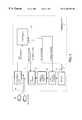
- FIG. 1is a block diagram of a defibrillator having an HV circuit that is tested according to the present invention
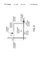
- FIG. 2is a schematic diagram of the HV switch portion of the HV circuit of FIG. 1;
- FIG. 3is a graph of voltage versus current of a combined voltage stress and current stress test as conducted according to prior art self test methods
- FIG. 4is a graph of voltage versus current showing the separate voltage stress and current stress tests as conducted according the self test method of the present invention
- FIG. 5is a graph of voltage versus current showing an alternative embodiment of the present invention in which the maximum current and voltage exceed the voltage and current of the operating region;
- FIG. 6is a flow chart of the self test method according to the present invention.
- FIG. 1is a block diagram of a defibrillator 10 that incorporates a method of reduced energy self test according to the present invention.
- a pair of electrodes 12are coupled across the chest of a patient (not shown).
- the pair of electrodes 12are coupled to an ECG front end 18 which filters, amplifies, and digitizes the ECG signal from the patient to obtain ECG information which is provided to a controller 26 .
- a defibrillation pulsemay be delivered to the patient by the defibrillator 10 upon detection of a shockable rhythm such as ventricular fibrillation (VF) that is detected in the ECG information by the controller 26 running a shock advisory algorithm.
- VFventricular fibrillation
- An HV circuit 14is coupled to the electrodes 12 and delivers a defibrillation pulse in a desired polarity and duration across the electrodes 12 .
- the defibrillation pulseis a biphasic truncated exponential waveform.
- the HV circuit 14contains an HV switch 16 that is coupled to the pair of electrodes 12 , an energy storage circuit 20 coupled to the HV switch 16 , and a high voltage charger 22 for charging the energy storage circuit 20 to the desired charge level.
- the HV switch 16is constructed as an H bridge as explained in more detail below.
- the energy storage circuit 20is coupled to the HV switch 16 to provide the high voltage, high current waveform necessary to develop the defibrillation pulse.
- the energy storage circuit 20typically consists of at least one capacitor with a capacitance value in the range of 100 to 200 microFarads (uF) and which is charged to over 2000 volts at the maximum voltage.
- the high voltage charger 22converts the relatively low battery voltage, typically 12 volts, from a battery 24 to the relatively high voltage levels required to charge the energy storage circuit 20 .
- the controller 26operates to control the functions of the defibrillator 10 including the self test operation according to the present invention.
- the HV switch 16develops the defibrillation pulse responsive to a switch control signal from the controller 26 in the desired polarity and pulse duration.
- the voltage of the energy storage circuit 20is controlled through via the charge control signal to the high voltage charger 22 from the controller 26 .
- a current signal from the HV switch 16 and a voltage signal from the energy storage circuit 20may be fed back to the controller 26 which evaluates the results of the self test operation.
- FIG. 2there is shown a simplified schematic drawing of the energy storage circuit 20 and the HV switch 16 .
- a capacitor 40 in the energy storage circuit 20provides for storage of the energy required for the defibrillation pulse.
- the capacitor 40is charged to a voltage level determined by the controller 26 .
- the voltage levelis measured using a voltage measurement circuit 42 that provides the voltage signal back to the controller 26 .
- the voltage measurement circuit 42preferably consists of a voltage divider network and analog to digital converter that provides the voltage signal in the form of digital measurement values to the controller 26 . If the voltage signal from the energy storage circuit 20 has a value within specification limits based on the charge control signal to the high voltage charger, then the high voltage charger 22 is determined to be functioning normally.
- SCRs 50 - 56form an H bridge circuit coupled between the capacitor 40 and ground.
- the H bridge circuitunder the control of the controller 26 which generates the switch control signals A-F, operates to couple the voltage from the capacitor 40 to the patient in the desired polarity and for the desired time duration.
- the SCRs 50 - 56are controlled via control inputs A-D which each receive the switch control signals A-D from the controller 26 .
- the voltage from the capacitor 40is coupled to the H bridge circuit via a series resistor 60 and a parallel combination of an inductor 62 and clamping diode 64 .
- the inductor 62has an inductance value chosen to limit the rate of current change through the H bridge in order to allow current limiting circuits (not shown) time to engage before excessive current flows through the H bridge.
- the series resistor 60is in the range of 5 ohms in the preferred embodiment.
- Pull down resistors 66 and 68ensure that the cathode ends of the SCRs 50 and 52 are near ground potential when the SCRs 50 and 52 are off and the IGBT 70 is on. This ground potential is also the normal operating state of the HV switch 16 when the energy storage circuit 20 is charged up and ready to deliver the defibrillation pulse.
- the resistors 66 and 68have resistance values that are high enough, for example in the 10,000 ohm range that they draw only nominal current when either of the SCRs 50 or 52 is on.
- a snubber circuit 82consisting of a resistor 84 in series with a capacitor 86 , is coupled in shunt across the SCR 54 .
- the snubber circuit 82is provided to prevent the inadvertent triggering of the SCR 54 responsive to a rapid rise in voltage between the anode and cathode, commonly known as dV/dt trigger.
- the ability of the snubber circuit 82 to prevent dV/dt triggermay be effectively tested during the voltage stress test by providing a rapidly changing voltage across the SCR 54 such as by turning on one of the SCRs 50 and 52 with the switch 80 a-b in the short position.
- IGBT 70Interposed between the H bridge and ground is an insulated gate bipolar transistor (IGBT) 70 having a control input F.
- the control input Freceives a portion of the switch control signal from the controller 26 .
- the IGBT 70operates as a switch to interrupt the flow of current through the H bridge to allow the SCRs 50 - 56 to turn off.
- a current measurement circuit 74measures the current flowing through the H bridge by measuring the voltage across a resistor 72 which is interposed between the capacitor 40 and ground.
- the current measurement circuit 74may alternatively consist of an over-current detector in the form of a comparator configured to provide an over-current signal when the current through the H bridge exceeds a predetermined trip level.
- a disarm circuit 79consisting of an SCR 76 with a control input E in series with a load resistor 78 operates in parallel with the H-bridge circuit.
- the control input Ereceives a portion E of the switch control signal from the controller 26 .
- the disarm circuitoperates to safely discharge the capacitor 40 through the load resistor 78 and the resistor 60 during normal operation of the defibrillator 10 when a defibrillation pulse to the patient is not needed.
- the disarm circuitmay also be used in the self test mode with the load resistor 78 and the resistor 60 operating as the test load to receive the calibration pulse generated by turning on the SCR 78 using the switch control signal E from the controller 26 .
- the discharge time of the calibration pulseis measured by the controller 26 by monitoring the voltage or current signal in order to control for variations in the charge voltage and capacitance value of the capacitor 40 . Using the measured discharge times, the controller 26 may then compensate for variations in voltages and component values in order to deliver a defibrillation pulse to the patient within desired specification limits. Applying the disarm shock through the SCR 76 will also apply the maximum voltage level to the collector of the IGBT 70 which should be in the off state.
- a switch 80 a-bwhich operates as a ganged double pole, double throw switch with an upper and lower position controlled by a control input G.
- the control input Greceives a switch control signal G from the controller 26 .
- the switch 80 a-bcouples the HV switch 16 to the electrodes 12 in order to deliver a defibrillation shock to the patient.
- the switch 80 a-bcouples the H bridge to a short circuit.
- the short circuitis an electrical connection such as a short piece of wire with a resistance substantially close to zero ohms and the resistor 60 operates as the test load.
- the switch 80 a-bcould couple the H bridge to a test load with the desired test load resistance.
- the switch 80 a-bcouples the H bridge to an external resistor (not shown) with a value chosen such that the series combination of the external resistor and the resistor 60 equal the desired test load resistance.
- the capacitor 40is charged to a desired voltage level and the switch 80 a-b is placed in the lower position to couple the HV switch 16 to the pair of electrodes 12 .
- the IGBT 70is then turned on followed by SCRs 50 and 56 to begin the first phase of the defibrillation pulse that is delivered to the patient. After a desired period of time, the IGBT 70 is turned off followed by the SCRs 50 and 56 to end the first phase. To begin the second phase, the IGBT 70 is again turned on, followed by the SCRs 52 and 54 . After a desired period of time, the IGBT 70 is again turned off followed by the SCRs 52 and 54 . If a no-shock decision is reached by the controller 26 after the capacitor 40 had been charged, the disarm circuit could be activated by turning on SCR 76 to safely discharge the capacitor 40 through the load resistor 78 .
- the self test operation of the defibrillator 10a series of tests of the H bridge are conducted in order to ensure its proper function within specified limits. Such tests include current stress, voltage stress, and calibration.
- the current stress testis conducted at the maximum current level and the voltage stress test is conducted at the maximum voltage level.
- the self test operation according to the prior artwill be explained in more detail below according to FIG. 3 .
- the self test operation according to the present inventionwill be explained in more detail below according to FIGS. 4 and 6.
- the maximum voltage and current levelsmay exceed the current and voltage levels encountered during normal operation of the defibrillator 10 as explained in more detail below according to FIG. 5 .
- FIG. 3is a graph of voltage versus current for the voltage and current stress tests and calibration tests as conducted according to the prior art.
- the current stress and voltage stress testsoccur simultaneously as the maximum current and maximum voltage conditions are met with discharge into a 20 ohm load which includes 10 ohms of series resistance and 10 ohms test load.
- This first testcorresponds to location 100 on the graph of FIG. 1 with a maximum voltage of 2,000 volts and a maximum current of 100 amperes (A).
- Ccapacitance (in Farads) of the capacitor
- Vis the charge voltage across the capacitor
- the energy storage capacitoris again charged up to maximum voltage and a calibration pulse is discharged into the test load corresponding to location 102 on the graph.
- Other known resistor valuesmay be substituted for the test load resistance corresponding to locations 104 and 106 so that the discharge time for each of the known load resistances may be measured.
- the charge voltage and the capacitance of the energy storage capacitorcan be determined and then controlled for by compensation in the pulse duration of the defibrillation pulse in order to deliver a desired amount of energy to the patient. While this self test method according to the prior art is effective, it results in two full discharges of the capacitor totaling 400 j using the energy value from the above example, resulting in substantial battery drain for each self test operation.
- FIG. 4is a graph of voltage versus current for the voltage and current stress tests and calibration tests as conducted according to the present invention.
- the current stress and voltage stress testsoccur separately, along with the calibration portion.
- the capacitor 40is charged to the maximum voltage only once for the voltage stress test which occurs at location 200 on the graph. Since no current flows for a normal voltage stress test, no energy is dissipated and the capacitor 40 remains at the maximum voltage level. Calibration pulses may then be generated and their discharge times measured for calibration purposes at locations 202 and 204 on the graph.
- the capacitor 40is charged to the partial voltage, for example to 500 volts, to obtain the desired level of current for the current stress test of 100 A with a test load resistance of 5 ohms corresponding to location 206 on the graph.
- the capacitor 40is storing only ⁇ fraction (1/16) ⁇ the amount of energy of the maximum voltage level of 2,000 volts, resulting in substantially reduced energy requirements for self test from that of the prior art.
- FIG. 5is a graph of voltage versus current for the voltage and current stress tests and calibration tests as conducted according to an alternative embodiment of the present invention.
- An operating region 206is a region which defines as the range of voltages and currents that may be expected during the normal operation of the defibrillator 10 when delivering a defibrillation pulse.
- the maximum voltage and maximum currentinstead of coinciding with the operation voltage and current as in the preferred embodiment, are now chosen to exceed the operating voltage and current.
- the maximum currentis chosen to exceed the operating current by ten percent and the maximum voltage is chosen to exceed the operating voltage by ten percent.
- the benefit of exceeding the operating voltage and current during the voltage stress test and current stress testis achieving an added margin of safety in ensuring the proper function of the components of the HV switch 16 , energy storage circuit 20 , and the high voltage charger 22 .
- the benefits of present inventionare realized in the alternative embodiment by obtaining a wider margin of safety in the self test operation while substantially reducing the energy requirements.
- the capacitor 40is charged to maximum voltage level only once for the voltage stress test which occurs at location 208 on the graph. Since no current flows for a normal voltage stress test, no energy is dissipated and the capacitor 40 remains at maximum voltage.
- the calibration pulsesmay then be generated and their discharge times measured for calibration purposes preferably at locations within or along the border of the operating region 206 .
- the capacitor 40is charged to the partial voltage, for example to 550 volts, to obtain the desired level of current for the current stress test of 100 A corresponding to location 206 on the graph.
- the capacitor 40is storing only ⁇ fraction (1/16) ⁇ the amount of energy of its maximum voltage level of 2,200 volts, still resulting in substantially reduced energy requirements for self test from that of the prior art.
- step 300labeled CHARGE CAPACITOR TO MAXIMUM VOLTAGE
- the capacitor 40is charged by the high voltage charger 22 to the maximum voltage level.
- the maximum voltageis approximately 2,000 volts.
- the voltage level across the capacitor 40is measured by the voltage measurement circuit 42 and fed back to the controller 26 as the voltage signal. If the voltage signal is within specification limits, the operation of the high voltage charger 22 and energy storage circuit 20 are determined to be normal by the controller 26 .
- step 302labeled CONDUCT VOLTAGE STRESS TEST, the SCRs 50 - 56 are exposed to the maximum voltage present in the capacitor 40 .
- the switch 80 a-bis placed in the upper position to short the cathodes of the SCRs 50 and 52 together and the IGBT 70 is turned on.
- the SCRs 50 and 52form the top half of the H bridge and are tested first.
- the pull down resistors 66 and 68operate to pull the junction to ground potential to impose the maximum voltage across each of the SCRs 50 and 52 presently in their off state and appearing as an open circuit.
- Leakage current through the H bridge circuitis monitored during the voltage stress test.
- the voltage signal from the voltage measurement circuit 42may alternatively be monitored for voltage drop in place of the current signal. If the SCRs 50 and 52 leak only negligible amounts of current, then they are deemed to have passed the voltage stress test. Next, one or both of the SCRs 50 and 52 is turned on, now imposing the maximum voltage across each of the SCRs 54 and 56 which form a bottom half of the H bridge and appear as open circuits. If the SCRs 54 and 56 leak only negligible amounts of current, they are deemed to have passed the voltage stress test. A failure of the voltage stress test occurs when any of the SCRs 50 - 56 , or any other element of the H bridge, breaks down and begins to pass substantial amounts of current.
- step 304 labeled GENERATE CALIBRATION SHOCK TO TEST LOADthe capacitor 40 is still fully charged from the step 302 and can provide the calibration pulse to the test load.
- the test loadconsists of the load resistor 78 in series with the resistor 60 in the disarm circuit.
- the calibration pulseis delivered by turning on the SCR 76 which completely discharged the capacitor 40 before turning off again.
- the test loadmay consist of an external load resistor put in place of the pair of electrodes 12 which is delivered by turning on the IGBT 70 and either the SCRs 50 and 56 or the SCRs 52 and 54 .
- the discharge time across the test loadwhich is a known resistance such as 10 ohms is measured by the controller 26 in order to calibrate the amount of energy delivered to the patient in the defibrillation pulse.
- step 306labeled CHARGE CAPACITOR TO PARTIAL VOLTAGE
- the capacitor 40is charged to a partial voltage which is a fraction of the maximum voltage and is chosen so that the high voltage circuit can source the maximum current level to the short circuit given the series resistance of the resistor 60 .
- the switch 80 a-bis moved into the shorting position, effectively shorting the HV switch 16 , with only the resistor 60 in the current path to obtain the desired test load resistance.
- the capacitor 40would be charged to 500 volts.
- step 308labeled CONDUCT CURRENT STRESS TEST, the current handling capability of the H bridge is tested at the maximum current level. Similar to the sequence for generating a biphasic defibrillation pulse, the current test pulse is created in both polarities. IGBT 70 is turned on followed by SCRs 50 and 56 during the first phase to source the maximum current through the short circuit test load. After a desired time duration, IGBT 70 is turned off followed by SCRs 50 and 56 to end the first phase. The IGBT 70 is again turned on, followed by SCRs 52 and 54 during the second phase to source the maximum current through the short circuit. After a desired time duration, IGBT 70 is again turned off followed by SCRs 52 and 54 .
- IGBT 70is turned on followed by SCRs 50 and 54 during the first phase to source the maximum current through one side of the H bridge circuit which acts as a short circuit. After a desired time duration, IGBT 70 is turned off followed by SCRs 50 and 54 . The IGBT 70 is again turned on, followed by SCRs 52 and 56 during the second phase to secure the maximum current through the other side of the H bridge circuit which acts as a short circuit. After a desired time duration, IGBT 70 is again turned off followed by SCRs 52 and 56 .
- the time duration of the first phaseis preferably very short to minimize the energy lost from the capacitor 40 .
- the capacitor 40is then charged back up to the partial voltage level. Since only a portion of the energy stored in the capacitor 40 has been discharged during the first phase depending on its duration, charging the capacitor 40 for the second phase should require a fraction of the energy needed for the first phase.
- a failure of the current stress testoccurs when the H bridge fails to source the maximum current level for the desired time duration, either in the first or second phases.
- An advantage of the current stress test according to the present inventionis that the H bridge is exercised in the same manner as it would be during the delivery of a defibrillation pulse under normal operation to obtain a more realistic test.
- the same pairs of SCRseither SCRs 50 and 56 or SCRs 52 and 54 are used to deliver the first and second phases of the current stress test as well as the first and second phases of the biphasic defibrillation pulse.
- the self test methodmay be readily applied to any configuration of the HV switch 16 , such as a simpler switch topology that supports only monophasic defibrillation pulses.
- the energy storage circuit 20may also be constructed using multiple capacitors.
- the current stress testconsisting of steps 306 and 308 may be conducted before the voltage stress test and calibration consisting of steps 300 - 304 during the self test operation. Therefore, the scope of the present invention should be determined by the following claims.
Landscapes
- Health & Medical Sciences (AREA)
- Cardiology (AREA)
- Heart & Thoracic Surgery (AREA)
- Engineering & Computer Science (AREA)
- Biomedical Technology (AREA)
- Nuclear Medicine, Radiotherapy & Molecular Imaging (AREA)
- Radiology & Medical Imaging (AREA)
- Life Sciences & Earth Sciences (AREA)
- Animal Behavior & Ethology (AREA)
- General Health & Medical Sciences (AREA)
- Public Health (AREA)
- Veterinary Medicine (AREA)
- Electrotherapy Devices (AREA)
Abstract
Description
Claims (31)
Priority Applications (1)
| Application Number | Priority Date | Filing Date | Title |
|---|---|---|---|
| US09/302,983US6185458B1 (en) | 1999-04-30 | 1999-04-30 | Reduced energy self test operation in a defibrillator |
Applications Claiming Priority (1)
| Application Number | Priority Date | Filing Date | Title |
|---|---|---|---|
| US09/302,983US6185458B1 (en) | 1999-04-30 | 1999-04-30 | Reduced energy self test operation in a defibrillator |
Publications (1)
| Publication Number | Publication Date |
|---|---|
| US6185458B1true US6185458B1 (en) | 2001-02-06 |
Family
ID=23170083
Family Applications (1)
| Application Number | Title | Priority Date | Filing Date |
|---|---|---|---|
| US09/302,983Expired - LifetimeUS6185458B1 (en) | 1999-04-30 | 1999-04-30 | Reduced energy self test operation in a defibrillator |
Country Status (1)
| Country | Link |
|---|---|
| US (1) | US6185458B1 (en) |
Cited By (22)
| Publication number | Priority date | Publication date | Assignee | Title |
|---|---|---|---|---|
| US20030171780A1 (en)* | 2002-03-11 | 2003-09-11 | Medtronic Physio-Control Manufacturing Corp. | Method and apparatus for self-test of defibrillation and pacing circuits including a patient isolation switch |
| US20030204225A1 (en)* | 2002-04-26 | 2003-10-30 | Medtronic, Inc. | Detection of possible failure of capacitive elements in an implantable medical device |
| US20060064140A1 (en)* | 2001-01-30 | 2006-03-23 | Whitehurst Todd K | Methods and systems for stimulating a trigeminal nerve to treat a psychiatric disorder |
| US20060064131A1 (en)* | 2000-02-04 | 2006-03-23 | Freeman Gary A | User interface for defibrillator for use by persons with limited training and experience |
| US7096062B2 (en) | 2002-03-11 | 2006-08-22 | Medtronic Physio-Control Manufacturing Corp. | Method for self-test of defibrillation and pacing circuits including a patient isolation switch |
| US20070265612A1 (en)* | 2006-05-10 | 2007-11-15 | Sherwood Services Ag | System and method for reducing leakage current in an electrosurgical generator |
| US20070296421A1 (en)* | 2006-06-07 | 2007-12-27 | Nec Electronics Corporation | Voltage drop measurement circuit |
| US20080046015A1 (en)* | 2004-09-30 | 2008-02-21 | Zoll Medical Corporation | Integrated Resuscitation |
| US20080077189A1 (en)* | 2006-09-22 | 2008-03-27 | Cameron Health, Inc. | Method and device for implantable cardiac stimulus device lead impedance measurement |
| US20100134090A1 (en)* | 2008-09-23 | 2010-06-03 | Stephen Burns | Stun Device Testing Apparatus and Methods |
| US7736237B2 (en) | 2002-03-01 | 2010-06-15 | Aegis Industries, Inc. | Electromuscular incapacitation device and methods |
| US20100160839A1 (en)* | 2005-09-14 | 2010-06-24 | Freeman Gary A | Synchronization of Repetitive Therapeutic Interventions |
| US7930023B2 (en) | 2001-09-21 | 2011-04-19 | Defibtech, Llc | Automatic external defibrillator with active status indicator |
| WO2013134763A3 (en)* | 2012-03-09 | 2014-04-17 | Enteromedics Inc. | Safety features for use in medical devices |
| WO2014097035A1 (en) | 2012-12-17 | 2014-06-26 | Koninklijke Philips N.V. | Adaptive self-testing and stress analysis of medical devices |
| WO2016115965A1 (en)* | 2015-01-20 | 2016-07-28 | 深圳市科曼医疗设备有限公司 | Self-checking system and method for discharge circuit of defibrillation monitor |
| US10322060B2 (en) | 2013-09-25 | 2019-06-18 | Zoll Medical Corporation | Mobile device control |
| US11108227B2 (en)* | 2017-04-04 | 2021-08-31 | Semiconductor Components Industries, Llc | Methods and apparatus for a battery |
| US11305128B1 (en)* | 2019-07-09 | 2022-04-19 | Avive Solutions, Inc. | Defibrillator discharge testing |
| US20230333954A1 (en)* | 2016-01-08 | 2023-10-19 | Zoll Medical Corporation | Patient assurance system and method |
| US11944582B2 (en) | 2013-04-30 | 2024-04-02 | Zoll Medical Corporation | Compression depth monitor with variable release velocity feedback |
| US12214211B2 (en) | 2020-09-04 | 2025-02-04 | Zoll Medical Corporation | Medical treatment system with companion device |
Citations (9)
| Publication number | Priority date | Publication date | Assignee | Title |
|---|---|---|---|---|
| US4328808A (en) | 1980-10-09 | 1982-05-11 | Hewlett-Packard Company | Defibrillator with means for determining patient impedance and delivered energy |
| US5111813A (en) | 1990-05-18 | 1992-05-12 | Hewlett-Packard Company | Defibrillation employing an impedance-corrected delivered energy |
| US5285779A (en) | 1992-03-27 | 1994-02-15 | Hewlett-Packard Company | Method and apparatus for a cardiac defibrillator high voltage charging circuit |
| US5384544A (en) | 1993-03-02 | 1995-01-24 | Hewlett-Packard Corporation | Method and apparatus for calibrating the energy output of a defibrillator |
| US5395394A (en) | 1993-06-17 | 1995-03-07 | Hewlett-Packard Corporation | Defibrillator with a high voltage solid state relay |
| US5591213A (en) | 1993-05-18 | 1997-01-07 | Heartstream, Inc. | Defibrillator system condition indictator |
| US5716381A (en)* | 1996-08-06 | 1998-02-10 | Pacesetter, Inc. | Electrophysiology diagnostic device including variable capacitance emulation and voltage threshold determination circuits |
| US5873893A (en) | 1997-03-05 | 1999-02-23 | Physio-Control Corporation | Method and apparatus for verifying the integrity of an output circuit before and during application of a defibrillation pulse |
| US6041254A (en)* | 1997-03-05 | 2000-03-21 | Physio-Control Manufacturing Corporation | H-bridge circuit for generating a high-energy biphasic waveform in an external defibrillator and further including a protective component that has both inductive and resistive properties |
- 1999
- 1999-04-30USUS09/302,983patent/US6185458B1/ennot_activeExpired - Lifetime
Patent Citations (10)
| Publication number | Priority date | Publication date | Assignee | Title |
|---|---|---|---|---|
| US4328808A (en) | 1980-10-09 | 1982-05-11 | Hewlett-Packard Company | Defibrillator with means for determining patient impedance and delivered energy |
| US5111813A (en) | 1990-05-18 | 1992-05-12 | Hewlett-Packard Company | Defibrillation employing an impedance-corrected delivered energy |
| US5285779A (en) | 1992-03-27 | 1994-02-15 | Hewlett-Packard Company | Method and apparatus for a cardiac defibrillator high voltage charging circuit |
| US5384544A (en) | 1993-03-02 | 1995-01-24 | Hewlett-Packard Corporation | Method and apparatus for calibrating the energy output of a defibrillator |
| US5591213A (en) | 1993-05-18 | 1997-01-07 | Heartstream, Inc. | Defibrillator system condition indictator |
| US5800460A (en) | 1993-05-18 | 1998-09-01 | Heartstream, Inc. | Method for performing self-test in a defibrillator |
| US5395394A (en) | 1993-06-17 | 1995-03-07 | Hewlett-Packard Corporation | Defibrillator with a high voltage solid state relay |
| US5716381A (en)* | 1996-08-06 | 1998-02-10 | Pacesetter, Inc. | Electrophysiology diagnostic device including variable capacitance emulation and voltage threshold determination circuits |
| US5873893A (en) | 1997-03-05 | 1999-02-23 | Physio-Control Corporation | Method and apparatus for verifying the integrity of an output circuit before and during application of a defibrillation pulse |
| US6041254A (en)* | 1997-03-05 | 2000-03-21 | Physio-Control Manufacturing Corporation | H-bridge circuit for generating a high-energy biphasic waveform in an external defibrillator and further including a protective component that has both inductive and resistive properties |
Cited By (60)
| Publication number | Priority date | Publication date | Assignee | Title |
|---|---|---|---|---|
| US20060064131A1 (en)* | 2000-02-04 | 2006-03-23 | Freeman Gary A | User interface for defibrillator for use by persons with limited training and experience |
| US20060064140A1 (en)* | 2001-01-30 | 2006-03-23 | Whitehurst Todd K | Methods and systems for stimulating a trigeminal nerve to treat a psychiatric disorder |
| US8498701B2 (en) | 2001-09-21 | 2013-07-30 | Defibtech, LLP | Automatic external defibrillator with active status indicator |
| US8494628B2 (en) | 2001-09-21 | 2013-07-23 | Defibtech, Llc | Automatic external defibrillator with active status indicator |
| US20110190837A1 (en)* | 2001-09-21 | 2011-08-04 | Defibtech, Llc | Automatic External Defibrillator with Active Status Indicator |
| US20110190839A1 (en)* | 2001-09-21 | 2011-08-04 | Defibtech, Llc | Automatic External Defibrillator with Active Status Indicator |
| US20110190838A1 (en)* | 2001-09-21 | 2011-08-04 | Defibtech, Llc | Automatic External Defibrillator with Active Status Indicator |
| US8224441B2 (en) | 2001-09-21 | 2012-07-17 | Defibtech, Llc | Automatic external defibrillator with active status indicator |
| US7930023B2 (en) | 2001-09-21 | 2011-04-19 | Defibtech, Llc | Automatic external defibrillator with active status indicator |
| US7736237B2 (en) | 2002-03-01 | 2010-06-15 | Aegis Industries, Inc. | Electromuscular incapacitation device and methods |
| US8277328B2 (en) | 2002-03-01 | 2012-10-02 | Aegis Industries, Inc. | Electromuscular incapacitation device and methods |
| US20030171780A1 (en)* | 2002-03-11 | 2003-09-11 | Medtronic Physio-Control Manufacturing Corp. | Method and apparatus for self-test of defibrillation and pacing circuits including a patient isolation switch |
| US6965796B2 (en)* | 2002-03-11 | 2005-11-15 | Medtronic Physio-Control Manufacturing Corp. | Method and apparatus for self-test of defibrillation and pacing circuits including a patient isolation switch |
| US7096062B2 (en) | 2002-03-11 | 2006-08-22 | Medtronic Physio-Control Manufacturing Corp. | Method for self-test of defibrillation and pacing circuits including a patient isolation switch |
| US7089057B2 (en) | 2002-04-26 | 2006-08-08 | Medtronic, Inc. | Detection of possible failure of capacitive elements in an implantable medical device |
| US20030204225A1 (en)* | 2002-04-26 | 2003-10-30 | Medtronic, Inc. | Detection of possible failure of capacitive elements in an implantable medical device |
| US9955913B2 (en) | 2004-09-30 | 2018-05-01 | Zoll Medical Corporation | Cardiac monitoring system |
| EP1642616B1 (en)* | 2004-09-30 | 2016-12-07 | Zoll Medical Corporation | Integrated resuscitation |
| US9713445B2 (en) | 2004-09-30 | 2017-07-25 | Zoll Medical Corporation | Integrated resuscitation |
| US9750453B2 (en) | 2004-09-30 | 2017-09-05 | Zoll Medical Corporation | Cardiac resuscitation with prompting and defibrillation in separate units and with an activity sensor for detecting patient initiated movement |
| US9782123B2 (en) | 2004-09-30 | 2017-10-10 | Zoll Medical Corporation | Integrated resuscitation |
| US20080046015A1 (en)* | 2004-09-30 | 2008-02-21 | Zoll Medical Corporation | Integrated Resuscitation |
| US20110112593A1 (en)* | 2004-09-30 | 2011-05-12 | Zoll Medical Corporation | Integrated Resuscitation |
| US20100222718A1 (en)* | 2005-09-14 | 2010-09-02 | Freeman Gary A | Synchronization of Repetitive Therapeutic Interventions |
| US8858445B2 (en) | 2005-09-14 | 2014-10-14 | Zoll Medical Corporation | Synchronization of repetitive therapeutic interventions |
| US20100160839A1 (en)* | 2005-09-14 | 2010-06-24 | Freeman Gary A | Synchronization of Repetitive Therapeutic Interventions |
| US11291607B2 (en) | 2005-09-14 | 2022-04-05 | Zoll Medical Corporation | Synchronization of repetitive therapeutic interventions |
| US20100221691A1 (en)* | 2005-09-14 | 2010-09-02 | Freeman Gary A | Synchronization of Repetitive Therapeutic Interventions |
| US10532004B2 (en) | 2005-09-14 | 2020-01-14 | Zoll Medical Corporation | Synchronization of repetitive therapeutic interventions |
| US20100222681A1 (en)* | 2005-09-14 | 2010-09-02 | Freeman Gary A | Synchronization of Repetitive Therapeutic Interventions |
| US20100221690A1 (en)* | 2005-09-14 | 2010-09-02 | Freeman Gary A | Synchronization of Repetitive Therapeutic Interventions |
| US10182966B2 (en) | 2005-09-14 | 2019-01-22 | Zoll Medical Corporation | Synchronization of repetitive therapeutic interventions |
| US12109169B2 (en) | 2005-09-14 | 2024-10-08 | Zoll Medical Corporation | Synchronization of repetitive therapeutic interventions |
| US20100222717A1 (en)* | 2005-09-14 | 2010-09-02 | Freeman Gary A | Synchronization of Repetitive Therapeutic Interventions |
| US9283140B2 (en) | 2005-09-14 | 2016-03-15 | Zoll Medical Corporation | Synchronization of repetitive therapeutic interventions |
| US8753334B2 (en) | 2006-05-10 | 2014-06-17 | Covidien Ag | System and method for reducing leakage current in an electrosurgical generator |
| US20070265612A1 (en)* | 2006-05-10 | 2007-11-15 | Sherwood Services Ag | System and method for reducing leakage current in an electrosurgical generator |
| US7902844B2 (en)* | 2006-06-07 | 2011-03-08 | Renesas Electronics Corporation | Voltage drop measurement circuit |
| US20070296421A1 (en)* | 2006-06-07 | 2007-12-27 | Nec Electronics Corporation | Voltage drop measurement circuit |
| US20080077189A1 (en)* | 2006-09-22 | 2008-03-27 | Cameron Health, Inc. | Method and device for implantable cardiac stimulus device lead impedance measurement |
| US7877139B2 (en)* | 2006-09-22 | 2011-01-25 | Cameron Health, Inc. | Method and device for implantable cardiac stimulus device lead impedance measurement |
| US8564297B2 (en) | 2008-09-23 | 2013-10-22 | Aegis Industries, Inc. | Stun device testing apparatus and methods |
| US8324902B2 (en) | 2008-09-23 | 2012-12-04 | Aegis Industries, Inc. | Stun device testing apparatus and methods |
| US9588165B2 (en) | 2008-09-23 | 2017-03-07 | Aegis Industries, Inc. | Stun device testing apparatus and methods |
| US20100134090A1 (en)* | 2008-09-23 | 2010-06-03 | Stephen Burns | Stun Device Testing Apparatus and Methods |
| US9393420B2 (en) | 2012-03-09 | 2016-07-19 | Enteromedics Inc. | Safety features for use in medical devices |
| WO2013134763A3 (en)* | 2012-03-09 | 2014-04-17 | Enteromedics Inc. | Safety features for use in medical devices |
| US11129997B2 (en) | 2012-12-17 | 2021-09-28 | Koninklijke Philips N.V. | Adaptive self-testing and stress analysis of medical devices |
| EP3222320A1 (en) | 2012-12-17 | 2017-09-27 | Koninklijke Philips N.V. | Adaptive self-testing and stress analysis of medical devices |
| WO2014097035A1 (en) | 2012-12-17 | 2014-06-26 | Koninklijke Philips N.V. | Adaptive self-testing and stress analysis of medical devices |
| US10029108B2 (en) | 2012-12-17 | 2018-07-24 | Koninklijke Philips N.V. | Adaptive self-testing and stress analysis of medical devices |
| US11944582B2 (en) | 2013-04-30 | 2024-04-02 | Zoll Medical Corporation | Compression depth monitor with variable release velocity feedback |
| US10980706B2 (en) | 2013-09-25 | 2021-04-20 | Zoll Medical Corporation | Mobile device control |
| US11690781B2 (en) | 2013-09-25 | 2023-07-04 | Zoll Medical Corporation | Mobile device control |
| US10322060B2 (en) | 2013-09-25 | 2019-06-18 | Zoll Medical Corporation | Mobile device control |
| WO2016115965A1 (en)* | 2015-01-20 | 2016-07-28 | 深圳市科曼医疗设备有限公司 | Self-checking system and method for discharge circuit of defibrillation monitor |
| US20230333954A1 (en)* | 2016-01-08 | 2023-10-19 | Zoll Medical Corporation | Patient assurance system and method |
| US11108227B2 (en)* | 2017-04-04 | 2021-08-31 | Semiconductor Components Industries, Llc | Methods and apparatus for a battery |
| US11305128B1 (en)* | 2019-07-09 | 2022-04-19 | Avive Solutions, Inc. | Defibrillator discharge testing |
| US12214211B2 (en) | 2020-09-04 | 2025-02-04 | Zoll Medical Corporation | Medical treatment system with companion device |
Similar Documents
| Publication | Publication Date | Title |
|---|---|---|
| US6185458B1 (en) | Reduced energy self test operation in a defibrillator | |
| US6963773B2 (en) | H-bridge circuit for generating a high-energy biphasic waveform in an external defibrillator using single SCR and IGBT switches in an integrated package | |
| US6241751B1 (en) | Defibrillator with impedance-compensated energy delivery | |
| US6477413B1 (en) | H-bridge circuit for generating a high-energy biphasic waveform in an external defibrillator | |
| US6405081B1 (en) | Damped biphasic energy delivery circuit for a defibrillator | |
| US5431684A (en) | Implantable defibrillator output stage test circuit and method | |
| US6041254A (en) | H-bridge circuit for generating a high-energy biphasic waveform in an external defibrillator and further including a protective component that has both inductive and resistive properties | |
| US5999852A (en) | Defibrillator method and apparatus | |
| US5484452A (en) | Current leakage prevention mechanism for use in a defibrillator circuit | |
| RU2223800C2 (en) | Device for applying external cardiac stimulation and biphasic defibrillation | |
| US5873893A (en) | Method and apparatus for verifying the integrity of an output circuit before and during application of a defibrillation pulse | |
| JP2013530770A (en) | Treatment circuit protection in implantable medical devices | |
| US11305128B1 (en) | Defibrillator discharge testing | |
| US6968230B2 (en) | H-bridge circuit for generating a high-energy biphasic and external pacing waveform in an external defibrillator | |
| US20110106190A1 (en) | Defibrillator Having a Secure Discharging Circuit Comprising an H-Bridge | |
| US6161040A (en) | Current limiter for an implantable cardiac device | |
| US6230054B1 (en) | Apparatus for controlling delivery of defibrillation energy | |
| US6421563B1 (en) | Solid-state multiphasic defibrillation circuit | |
| Lau et al. | Protection of implanted pacemakers from excessive electrical energy of DC shock | |
| US6965796B2 (en) | Method and apparatus for self-test of defibrillation and pacing circuits including a patient isolation switch | |
| US6539258B1 (en) | Energy adjusting circuit for producing an ultra-low energy defibrillation waveform with fixed pulse width and fixed tilt | |
| US20100228305A1 (en) | Energy Efficient Defibrillation Current Limiter | |
| US7096062B2 (en) | Method for self-test of defibrillation and pacing circuits including a patient isolation switch | |
| CA1262563A (en) | Protection circuit for implantable cardioverter | |
| Sprawls Jr et al. | A Device for Testing Implantable Pacemakers |
Legal Events
| Date | Code | Title | Description |
|---|---|---|---|
| AS | Assignment | Owner name:HEWLETT-PACKARD COMPANY, CALIFORNIA Free format text:ASSIGNMENT OF ASSIGNORS INTEREST;ASSIGNORS:OCHS, DENNIS E.;POWERS, DANIEL J.;REEL/FRAME:010021/0649 Effective date:19990422 | |
| AS | Assignment | Owner name:HEARTSTREAM, INC., WASHINGTON Free format text:CORRECTIVE ASSIGNMENT TO CORRECT THE ASSIGNEE'S NAME, PREVIOUSLY RECORDED AT REEL 010021 FRAME 0649;ASSIGNORS:OCHS, DENNIS E.;POWERS, DANIEL J.;REEL/FRAME:010695/0194 Effective date:19990422 | |
| AS | Assignment | Owner name:AGILENT TECHNOLOGIES, INC., CALIFORNIA Free format text:MERGER;ASSIGNOR:PETE, INC.;REEL/FRAME:011097/0632 Effective date:20000505 Owner name:PETE, INC., CALIFORNIA Free format text:MERGER;ASSIGNOR:HEARTSTREAM, INC.;REEL/FRAME:011113/0504 Effective date:20000504 | |
| STCF | Information on status: patent grant | Free format text:PATENTED CASE | |
| AS | Assignment | Owner name:KONINKLIJKE PHILIPS ELECTRONICS N.V., NETHERLANDS Free format text:ASSIGNMENT OF ASSIGNORS INTEREST;ASSIGNOR:AGILENT TECHNOLOGIES, INC.;REEL/FRAME:014662/0179 Effective date:20010801 | |
| FPAY | Fee payment | Year of fee payment:4 | |
| FPAY | Fee payment | Year of fee payment:8 | |
| FPAY | Fee payment | Year of fee payment:12 |