US6185158B1 - Small electronic apparatus having function display - Google Patents
Small electronic apparatus having function displayDownload PDFInfo
- Publication number
- US6185158B1 US6185158B1US09/066,371US6637198AUS6185158B1US 6185158 B1US6185158 B1US 6185158B1US 6637198 AUS6637198 AUS 6637198AUS 6185158 B1US6185158 B1US 6185158B1
- Authority
- US
- United States
- Prior art keywords
- display
- driving
- function
- chrono
- date
- Prior art date
- Legal status (The legal status is an assumption and is not a legal conclusion. Google has not performed a legal analysis and makes no representation as to the accuracy of the status listed.)
- Expired - Lifetime
Links
Images


Classifications
- G—PHYSICS
- G04—HOROLOGY
- G04B—MECHANICALLY-DRIVEN CLOCKS OR WATCHES; MECHANICAL PARTS OF CLOCKS OR WATCHES IN GENERAL; TIME PIECES USING THE POSITION OF THE SUN, MOON OR STARS
- G04B19/00—Indicating the time by visual means
- G04B19/24—Clocks or watches with date or week-day indicators, i.e. calendar clocks or watches; Clockwork calendars
- G04B19/243—Clocks or watches with date or week-day indicators, i.e. calendar clocks or watches; Clockwork calendars characterised by the shape of the date indicator
- G04B19/247—Clocks or watches with date or week-day indicators, i.e. calendar clocks or watches; Clockwork calendars characterised by the shape of the date indicator disc-shaped
- G04B19/253—Driving or releasing mechanisms
- G04B19/25333—Driving or releasing mechanisms wherein the date indicators are driven or released mechanically by a clockwork movement
- G04B19/25353—Driving or releasing mechanisms wherein the date indicators are driven or released mechanically by a clockwork movement driven or released stepwise by the clockwork movement
- G—PHYSICS
- G04—HOROLOGY
- G04C—ELECTROMECHANICAL CLOCKS OR WATCHES
- G04C17/00—Indicating the time optically by electric means
- G04C17/005—Indicating the time optically by electric means by discs
- G04C17/0058—Indicating the time optically by electric means by discs with date indication
- G04C17/0066—Indicating the time optically by electric means by discs with date indication electromagnetically driven, e.g. intermittently
- G—PHYSICS
- G04—HOROLOGY
- G04C—ELECTROMECHANICAL CLOCKS OR WATCHES
- G04C3/00—Electromechanical clocks or watches independent of other time-pieces and in which the movement is maintained by electric means
- G04C3/14—Electromechanical clocks or watches independent of other time-pieces and in which the movement is maintained by electric means incorporating a stepping motor
- G04C3/146—Electromechanical clocks or watches independent of other time-pieces and in which the movement is maintained by electric means incorporating a stepping motor incorporating two or more stepping motors or rotors
Definitions
- This inventionrelates to a small electronic apparatus having a plurality of functional display means, and, more particularly, to an electronic device having a plurality of functional display means for displaying various types of times, dates, using a driving means such as a plurality of motors and display means such as hands and rotating plates.
- Japanese Patent Publication No. 41071/1976discloses a structure in which, in the case of date feed only, the standard drive of constantly rotating hour and minute train wheels and the like is switched to a geneva system to drive the date plate and thereby achieve efficiently such a function as that of a date plate which is driven once a day.
- the date plateIn such a structure for driving the date plate in connection with motors for driving hour, minute, and second hands, however, a complex structure is required to convert the momentum for turning seconds equivalent to one day into the momentum for advancing the date by one day. This is unsuitable for the specifications of the watch. Therefore, the date plate is usually isolated from the motors for driving hour, minute, and second hands and is driven by a separate forced driving means.
- a method in which the date plate is driven by an independent motoris a simple method for promoting multifunctionalization. This method requires a motor and train wheels used exclusively for the date plate, which causes further circuit complexity and increases the number of parts. Therefore, it is difficult to assemble a watch in a limited space giving rise to the problem wherein the watch is large or thick.
- function driving meansgenerating function driving signals corresponding to a plurality of functions
- a driving meanswhich transmits driving forces to the functional display means simultaneously in accordance with the function driving signals from the function driving means.
- the plurality of functional display meanscomprises a first display means with sequentially varying display conditions in connection with the driving force from the driving means and a second display means with intermittently varying display conditions in connection with the driving force from the driving means; and the function driving means comprise a first function driving means for generating a functional driving signal by which only the first display means normally operates and the second function driving means by which only the second display means normally operates.
- the small electronic apparatusprovided with the functional display unit of the present invention structured in this manner, a plurality of functional displays can be attained and a small electronic apparatus can be made more compact and thinner.
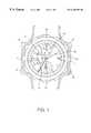
- FIG. 1is a top plan view of a wrist watch of the preferred embodiment corresponding to the present invention
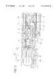
- FIG. 2is a partly sectional view showing the chrono-train wheels of the wrist watch
- FIG. 3is a top plan and perspective diagram of a movement of the wrist watch viewed from the side of a dial;
- FIG. 4is an enlarged top plan view of a working portion of a date plate in FIG. 3;
- FIG. 5is a block diagram showing the system structure of the wrist watch.
- FIG. 1is a top plan view of an embodiment in which the small electronic apparatus of the present invention is applied to a hand display type electronic watch.
- FIG. 2is a partly sectional view showing the chrono-train wheels which drive a chrono-hand in FIG. 1 .
- An hour hand 11 and a minute hand 12 for displaying timeare disposed in the center of the hand display type electronic watch shown in FIGS. 1 and 2 and a second hand 13 is also disposed on the same axis. Further, a twenty four hour hand 14 which works in connection with the hour hand 11 is disposed in the direction of the nine o'clock position of the watch.
- the hour hand 11 , minute hand 12 , and twenty four hour hand 14are driven by an hour-minute motor described below and the second hand 13 is driven by an independent second motor described below.
- a chrono-hand 10is a first display means which displays another function differing from those of the hour, minute, second, and twenty four hour hands and is disposed in the direction of the twelve o'clock position of the watch.
- a date plate 1 for displaying the dateis a second display means which is driven by the same driving means as that of the chrono-hand and exhibits intermittently varying display conditions in connection with the driving force from the driving means.
- the date plate 1displays date by exposing a part from a date glass 21 a opened in a dial 21 .
- a mode hand 15 for indicating a modeis disposed in the direction of the six o'clock position of the watch.
- the mode hand 15indicates a mode switched by a crown 16 which is an external operating member.
- a push button 17which is an external operating member is arranged for operating and amending hand positions in each mode, for example start or stop operations for the chronograph.
- FIG. 3is a top plan and perspective diagram of the hand display type electronic watch shown in FIG. 1, viewed from the side of the dial, showing the locations of each motor and a plurality of train wheels.
- the chrono-hand 10 and the date plate 1are driven by a chrono-motor 22 which is arranged separately from an hour-minute motor 23 and a second motor 24 .
- the chrono-motor 22is a driving means which is constituted of a rotor 6 , a stator 7 , and a coil 8 .
- the chrono-hand 10is attached to the top of a chronograph wheel 9 driven by a rotor 6 via a primary intermediate wheel 5 to display chrono-time and timer time.
- a date plate energy transfer wheel 3 and a date plate drive wheel 2are driven in connection with the chronograph wheel 9 via an auxiliary intermediate wheel 4 to drive the date plate 1 and thereby to display the date.
- the rotor 6 , primary intermediate wheel 5 , chronograph wheel 9 , and auxiliary intermediate wheel 4are supported on the axes by a main plate 18 and a train wheel bridge 19 .
- the date plate energy transfer wheel 3 and the date plate drive wheel 2are supported on the axes by the main plate 18 and a date plate holder 20 for holding a back plate 27 though not shown and the date plate 1 .
- a dial 21the date glass 21 a for displaying the date and other glasses for allowing insertion of each hand are opened.
- a dial support plate 29is installed between the dial 21 and the main plate 18 as a spacer for preventing the date plate 1 from adhering to the dial 21 .
- the date plate 1has a disk form. Patterns for indicating date are formed by printing or the like on the surface of the date plate 1 .
- the date plate 1is driven by the chrono-motor 22 via a chrono-train wheel 31 .
- An internal gear 1 a of the date plate 1is guided by the periphery of the back plate 27 to rotate and indicate date by exposing a part of the patterns from the date glass 21 a which is an opening for the dial 21 .
- the hour-minute motor 23drives the hour hand 11 and the minute hand 12 via an hour-minute train wheel 33 to display the hours and the minutes and drives the twenty four hour hand 14 via a twenty four hour wheel 30 to display the twenty four hour time.
- the second motor 24drives the second hand 13 via a second train wheel 32 , which is driven separately from the hour-minute train wheel 33 , to display the seconds.
- a dial support plate 29is disposed like a ring on the periphery of the date plate 1 .
- a watch circuit 34constituted of circuit parts, such as a crystal oscillator 26 , and an IC 28 transmits driving signals and the like to each motor.
- a winding stem 25conveys to a watch movement the action of the crown 16 operated by an external operation.
- FIG. 4is an enlarged top plan view of FIG. 3 showing an operating portion of the date plate.
- the chrono-motor 22constituted of the rotor 6 , stator 7 , and coil 8 rotates the chronograph wheel 9 via the primary intermediate wheel 5 , thereby rotating the chrono-hand 10 to indicate the chrono-time.
- driving forceis further transferred to the date plate energy transfer wheel 3 from the chronograph wheel 9 via the auxiliary intermediate wheel 4 .
- the date plate energy transfer wheel 3is provided with one pawl 3 a which engages with and turns the date plate drive wheel 2 .
- the arc periphery except for the pawl 3 aforms a stopper 3 b which is interposed between gear teeth to lock the rotation of the date plate drive wheel 2 .
- the date plate energy transfer wheel 3 and the date plate drive wheel 2which have such a structure are combined to form a geneva mechanism thereby intermittently driving the date plate 1 .
- the number of gear teethis designed so that the chronograph wheel 9 turns once every 60 steps of the chronograph motor 22 .
- the chronograph wheel 9rotates according to driving signals from the watch circuit 34 to indicate each display of the functional hands for a chronograph minute display and one-twentieth second display and for a timer minute display.
- the number of gear teethis designed so that the date plate energy transfer wheel 3 turns once every four rotations of the chronograph wheel 9 .
- the pawl 3 amoves forward within a zone A.
- the pawl 3 amoves forward within a zone B, zone C, and zone D during the second, third, and fourth rotations respectively.
- a mode switch 50outputs mode switch data S 1 which indicates the connecting condition of the mode switch.
- the mode signal generating means 51receives the mode switch data S 1 output from the mode switch 50 and detects the present mode of the multifunctional watch to output mode data S 4 .
- the mode internal condition generating means 52detects each condition in the mode from the connecting condition of the push button 17 and the mode data S 4 to output mode internal condition data S 5 .
- the mode data S 4 and the mode internal condition data S 5are used for the following various controls.
- An oscillating means 53outputs a reference signal S 2 for a time check.
- a dividing means 54divides the reference signal S 2 output from the oscillating means 53 to output a dividing signal S 3 .
- a chrono-clocking means 55 , a timer clocking means 56 , and a watch clocking means 57receive the dividing signal S 3 to check respective times.
- a calendar means 58receives an update signal S 16 when the watch clocking means 57 overflows and outputs date data S 8 to update the calendar.
- a chrono-hand driving means 59 as a first function driving meansreceives the mode data S 4 , mode internal condition data S 5 , chrono-minute data S 6 , and timer minute data S 7 to output to the chrono-motor 22 a chrono-hand driving signal S 10 for continuously driving the chrono-hand 10 .
- a date plate driving means 60 as the second function driving meansreceives the date data S 8 to output to the chrono-motor 22 a date plate driving signal S 9 as the second function driving signal for driving the date plate 1 as the second display means.
- the chrono-hand 10indicates a zero (0) position, e.g. a prescribed display condition.
- the chronograph wheel 9makes one rotation based on the count of 60 minutes.
- the pawl 3 a of the date plate energy transfer wheel 3 of the geneva mechanism constituted of the date plate energy transfer wheel 3 and the date plate drive wheel 2moves from the zone A to the zone B.
- the pawl 3 a of the date plate energy transfer wheel 3does not yet reach the zone D where the date plate drive wheel 2 is allowed to rotate.
- the stopper 3 bwhich locks the rotation of the date plate drive wheel 2 still remains engaged.
- the date plate drive wheel 2does not rotate and hence the date plate 1 does not also rotate.
- the chrono-hand driving means 59When the chrono-minute display for 60 minutes is finished, the chrono-hand driving means 59 , which receives the mode internal condition data S 5 requesting “reset” from the chrono-clocking means 55 , outputs a reverse drive pulse to drive the chrono-hand 10 in reverse.
- the chrono-hand 10is returned to the 0 position (prescribed display condition) by the reverse drive and the pawl 3 a of the date plate energy transfer wheel 3 returns to the zone A and remains there.
- the chrono-hand driving means 59generates a driving signal S 10 for driving the chrono-motor 22 only during suspended periods of time, in which the date plate 1 stops operating, between the intermittent actions and allows the chrono-hand 10 to return to the prescribed display condition at the termination of the chrono-minute display.
- the pawl 3 a of the date plate energy transfer wheel 3never exits the zone A even if the chronograph wheel 9 turns to the position set for the timer. After 59 minutes has elapsed, the chronograph wheel 9 returns to the time-up condition (0 position), which is the prescribed condition by reverse drive, and the pawl 3 a of the date plate energy transfer wheel 3 returns to the start position of the zone A and remains there.
- the chrono-hand 10starts to operate and the chronograph wheel 9 makes four revolutions so that the pawl 3 a of the date plate energy transfer wheel 3 makes one rotation from the zone A to the zone A via the zones B, C, and D.
- the pawl 3 a of the date plate energy transfer wheel 3crosses the zone D where it causes the date plate drive wheel 2 to rotate.
- the stopper 3 b which locks the rotation of the date plate drive wheel 2is unlocked from the position between the gear teeth of the date plate drive wheel 2 .
- the pawl 3 a of the date plate energy transfer wheel 3turns the date plate drive wheel 2 in a distance of two gear teeth.
- the stopper 3 bis interposed between the gear teeth of the date plate drive wheel 2 and remains there. Consequently, the date plate 1 is turned and fed the distance of two gear teeth by the date plate drive wheel 2 thereby changing the date.
- the chrono-hand 10returns to the prescribed condition (original 0 position) after the chronograph wheel 9 makes four revolutions.
- the chronograph wheel 9When omitting the 31st day and feeding the date two days in an end of a month with thirty or less days, the chronograph wheel 9 makes eight revolutions so that the pawl 3 a of the date plate energy transfer wheel 3 makes two revolutions.
- the chronograph wheel 9In the case of driving in the direction to set back the date, for example, at the time of amending the date, the chronograph wheel 9 is allowed to turn four times in the reverse direction.
- the pawl 3 a of the date plate energy transfer wheel 3moves from the zone D to the zone A via the zones C and B in this order to reversely drive the date plate drive wheel 2 thereby reversely driving the date plate 1 to set back the date one day.
- the mode switch 50is set to a chronograph mode whereby the mode signal generating means 51 outputs mode data S 4 indicating “chrono-mode”.
- mode internal condition data S 5indicating “chrono-run” is output by pushing the push button 17 .
- the chrono-clocking means 55receives the mode data S 4 and the mode internal condition data S 5 to start chrono-clocking. Then, chrono-minute data S 6 is updated every time a chrono-minute digit is carried.
- the chrono-hand driving means 59which has received the chrono-minute data S 6 calculates the necessary number of motor drive pulses to output a chrono-hand driving signal S 10 . Since the chrono-hand 10 may be carried by one step every minute in the normal direction during the chrono-run, one motor drive pulse is output as the chrono-hand driving signal S 10 every carriage to a minute digit. The chrono-clocking is permitted only during suspended periods of time, in which the date plate stops operating, between intermittent actions.
- the mode internal condition generating means 52outputs mode internal condition data indicating “reset” on pushing the push button 17 .
- the chrono-clocking means 55receives this data to stop clocking and to reset the count to 0.
- the chronominute data S 6is set to 0, whereby the chrono-hand 10 returns to the 0 position. Since chrono-clocking is permitted only during suspended periods of time, in which the date plate stops operating, between intermittent actions, it is necessary to set back by chrono-clocked counts by reverse drive to return to the 0 position without impairing the relation between the date plate 1 and the chrono-hand 10 . For example, in the case of being reset when 33 minutes are clocked, 33 reverse drive pulses are output as the chrono-hand driving signal S 10 . Consequently, the chrono-hand 10 returns to the 0 position by reverse rotation.
- the date plate driving means 60which has received the date data S 8 for update calculates the number of drive pulses of the chrono-motor 22 required to drive the date plate based on the date data S 8 .
- the chrono-hand 10When the date feed is performed during the chrono-run, the chrono-hand 10 must return to the prescribed display condition, e.g. chrono-time display before feeding the date. Because of this, the number of drive pulses is 240 which is calculated by multiplying 4 (revolutions) by 60 (steps).
- 240 drive pulses as the date plate driving signal S 9are output in a group from the date plate driving means 60 .
- the number of drive pulsesis 480.
- the date driving signal S 9is output in the intervals between the times when the chrono-hand driving signal S 10 is output every minute from the chrono-hand driving means 59 .
- the chrono-hand 10makes four revolutions to drive the date plate 1 . Since 240 drive pulses corresponding to four revolutions are output, the position of the chrono-hand 10 for indicating the chrono-time does not change from the position before the date feed even after the date feed has been completed. There is no occasion when chrono-time display malfunctions.
- the pawl 3 a of the date plate energy transfer wheel 3is designed to be positioned in four zones. If the chronograph wheel 9 is designed to operate in the range where the date plate is never carried, the same effect can be obtained. Therefore, two or more divided zones may be designed.
- the display conditionsare varied intermittently in connection with the driving force by means of a geneva mechanism.
- a structuremay be adopted in which the display conditions vary sequentially (continuously) in connection with the driving force by means of a driving means including train wheels of gears in place of the geneva mechanism, whereby a plurality of functional displays can be also achieved.
- the display conditionsare varied intermittently in connection with the driving force by means of a geneva mechanism.
- Display functions using a rotating platesuch as a day dial for displaying days, and a month dial for displaying months, can be structured in the same manner.
- Various display functionssuch as a timer function using hands as well as the chronograph functions can be applied as the functional display means in which the display conditions vary sequentially (continuously) in connection with the driving force from a driving means.
- various functionssuch as a chronograph, timer, date, days, months, and the like are the subjects of the plurality of functions which can be displayed in the present invention.
- a small electronic apparatus provided with the functional display unit according to the present inventionis suitable for electronic devices which are required to display various functions in a pager, portable telephone, and health care instruments such as a passometer, hemodynameter, and the like as well as in an electronic wrist watch.
Landscapes
- Physics & Mathematics (AREA)
- General Physics & Mathematics (AREA)
- Electromagnetism (AREA)
- Electromechanical Clocks (AREA)
- Measurement Of Unknown Time Intervals (AREA)
Abstract
Description
Claims (8)
Applications Claiming Priority (3)
| Application Number | Priority Date | Filing Date | Title |
|---|---|---|---|
| JP8-229610 | 1996-08-30 | ||
| JP22961096AJP3732281B2 (en) | 1996-08-30 | 1996-08-30 | Multifunction clock |
| PCT/JP1997/003035WO1998009200A1 (en) | 1996-08-30 | 1997-08-29 | Small electronic apparatus having function display |
Publications (1)
| Publication Number | Publication Date |
|---|---|
| US6185158B1true US6185158B1 (en) | 2001-02-06 |
Family
ID=16894881
Family Applications (1)
| Application Number | Title | Priority Date | Filing Date |
|---|---|---|---|
| US09/066,371Expired - LifetimeUS6185158B1 (en) | 1996-08-30 | 1997-08-29 | Small electronic apparatus having function display |
Country Status (8)
| Country | Link |
|---|---|
| US (1) | US6185158B1 (en) |
| EP (1) | EP0860756B1 (en) |
| JP (1) | JP3732281B2 (en) |
| CN (1) | CN1123808C (en) |
| BR (1) | BR9706664A (en) |
| DE (1) | DE69738478T2 (en) |
| ES (1) | ES2301182T3 (en) |
| WO (1) | WO1998009200A1 (en) |
Cited By (33)
| Publication number | Priority date | Publication date | Assignee | Title |
|---|---|---|---|---|
| US6310606B1 (en) | 1992-03-05 | 2001-10-30 | Brad A. Armstrong | Multi-plane sheet connected sensors |
| US6344791B1 (en) | 1998-07-24 | 2002-02-05 | Brad A. Armstrong | Variable sensor with tactile feedback |
| US20020019259A1 (en)* | 1997-10-01 | 2002-02-14 | Armstrong Brad A. | Controller with analog pressure sensor (s) |
| US6347997B1 (en)* | 1997-10-01 | 2002-02-19 | Brad A. Armstrong | Analog controls housed with electronic displays |
| US6400303B2 (en) | 1998-09-04 | 2002-06-04 | Brad A. Armstrong | Remote controller with analog pressure sensor (S) |
| US6404584B2 (en) | 1997-10-01 | 2002-06-11 | Brad A. Armstrong | Analog controls housed with electronic displays for voice recorders |
| US6415707B1 (en) | 1997-10-01 | 2002-07-09 | Brad A. Armstrong | Analog controls housed with electronic displays for coffee makers |
| US6456778B2 (en) | 1997-10-01 | 2002-09-24 | Brad A. Armstrong | Analog controls housed with electronic displays for video recorders and cameras |
| US6477114B1 (en)* | 1997-12-26 | 2002-11-05 | Citizen Watch Co., Ltd. | Electronic timepiece with calendar device |
| US6532000B2 (en) | 1997-10-01 | 2003-03-11 | Brad A. Armstrong | Analog controls housed with electronic displays for global positioning systems |
| US6563415B2 (en) | 1996-07-05 | 2003-05-13 | Brad A. Armstrong | Analog sensor(s) with snap-through tactile feedback |
| US20030151983A1 (en)* | 2002-02-14 | 2003-08-14 | Richemont International Sa | Operating unit for the setting devices of a watch and watches incorporating such a unit |
| US20030151984A1 (en)* | 2002-02-14 | 2003-08-14 | Richemont International Sa | Control mechanism for the setting devices of a watch and watches incorporating such a mechanism |
| US20040160414A1 (en)* | 1996-07-05 | 2004-08-19 | Armstrong Brad A. | Image controller |
| US20040208085A1 (en)* | 2003-03-27 | 2004-10-21 | Mamoru Watanabe | Chronograph timepiece having calendar mechanism |
| US6906700B1 (en) | 1992-03-05 | 2005-06-14 | Anascape | 3D controller with vibration |
| US20050231476A1 (en)* | 1996-07-05 | 2005-10-20 | Armstrong Brad A | Image controller |
| US20060240059A1 (en)* | 2005-04-22 | 2006-10-26 | Cardiac Pacemakers, Inc. | Lubricious eluting polymer blend and coating made from the same |
| US20060240060A1 (en)* | 2005-04-22 | 2006-10-26 | Cardiac Pacemakers, Inc. | Lubricious compound and medical device made of the same |
| USD564930S1 (en)* | 2007-01-12 | 2008-03-25 | Seiko Watch Kabushiki Kaisha | Watch dial |
| USD576065S1 (en)* | 2005-10-17 | 2008-09-02 | Societe Anonyme De La Manufacture D'horlogerie Audemars Piguet & Cie. | Watch dial |
| USD632602S1 (en)* | 2010-06-08 | 2011-02-15 | Audemars Piguet Marketing Sa | Watch dial |
| USD649482S1 (en)* | 2010-06-08 | 2011-11-29 | Audemars Piguet Marketing Sa | Watch |
| USD710217S1 (en)* | 2008-03-07 | 2014-08-05 | Salvatore Ferragamo S.P.A. | Watch |
| EP2796943A1 (en)* | 2013-04-24 | 2014-10-29 | ETA SA Manufacture Horlogère Suisse | Watch with special function and improved display |
| EP2884349A1 (en)* | 2013-12-13 | 2015-06-17 | ETA SA Manufacture Horlogère Suisse | Method for controlling an analogue display provided on a watch movement |
| WO2015150086A2 (en) | 2014-04-03 | 2015-10-08 | Eta Sa Manufacture Horlogère Suisse | Electronic clock movement comprising an analog display of several items of information |
| EP2937741A1 (en) | 2014-04-25 | 2015-10-28 | ETA SA Manufacture Horlogère Suisse | Device for driving an analogue display of a timepiece |
| US9261860B2 (en) | 2013-03-21 | 2016-02-16 | Casio Computer Co., Ltd. | Analog electronic timepiece |
| USD749432S1 (en)* | 2014-10-24 | 2016-02-16 | Isaac S. Daniel | Smart watch with tachymeter |
| US20170160702A1 (en)* | 2015-12-07 | 2017-06-08 | Seiko Epson Corporation | Electronic timepiece and display control method of electronic timepiece |
| EP3193217A1 (en) | 2016-01-18 | 2017-07-19 | ETA SA Manufacture Horlogère Suisse | Timepiece movement comprising an analog display |
| USD848866S1 (en)* | 2017-02-22 | 2019-05-21 | Lvmh Swiss Manufactures Sa | Watch case |
Families Citing this family (10)
| Publication number | Priority date | Publication date | Assignee | Title |
|---|---|---|---|---|
| CN101201785B (en)* | 2006-12-11 | 2012-12-05 | 技嘉科技股份有限公司 | Display device |
| JP5087071B2 (en) | 2007-02-22 | 2012-11-28 | シチズンホールディングス株式会社 | Radio correction clock |
| JP2010187524A (en)* | 2009-01-14 | 2010-08-26 | Seiko Epson Corp | Piezoelectric drive device and electronic apparatus |
| JP2010183753A (en)* | 2009-02-06 | 2010-08-19 | Seiko Epson Corp | Piezoelectric driving device and electronic equipment |
| JP4947180B2 (en)* | 2010-04-12 | 2012-06-06 | カシオ計算機株式会社 | Electronic clock |
| JP5606335B2 (en)* | 2011-01-07 | 2014-10-15 | シチズンホールディングス株式会社 | Electronic clock |
| JP5682857B2 (en)* | 2011-03-28 | 2015-03-11 | カシオ計算機株式会社 | Display car drive device |
| JP6194913B2 (en)* | 2015-03-18 | 2017-09-13 | カシオ計算機株式会社 | Analog electronic clock |
| JP7125321B2 (en)* | 2018-10-15 | 2022-08-24 | シチズン時計株式会社 | electronic clock |
| EP4109182A1 (en)* | 2021-06-23 | 2022-12-28 | ETA SA Manufacture Horlogère Suisse | Module for displaying additional time zone |
Citations (13)
| Publication number | Priority date | Publication date | Assignee | Title |
|---|---|---|---|---|
| JPS5467470A (en) | 1977-11-09 | 1979-05-30 | Citizen Watch Co Ltd | Information input device for watch |
| JPS54112677A (en) | 1978-02-22 | 1979-09-03 | Seiko Epson Corp | Calendar watch |
| US4261046A (en)* | 1978-02-23 | 1981-04-07 | Kabushiki Kaisha Suwa Seikosha | Timepiece |
| JPS5956185A (en) | 1982-09-24 | 1984-03-31 | Seiko Epson Corp | Pointer display electronic timepiece |
| JPS6176978A (en) | 1984-09-21 | 1986-04-19 | Citizen Watch Co Ltd | Multifunction analog electronic timepiece |
| US4695168A (en)* | 1985-12-18 | 1987-09-22 | Eta Sa Fabriques D'ebauches | Electronic watch having two motors and comprising means for perpetually indicating the day of the month |
| JPS63124683A (en) | 1986-11-14 | 1988-05-28 | Hitachi Ltd | High pressure generation circuit |
| US5274614A (en)* | 1992-03-31 | 1993-12-28 | Seiko Instruments Inc. | Multi-function analog electronic timepiece |
| JPH0612987A (en) | 1992-06-24 | 1994-01-21 | Oki Electric Ind Co Ltd | Gas discharge type display panel and forming method therreof |
| JPH0628780A (en) | 1992-07-09 | 1994-02-04 | Matsushita Electric Ind Co Ltd | Disk and device for reproducing disk |
| US5384755A (en)* | 1991-12-20 | 1995-01-24 | Eta Sa Fabriques D'ebauches | Timepiece of the mechanical or electromechanical type including a drive wheel controlling at least one display system such as a date display |
| US5473580A (en)* | 1993-03-23 | 1995-12-05 | Eta Sa Fabrique D'ebauches | Chronograph watch with date indicator |
| US5956294A (en)* | 1996-12-26 | 1999-09-21 | Seiko Instruments Inc. | Multi-functional timepiece |
Family Cites Families (7)
| Publication number | Priority date | Publication date | Assignee | Title |
|---|---|---|---|---|
| JPS52111757A (en)* | 1976-03-16 | 1977-09-19 | Citizen Watch Co Ltd | Electroinc watch |
| JPS5424674A (en)* | 1977-07-26 | 1979-02-24 | Citizen Watch Co Ltd | Electronic watch |
| CH616807B (en)* | 1978-07-10 | Berney Sa Jean Claude | ELECTRONIC CLOCK PART WITH A DISC FOR DISPLAYING THE DATE AND AN ANALOGUE DISPLAY OF THE TIME. | |
| JPS63124683U (en)* | 1987-02-06 | 1988-08-15 | ||
| EP0493613B1 (en)* | 1990-07-20 | 1996-04-24 | Citizen Watch Co. Ltd. | Assembly for a hands indicating type timepiece, method for constructing such timepiece and hands indicating type timepiece obtained |
| JP2565072Y2 (en)* | 1992-07-20 | 1998-03-11 | リズム時計工業株式会社 | Calendar display device |
| JP2558516Y2 (en)* | 1992-09-10 | 1997-12-24 | リズム時計工業株式会社 | Multifunctional display clock |
- 1996
- 1996-08-30JPJP22961096Apatent/JP3732281B2/ennot_activeExpired - Lifetime
- 1997
- 1997-08-29DEDE69738478Tpatent/DE69738478T2/ennot_activeExpired - Lifetime
- 1997-08-29USUS09/066,371patent/US6185158B1/ennot_activeExpired - Lifetime
- 1997-08-29EPEP97937851Apatent/EP0860756B1/ennot_activeExpired - Lifetime
- 1997-08-29WOPCT/JP1997/003035patent/WO1998009200A1/enactiveIP Right Grant
- 1997-08-29BRBR9706664Apatent/BR9706664A/ennot_activeIP Right Cessation
- 1997-08-29ESES97937851Tpatent/ES2301182T3/ennot_activeExpired - Lifetime
- 1997-08-29CNCN97191365.XApatent/CN1123808C/ennot_activeExpired - Lifetime
Patent Citations (13)
| Publication number | Priority date | Publication date | Assignee | Title |
|---|---|---|---|---|
| JPS5467470A (en) | 1977-11-09 | 1979-05-30 | Citizen Watch Co Ltd | Information input device for watch |
| JPS54112677A (en) | 1978-02-22 | 1979-09-03 | Seiko Epson Corp | Calendar watch |
| US4261046A (en)* | 1978-02-23 | 1981-04-07 | Kabushiki Kaisha Suwa Seikosha | Timepiece |
| JPS5956185A (en) | 1982-09-24 | 1984-03-31 | Seiko Epson Corp | Pointer display electronic timepiece |
| JPS6176978A (en) | 1984-09-21 | 1986-04-19 | Citizen Watch Co Ltd | Multifunction analog electronic timepiece |
| US4695168A (en)* | 1985-12-18 | 1987-09-22 | Eta Sa Fabriques D'ebauches | Electronic watch having two motors and comprising means for perpetually indicating the day of the month |
| JPS63124683A (en) | 1986-11-14 | 1988-05-28 | Hitachi Ltd | High pressure generation circuit |
| US5384755A (en)* | 1991-12-20 | 1995-01-24 | Eta Sa Fabriques D'ebauches | Timepiece of the mechanical or electromechanical type including a drive wheel controlling at least one display system such as a date display |
| US5274614A (en)* | 1992-03-31 | 1993-12-28 | Seiko Instruments Inc. | Multi-function analog electronic timepiece |
| JPH0612987A (en) | 1992-06-24 | 1994-01-21 | Oki Electric Ind Co Ltd | Gas discharge type display panel and forming method therreof |
| JPH0628780A (en) | 1992-07-09 | 1994-02-04 | Matsushita Electric Ind Co Ltd | Disk and device for reproducing disk |
| US5473580A (en)* | 1993-03-23 | 1995-12-05 | Eta Sa Fabrique D'ebauches | Chronograph watch with date indicator |
| US5956294A (en)* | 1996-12-26 | 1999-09-21 | Seiko Instruments Inc. | Multi-functional timepiece |
Cited By (69)
| Publication number | Priority date | Publication date | Assignee | Title |
|---|---|---|---|---|
| US20060028441A1 (en)* | 1992-03-05 | 2006-02-09 | Armstrong Brad A | Image controller |
| US20020000971A1 (en)* | 1992-03-05 | 2002-01-03 | Armstrong Brad A. | Image controller |
| US9081426B2 (en) | 1992-03-05 | 2015-07-14 | Anascape, Ltd. | Image controller |
| US6906700B1 (en) | 1992-03-05 | 2005-06-14 | Anascape | 3D controller with vibration |
| US7345670B2 (en) | 1992-03-05 | 2008-03-18 | Anascape | Image controller |
| US6310606B1 (en) | 1992-03-05 | 2001-10-30 | Brad A. Armstrong | Multi-plane sheet connected sensors |
| US20060022939A1 (en)* | 1992-03-05 | 2006-02-02 | Armstrong Brad A | Image controller |
| US20060022941A1 (en)* | 1992-03-05 | 2006-02-02 | Armstrong Brad A | Image controller |
| US20060028438A1 (en)* | 1992-03-05 | 2006-02-09 | Armstrong Brad A | Image controller |
| US20060050056A1 (en)* | 1995-02-23 | 2006-03-09 | Armstrong Brad A | Image controller |
| US20060028440A1 (en)* | 1995-02-23 | 2006-02-09 | Armstrong Brad A | Image controller |
| US20060028434A1 (en)* | 1995-02-23 | 2006-02-09 | Armstrong Brad A | Image controller |
| US20060033709A1 (en)* | 1995-02-23 | 2006-02-16 | Armstrong Brad A | Image controller |
| US20060028439A1 (en)* | 1995-02-23 | 2006-02-09 | Armstrong Brad A | Image controller |
| US20060033708A1 (en)* | 1995-02-23 | 2006-02-16 | Armstrong Brad A | Image controller |
| US20060038777A1 (en)* | 1995-02-23 | 2006-02-23 | Armstrong Brad A | Image controller |
| US20060022940A1 (en)* | 1995-02-23 | 2006-02-02 | Armstrong Brad A | Image controller |
| US20030201869A1 (en)* | 1996-07-05 | 2003-10-30 | Armstrong Brad A. | Analog sensor(s) with tactile feedback |
| US20050231476A1 (en)* | 1996-07-05 | 2005-10-20 | Armstrong Brad A | Image controller |
| US6563415B2 (en) | 1996-07-05 | 2003-05-13 | Brad A. Armstrong | Analog sensor(s) with snap-through tactile feedback |
| US8674932B2 (en) | 1996-07-05 | 2014-03-18 | Anascape, Ltd. | Image controller |
| US20040160414A1 (en)* | 1996-07-05 | 2004-08-19 | Armstrong Brad A. | Image controller |
| US6538638B1 (en)* | 1997-10-01 | 2003-03-25 | Brad A. Armstrong | Analog controls housed with electronic displays for pagers |
| US6415707B1 (en) | 1997-10-01 | 2002-07-09 | Brad A. Armstrong | Analog controls housed with electronic displays for coffee makers |
| US6347997B1 (en)* | 1997-10-01 | 2002-02-19 | Brad A. Armstrong | Analog controls housed with electronic displays |
| US6404584B2 (en) | 1997-10-01 | 2002-06-11 | Brad A. Armstrong | Analog controls housed with electronic displays for voice recorders |
| US20020019259A1 (en)* | 1997-10-01 | 2002-02-14 | Armstrong Brad A. | Controller with analog pressure sensor (s) |
| US6456778B2 (en) | 1997-10-01 | 2002-09-24 | Brad A. Armstrong | Analog controls housed with electronic displays for video recorders and cameras |
| US6470078B1 (en) | 1997-10-01 | 2002-10-22 | Brad A. Armstrong | Analog controls housed with electronic displays for telephones |
| US6532000B2 (en) | 1997-10-01 | 2003-03-11 | Brad A. Armstrong | Analog controls housed with electronic displays for global positioning systems |
| US6529185B1 (en) | 1997-10-01 | 2003-03-04 | Brad A. Armstrong | Analog controls housed with electronic displays for electronic books |
| US6518953B1 (en) | 1997-10-01 | 2003-02-11 | Brad A. Armstrong | Analog controls housed with electronic displays for remote controllers having feedback display screens |
| US6496449B1 (en) | 1997-10-01 | 2002-12-17 | Brad A. Armstrong | Analog controls housed with electronic displays for clocks |
| US6477114B1 (en)* | 1997-12-26 | 2002-11-05 | Citizen Watch Co., Ltd. | Electronic timepiece with calendar device |
| US6344791B1 (en) | 1998-07-24 | 2002-02-05 | Brad A. Armstrong | Variable sensor with tactile feedback |
| US6400303B2 (en) | 1998-09-04 | 2002-06-04 | Brad A. Armstrong | Remote controller with analog pressure sensor (S) |
| US6504527B1 (en) | 1999-05-11 | 2003-01-07 | Brad A. Armstrong | Analog controls housed with electronic displays for computer monitors |
| US6559831B1 (en) | 1999-05-11 | 2003-05-06 | Brad A. Armstrong | Analog controls housed with electronic displays for personal digital assistants |
| US6469691B1 (en) | 1999-05-11 | 2002-10-22 | Brad A. Armstrong | Analog controls housed with electronic displays for hand-held web browsers |
| US20030151983A1 (en)* | 2002-02-14 | 2003-08-14 | Richemont International Sa | Operating unit for the setting devices of a watch and watches incorporating such a unit |
| US6918694B2 (en)* | 2002-02-14 | 2005-07-19 | Richemont International Sa | Control mechanism for the setting devices of a watch and watches incorporating such a mechanism |
| US6935773B2 (en)* | 2002-02-14 | 2005-08-30 | Richemont International Sa | Operating unit for the setting devices of a watch and watches incorporating such a unit |
| US20030151984A1 (en)* | 2002-02-14 | 2003-08-14 | Richemont International Sa | Control mechanism for the setting devices of a watch and watches incorporating such a mechanism |
| US20040208085A1 (en)* | 2003-03-27 | 2004-10-21 | Mamoru Watanabe | Chronograph timepiece having calendar mechanism |
| US20060240059A1 (en)* | 2005-04-22 | 2006-10-26 | Cardiac Pacemakers, Inc. | Lubricious eluting polymer blend and coating made from the same |
| US20060240060A1 (en)* | 2005-04-22 | 2006-10-26 | Cardiac Pacemakers, Inc. | Lubricious compound and medical device made of the same |
| USD576065S1 (en)* | 2005-10-17 | 2008-09-02 | Societe Anonyme De La Manufacture D'horlogerie Audemars Piguet & Cie. | Watch dial |
| USD564930S1 (en)* | 2007-01-12 | 2008-03-25 | Seiko Watch Kabushiki Kaisha | Watch dial |
| USD710217S1 (en)* | 2008-03-07 | 2014-08-05 | Salvatore Ferragamo S.P.A. | Watch |
| USD649482S1 (en)* | 2010-06-08 | 2011-11-29 | Audemars Piguet Marketing Sa | Watch |
| USD632602S1 (en)* | 2010-06-08 | 2011-02-15 | Audemars Piguet Marketing Sa | Watch dial |
| US9261860B2 (en) | 2013-03-21 | 2016-02-16 | Casio Computer Co., Ltd. | Analog electronic timepiece |
| EP2796943A1 (en)* | 2013-04-24 | 2014-10-29 | ETA SA Manufacture Horlogère Suisse | Watch with special function and improved display |
| WO2014173780A3 (en)* | 2013-04-24 | 2015-07-02 | Eta Sa Manufacture Horlogère Suisse | Watch having a special function and improved display |
| EP2884349A1 (en)* | 2013-12-13 | 2015-06-17 | ETA SA Manufacture Horlogère Suisse | Method for controlling an analogue display provided on a watch movement |
| KR20150069551A (en)* | 2013-12-13 | 2015-06-23 | 에타 쏘시에떼 아노님 마누팍투레 홀로게레 스위세 | Control method for an analogue display fitted to a timepiece movement |
| US9389589B2 (en) | 2013-12-13 | 2016-07-12 | Eta Sa Manufacture Horlogere Suisse | Control method for an analogue display fitted to a timepiece movement |
| WO2015150086A3 (en)* | 2014-04-03 | 2015-12-10 | Eta Sa Manufacture Horlogère Suisse | Electronic clock movement comprising an analog display of several items of information |
| WO2015150086A2 (en) | 2014-04-03 | 2015-10-08 | Eta Sa Manufacture Horlogère Suisse | Electronic clock movement comprising an analog display of several items of information |
| US9874855B2 (en) | 2014-04-03 | 2018-01-23 | Eta Sa Manufacture Horlogere Suisse | Electronic clock movement comprising an analog display of several items of information |
| EP2937741A1 (en) | 2014-04-25 | 2015-10-28 | ETA SA Manufacture Horlogère Suisse | Device for driving an analogue display of a timepiece |
| USD749432S1 (en)* | 2014-10-24 | 2016-02-16 | Isaac S. Daniel | Smart watch with tachymeter |
| US20170160702A1 (en)* | 2015-12-07 | 2017-06-08 | Seiko Epson Corporation | Electronic timepiece and display control method of electronic timepiece |
| US10101708B2 (en)* | 2015-12-07 | 2018-10-16 | Seiko Epson Corporation | Electronic timepiece and display control method of electronic timepiece |
| EP3193217A1 (en) | 2016-01-18 | 2017-07-19 | ETA SA Manufacture Horlogère Suisse | Timepiece movement comprising an analog display |
| EP3196710A1 (en) | 2016-01-18 | 2017-07-26 | ETA SA Manufacture Horlogère Suisse | Timepiece movement comprising an analogue display |
| US10054907B2 (en) | 2016-01-18 | 2018-08-21 | Eta Sa Manufacture Horlogere Suisse | Timepiece movement including an analogue display |
| USD848866S1 (en)* | 2017-02-22 | 2019-05-21 | Lvmh Swiss Manufactures Sa | Watch case |
| USD848865S1 (en)* | 2017-02-22 | 2019-05-21 | Lvmh Swiss Manufactures Sa | Watch case with strap |
Also Published As
| Publication number | Publication date |
|---|---|
| CN1123808C (en) | 2003-10-08 |
| ES2301182T3 (en) | 2008-06-16 |
| EP0860756B1 (en) | 2008-01-23 |
| EP0860756A4 (en) | 2002-09-25 |
| DE69738478T2 (en) | 2009-01-22 |
| HK1017445A1 (en) | 1999-11-19 |
| CN1205088A (en) | 1999-01-13 |
| WO1998009200A1 (en) | 1998-03-05 |
| JP3732281B2 (en) | 2006-01-05 |
| BR9706664A (en) | 1999-07-20 |
| DE69738478D1 (en) | 2008-03-13 |
| JPH1073673A (en) | 1998-03-17 |
| EP0860756A1 (en) | 1998-08-26 |
Similar Documents
| Publication | Publication Date | Title |
|---|---|---|
| US6185158B1 (en) | Small electronic apparatus having function display | |
| US4748603A (en) | Chronograph watch | |
| CN101833279B (en) | Timepiece including a chronograph and a watch | |
| US5668781A (en) | Analog electronic timepiece having a multifunctional calendar disc | |
| US4433918A (en) | Analog display electronic timepiece with multi-mode display capability | |
| HK1001743A1 (en) | Analogical timepiece with mode changeover warning means | |
| US5305291A (en) | Alarm setting and actuating mechanism for analog timepiece | |
| HK27489A (en) | Electronic timepiece with a chronograph system | |
| GB1572513A (en) | Quartz crystal controlled analogue timepiece | |
| US4261046A (en) | Timepiece | |
| US7120091B1 (en) | Electronic device with calendar function | |
| JPS588511B2 (en) | automatic date display | |
| JP3520406B2 (en) | Calendar display and timing device | |
| JP3063171B2 (en) | Electronic clock | |
| JP2501052Y2 (en) | Pointer display type multi-hand clock | |
| JPS5937793B2 (en) | Clock information input device | |
| JPS6153669B2 (en) | ||
| CN212675374U (en) | Clock movement | |
| JPS63253285A (en) | Analog multihand display timepiece | |
| JPS6133149B2 (en) | ||
| JPH0552967A (en) | Multifunctional electronic timepiece | |
| JPH10148684A (en) | Hand drive mechanism for timepiece | |
| JP2009103658A (en) | Analog electronic clock | |
| JP2993201B2 (en) | Mode display structure of multifunction electronic watch | |
| US20060018201A1 (en) | Method of and device for setting and indicating a plurality of alerts using an indicator hand |
Legal Events
| Date | Code | Title | Description |
|---|---|---|---|
| AS | Assignment | Owner name:CITIZEN WATCH CO., LTD., JAPAN Free format text:ASSIGNMENT OF ASSIGNORS INTEREST;ASSIGNORS:ITO, YUKIO;OKIGAMI, TOMIO;KITAZAWA, ISAO;REEL/FRAME:009482/0490 Effective date:19980401 | |
| FEPP | Fee payment procedure | Free format text:PAYOR NUMBER ASSIGNED (ORIGINAL EVENT CODE: ASPN); ENTITY STATUS OF PATENT OWNER: LARGE ENTITY | |
| STCF | Information on status: patent grant | Free format text:PATENTED CASE | |
| FPAY | Fee payment | Year of fee payment:4 | |
| AS | Assignment | Owner name:CITIZEN HOLDINGS CO., LTD., JAPAN Free format text:CHANGE OF NAME;ASSIGNOR:CITIZEN WATCH CO., LTD.;REEL/FRAME:019817/0701 Effective date:20070402 | |
| FEPP | Fee payment procedure | Free format text:PAYER NUMBER DE-ASSIGNED (ORIGINAL EVENT CODE: RMPN); ENTITY STATUS OF PATENT OWNER: LARGE ENTITY Free format text:PAYOR NUMBER ASSIGNED (ORIGINAL EVENT CODE: ASPN); ENTITY STATUS OF PATENT OWNER: LARGE ENTITY | |
| FPAY | Fee payment | Year of fee payment:8 | |
| FPAY | Fee payment | Year of fee payment:12 |