US6184846B1 - Loop conductor antenna for fuel dispenser - Google Patents
Loop conductor antenna for fuel dispenserDownload PDFInfo
- Publication number
- US6184846B1 US6184846B1US09/497,306US49730600AUS6184846B1US 6184846 B1US6184846 B1US 6184846B1US 49730600 AUS49730600 AUS 49730600AUS 6184846 B1US6184846 B1US 6184846B1
- Authority
- US
- United States
- Prior art keywords
- fuel dispenser
- loop antenna
- antenna
- turns
- panel
- Prior art date
- Legal status (The legal status is an assumption and is not a legal conclusion. Google has not performed a legal analysis and makes no representation as to the accuracy of the status listed.)
- Expired - Lifetime
Links
- 239000000446fuelSubstances0.000titleclaimsabstractdescription94
- 239000004020conductorSubstances0.000titleclaimsabstractdescription23
- 125000006850spacer groupChemical group0.000claimsdescription12
- 238000004891communicationMethods0.000claimsdescription11
- 229910052782aluminiumInorganic materials0.000claimsdescription8
- XAGFODPZIPBFFR-UHFFFAOYSA-NaluminiumChemical compound[Al]XAGFODPZIPBFFR-UHFFFAOYSA-N0.000claimsdescription8
- 230000005540biological transmissionEffects0.000claimsdescription7
- 238000000465mouldingMethods0.000claimsdescription7
- 238000000034methodMethods0.000claimsdescription6
- 239000003989dielectric materialSubstances0.000claimsdescription5
- RYGMFSIKBFXOCR-UHFFFAOYSA-NCopperChemical compound[Cu]RYGMFSIKBFXOCR-UHFFFAOYSA-N0.000claimsdescription4
- 229910052802copperInorganic materials0.000claimsdescription4
- 239000010949copperSubstances0.000claimsdescription4
- 230000006872improvementEffects0.000claimsdescription2
- 239000000463materialSubstances0.000description7
- 239000000370acceptorSubstances0.000description5
- 230000002500effect on skinEffects0.000description5
- 238000005516engineering processMethods0.000description4
- 239000011347resinSubstances0.000description4
- 229920005989resinPolymers0.000description4
- 230000008859changeEffects0.000description3
- 230000000694effectsEffects0.000description3
- 230000006870functionEffects0.000description3
- 230000005855radiationEffects0.000description3
- 238000012795verificationMethods0.000description3
- 230000008901benefitEffects0.000description2
- 230000008878couplingEffects0.000description2
- 238000010168coupling processMethods0.000description2
- 238000005859coupling reactionMethods0.000description2
- 230000003247decreasing effectEffects0.000description2
- PCHJSUWPFVWCPO-UHFFFAOYSA-NgoldChemical compound[Au]PCHJSUWPFVWCPO-UHFFFAOYSA-N0.000description2
- 229910052737goldInorganic materials0.000description2
- 239000010931goldSubstances0.000description2
- 238000001746injection mouldingMethods0.000description2
- 229910052751metalInorganic materials0.000description2
- 239000002184metalSubstances0.000description2
- 239000003209petroleum derivativeSubstances0.000description2
- 238000013459approachMethods0.000description1
- 238000013475authorizationMethods0.000description1
- 239000003990capacitorSubstances0.000description1
- 230000015556catabolic processEffects0.000description1
- 238000005260corrosionMethods0.000description1
- 230000007797corrosionEffects0.000description1
- 238000005034decorationMethods0.000description1
- 230000007423decreaseEffects0.000description1
- 238000006731degradation reactionMethods0.000description1
- 238000011161developmentMethods0.000description1
- 230000009977dual effectEffects0.000description1
- 230000008030eliminationEffects0.000description1
- 238000003379elimination reactionMethods0.000description1
- 239000002828fuel tankSubstances0.000description1
- 230000001939inductive effectEffects0.000description1
- 238000002347injectionMethods0.000description1
- 239000007924injectionSubstances0.000description1
- 238000009413insulationMethods0.000description1
- 239000012212insulatorSubstances0.000description1
- 230000010354integrationEffects0.000description1
- 238000012986modificationMethods0.000description1
- 230000004048modificationEffects0.000description1
- 230000008569processEffects0.000description1
- 230000009467reductionEffects0.000description1
- 238000009420retrofittingMethods0.000description1
- 239000000243solutionSubstances0.000description1
- 238000006467substitution reactionMethods0.000description1
Images


Classifications
- H—ELECTRICITY
- H01—ELECTRIC ELEMENTS
- H01Q—ANTENNAS, i.e. RADIO AERIALS
- H01Q7/00—Loop antennas with a substantially uniform current distribution around the loop and having a directional radiation pattern in a plane perpendicular to the plane of the loop
- G—PHYSICS
- G07—CHECKING-DEVICES
- G07F—COIN-FREED OR LIKE APPARATUS
- G07F13/00—Coin-freed apparatus for controlling dispensing or fluids, semiliquids or granular material from reservoirs
- G07F13/02—Coin-freed apparatus for controlling dispensing or fluids, semiliquids or granular material from reservoirs by volume
- G07F13/025—Coin-freed apparatus for controlling dispensing or fluids, semiliquids or granular material from reservoirs by volume wherein the volume is determined during delivery
- H—ELECTRICITY
- H01—ELECTRIC ELEMENTS
- H01Q—ANTENNAS, i.e. RADIO AERIALS
- H01Q1/00—Details of, or arrangements associated with, antennas
- H01Q1/12—Supports; Mounting means
- H01Q1/22—Supports; Mounting means by structural association with other equipment or articles
Definitions
- This inventionpertains to a loop antenna for placement within a fuel dispenser housing face to facilitate automatic financial transactions.
- Fuel dispensing environmentshave been evolving rapidly with the introduction and development of wireless technology and integrated transaction services. Customers rapidly grew to accept and even demand “pay-at-the-pump” technology wherein a customer did not have to enter the gas station building, but merely had to insert a credit card or debit card into a magnetic card reader on the fuel dispenser. The fuel dispenser was then connected to a remote network, which would secure authorization for the transaction and provide the appropriate cost information to the financial institution so that the account could be properly charged. More advanced units also include cash acceptors which allow a customer to insert cash, in either change or bill form, into the fuel dispenser to pay for the fuel purchased. These cash acceptors work much like conventional vending machines and may provide change. In either situation, a magnetic card reader or a cash acceptor, the customer still had to perform the additional step of interacting with the fuel dispenser to purchase the fuel or other goods and services.
- the next improvement on this payment facilitation technologywas the concept of wireless transactions.
- the customerwould mount a transponder on a card or, later, a vehicle for identification purposes.
- the identification informationwould be coupled with financial account information, either a credit card account, a debit card account or the like.
- Two antennaswere mounted on the top of the fuel dispenser. The first antenna would “ping” the transponder on the vehicle at a first radio frequency, in effect asking, “who are you?”
- the transponder in the card or on the vehiclewould respond on a different radio frequency, stating, in effect, “I am an authorized user and have money to spend to purchase fuel, please authorize me to purchase fuel.” Additional information could also be conveyed.
- the fuel dispenserwould then verify the identification information sent by the transponder, typically over a remote network, and then the fuel transaction would proceed. An example of such an arrangement is seen in the S5000 system sold by the TIRIS division of Texas Instruments.
- This communicationwas implemented by providing a forward link to the transponder by way of an inductive loop transmitting at approximately 134 kHz.
- This forward link antennais typically an oblong coil of wire (about 6 or 7 turns) positioned above the fueling area and more typically over the fuel dispenser.
- the return linktypically operates in the range of 900 MHz and usually requires a second whip antenna.
- the transmitting loop antennashave a directive pattern that is in the form of lobes radiating out the front and back of the loop. Both antennas must have their radiation patterns situated in a manner that allows both patterns to link with the transponder.
- the forward linkis more important than the return link, since the forward link is a magnetic field, which tends to fall off quicker with distance as is well understood.
- the above described arrangementeliminates the need for the customer to perform the step of interacting with the fuel dispenser for the financial part of the transaction, although in the conventional transponder implementation, the transponder had to be brought relatively close to the dispenser to be “pinged.” The customer must then merely lift the nozzle, insert it in the gas tank of the vehicle, select the fuel grade, dispense the fuel and then return the nozzle to its cradle. All of the financial transactions are taken care of automatically.
- the aforesaid concernsare addressed by providing an enhanced radiation loop in a molded package.
- the loop radiation characteristicsare enhanced by the use of a low loss loop constructed of several turns of a flat conductive metal band, such as aluminum or copper, arranged in a concentric coil.
- the loopis preferably embedded in a molded overbody for the fuel dispenser.
- the overbodyacts as an insulation layer, includes a plurality of fasteners or fastener receptacles, and is molded to present a cosmetically pleasing integration of the antenna assembly onto the front face of an existing fuel dispenser.
- the antennais sized to optimize emissions at a desired frequency as is well understood.
- the overbodyis preferably formed from a suitable dielectric material to insulate the antenna, yet still allow transmission of electromagnetic waves therethrough at the desired frequency. Care must be taken in the choice of materials in light of the petroleum product environment in which the overbody will function. However, materials resistant to degradation in the presence of petroleum products are well known in the art.
- the loop antennais formed from one turn of aluminum tubing.
- Aluminumis preferred because of its corrosion-resistant properties in an outdoor environment. Further, one turn has been determined to yield very good results while eliminating some of the molding concerns present with multiple turns.
- FIG. 1shows an isometric view of the loop antenna of the present invention
- FIG. 2illustrates a front elevational view of the antenna of FIG. 1 with a dielectric tape positioned within the coils;
- FIG. 3demonstrates a front elevational view of the antenna of FIG. 1 with spacers positioned within the coils;
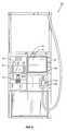
- FIG. 4pictures a front elevational view of a first embodiment of a fuel dispenser equipped with the loop antenna of FIG. 1;
- FIG. 5depicts a second embodiment of a fuel dispenser equipped with the loop antenna of FIG. 1;
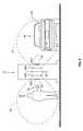
- FIG. 6features a third embodiment of a fuel dispenser equipped with the loop antenna of FIG. 1;
- FIG. 7shows an enlarged perspective view of the embodiment of FIG. 6
- FIG. 8illustrates a schematic view of a fuel dispenser of the present invention in use with transponders.
- FIG. 9demonstrates a front elevational view of a prior art fuel dispenser.
- FIG. 9shows a prior art fuel dispenser 120 with face 130 .
- the fuel dispenser 120provides a fuel delivery path from an underground storage tank (not shown) to a vehicle (not shown).
- the delivery pathincludes a fuel delivery line 132 having a fuel metering device 134 .
- the fuel delivery line 132communicates with a fuel delivery hose 136 outside of the dispenser 120 and a delivery nozzle 138 .
- the nozzle 138provides manual control of fuel delivery to the vehicle.
- the dispenser 120also includes a dispenser control system 140 having one or more controllers and associated memory 142 .
- the dispenser control system 140may receive volume data from the metering device 134 through cabling 144 as well as provide control of fuel delivery.
- the dispenser control system 140may provide audible signals to a speaker 126 in order to provide various beeps, tones and audible messages to a customer.
- the dispenser 120is preferably equipped with a payment acceptor, such as a card reader 148 or a cash acceptor 150 , along with a receipt printer 152 .
- a payment acceptorsuch as a card reader 148 or a cash acceptor 150
- the dispenser 45 control system 140may read data from the magnetic strip of a card inserted in the card reader 148 or receive cash from a customer and communicate such information to an attendant terminal (not shown), such as the G-SITE® controller sold by Marconi Commerce Systems, Inc., 7300 West Friendly Avenue, Greensboro, N.C.
- the attendant terminaltypically communicates with a remote network (not shown), such as a card verification authority, to ascertain whether a transaction proposed to be charged to or debited from an account associated with the card inserted in the card reader 148 is authorized.
- the dispenser 120may include one or more types of displays, preferably one or more alpha-numeric displays 122 together with a high resolution graphics display 127 .
- the graphics display 127will generally have an associated keypad 128 adjacent to the display or integrated with the display to provide a touch interface.
- the dispenser 120may include an additional, auxiliary key pad 156 associated with the card reader 148 for entering secret codes or personal identification numbers (PINs).
- PINspersonal identification numbers
- the displays 122 , 127 and keypads 128 , 156may be integrated into a single device and/or touch interface.
- the dispenser control system 140is preferably comparable to the microprocessor-based control systems used in CRIND (card reader in dispenser) and TRIND (tag or transponder reader in dispenser) type units sold by Marconi Commerce Systems, Inc. under the trademark THE ADVANTAGE.
- the loop antennasare mounted underneath the upper piping housing 159 or at the very top 160 of the fuel dispenser 120 . As noted, this may interfere with the placement of desired corporate logos or other advertising, as well as be unsightly.
- Loop antennasin general are well understood and operate at a frequency dictated by the inductance (L) of the loop and the capacitance (C) of the associated capacitor (not shown) according to the following equation:
- the magnetic field strengthis proportional to the product of the number of turns of the loop multiplied by the magnitude of the current in the coil. For maximum magnetic field strength, the current and the number of turns must both be maximized. The difficulty is that when operating from a limited power source, the factors involved make it difficult to maximize both, since they tend to be counterproductive. As the number of turns are increased, the inductance of the coil increases, the impedance of the coil increases, and the loop current drops due to the higher impedance of the coil. As the number of turns are decreased, the situation may result in more current due to lower inductance and lower impedance, but the turns have decreased, resulting in a lower magnetic field strength.
- Skin effectis a phenomenon which happens at radio frequencies whereby the radio frequency current will only flow proximate the outside of a conductor. As the frequency increases, the skin depth decreases to a point where the current is flowing only on the surface of a conductor. For example, at 130 kHz, which is approximately the frequency for the downlink antennas of the present system, the skin depth is approximately 0.007 inches.
- the present inventionsolves these concerns by providing a loop antenna 20 as seen in FIG. 1 .
- the loop antennais preferably a flat conductor 22 coiled into a number of concentric turns 24 , much like a tape measure.
- a pair of electrical leads 24 and 26provide electrical connection from the loop antenna 20 to a communications electronics circuit 17 (FIG. 4) for control of the transmission and receipt of electromagnetic signals by the loop antenna 20 .
- the appropriate number of turns 24 in the loop antenna 20is in part dictated by the space is limitations discussed above, although between one and fifteen turns would cover most embodiments, especially at the desired operating frequency of 134 kHz. However, in the preferred embodiment, between one (1) and ten (10) turns are used, although more turns may be used. For example, with appropriate circuitry modifications, one turn is possible and effective.
- Suitable conductorsinclude copper, aluminum, gold and other well known electrically conductive materials. As always, the choice of conductor is dictated by engineering and cost effectiveness. Copper is a good conductor, but corrodes if exposed to weather and time. Aluminum does not corrode in a manner which affects the electrical properties, but is not as good a conductor. Gold does not corrode, and is a good conductor, but is extremely expensive.
- the loop antenna 20is formed from one turn of aluminum tubing and may be sized to provide the appropriate operative frequency.
- the conductor 22may be shaped into a wide, flat band prior to coiling. While the overall dimensions of the antenna 20 will be dictated by the geometry of its mounting discussed below, the generally acceptable width 28 of the conductor 22 is between about ⁇ fraction (1/16) ⁇ and 1 inch (0.16-2.54 cm) and preferably between about 1 ⁇ 4 and 1 ⁇ 2 inch (0.64-1.27 cm).
- the flat bandis additionally preferred because it helps reduce or eliminate losses incurred by the skin effect. The thickness of the band is determined in part by the desired operating frequencies and the resulting skin effect. Additionally, this wide, flat band has a low DC resistance due to the substantial cross-sectional area. As the tubing in the preferred embodiment is relatively thin, losses incurred by the skin effect are eliminated or reduced. It should be appreciated that the tubing may be cylindrical or rectillnear as needed or desired.
- spaces 30In order to prevent electrical shorts between concentric turns 24 , spaces 30 must exist therebetween. As seen in FIG. 2, these spaces 30 may be formed by a dielectric tape 32 . There will be a capacitive coupling between concentric turns 24 which will affect the operative frequency due to turns 24 close proximity if a dielectric tape 32 is used. To reduce this coupling, spacers 34 as shown in FIG. 3 may be used in addition to, or in place of, the dielectric tape 32 . While the dielectric tape 32 may be as thin as approximately 0.001 inch, the spacers 34 are preferably around ⁇ fraction (1/32) ⁇ to ⁇ fraction (1/16) ⁇ of an inch thick.
- One of the advantages of the aluminum tubing in the preferred embodimentis the elimination of the need for spacers and a reduction in the molding concerns associated with molding the antenna 20 into a bezel as described below.
- the present loop antennas 20are mounted in the front face 130 of the fuel dispenser 10 as shown in FIGS. 4-6.
- the fuel dispensers 10 of FIGS. 4-6are identical except for the placement of the loop antenna 20 , and will be described only once.
- Most fuel dispensers 10include a bezel 12 which acts as a lip around a display 14 and a keypad 16 .
- An additional bezel 18may be positioned around a panel 19 .
- the panel 19may be adapted to show a logo, an advertisement or contain an access panel 36 for entry into the interior of the fuel dispenser 10 .
- Lock 38prevents unauthorized entry, and while shown with hinges, access panel 36 may be removable.
- the bezels 12 and 18are flush with the face 130 of the fuel dispenser, however, in certain embodiments, the bezels 12 and 18 may extend outwardly from the face 130 , in effect forming a raised lip (FIG. 7 ).
- the loop antenna 20 of the present inventionmay be placed in one of several locations within the face 130 of the fuel dispenser 10 .
- the loop antenna 20is integrally molded with panel 19 (FIG. 4 ).
- the loop antenna 20is positioned within the bezel 12 surrounding user interface elements such as the display 14 and the keypad 16 (FIG. 5 ).
- the loop antenna 20is positioned within the bezel 18 surrounding the panel 19 (FIGS. 6 and 7 ).
- a fourth embodimentpositions the loop antenna 20 around the nozzle mount 139 . In all the embodiments, the loop antenna 20 is positioned within the face 130 of the fuel dispenser 10 .
- FIG. 7For a better understanding of how the antenna 20 may be positioned in a bezel, reference is made to FIG. 7, wherein the panel 19 , the bezel 18 and the loop antenna 20 have been removed from the fuel dispenser and enlarged for clarity.
- the bezel 18extends outwardly from the front surface 21 of the panel 19 and the loop antenna 20 is shown positioned within the bezel 18 .
- This arrangementis particularly well suited for retrofitting on deployed fuel dispensers. It should be noted that the relative position of the antenna 20 within the bezel 18 does not change if the top surface 23 of the bezel 18 is flush with the front surface 21 of the panel 19 .
- the loop antenna 20is position within panels which are not surrounded by bezels or to put the antenna 20 within panels including other elements, for example, the keypad 16 and display 14 .
- generally rectilinear loop antennasare shown, it is within the scope of the present invention to use circular loop antennas with similar characteristics.
- the antenna loop 20is shown with just one loop, a plurality of loops as described can be employed in these embodiments.
- an overbodyis easily adapted to be retrofitted onto existing deployed fuel dispensers and includes, doors, panels, surrounding bezels or add on pieces which are easily adapted for attachment to the face of a fuel dispenser such as fuel dispenser 10 .
- the present inventioncould be positioned in a deployed fuel dispenser without high cost.
- an existing panel 19would be removed from the deployed fuel dispenser and swapped with a panel 19 incorporating the antenna 20 . The appropriate electrical connections are made and the dispenser is ready to dispense fuel once more.
- FIG. 19Another example of such a retrofit would be to create a bezel extending around the edge of a panel, such as panel 19 , with the antenna 20 positioned within the bezel. Again the appropriate electrical connections are made and the dispenser 10 is ready. This requires the removal of no parts. Appropriate fasteners (not shown) would be needed to secure the new bezel to the old dispenser 10 .
- the antenna 20electrically communicates with communications electronics 17 (FIG. 4 ), which are preferably positioned within the dispenser 10 .
- the communications electronics 17are conventional and similar to those used in the Texas Instruments machines.
- the communications electronics 17dictate the signal radiated by the antenna 20 and translate the signal received from the transponder by the antenna 20 .
- the communications electronics 17may serve the dual purpose of communicating with an outside network (not shown) for credit card verification, transponder account verification or the like as needed by the fuel dispensing environment.
- the panel 19is preferably molded from an appropriate material with the antenna 20 therein. This may be accomplished by injection molding or insert molding as desired or needed. Of particular interest for injection molding is the use of spacers 34 .
- the use of the spacers 34allows the material used to mold the panel 19 to flow between the turns 24 of the conductor. As a result, in such instances the material of the panel 19 should be a good dielectric material.
- the material used to make the panel 19should also be a good insulator to prevent accidental electrical discharge therethrough to a customer or the like. Since the resin used in the molding process has particular mold flow characteristics, the spacers 34 must be thick enough to allow the resin to flow into the spaces 30 .
- a space of between about ⁇ fraction (1/32) ⁇ and ⁇ fraction (1/16) ⁇ of an inchwill be enough for most resins used in a fuel dispensing environment.
- the space 30 created by the spacers 34could be changed to reflect the differing mold flow characteristics.
- the material used to form the panelwould just coat the antenna 20 .
- the antenna 20can be injection or insert molded as desired, or merely positioned within a hollow cavity within the bezel 12 or 18 .
- the present inventionis seen in use in FIG. 8 .
- the antenna 20 Acreates magnetic field lobe 40 , which is large enough to communicate with a transponder 44 carried in a vehicle 46 .
- the loop antenna 20 Bcreates magnetic field lobe 42 which communicates with a transponder 44 carried by an individual person 48 .
- Additional smaller loop antennas 20 C and 20 Dmay be used to create smaller magnetic fields 55 , which may be more appropriate for reading handheld transponders, such as transponder 44 carried by an individual 48 .
- all loop antennas 20 A through 20 Dpreferably communicate at approximately 130 kHz, and more preferably at 134.2 kHz. This arrangement allows discernment by the communication electronics 17 as to whether the transponder 44 is on the front or rear side of the dispenser 10 . Additionally, the use of the smaller loop antennas 20 C, 20 D allows the customer to deliberately bring the transponder 44 into the smaller lobe 55 to prevent accidental or unintentional reading of the transponder 44 by the antennas 20 .
- the communication electronics 17discern which transponder 44 has been presented to which antenna 20 by multiplexing the sending and receiving of data from the various antennas. This arrangement is an optional arrangement and the fuel dispenser may be limited to two or four antennas as is needed or desired. In theory, one antenna 20 could be used for both sides of the fuel dispenser 10 ; however, such is not desired as confusion may result in which side of the fuel dispenser has been authorized to dispense fuel.
- the transponders 44reply to communications from the loop antenna 20 at approximately 900 MHz, or 2.45 GHz. This reply communication is received at a conventional whip antenna (not shown). While it is possible that the transponder 44 respond at approximately 130 kHz, and thus eliminate the need for a whip antenna in the dispenser, this substitution would require a different antenna than is currently used in the transponders 44 . This new antenna would be substantially larger than those presently in use in transponders 44 would, making the transponders 44 more cumbersome and bulky.
- the lobes 40 , 42should be operatively strong enough to encompass an area expected to contain a car mounted transponder 44 during fueling.
- the electromagnetic waves usedare in the radio frequency, although other frequencies may be acceptable. It should be appreciated that the transponder 44 may be positioned almost anywhere on the vehicle 46 , but is preferably on the fuel tank side of the vehicle 46 to prevent interference from the body 50 of the vehicle 46 .
Landscapes
- Physics & Mathematics (AREA)
- General Physics & Mathematics (AREA)
- Support Of Aerials (AREA)
- Details Of Aerials (AREA)
Abstract
Description
Claims (39)
Priority Applications (1)
| Application Number | Priority Date | Filing Date | Title |
|---|---|---|---|
| US09/497,306US6184846B1 (en) | 2000-02-03 | 2000-02-03 | Loop conductor antenna for fuel dispenser |
Applications Claiming Priority (1)
| Application Number | Priority Date | Filing Date | Title |
|---|---|---|---|
| US09/497,306US6184846B1 (en) | 2000-02-03 | 2000-02-03 | Loop conductor antenna for fuel dispenser |
Publications (1)
| Publication Number | Publication Date |
|---|---|
| US6184846B1true US6184846B1 (en) | 2001-02-06 |
Family
ID=23976315
Family Applications (1)
| Application Number | Title | Priority Date | Filing Date |
|---|---|---|---|
| US09/497,306Expired - LifetimeUS6184846B1 (en) | 2000-02-03 | 2000-02-03 | Loop conductor antenna for fuel dispenser |
Country Status (1)
| Country | Link |
|---|---|
| US (1) | US6184846B1 (en) |
Cited By (23)
| Publication number | Priority date | Publication date | Assignee | Title |
|---|---|---|---|---|
| US6364206B1 (en)* | 2000-01-19 | 2002-04-02 | Marconi Commerce Systems Inc. | Lottery ticket sales in fueling forecourt |
| US6386459B1 (en)* | 1998-03-30 | 2002-05-14 | Gemplus | Contactless integrated-circuit card comprising inhibiting means |
| US20030224783A1 (en)* | 2002-05-08 | 2003-12-04 | Ruddell Gregory Marshall | System for providing displays in an outdoors retail area of a retail store |
| US6810304B1 (en)* | 1997-09-26 | 2004-10-26 | Gilbarco Inc. | Multistage ordering system for a fueling and retail environment |
| US20070216532A1 (en)* | 2004-05-24 | 2007-09-20 | Lansdowne David C | Identification of Biological Samples |
| US7565307B1 (en)* | 2000-12-21 | 2009-07-21 | Tc License Ltd. | Automatic payment method using RF ID tags |
| US7571139B1 (en) | 1999-02-19 | 2009-08-04 | Giordano Joseph A | System and method for processing financial transactions |
| US20100108755A1 (en)* | 2008-10-30 | 2010-05-06 | Zack Fuerstenberg | Beverage Holder Having a Chip Unit for Performing Payment Transactions |
| US20100258587A1 (en)* | 2009-04-13 | 2010-10-14 | Wheeler Loyde A | Windshield Washer Fluid Dispenser |
| WO2011153249A1 (en)* | 2010-06-01 | 2011-12-08 | Gilbarco, Inc. | Remote transaction system utilizing compact antenna assembly |
| US20120206239A1 (en)* | 2010-03-24 | 2012-08-16 | Murata Manufacturing Co., Ltd. | Rfid system |
| US8433441B2 (en)* | 2011-07-12 | 2013-04-30 | Gilbarco Inc. | Fuel dispenser having FM transmission capability for fueling information |
| US8538801B2 (en) | 1999-02-19 | 2013-09-17 | Exxonmobile Research & Engineering Company | System and method for processing financial transactions |
| US20140074282A1 (en)* | 2012-01-26 | 2014-03-13 | Progressive International Electronics, Inc. | Multiplexing system for a fuel transaction environment |
| US20150317933A1 (en)* | 2010-04-30 | 2015-11-05 | Gilbarco Inc. | Fuel dispenser |
| US9340405B2 (en) | 2012-01-26 | 2016-05-17 | Progressive International Electronics Inc. | Fuel transaction tracking system |
| WO2016103220A3 (en)* | 2014-12-23 | 2016-08-18 | Gilbarco Inc. | Fuel dispenser wireless communication arrangement |
| US9708170B2 (en) | 2009-02-11 | 2017-07-18 | Pepsico, Inc. | Beverage dispense valve controlled by wireless technology |
| US9911293B2 (en)* | 2015-01-12 | 2018-03-06 | Jonathan Lee | Security device for integration into a security system |
| US10318963B1 (en)* | 2014-05-12 | 2019-06-11 | United Services Automobile Association (Usaa) | System and methods for performing vehicle renewal services at an integrated dispensing terminal |
| US20230249958A1 (en)* | 2022-02-10 | 2023-08-10 | Garton Enterprise, LLC | Refueling station protective door cover |
| US11836737B1 (en) | 2015-04-15 | 2023-12-05 | United Services Automobile Association (Usaa) | Automated vehicle ownership support |
| US20230411824A1 (en)* | 2020-11-12 | 2023-12-21 | Banks And Acquirers International Holding | Radio communication antenna consisting of a previously bent rigid metallic wire, support structure and corresponding payment terminal |
Citations (28)
| Publication number | Priority date | Publication date | Assignee | Title |
|---|---|---|---|---|
| US2401472A (en) | 1945-03-24 | 1946-06-04 | Albert W Franklin | Structural unit |
| US2551664A (en) | 1949-11-29 | 1951-05-08 | Galper Samuel | Television antenna |
| US3560983A (en)* | 1967-09-12 | 1971-02-02 | Volkers Research Corp | Omnidirectional loop antenna |
| US3919704A (en) | 1972-12-04 | 1975-11-11 | Check Mate Systems Inc | System and method for detecting unauthorized removal of goods from protected premises, and magnet detecting apparatus suitable for use therein |
| US4804695A (en) | 1987-09-03 | 1989-02-14 | Western Fibers, Inc. | Method and composition for producing and installing cellulosic installation |
| US4914449A (en) | 1987-11-30 | 1990-04-03 | Sony Corporation | Microwave antenna structure with intergral radome and rear cover |
| US4914448A (en) | 1987-11-30 | 1990-04-03 | Sony Corporation | Microwave antenna structure |
| US4940992A (en) | 1988-04-11 | 1990-07-10 | Nguyen Tuan K | Balanced low profile hybrid antenna |
| US5361061A (en) | 1992-10-19 | 1994-11-01 | Motorola, Inc. | Computer card data receiver having a foldable antenna |
| US5373303A (en) | 1991-12-30 | 1994-12-13 | Texas Instruments Incorporated | Built-in chip transponder with antenna coil |
| US5455596A (en) | 1992-12-11 | 1995-10-03 | Fujitsu Limited | Antenna module for incorporation in wireless terminal equipment such as portable telephone |
| US5469178A (en) | 1992-09-30 | 1995-11-21 | Motorola, Inc. | Low profile antenna system for a cardlike communication receiver |
| US5491483A (en) | 1994-01-05 | 1996-02-13 | Texas Instruments Incorporated | Single loop transponder system and method |
| US5555459A (en) | 1992-03-27 | 1996-09-10 | Norand Corporation | Antenna means for hand-held data terminals |
| US5557279A (en) | 1993-09-28 | 1996-09-17 | Texas Instruments Incorporated | Unitarily-tuned transponder/shield assembly |
| US5574470A (en) | 1994-09-30 | 1996-11-12 | Palomar Technologies Corporation | Radio frequency identification transponder apparatus and method |
| US5594448A (en) | 1993-10-22 | 1997-01-14 | Texas Instruments Incorporated | Highly accurate RF-ID positioning system |
| US5598032A (en)* | 1994-02-14 | 1997-01-28 | Gemplus Card International | Hybrid chip card capable of both contact and contact-free operation and having antenna contacts situated in a cavity for an electronic module |
| US5621411A (en) | 1993-10-04 | 1997-04-15 | Texas Instruments Incorporated | Positioning with RF-ID transponders |
| US5629712A (en) | 1995-10-06 | 1997-05-13 | Ford Motor Company | Vehicular slot antenna concealed in exterior trim accessory |
| US5675342A (en) | 1993-02-23 | 1997-10-07 | Texas Instruments Incorporated | Automatic vehicle identification system capable of vehicle lane discrimination |
| US5691731A (en) | 1993-06-15 | 1997-11-25 | Texas Instruments Incorporated | Closed slot antenna having outer and inner magnetic loops |
| US5694139A (en) | 1994-06-28 | 1997-12-02 | Sony Corporation | Short-distance communication antenna and methods of manufacturing and using the short-distance communication antenna |
| US5714937A (en) | 1995-02-24 | 1998-02-03 | Ntp Incorporated | Omidirectional and directional antenna assembly |
| US5732579A (en) | 1994-11-30 | 1998-03-31 | Texas Instruments Incorporated | Key having an air coil antenna and a method of construction |
| US5760747A (en) | 1996-03-04 | 1998-06-02 | Motorola, Inc. | Energy diversity antenna |
| US5906228A (en) | 1997-09-24 | 1999-05-25 | Dresser Industries, Inc. | Gasoline dispensing system and method with radio frequency customer identification antenna |
| US5969691A (en)* | 1998-02-10 | 1999-10-19 | Gilbarco Inc. | Fuel dispenser transponder antenna arrangement |
- 2000
- 2000-02-03USUS09/497,306patent/US6184846B1/ennot_activeExpired - Lifetime
Patent Citations (30)
| Publication number | Priority date | Publication date | Assignee | Title |
|---|---|---|---|---|
| US2401472A (en) | 1945-03-24 | 1946-06-04 | Albert W Franklin | Structural unit |
| US2551664A (en) | 1949-11-29 | 1951-05-08 | Galper Samuel | Television antenna |
| US3560983A (en)* | 1967-09-12 | 1971-02-02 | Volkers Research Corp | Omnidirectional loop antenna |
| US3919704A (en) | 1972-12-04 | 1975-11-11 | Check Mate Systems Inc | System and method for detecting unauthorized removal of goods from protected premises, and magnet detecting apparatus suitable for use therein |
| US4804695A (en) | 1987-09-03 | 1989-02-14 | Western Fibers, Inc. | Method and composition for producing and installing cellulosic installation |
| US4914448A (en) | 1987-11-30 | 1990-04-03 | Sony Corporation | Microwave antenna structure |
| US4914449A (en) | 1987-11-30 | 1990-04-03 | Sony Corporation | Microwave antenna structure with intergral radome and rear cover |
| US4940992A (en) | 1988-04-11 | 1990-07-10 | Nguyen Tuan K | Balanced low profile hybrid antenna |
| US5373303A (en) | 1991-12-30 | 1994-12-13 | Texas Instruments Incorporated | Built-in chip transponder with antenna coil |
| US5555459A (en) | 1992-03-27 | 1996-09-10 | Norand Corporation | Antenna means for hand-held data terminals |
| US5469178A (en) | 1992-09-30 | 1995-11-21 | Motorola, Inc. | Low profile antenna system for a cardlike communication receiver |
| US5361061A (en) | 1992-10-19 | 1994-11-01 | Motorola, Inc. | Computer card data receiver having a foldable antenna |
| US5455596A (en) | 1992-12-11 | 1995-10-03 | Fujitsu Limited | Antenna module for incorporation in wireless terminal equipment such as portable telephone |
| US5675342A (en) | 1993-02-23 | 1997-10-07 | Texas Instruments Incorporated | Automatic vehicle identification system capable of vehicle lane discrimination |
| US5701127A (en) | 1993-02-23 | 1997-12-23 | Texas Instruments Incorporated | Automatic vehicle identification system capable of vehicle lane discrimination |
| US5691731A (en) | 1993-06-15 | 1997-11-25 | Texas Instruments Incorporated | Closed slot antenna having outer and inner magnetic loops |
| US5557279A (en) | 1993-09-28 | 1996-09-17 | Texas Instruments Incorporated | Unitarily-tuned transponder/shield assembly |
| US5621411A (en) | 1993-10-04 | 1997-04-15 | Texas Instruments Incorporated | Positioning with RF-ID transponders |
| US5619207A (en) | 1993-10-22 | 1997-04-08 | Texas Instruments Incorporated | Highly accurate RE-ID positioning system |
| US5594448A (en) | 1993-10-22 | 1997-01-14 | Texas Instruments Incorporated | Highly accurate RF-ID positioning system |
| US5491483A (en) | 1994-01-05 | 1996-02-13 | Texas Instruments Incorporated | Single loop transponder system and method |
| US5598032A (en)* | 1994-02-14 | 1997-01-28 | Gemplus Card International | Hybrid chip card capable of both contact and contact-free operation and having antenna contacts situated in a cavity for an electronic module |
| US5694139A (en) | 1994-06-28 | 1997-12-02 | Sony Corporation | Short-distance communication antenna and methods of manufacturing and using the short-distance communication antenna |
| US5574470A (en) | 1994-09-30 | 1996-11-12 | Palomar Technologies Corporation | Radio frequency identification transponder apparatus and method |
| US5732579A (en) | 1994-11-30 | 1998-03-31 | Texas Instruments Incorporated | Key having an air coil antenna and a method of construction |
| US5714937A (en) | 1995-02-24 | 1998-02-03 | Ntp Incorporated | Omidirectional and directional antenna assembly |
| US5629712A (en) | 1995-10-06 | 1997-05-13 | Ford Motor Company | Vehicular slot antenna concealed in exterior trim accessory |
| US5760747A (en) | 1996-03-04 | 1998-06-02 | Motorola, Inc. | Energy diversity antenna |
| US5906228A (en) | 1997-09-24 | 1999-05-25 | Dresser Industries, Inc. | Gasoline dispensing system and method with radio frequency customer identification antenna |
| US5969691A (en)* | 1998-02-10 | 1999-10-19 | Gilbarco Inc. | Fuel dispenser transponder antenna arrangement |
Cited By (35)
| Publication number | Priority date | Publication date | Assignee | Title |
|---|---|---|---|---|
| US6810304B1 (en)* | 1997-09-26 | 2004-10-26 | Gilbarco Inc. | Multistage ordering system for a fueling and retail environment |
| US6386459B1 (en)* | 1998-03-30 | 2002-05-14 | Gemplus | Contactless integrated-circuit card comprising inhibiting means |
| US8538801B2 (en) | 1999-02-19 | 2013-09-17 | Exxonmobile Research & Engineering Company | System and method for processing financial transactions |
| US7571139B1 (en) | 1999-02-19 | 2009-08-04 | Giordano Joseph A | System and method for processing financial transactions |
| US6364206B1 (en)* | 2000-01-19 | 2002-04-02 | Marconi Commerce Systems Inc. | Lottery ticket sales in fueling forecourt |
| US7565307B1 (en)* | 2000-12-21 | 2009-07-21 | Tc License Ltd. | Automatic payment method using RF ID tags |
| US20030224783A1 (en)* | 2002-05-08 | 2003-12-04 | Ruddell Gregory Marshall | System for providing displays in an outdoors retail area of a retail store |
| US20070216532A1 (en)* | 2004-05-24 | 2007-09-20 | Lansdowne David C | Identification of Biological Samples |
| US9547782B2 (en) | 2004-05-24 | 2017-01-17 | Research Instruments Limited | Identification of biological samples |
| US10207270B2 (en)* | 2004-05-24 | 2019-02-19 | Research Instruments Limited | Identification of biological samples |
| US9211540B2 (en)* | 2004-05-24 | 2015-12-15 | Research Instruments Limited | Identification of biological samples |
| US20170087554A1 (en)* | 2004-05-24 | 2017-03-30 | Research Instruments Limited | Identification of biological samples |
| US20100108755A1 (en)* | 2008-10-30 | 2010-05-06 | Zack Fuerstenberg | Beverage Holder Having a Chip Unit for Performing Payment Transactions |
| US9471915B2 (en)* | 2008-10-30 | 2016-10-18 | Visa U.S.A., Inc. | Beverage holder having a chip unit for performing payment transactions |
| US10210492B2 (en)* | 2008-10-30 | 2019-02-19 | Visa U.S.A. Inc. | Beverage holder having a chip unit for performing payment transactions |
| US20170004464A1 (en)* | 2008-10-30 | 2017-01-05 | Zack Fuerstenberg | Beverage holder having a chip unit for performing payment transactions |
| US9708170B2 (en) | 2009-02-11 | 2017-07-18 | Pepsico, Inc. | Beverage dispense valve controlled by wireless technology |
| US12291443B2 (en) | 2009-02-11 | 2025-05-06 | Pepsico, Inc. | Beverage dispense valve controlled by wireless technology |
| US10315907B2 (en) | 2009-02-11 | 2019-06-11 | Pepsico, Inc. | Beverage dispense valve controlled by wireless technology |
| US20100258587A1 (en)* | 2009-04-13 | 2010-10-14 | Wheeler Loyde A | Windshield Washer Fluid Dispenser |
| US9727765B2 (en)* | 2010-03-24 | 2017-08-08 | Murata Manufacturing Co., Ltd. | RFID system including a reader/writer and RFID tag |
| US20120206239A1 (en)* | 2010-03-24 | 2012-08-16 | Murata Manufacturing Co., Ltd. | Rfid system |
| US20150317933A1 (en)* | 2010-04-30 | 2015-11-05 | Gilbarco Inc. | Fuel dispenser |
| US10019953B2 (en)* | 2010-04-30 | 2018-07-10 | Gilbarco Inc. | Fuel dispenser |
| WO2011153249A1 (en)* | 2010-06-01 | 2011-12-08 | Gilbarco, Inc. | Remote transaction system utilizing compact antenna assembly |
| US8433441B2 (en)* | 2011-07-12 | 2013-04-30 | Gilbarco Inc. | Fuel dispenser having FM transmission capability for fueling information |
| US9340405B2 (en) | 2012-01-26 | 2016-05-17 | Progressive International Electronics Inc. | Fuel transaction tracking system |
| US20140074282A1 (en)* | 2012-01-26 | 2014-03-13 | Progressive International Electronics, Inc. | Multiplexing system for a fuel transaction environment |
| US10318963B1 (en)* | 2014-05-12 | 2019-06-11 | United Services Automobile Association (Usaa) | System and methods for performing vehicle renewal services at an integrated dispensing terminal |
| CN107428523A (en)* | 2014-12-23 | 2017-12-01 | 吉尔巴科公司 | Fuel distributor radio communication device |
| WO2016103220A3 (en)* | 2014-12-23 | 2016-08-18 | Gilbarco Inc. | Fuel dispenser wireless communication arrangement |
| US9911293B2 (en)* | 2015-01-12 | 2018-03-06 | Jonathan Lee | Security device for integration into a security system |
| US11836737B1 (en) | 2015-04-15 | 2023-12-05 | United Services Automobile Association (Usaa) | Automated vehicle ownership support |
| US20230411824A1 (en)* | 2020-11-12 | 2023-12-21 | Banks And Acquirers International Holding | Radio communication antenna consisting of a previously bent rigid metallic wire, support structure and corresponding payment terminal |
| US20230249958A1 (en)* | 2022-02-10 | 2023-08-10 | Garton Enterprise, LLC | Refueling station protective door cover |
Similar Documents
| Publication | Publication Date | Title |
|---|---|---|
| US6184846B1 (en) | Loop conductor antenna for fuel dispenser | |
| US10049239B2 (en) | Article management system | |
| US20110295415A1 (en) | Remote transaction system utilizing compact antenna assembly | |
| US11699321B2 (en) | Parking meter with contactless payment | |
| US6816083B2 (en) | Electronic device with cover including a radio frequency indentification module | |
| US5969691A (en) | Fuel dispenser transponder antenna arrangement | |
| AP981A (en) | Dispensing system and method with radio frequency customer identification. | |
| US5890520A (en) | Transponder distinction in a fueling environment | |
| US5906228A (en) | Gasoline dispensing system and method with radio frequency customer identification antenna | |
| US8427373B2 (en) | RFID patch antenna with coplanar reference ground and floating grounds | |
| US7020541B2 (en) | Fuel dispensing system for cash customers | |
| EP2291870B1 (en) | Broadband antenna with multiple associated patches and coplanar grounding for rfid applications | |
| US20050085226A1 (en) | Methods of operating a reservation system using electronic device cover with embedded transponder | |
| US20020113082A1 (en) | Antenna placement in a fueling and retail system | |
| US20050017068A1 (en) | System and method of making payments using an electronic device cover with embedded transponder | |
| KR19990029264A (en) | Anti-theft Tag | |
| WO2002011074A2 (en) | Electronic device cover with embedded radio frequency (rf) transponder and methods of using same | |
| CN107428523A (en) | Fuel distributor radio communication device | |
| US6546882B1 (en) | Payment terminal mounting system | |
| WO2006007495A2 (en) | Fuel pump island vending | |
| KR101799587B1 (en) | IC card of manufacturing a metal material having an NFC function. | |
| JPWO2015068347A1 (en) | Goods management system | |
| EP4120577A1 (en) | Cable antenna, gate antenna, antenna unit, automatic conveyance rack, and unmanned register | |
| GB2598380A (en) | UHF GEN 2 RFID tag embodiment works in conjunction with its location on a bottle neck to provide resonant structure | |
| JP2004094532A (en) | Antenna adapter device for reader/writer |
Legal Events
| Date | Code | Title | Description |
|---|---|---|---|
| AS | Assignment | Owner name:MARCONI COMMERCE SYSTEMS INC., NORTH CAROLINA Free format text:ASSIGNMENT OF ASSIGNORS INTEREST;ASSIGNORS:MYERS, HOWARD M.;BLALOCK, DOLAN F.;STOUT, ROGER W.;AND OTHERS;REEL/FRAME:010548/0539;SIGNING DATES FROM 20000120 TO 20000124 | |
| STCF | Information on status: patent grant | Free format text:PATENTED CASE | |
| AS | Assignment | Owner name:GILBARCO INC., NORTH CAROLINA Free format text:CHANGE OF NAME;ASSIGNOR:MARCONI COMMERCE SYSTEMS INC.;REEL/FRAME:013177/0660 Effective date:20020215 | |
| FEPP | Fee payment procedure | Free format text:PAYOR NUMBER ASSIGNED (ORIGINAL EVENT CODE: ASPN); ENTITY STATUS OF PATENT OWNER: LARGE ENTITY | |
| FPAY | Fee payment | Year of fee payment:4 | |
| FEPP | Fee payment procedure | Free format text:PAYER NUMBER DE-ASSIGNED (ORIGINAL EVENT CODE: RMPN); ENTITY STATUS OF PATENT OWNER: LARGE ENTITY Free format text:PAYOR NUMBER ASSIGNED (ORIGINAL EVENT CODE: ASPN); ENTITY STATUS OF PATENT OWNER: LARGE ENTITY | |
| FPAY | Fee payment | Year of fee payment:8 | |
| FPAY | Fee payment | Year of fee payment:12 |