US6183481B1 - Delivery system for self-expanding stents and grafts - Google Patents
Delivery system for self-expanding stents and graftsDownload PDFInfo
- Publication number
- US6183481B1 US6183481B1US09/401,599US40159999AUS6183481B1US 6183481 B1US6183481 B1US 6183481B1US 40159999 AUS40159999 AUS 40159999AUS 6183481 B1US6183481 B1US 6183481B1
- Authority
- US
- United States
- Prior art keywords
- sheath
- catheter
- prosthesis
- endoprosthesis
- release element
- Prior art date
- Legal status (The legal status is an assumption and is not a legal conclusion. Google has not performed a legal analysis and makes no representation as to the accuracy of the status listed.)
- Expired - Fee Related
Links
Images


Classifications
- A—HUMAN NECESSITIES
- A61—MEDICAL OR VETERINARY SCIENCE; HYGIENE
- A61F—FILTERS IMPLANTABLE INTO BLOOD VESSELS; PROSTHESES; DEVICES PROVIDING PATENCY TO, OR PREVENTING COLLAPSING OF, TUBULAR STRUCTURES OF THE BODY, e.g. STENTS; ORTHOPAEDIC, NURSING OR CONTRACEPTIVE DEVICES; FOMENTATION; TREATMENT OR PROTECTION OF EYES OR EARS; BANDAGES, DRESSINGS OR ABSORBENT PADS; FIRST-AID KITS
- A61F2/00—Filters implantable into blood vessels; Prostheses, i.e. artificial substitutes or replacements for parts of the body; Appliances for connecting them with the body; Devices providing patency to, or preventing collapsing of, tubular structures of the body, e.g. stents
- A61F2/95—Instruments specially adapted for placement or removal of stents or stent-grafts
- A61F2/954—Instruments specially adapted for placement or removal of stents or stent-grafts for placing stents or stent-grafts in a bifurcation
- A—HUMAN NECESSITIES
- A61—MEDICAL OR VETERINARY SCIENCE; HYGIENE
- A61F—FILTERS IMPLANTABLE INTO BLOOD VESSELS; PROSTHESES; DEVICES PROVIDING PATENCY TO, OR PREVENTING COLLAPSING OF, TUBULAR STRUCTURES OF THE BODY, e.g. STENTS; ORTHOPAEDIC, NURSING OR CONTRACEPTIVE DEVICES; FOMENTATION; TREATMENT OR PROTECTION OF EYES OR EARS; BANDAGES, DRESSINGS OR ABSORBENT PADS; FIRST-AID KITS
- A61F2/00—Filters implantable into blood vessels; Prostheses, i.e. artificial substitutes or replacements for parts of the body; Appliances for connecting them with the body; Devices providing patency to, or preventing collapsing of, tubular structures of the body, e.g. stents
- A61F2/95—Instruments specially adapted for placement or removal of stents or stent-grafts
- A61F2/962—Instruments specially adapted for placement or removal of stents or stent-grafts having an outer sleeve
- A61F2/966—Instruments specially adapted for placement or removal of stents or stent-grafts having an outer sleeve with relative longitudinal movement between outer sleeve and prosthesis, e.g. using a push rod
- A—HUMAN NECESSITIES
- A61—MEDICAL OR VETERINARY SCIENCE; HYGIENE
- A61B—DIAGNOSIS; SURGERY; IDENTIFICATION
- A61B17/00—Surgical instruments, devices or methods
- A61B17/22—Implements for squeezing-off ulcers or the like on inner organs of the body; Implements for scraping-out cavities of body organs, e.g. bones; for invasive removal or destruction of calculus using mechanical vibrations; for removing obstructions in blood vessels, not otherwise provided for
- A61B2017/22001—Angioplasty, e.g. PCTA
- A—HUMAN NECESSITIES
- A61—MEDICAL OR VETERINARY SCIENCE; HYGIENE
- A61F—FILTERS IMPLANTABLE INTO BLOOD VESSELS; PROSTHESES; DEVICES PROVIDING PATENCY TO, OR PREVENTING COLLAPSING OF, TUBULAR STRUCTURES OF THE BODY, e.g. STENTS; ORTHOPAEDIC, NURSING OR CONTRACEPTIVE DEVICES; FOMENTATION; TREATMENT OR PROTECTION OF EYES OR EARS; BANDAGES, DRESSINGS OR ABSORBENT PADS; FIRST-AID KITS
- A61F2/00—Filters implantable into blood vessels; Prostheses, i.e. artificial substitutes or replacements for parts of the body; Appliances for connecting them with the body; Devices providing patency to, or preventing collapsing of, tubular structures of the body, e.g. stents
- A61F2/02—Prostheses implantable into the body
- A61F2/04—Hollow or tubular parts of organs, e.g. bladders, tracheae, bronchi or bile ducts
- A61F2/06—Blood vessels
- A61F2002/065—Y-shaped blood vessels
- A—HUMAN NECESSITIES
- A61—MEDICAL OR VETERINARY SCIENCE; HYGIENE
- A61F—FILTERS IMPLANTABLE INTO BLOOD VESSELS; PROSTHESES; DEVICES PROVIDING PATENCY TO, OR PREVENTING COLLAPSING OF, TUBULAR STRUCTURES OF THE BODY, e.g. STENTS; ORTHOPAEDIC, NURSING OR CONTRACEPTIVE DEVICES; FOMENTATION; TREATMENT OR PROTECTION OF EYES OR EARS; BANDAGES, DRESSINGS OR ABSORBENT PADS; FIRST-AID KITS
- A61F2/00—Filters implantable into blood vessels; Prostheses, i.e. artificial substitutes or replacements for parts of the body; Appliances for connecting them with the body; Devices providing patency to, or preventing collapsing of, tubular structures of the body, e.g. stents
- A61F2/95—Instruments specially adapted for placement or removal of stents or stent-grafts
- A61F2002/9505—Instruments specially adapted for placement or removal of stents or stent-grafts having retaining means other than an outer sleeve, e.g. male-female connector between stent and instrument
- A61F2002/9511—Instruments specially adapted for placement or removal of stents or stent-grafts having retaining means other than an outer sleeve, e.g. male-female connector between stent and instrument the retaining means being filaments or wires
Definitions
- the present inventionrelates to medical devices and procedures. More particularly, the present invention relates to a method and apparatus for percutaneous introduction of an endoluminal stent or stent graft that is particularly suited for percutaneous delivery of bifurcated stents or stent grafts into the vascular system of a patient.
- Transluminal prostheses for implantation in blood vessels, biliary ducts, or other similar organs of the living bodyare, in general, well known in the medical art.
- prosthetic vascular graftsformed of biocompatible materials (e.g., Dacron or expanded, porous polytetrafluoroethylene (PTFE) tubing) have been employed to replace or bypass occluded or damaged natural blood vessels.
- PTFEpolytetrafluoroethylene
- a form of transluminal prosthesesused to maintain, open, or dilate tubular structures or to support tubular structures, is commonly known as a stent, or when covered or lined with biocompatible material, as a stent-graft or endoluminal graft.
- a stentor when covered or lined with biocompatible material, as a stent-graft or endoluminal graft.
- endoluminal repair or exclusionthe use of stents, and stent-grafts for treatment or isolation of vascular aneurysms and vessel walls which have been thinned or thickened by disease.
- stents and stent graftsare “self-expanding”, i.e., inserted into the vascular system in a compressed or contracted state, and permitted to expand upon removal of a restraint.
- Self-expanding stentstypically employ a wire of suitable material, such as a stainless steel, configured (e.g. bent) to provide an outward radial force, and/or formed of shape memory wire such as nitinol (nickel-titanium) wire.
- shape memory wiresuch as nitinol (nickel-titanium) wire.
- the stentis typically of a tubular configuration of a slightly greater diameter than the diameter of the lumen, e.g., blood vessel, in which the stent is intended to be used.
- the stentmay be annealed at an elevated temperature and then allowed to cool in air so that the shape memory wire “remembers” the initial configuration.
- the shape memory wireis suitably martensitic at room temperature, austenitic at typical body temperature.
- type “M” nitinol wireis martensitic at temperatures below about 13° C. and is austenitic at temperatures above about 25° C.; type “M” wire will be austenitic at body temperature of 37° C.
- nitinol wireis “super elastic” in its austenitic state; the radial outward force exerted by the stent on the wall of the lumen, (e.g., blood vessel) is therefore substantially constant irrespective of the diameter of the vessel and the expanded stent.
- stents and stent graftsare deployed either by a “cut-down” procedure, i.e., cutting directly into the lumen from an entry point proximate to the site where the prosthesis is to be deployed, or through a less invasive percutaneous intraluminal delivery, i.e., cutting through the skin to access a lumen e.g., vasculature, at a convenient (minimally traumatic) entry point, and routing the stent graft through the lumen to the site where the prosthesis is to be deployed.
- Intraluminal deploymentis typically effected using a delivery catheter with coaxial inner (plunger) and outer (sheath) tubes arranged for relative axial movement.
- the stentis compressed and disposed within the distal end of the outer catheter tube in front of the inner tube.
- the catheteris then maneuvered, typically routed though a lumen (e.g., vessel), until the end of the catheter (and thus the stent) is positioned in the vicinity of the intended treatment site.
- the inner tubeis then held stationary when the outer tube of the delivery catheter is withdrawn.
- the inner tubeprevents the stent from being withdrawn with the outer tube, so that, as the outer tube is withdrawn, the stent radially expands into a substantially conforming surface contact with the interior of the lumen e.g., blood vessel wall.
- a delivery systemis described in aforementioned U.S. Pat. No. 4,655,771 (Wallsten, Apr. 7, 1987).
- U.S. Pat. No. 5,415,664 issued to Pinchuk on May 16, 1995describes a stent delivery and deployment apparatus including three concentric tubes: an interior hollow tube and an outer sheath (generally corresponding to the inner and outer tubes of the delivery system described above); and an inner tubular actuation member with a cup-like gripping member rigidly attached to the distal end thereof. Relative movement between the interior tube and the actuation member provides a selectively actuable clamping or gripping mechanism between the cup-like member and the end of the interior tube.
- a stent or stent-graftis inserted into the cup-like member and clasped between the cup-like member and the end of the interior tube.
- the distal end of the introduceris inserted into the sheath and pulls the distal end of the stent into the sheath, thereby stretching and radially compressing the stent to a reduced diameter.
- the sheath containing the stent and the remainder of the introduceris maneuvered to the site for deployment of the stent.
- the introduceris held in a stationary position and the sheath is pulled partially back towards the proximal end of the introducer so that a middle portion of the stent is released from the sheath.
- the introducer, stent, and sheathcan then be moved to precisely locate the stent before it is deployed.
- the introduceris held in a stationary position and the sheath is pulled back further to release the proximal end of the stent.
- the distal end of the stentis then released from the cup-like cap member and the distal end of the hollow tube.
- the introduceris then removed through the lumen of the expanded stent.
- trigger or release wiresto control expansion of self-expanding endoprosthesis are also known.
- a stentis disposed on the exterior of the distal end of a catheter.
- An elongated wireis inserted down the catheter's passageway then routed outside the catheter through an opening in the catheter sidewall.
- the wireis then looped over the stent, and routed back into the catheter interior through a second opening in the catheter sidewall.
- the wireis routed through the catheter interior passageway to a third opening in the catheter sidewall where it is again routed outside the catheter's passageway to loop over a distal end of the stent.
- the wireis then inserted back into the catheter.
- the wireholds the stent compressed against the catheter wall as it is delivered to a desired position.
- the stentis released by withdrawing the wire from the catheter a distance sufficient to free one end of the stent.
- the stentis then free to expand into an uncompressed state even though the wire still engages the stent at its proximal end. If in the physician's opinion, the stent has been properly positioned, continued withdrawal of the wire from the catheter completely frees the stent from the catheter and the catheter is withdrawn. If, however, the stent is improperly positioned, the wire can be held in place to retain the stent as both catheter and stent are withdrawn from the subject.
- U.S. Pat. No. 5,873,906 to Lau, et. al.discloses another delivery system wherein a tether line is employed to maintain the stent or stent-graft in a folded configuration until release.
- the stentis deployed in a body lumen or cavity using a catheter comprising an interior tube (guide wire tubing) and an outer sliding sheath.
- the stent graftis placed between distal and proximal barriers fixed on the interior catheter (to hold the stent graft in axial position prior to deployment), with the catheter interior tube within the lumen of the stent graft.
- the stent or stent-graftis then, in effect, flattened and folded (wrapped) around the catheter inner tube.
- Two sets of loopsare provided on the outer jacket of the stent graft, disposed so that they are in juxtaposition (in general linear alignment) when the stent graft is flattened and wrapped around the catheter.
- the tether wireis threaded through the respective sets of loops to hold the stent graft under compression i.e., folded, on the catheter.
- the tether wireis run through the exterior sheath of the catheter in parallel to interior tube. After the stent graft is placed in position, the tether wire is removed by sliding it axially along the stent and out of the loops so that the stent unfolds into a generally cylindrical shape within the body lumen or cavity.
- stent graftsto branched lumen (such as the infrarenal portion of the aortic artery where it bifurcates to the common iliac arteries) is also known.
- deployment of a bifurcated stentis typically relatively invasive.
- some bifurcated stentsinvolve respective portions that are joined in situ and require a plurality of catheterizations are described in U.S. Pat. Nos. 5,916,263 (issued to Goicoechea, et al. on Jun. 29, 1999); 5,906,641 (Thompson, et. al., May 25, 1999); 5,695,517 (Marin, et. al., Dec.
- stents for bifurcated lumenare deployed from the trunk (proximal) lumen e.g., the heart side of iliac arteries.
- trunk (proximal) lumene.g., the heart side of iliac arteries.
- Examples of such stents graftsare described in U.S. Pat. No. 5,906,640 issued to Penn, et. al., on May 25, 1999; U.S. Pat No. 5,755,734 issued to Richter, et. al., on May 26, 1998; U.S. Pat No. 5,827,320 issued to Richter, et. al., on Oct. 27, 1998.
- These devicescause more trauma to the patient as they require large access ports in a portion of the vessel that is usually much deeper under the skin than the preferred femoral artery entry site.
- a deployment systemthat permits accurate placement of a stent graft without inordinate complexity, and for deploying bifurcated stents and stent grafts without requiring more than one catheterization.
- the diameter of the compressed stent and insertion apparatusbe as small as possible to facilitate insertion, particularly in smaller lumens, and to minimize trauma to the lumen. Accordingly, a stent that can be deployed without requiring the additional thickness of an external catheter would be desirable.
- the present inventionin one aspect, provides a device for disposing a radially self-expanding endoprosthesis in a body lumen.
- the implanting deviceincludes an elongated catheter having a distal end and an outer surface over which the endoprosthesis is placed, a sheath disposed to releasably surround at least a portion of the endoprosthesis, holding the endoprosthesis on the catheter in a radially contracted state, and a flexible elongation release element cooperating with the sheath.
- a lead elementis disposed on the outer surface of the catheter distally of the endoprosthesis and a follower element is disposed on the outer surface of the catheter proximally of the endoprosthesis to control axial movement of the prosthesis relative to the catheter.
- the catheter(with lead and follower elements, if employed) is withdrawn.
- the sheathcan be left within a body lumen; The outward radial force of the prosthesis captures and compresses the sheath between the prosthesis and the wall of the body lumen.
- a non-interfering attachment of the sheath to the cathetercan be effected so that the sheath is withdrawn from the body lumen after deployment together with the catheter.
- the present inventionalso, and another aspect, provides a particularly advantageous mechanism for deploying bifurcated endoprosthesis (including a main body and ipsilateral and contralateral legs).
- the distal end of catheteris passed through the interior passageway of the ipsilateral and leg, and the interior passageway of the main body.
- a first sheathis disposed to releasably surround the main body of endoprosthesis to hold the main body on the catheter in a radially contracted state.
- a second sheathis disposed to releasably surround the ipsilateral leg of the endoprosthesis to likewise hold the first leg on the catheter in a radially contracted state.
- a third sheathis disposed to releasably surround the second leg of the endoprosthesis, holding the second leg in a radially contracted state.
- a first elongated release elementcooperates with at least the main body such that axial withdrawal thereof in the proximal direction releases the first sheath, permitting the main body of the endoprosthesis to expand.
- the first elongated release elementcan also cooperate with the ipsilateral leg, or a separate elongated release element can be employed, cooperating with the second sheath such that axial withdrawal thereof in the proximal direction releases the second sheath.
- a separate elongated release elementcooperates with the third sheath, such that withdrawal thereof in the distal direction releases the third sheath, permitting the contralateral leg of the endoprosthesis to expand.
- the third elongated release elementpasses over the second sheath and extends toward the proximal end of the catheter.
- FIG. 1is a top view of an apparatus for introducing a self-expanding prosthesis in accordance with one aspect of the present invention
- FIG. 2is a partially sectioned side view of the distal portion of the apparatus of FIG. 1;
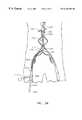
- FIGS. 3A and 3Bare schematic illustrations of the process of introducing self-expanding prosthesis employing the apparatus of FIG. 1;
- FIG. 4is a top view of a stent graft disposed on the distal portion of the apparatus of FIG. 1;
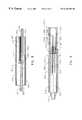
- FIG. 5is a partially sectioned side view of the lead element of the apparatus of FIG. 1;
- FIG. 6is a front view of a stent graft maintained in a compressed state by the bound sheath of the apparatus of FIG. 1;
- FIGS. 7 and 7Aare partially sectioned side views of respective embodiments of the follower element of the apparatus of FIG. 1;
- FIG. 8is a sectional view of a bifurcated prosthesis, and cooperating sheaths
- FIG. 9is a partially sectioned top view of the distal portion of one embodiment of an apparatus for introducing a bifurcated self expanding prosthesis in accordance with one aspect of the present invention, with portions of the prosthesis removed for clarity;
- FIG. 10is a partially sectioned top view of the apparatus of FIG. 9;
- FIG. 11is a schematic illustration of the base of one embodiment of a follower element suitable for use in the apparatus of FIG. 9;
- FIG. 12is a partially sectioned top view of the distal portion of an alternative embodiment of apparatus for introducing a bifurcated self expanding prosthesis in accordance with one aspect of the present invention
- FIG. 13is a schematic illustration of the base of one embodiment of a lead element suitable for use in the apparatus of FIG. 12;
- FIG. 14is a schematic top view of the apparatus of FIG. 9 with the contralateral leg of a bifurcated stent graft partially deployed;
- FIGS. 15-17are schematic illustrations of the process of introducing a bifurcated self-expanding prosthesis.
- an introducer apparatus 100 for deploying a self expanding prosthesis 102 into a body lumensuitably comprises: an elongated catheter 104 , a sheath 110 , a flexible elongated release element (e.g., release wire) 112 , and, preferably, a lead element 106 , a follower element 108 , and respective retaining rings 114 .
- prosthesis 102is releasably disposed on the distal end of catheter 104 in a compressed state between lead element 106 and follower element 108 with catheter 104 passing through an internal lumen 202 (FIG. 2) of the prosthesis.
- Lead element 106 and follower element 108fix the axial position of prosthesis 102 on catheter 104 .
- Sheath 110suitably a sheet of biocompatible material, e.g., PTFE, is disposed about (e.g., surrounding) at least a portion of prosthesis 102 . As best seen in FIGS.
- respective opposing edges 502 and 504 of sheath 110are, releasably secured (e.g., pinned or bound) together by release element 112 , maintaining prosthesis 102 in a compressed state.
- Release element 112suitably passes through a passageway in follower element 108 and extends exteriorly of, and generally along, catheter 104 towards the proximal end of catheter 104 .
- retaining rings 114if employed, provide relative position and between release element 112 and catheter 104 .
- prosthesis 102is deployed by puncturing the skin at a convenient (minimally traumatic) entry point 302 , and entering a body lumen e.g., a blood vessel such as femoral artery 304 , with a hollow needle (not shown).
- An elongated guide element (guide wire) 306is typically passed into body lumen 304 , extending into lumen 304 beyond the point at which prosthesis 102 is to be located, e.g., just below renal arteries 305 (the infrarenal portion of the aortic artery).
- Such guide wirestend to be relatively stiff, and facilitate control of the vessel and removal or lessening of sharp bends.
- the guidewireis typically employed to accommodate introduction of a variety of devices into the vessel such as, for example, an angiographic catheter, or balloon catheter.
- a vessel dilator(not shown) is then suitably employed to expand entry point 302 and body lumen 304 to facilitate introduction of introducer 100 .
- a hollow entry sheath 308is then suitably introduced into body lumen 304 over guide wire 306 and the dilator removed. Entry sheath 308 is used to shutoff blood flow from the vessel with a valve.
- Catheter 104(with prosthesis 102 on the distal end thereof, and release element 112 running along the exterior thereof) is then inserted through entry sheath 308 and advanced along guide wire 306 (or otherwise maneuvered through lumen 304 ) to the site where prosthesis 102 is to be deployed.
- introducer 100suitably travels directly within the interior of body lumen 304 , without the necessity of an exterior catheter; entry sheath 308 need only extend through the skin into the vessel.
- Release element 112extends outward from entry sheath 308 , and is suitably terminated at its proximal end with a tab or pull ring 310 .
- release element 112is pulled in the proximal direction and extracted, releasing sheath 110 so that prosthesis 102 expands.
- Introducer 100may then be extracted by passing through the lumen of the expanded prosthesis, the interior of body lumen 304 , and entry sheath 308 .
- Sheath 110may be left in the patient, held in place by the radial force of prosthesis 102 or extracted with introducer 100 , if desired. If sheath 110 is to be extracted, an attachment to e.g., follower element 108 is effected in a manner that does not interfere with the expansion of prosthesis 102 upon release of sheath 110 .
- introducer 100can accommodate substantially any manner of self expanding prosthesis 102 , having an internal lumen 202 , of a diameter sufficient to accommodate catheter 104 when in a compressed state, and to permit extraction of apparatus 100 when in an expanded state.
- Prosthesis 102is suitably a stent-graft, including self-expanding stent portions 116 , and a biocompatible cover 118 .
- introducer 100is particularly suited for deploying bifurcated stent grafts.
- Catheter 104may comprise any flexible tubing suitable for intraluminal maneuvering of prosthesis 102 into a desired position within the body lumen.
- Catheter 104is suitably of a predetermined outer diameter, (capable of being accommodated within prosthesis lumen 202 when prosthesis 102 is compressed), and includes an internal (preferably co-axial) lumen.
- a suitable guide elemente.g., wire
- the catheterslides along guide element to facilitate maneuvering prosthesis 102 into position.
- Lead element 106 and follower element 108are employed to fix the axial position of prosthesis 102 on catheter 104 and are suitably configured to facilitate insertion and extraction of introducer 100 into and from body lumen 304 .
- Lead element 106also facilitates access and guiding of the catheter through lumens that are not always round and disease-free.
- Follower element 108keeps the stent or stent graft in its axial position while the release wire is being removed.
- Elements 106 and 108may be formed of any commonly known medical grade plastic, metal, or combination thereof and preferably is radio opaque. Referring to FIG.
- lead element 106suitably comprises a body 602 , with a distal (front) end 604 and proximal end (base) 606 , an axial through—bore 608 , and, preferably, a retaining bore 610 adapted to receive the distal end of release element 112 .
- Lead element 106is suitably tapered in the distal direction, i.e., body 602 is suitably generally frustro-conical in shape, with rounded forward corners 612 to facilitate insertion.
- Distal end 604is suitably of the diameter sufficient to comfortably slide through the appropriate size vessel entry sheath 308 .
- Lead element 106suitably also includes rounded rear edges 614 to facilitate extraction.
- the diameter of base 606is suitably chosen to be just larger than the outer diameter of sheath 110 , with prosthesis 102 maintained in a compressed state on catheter 104 .
- the maximum diameter (e.g. rear edge 614 ) of lead element 602suitably ranges in diameters from 5 French to 9 French for peripheral and coronary applications, and from 12 French to 24 French for iliac and aortic applications.
- Elements 106 and 108may be attached to catheter 104 by compression fit, molding, or by any other commonly known bonding method.
- follower element 108is suitably and substantially identical to lead element 106 , but is reversed in direction on catheter 104 , i.e., is tapered in the proximal direction to facilitate extraction, and includes a channel or passageway for accommodating passage of release element 112 .
- element 108suitably comprises a body 702 , with a proximal (small rear) end 704 and distal end (base) 706 , an axial through—bore 708 , and a channel or passageway 710 adapted to accommodate passage of release element 112 .
- the peripheral edges 712 and 714 of follower element 108and suitably rounded to facilitate extraction.
- a suitable thread or wire 720may be stitched through sheath 110 in the vicinity of the proximal edge of sheath 110 , and fastened to a follower element 108 a suitable mechanism, e.g. passed through a channel 722 in follower element 108 , through apertures in a suitable washer 724 , and tied off (knot generally indicated as 726 ). Washer 724 and knot 726 are suitably disposed in a recess 728 in the sidewall of follower element 108 to facilitate extraction of apparatus 100 after deployment of prosthesis 102 .
- Sheath 110is suitably formed of a sheet of relatively thin and flexible biocompatible material, such as PTFE, FEP, or a combination thereof, having a length corresponding to the length of the prosthesis, and a width bound by first and second opposing edges generally corresponding to the circumference of the compressed prosthesis.
- the material forming sheath 110is suitably as thin as possible to provide a low profile, while still sufficiently strong to retain prosthesis 102 in its compressed state.
- sheath 110is suitably formed of laminated expanded PTFE of a thickness in the range of e.g., 0.002-0.01 in., and preferably 0.003 to 0.006 in.
- introducer 100suitably travels directly within the interior of body lumen 304 , without the necessity of an exterior catheter. This is particularly advantageous in a number of respects: entry sheath 308 need only extend through the skin into the vessel, the profile of the overall device traversing the lumen is minimized, and the axial flexibility of the stent or stent graft is not compromised by an external sheath.
- Introducer 100is particularly suited for deploying multi-limbed prostheses, such as bifurcated stent grafts often employed in connection with treatment of the infrarenal portion of the aortic artery where it bifurcates to the common iliac arteries.
- the trunk and each limb of the prosthesiswould employ a separate sheath, and release wire.
- the release wire for the trunk and one legwould run in parallel in the axial direction.
- the release wire for the contralateral limb(s)would traverse the juncture bend so that they are, in effect, pulled from the front (distal direction) (rather than pulled from the rear (proximal direction) as in the case of the trunk and first leg).
- Such a procedureis particularly advantageous in that it requires only a single catheterization, and the trunk and respective legs can be released in any order.
- a bifurcated stent graft 800suitably comprises a main body 802 , a first (ipsilateral) leg 804 and second (contralateral) leg 806 , each including an interior passageway, 808 , 810 , and 812 , respectively.
- Interior passageways 810 and 812 of the first and second legs 804 and 806communicate with the interior passageway 808 of main body 802 .
- a separate releasable sheathis provided for each portion of prosthesis 800 to maintain that portion of the prosthesis in a radially compressed state, e.g., a first sheath 814 is analogous to sheath 110 , which is disposed about (e.g., surrounds) main body 802 , a second sheath 816 surrounds leg 804 , and a third sheath 818 surrounds leg 806 . As best seen in FIG.
- a separate release elementis provided for each sheath: the respective opposing edges sheaths 814 , 816 , and 818 are pinned (threaded, bound) together to form respective tubes surrounding the associated portions of prosthesis 800 by an elongated release elements, e.g., wire, 902 ; 904 ; and 906 .
- release elements 902 and 904can be combined as a single release element for both main body sheath 814 and sheath 816 for ipsilateral leg 804 .
- Intraluminal deploymentis typically effected using a delivery catheter 910 suitably comprising an outer (sheath) tube 912 and coaxial inner (plunger) tube 914 arranged for relative axial movement.
- a delivery catheter 910suitably comprising an outer (sheath) tube 912 and coaxial inner (plunger) tube 914 arranged for relative axial movement.
- prosthesis 800(with sheaths 814 , 816 , and 818 in place) is compressed and disposed within the distal end of the outer catheter tube 912 in front of inner tube 914 .
- inner tube 914may be omitted.
- suitable passageways 1102 , 1104 , 1106 and 1108are provided in follower element 108 through which release elements 902 - 906 are journaled.
- Passageways 1102 - 1106may open along one edge into axial bore 708 , i.e., comprise channels molded or otherwise formed in the periphery of bore 708 , or may comprise separate passageways.
- catheter 104The distal end of catheter 104 is passed through interior passageway 810 of ipsilateral leg 804 , and interior passageway 808 of main body 802 .
- Sheaths 814 and 816thus hold main body 802 and ipsilateral leg 804 in a radially contracted state on catheter 104 , and sheath 818 maintains contralateral leg 806 in a radially contracted state.
- prosthesis 800(with sheaths 814 , 816 , and 818 in place) is compressed and disposed within the distal end of the outer catheter tube 912 in front of inner tube 914 .
- Outer sheath 912 of delivery catheter 910thus maintains contralateral leg 806 and sheath 818 compressed against ipsilateral leg 806 and catheter 104 until prosthesis 800 is deployed.
- Release element 902associated with main body 802 , suitably approaches (enters) sheath 814 from the rear (proximal end), and extends toward the front (distal end), so that it is withdrawable in the proximal direction. Release element 902 extends from the rear (proximal end) of sheath 814 , passes over sheath 816 (surrounding first leg 804 of endoprosthesis 800 ) through e.g., passageway 1102 in follower element 108 and extends the toward the proximal end of catheter 104 .
- Release element 904associated with the ipsilateral leg 804 , likewise suitably approaches (enters) sheath 814 from the rear (proximal end), and extends toward the front (distal end), so that it is withdrawable in the proximal direction. Release element 904 extends from the rear (proximal end) of sheath 814 , passes through e.g., passageway 1104 in follower element 108 and toward the proximal end of catheter 104 .
- Release element 906associated with contralateral leg 806 , arranged to be withdrawn from sheath 818 in the distal direction, i.e., approaches sheath 818 from the front (distal end), and extends toward the rear (proximal end). Release element 906 extends from the front (distal end) of sheath 818 is routed across the juncture between the endoprosthesis legs, passes over sheath 816 (which surrounds first leg 804 of endoprosthesis 800 ) through passageway 1106 in follower element 108 and extends the toward the proximal end of the catheter.
- passageways through follower element 108can be implemented in any conventional manner, including through bores and channels created by any of a number of well know methods including drilling, laser cutting, molding or EDM.
- one or more (e.g., all) of release wires 902 - 906may approach their associated sheath from the front (distal end), and extend toward the rear (proximal end) of the sheath.
- the release wireswould extend from the front (distal end) of the respective sheath to lead cone 106 , then in a proximal direction through the interior of catheter 104 .
- Lead cone 106would suitably include grooves or passageways 1304 - 1308 to facilitate entry of the release wires into the interior of catheter 104 .
- Intraluminal deploymentis typically effected using delivery catheter 910 .
- prosthesis 800(with sheaths 814 , 816 , and 818 in place) is compressed and disposed within the distal end of the outer catheter tube 912 in front of inner tube 914 . Contralateral leg 806 and sheath 818 are thus compressed against ipsilateral leg 806 and catheter 104 until prosthesis 800 is deployed.
- Delivery catheter 910is maneuvered, typically routed though a lumen (e.g., vessel), until the end of catheter 910 (and thus prosthesis 800 ) is positioned in the vicinity of the intended treatment site.
- Inner tube 914is then held stationary and outer tube 912 is withdrawn.
- Inner tube 914prevents prosthesis 800 from being withdrawn with outer tube 912 , so that, as outer tube 912 is withdrawn, prosthesis 800 (with sheaths 814 , 816 , and 818 in place) is released with the interior of the lumen.
- the subject's skinis punctured at entry point 302 , to access a body lumen e.g., a blood vessel such as the femoral artery 304 .
- a body lumene.g., a blood vessel such as the femoral artery 304 .
- the procedureis minimally invasive in that only a single puncture is required.
- elongated guide element (guide wire) 306is suitably passed into body lumen 304 , extending into lumen 304 beyond the anatomical bifurcation (generally indicated as 1500 ) at which prosthesis 800 is to be located.
- Entry point 302 and body lumen 304are suitably expanded with a vessel dilator (not shown) to facilitate introduction of introducer 100 , entry sheath 308 introduced into body lumen 304 over guide wire 306 and the dilator removed.
- delivery catheter 910 with prosthesis 800 disposed in the distal end thereof, and containing catheter 104 (and release elements 902 , 904 and 906 )is then inserted through entry sheath 308 and advanced along wire guide 306 (or otherwise maneuvered through lumen 304 ) to position prosthesis 800 at a point beyond anatomical bifurcation 1500 .
- Delivery catheter 910 , release elements 902 , 904 , and 906 , interior catheter 104 and guide wire 306all suitably extend outward from entry sheath 308 .
- outer tube 912 of delivery catheter 910is withdrawn, with inner tube 914 held stationary such that prosthesis 800 is released into vessel 304 .
- Contralateral leg 806(still compressed by sheath 818 ) is thus released from ipsilateral leg 804 and catheter 104 .
- contralateral leg 806 and sheath 818in effect, expand, creating outward torque and, causing leg 806 (still compressed by sheath 818 ) to move transversely from ipsilateral leg 804 and catheter 104 .
- Delivery catheter 910may then be fully withdrawn, and discarded.
- catheter 104is then pulled back, causing prosthesis 800 to retreat along body lumen 304 , such that contralateral leg 806 enters the contralateral branch of the body lumen from the aorta.
- Endoprosthesis 800is suitably positioned with the main body 808 located where desired below (but not covering) renal arteries 305 .
- release elements 902 , 904 , and 906are pulled in the proximal direction and extracted, releasing sheaths 814 , 816 , and 818 so that body 802 and legs 804 and 806 of prosthesis 800 expand into contact with the walls of the body lumen.
- Release elements 902 , 904 , and 906can be extracted in whatever order is most appropriate in the particular deployment desired based on the vessel anatomy.
- Introducer 100may then be extracted, passing through the lumen of the expanded body 802 and ipsilateral leg 804 of prosthesis 800 , the interior of body lumen 304 , and entry sheath 308 .
- Sheaths 814 , 816 , and 818may be left in the patient, held in place by the radial force of prosthesis 800 or extracted with introducer 100 , as desired. If one or more of sheaths 814 , 816 , and 818 is to be extracted, an attachment to e.g., follower element 108 is effected in a manner that does not interfere with the expansion of prosthesis 800 upon release of the sheath by providing capture wires that are attached to one comer of each of sheaths 814 , 816 , and 818 . These wires may simply be pulled, after its corresponding release wire has been pulled, to slide the sheath around the deployed stent or stent graft and remove it through the vessel entry sheath 308 .
Landscapes
- Health & Medical Sciences (AREA)
- Engineering & Computer Science (AREA)
- Biomedical Technology (AREA)
- Cardiology (AREA)
- Oral & Maxillofacial Surgery (AREA)
- Transplantation (AREA)
- Heart & Thoracic Surgery (AREA)
- Vascular Medicine (AREA)
- Life Sciences & Earth Sciences (AREA)
- Animal Behavior & Ethology (AREA)
- General Health & Medical Sciences (AREA)
- Public Health (AREA)
- Veterinary Medicine (AREA)
- Prostheses (AREA)
- Media Introduction/Drainage Providing Device (AREA)
Abstract
Description
Claims (23)
Priority Applications (3)
| Application Number | Priority Date | Filing Date | Title |
|---|---|---|---|
| US09/401,599US6183481B1 (en) | 1999-09-22 | 1999-09-22 | Delivery system for self-expanding stents and grafts |
| AU77083/00AAU7708300A (en) | 1999-09-22 | 2000-09-22 | Delivery system for self-expanding stents and grafts |
| PCT/US2000/025969WO2001021104A1 (en) | 1999-09-22 | 2000-09-22 | Delivery system for self-expanding stents and grafts |
Applications Claiming Priority (1)
| Application Number | Priority Date | Filing Date | Title |
|---|---|---|---|
| US09/401,599US6183481B1 (en) | 1999-09-22 | 1999-09-22 | Delivery system for self-expanding stents and grafts |
Publications (1)
| Publication Number | Publication Date |
|---|---|
| US6183481B1true US6183481B1 (en) | 2001-02-06 |
Family
ID=23588399
Family Applications (1)
| Application Number | Title | Priority Date | Filing Date |
|---|---|---|---|
| US09/401,599Expired - Fee RelatedUS6183481B1 (en) | 1999-09-22 | 1999-09-22 | Delivery system for self-expanding stents and grafts |
Country Status (3)
| Country | Link |
|---|---|
| US (1) | US6183481B1 (en) |
| AU (1) | AU7708300A (en) |
| WO (1) | WO2001021104A1 (en) |
Cited By (148)
| Publication number | Priority date | Publication date | Assignee | Title |
|---|---|---|---|---|
| US20020016597A1 (en)* | 2000-08-02 | 2002-02-07 | Dwyer Clifford J. | Delivery apparatus for a self-expanding stent |
| US6500202B1 (en) | 1998-12-11 | 2002-12-31 | Endologix, Inc. | Bifurcation graft deployment catheter |
| US20030004560A1 (en)* | 2001-04-11 | 2003-01-02 | Trivascular, Inc. | Delivery system and method for bifurcated graft |
| US6508835B1 (en) | 1998-12-11 | 2003-01-21 | Endologix, Inc. | Endoluminal vascular prosthesis |
| WO2003020173A1 (en)* | 2001-09-04 | 2003-03-13 | Graeme Cocks | A stent |
| US20030144671A1 (en)* | 1998-09-30 | 2003-07-31 | Brooks Christopher J. | Delivery mechanism for implantable stents-grafts |
| US6602280B2 (en) | 2000-02-02 | 2003-08-05 | Trivascular, Inc. | Delivery system and method for expandable intracorporeal device |
| US20030163156A1 (en)* | 2002-02-28 | 2003-08-28 | Stephen Hebert | Guidewire loaded stent for delivery through a catheter |
| US6660030B2 (en) | 1998-12-11 | 2003-12-09 | Endologix, Inc. | Bifurcation graft deployment catheter |
| US6733521B2 (en) | 2001-04-11 | 2004-05-11 | Trivascular, Inc. | Delivery system and method for endovascular graft |
| US6733523B2 (en) | 1998-12-11 | 2004-05-11 | Endologix, Inc. | Implantable vascular graft |
| US6743219B1 (en) | 2000-08-02 | 2004-06-01 | Cordis Corporation | Delivery apparatus for a self-expanding stent |
| US20040106974A1 (en)* | 2002-06-28 | 2004-06-03 | Cook Incorporated | Thoracic introducer |
| US20040138734A1 (en)* | 2001-04-11 | 2004-07-15 | Trivascular, Inc. | Delivery system and method for bifurcated graft |
| US20040167618A1 (en)* | 1999-03-11 | 2004-08-26 | Shaolian Samuel M. | Graft deployment system |
| US20040193178A1 (en)* | 2003-03-26 | 2004-09-30 | Cardiomind, Inc. | Multiple joint implant delivery systems for sequentially-controlled implant deployment |
| US20040260383A1 (en)* | 2000-03-14 | 2004-12-23 | Wolf Stelter | Endovascular stent graft |
| US20050033220A1 (en)* | 1998-09-10 | 2005-02-10 | Percardia, Inc. | Left ventricular conduit with blood vessel graft |
| US20050038495A1 (en)* | 2003-08-16 | 2005-02-17 | Trevor Greenan | Double sheath deployment system |
| US20050049674A1 (en)* | 2003-09-03 | 2005-03-03 | Berra Humberto A. | Stent graft |
| US20050049667A1 (en)* | 2003-09-03 | 2005-03-03 | Bolton Medical, Inc. | Self-aligning stent graft delivery system, kit, and method |
| US20050154443A1 (en)* | 2004-01-09 | 2005-07-14 | Rubicon Medical, Inc. | Stent delivery device |
| US6939368B2 (en) | 2002-01-17 | 2005-09-06 | Scimed Life Systems, Inc. | Delivery system for self expanding stents for use in bifurcated vessels |
| US20050209675A1 (en)* | 2004-03-02 | 2005-09-22 | Ton Dai T | Corewire actuated delivery system with fixed distal stent-carrying extension |
| US6951572B1 (en) | 1997-02-20 | 2005-10-04 | Endologix, Inc. | Bifurcated vascular graft and method and apparatus for deploying same |
| US20050273162A1 (en)* | 2002-02-07 | 2005-12-08 | Sentient Engineering & Technology, L.L.C. | Apparatus and methods for conduits and materials |
| US20060085057A1 (en)* | 2004-10-14 | 2006-04-20 | Cardiomind | Delivery guide member based stent anti-jumping technologies |
| US20060111771A1 (en)* | 2003-03-26 | 2006-05-25 | Ton Dai T | Twist-down implant delivery technologies |
| US20060136035A1 (en)* | 2004-12-20 | 2006-06-22 | Vascular Architects, Inc. A Delaware Corporation | Coiled endoluminal prosthesis system and delivery catheter |
| US20060136034A1 (en)* | 2004-12-20 | 2006-06-22 | Vascular Architects, Inc. | Delivery catheter and method |
| US20060136033A1 (en)* | 2004-12-20 | 2006-06-22 | Vascular Architects, Inc. | Coiled stent delivery system and method |
| US20070005129A1 (en)* | 2000-02-28 | 2007-01-04 | Christoph Damm | Anchoring system for implantable heart valve prostheses |
| EP1745761A1 (en) | 2000-08-23 | 2007-01-24 | LeMaitre Acquisition LLC | Method of manufacturing custom intravascular devices |
| US20070021820A1 (en)* | 2005-07-21 | 2007-01-25 | Med Institute, Inc. | Stent delivery system with a retention wire |
| US7169170B2 (en) | 2002-02-22 | 2007-01-30 | Cordis Corporation | Self-expanding stent delivery system |
| US20070043381A1 (en)* | 2005-08-19 | 2007-02-22 | Icon Medical Corp. | Medical device deployment instrument |
| US20070073379A1 (en)* | 2005-09-29 | 2007-03-29 | Chang Jean C | Stent delivery system |
| US20070100415A1 (en)* | 2005-11-02 | 2007-05-03 | David Licata | Indirect-release electrolytic implant delivery systems |
| US20070100440A1 (en)* | 2005-10-28 | 2007-05-03 | Jen.Cardiotec Gmbh | Device for the implantation and fixation of prosthetic valves |
| US20070135889A1 (en)* | 2003-09-03 | 2007-06-14 | Bolton Medical, Inc. | Lumen repair device with capture structure |
| US20070142906A1 (en)* | 2005-11-04 | 2007-06-21 | Jen. Cardiotec Gmbh | Self-expandable medical instrument for treating defects in a patient's heart |
| EP1813232A1 (en) | 2006-01-31 | 2007-08-01 | Cordis Corporation | Deployment catheter for medical implant devices |
| US20070198078A1 (en)* | 2003-09-03 | 2007-08-23 | Bolton Medical, Inc. | Delivery system and method for self-centering a Proximal end of a stent graft |
| US20070203563A1 (en)* | 2006-02-13 | 2007-08-30 | Stephen Hebert | System for delivering a stent |
| US20070225789A1 (en)* | 2006-03-22 | 2007-09-27 | Kavanagh Joseph T | Method of stenting with minimal diameter guided delivery systems |
| US20070299497A1 (en)* | 1998-12-11 | 2007-12-27 | Endologix, Inc. | Implantable vascular graft |
| US20080071343A1 (en)* | 2006-09-15 | 2008-03-20 | Kevin John Mayberry | Multi-segmented graft deployment system |
| US20080082159A1 (en)* | 2006-09-28 | 2008-04-03 | Cook Incorporated | Stent for Endovascular Procedures |
| WO2008066923A1 (en)* | 2006-11-30 | 2008-06-05 | William Cook Europe Aps | Implant release mechanism |
| US20080172122A1 (en)* | 2007-01-12 | 2008-07-17 | Mayberry Kevin J | Dual concentric guidewire and methods of bifurcated graft deployment |
| US20080221666A1 (en)* | 2006-12-15 | 2008-09-11 | Cardiomind, Inc. | Stent systems |
| US20080255654A1 (en)* | 2007-03-22 | 2008-10-16 | Bay Street Medical | System for delivering a stent |
| US20080255661A1 (en)* | 2007-04-13 | 2008-10-16 | Helmut Straubinger | Medical device for treating a heart valve insufficiency or stenosis |
| US20080255660A1 (en)* | 2007-04-13 | 2008-10-16 | Volker Guyenot | Medical device for treating a heart valve insufficiency |
| US20080275540A1 (en)* | 2005-11-09 | 2008-11-06 | Ning Wen | Artificial Heart Valve Stent and Weaving Method Thereof |
| US20080300667A1 (en)* | 2007-05-31 | 2008-12-04 | Bay Street Medical | System for delivering a stent |
| US20090024205A1 (en)* | 2007-07-19 | 2009-01-22 | Bay Street Medical | Radially Expandable Stent |
| US20090048656A1 (en)* | 2005-11-09 | 2009-02-19 | Ning Wen | Delivery Device for Delivering a Self-Expanding Stent |
| US20090054968A1 (en)* | 2001-08-03 | 2009-02-26 | Jenavalve Technology Inc. | Implant implantation unit and procedure for implanting the unit |
| US20090099640A1 (en)* | 2006-03-30 | 2009-04-16 | Ning Weng | Axial Pullwire Tension Mechanism for Self-Expanding Stent |
| US20090138023A1 (en)* | 2005-12-13 | 2009-05-28 | Johnson Kirk L | Actuator Handle for Use With Medical Device Deployment Systems |
| US20090171447A1 (en)* | 2005-12-22 | 2009-07-02 | Von Segesser Ludwig K | Stent-valves for valve replacement and associated methods and systems for surgery |
| US20090216313A1 (en)* | 2008-02-26 | 2009-08-27 | Helmut Straubinger | Stent for the positioning and anchoring of a valvular prosthesis |
| US20090216312A1 (en)* | 2008-02-26 | 2009-08-27 | Helmut Straubinger | Stent for the Positioning and Anchoring of a Valvular Prosthesis in an Implantation Site in the Heart of a Patient |
| US20090234443A1 (en)* | 2005-01-20 | 2009-09-17 | Ottma Ruediger | Catheter for the Transvascular Implantation of Prosthetic Heart Valves |
| US20090281611A1 (en)* | 2004-03-02 | 2009-11-12 | Cardiomind, Inc. | Sliding restraint stent delivery systems |
| US20090287145A1 (en)* | 2008-05-15 | 2009-11-19 | Altura Interventional, Inc. | Devices and methods for treatment of abdominal aortic aneurysms |
| US20100016943A1 (en)* | 2001-12-20 | 2010-01-21 | Trivascular2, Inc. | Method of delivering advanced endovascular graft |
| US20100030318A1 (en)* | 2003-09-03 | 2010-02-04 | Bolton Medical, Inc. | Dual Capture Device for Stent Graft Delivery System and Method for Capturing a Stent Graft |
| US7785361B2 (en) | 2003-03-26 | 2010-08-31 | Julian Nikolchev | Implant delivery technologies |
| US20100234932A1 (en)* | 2009-03-13 | 2010-09-16 | Bolton Medical, Inc. | System and method for deploying an endoluminal prosthesis at a surgical site |
| US20100280588A1 (en)* | 2009-05-01 | 2010-11-04 | Endologix, Inc. | Percutaneous method and device to treat dissections |
| US20100292780A1 (en)* | 2009-05-15 | 2010-11-18 | Helmut Straubinger | Device for compressing a stent as well as system and method for loading a stent into a medical delivery system |
| US20100331948A1 (en)* | 2009-06-26 | 2010-12-30 | Cardiomind, Inc. | Implant delivery apparatus and methods with electrolytic release |
| US20110022157A1 (en)* | 2007-10-25 | 2011-01-27 | Jacques Essinger | Stents, Valved-Stents, and Methods and Systems for Delivery Thereof |
| US20110066220A1 (en)* | 2002-02-07 | 2011-03-17 | Sentient Engineering & Technology, L.L.C. | Apparatus and methods for conduits and materials |
| US20110082552A1 (en)* | 2009-04-27 | 2011-04-07 | Wistrom Elizabeth V | Prosthetic Intervertebral Discs Implantable By Minimally Invasive Surgical Techniques |
| US20110130825A1 (en)* | 2009-12-01 | 2011-06-02 | Altura Medical, Inc. | Modular endograft devices and associated systems and methods |
| US20110208290A1 (en)* | 2008-02-26 | 2011-08-25 | Helmut Straubinger | Stent for the positioning and anchoring of a valvular prosthesis in an implantation site in the heart of a patient |
| US20110218617A1 (en)* | 2010-03-02 | 2011-09-08 | Endologix, Inc. | Endoluminal vascular prosthesis |
| US20110224772A1 (en)* | 2008-04-11 | 2011-09-15 | Endologix, Inc. | Bifurcated graft deployment systems and methods |
| US8066755B2 (en) | 2007-09-26 | 2011-11-29 | Trivascular, Inc. | System and method of pivoted stent deployment |
| US8083789B2 (en) | 2007-11-16 | 2011-12-27 | Trivascular, Inc. | Securement assembly and method for expandable endovascular device |
| US8118856B2 (en) | 2009-07-27 | 2012-02-21 | Endologix, Inc. | Stent graft |
| US20120065644A1 (en)* | 2010-09-15 | 2012-03-15 | Abbott Cardiovascular Systems, Inc. | Stent deployment system with retractable shealth |
| US20120101563A1 (en)* | 2009-05-26 | 2012-04-26 | Qing Zhu | Delivery system for branched stent graft |
| US8167925B2 (en) | 1999-03-11 | 2012-05-01 | Endologix, Inc. | Single puncture bifurcation graft deployment system |
| US20120172968A1 (en)* | 2006-04-27 | 2012-07-05 | William A. Cook Australila Pty. Ltd. | Controlled sequential deployment |
| US8216295B2 (en) | 2008-07-01 | 2012-07-10 | Endologix, Inc. | Catheter system and methods of using same |
| US8226701B2 (en) | 2007-09-26 | 2012-07-24 | Trivascular, Inc. | Stent and delivery system for deployment thereof |
| US20120232635A1 (en)* | 2011-03-08 | 2012-09-13 | Cook Medical Technologies Llc | Introducer assembly and carrier element for a medical device |
| US8328861B2 (en) | 2007-11-16 | 2012-12-11 | Trivascular, Inc. | Delivery system and method for bifurcated graft |
| US8398704B2 (en) | 2008-02-26 | 2013-03-19 | Jenavalve Technology, Inc. | Stent for the positioning and anchoring of a valvular prosthesis in an implantation site in the heart of a patient |
| US8491646B2 (en) | 2009-07-15 | 2013-07-23 | Endologix, Inc. | Stent graft |
| US8652193B2 (en) | 2005-05-09 | 2014-02-18 | Angiomed Gmbh & Co. Medizintechnik Kg | Implant delivery device |
| US8663309B2 (en) | 2007-09-26 | 2014-03-04 | Trivascular, Inc. | Asymmetric stent apparatus and method |
| US8696731B2 (en) | 2011-06-10 | 2014-04-15 | DePuy Synthes Products, LLC | Lock/floating marker band on pusher wire for self-expanding stents or medical devices |
| US8808350B2 (en) | 2011-03-01 | 2014-08-19 | Endologix, Inc. | Catheter system and methods of using same |
| USRE45130E1 (en) | 2000-02-28 | 2014-09-09 | Jenavalve Technology Gmbh | Device for fastening and anchoring cardiac valve prostheses |
| US20140257456A1 (en)* | 2013-03-05 | 2014-09-11 | Cook Medical Technologies Llc | Inner catheter with a pusher band |
| US8858613B2 (en) | 2010-09-20 | 2014-10-14 | Altura Medical, Inc. | Stent graft delivery systems and associated methods |
| US8876876B2 (en) | 2008-06-06 | 2014-11-04 | Back Bay Medical Inc. | Prosthesis and delivery system |
| US20150005808A1 (en)* | 2013-06-26 | 2015-01-01 | W. L. Gore & Associates, Inc. | Medical device deployment system |
| US8945202B2 (en) | 2009-04-28 | 2015-02-03 | Endologix, Inc. | Fenestrated prosthesis |
| US8961587B2 (en) | 2009-03-18 | 2015-02-24 | Microport Endovascular (Shanghai) Co., Ltd. | Branched stent graft |
| US8992595B2 (en) | 2012-04-04 | 2015-03-31 | Trivascular, Inc. | Durable stent graft with tapered struts and stable delivery methods and devices |
| US8998970B2 (en) | 2012-04-12 | 2015-04-07 | Bolton Medical, Inc. | Vascular prosthetic delivery device and method of use |
| US20150134056A1 (en)* | 2008-02-29 | 2015-05-14 | The Florida International University Board Of Trustees | Catheter deliverable artificial multi-leaflet heart valve prosthesis and intravascular delivery system for a catheter deliverable heart valve prosthesis |
| US9132025B2 (en) | 2012-06-15 | 2015-09-15 | Trivascular, Inc. | Bifurcated endovascular prosthesis having tethered contralateral leg |
| US9168130B2 (en) | 2008-02-26 | 2015-10-27 | Jenavalve Technology Gmbh | Stent for the positioning and anchoring of a valvular prosthesis in an implantation site in the heart of a patient |
| US9295551B2 (en) | 2007-04-13 | 2016-03-29 | Jenavalve Technology Gmbh | Methods of implanting an endoprosthesis |
| US9364314B2 (en) | 2008-06-30 | 2016-06-14 | Bolton Medical, Inc. | Abdominal aortic aneurysms: systems and methods of use |
| US9393100B2 (en) | 2010-11-17 | 2016-07-19 | Endologix, Inc. | Devices and methods to treat vascular dissections |
| US9439751B2 (en) | 2013-03-15 | 2016-09-13 | Bolton Medical, Inc. | Hemostasis valve and delivery systems |
| US9498363B2 (en) | 2012-04-06 | 2016-11-22 | Trivascular, Inc. | Delivery catheter for endovascular device |
| US9510947B2 (en) | 2011-10-21 | 2016-12-06 | Jenavalve Technology, Inc. | Catheter system for introducing an expandable heart valve stent into the body of a patient |
| US9597182B2 (en) | 2010-05-20 | 2017-03-21 | Jenavalve Technology Inc. | Catheter system for introducing an expandable stent into the body of a patient |
| US9737426B2 (en) | 2013-03-15 | 2017-08-22 | Altura Medical, Inc. | Endograft device delivery systems and associated methods |
| US9744031B2 (en) | 2010-05-25 | 2017-08-29 | Jenavalve Technology, Inc. | Prosthetic heart valve and endoprosthesis comprising a prosthetic heart valve and a stent |
| US9867699B2 (en) | 2008-02-26 | 2018-01-16 | Jenavalve Technology, Inc. | Endoprosthesis for implantation in the heart of a patient |
| US9867694B2 (en) | 2013-08-30 | 2018-01-16 | Jenavalve Technology Inc. | Radially collapsible frame for a prosthetic valve and method for manufacturing such a frame |
| US9877857B2 (en) | 2003-09-03 | 2018-01-30 | Bolton Medical, Inc. | Sheath capture device for stent graft delivery system and method for operating same |
| US9878127B2 (en) | 2012-05-16 | 2018-01-30 | Jenavalve Technology, Inc. | Catheter delivery system for heart valve prosthesis |
| US20180071125A1 (en)* | 2016-09-09 | 2018-03-15 | Cook Medical Technologies Llc | Prosthesis deployment system and method |
| US10016292B2 (en) | 2014-04-18 | 2018-07-10 | Covidien Lp | Stent delivery system |
| US10159557B2 (en) | 2007-10-04 | 2018-12-25 | Trivascular, Inc. | Modular vascular graft for low profile percutaneous delivery |
| US10172634B1 (en) | 2017-10-16 | 2019-01-08 | Michael Bruce Horowitz | Catheter based retrieval device with proximal body having axial freedom of movement |
| US10245166B2 (en) | 2008-02-22 | 2019-04-02 | Endologix, Inc. | Apparatus and method of placement of a graft or graft system |
| US10258464B2 (en) | 2012-03-22 | 2019-04-16 | Symetis Sa | Transcatheter stent-valves |
| US10285833B2 (en) | 2012-08-10 | 2019-05-14 | Lombard Medical Limited | Stent delivery systems and associated methods |
| US10376359B2 (en) | 2009-11-02 | 2019-08-13 | Symetis Sa | Aortic bioprosthesis and systems for delivery thereof |
| US10709555B2 (en) | 2015-05-01 | 2020-07-14 | Jenavalve Technology, Inc. | Device and method with reduced pacemaker rate in heart valve replacement |
| US10716662B2 (en) | 2007-08-21 | 2020-07-21 | Boston Scientific Limited | Stent-valves for valve replacement and associated methods and systems for surgery |
| US10772717B2 (en) | 2009-05-01 | 2020-09-15 | Endologix, Inc. | Percutaneous method and device to treat dissections |
| US11065138B2 (en) | 2016-05-13 | 2021-07-20 | Jenavalve Technology, Inc. | Heart valve prosthesis delivery system and method for delivery of heart valve prosthesis with introducer sheath and loading system |
| US11129737B2 (en) | 2015-06-30 | 2021-09-28 | Endologix Llc | Locking assembly for coupling guidewire to delivery system |
| US11197754B2 (en) | 2017-01-27 | 2021-12-14 | Jenavalve Technology, Inc. | Heart valve mimicry |
| US11207176B2 (en) | 2012-03-22 | 2021-12-28 | Boston Scientific Scimed, Inc. | Transcatheter stent-valves and methods, systems and devices for addressing para-valve leakage |
| US11259945B2 (en) | 2003-09-03 | 2022-03-01 | Bolton Medical, Inc. | Dual capture device for stent graft delivery system and method for capturing a stent graft |
| US11278406B2 (en) | 2010-05-20 | 2022-03-22 | Jenavalve Technology, Inc. | Catheter system for introducing an expandable heart valve stent into the body of a patient, insertion system with a catheter system and medical device for treatment of a heart valve defect |
| US11382643B2 (en) | 2017-10-16 | 2022-07-12 | Retriever Medical, Inc. | Clot removal methods and devices with multiple independently controllable elements |
| US11406518B2 (en) | 2010-11-02 | 2022-08-09 | Endologix Llc | Apparatus and method of placement of a graft or graft system |
| US11589881B2 (en) | 2017-10-16 | 2023-02-28 | Retriever Medical, Inc. | Clot removal methods and devices with multiple independently controllable elements |
| US11596537B2 (en) | 2003-09-03 | 2023-03-07 | Bolton Medical, Inc. | Delivery system and method for self-centering a proximal end of a stent graft |
| US12121461B2 (en) | 2015-03-20 | 2024-10-22 | Jenavalve Technology, Inc. | Heart valve prosthesis delivery system and method for delivery of heart valve prosthesis with introducer sheath |
| US12171658B2 (en) | 2022-11-09 | 2024-12-24 | Jenavalve Technology, Inc. | Catheter system for sequential deployment of an expandable implant |
| EP4497420A3 (en)* | 2008-06-04 | 2025-04-02 | W. L. Gore & Associates, Inc. | Controlled deployable medical device |
| US12409055B2 (en) | 2020-06-24 | 2025-09-09 | Bolton Medical, Inc. | Anti-backspin component for vascular prosthesis delivery device |
Citations (47)
| Publication number | Priority date | Publication date | Assignee | Title |
|---|---|---|---|---|
| US3657744A (en) | 1970-05-08 | 1972-04-25 | Univ Minnesota | Method for fixing prosthetic implants in a living body |
| US3953566A (en) | 1970-05-21 | 1976-04-27 | W. L. Gore & Associates, Inc. | Process for producing porous products |
| US4140126A (en) | 1977-02-18 | 1979-02-20 | Choudhury M Hasan | Method for performing aneurysm repair |
| US4482516A (en) | 1982-09-10 | 1984-11-13 | W. L. Gore & Associates, Inc. | Process for producing a high strength porous polytetrafluoroethylene product having a coarse microstructure |
| US4544711A (en) | 1984-06-15 | 1985-10-01 | Atlantic Richfield Company | Process for making terminally functional polymers |
| US4580568A (en) | 1984-10-01 | 1986-04-08 | Cook, Incorporated | Percutaneous endovascular stent and method for insertion thereof |
| US4617932A (en) | 1984-04-25 | 1986-10-21 | Elliot Kornberg | Device and method for performing an intraluminal abdominal aortic aneurysm repair |
| US4655771A (en) | 1982-04-30 | 1987-04-07 | Shepherd Patents S.A. | Prosthesis comprising an expansible or contractile tubular body |
| US4800882A (en) | 1987-03-13 | 1989-01-31 | Cook Incorporated | Endovascular stent and delivery system |
| US4907336A (en) | 1987-03-13 | 1990-03-13 | Cook Incorporated | Method of making an endovascular stent and delivery system |
| US4955899A (en) | 1989-05-26 | 1990-09-11 | Impra, Inc. | Longitudinally compliant vascular graft |
| US5019085A (en)* | 1988-10-25 | 1991-05-28 | Cordis Corporation | Apparatus and method for placement of a stent within a subject vessel |
| US5122154A (en) | 1990-08-15 | 1992-06-16 | Rhodes Valentine J | Endovascular bypass graft |
| US5123917A (en) | 1990-04-27 | 1992-06-23 | Lee Peter Y | Expandable intraluminal vascular graft |
| US5152782A (en) | 1989-05-26 | 1992-10-06 | Impra, Inc. | Non-porous coated ptfe graft |
| WO1992019310A1 (en) | 1991-04-26 | 1992-11-12 | Advanced Coronary Technology, Inc. | Removable heat-recoverable tissue supporting device |
| US5302317A (en) | 1987-11-06 | 1994-04-12 | Hoffmann-La Roche Inc. | Halobenzene liquid crystals |
| US5316023A (en) | 1992-01-08 | 1994-05-31 | Expandable Grafts Partnership | Method for bilateral intra-aortic bypass |
| WO1995005555A1 (en) | 1993-08-18 | 1995-02-23 | W. L. Gore & Associates, Inc. | A thin-wall polytetrafluoroethylene tube |
| US5415664A (en)* | 1994-03-30 | 1995-05-16 | Corvita Corporation | Method and apparatus for introducing a stent or a stent-graft |
| US5484444A (en)* | 1992-10-31 | 1996-01-16 | Schneider (Europe) A.G. | Device for the implantation of self-expanding endoprostheses |
| US5489295A (en) | 1991-04-11 | 1996-02-06 | Endovascular Technologies, Inc. | Endovascular graft having bifurcation and apparatus and method for deploying the same |
| US5507771A (en) | 1992-06-15 | 1996-04-16 | Cook Incorporated | Stent assembly |
| US5507767A (en) | 1992-01-15 | 1996-04-16 | Cook Incorporated | Spiral stent |
| US5575816A (en) | 1994-08-12 | 1996-11-19 | Meadox Medicals, Inc. | High strength and high density intraluminal wire stent |
| US5609627A (en) | 1994-02-09 | 1997-03-11 | Boston Scientific Technology, Inc. | Method for delivering a bifurcated endoluminal prosthesis |
| US5632763A (en) | 1995-01-19 | 1997-05-27 | Cordis Corporation | Bifurcated stent and method for implanting same |
| US5639278A (en) | 1993-10-21 | 1997-06-17 | Corvita Corporation | Expandable supportive bifurcated endoluminal grafts |
| US5662713A (en) | 1991-10-09 | 1997-09-02 | Boston Scientific Corporation | Medical stents for body lumens exhibiting peristaltic motion |
| US5695517A (en) | 1994-02-10 | 1997-12-09 | Endovascular Systems, Inc. | Method and apparatus for forming an endoluminal bifurcated graft |
| US5700285A (en) | 1993-08-18 | 1997-12-23 | W. L. Gore & Associates, Inc. | Intraluminal stent graft |
| US5700269A (en) | 1995-06-06 | 1997-12-23 | Corvita Corporation | Endoluminal prosthesis deployment device for use with prostheses of variable length and having retraction ability |
| WO1998000090A2 (en) | 1996-07-03 | 1998-01-08 | Baxter International Inc. | Stented, radially expandable, tubular ptfe grafts |
| US5749880A (en) | 1995-03-10 | 1998-05-12 | Impra, Inc. | Endoluminal encapsulated stent and methods of manufacture and endoluminal delivery |
| US5755734A (en) | 1996-05-03 | 1998-05-26 | Medinol Ltd. | Bifurcated stent and method of making same |
| WO1998026731A2 (en) | 1996-12-03 | 1998-06-25 | Atrium Medical Corporation | Multi-stage prosthesis |
| US5776142A (en) | 1996-12-19 | 1998-07-07 | Medtronic, Inc. | Controllable stent delivery system and method |
| WO1998031306A1 (en) | 1997-01-17 | 1998-07-23 | Meadox Medicals, Inc. | Ptfe graft-stent composite device |
| WO1998036708A1 (en) | 1997-02-20 | 1998-08-27 | Endologix, Inc. | Bifurcated vascular graft and method and apparatus for deploying same |
| WO1998038947A1 (en) | 1997-03-05 | 1998-09-11 | Scimed Life Systems, Inc. | Conformal laminate stent device |
| US5824037A (en) | 1995-10-03 | 1998-10-20 | Medtronic, Inc. | Modular intraluminal prostheses construction and methods |
| US5833694A (en) | 1995-05-25 | 1998-11-10 | Medtronic, Inc. | Stent assembly and method of use |
| EP0893108A2 (en) | 1997-07-18 | 1999-01-27 | Gore Enterprise Holdings, Inc. | Kink-resistant stent-graft |
| US5873906A (en) | 1994-09-08 | 1999-02-23 | Gore Enterprise Holdings, Inc. | Procedures for introducing stents and stent-grafts |
| US5906641A (en) | 1997-05-27 | 1999-05-25 | Schneider (Usa) Inc | Bifurcated stent graft |
| US5906640A (en) | 1994-11-03 | 1999-05-25 | Divysio Solutions Ulc | Bifurcated stent and method for the manufacture and delivery of same |
| US6027510A (en)* | 1997-12-08 | 2000-02-22 | Inflow Dynamics Inc. | Stent delivery system |
Family Cites Families (2)
| Publication number | Priority date | Publication date | Assignee | Title |
|---|---|---|---|---|
| US5571172A (en)* | 1994-08-15 | 1996-11-05 | Origin Medsystems, Inc. | Method and apparatus for endoscopic grafting |
| US6352561B1 (en)* | 1996-12-23 | 2002-03-05 | W. L. Gore & Associates | Implant deployment apparatus |
- 1999
- 1999-09-22USUS09/401,599patent/US6183481B1/ennot_activeExpired - Fee Related
- 2000
- 2000-09-22WOPCT/US2000/025969patent/WO2001021104A1/enactiveApplication Filing
- 2000-09-22AUAU77083/00Apatent/AU7708300A/ennot_activeAbandoned
Patent Citations (52)
| Publication number | Priority date | Publication date | Assignee | Title |
|---|---|---|---|---|
| US3657744A (en) | 1970-05-08 | 1972-04-25 | Univ Minnesota | Method for fixing prosthetic implants in a living body |
| US3953566A (en) | 1970-05-21 | 1976-04-27 | W. L. Gore & Associates, Inc. | Process for producing porous products |
| US4187390A (en) | 1970-05-21 | 1980-02-05 | W. L. Gore & Associates, Inc. | Porous products and process therefor |
| US4140126A (en) | 1977-02-18 | 1979-02-20 | Choudhury M Hasan | Method for performing aneurysm repair |
| US4655771A (en) | 1982-04-30 | 1987-04-07 | Shepherd Patents S.A. | Prosthesis comprising an expansible or contractile tubular body |
| US4655771B1 (en) | 1982-04-30 | 1996-09-10 | Medinvent Ams Sa | Prosthesis comprising an expansible or contractile tubular body |
| US4482516A (en) | 1982-09-10 | 1984-11-13 | W. L. Gore & Associates, Inc. | Process for producing a high strength porous polytetrafluoroethylene product having a coarse microstructure |
| US4617932A (en) | 1984-04-25 | 1986-10-21 | Elliot Kornberg | Device and method for performing an intraluminal abdominal aortic aneurysm repair |
| US4544711A (en) | 1984-06-15 | 1985-10-01 | Atlantic Richfield Company | Process for making terminally functional polymers |
| US4580568A (en) | 1984-10-01 | 1986-04-08 | Cook, Incorporated | Percutaneous endovascular stent and method for insertion thereof |
| US4800882A (en) | 1987-03-13 | 1989-01-31 | Cook Incorporated | Endovascular stent and delivery system |
| US4907336A (en) | 1987-03-13 | 1990-03-13 | Cook Incorporated | Method of making an endovascular stent and delivery system |
| US5302317A (en) | 1987-11-06 | 1994-04-12 | Hoffmann-La Roche Inc. | Halobenzene liquid crystals |
| US5019085A (en)* | 1988-10-25 | 1991-05-28 | Cordis Corporation | Apparatus and method for placement of a stent within a subject vessel |
| US4955899A (en) | 1989-05-26 | 1990-09-11 | Impra, Inc. | Longitudinally compliant vascular graft |
| US5152782A (en) | 1989-05-26 | 1992-10-06 | Impra, Inc. | Non-porous coated ptfe graft |
| US5123917A (en) | 1990-04-27 | 1992-06-23 | Lee Peter Y | Expandable intraluminal vascular graft |
| US5122154A (en) | 1990-08-15 | 1992-06-16 | Rhodes Valentine J | Endovascular bypass graft |
| US5489295A (en) | 1991-04-11 | 1996-02-06 | Endovascular Technologies, Inc. | Endovascular graft having bifurcation and apparatus and method for deploying the same |
| WO1992019310A1 (en) | 1991-04-26 | 1992-11-12 | Advanced Coronary Technology, Inc. | Removable heat-recoverable tissue supporting device |
| US5662713A (en) | 1991-10-09 | 1997-09-02 | Boston Scientific Corporation | Medical stents for body lumens exhibiting peristaltic motion |
| US5316023A (en) | 1992-01-08 | 1994-05-31 | Expandable Grafts Partnership | Method for bilateral intra-aortic bypass |
| US5507767A (en) | 1992-01-15 | 1996-04-16 | Cook Incorporated | Spiral stent |
| US5507771A (en) | 1992-06-15 | 1996-04-16 | Cook Incorporated | Stent assembly |
| US5484444A (en)* | 1992-10-31 | 1996-01-16 | Schneider (Europe) A.G. | Device for the implantation of self-expanding endoprostheses |
| WO1995005555A1 (en) | 1993-08-18 | 1995-02-23 | W. L. Gore & Associates, Inc. | A thin-wall polytetrafluoroethylene tube |
| US5700285A (en) | 1993-08-18 | 1997-12-23 | W. L. Gore & Associates, Inc. | Intraluminal stent graft |
| US5639278A (en) | 1993-10-21 | 1997-06-17 | Corvita Corporation | Expandable supportive bifurcated endoluminal grafts |
| US5609627A (en) | 1994-02-09 | 1997-03-11 | Boston Scientific Technology, Inc. | Method for delivering a bifurcated endoluminal prosthesis |
| US5916263A (en) | 1994-02-09 | 1999-06-29 | Boston Scientific Technology, Inc. | Bifurcated endoluminal prosthesis |
| US5718724A (en) | 1994-02-09 | 1998-02-17 | Boston Scientific Technology, Inc. | Bifurcated endoluminal prosthesis |
| US5695517A (en) | 1994-02-10 | 1997-12-09 | Endovascular Systems, Inc. | Method and apparatus for forming an endoluminal bifurcated graft |
| US5415664A (en)* | 1994-03-30 | 1995-05-16 | Corvita Corporation | Method and apparatus for introducing a stent or a stent-graft |
| US5575816A (en) | 1994-08-12 | 1996-11-19 | Meadox Medicals, Inc. | High strength and high density intraluminal wire stent |
| US5873906A (en) | 1994-09-08 | 1999-02-23 | Gore Enterprise Holdings, Inc. | Procedures for introducing stents and stent-grafts |
| US5906640A (en) | 1994-11-03 | 1999-05-25 | Divysio Solutions Ulc | Bifurcated stent and method for the manufacture and delivery of same |
| US5632763A (en) | 1995-01-19 | 1997-05-27 | Cordis Corporation | Bifurcated stent and method for implanting same |
| US5749880A (en) | 1995-03-10 | 1998-05-12 | Impra, Inc. | Endoluminal encapsulated stent and methods of manufacture and endoluminal delivery |
| US5833694A (en) | 1995-05-25 | 1998-11-10 | Medtronic, Inc. | Stent assembly and method of use |
| US5700269A (en) | 1995-06-06 | 1997-12-23 | Corvita Corporation | Endoluminal prosthesis deployment device for use with prostheses of variable length and having retraction ability |
| US5824037A (en) | 1995-10-03 | 1998-10-20 | Medtronic, Inc. | Modular intraluminal prostheses construction and methods |
| US5755734A (en) | 1996-05-03 | 1998-05-26 | Medinol Ltd. | Bifurcated stent and method of making same |
| US5827320A (en) | 1996-05-03 | 1998-10-27 | Medinol Ltd. | Bifurcated stent and method of making same |
| WO1998000090A2 (en) | 1996-07-03 | 1998-01-08 | Baxter International Inc. | Stented, radially expandable, tubular ptfe grafts |
| WO1998026731A2 (en) | 1996-12-03 | 1998-06-25 | Atrium Medical Corporation | Multi-stage prosthesis |
| US5776142A (en) | 1996-12-19 | 1998-07-07 | Medtronic, Inc. | Controllable stent delivery system and method |
| WO1998031306A1 (en) | 1997-01-17 | 1998-07-23 | Meadox Medicals, Inc. | Ptfe graft-stent composite device |
| WO1998036708A1 (en) | 1997-02-20 | 1998-08-27 | Endologix, Inc. | Bifurcated vascular graft and method and apparatus for deploying same |
| WO1998038947A1 (en) | 1997-03-05 | 1998-09-11 | Scimed Life Systems, Inc. | Conformal laminate stent device |
| US5906641A (en) | 1997-05-27 | 1999-05-25 | Schneider (Usa) Inc | Bifurcated stent graft |
| EP0893108A2 (en) | 1997-07-18 | 1999-01-27 | Gore Enterprise Holdings, Inc. | Kink-resistant stent-graft |
| US6027510A (en)* | 1997-12-08 | 2000-02-22 | Inflow Dynamics Inc. | Stent delivery system |
Non-Patent Citations (1)
| Title |
|---|
| Alexis Carrel, "Results of the permanent intubation of the thoracic aorta", Surgery, Gynecology and Obstetrics, vol. XV, No. 3, Sep. 1912 pp. 245-248. |
Cited By (380)
| Publication number | Priority date | Publication date | Assignee | Title |
|---|---|---|---|---|
| US6951572B1 (en) | 1997-02-20 | 2005-10-04 | Endologix, Inc. | Bifurcated vascular graft and method and apparatus for deploying same |
| US20050288772A1 (en)* | 1997-02-20 | 2005-12-29 | Douglas Myles S | Bifurcated vascular graft and method and apparatus for deploying same |
| US20050033220A1 (en)* | 1998-09-10 | 2005-02-10 | Percardia, Inc. | Left ventricular conduit with blood vessel graft |
| US8597226B2 (en) | 1998-09-10 | 2013-12-03 | Jenavalve Technology, Inc. | Methods and conduits for flowing blood from a heart chamber to a blood vessel |
| US7704222B2 (en) | 1998-09-10 | 2010-04-27 | Jenavalve Technology, Inc. | Methods and conduits for flowing blood from a heart chamber to a blood vessel |
| US7736327B2 (en) | 1998-09-10 | 2010-06-15 | Jenavalve Technology, Inc. | Methods and conduits for flowing blood from a heart chamber to a blood vessel |
| US8216174B2 (en) | 1998-09-10 | 2012-07-10 | Jenavalve Technology, Inc. | Methods and conduits for flowing blood from a heart chamber to a blood vessel |
| US8852266B2 (en) | 1998-09-30 | 2014-10-07 | Bard Peripheral Vascular, Inc. | Delivery mechanism for implantable stent |
| US7122050B2 (en) | 1998-09-30 | 2006-10-17 | Bard Peripheral Vascular, Inc. | Delivery mechanism for implantable stent |
| US20030144671A1 (en)* | 1998-09-30 | 2003-07-31 | Brooks Christopher J. | Delivery mechanism for implantable stents-grafts |
| US20070032860A1 (en)* | 1998-09-30 | 2007-02-08 | Brooks Christopher J | Delivery mechanism for implantable stent |
| US6733523B2 (en) | 1998-12-11 | 2004-05-11 | Endologix, Inc. | Implantable vascular graft |
| US8147535B2 (en) | 1998-12-11 | 2012-04-03 | Endologix, Inc. | Bifurcation graft deployment catheter |
| US20040064146A1 (en)* | 1998-12-11 | 2004-04-01 | Shaolian Samuel M. | Bifurcation graft deployment catheter |
| US6660030B2 (en) | 1998-12-11 | 2003-12-09 | Endologix, Inc. | Bifurcation graft deployment catheter |
| US20070299497A1 (en)* | 1998-12-11 | 2007-12-27 | Endologix, Inc. | Implantable vascular graft |
| US6508835B1 (en) | 1998-12-11 | 2003-01-21 | Endologix, Inc. | Endoluminal vascular prosthesis |
| US20060020320A1 (en)* | 1998-12-11 | 2006-01-26 | Shaolian Samuel M | Bifurcation graft deployment catheter |
| US6953475B2 (en) | 1998-12-11 | 2005-10-11 | Endologix, Inc. | Bifurcation graft deployment catheter |
| US20040230295A1 (en)* | 1998-12-11 | 2004-11-18 | Shaolian Samuel M. | Implantable vascular graft |
| US6500202B1 (en) | 1998-12-11 | 2002-12-31 | Endologix, Inc. | Bifurcation graft deployment catheter |
| US8167925B2 (en) | 1999-03-11 | 2012-05-01 | Endologix, Inc. | Single puncture bifurcation graft deployment system |
| US8034100B2 (en) | 1999-03-11 | 2011-10-11 | Endologix, Inc. | Graft deployment system |
| US20040167618A1 (en)* | 1999-03-11 | 2004-08-26 | Shaolian Samuel M. | Graft deployment system |
| US20030220681A1 (en)* | 2000-02-02 | 2003-11-27 | Trivascular, Inc. | Delivery system and method for expandable intracorporeal device |
| US7338518B2 (en) | 2000-02-02 | 2008-03-04 | Boston Scientific Santa Rosa Corp. | Delivery system and method for expandable intracorporeal device |
| US7066951B2 (en) | 2000-02-02 | 2006-06-27 | Trivascular, Inc. | Delivery system and method for expandable intracorporeal device |
| US20060224227A1 (en)* | 2000-02-02 | 2006-10-05 | Trivascular. Inc. | Delivery system and method for expandable intracorporeal device |
| US6602280B2 (en) | 2000-02-02 | 2003-08-05 | Trivascular, Inc. | Delivery system and method for expandable intracorporeal device |
| US20070005129A1 (en)* | 2000-02-28 | 2007-01-04 | Christoph Damm | Anchoring system for implantable heart valve prostheses |
| USRE45130E1 (en) | 2000-02-28 | 2014-09-09 | Jenavalve Technology Gmbh | Device for fastening and anchoring cardiac valve prostheses |
| US7896913B2 (en) | 2000-02-28 | 2011-03-01 | Jenavalve Technology, Inc. | Anchoring system for implantable heart valve prostheses |
| US20040260383A1 (en)* | 2000-03-14 | 2004-12-23 | Wolf Stelter | Endovascular stent graft |
| US7393357B2 (en)* | 2000-03-14 | 2008-07-01 | Cook Incorporated | Endovascular stent graft |
| US6773446B1 (en) | 2000-08-02 | 2004-08-10 | Cordis Corporation | Delivery apparatus for a self-expanding stent |
| US6743219B1 (en) | 2000-08-02 | 2004-06-01 | Cordis Corporation | Delivery apparatus for a self-expanding stent |
| US20020016597A1 (en)* | 2000-08-02 | 2002-02-07 | Dwyer Clifford J. | Delivery apparatus for a self-expanding stent |
| EP1745761A1 (en) | 2000-08-23 | 2007-01-24 | LeMaitre Acquisition LLC | Method of manufacturing custom intravascular devices |
| US20040138734A1 (en)* | 2001-04-11 | 2004-07-15 | Trivascular, Inc. | Delivery system and method for bifurcated graft |
| US20030004560A1 (en)* | 2001-04-11 | 2003-01-02 | Trivascular, Inc. | Delivery system and method for bifurcated graft |
| US20060009833A1 (en)* | 2001-04-11 | 2006-01-12 | Trivascular, Inc. | Delivery system and method for bifurcated graft |
| US6733521B2 (en) | 2001-04-11 | 2004-05-11 | Trivascular, Inc. | Delivery system and method for endovascular graft |
| US6761733B2 (en) | 2001-04-11 | 2004-07-13 | Trivascular, Inc. | Delivery system and method for bifurcated endovascular graft |
| US9949824B2 (en) | 2001-08-03 | 2018-04-24 | Jenavalve Technology, Inc. | Devices useful for implantation at a heart valve |
| US9889002B2 (en) | 2001-08-03 | 2018-02-13 | Jenavalve Technology, Inc. | Devices useful for implantation at a heart valve |
| US11007052B2 (en) | 2001-08-03 | 2021-05-18 | Jenavalve Technology, Inc. | Devices useful for implantation at a heart valve |
| US8206437B2 (en) | 2001-08-03 | 2012-06-26 | Philipp Bonhoeffer | Implant implantation unit and procedure for implanting the unit |
| US8216301B2 (en) | 2001-08-03 | 2012-07-10 | Philipp Bonhoeffer | Implant implantation unit |
| US20100070027A1 (en)* | 2001-08-03 | 2010-03-18 | Jenavalve Technology Inc. | Implant implantation unit and procedure for implanting the unit |
| US8585756B2 (en) | 2001-08-03 | 2013-11-19 | Jenavalve Technology, Inc. | Methods of treating valves |
| US8303653B2 (en) | 2001-08-03 | 2012-11-06 | Philipp Bonhoeffer | Implant implantation unit and procedure for implanting the unit |
| US20090054968A1 (en)* | 2001-08-03 | 2009-02-26 | Jenavalve Technology Inc. | Implant implantation unit and procedure for implanting the unit |
| US8579965B2 (en) | 2001-08-03 | 2013-11-12 | Jenavalve Technology, Inc. | Methods of implanting an implantation device |
| WO2003020173A1 (en)* | 2001-09-04 | 2003-03-13 | Graeme Cocks | A stent |
| US20100016943A1 (en)* | 2001-12-20 | 2010-01-21 | Trivascular2, Inc. | Method of delivering advanced endovascular graft |
| US8864814B2 (en) | 2001-12-20 | 2014-10-21 | Trivascular, Inc. | Method of delivering advanced endovascular graft and system |
| US8241346B2 (en) | 2001-12-20 | 2012-08-14 | Trivascular, Inc. | Endovascular graft and method of delivery |
| US6939368B2 (en) | 2002-01-17 | 2005-09-06 | Scimed Life Systems, Inc. | Delivery system for self expanding stents for use in bifurcated vessels |
| US9549831B2 (en) | 2002-02-07 | 2017-01-24 | Dsm Ip Assets B.V. | Apparatus and methods for conduits and materials |
| US20110066220A1 (en)* | 2002-02-07 | 2011-03-17 | Sentient Engineering & Technology, L.L.C. | Apparatus and methods for conduits and materials |
| EP1480581A4 (en)* | 2002-02-07 | 2007-03-21 | Sentient Engineering & Technol | Apparatus and methods for conduits and materials |
| US20050273162A1 (en)* | 2002-02-07 | 2005-12-08 | Sentient Engineering & Technology, L.L.C. | Apparatus and methods for conduits and materials |
| US9539121B2 (en) | 2002-02-07 | 2017-01-10 | Dsm Ip Assets B.V. | Apparatus and methods for conduits and materials |
| US7169170B2 (en) | 2002-02-22 | 2007-01-30 | Cordis Corporation | Self-expanding stent delivery system |
| US20060036309A1 (en)* | 2002-02-28 | 2006-02-16 | Counter Clockwise, Inc. | Guidewire loaded stent for delivery through a catheter |
| US8641748B2 (en) | 2002-02-28 | 2014-02-04 | Bay Street Medical, Inc. | Guidewire loaded stent for delivery through a catheter |
| US9114038B2 (en) | 2002-02-28 | 2015-08-25 | Back Bay Medical Inc. | Method of delivering a stent |
| US6989024B2 (en) | 2002-02-28 | 2006-01-24 | Counter Clockwise, Inc. | Guidewire loaded stent for delivery through a catheter |
| US20030163156A1 (en)* | 2002-02-28 | 2003-08-28 | Stephen Hebert | Guidewire loaded stent for delivery through a catheter |
| US8696728B2 (en) | 2002-02-28 | 2014-04-15 | Bay Street Medical, Inc. | Guidewire loaded stent for delivery through a catheter |
| US20060116750A1 (en)* | 2002-02-28 | 2006-06-01 | Counter Clockwise, Inc. | Guidewire loaded stent for delivery through a catheter |
| US20070299502A1 (en)* | 2002-02-28 | 2007-12-27 | Counter Clockwise, Inc. | Guidewire loaded stent for delivery through a catheter |
| US20070299500A1 (en)* | 2002-02-28 | 2007-12-27 | Counter Clockwise, Inc. | Guidewire loaded stent for delivery through a catheter |
| JP2006506107A (en)* | 2002-06-28 | 2006-02-23 | クック インコーポレイティド | Chest introducer |
| US7611529B2 (en)* | 2002-06-28 | 2009-11-03 | Cook Incorporated | Thoracic introducer |
| US20040106974A1 (en)* | 2002-06-28 | 2004-06-03 | Cook Incorporated | Thoracic introducer |
| US20040193179A1 (en)* | 2003-03-26 | 2004-09-30 | Cardiomind, Inc. | Balloon catheter lumen based stent delivery systems |
| US8016869B2 (en) | 2003-03-26 | 2011-09-13 | Biosensors International Group, Ltd. | Guidewire-less stent delivery methods |
| US20060111771A1 (en)* | 2003-03-26 | 2006-05-25 | Ton Dai T | Twist-down implant delivery technologies |
| US20040220585A1 (en)* | 2003-03-26 | 2004-11-04 | Cardiomind, Inc. | Implant delivery technologies |
| US7771463B2 (en) | 2003-03-26 | 2010-08-10 | Ton Dai T | Twist-down implant delivery technologies |
| US20040193178A1 (en)* | 2003-03-26 | 2004-09-30 | Cardiomind, Inc. | Multiple joint implant delivery systems for sequentially-controlled implant deployment |
| US7785361B2 (en) | 2003-03-26 | 2010-08-31 | Julian Nikolchev | Implant delivery technologies |
| US20050283223A1 (en)* | 2003-08-16 | 2005-12-22 | Medtronic Vascular, Inc. | Double sheath deployment system |
| US6945990B2 (en) | 2003-08-16 | 2005-09-20 | Medtronic Vascular, Inc. | Double sheath deployment system |
| US20050038495A1 (en)* | 2003-08-16 | 2005-02-17 | Trevor Greenan | Double sheath deployment system |
| US7717950B2 (en) | 2003-08-16 | 2010-05-18 | Medtronic Vascular, Inc. | Double sheath deployment system |
| US20100030318A1 (en)* | 2003-09-03 | 2010-02-04 | Bolton Medical, Inc. | Dual Capture Device for Stent Graft Delivery System and Method for Capturing a Stent Graft |
| US20060276872A1 (en)* | 2003-09-03 | 2006-12-07 | Bolton Medical, Inc. | Method for implanting a prosthesis with a two-part expanding delivery system |
| US9173755B2 (en) | 2003-09-03 | 2015-11-03 | Bolton Medical, Inc. | Vascular repair devices |
| US9198786B2 (en) | 2003-09-03 | 2015-12-01 | Bolton Medical, Inc. | Lumen repair device with capture structure |
| US20050049674A1 (en)* | 2003-09-03 | 2005-03-03 | Berra Humberto A. | Stent graft |
| US9220617B2 (en) | 2003-09-03 | 2015-12-29 | Bolton Medical, Inc. | Dual capture device for stent graft delivery system and method for capturing a stent graft |
| US10390929B2 (en) | 2003-09-03 | 2019-08-27 | Bolton Medical, Inc. | Methods of self-aligning stent grafts |
| US9320631B2 (en) | 2003-09-03 | 2016-04-26 | Bolton Medical, Inc. | Aligning device for stent graft delivery system |
| US9333104B2 (en) | 2003-09-03 | 2016-05-10 | Bolton Medical, Inc. | Delivery systems for delivering and deploying stent grafts |
| US11813158B2 (en) | 2003-09-03 | 2023-11-14 | Bolton Medical, Inc. | Stent graft delivery device |
| US20050049667A1 (en)* | 2003-09-03 | 2005-03-03 | Bolton Medical, Inc. | Self-aligning stent graft delivery system, kit, and method |
| US9408735B2 (en) | 2003-09-03 | 2016-08-09 | Bolton Medical, Inc. | Methods of implanting a prosthesis and treating an aneurysm |
| US20070135818A1 (en)* | 2003-09-03 | 2007-06-14 | Bolton Medical, Inc. | Aligning device for stent graft delivery system |
| US9408734B2 (en) | 2003-09-03 | 2016-08-09 | Bolton Medical, Inc. | Methods of implanting a prosthesis |
| US8062349B2 (en) | 2003-09-03 | 2011-11-22 | Bolton Medical, Inc. | Method for aligning a stent graft delivery system |
| US20110218607A1 (en)* | 2003-09-03 | 2011-09-08 | Samuel Arbefeuille | Methods of Self-Aligning Stent Grafts |
| US11596537B2 (en) | 2003-09-03 | 2023-03-07 | Bolton Medical, Inc. | Delivery system and method for self-centering a proximal end of a stent graft |
| US10105250B2 (en) | 2003-09-03 | 2018-10-23 | Bolton Medical, Inc. | Dual capture device for stent graft delivery system and method for capturing a stent graft |
| US10213291B2 (en) | 2003-09-03 | 2019-02-26 | Bolto Medical, Inc. | Vascular repair devices |
| US20060129224A1 (en)* | 2003-09-03 | 2006-06-15 | Bolton Medical, Inc. | Two-part expanding stent graft delivery system |
| US8007605B2 (en) | 2003-09-03 | 2011-08-30 | Bolton Medical, Inc. | Method of forming a non-circular stent |
| US11413173B2 (en) | 2003-09-03 | 2022-08-16 | Bolton Medical, Inc. | Stent graft with a longitudinal support member |
| US9561124B2 (en) | 2003-09-03 | 2017-02-07 | Bolton Medical, Inc. | Methods of self-aligning stent grafts |
| US8449595B2 (en) | 2003-09-03 | 2013-05-28 | Bolton Medical, Inc. | Delivery systems for delivering and deploying stent grafts |
| US8740963B2 (en) | 2003-09-03 | 2014-06-03 | Bolton Medical, Inc. | Methods of implanting a prosthesis and treating an aneurysm |
| US9655712B2 (en) | 2003-09-03 | 2017-05-23 | Bolton Medical, Inc. | Vascular repair devices |
| US9925080B2 (en) | 2003-09-03 | 2018-03-27 | Bolton Medical, Inc. | Methods of implanting a prosthesis |
| US8292943B2 (en) | 2003-09-03 | 2012-10-23 | Bolton Medical, Inc. | Stent graft with longitudinal support member |
| US8308790B2 (en) | 2003-09-03 | 2012-11-13 | Bolton Medical, Inc. | Two-part expanding stent graft delivery system |
| US20070203566A1 (en)* | 2003-09-03 | 2007-08-30 | Bolton Medical, Inc. | Non-circular stent |
| US8070790B2 (en) | 2003-09-03 | 2011-12-06 | Bolton Medical, Inc. | Capture device for stent graft delivery |
| US20070198078A1 (en)* | 2003-09-03 | 2007-08-23 | Bolton Medical, Inc. | Delivery system and method for self-centering a Proximal end of a stent graft |
| US9913743B2 (en) | 2003-09-03 | 2018-03-13 | Bolton Medical, Inc. | Methods of implanting a prosthesis and treating an aneurysm |
| US10182930B2 (en) | 2003-09-03 | 2019-01-22 | Bolton Medical, Inc. | Aligning device for stent graft delivery system |
| US11259945B2 (en) | 2003-09-03 | 2022-03-01 | Bolton Medical, Inc. | Dual capture device for stent graft delivery system and method for capturing a stent graft |
| US8636788B2 (en) | 2003-09-03 | 2014-01-28 | Bolton Medical, Inc. | Methods of implanting a prosthesis |
| US11103341B2 (en) | 2003-09-03 | 2021-08-31 | Bolton Medical, Inc. | Stent graft delivery device |
| US8062345B2 (en) | 2003-09-03 | 2011-11-22 | Bolton Medical, Inc. | Delivery systems for delivering and deploying stent grafts |
| US20070163668A1 (en)* | 2003-09-03 | 2007-07-19 | Bolton Medical, Inc. | Method of forming a non-circular stent |
| US20060188408A1 (en)* | 2003-09-03 | 2006-08-24 | Bolton Medical, Inc. | Capture device for stent graft delivery |
| US9907686B2 (en) | 2003-09-03 | 2018-03-06 | Bolton Medical, Inc. | System for implanting a prosthesis |
| US20070135889A1 (en)* | 2003-09-03 | 2007-06-14 | Bolton Medical, Inc. | Lumen repair device with capture structure |
| US8500792B2 (en) | 2003-09-03 | 2013-08-06 | Bolton Medical, Inc. | Dual capture device for stent graft delivery system and method for capturing a stent graft |
| US10945827B2 (en) | 2003-09-03 | 2021-03-16 | Bolton Medical, Inc. | Vascular repair devices |
| US10918509B2 (en) | 2003-09-03 | 2021-02-16 | Bolton Medical, Inc. | Aligning device for stent graft delivery system |
| US10646365B2 (en) | 2003-09-03 | 2020-05-12 | Bolton Medical, Inc. | Delivery system and method for self-centering a proximal end of a stent graft |
| US9877857B2 (en) | 2003-09-03 | 2018-01-30 | Bolton Medical, Inc. | Sheath capture device for stent graft delivery system and method for operating same |
| US20050154443A1 (en)* | 2004-01-09 | 2005-07-14 | Rubicon Medical, Inc. | Stent delivery device |
| US9254213B2 (en) | 2004-01-09 | 2016-02-09 | Rubicon Medical, Inc. | Stent delivery device |
| US7651521B2 (en) | 2004-03-02 | 2010-01-26 | Cardiomind, Inc. | Corewire actuated delivery system with fixed distal stent-carrying extension |
| US20090281611A1 (en)* | 2004-03-02 | 2009-11-12 | Cardiomind, Inc. | Sliding restraint stent delivery systems |
| US20050209675A1 (en)* | 2004-03-02 | 2005-09-22 | Ton Dai T | Corewire actuated delivery system with fixed distal stent-carrying extension |
| US20060085057A1 (en)* | 2004-10-14 | 2006-04-20 | Cardiomind | Delivery guide member based stent anti-jumping technologies |
| US20060136034A1 (en)* | 2004-12-20 | 2006-06-22 | Vascular Architects, Inc. | Delivery catheter and method |
| US20060136035A1 (en)* | 2004-12-20 | 2006-06-22 | Vascular Architects, Inc. A Delaware Corporation | Coiled endoluminal prosthesis system and delivery catheter |
| US20060136033A1 (en)* | 2004-12-20 | 2006-06-22 | Vascular Architects, Inc. | Coiled stent delivery system and method |
| US10492906B2 (en) | 2005-01-20 | 2019-12-03 | Jenavalve Technology, Inc. | Catheter system for implantation of prosthetic heart valves |
| US9788945B2 (en) | 2005-01-20 | 2017-10-17 | Jenavalve Technology, Inc. | Systems for implanting an endoprosthesis |
| US9775705B2 (en) | 2005-01-20 | 2017-10-03 | Jenavalve Technology, Inc. | Methods of implanting an endoprosthesis |
| US8679174B2 (en) | 2005-01-20 | 2014-03-25 | JenaValve Technology, GmbH | Catheter for the transvascular implantation of prosthetic heart valves |
| US20090234443A1 (en)* | 2005-01-20 | 2009-09-17 | Ottma Ruediger | Catheter for the Transvascular Implantation of Prosthetic Heart Valves |
| US11517431B2 (en) | 2005-01-20 | 2022-12-06 | Jenavalve Technology, Inc. | Catheter system for implantation of prosthetic heart valves |
| US8652193B2 (en) | 2005-05-09 | 2014-02-18 | Angiomed Gmbh & Co. Medizintechnik Kg | Implant delivery device |
| US8414633B2 (en)* | 2005-07-21 | 2013-04-09 | Cook Medical Technologies Llc | Stent delivery system with a retention wire |
| US20070021820A1 (en)* | 2005-07-21 | 2007-01-25 | Med Institute, Inc. | Stent delivery system with a retention wire |
| US20070043381A1 (en)* | 2005-08-19 | 2007-02-22 | Icon Medical Corp. | Medical device deployment instrument |
| US20070073379A1 (en)* | 2005-09-29 | 2007-03-29 | Chang Jean C | Stent delivery system |
| US11116628B2 (en) | 2005-10-28 | 2021-09-14 | Jenavalve Technology, Inc. | Device for the implantation and fixation of prosthetic valves |
| US8092521B2 (en) | 2005-10-28 | 2012-01-10 | Jenavalve Technology, Inc. | Device for the implantation and fixation of prosthetic valves |
| US8834561B2 (en) | 2005-10-28 | 2014-09-16 | Jenavalve Technology Gmbh | Device for the implantation and fixation of prosthetic valves |
| USRE45790E1 (en) | 2005-10-28 | 2015-11-03 | Jenavalve Technology Gmbh | Device for the implantation and fixation of prosthetic valves |
| US9402717B2 (en) | 2005-10-28 | 2016-08-02 | Jenavalve Technology, Inc. | Device for the implantation and fixation of prosthetic valves |
| US20070100440A1 (en)* | 2005-10-28 | 2007-05-03 | Jen.Cardiotec Gmbh | Device for the implantation and fixation of prosthetic valves |
| US8551160B2 (en) | 2005-10-28 | 2013-10-08 | Jenavalve Technology, Inc. | Device for the implantation and fixation of prosthetic valves |
| US9855142B2 (en) | 2005-10-28 | 2018-01-02 | JenaValve Technologies, Inc. | Device for the implantation and fixation of prosthetic valves |
| USRE45962E1 (en) | 2005-10-28 | 2016-04-05 | Jenavalve Technology Gmbh | Device for the implantation and fixation of prosthetic valves |
| US9044320B2 (en) | 2005-10-28 | 2015-06-02 | Jenavalve Technology Gmbh | Device for the implantation and fixation of prosthetic valves |
| US10363134B2 (en) | 2005-10-28 | 2019-07-30 | Jenavalve Technology, Inc. | Device for the implantation and fixation of prosthetic valves |
| US7862602B2 (en) | 2005-11-02 | 2011-01-04 | Biosensors International Group, Ltd | Indirect-release electrolytic implant delivery systems |
| US20070100418A1 (en)* | 2005-11-02 | 2007-05-03 | David Licata | Pass-through restraint electrolytic implant delivery systems |
| US20070100416A1 (en)* | 2005-11-02 | 2007-05-03 | David Licata | Covering electrolytic restraint implant delivery systems |
| US20070100414A1 (en)* | 2005-11-02 | 2007-05-03 | Cardiomind, Inc. | Indirect-release electrolytic implant delivery systems |
| US8579954B2 (en) | 2005-11-02 | 2013-11-12 | Biosensors International Group, Ltd. | Untwisting restraint implant delivery system |
| US20070100419A1 (en)* | 2005-11-02 | 2007-05-03 | Cardiomind, Inc. | Tubular restraint release approaches for electrolytic implant delivery system |
| US8273116B2 (en) | 2005-11-02 | 2012-09-25 | Biosensors International Group, Ltd. | Indirect-release electrolytic implant delivery systems |
| US20070100415A1 (en)* | 2005-11-02 | 2007-05-03 | David Licata | Indirect-release electrolytic implant delivery systems |
| US8974509B2 (en) | 2005-11-02 | 2015-03-10 | Biosensors International Group, Ltd. | Pass-through restraint electrolytic implant delivery systems |
| US20110160835A1 (en)* | 2005-11-02 | 2011-06-30 | Biosensors International Group, Ltd. | Indirect-release electrolytic implant delivery systems |
| US20070100417A1 (en)* | 2005-11-02 | 2007-05-03 | David Licata | Untwisting electrolytic restraint implant delivery system |
| US8900285B2 (en) | 2005-11-02 | 2014-12-02 | Biosensors International Group, Ltd. | Covering electrolytic restraint implant delivery systems |
| US8062355B2 (en) | 2005-11-04 | 2011-11-22 | Jenavalve Technology, Inc. | Self-expandable medical instrument for treating defects in a patient's heart |
| US20070142906A1 (en)* | 2005-11-04 | 2007-06-21 | Jen. Cardiotec Gmbh | Self-expandable medical instrument for treating defects in a patient's heart |
| US20090048656A1 (en)* | 2005-11-09 | 2009-02-19 | Ning Wen | Delivery Device for Delivering a Self-Expanding Stent |
| US20080275540A1 (en)* | 2005-11-09 | 2008-11-06 | Ning Wen | Artificial Heart Valve Stent and Weaving Method Thereof |
| US20090138023A1 (en)* | 2005-12-13 | 2009-05-28 | Johnson Kirk L | Actuator Handle for Use With Medical Device Deployment Systems |
| US9839515B2 (en) | 2005-12-22 | 2017-12-12 | Symetis, SA | Stent-valves for valve replacement and associated methods and systems for surgery |
| US9216082B2 (en) | 2005-12-22 | 2015-12-22 | Symetis Sa | Stent-valves for valve replacement and associated methods and systems for surgery |
| US10314701B2 (en) | 2005-12-22 | 2019-06-11 | Symetis Sa | Stent-valves for valve replacement and associated methods and systems for surgery |
| US10299922B2 (en) | 2005-12-22 | 2019-05-28 | Symetis Sa | Stent-valves for valve replacement and associated methods and systems for surgery |
| US10265167B2 (en) | 2005-12-22 | 2019-04-23 | Symetis Sa | Stent-valves for valve replacement and associated methods and systems for surgery |
| US20090171447A1 (en)* | 2005-12-22 | 2009-07-02 | Von Segesser Ludwig K | Stent-valves for valve replacement and associated methods and systems for surgery |
| US20090171432A1 (en)* | 2005-12-22 | 2009-07-02 | Von Segesser Ludwig K | Stent-valves for valve replacement and associated methods and systems for surgery |
| EP1813232A1 (en) | 2006-01-31 | 2007-08-01 | Cordis Corporation | Deployment catheter for medical implant devices |
| US20070203563A1 (en)* | 2006-02-13 | 2007-08-30 | Stephen Hebert | System for delivering a stent |
| US20070225789A1 (en)* | 2006-03-22 | 2007-09-27 | Kavanagh Joseph T | Method of stenting with minimal diameter guided delivery systems |
| US7699884B2 (en) | 2006-03-22 | 2010-04-20 | Cardiomind, Inc. | Method of stenting with minimal diameter guided delivery systems |
| US20090099640A1 (en)* | 2006-03-30 | 2009-04-16 | Ning Weng | Axial Pullwire Tension Mechanism for Self-Expanding Stent |
| US8808349B2 (en)* | 2006-04-27 | 2014-08-19 | Cook Medical Technologies Llc | Controlled sequential deployment |
| US20120172968A1 (en)* | 2006-04-27 | 2012-07-05 | William A. Cook Australila Pty. Ltd. | Controlled sequential deployment |
| US20100179636A1 (en)* | 2006-09-15 | 2010-07-15 | Endologix, Inc. | Graft deployment system |
| US20080071343A1 (en)* | 2006-09-15 | 2008-03-20 | Kevin John Mayberry | Multi-segmented graft deployment system |
| US20080082159A1 (en)* | 2006-09-28 | 2008-04-03 | Cook Incorporated | Stent for Endovascular Procedures |
| US20080082158A1 (en)* | 2006-09-28 | 2008-04-03 | Cook Incorporated | Method for Deployment of a Stent Graft |
| US20080082154A1 (en)* | 2006-09-28 | 2008-04-03 | Cook Incorporated | Stent Graft Delivery System for Accurate Deployment |
| US9889028B2 (en) | 2006-11-30 | 2018-02-13 | Cook Medical Technologies Llc | Implant release mechanism |
| US20080140178A1 (en)* | 2006-11-30 | 2008-06-12 | William Cook Europe Aps | Implant release mechanism |
| US9278017B2 (en) | 2006-11-30 | 2016-03-08 | Cook Medical Technologies Llc | Implant release mechanism |
| WO2008066923A1 (en)* | 2006-11-30 | 2008-06-05 | William Cook Europe Aps | Implant release mechanism |
| US20080221666A1 (en)* | 2006-12-15 | 2008-09-11 | Cardiomind, Inc. | Stent systems |
| US20080172122A1 (en)* | 2007-01-12 | 2008-07-17 | Mayberry Kevin J | Dual concentric guidewire and methods of bifurcated graft deployment |
| US8523931B2 (en) | 2007-01-12 | 2013-09-03 | Endologix, Inc. | Dual concentric guidewire and methods of bifurcated graft deployment |
| US20080255654A1 (en)* | 2007-03-22 | 2008-10-16 | Bay Street Medical | System for delivering a stent |
| US11357624B2 (en) | 2007-04-13 | 2022-06-14 | Jenavalve Technology, Inc. | Medical device for treating a heart valve insufficiency |
| US7914575B2 (en) | 2007-04-13 | 2011-03-29 | Jenavalve Technology, Inc. | Medical device for treating a heart valve insufficiency |
| US10543084B2 (en) | 2007-04-13 | 2020-01-28 | Jenavalve Technology, Inc. | Medical device for treating a heart valve insufficiency |
| US9295551B2 (en) | 2007-04-13 | 2016-03-29 | Jenavalve Technology Gmbh | Methods of implanting an endoprosthesis |
| US9339386B2 (en) | 2007-04-13 | 2016-05-17 | Jenavalve Technology, Inc. | Medical device for treating a heart valve insufficency |
| US20080255660A1 (en)* | 2007-04-13 | 2008-10-16 | Volker Guyenot | Medical device for treating a heart valve insufficiency |
| US20110238159A1 (en)* | 2007-04-13 | 2011-09-29 | Volker Guyenot | Medical device for treating a heart valve insufficiency |
| US20080255661A1 (en)* | 2007-04-13 | 2008-10-16 | Helmut Straubinger | Medical device for treating a heart valve insufficiency or stenosis |
| US7896915B2 (en) | 2007-04-13 | 2011-03-01 | Jenavalve Technology, Inc. | Medical device for treating a heart valve insufficiency |
| US9918835B2 (en) | 2007-04-13 | 2018-03-20 | Jenavalve Technology, Inc. | Medical device for treating a heart valve insufficency |
| US9138315B2 (en) | 2007-04-13 | 2015-09-22 | Jenavalve Technology Gmbh | Medical device for treating a heart valve insufficiency or stenosis |
| US8685085B2 (en) | 2007-04-13 | 2014-04-01 | JenaValve Technologies GmbH | Medical device for treating a heart valve insufficiency |
| US9445896B2 (en) | 2007-04-13 | 2016-09-20 | Jenavalve Technology, Inc. | Methods for treating a heart valve insufficiency or stenosis |
| US20080300667A1 (en)* | 2007-05-31 | 2008-12-04 | Bay Street Medical | System for delivering a stent |
| US9144508B2 (en) | 2007-07-19 | 2015-09-29 | Back Bay Medical Inc. | Radially expandable stent |
| US20090024205A1 (en)* | 2007-07-19 | 2009-01-22 | Bay Street Medical | Radially Expandable Stent |
| US10716662B2 (en) | 2007-08-21 | 2020-07-21 | Boston Scientific Limited | Stent-valves for valve replacement and associated methods and systems for surgery |
| US8066755B2 (en) | 2007-09-26 | 2011-11-29 | Trivascular, Inc. | System and method of pivoted stent deployment |
| US8663309B2 (en) | 2007-09-26 | 2014-03-04 | Trivascular, Inc. | Asymmetric stent apparatus and method |
| US8226701B2 (en) | 2007-09-26 | 2012-07-24 | Trivascular, Inc. | Stent and delivery system for deployment thereof |
| US12016766B2 (en) | 2007-10-04 | 2024-06-25 | Trivascular, Inc. | Modular vascular graft for low profile percutaneous delivery |
| US10159557B2 (en) | 2007-10-04 | 2018-12-25 | Trivascular, Inc. | Modular vascular graft for low profile percutaneous delivery |
| US10682222B2 (en) | 2007-10-04 | 2020-06-16 | Trivascular, Inc. | Modular vascular graft for low profile percutaneous delivery |
| US12171657B2 (en) | 2007-10-25 | 2024-12-24 | Symetis Sa | Stents, valved-stents and methods and systems for delivery thereof |
| US20110022157A1 (en)* | 2007-10-25 | 2011-01-27 | Jacques Essinger | Stents, Valved-Stents, and Methods and Systems for Delivery Thereof |
| US10219897B2 (en) | 2007-10-25 | 2019-03-05 | Symetis Sa | Stents, valved-stents and methods and systems for delivery thereof |
| US10709557B2 (en) | 2007-10-25 | 2020-07-14 | Symetis Sa | Stents, valved-stents and methods and systems for delivery thereof |
| US8647381B2 (en) | 2007-10-25 | 2014-02-11 | Symetis Sa | Stents, valved-stents, and methods and systems for delivery thereof |
| US9839513B2 (en) | 2007-10-25 | 2017-12-12 | Symetis Sa | Stents, valved-stents and methods and systems for delivery thereof |
| US11452598B2 (en) | 2007-10-25 | 2022-09-27 | Symetis Sa | Stents, valved-stents and methods and systems for delivery thereof |
| US8328861B2 (en) | 2007-11-16 | 2012-12-11 | Trivascular, Inc. | Delivery system and method for bifurcated graft |
| US8083789B2 (en) | 2007-11-16 | 2011-12-27 | Trivascular, Inc. | Securement assembly and method for expandable endovascular device |
| US10245166B2 (en) | 2008-02-22 | 2019-04-02 | Endologix, Inc. | Apparatus and method of placement of a graft or graft system |
| US20090216312A1 (en)* | 2008-02-26 | 2009-08-27 | Helmut Straubinger | Stent for the Positioning and Anchoring of a Valvular Prosthesis in an Implantation Site in the Heart of a Patient |
| US20110208290A1 (en)* | 2008-02-26 | 2011-08-25 | Helmut Straubinger | Stent for the positioning and anchoring of a valvular prosthesis in an implantation site in the heart of a patient |
| US10702382B2 (en) | 2008-02-26 | 2020-07-07 | Jenavalve Technology, Inc. | Stent for the positioning and anchoring of a valvular prosthesis in an implantation site in the heart of a patient |
| US9044318B2 (en) | 2008-02-26 | 2015-06-02 | Jenavalve Technology Gmbh | Stent for the positioning and anchoring of a valvular prosthesis |
| US9265631B2 (en) | 2008-02-26 | 2016-02-23 | Jenavalve Technology, Inc. | Stent for the positioning and anchoring of a valvular prosthesis in an implantation site in the heart of a patient |
| US11154398B2 (en) | 2008-02-26 | 2021-10-26 | JenaValve Technology. Inc. | Stent for the positioning and anchoring of a valvular prosthesis in an implantation site in the heart of a patient |
| US9439759B2 (en) | 2008-02-26 | 2016-09-13 | Jenavalve Technology, Inc. | Endoprosthesis for implantation in the heart of a patient |
| US9867699B2 (en) | 2008-02-26 | 2018-01-16 | Jenavalve Technology, Inc. | Endoprosthesis for implantation in the heart of a patient |
| US8790395B2 (en) | 2008-02-26 | 2014-07-29 | Jenavalve Technology Gmbh | Stent for the positioning and anchoring of a valvular prosthesis in an implantation site in the heart of a patient |
| US8465540B2 (en) | 2008-02-26 | 2013-06-18 | Jenavalve Technology, Inc. | Stent for the positioning and anchoring of a valvular prosthesis |
| US20090216313A1 (en)* | 2008-02-26 | 2009-08-27 | Helmut Straubinger | Stent for the positioning and anchoring of a valvular prosthesis |
| US10993805B2 (en) | 2008-02-26 | 2021-05-04 | Jenavalve Technology, Inc. | Stent for the positioning and anchoring of a valvular prosthesis in an implantation site in the heart of a patient |
| US10154901B2 (en) | 2008-02-26 | 2018-12-18 | Jenavalve Technology, Inc. | Stent for the positioning and anchoring of a valvular prosthesis in an implantation site in the heart of a patient |
| US12232957B2 (en) | 2008-02-26 | 2025-02-25 | Jenavalve Technology, Inc. | Stent for the positioning and anchoring of a valvular prosthesis in an implantation site in the heart of a patient |
| US9987133B2 (en) | 2008-02-26 | 2018-06-05 | Jenavalve Technology, Inc. | Stent for the positioning and anchoring of a valvular prosthesis in an implantation site in the heart of a patient |
| US9877828B2 (en) | 2008-02-26 | 2018-01-30 | Jenavalve Technology, Inc. | Stent for the positioning and anchoring of a valvular prosthesis in an implantation site in the heart of a patient |
| US8398704B2 (en) | 2008-02-26 | 2013-03-19 | Jenavalve Technology, Inc. | Stent for the positioning and anchoring of a valvular prosthesis in an implantation site in the heart of a patient |
| US9707075B2 (en) | 2008-02-26 | 2017-07-18 | Jenavalve Technology, Inc. | Endoprosthesis for implantation in the heart of a patient |
| US10575947B2 (en) | 2008-02-26 | 2020-03-03 | Jenavalve Technology, Inc. | Stent for the positioning and anchoring of a valvular prosthesis in an implantation site in the heart of a patient |
| US9168130B2 (en) | 2008-02-26 | 2015-10-27 | Jenavalve Technology Gmbh | Stent for the positioning and anchoring of a valvular prosthesis in an implantation site in the heart of a patient |
| US8317858B2 (en) | 2008-02-26 | 2012-11-27 | Jenavalve Technology, Inc. | Stent for the positioning and anchoring of a valvular prosthesis in an implantation site in the heart of a patient |
| US11564794B2 (en) | 2008-02-26 | 2023-01-31 | Jenavalve Technology, Inc. | Stent for the positioning and anchoring of a valvular prosthesis in an implantation site in the heart of a patient |
| US20150134056A1 (en)* | 2008-02-29 | 2015-05-14 | The Florida International University Board Of Trustees | Catheter deliverable artificial multi-leaflet heart valve prosthesis and intravascular delivery system for a catheter deliverable heart valve prosthesis |
| US8357192B2 (en) | 2008-04-11 | 2013-01-22 | Endologix, Inc. | Bifurcated graft deployment systems and methods |
| US8236040B2 (en) | 2008-04-11 | 2012-08-07 | Endologix, Inc. | Bifurcated graft deployment systems and methods |
| US8764812B2 (en) | 2008-04-11 | 2014-07-01 | Endologix, Inc. | Bifurcated graft deployment systems and methods |
| US20110224772A1 (en)* | 2008-04-11 | 2011-09-15 | Endologix, Inc. | Bifurcated graft deployment systems and methods |
| US20090287145A1 (en)* | 2008-05-15 | 2009-11-19 | Altura Interventional, Inc. | Devices and methods for treatment of abdominal aortic aneurysms |
| EP4497420A3 (en)* | 2008-06-04 | 2025-04-02 | W. L. Gore & Associates, Inc. | Controlled deployable medical device |
| US8876876B2 (en) | 2008-06-06 | 2014-11-04 | Back Bay Medical Inc. | Prosthesis and delivery system |
| US9364314B2 (en) | 2008-06-30 | 2016-06-14 | Bolton Medical, Inc. | Abdominal aortic aneurysms: systems and methods of use |
| US10864097B2 (en) | 2008-06-30 | 2020-12-15 | Bolton Medical, Inc. | Abdominal aortic aneurysms: systems and methods of use |
| US10307275B2 (en) | 2008-06-30 | 2019-06-04 | Bolton Medical, Inc. | Abdominal aortic aneurysms: systems and methods of use |
| US11382779B2 (en) | 2008-06-30 | 2022-07-12 | Bolton Medical, Inc. | Abdominal aortic aneurysms: systems and methods of use |
| US10105248B2 (en) | 2008-06-30 | 2018-10-23 | Bolton Medical, Inc. | Abdominal aortic aneurysms: systems and methods of use |
| US8216295B2 (en) | 2008-07-01 | 2012-07-10 | Endologix, Inc. | Catheter system and methods of using same |
| US9700701B2 (en) | 2008-07-01 | 2017-07-11 | Endologix, Inc. | Catheter system and methods of using same |
| US10512758B2 (en) | 2008-07-01 | 2019-12-24 | Endologix, Inc. | Catheter system and methods of using same |
| US9827123B2 (en) | 2009-03-13 | 2017-11-28 | Bolton Medical, Inc. | System for deploying an endoluminal prosthesis at a surgical site |
| US9101506B2 (en) | 2009-03-13 | 2015-08-11 | Bolton Medical, Inc. | System and method for deploying an endoluminal prosthesis at a surgical site |
| US20100234932A1 (en)* | 2009-03-13 | 2010-09-16 | Bolton Medical, Inc. | System and method for deploying an endoluminal prosthesis at a surgical site |
| US10898357B2 (en) | 2009-03-13 | 2021-01-26 | Bolton Medical, Inc. | System for deploying an endoluminal prosthesis at a surgical site |
| US8961587B2 (en) | 2009-03-18 | 2015-02-24 | Microport Endovascular (Shanghai) Co., Ltd. | Branched stent graft |
| US20110082552A1 (en)* | 2009-04-27 | 2011-04-07 | Wistrom Elizabeth V | Prosthetic Intervertebral Discs Implantable By Minimally Invasive Surgical Techniques |
| US10603196B2 (en) | 2009-04-28 | 2020-03-31 | Endologix, Inc. | Fenestrated prosthesis |
| US8945202B2 (en) | 2009-04-28 | 2015-02-03 | Endologix, Inc. | Fenestrated prosthesis |
| US20100280588A1 (en)* | 2009-05-01 | 2010-11-04 | Endologix, Inc. | Percutaneous method and device to treat dissections |
| US9579103B2 (en) | 2009-05-01 | 2017-02-28 | Endologix, Inc. | Percutaneous method and device to treat dissections |
| US10772717B2 (en) | 2009-05-01 | 2020-09-15 | Endologix, Inc. | Percutaneous method and device to treat dissections |
| US20100292780A1 (en)* | 2009-05-15 | 2010-11-18 | Helmut Straubinger | Device for compressing a stent as well as system and method for loading a stent into a medical delivery system |
| US8468667B2 (en) | 2009-05-15 | 2013-06-25 | Jenavalve Technology, Inc. | Device for compressing a stent |
| US20120101563A1 (en)* | 2009-05-26 | 2012-04-26 | Qing Zhu | Delivery system for branched stent graft |
| US20100331948A1 (en)* | 2009-06-26 | 2010-12-30 | Cardiomind, Inc. | Implant delivery apparatus and methods with electrolytic release |
| US8657870B2 (en) | 2009-06-26 | 2014-02-25 | Biosensors International Group, Ltd. | Implant delivery apparatus and methods with electrolytic release |
| US9757262B2 (en) | 2009-07-15 | 2017-09-12 | Endologix, Inc. | Stent graft |
| US8491646B2 (en) | 2009-07-15 | 2013-07-23 | Endologix, Inc. | Stent graft |
| US8118856B2 (en) | 2009-07-27 | 2012-02-21 | Endologix, Inc. | Stent graft |
| US9907642B2 (en) | 2009-07-27 | 2018-03-06 | Endologix, Inc. | Stent graft |
| US10874502B2 (en) | 2009-07-27 | 2020-12-29 | Endologix Llc | Stent graft |
| US8821564B2 (en) | 2009-07-27 | 2014-09-02 | Endologix, Inc. | Stent graft |
| US10376359B2 (en) | 2009-11-02 | 2019-08-13 | Symetis Sa | Aortic bioprosthesis and systems for delivery thereof |
| US20110130825A1 (en)* | 2009-12-01 | 2011-06-02 | Altura Medical, Inc. | Modular endograft devices and associated systems and methods |
| US20110130819A1 (en)* | 2009-12-01 | 2011-06-02 | Altura Medical, Inc. | Modular endograft devices and associated systems and methods |
| US9572652B2 (en) | 2009-12-01 | 2017-02-21 | Altura Medical, Inc. | Modular endograft devices and associated systems and methods |
| US20110218617A1 (en)* | 2010-03-02 | 2011-09-08 | Endologix, Inc. | Endoluminal vascular prosthesis |
| US10856978B2 (en) | 2010-05-20 | 2020-12-08 | Jenavalve Technology, Inc. | Catheter system |
| US12414854B2 (en) | 2010-05-20 | 2025-09-16 | Jenavalve Technology, Inc. | Catheter system for introducing an expandable stent into the body of a patient |
| US11278406B2 (en) | 2010-05-20 | 2022-03-22 | Jenavalve Technology, Inc. | Catheter system for introducing an expandable heart valve stent into the body of a patient, insertion system with a catheter system and medical device for treatment of a heart valve defect |
| US11147669B2 (en) | 2010-05-20 | 2021-10-19 | Jenavalve Technology, Inc. | Catheter system for introducing an expandable stent into the body of a patient |
| US10307251B2 (en) | 2010-05-20 | 2019-06-04 | Jenavalve Technology, Inc. | Catheter system for introducing an expandable stent into the body of a patient |
| US9597182B2 (en) | 2010-05-20 | 2017-03-21 | Jenavalve Technology Inc. | Catheter system for introducing an expandable stent into the body of a patient |
| US11589981B2 (en) | 2010-05-25 | 2023-02-28 | Jenavalve Technology, Inc. | Prosthetic heart valve and transcatheter delivered endoprosthesis comprising a prosthetic heart valve and a stent |
| US9744031B2 (en) | 2010-05-25 | 2017-08-29 | Jenavalve Technology, Inc. | Prosthetic heart valve and endoprosthesis comprising a prosthetic heart valve and a stent |
| US10603164B2 (en) | 2010-05-25 | 2020-03-31 | Jenavalve Technology, Inc. | Prosthetic heart valve and endoprosthesis comprising a prosthetic heart valve and a stent |
| US20120065644A1 (en)* | 2010-09-15 | 2012-03-15 | Abbott Cardiovascular Systems, Inc. | Stent deployment system with retractable shealth |
| US8858613B2 (en) | 2010-09-20 | 2014-10-14 | Altura Medical, Inc. | Stent graft delivery systems and associated methods |
| US11406518B2 (en) | 2010-11-02 | 2022-08-09 | Endologix Llc | Apparatus and method of placement of a graft or graft system |
| US9393100B2 (en) | 2010-11-17 | 2016-07-19 | Endologix, Inc. | Devices and methods to treat vascular dissections |
| US8808350B2 (en) | 2011-03-01 | 2014-08-19 | Endologix, Inc. | Catheter system and methods of using same |
| US12239558B2 (en) | 2011-03-01 | 2025-03-04 | Endologix Llc | Catheter system and methods of using same |
| US9549835B2 (en) | 2011-03-01 | 2017-01-24 | Endologix, Inc. | Catheter system and methods of using same |
| US9687374B2 (en) | 2011-03-01 | 2017-06-27 | Endologix, Inc. | Catheter system and methods of using same |
| US10660775B2 (en) | 2011-03-01 | 2020-05-26 | Endologix, Inc. | Catheter system and methods of using same |
| US20120232635A1 (en)* | 2011-03-08 | 2012-09-13 | Cook Medical Technologies Llc | Introducer assembly and carrier element for a medical device |
| US9539129B2 (en) | 2011-06-10 | 2017-01-10 | DePuy Synthes Products, Inc. | Lock/floating marker band on pusher wire for self-expanding stents or medical devices |
| US8696731B2 (en) | 2011-06-10 | 2014-04-15 | DePuy Synthes Products, LLC | Lock/floating marker band on pusher wire for self-expanding stents or medical devices |
| US9510947B2 (en) | 2011-10-21 | 2016-12-06 | Jenavalve Technology, Inc. | Catheter system for introducing an expandable heart valve stent into the body of a patient |
| US11957573B2 (en) | 2012-03-22 | 2024-04-16 | Boston Scientific Medical Device Limited | Relating to transcatheter stent-valves |
| US10258464B2 (en) | 2012-03-22 | 2019-04-16 | Symetis Sa | Transcatheter stent-valves |
| US10898321B2 (en) | 2012-03-22 | 2021-01-26 | Symetis Sa | Transcatheter stent-valves |
| US11207176B2 (en) | 2012-03-22 | 2021-12-28 | Boston Scientific Scimed, Inc. | Transcatheter stent-valves and methods, systems and devices for addressing para-valve leakage |
| US8992595B2 (en) | 2012-04-04 | 2015-03-31 | Trivascular, Inc. | Durable stent graft with tapered struts and stable delivery methods and devices |
| US9498363B2 (en) | 2012-04-06 | 2016-11-22 | Trivascular, Inc. | Delivery catheter for endovascular device |
| US11351049B2 (en) | 2012-04-12 | 2022-06-07 | Bolton Medical, Inc. | Vascular prosthetic delivery device and method of use |
| US10299951B2 (en) | 2012-04-12 | 2019-05-28 | Bolton Medical, Inc. | Vascular prosthetic delivery device and method of use |
| US11998469B2 (en) | 2012-04-12 | 2024-06-04 | Bolton Medical, Inc. | Vascular prosthetic delivery device and method of use |
| US9554929B2 (en) | 2012-04-12 | 2017-01-31 | Bolton Medical, Inc. | Vascular prosthetic delivery device and method of use |
| US8998970B2 (en) | 2012-04-12 | 2015-04-07 | Bolton Medical, Inc. | Vascular prosthetic delivery device and method of use |
| US9878127B2 (en) | 2012-05-16 | 2018-01-30 | Jenavalve Technology, Inc. | Catheter delivery system for heart valve prosthesis |
| US9132025B2 (en) | 2012-06-15 | 2015-09-15 | Trivascular, Inc. | Bifurcated endovascular prosthesis having tethered contralateral leg |
| US10285833B2 (en) | 2012-08-10 | 2019-05-14 | Lombard Medical Limited | Stent delivery systems and associated methods |
| US11331208B2 (en)* | 2013-03-05 | 2022-05-17 | Cook Medical Technologies Llc | Inner catheter with a pusher band |
| US20140257456A1 (en)* | 2013-03-05 | 2014-09-11 | Cook Medical Technologies Llc | Inner catheter with a pusher band |
| US9439751B2 (en) | 2013-03-15 | 2016-09-13 | Bolton Medical, Inc. | Hemostasis valve and delivery systems |
| US9737426B2 (en) | 2013-03-15 | 2017-08-22 | Altura Medical, Inc. | Endograft device delivery systems and associated methods |
| US10555826B2 (en) | 2013-03-15 | 2020-02-11 | Bolton Medical, Inc. | Hemostasis valve and delivery systems |
| US11666467B2 (en) | 2013-03-15 | 2023-06-06 | Bolton Medical, Inc. | Hemostasis valve and delivery systems |
| US12232992B2 (en) | 2013-03-15 | 2025-02-25 | Bolton Medical, Inc. | Hemostasis valve and delivery systems |
| CN105392431B (en)* | 2013-06-26 | 2018-06-05 | W.L.戈尔及同仁股份有限公司 | Medical Device Deployment System |
| JP2016526440A (en)* | 2013-06-26 | 2016-09-05 | ダブリュ.エル.ゴア アンド アソシエイツ,インコーポレイティドW.L. Gore & Associates, Incorporated | Medical device placement system |
| US11291452B2 (en)* | 2013-06-26 | 2022-04-05 | W. L. Gore & Associates, Inc. | Medical device deployment system |
| CN105392431A (en)* | 2013-06-26 | 2016-03-09 | W.L.戈尔及同仁股份有限公司 | Medical device deployment system |
| US20150005808A1 (en)* | 2013-06-26 | 2015-01-01 | W. L. Gore & Associates, Inc. | Medical device deployment system |
| US10433954B2 (en) | 2013-08-30 | 2019-10-08 | Jenavalve Technology, Inc. | Radially collapsible frame for a prosthetic valve and method for manufacturing such a frame |
| US9867694B2 (en) | 2013-08-30 | 2018-01-16 | Jenavalve Technology Inc. | Radially collapsible frame for a prosthetic valve and method for manufacturing such a frame |
| US12318281B2 (en) | 2013-08-30 | 2025-06-03 | Jenavalve Technology, Inc. | Radially collapsible frame for a prosthetic valve and method for manufacturing such a frame |
| US11185405B2 (en) | 2013-08-30 | 2021-11-30 | Jenavalve Technology, Inc. | Radially collapsible frame for a prosthetic valve and method for manufacturing such a frame |
| US10016292B2 (en) | 2014-04-18 | 2018-07-10 | Covidien Lp | Stent delivery system |
| US11399969B2 (en) | 2014-04-18 | 2022-08-02 | Covidien Lp | Stent delivery system |
| US12121461B2 (en) | 2015-03-20 | 2024-10-22 | Jenavalve Technology, Inc. | Heart valve prosthesis delivery system and method for delivery of heart valve prosthesis with introducer sheath |
| US11337800B2 (en) | 2015-05-01 | 2022-05-24 | Jenavalve Technology, Inc. | Device and method with reduced pacemaker rate in heart valve replacement |
| US12343255B2 (en) | 2015-05-01 | 2025-07-01 | Jenavalve Technology, Inc. | Device and method with reduced pacemaker rate in heart valve replacement |
| US10709555B2 (en) | 2015-05-01 | 2020-07-14 | Jenavalve Technology, Inc. | Device and method with reduced pacemaker rate in heart valve replacement |
| US12186215B2 (en) | 2015-06-30 | 2025-01-07 | Endologix Llc | Locking assembly for coupling guidewire to delivery system |
| US11129737B2 (en) | 2015-06-30 | 2021-09-28 | Endologix Llc | Locking assembly for coupling guidewire to delivery system |
| US11065138B2 (en) | 2016-05-13 | 2021-07-20 | Jenavalve Technology, Inc. | Heart valve prosthesis delivery system and method for delivery of heart valve prosthesis with introducer sheath and loading system |
| US20180071125A1 (en)* | 2016-09-09 | 2018-03-15 | Cook Medical Technologies Llc | Prosthesis deployment system and method |
| US10603198B2 (en)* | 2016-09-09 | 2020-03-31 | Cook Medical Technologies Llc | Prosthesis deployment system and method |
| US11197754B2 (en) | 2017-01-27 | 2021-12-14 | Jenavalve Technology, Inc. | Heart valve mimicry |
| US12433745B2 (en) | 2017-01-27 | 2025-10-07 | Jenavalve Technology, Inc. | Heart valve mimicry |
| US11382643B2 (en) | 2017-10-16 | 2022-07-12 | Retriever Medical, Inc. | Clot removal methods and devices with multiple independently controllable elements |
| US10172634B1 (en) | 2017-10-16 | 2019-01-08 | Michael Bruce Horowitz | Catheter based retrieval device with proximal body having axial freedom of movement |
| US11589881B2 (en) | 2017-10-16 | 2023-02-28 | Retriever Medical, Inc. | Clot removal methods and devices with multiple independently controllable elements |
| US11633202B1 (en) | 2017-10-16 | 2023-04-25 | Retriever Medical, Inc. | Catheter based retrieval device with proximal body having axial freedom of movement |
| US10258357B1 (en)* | 2017-10-16 | 2019-04-16 | Michael Bruce Horowitz | Catheter based retrieval device with proximal body having axial freedom of movement |
| US10898215B2 (en) | 2017-10-16 | 2021-01-26 | Retriever Medical, Inc. | Method to remove a thrombus |
| US12409055B2 (en) | 2020-06-24 | 2025-09-09 | Bolton Medical, Inc. | Anti-backspin component for vascular prosthesis delivery device |
| US12171658B2 (en) | 2022-11-09 | 2024-12-24 | Jenavalve Technology, Inc. | Catheter system for sequential deployment of an expandable implant |
Also Published As
| Publication number | Publication date |
|---|---|
| AU7708300A (en) | 2001-04-24 |
| WO2001021104A1 (en) | 2001-03-29 |
Similar Documents
| Publication | Publication Date | Title |
|---|---|---|
| US6183481B1 (en) | Delivery system for self-expanding stents and grafts | |
| US5824055A (en) | Stent graft delivery system and methods of use | |
| US7611529B2 (en) | Thoracic introducer | |
| US6945990B2 (en) | Double sheath deployment system | |
| US5522883A (en) | Endoprosthesis stent/graft deployment system | |
| US8133266B2 (en) | Expandable tip delivery system and method | |
| EP1014888B1 (en) | Means of deploying a prosthesis | |
| US9095464B2 (en) | Slotted pusher rod for flexible delivery system | |
| CA2741431C (en) | Introducer for deploying a stent graft in a curved lumen | |
| US5827310A (en) | Apparatus for forming custom length grafts after endoluminal insertion | |
| US8622934B2 (en) | Guidewire with two flexible end portions and method of accessing a branch vessel therewith | |
| EP3050542A1 (en) | Introducer for an iliac side branch device | |
| JPH10513078A (en) | Aortic graft | |
| US20030158597A1 (en) | Multicapsule intraluminal grafting system and method | |
| WO1998042276A9 (en) | Stent graft delivery system and methods of use | |
| WO2001003762A1 (en) | Dual wire placement catheter | |
| US10610393B2 (en) | Wire retention and release mechanisms |
Legal Events
| Date | Code | Title | Description |
|---|---|---|---|
| AS | Assignment | Owner name:ENDOMED INC., ARIZONA Free format text:ASSIGNMENT OF ASSIGNORS INTEREST;ASSIGNORS:LEE, PETER Y.;COLONE, WILLIAM M.;TEETER, BARBARA L.;AND OTHERS;REEL/FRAME:010279/0531;SIGNING DATES FROM 19990916 TO 19990917 | |
| FPAY | Fee payment | Year of fee payment:4 | |
| AS | Assignment | Owner name:LEMAITRE VASCULAR, INC., MASSACHUSETTS Free format text:SECURITY INTEREST;ASSIGNOR:ENDOMED, INC.;REEL/FRAME:015509/0082 Effective date:20041229 | |
| AS | Assignment | Owner name:LEMAITRE ACQUISITION LLC, MASSACHUSETTS Free format text:ASSIGNMENT OF ASSIGNORS INTEREST;ASSIGNOR:ENDOMED, INC.;REEL/FRAME:015711/0478 Effective date:20050202 | |
| AS | Assignment | Owner name:ENDOMED, INC., ARIZONA Free format text:RELEASE OF SECURITY INTEREST IN PATENTS;ASSIGNOR:LEMAITRE VASCULAR, INC.;REEL/FRAME:015711/0736 Effective date:20050209 | |
| FEPP | Fee payment procedure | Free format text:PAYOR NUMBER ASSIGNED (ORIGINAL EVENT CODE: ASPN); ENTITY STATUS OF PATENT OWNER: SMALL ENTITY | |
| REMI | Maintenance fee reminder mailed | ||
| LAPS | Lapse for failure to pay maintenance fees | ||
| STCH | Information on status: patent discontinuation | Free format text:PATENT EXPIRED DUE TO NONPAYMENT OF MAINTENANCE FEES UNDER 37 CFR 1.362 | |
| FP | Lapsed due to failure to pay maintenance fee | Effective date:20090206 | |
| AS | Assignment | Owner name:DUKE VASCULAR, INC., CALIFORNIA Free format text:ASSIGNMENT OF ASSIGNORS INTEREST;ASSIGNOR:LEMAITRE VASCULAR, INC.;REEL/FRAME:028322/0615 Effective date:20110630 | |
| AS | Assignment | Owner name:LIFEPORT SCIENCES LLC, TEXAS Free format text:ASSIGNMENT OF ASSIGNORS INTEREST;ASSIGNOR:DUKE VASCULAR, INC.;REEL/FRAME:031608/0271 Effective date:20130208 |