US6183417B1 - Docking station for a patient monitoring system - Google Patents
Docking station for a patient monitoring systemDownload PDFInfo
- Publication number
- US6183417B1 US6183417B1US08/401,332US40133295AUS6183417B1US 6183417 B1US6183417 B1US 6183417B1US 40133295 AUS40133295 AUS 40133295AUS 6183417 B1US6183417 B1US 6183417B1
- Authority
- US
- United States
- Prior art keywords
- docking station
- portable monitor
- station platform
- monitor
- accordance
- Prior art date
- Legal status (The legal status is an assumption and is not a legal conclusion. Google has not performed a legal analysis and makes no representation as to the accuracy of the status listed.)
- Expired - Lifetime
Links
Images


Classifications
- A—HUMAN NECESSITIES
- A61—MEDICAL OR VETERINARY SCIENCE; HYGIENE
- A61B—DIAGNOSIS; SURGERY; IDENTIFICATION
- A61B5/00—Measuring for diagnostic purposes; Identification of persons
- A61B5/0002—Remote monitoring of patients using telemetry, e.g. transmission of vital signals via a communication network
- A61B5/0015—Remote monitoring of patients using telemetry, e.g. transmission of vital signals via a communication network characterised by features of the telemetry system
- A61B5/002—Monitoring the patient using a local or closed circuit, e.g. in a room or building
- G—PHYSICS
- G16—INFORMATION AND COMMUNICATION TECHNOLOGY [ICT] SPECIALLY ADAPTED FOR SPECIFIC APPLICATION FIELDS
- G16H—HEALTHCARE INFORMATICS, i.e. INFORMATION AND COMMUNICATION TECHNOLOGY [ICT] SPECIALLY ADAPTED FOR THE HANDLING OR PROCESSING OF MEDICAL OR HEALTHCARE DATA
- G16H40/00—ICT specially adapted for the management or administration of healthcare resources or facilities; ICT specially adapted for the management or operation of medical equipment or devices
- G16H40/60—ICT specially adapted for the management or administration of healthcare resources or facilities; ICT specially adapted for the management or operation of medical equipment or devices for the operation of medical equipment or devices
- G16H40/63—ICT specially adapted for the management or administration of healthcare resources or facilities; ICT specially adapted for the management or operation of medical equipment or devices for the operation of medical equipment or devices for local operation
- G—PHYSICS
- G16—INFORMATION AND COMMUNICATION TECHNOLOGY [ICT] SPECIALLY ADAPTED FOR SPECIFIC APPLICATION FIELDS
- G16H—HEALTHCARE INFORMATICS, i.e. INFORMATION AND COMMUNICATION TECHNOLOGY [ICT] SPECIALLY ADAPTED FOR THE HANDLING OR PROCESSING OF MEDICAL OR HEALTHCARE DATA
- G16H40/00—ICT specially adapted for the management or administration of healthcare resources or facilities; ICT specially adapted for the management or operation of medical equipment or devices
- G16H40/60—ICT specially adapted for the management or administration of healthcare resources or facilities; ICT specially adapted for the management or operation of medical equipment or devices for the operation of medical equipment or devices
- G16H40/67—ICT specially adapted for the management or administration of healthcare resources or facilities; ICT specially adapted for the management or operation of medical equipment or devices for the operation of medical equipment or devices for remote operation
- G—PHYSICS
- G16—INFORMATION AND COMMUNICATION TECHNOLOGY [ICT] SPECIALLY ADAPTED FOR SPECIFIC APPLICATION FIELDS
- G16Z—INFORMATION AND COMMUNICATION TECHNOLOGY [ICT] SPECIALLY ADAPTED FOR SPECIFIC APPLICATION FIELDS, NOT OTHERWISE PROVIDED FOR
- G16Z99/00—Subject matter not provided for in other main groups of this subclass
- A—HUMAN NECESSITIES
- A61—MEDICAL OR VETERINARY SCIENCE; HYGIENE
- A61B—DIAGNOSIS; SURGERY; IDENTIFICATION
- A61B5/00—Measuring for diagnostic purposes; Identification of persons
- A61B5/74—Details of notification to user or communication with user or patient; User input means
- A61B5/742—Details of notification to user or communication with user or patient; User input means using visual displays
- A61B5/7445—Display arrangements, e.g. multiple display units
- G—PHYSICS
- G16—INFORMATION AND COMMUNICATION TECHNOLOGY [ICT] SPECIALLY ADAPTED FOR SPECIFIC APPLICATION FIELDS
- G16H—HEALTHCARE INFORMATICS, i.e. INFORMATION AND COMMUNICATION TECHNOLOGY [ICT] SPECIALLY ADAPTED FOR THE HANDLING OR PROCESSING OF MEDICAL OR HEALTHCARE DATA
- G16H10/00—ICT specially adapted for the handling or processing of patient-related medical or healthcare data
- G16H10/60—ICT specially adapted for the handling or processing of patient-related medical or healthcare data for patient-specific data, e.g. for electronic patient records
Definitions
- the present inventionrelates to medical systems and in particular to patient monitoring systems for collecting, storing transmitting and displaying medical data.
- Monitoring systems in the related arthave typically fallen into one of two general categories: multi-function monitoring, recording and displaying systems which process and collect all of the data desired, but are bulky and difficult to transport; and small, portable systems which are easy to transport, but process and collect fewer types of data and have limited storage capability.
- multi-function monitoring, recording and displaying systemswhich process and collect all of the data desired, but are bulky and difficult to transport
- small, portable systemswhich are easy to transport, but process and collect fewer types of data and have limited storage capability.
- a patientis connected to a simple, portable monitor to observe a limited number of medical attributes, such as EKG or non-invasive blood pressure.
- higher care facilitiese.g., an intensive care unit or operating room
- thisis accomplished by disconnecting the patient from the simple monitor and connecting the patient to a monitoring system having more robust capabilities.
- U.S. Pat. Nos. 4,715,385 and 4,895,385 to Cudahy et al.discuss a monitoring system which includes a fixed location display unit and a portable display unit.
- a digital acquisition and processing modulereceives data from sensors attached to the patient and provides the data to either or both of the fixed and portable display units.
- the DAPMis inserted into a bedside display unit located near the patient's bed.
- the DAPMis connected to the portable display and then disconnected from the bedside display.
- the DAPMremains attached to the patient during this reconfiguration step and during patient transport, eliminating the need to reconnect the patient to intrusive devices.
- a transportable, monitoring systemis formed, comprising the portable display and DAPM.
- a feature of the DAPM which may be undesirableis the need to connect cables between the DAPM and the transportable monitor to provide continuous monitoring during transport. In a life threatening situation, any time spent performing equipment configuring steps (such as connecting cables) to prepare the monitoring system for transport may impact the patient's chance for survival.
- the DAPMis connected to the patient to receive data. It is connected to the portable monitor during transport of the patient.
- the DAPMIn order to couple the patient data source to a power source or electronics in the patient's room or to a communications network, the DAPM must be inserted into the fixed display for coupling with any equipment fixed in the room (e.g., a hardcopy output device or an outside network. If there is no fixed display or if the fixed display is already in use, the DAPM cannot be connected to an external network.
- the configuration (portable display and DAPM) used while transporting the patientcannot connect directly to room related services.
- a docking station for a portable monitoris adapted for use in a system which includes a portable monitor and a communications network.
- the portable monitordisplays and processes patient data signals from a plurality of sensors.
- the docking stationincludes a detachable mounting which holds the portable monitor on the docking station.
- the portable monitorwhen it is mounted on the docking station, provides patient data signals.
- the docking stationtransfers patient data to the communications network which is coupled to the docking station.
- the docking stationWhen the portable monitor is mounted on the docking station, the docking station provides power to the portable monitor as well as links to data from a plurality of communications networks and devices.
- FIG. 1 ais a block diagram of a system which includes a docking station in accordance with the invention.
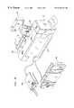
- FIG. 1 bis an isometric view of the docking station and patient monitor shown in FIG. 1 a.
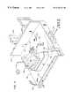
- FIG. 2is an isometric view of the docking station shown in FIG. 1 a.
- FIG. 3is a front view of apparatus suitable for use as the wall box shown in FIG. 1 a.
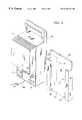
- FIG. 4is a isometric view of a second exemplary embodiment of the wallbox shown in FIG. 1 a.
- FIG. 5is a rear isometric view of the wallbox shown in FIG. 4 attached to the monitor shown in FIG. 1 .
- FIG. 1 aAn exemplary docking station system 100 including a docking station 111 in accordance with the present invention is shown in FIG. 1 a .
- a portable monitor 102acquires physiological data signals from a plurality of sensors (not shown), which may include both invasive and non-invasive devices for collecting physiological data from a patient.
- the portable monitor 102displays the physiological data, and transmits patient data signals to docking station 111 (It will be understood by one skilled in the art that the term “patient data”, as used herein, may refer to the processed information derived from the signals produced by sensors attached to the patient.
- patient datain this sense may include, for example, red, green and blue raster-scan video signals toldrive a slave display, or signals to provide status and control information to control auxiliary devices).
- the docking station 111provides power and communications services to the portable monitor 102 while monitor 102 is mounted on the docking station.
- the mounting mechanismprovides for rapid disconnection of the monitor 102 from the docking station 111 (both mechanically and electrically) for transport. Preferably, the disconnection is accomplished in a single step, so that the user can pick up monitor 102 and transport it to another location, without handling any individual cables or connectors.
- docking station 111includes two modular components.
- the first componentis the docking station platform 110 .
- Portable monitor 102may be placed on the docking station platform 110 , which may be positioned in the patient area, for example, near the patient's bed or attached to the bedframe.
- Docking station platform 110provides mechanical support for the portable monitor 102 , as well as connections to bedside display 120 , power 134 , and video display 124 .
- Docking Station 111can also communicate with local area networks (LANs) via couplings 170 , 172 and 174 . Docking station may provide communications with a computer or intelligent workstation 122 , via the networks.
- LANslocal area networks
- Docking station 111provides a simple mechanism to connect portable monitor 102 with several devices and networks without the need to connect individual cables for each device or network. Data and power connectors on the docking station platform 110 and on the case of portable monitor 102 allow simultaneous physical and electrical couplings to be established.
- the second componentis a power supply and network box 140 referred to herein as wallbox 140 .
- Wallbox 140is mounted to a wall or other stationary surface.
- Docking station 111may, include a wallbox 140 coupled to connectors 110 c and 110 d as shown in FIG. 2 .
- the wallbox 140provides power for operating monitor 102 and for charging a battery pack within (or attached to) monitor 102 .
- Wallbox 140also provides communications links to networks and devices, both inside and outside of the room in which docking station 111 is located.
- Portable monitor 102is a self-contained, standalone monitoring system. Monitor 102 includes all of the processing electronics necessary to process, display and store patient data during transport. In the exemplary embodiment described herein, portable monitor 102 does not include a broad suite of network interfaces; during transport, the exemplary monitor 102 does not have any connections to a central monitoring system or to communications networks. Portable monitor 102 has a rechargeable battery pack for use during transport. Portable monitor is also capable of receiving power from an external power supply. In the first exemplary embodiment of the invention, power is received from wallbox 140 by way of docking station platform 110 . In a second exemplary embodiment (described below with reference to FIGS. 4 and 5 ), portable monitor may receive power by either one of two different external methods: (1) via docking station platform 110 , and (2) via a Power Source and Network (PSN) box 240 that attaches directly to monitor 102 .
- PSNPower Source and Network
- the bedside display 120may be a slave unit receiving signals for display from docking station 111 .
- bedside display 120may be a conventional bedside patient monitoring unit which receives, stores, processes, displays and transmits medical data.
- the bedside displaymay be an intelligent workstation 122 with a VGA display and conventional disk storage.
- FIG. 1 bshows an isometric view of the first exemplary embodiment of the invention, including a docking station platform 110 , a wallbox 140 and monitor assembly 100 of FIG. 1 a .
- the docking station platform 110is connected to wallbox 140 by one or more cables 142 .
- Portable monitor 102is mounted on docking station platform 110 , providing physical support, power, and communications. Monitor 102 acquires physiological data signals from data acquisition pods 150 and 152 for EKG data for pressure data, respectively.
- a non-invasive blood pressure cartridge 160 and an end tidal CO 2 cartridge 162collect additional patient data.
- Cartridges 160 and 162 , a hardcopy recorder 164 and a battery pack 166are individually attached to portable monitor 102 for purposes of illustration.
- FIG. 2shows an isometric view of an exemplary docking station platform 110 to which portable monitor 102 may be attached.
- a connector 110 aprovides data communications couplings to the portable monitor.
- a guide 110 bwhich may be integral with connector 110 a as shown in FIG. 2, facilitates proper positioning of monitor 102 on docking station platform 110 , and assists in maintaining monitor 102 in position while monitor 102 is on docking station platform 110 .
- Guide 110 bprevents sideways motion between the portable monitor and the docking station.
- Optional guide pins 110 h and vertical member 110 kmay be used in addition to, or in place of, guide 110 b to assist in positioning the portable monitor 102 and preventing horizontal motion when monitor 102 is mounted on docking station platform 110 .
- a plurality of latches 110 jare shown pivotably mounted to the sides of docking station platform 110 .
- the latches 110 jmay be attached to the portable monitor 102 to prevent vertical motion so the portable monitor cannot be accidentally lifted off while mounted to the docking station. It is understood by those skilled in the art that a variety of conventional detachable fasteners may be substituted for latches 110 j.
- connector 110 a and guide 110 bmay be separate from one another. There may be multiple connectors 110 a to transmit data between portable monitor 102 and docking station 111 . Additional mechanical fasteners may be added to improve the stability of the detachable mounting.
- An optional clamp 110 emay be used to mount docking station 111 in a variety of locations, including but not limited to: on an intravenous (IV) pole (not shown), a shelf or a bed frame.
- IVintravenous
- a fixed junction box 140also referred to as a wallbox
- a wallbox 140 suitable for this purposeis shown in FIG. 3 .
- clamp 110 emay be omitted and backplate 110 f may be fastened directly to the wallbox 140 .
- Connector 110 dprovides data communications links from portable monitor 102 to external devices and networks, when monitor 102 is on docking station platform 110 .
- Connector 110 bmay be a conventional connector which interfaces directly to a local area network (LAN).
- the networkmay use one of a variety of known LAN protocols, such as carrier sense multiple access with collision detection (CSMA/CD).
- CSMA/CDcarrier sense multiple access with collision detection
- the datamay be output to a conventional patient monitoring system bedside display 120 and/or to a customized intelligent workstation 122 .
- Docking station 111electrically isolates electrical paths connected to the portable monitor 102 .
- Docking station 111provides 12 volt DC power to the portable monitor 102 via connector 110 c and 110 g , for operating the monitor when it is mounted on the docking station platform 110 .
- Portable monitor 102includes a battery charger and a nickel-cadmium battery 166 (shown in FIG. 1 a ).
- the battery chargerincludes connectors and a switch to provide charge to the battery.
- the docking station 111transmits a signal to the battery charger to activate the switch, so that the battery charger recharges battery 166 while the portable monitor 102 is mounted on the docking station.
- the portable monitor 102includes alarm processing for the parameters monitored.
- the portable monitor 102provides an alarm signal to the docking station 111 if any of these alarm conditions is present.
- the docking station 111includes a separate line within cable 110 m for receiving alarm signals, if these signals are generated by the portable monitor while it is mounted on the docking station.
- An alarm output signalis received by docking station platform 110 and transmitted via line 126 to the wallbox 140 for closing relays to activate local alarm devices, such as a light or siren.
- the docking station 111also receives from the portable monitor 102 a synchronization signal which may be used to trigger a defibrillator. This signal is output from the wallbox 140 .
- the wallbox 140couples the docking station platform 110 to communications links which may include a plurality of local area networks (LANs) or bit serial or parallel-bit data links.
- the wallbox 140includes buffer amplifiers to condition the docking station output signals for transmission over these LANs.
- the wallbox 140includes a conventional interface card (not shown) which converts the twisted pair CSMA/CD signal from line 139 (shown in FIG. 1 a ) to 10 Mbits/second signal suitable for transmission on a Thinnet LAN 174 (referred to as the Unit LAN) operating in accordance with the IEEE 802.3 Type 10-Base-2 standard.
- This Unit LAN 174connects portable monitor 102 and bedside display 120 with remote stations for transferring patient data.
- the remote stationsmay be patient monitoring systems or computers.
- This Unit LAN 174is configured to produce message delays of less than 2 seconds. It is understood by one skilled in the art that a different LAN protocol may be used for Unit LAN 174 .
- wallbox 140provides a direct video connection to a bedside display 120 using a protocol such as the Electronics Industries Association's RS-232-C Interface Standard.
- a protocolsuch as the Electronics Industries Association's RS-232-C Interface Standard.
- monitor 102drives bedside display 120 , using the RS-232-C link.
- wallbox 140may include a second conventional interface card (not shown) for interfacing a second LAN 172 (referred to as the Device LAN), which may, for example, be a 10 Mbit/sec. CSMA/CD LAN, to the wallbox 140 .
- the Device LANis used within a patient's room or operating room, or to distribute patient data via a central station.
- the Device LANprovides the main communications path to transfer patient data from the portable monitor 102 to a bedside display 120 within the same room in near real-time. This LAN is configured to maintain short delays and to allow a nominal 200 msec. response time between devices.
- Wallbox 140includes a third interface card (not shown) and a separate connection 138 which provides a coupling to an additional LAN for connecting input and output devices.
- This additional LANmay use a protocol such as High Level Datalink Control (HDLC) with device polling, for predictable response time.
- This additional LANis referred to as the Micro LAN 170 .
- the Micro LANis used to connect input and output devices to the portable monitor 102 by way of the docking station 111 .
- These devicesmay include keyboards 182 , pointing devices 184 , voice recognition 186 device, a bar code reader 188 , a label printer 190 , and a remote control 192 .
- the remote control 192may be either wired or infrared (IR). The wired remote control may be more desirable in an operating room (OR) environment, because the OR lights may distort IR control signals.
- the exemplary embodimentincludes three distinct LANs for connecting the docking station to remote stations, to local stations (i.e., those within the same room) and to I/O devices, it is understood by those skilled in the field of data communications that a variety of network configurations may be used to achieve a desired level of performance and reliability for these different types of traffic.
- the network configurationmay be tailored to protect patients by isolating a device or class of devices on a separate LAN to prevent accidental or unauthorized use. Smaller installations may implement a single local area network within a site to accommodate all of the patient monitoring traffic.
- MVP 130Eight additional multivendor ports (MVP) 130 are provided to connect serial devices to the portable monitor and remote stations on the network using a known communications interface, e.g., the RS-232 interface standard.
- Wall box 140includes a demultiplexer 143 and a D/A converter (DAC) 145 which receives digital data from the portable monitor 102 and generates a plurality of analog waveform signals from the digital data. The analog signals are sent to port 129 .
- Four analog output portsprovide waveform data for transmission to external devices (e.g., displays, recorders).
- existing analog equipmentmay be connected to the portable monitor (which provides patient data in digital form in the exemplary embodiment) in order to display data collected by the monitor.
- FIGS. 4 and 5show a second exemplary embodiment of the docking station power supply and network (PSN) box 240 .
- wallbox 140as shown in FIG. 3, is mechanically configured to be permanently mounted on a wall
- PSN box 240supports operation of monitor 102 in either one of two different configurations, shown in respective FIGS. 4 and 5.
- the PSN box 240takes over part of the functionality provided by the docking station 111 (i.e., the functionality of the wallbox 140 ). In the configuration shown in FIG. 5, the PSN box 240 completely replaces the docking station 111 ; i.e., there is no docking station platform 110 .
- FIG. 4shows a PSN box 240 in a configuration similar to that shown in FIG. 1 a .
- PSN box 240detachably mounts to the wall, bed or some other support on a bracket 260 .
- a plate 252 on the back of PSN box 240slides down into a channel 266 formed between grooves 262 and 264 of bracket 260 .
- PSN box 240includes a plurality of connectors 244 , 246 , 248 , and 250 for receiving respective cables (not shown). The cables couple the PSN box 240 to networks and to power, as described above with reference to wallbox 140 as shown in FIG. 3 .
- Connector 250receives AC power from the room.
- Connectors 244 and 246connect PSN Box 240 to the micro LAN 170 (shown in FIG. 1 a ) and the Unit LAN 174 (shown in FIG. 1 a ), respectively.
- a serial port 248provides an RS-232 link to a bedside display 120 (also shown in FIG. 1 a ).
- the PSN box 240is coupled to the portable monitor 102 via a cable 268 which connects the PSN box 240 to the docking station platform 110 .
- This cableconveys the signals on the connectors 126 through 139 shown in FIG. 1 a.
- PSN box 240 shown in FIG. 4does not have as many ports as the wallbox 140 shown in FIG. 3, it is understood by one skilled in the art that a PSN box may be configured with the same number and types of ports as wallbox 140 . Internally, PSN box may include the same configuration of network interface cards and electronics as wall box 140 . It is understood by one skilled in the art that PSN box 240 may be constructed with additional interfaces as desired, or the suite of interfaces may be reduced in scope for use in smaller installations, such as the exemplary PSN box 240 .
- PSN box 240is a functional equivalent of wallbox 140 .
- PSN box 240also includes a mounting plate 252 for easy mounting on, and removal from, mounting bracket 260 .
- bracket 260may be permanently attached to a wall or other permanent surface, using conventional fasteners driven through mounting holes 261 .
- PSN box 241also includes an enclosed chimney heat sink 242 on the box.
- FIG. 5shows the same PSN box 240 installed in a different system configuration.
- the PSN box 240is attached to the back of monitor 102 , in a “semi-permanent” manner, as defined below.
- the portable monitor 102is adapted to receive a battery 166 (as shown in FIG. 1 b ), and monitor 102 has a mounting channel (not shown), similar to channel 266 , for receiving the battery.
- PSN box 240may be attached to portable monitor 102 using the battery mounting channel of the monitor.
- docking station 111(as shown in FIG. 1 a ) consists of the PSN box 240 , without docking station platform 110 .
- PSN box 240includes a connector (not shown) on the back of plate 252 for supplying power to monitor 102 via its battery connections when PSN box 240 is attached to monitor 102 .
- the battery 166 and monitor 102are configured so that an electrical coupling between them is formed when the battery 166 is mounted on the monitor 102 .
- This same couplingmay be replicated on PSN box 240 , so that attaching the PSN box 240 to monitor 102 forms an electrical coupling without attaching any cables.
- PSN box 240is attached to monitor 102 in a “semi-permanent” manner.
- the term “semi-permanent”means that monitor 102 and PSN box 240 may remain attached indefinitely; and there is no predetermined limit on the amount of time required to detach monitor 102 from PSN box 240 . Separating monitor 102 from PSN box 240 may take anywhere from several seconds to a few minutes. This amount of time may be unacceptable in an emergency, but does not generally present a problem for routine operations.
- the semi-permanent attachment techniqueis used for a monitor 102 which is not allocated by the user as a transport monitor. The monitor 102 is used in the same fashion as a fixed location monitoring system. This semi-permanent attachment may be contrasted to the detachable mounting means on docking station platform 110 . Monitor 102 may be removed from docking station platform 110 within seconds, which is especially advantageous for transport in an emergency situation.
- the docking station platform 110When the PSN box 240 is attached directly to monitor 102 , the docking station platform 110 is not used.
- the assembly 200 consisting of the monitor 102 and the PSN box 240may be placed on a table, a stand, or other suitable surface.
- the combination 200 of the monitor 102 and PSN box 240may be considered a tethered monitor 200 , which may be moved subject to constraints due to the power cord (not shown) and data communications cables (not shown).
- PSN box 240may be connected directly to the monitor 102 .
- a coupling device 270provides circuit paths between the connectors 272 and 274 on the bottom of portable monitor 102 and the bottom of PSN box 240 , respectively.
- coupling device 270includes the same connectors 110 a and 110 g that are used on docking station platform 110 , for the interface with connector 272 . Electrically, coupling device 270 performs the same functions as cable 142 and connectors 110 a and 110 g , as shown in FIG. 2 . In addition, coupling device 270 provides structural support to prevent accidental separation of PSN box 240 from monitor 102 . The semi-permanent attachment is formed using fasteners 276 which may, for example, be screws. The additional mechanical support provided by coupling device 270 is important because the assembly 200 may be jostled around accidentally. Assembly 200 rests on a surface, and may not be firmly attached to any structure.
- PSN box 240provides advantageous flexibility. When PSN box 240 is coupled to monitor 102 as shown in FIG. 5, the resulting combination provides the same functionality as a conventional bedside display unit in a compact form; ports 244 and 246 for interfacing with communications networks 170 and 174 and a coupling 250 for receiving power are provided.
- the PSN box 240provides the network interface capability that is typically desired in a fixed location monitoring system, and is typically absent in transportable monitoring systems in the prior art. A separate docking station platform 110 is not required, which may reduce costs. This type of configuration may be desirable if the user does not intend to use the monitor 102 for patient transport under emergency conditions.
- PSN box 240essentially converts a reduced function monitoring system (i.e., a system without network interface capability) into a full function monitoring system with network interfaces.
- Portable monitor 102may now be mounted on, or removed from, docking station platform 110 in substantially less than a minute. Monitor 102 may now be used as a bedside monitor while mounted on docking station platform 110 , and as a transport monitor when removed from platform 110 .
- the userhas transformed the semi-permanent attachment into a modular system, with the capability to pick up the monitor and transport it, substantially avoiding any delays to configure the apparatus for transport.
Landscapes
- Health & Medical Sciences (AREA)
- Engineering & Computer Science (AREA)
- Biomedical Technology (AREA)
- Life Sciences & Earth Sciences (AREA)
- General Health & Medical Sciences (AREA)
- Medical Informatics (AREA)
- Public Health (AREA)
- Business, Economics & Management (AREA)
- General Business, Economics & Management (AREA)
- Epidemiology (AREA)
- Primary Health Care (AREA)
- Computer Networks & Wireless Communication (AREA)
- Physics & Mathematics (AREA)
- Biophysics (AREA)
- Pathology (AREA)
- Heart & Thoracic Surgery (AREA)
- Molecular Biology (AREA)
- Surgery (AREA)
- Animal Behavior & Ethology (AREA)
- Veterinary Medicine (AREA)
- Measuring And Recording Apparatus For Diagnosis (AREA)
Abstract
Description
This is a continuation of Ser. No. 08/252,153 filed Jun. 1, 1994 now abandoned which is a continuation of Ser. No. 07/989,410 filed Dec. 11, 1992, now abandoned.
The following U.S. applications which are assigned to the same assignee as the instant application and filed concurrently therewith have related subject matter:
U.S. Ser. No. 07/988,989, U.S. Pat. 5,375,604, entitled TRANSPORTABLE MODULAR PATIENT MONITOR; U.S. Ser. No. 07/989,414 entitled DATA ACQUISITION POD FOR A PATIENT MONITORING SYSTEM; 07/989,415 entitled TRANSPORTABLE MODULAR PATIENT MONITOR WITH DATA ACQUISITION MODULES; and U.S. Ser. No. 07/989,416 entitled PRESSURE DATA ACQUISITION DEVICE FOR A PATIENT MONITORING SYSTEM.
The present invention relates to medical systems and in particular to patient monitoring systems for collecting, storing transmitting and displaying medical data.
In hospitals and other health care environments, it is often necessary to continually collect and analyze a variety of medical data from a patient. These data may include electrocardiogram, temperature, blood pressure, respiration, pulse and other parameters.
Monitoring systems in the related art have typically fallen into one of two general categories: multi-function monitoring, recording and displaying systems which process and collect all of the data desired, but are bulky and difficult to transport; and small, portable systems which are easy to transport, but process and collect fewer types of data and have limited storage capability. Initially (e.g., in an ambulance or an emergency room) a patient is connected to a simple, portable monitor to observe a limited number of medical attributes, such as EKG or non-invasive blood pressure. As the patient moves to higher care facilities (e.g., an intensive care unit or operating room) it is desirable to augment these simple monitors to observe additional parameters. Generally, this is accomplished by disconnecting the patient from the simple monitor and connecting the patient to a monitoring system having more robust capabilities.
The need for continuity of data collection and display is most pressing in emergency situations. During an emergency, the speed at which a patient is transferred from a bed to an operating room or intensive care unit may substantially impact the patient's chance of survival. It is important to provide the same level of monitoring in transport as at the stationary bedside. It is desirable from a clinical point of view to provide a continuous monitoring capability and data history availability which follow the patient.
Two major considerations in the design of transport monitoring systems have been ease and speed of system reconfiguration. It is undesirable to disconnect the patient from a set of sensors coupled to a fixed location monitoring system and attach a new set of sensors coupled to a portable monitor immediately prior to transportation or administration of critical procedures. It is equally undesirable to disconnect each sensor from a fixed location monitoring system and reconnect the individual sensors to a portable monitoring system for transport.
U.S. Pat. Nos. 4,715,385 and 4,895,385 to Cudahy et al. discuss a monitoring system which includes a fixed location display unit and a portable display unit. A digital acquisition and processing module (DAPM) receives data from sensors attached to the patient and provides the data to either or both of the fixed and portable display units. Normally, the DAPM is inserted into a bedside display unit located near the patient's bed. When it is necessary to reconfigure the system for transporting the patient, the DAPM is connected to the portable display and then disconnected from the bedside display. The DAPM remains attached to the patient during this reconfiguration step and during patient transport, eliminating the need to reconnect the patient to intrusive devices. Once the DAPM is disconnected from the bedside display, a transportable, monitoring system is formed, comprising the portable display and DAPM.
A feature of the DAPM which may be undesirable is the need to connect cables between the DAPM and the transportable monitor to provide continuous monitoring during transport. In a life threatening situation, any time spent performing equipment configuring steps (such as connecting cables) to prepare the monitoring system for transport may impact the patient's chance for survival.
Another feature of the DAPM which may be undesirable is the need to have at least two displays (a portable monitor and a fixed display) if both portable operations and coupling to room related services are desired. The DAPM is connected to the patient to receive data. It is connected to the portable monitor during transport of the patient. In order to couple the patient data source to a power source or electronics in the patient's room or to a communications network, the DAPM must be inserted into the fixed display for coupling with any equipment fixed in the room (e.g., a hardcopy output device or an outside network. If there is no fixed display or if the fixed display is already in use, the DAPM cannot be connected to an external network. The configuration (portable display and DAPM) used while transporting the patient cannot connect directly to room related services.
Additional simplification of the steps performed to reconfigure the system is desirable, in order to reduce the time to prepare the patient and monitoring system for transport to an operating room or intensive care unit.
A docking station for a portable monitor is adapted for use in a system which includes a portable monitor and a communications network. The portable monitor displays and processes patient data signals from a plurality of sensors.
The docking station includes a detachable mounting which holds the portable monitor on the docking station. The portable monitor, when it is mounted on the docking station, provides patient data signals. The docking station transfers patient data to the communications network which is coupled to the docking station.
When the portable monitor is mounted on the docking station, the docking station provides power to the portable monitor as well as links to data from a plurality of communications networks and devices.
FIG. 1ais a block diagram of a system which includes a docking station in accordance with the invention.
FIG. 1bis an isometric view of the docking station and patient monitor shown in FIG. 1a.
FIG. 2 is an isometric view of the docking station shown in FIG. 1a.
FIG. 3 is a front view of apparatus suitable for use as the wall box shown in FIG. 1a.
FIG. 4 is a isometric view of a second exemplary embodiment of the wallbox shown in FIG. 1a.
FIG. 5 is a rear isometric view of the wallbox shown in FIG. 4 attached to the monitor shown in FIG.1.
An exemplarydocking station system 100 including adocking station 111 in accordance with the present invention is shown in FIG. 1a. Aportable monitor 102 acquires physiological data signals from a plurality of sensors (not shown), which may include both invasive and non-invasive devices for collecting physiological data from a patient. Theportable monitor 102 displays the physiological data, and transmits patient data signals to docking station111 (It will be understood by one skilled in the art that the term “patient data”, as used herein, may refer to the processed information derived from the signals produced by sensors attached to the patient. Thus “patient data” in this sense may include, for example, red, green and blue raster-scan video signals toldrive a slave display, or signals to provide status and control information to control auxiliary devices). Thedocking station 111 provides power and communications services to theportable monitor 102 whilemonitor 102 is mounted on the docking station. The mounting mechanism provides for rapid disconnection of themonitor 102 from the docking station111 (both mechanically and electrically) for transport. Preferably, the disconnection is accomplished in a single step, so that the user can pick upmonitor 102 and transport it to another location, without handling any individual cables or connectors.
In the first exemplary embodiment,docking station 111 includes two modular components. The first component is thedocking station platform 110.Portable monitor 102 may be placed on thedocking station platform 110, which may be positioned in the patient area, for example, near the patient's bed or attached to the bedframe.Docking station platform 110 provides mechanical support for theportable monitor 102, as well as connections tobedside display 120,power 134, andvideo display 124.Docking Station 111 can also communicate with local area networks (LANs) viacouplings intelligent workstation 122, via the networks.Docking station 111 provides a simple mechanism to connectportable monitor 102 with several devices and networks without the need to connect individual cables for each device or network. Data and power connectors on thedocking station platform 110 and on the case ofportable monitor 102 allow simultaneous physical and electrical couplings to be established.
The second component is a power supply andnetwork box 140 referred to herein aswallbox 140.Wallbox 140 is mounted to a wall or other stationary surface.Docking station 111 may, include awallbox 140 coupled to connectors110cand110das shown in FIG.2. Thewallbox 140 provides power for operatingmonitor 102 and for charging a battery pack within (or attached to) monitor102.Wallbox 140 also provides communications links to networks and devices, both inside and outside of the room in whichdocking station 111 is located.
Thebedside display 120 may be a slave unit receiving signals for display fromdocking station 111. Alternately,bedside display 120 may be a conventional bedside patient monitoring unit which receives, stores, processes, displays and transmits medical data. Alternately, the bedside display may be anintelligent workstation 122 with a VGA display and conventional disk storage.
FIG. 1bshows an isometric view of the first exemplary embodiment of the invention, including adocking station platform 110, awallbox 140 and monitorassembly 100 of FIG. 1a. Thedocking station platform 110 is connected to wallbox140 by one ormore cables 142.Portable monitor 102 is mounted ondocking station platform 110, providing physical support, power, and communications.Monitor 102 acquires physiological data signals fromdata acquisition pods blood pressure cartridge 160 and an end tidal CO2cartridge162 collect additional patient data.Cartridges hardcopy recorder 164 and abattery pack 166 are individually attached toportable monitor 102 for purposes of illustration.
FIG. 2 shows an isometric view of an exemplarydocking station platform 110 to whichportable monitor 102 may be attached. A connector110aprovides data communications couplings to the portable monitor. A guide110b, which may be integral with connector110aas shown in FIG. 2, facilitates proper positioning ofmonitor 102 ondocking station platform 110, and assists in maintainingmonitor 102 in position whilemonitor 102 is ondocking station platform 110. Guide110bprevents sideways motion between the portable monitor and the docking station. Optional guide pins110hand vertical member110kmay be used in addition to, or in place of, guide110bto assist in positioning theportable monitor 102 and preventing horizontal motion whenmonitor 102 is mounted ondocking station platform 110.
A plurality of latches110jare shown pivotably mounted to the sides ofdocking station platform 110. The latches110jmay be attached to theportable monitor 102 to prevent vertical motion so the portable monitor cannot be accidentally lifted off while mounted to the docking station. It is understood by those skilled in the art that a variety of conventional detachable fasteners may be substituted for latches110j.
Many variations of the docking station mechanical configuration are possible. For example, connector110aand guide110bmay be separate from one another. There may be multiple connectors110ato transmit data betweenportable monitor 102 anddocking station 111. Additional mechanical fasteners may be added to improve the stability of the detachable mounting.
An optional clamp110emay be used to mountdocking station 111 in a variety of locations, including but not limited to: on an intravenous (IV) pole (not shown), a shelf or a bed frame. When mounting thedocking station platform 110 to a bed or IV pole, both of which are movable, it is desirable to provide a fixed junction box140 (also referred to as a wallbox) for coupling the docking station with power, devices and networks outside of the room in which the docking station is located. Awallbox 140 suitable for this purpose is shown in FIG.3. Alternatively, clamp110emay be omitted and backplate110fmay be fastened directly to thewallbox 140.
Referring to FIG. 2, a separate connector llog provides power to theportable monitor 102. Connector110dprovides data communications links fromportable monitor 102 to external devices and networks, whenmonitor 102 is ondocking station platform 110. Connector110bmay be a conventional connector which interfaces directly to a local area network (LAN). The network may use one of a variety of known LAN protocols, such as carrier sense multiple access with collision detection (CSMA/CD). Additionally, the data may be output to a conventional patient monitoringsystem bedside display 120 and/or to a customizedintelligent workstation 122.Docking station 111 electrically isolates electrical paths connected to theportable monitor 102.
Theportable monitor 102 includes alarm processing for the parameters monitored. Theportable monitor 102 provides an alarm signal to thedocking station 111 if any of these alarm conditions is present. Thedocking station 111 includes a separate line within cable110mfor receiving alarm signals, if these signals are generated by the portable monitor while it is mounted on the docking station. An alarm output signal is received bydocking station platform 110 and transmitted vialine 126 to thewallbox 140 for closing relays to activate local alarm devices, such as a light or siren.
Thedocking station 111 also receives from the portable monitor102 a synchronization signal which may be used to trigger a defibrillator. This signal is output from thewallbox 140.
Referring to FIG. 3, thewallbox 140 couples thedocking station platform 110 to communications links which may include a plurality of local area networks (LANs) or bit serial or parallel-bit data links. Thewallbox 140 includes buffer amplifiers to condition the docking station output signals for transmission over these LANs. In the exemplary embodiment, thewallbox 140 includes a conventional interface card (not shown) which converts the twisted pair CSMA/CD signal from line139 (shown in FIG. 1a) to 10 Mbits/second signal suitable for transmission on a Thinnet LAN174 (referred to as the Unit LAN) operating in accordance with the IEEE 802.3 Type 10-Base-2 standard. ThisUnit LAN 174 connectsportable monitor 102 andbedside display 120 with remote stations for transferring patient data. The remote stations may be patient monitoring systems or computers. ThisUnit LAN 174 is configured to produce message delays of less than 2 seconds. It is understood by one skilled in the art that a different LAN protocol may be used forUnit LAN 174.
In the exemplary embodiment,wallbox 140 provides a direct video connection to abedside display 120 using a protocol such as the Electronics Industries Association's RS-232-C Interface Standard. When theportable monitor 102 is on thedocking station platform 110, monitor102drives bedside display 120, using the RS-232-C link. Alternatively, wallbox140 may include a second conventional interface card (not shown) for interfacing a second LAN172 (referred to as the Device LAN), which may, for example, be a 10 Mbit/sec. CSMA/CD LAN, to thewallbox 140. The Device LAN is used within a patient's room or operating room, or to distribute patient data via a central station. The Device LAN provides the main communications path to transfer patient data from theportable monitor 102 to abedside display 120 within the same room in near real-time. This LAN is configured to maintain short delays and to allow a nominal 200 msec. response time between devices.
Although the exemplary embodiment, as shown in FIG. 3, includes three distinct LANs for connecting the docking station to remote stations, to local stations (i.e., those within the same room) and to I/O devices, it is understood by those skilled in the field of data communications that a variety of network configurations may be used to achieve a desired level of performance and reliability for these different types of traffic. In addition, the network configuration may be tailored to protect patients by isolating a device or class of devices on a separate LAN to prevent accidental or unauthorized use. Smaller installations may implement a single local area network within a site to accommodate all of the patient monitoring traffic.
Eight additional multivendor ports (MVP)130 are provided to connect serial devices to the portable monitor and remote stations on the network using a known communications interface, e.g., the RS-232 interface standard.
FIGS. 4 and 5 show a second exemplary embodiment of the docking station power supply and network (PSN)box 240. Whereaswallbox 140, as shown in FIG. 3, is mechanically configured to be permanently mounted on a wall,PSN box 240 supports operation ofmonitor 102 in either one of two different configurations, shown in respective FIGS. 4 and 5.
In the configuration shown in FIG. 4, thePSN box 240 takes over part of the functionality provided by the docking station111 (i.e., the functionality of the wallbox140). In the configuration shown in FIG. 5, thePSN box 240 completely replaces thedocking station 111; i.e., there is nodocking station platform 110.
FIG. 4 shows aPSN box 240 in a configuration similar to that shown in FIG. 1a.PSN box 240 detachably mounts to the wall, bed or some other support on abracket 260. In the exemplary embodiment, aplate 252 on the back ofPSN box 240 slides down into achannel 266 formed betweengrooves 262 and264 ofbracket 260.PSN box 240 includes a plurality ofconnectors PSN box 240 to networks and to power, as described above with reference towallbox 140 as shown in FIG.3.Connector 250 receives AC power from the room.Connectors PSN Box 240 to the micro LAN170 (shown in FIG. 1a) and the Unit LAN174 (shown in FIG. 1a), respectively. Aserial port 248 provides an RS-232 link to a bedside display120 (also shown in FIG. 1a).
In this configuration, thePSN box 240 is coupled to theportable monitor 102 via acable 268 which connects thePSN box 240 to thedocking station platform 110. This cable conveys the signals on theconnectors 126 through139 shown in FIG. 1a.
Although theexemplary PSN box 240 shown in FIG. 4 does not have as many ports as thewallbox 140 shown in FIG. 3, it is understood by one skilled in the art that a PSN box may be configured with the same number and types of ports aswallbox 140. Internally, PSN box may include the same configuration of network interface cards and electronics aswall box 140. It is understood by one skilled in the art thatPSN box 240 may be constructed with additional interfaces as desired, or the suite of interfaces may be reduced in scope for use in smaller installations, such as theexemplary PSN box 240.
The primary difference betweenwallbox 140 andPSN box 240 is the mechanical packaging. Additional port(s)274 (shown in FIG. 5) are provided on the bottom ofPSN box 240. One ormore cables 268 are attached to port(s)274 to couplePSN box 240 todocking station platform 110, as shown in FIG.2. In the configuration shown in FIG. 4,PSN box 240 is a functional equivalent ofwallbox 140.PSN box 240 also includes a mountingplate 252 for easy mounting on, and removal from, mountingbracket 260. As shown in FIG. 4,bracket 260 may be permanently attached to a wall or other permanent surface, using conventional fasteners driven through mountingholes 261. PSN box241 also includes an enclosedchimney heat sink 242 on the box.
FIG. 5 shows thesame PSN box 240 installed in a different system configuration. Instead of mountingPSN box 240 on the wall, thePSN box 240 is attached to the back ofmonitor 102, in a “semi-permanent” manner, as defined below. Preferably, theportable monitor 102 is adapted to receive a battery166 (as shown in FIG. 1b), and monitor102 has a mounting channel (not shown), similar tochannel 266, for receiving the battery. Once thebattery 166 is removed fromportable monitor 102,PSN box 240 may be attached toportable monitor 102 using the battery mounting channel of the monitor. In this configuration, docking station111 (as shown in FIG. 1a) consists of thePSN box 240, withoutdocking station platform 110.
In an alternative embodiment of the PSN box (not shown),PSN box 240 includes a connector (not shown) on the back ofplate 252 for supplying power to monitor102 via its battery connections whenPSN box 240 is attached to monitor102. Preferably thebattery 166 and monitor102 (shown in FIG. 1b) are configured so that an electrical coupling between them is formed when thebattery 166 is mounted on themonitor 102. This same coupling may be replicated onPSN box 240, so that attaching thePSN box 240 to monitor102 forms an electrical coupling without attaching any cables.
As shown in FIG. 5,PSN box 240 is attached to monitor102 in a “semi-permanent” manner. As defined herein, the term “semi-permanent” means that monitor102 andPSN box 240 may remain attached indefinitely; and there is no predetermined limit on the amount of time required to detach monitor102 fromPSN box 240. Separatingmonitor 102 fromPSN box 240 may take anywhere from several seconds to a few minutes. This amount of time may be unacceptable in an emergency, but does not generally present a problem for routine operations. Preferably, the semi-permanent attachment technique is used for amonitor 102 which is not allocated by the user as a transport monitor. Themonitor 102 is used in the same fashion as a fixed location monitoring system. This semi-permanent attachment may be contrasted to the detachable mounting means ondocking station platform 110.Monitor 102 may be removed fromdocking station platform 110 within seconds, which is especially advantageous for transport in an emergency situation.
When thePSN box 240 is attached directly to monitor102, thedocking station platform 110 is not used. Theassembly 200 consisting of themonitor 102 and thePSN box 240 may be placed on a table, a stand, or other suitable surface. In this configuration, thecombination 200 of themonitor 102 andPSN box 240 may be considered atethered monitor 200, which may be moved subject to constraints due to the power cord (not shown) and data communications cables (not shown). Instead of connecting themonitor 102 to theplatform 110 and connectingplatform 110 to wallbox140 by a cable268 (as shown in FIG.4),PSN box 240 may be connected directly to themonitor 102. Acoupling device 270 provides circuit paths between theconnectors portable monitor 102 and the bottom ofPSN box 240, respectively.
Preferably,coupling device 270 includes the same connectors110aand110gthat are used ondocking station platform 110, for the interface withconnector 272. Electrically,coupling device 270 performs the same functions ascable 142 and connectors110aand110g, as shown in FIG.2. In addition,coupling device 270 provides structural support to prevent accidental separation ofPSN box 240 frommonitor 102. The semi-permanent attachment is formed usingfasteners 276 which may, for example, be screws. The additional mechanical support provided bycoupling device 270 is important because theassembly 200 may be jostled around accidentally.Assembly 200 rests on a surface, and may not be firmly attached to any structure.
The use ofPSN box 240 as shown in FIG. 5 provides advantageous flexibility. WhenPSN box 240 is coupled to monitor102 as shown in FIG. 5, the resulting combination provides the same functionality as a conventional bedside display unit in a compact form;ports communications networks coupling 250 for receiving power are provided. ThePSN box 240 provides the network interface capability that is typically desired in a fixed location monitoring system, and is typically absent in transportable monitoring systems in the prior art. A separatedocking station platform 110 is not required, which may reduce costs. This type of configuration may be desirable if the user does not intend to use themonitor 102 for patient transport under emergency conditions.PSN box 240 essentially converts a reduced function monitoring system (i.e., a system without network interface capability) into a full function monitoring system with network interfaces.
As user needs change, it may be desirable to reallocate this relatively fixed monitor for use as a transportable monitor.Connector 270 is easily removed in a few minutes.Portable monitor 102 may now be mounted on, or removed from,docking station platform 110 in substantially less than a minute.Monitor 102 may now be used as a bedside monitor while mounted ondocking station platform 110, and as a transport monitor when removed fromplatform 110. By adding thedocking station platform 110 andcable 268, the user has transformed the semi-permanent attachment into a modular system, with the capability to pick up the monitor and transport it, substantially avoiding any delays to configure the apparatus for transport.
It is understood by one skilled in the art that many variations of the embodiments described herein are contemplated. While the invention has been described in terms of exemplary embodiments, it is contemplated that it may be practiced as outlined above with modifications within the spirit and scope of the appended claims.
Claims (34)
1. Docking station apparatus adapted for use in a continuous patient monitoring system wherein the patient may be located within a first patient monitoring area, or transported out of said first patient monitoring area and into a second patient monitoring area remote from said first patient monitoring area, said system including a portable monitor adapted for being battery powered and coupled to a plurality of sensors, said monitor including means for continuously receiving, processing and displaying in real-time, patient physiological data signals provided by the sensors irrespective of said patient being located within said first or said second patient monitoring areas or being transported therebetween, and a communications network having an interface connection which is located in a relatively fixed position within said first and said second patient monitoring areas, the docking station apparatus including first and second docking station platforms, one in each of said first and second patient monitoring areas, respectively, each docking station platform comprising:
(a) mounting means for detachably coupling the portable monitor to the docking station platform so as to provide physical support for said portable monitor when it is mounted on said docking station platform;
(b) means for continuously receiving from the portable monitor in real-time patient physiological data received by the portable monitor when the portable monitor is coupled to the docking station platform; and
(c) means for continuously transferring the received patient physiological data to the interface connection of the communications network when the portable monitor is coupled to the docking station platform,
wherein said portable monitor continuously receives, processes and displays said patient physiological data while said portable monitor is being connected to and disconnected from the docking station platform, said connecting and disconnecting being accomplished without handling any individual cables or connectors.
2. A docking station platform in accordance with claim1, further comprising means for transferring the patient data to a computer workstation by way of the communications network when the portable monitor is coupled to the docking station platform.
3. A docking station platform in accordance with claim1, further comprising means for providing power from the docking station to the portable monitor when the portable monitor is coupled to the docking station platform.
4. A docking station platform in accordance with claim2, in which the mounting means include:
at least one latch which secures the portable monitor to the docking station platform, preventing vertical motion between the docking station platform and the portable monitor while the portable monitor is coupled to the docking station platform; and
at least one vertical pin which prevents horizontal motion between the portable monitor and the docking station platform while the portable monitor is coupled to the docking station platform.
5. A docking station platform in accordance with claim2, in which the mounting means include:
at least one latch which prevents the portable monitor from being lifted off of the docking station platform while the portable monitor is coupled to the docking station platform; and
a vertically mounted electrical connector which prevents sideways motion between the portable monitor and the docking station platform while the portable monitor is coupled to the docking station platform.
6. A docking station platform in accordance with claim1, further comprising:
a plurality of serial ports which receive input signals from a respective plurality of input devices;
means for coupling the serial ports to the portable monitor when the portable monitor is coupled to the docking station platform and for transmitting the input signals to the portable monitor.
7. A docking station platform in accordance with claim1, wherein the portable monitor has a battery and a battery charger, and the docking station platform includes means for causing the battery charger to charge the battery when the portable monitor is coupled to the docking station platform.
8. A docking station platform in accordance with claim7, wherein the portable monitor has means for detachably mounting the battery to the portable monitor, and said docking station platform includes:
a power supply and network (PSN) box, comprising:
means for electrically coupling the PSN box to the portable monitor, and
means for attaching the PSN box to the battery mounting means of the portable monitor when the battery is not mounted on the battery mounting means.
9. A docking station platform in accordance with claim1, further comprising:
means for receiving an alarm signal from the portable monitor when the portable monitor is coupled to the docking station platform; and
means responsive to the alarm signal receiving means for transmitting an alarm activation signal to an alarm device.
10. A docking station platform in accordance with claim1 in which a plurality of input devices are coupled to the communications network, the docking station platform further comprising means for transferring input signals from the communications network to the portable monitor when the portable monitor is coupled to the docking station platform.
11. A docking station platform in accordance with claim10, wherein the plurality of input devices includes a voice recognition device.
12. A docking station platform in accordance with claim10, wherein the plurality of input devices includes a bar code reader.
13. A docking station platform in accordance with claim10, wherein the plurality of input devices includes a remote control device which controls operation of the portable monitor.
14. A docking station platform in accordance with claim10, wherein the plurality of input devices includes a keyboard.
15. A docking station platform in accordance with claim1 in which a plurality of output devices are coupled to the communications network, the docking station platform further comprising means for transferring output signals from the portable monitor to the communications network when the portable monitor is coupled to the docking station platform.
16. A docking station platform in accordance with claim15, wherein the plurality of output devices includes a label printer.
17. A docking station platform in accordance with claim1, further comprising:
a demultiplexer which separates the patient data received from the portable monitor into a plurality of output signals;
means for converting the plurality of output signals into a plurality of analog signals; and
means for transmitting the plurality of analog signals to a plurality of analog output devices.
18. A docking station platform in accordance with claim1, further comprising means for generating and transmitting a synchronization signal to a defibrillator.
19. A docking station platform in accordance with claim1, further comprising means for attaching the docking station to an intravenous pole.
20. A docking station platform in accordance with claim1, further comprising means for attaching the docking station to the patient's bed.
21. A docking station platform in accordance with claim1, further comprising means for transferring the patient data between the portable monitor and a plurality of remote stations by way of the communications network when the portable monitor is coupled to the docking station platform.
22. A docking station platform in accordance with claim1, further including:
a power supply and network (PSN) box, comprising:
(1) attaching means for attaching the portable monitor to the PSN box,
(2) means for receiving patient data at the PSN box from the portable monitor directly when the portable monitor is attached to the PSN box, and means for receiving patient data at the PSN box from the portable monitor by way of the docking station platform platform when the portable monitor is mounted on the docking station platform, and
(3) means for transferring the received patient data to the communications network.
23. A docking station platform in accordance with claim22, further comprising:
means for providing power from the PSN box to the portable monitor by way of the docking station platform when the portable monitor is mounted on the docking station platform platform; and
means for providing power from the PSN box to the portable monitor directly when the portable monitor is attached to the PSN box.
24. A docking station platform in accordance with claim22, wherein the attaching means include means for electrically coupling the portable monitor and the PSN box.
25. A docking station platform in accordance with claim22, wherein the portable monitor has a battery and means for mounting the battery on the portable monitor, and
wherein the attaching means of the PSN box include means for attaching the PSN box to the battery mounting means of the portable monitor when the battery is not mounted on the battery mounting means.
26. A system for acquiring a continuous history of medical data from a plurality of sensors attached to a patient, adapted for use in at least first and second patient monitoring areas and during transport therebetween, each of said areas including at a relatively fixed location an interface for a patient data communications network, the system comprising:
a portable monitor adapted for being battery powered and coupled to the plurality of sensors, said monitor including means for continuously receiving, processing and displaying in real-time, patient physiological data signals provided from the plurality of sensors; and
a docking station located at said relatively fixed location in said first and second patient monitoring areas, each docking station comprising:
first coupling means for detachably coupling the portable monitor with the docking station so as to provide an electrical connection between said portable monitor and said docking station without handling any individual cables or connectors,
second coupling means for coupling the docking station to a power source and to the communications network, and
transferring means for transferring in real-time patient physiological data received in real-time by said portable monitor from the portable monitor to the communications network, and power from said power source to said portable monitor, via said first and second coupling means, when said portable monitor is coupled with said docking stations,
wherein said portable monitor continuously receives, processes and displays said patient physiological data signals while said portable monitor is being connected to and disconnected from the docking station.
27. A docking station platform in accordance with claim23, further comprising means for transferring power from the docking station to the portable monitor when the portable monitor is coupled with the docking station.
28. A docking station in accordance with claim26, in which the first coupling means includes:
at least one latch which secures the portable monitor to the docking station, preventing vertical motion between the docking station and the portable monitor while the portable monitor is coupled with the docking station; and
at least one vertical pin which prevents horizontal motion between the portable monitor and the docking station while the portable monitor is coupled to the docking station.
29. A docking station in accordance with claim28, in which the first coupling means includes:
at least one latch which prevents the portable monitor from being lifted off of the docking station while the portable monitor is coupled with the docking station; and
a vertically mounted electrical connector which prevents sideways motion between the portable monitor and the docking station while the portable monitor is coupled with the docking station.
30. A docking station in accordance with claim26, wherein said communication network comprises a plurality of serial ports which receive input signals from a respective plurality of input devices; and
said transferring means comprises means for coupling the serial ports to the portable monitor when the portable monitor is coupled to the docking station for transmitting the input signals to the portable monitor.
31. A docking station in accordance with claim26, wherein the portable monitor includes a battery and a battery charger, and the docking station includes means for transferring power from said power source to said portable monitor for causing the battery charger to charge the battery when the portable monitor is coupled to the docking station.
32. A docking station in accordance with claim31, wherein the portable monitor has means for detachably mounting the battery to the portable monitor, and said docking station includes:
a power supply and network (PSN) box, comprising:
means for electrically coupling the PSN box to the portable monitor, and
means for attaching the PSN box to the battery mounting means of the portable monitor when the battery is not mounted on the battery mounting means.
33. A docking station in accordance with claim26, wherein a plurality of output devices are coupled to the communications network, and the transferring means further comprises means for transferring output signals from the portable monitor to said output devices via the communications network when the portable monitor is coupled to the docking station.
34. A docking station in accordance with claim23, wherein said portable monitor stores patient data when it is not coupled to said docking station, and when coupled to said docking station, transfers said stored patient data to said communication network via said first and second coupling means.
Priority Applications (3)
| Application Number | Priority Date | Filing Date | Title |
|---|---|---|---|
| US08/401,332US6183417B1 (en) | 1992-12-11 | 1995-03-09 | Docking station for a patient monitoring system |
| US08/414,887US5640953A (en) | 1995-03-09 | 1995-03-31 | Portable patient monitor reconfiguration system |
| US08/414,888US5685314A (en) | 1992-12-11 | 1995-03-31 | Auxiliary docking station for a patient monitoring system |
Applications Claiming Priority (3)
| Application Number | Priority Date | Filing Date | Title |
|---|---|---|---|
| US98941092A | 1992-12-11 | 1992-12-11 | |
| US25215394A | 1994-06-01 | 1994-06-01 | |
| US08/401,332US6183417B1 (en) | 1992-12-11 | 1995-03-09 | Docking station for a patient monitoring system |
Related Parent Applications (1)
| Application Number | Title | Priority Date | Filing Date |
|---|---|---|---|
| US25215394AContinuation | 1992-12-11 | 1994-06-01 |
Related Child Applications (2)
| Application Number | Title | Priority Date | Filing Date |
|---|---|---|---|
| US08/414,887Continuation-In-PartUS5640953A (en) | 1995-03-09 | 1995-03-31 | Portable patient monitor reconfiguration system |
| US08/414,888Continuation-In-PartUS5685314A (en) | 1992-12-11 | 1995-03-31 | Auxiliary docking station for a patient monitoring system |
Publications (1)
| Publication Number | Publication Date |
|---|---|
| US6183417B1true US6183417B1 (en) | 2001-02-06 |
Family
ID=25535089
Family Applications (1)
| Application Number | Title | Priority Date | Filing Date |
|---|---|---|---|
| US08/401,332Expired - LifetimeUS6183417B1 (en) | 1992-12-11 | 1995-03-09 | Docking station for a patient monitoring system |
Country Status (7)
| Country | Link |
|---|---|
| US (1) | US6183417B1 (en) |
| EP (1) | EP0673530B1 (en) |
| JP (1) | JP3466612B2 (en) |
| AT (1) | ATE166734T1 (en) |
| DE (1) | DE69318850T2 (en) |
| DK (1) | DK0673530T3 (en) |
| WO (1) | WO1994014128A2 (en) |
Cited By (150)
| Publication number | Priority date | Publication date | Assignee | Title |
|---|---|---|---|---|
| US20020084698A1 (en)* | 2000-11-20 | 2002-07-04 | Kelly Clifford Mark | Electrically isolated power and signal coupler system for a patient connected device |
| US6442432B2 (en) | 1999-12-21 | 2002-08-27 | Medtronic, Inc. | Instrumentation and software for remote monitoring and programming of implantable medical devices (IMDs) |
| US6524240B1 (en)* | 2000-11-22 | 2003-02-25 | Medwave, Inc. | Docking station for portable medical devices |
| USD470849S1 (en) | 2002-01-04 | 2003-02-25 | Medtronic Physio-Control Corp. | Docking station |
| US20030052787A1 (en)* | 2001-08-03 | 2003-03-20 | Zerhusen Robert Mark | Patient point-of-care computer system |
| US6593528B2 (en)* | 1999-11-19 | 2003-07-15 | Alaris Medical Systems, Inc. | Medical device interface system |
| US6594146B2 (en) | 2000-12-26 | 2003-07-15 | Ge Medical Systems Information Technologies, Inc. | Docking station for patient monitor or other electronic device |
| US20040104905A1 (en)* | 2002-12-02 | 2004-06-03 | Tatung Co., Ltd. | Apparatus capable of controlling brightness switching between a protable device and a docking station |
| USD492248S1 (en) | 2003-08-22 | 2004-06-29 | Gmp Wireless Medicine, Inc. | Battery pack for wireless ECG monitoring system |
| US20040150963A1 (en)* | 2003-01-31 | 2004-08-05 | Sonosite, Inc. | System for use with a modular apparatus for diagnostic ultrasound |
| US20040152982A1 (en)* | 2002-03-29 | 2004-08-05 | Sonosite, Inc. | Modular apparatus for diagnostic ultrasound |
| US6773397B2 (en) | 2001-10-11 | 2004-08-10 | Draeger Medical Systems, Inc. | System for processing signal data representing physiological parameters |
| US20040186357A1 (en)* | 2002-08-20 | 2004-09-23 | Welch Allyn, Inc. | Diagnostic instrument workstation |
| US6865418B2 (en) | 2002-03-04 | 2005-03-08 | Medtronic Physio-Control Corp. | Docking station for defibrillator |
| US20050133027A1 (en)* | 2003-11-12 | 2005-06-23 | Joseph Elaz | Modular medical care system |
| US20050143632A1 (en)* | 2003-11-13 | 2005-06-30 | Joseph Elaz | Processing device and display system |
| WO2005058413A3 (en)* | 2003-12-17 | 2005-10-20 | Medtronic Physio Control Corp | Defibrillator patient monitoring pod |
| US20050267402A1 (en)* | 2004-05-27 | 2005-12-01 | Janice Stewart | Multi-state alarm system for a medical pump |
| US20050277890A1 (en)* | 2004-05-27 | 2005-12-15 | Janice Stewart | Medical device configuration based on recognition of identification information |
| US20050277873A1 (en)* | 2004-05-27 | 2005-12-15 | Janice Stewart | Identification information recognition system for a medical device |
| US20050288571A1 (en)* | 2002-08-20 | 2005-12-29 | Welch Allyn, Inc. | Mobile medical workstation |
| US20060094935A1 (en)* | 2004-10-20 | 2006-05-04 | Coulbourn Instruments, L.L.C. | Portable psychophysiology system and method of use |
| US20060097869A1 (en)* | 2004-11-10 | 2006-05-11 | Concari Gabriel E | Portable alarm system |
| US20060098666A1 (en)* | 2004-10-25 | 2006-05-11 | Francis Conde Powell Justin M | Portable device configuration system |
| US20060142808A1 (en)* | 2003-04-22 | 2006-06-29 | Christopher Pearce | Defibrillator/monitor system having a pod with leads capable of wirelessly communicating |
| WO2006073852A1 (en)* | 2004-12-30 | 2006-07-13 | Medtronic Emergency Response Systems, Inc. | Medical device information system |
| USRE39233E1 (en) | 1994-04-25 | 2006-08-08 | Mcgrath John E | Consolidated monitoring cable arrangement |
| US7140546B1 (en)* | 2002-12-12 | 2006-11-28 | Symbol Technologies, Inc. | Battery pack with integrated human interface devices |
| US20070016443A1 (en)* | 2005-07-13 | 2007-01-18 | Vitality, Inc. | Medication compliance systems, methods and devices with configurable and adaptable escalation engine |
| US20070210917A1 (en)* | 2004-08-02 | 2007-09-13 | Collins Williams F Jr | Wireless bed connectivity |
| US20070276272A1 (en)* | 2006-05-15 | 2007-11-29 | Schneidewend Daniel R | Invasive cardiology digital signal amplifier and acquisition device |
| US7319386B2 (en) | 2004-08-02 | 2008-01-15 | Hill-Rom Services, Inc. | Configurable system for alerting caregivers |
| US20080077185A1 (en)* | 2003-12-17 | 2008-03-27 | Christopher Pearce | Defibrillator/Monitor System Having a Pod with Leads Capable of Wirelessly Communicating |
| USD566282S1 (en)* | 2005-02-18 | 2008-04-08 | Masimo Corporation | Stand for a portable patient monitor |
| US20080108884A1 (en)* | 2006-09-22 | 2008-05-08 | Kiani Massi E | Modular patient monitor |
| US20080157714A1 (en)* | 2006-12-28 | 2008-07-03 | Lemay Charles | Electronic Device Identification System |
| US20080221397A1 (en)* | 2003-12-17 | 2008-09-11 | Mcmahon Michael D | Defibrillator Patient Monitoring Pod |
| US20080224861A1 (en)* | 2003-08-21 | 2008-09-18 | Mcneely Craig A | Hospital bed having wireless data capability |
| US20080234555A1 (en)* | 2007-03-23 | 2008-09-25 | Stryker Corporation | Patient care system |
| US20080281168A1 (en)* | 2005-01-13 | 2008-11-13 | Welch Allyn, Inc. | Vital Signs Monitor |
| US20090005651A1 (en)* | 2007-06-27 | 2009-01-01 | Welch Allyn, Inc. | Portable systems, devices and methods for displaying varied information depending on usage circumstances |
| US20090056027A1 (en)* | 2007-08-29 | 2009-03-05 | Hill-Rom Services, Inc. | Mattress for a hospital bed for use in a healthcare facility and management of same |
| US20090124868A1 (en)* | 2007-11-09 | 2009-05-14 | Peter Andrew Barnett | Lightweight portable trauma treatment and patient monitoring device |
| US20090134181A1 (en)* | 2005-07-13 | 2009-05-28 | Vitality, Inc. | Medication dispenser with automatic refill |
| US20090212848A1 (en)* | 2008-02-25 | 2009-08-27 | Gary Coonan | Power supply unit for mobile workstation and method |
| US20090212744A1 (en)* | 2008-02-25 | 2009-08-27 | Werthman Dean A | System for use in gathering or processing data in a healthcare facility having fleet of mobile workstations |
| US20090217080A1 (en)* | 2008-02-22 | 2009-08-27 | Ferguson David C | Distributed fault tolerant architecture for a healthcare communication system |
| US20090212738A1 (en)* | 2008-02-25 | 2009-08-27 | Gary Coonan | Battery charging system and method of reducing variation in battery charging cycle count |
| US20090262266A1 (en)* | 2008-02-25 | 2009-10-22 | Lee Melvin Harbin | Power system petrofit kit for mobile workstation and retrofit method |
| US20090261656A1 (en)* | 2008-02-25 | 2009-10-22 | Gary Coonan | Power system for mobile workstation and method |
| US20090268385A1 (en)* | 2008-02-25 | 2009-10-29 | Lee Melvin Harbin | Mobile workstation having power system with removable battery configured for drop-in engagement therewith |
| US20090270727A1 (en)* | 2008-04-29 | 2009-10-29 | Zhensong Zhao | Docking station and ultrasonic diagnostic system |
| US20090270689A1 (en)* | 2006-06-02 | 2009-10-29 | Cbb International Pty Ltd | Monitoring system |
| US20090276104A1 (en)* | 2008-02-25 | 2009-11-05 | Gary Coonan | Mobile workstation control system configured for power system and peripheral device control |
| US20090276637A1 (en)* | 2008-02-25 | 2009-11-05 | Gary Coonan | Power control system for mobile workstation and method |
| US20100010320A1 (en)* | 2008-07-07 | 2010-01-14 | Perkins David G | Mobile medical workstation and a temporarily associating mobile computing device |
| US20100016737A1 (en)* | 2008-07-18 | 2010-01-21 | Welch Allyn, Inc. | Electro pneumatic interface for blood pressure system |
| US20100023076A1 (en)* | 2006-02-06 | 2010-01-28 | Medtronic Emergency Response Systems, Inc. | Post-download patient data protection in a medical device |
| US20100270257A1 (en)* | 2005-07-13 | 2010-10-28 | Vitality, Inc. | Medicine Bottle Cap With Electronic Embedded Curved Display |
| US20100328099A1 (en)* | 2005-07-13 | 2010-12-30 | Vitality, Inc. | Night Light With Embedded Cellular Modem |
| US7868740B2 (en) | 2007-08-29 | 2011-01-11 | Hill-Rom Services, Inc. | Association of support surfaces and beds |
| WO2011023492A1 (en)* | 2009-08-28 | 2011-03-03 | Hyb D.O.O. | Measured data converter for a patient monitoring system |
| US20110066061A1 (en)* | 2008-04-29 | 2011-03-17 | Oridion Medical 1987 Ltd. | Wireless capnography |
| US20110205062A1 (en)* | 2010-02-19 | 2011-08-25 | Pesot Whitney W | Nurse call system with additional status board |
| EP2463874A1 (en)* | 2010-12-13 | 2012-06-13 | Coactive Technologies, LLC | Control console for a medical apparatus, the console being mountable on a rail |
| US8234128B2 (en) | 2002-04-30 | 2012-07-31 | Baxter International, Inc. | System and method for verifying medical device operational parameters |
| US20130289536A1 (en)* | 2012-04-26 | 2013-10-31 | Paul Hartmann Ag | Fastener for a negative pressure therapy device |
| US20130322002A1 (en)* | 1998-09-18 | 2013-12-05 | Intermetro Industries Corporation | Mobile Computer Workstation |
| US8618918B2 (en) | 2010-04-09 | 2013-12-31 | Hill-Rom Services, Inc. | Patient support, communication, and computing apparatus including movement of the support and connection to the hospital network |
| US8666488B2 (en) | 2006-02-06 | 2014-03-04 | Physio-Control, Inc. | Post-download patient data protection in a medical device |
| US8678649B2 (en) | 2010-06-25 | 2014-03-25 | Varian Medical Systems, Inc. | Conversion of existing portable or mobile analog radiographic apparatus for enabling digital radiographic applications |
| US8775196B2 (en) | 2002-01-29 | 2014-07-08 | Baxter International Inc. | System and method for notification and escalation of medical data |
| US20140296722A1 (en)* | 2012-10-30 | 2014-10-02 | Space Administration | Device and method for digital-to-analog transformations and reconstructions of multi-channel electrocardiograms |
| US9113831B2 (en) | 2002-03-25 | 2015-08-25 | Masimo Corporation | Physiological measurement communications adapter |
| US9153112B1 (en) | 2009-12-21 | 2015-10-06 | Masimo Corporation | Modular patient monitor |
| US9161696B2 (en) | 2006-09-22 | 2015-10-20 | Masimo Corporation | Modular patient monitor |
| US9299240B2 (en) | 2013-02-27 | 2016-03-29 | Welch Allyn, Inc. | Anti-loss for medical devices |
| US9411934B2 (en) | 2012-05-08 | 2016-08-09 | Hill-Rom Services, Inc. | In-room alarm configuration of nurse call system |
| US9436645B2 (en) | 2011-10-13 | 2016-09-06 | Masimo Corporation | Medical monitoring hub |
| WO2016139234A1 (en)* | 2015-03-03 | 2016-09-09 | Koninklijke Philips N.V. | Modular medical system for patient monitoring and electrical therapy delivery |
| US9539155B2 (en) | 2012-10-26 | 2017-01-10 | Hill-Rom Services, Inc. | Control system for patient support apparatus |
| USD788312S1 (en) | 2012-02-09 | 2017-05-30 | Masimo Corporation | Wireless patient monitoring device |
| US9734293B2 (en) | 2007-10-26 | 2017-08-15 | Hill-Rom Services, Inc. | System and method for association of patient care devices to a patient |
| US9830424B2 (en) | 2013-09-18 | 2017-11-28 | Hill-Rom Services, Inc. | Bed/room/patient association systems and methods |
| US9872998B2 (en) | 2012-05-08 | 2018-01-23 | Physio-Control, Inc. | Defibrillator communication system |
| JP2018057914A (en)* | 2012-05-15 | 2018-04-12 | スペースラブズ ヘルスケア エルエルシー | Configurable portable patient monitoring system |
| US9943269B2 (en) | 2011-10-13 | 2018-04-17 | Masimo Corporation | System for displaying medical monitoring data |
| US10016554B2 (en) | 2008-07-09 | 2018-07-10 | Baxter International Inc. | Dialysis system including wireless patient data |
| US10061899B2 (en) | 2008-07-09 | 2018-08-28 | Baxter International Inc. | Home therapy machine |
| US10136815B2 (en) | 2012-09-24 | 2018-11-27 | Physio-Control, Inc. | Patient monitoring device with remote alert |
| US10149653B1 (en) | 2002-04-29 | 2018-12-11 | Guardian Dynamics, Llc | Secure patient data recorder for recording monitored vital sign data |
| US10173008B2 (en) | 2002-01-29 | 2019-01-08 | Baxter International Inc. | System and method for communicating with a dialysis machine through a network |
| US10226187B2 (en) | 2015-08-31 | 2019-03-12 | Masimo Corporation | Patient-worn wireless physiological sensor |
| US10299668B2 (en) | 2005-10-21 | 2019-05-28 | Physio-Control, Inc. | Laryngoscope with handle-grip activated recording |
| US10303852B2 (en) | 2012-07-02 | 2019-05-28 | Physio-Control, Inc. | Decision support tool for use with a medical monitor-defibrillator |
| US10307111B2 (en) | 2012-02-09 | 2019-06-04 | Masimo Corporation | Patient position detection system |
| US10347374B2 (en) | 2008-10-13 | 2019-07-09 | Baxter Corporation Englewood | Medication preparation system |
| US10405757B2 (en) | 2014-02-25 | 2019-09-10 | Icu Medical, Inc. | Patient monitoring system with gatekeeper signal |
| US10413742B2 (en) | 2008-03-05 | 2019-09-17 | Physio-Control, Inc. | Defibrillator patient monitoring pod |
| US20190327229A1 (en)* | 2016-12-30 | 2019-10-24 | Televic Healthcare Nv | Connection unit for connecting a plurality of medical devices and system comprising same |
| US10474808B2 (en) | 2013-03-29 | 2019-11-12 | Hill-Rom Services, Inc. | Hospital bed compatibility with third party application software |
| US10541051B1 (en) | 2017-08-10 | 2020-01-21 | Enovate Medical, Llc | Battery and workstation monitoring system and display |
| US10582981B2 (en) | 2016-02-02 | 2020-03-10 | Stryker Corporation | Accessory support and coupling systems for an accessory support |
| US10617302B2 (en) | 2016-07-07 | 2020-04-14 | Masimo Corporation | Wearable pulse oximeter and respiration monitor |
| US10646405B2 (en) | 2012-10-26 | 2020-05-12 | Baxter Corporation Englewood | Work station for medical dose preparation system |
| US10818387B2 (en) | 2014-12-05 | 2020-10-27 | Baxter Corporation Englewood | Dose preparation data analytics |
| US10825568B2 (en) | 2013-10-11 | 2020-11-03 | Masimo Corporation | Alarm notification system |
| US10833983B2 (en) | 2012-09-20 | 2020-11-10 | Masimo Corporation | Intelligent medical escalation process |
| US10893988B2 (en) | 2016-05-26 | 2021-01-19 | Stryker Corporation | Patient support systems and methods for docking, transporting, sterilizing, and storing patient support decks |
| US10905520B2 (en) | 2016-11-11 | 2021-02-02 | Stryker Corporation | Autonomous accessory support for transporting a medical accessory |
| US20210090729A1 (en)* | 2017-06-28 | 2021-03-25 | Koninklijke Philips N.V. | Patient monitoring |
| US10959534B2 (en) | 2019-02-28 | 2021-03-30 | Hill-Rom Services, Inc. | Oblique hinged panels and bladder apparatus for sleep disorders |
| US10971257B2 (en) | 2012-10-26 | 2021-04-06 | Baxter Corporation Englewood | Image acquisition for medical dose preparation system |
| US11007102B2 (en) | 2017-08-22 | 2021-05-18 | Stryker Corporation | Patient transport system |
| US11076777B2 (en) | 2016-10-13 | 2021-08-03 | Masimo Corporation | Systems and methods for monitoring orientation to reduce pressure ulcer formation |
| US11107574B2 (en) | 2014-09-30 | 2021-08-31 | Baxter Corporation Englewood | Management of medication preparation with formulary management |
| US11109818B2 (en) | 2018-04-19 | 2021-09-07 | Masimo Corporation | Mobile patient alarm display |
| US11116656B2 (en) | 2016-06-07 | 2021-09-14 | Stryker Corporation | Thermal control system |
| US20210307704A1 (en)* | 2017-12-20 | 2021-10-07 | Drãgerwerk AG & Co. KGaA | Rotating Docking Station |
| US11166628B2 (en) | 2016-02-02 | 2021-11-09 | Physio-Control, Inc. | Laryngoscope with handle-grip activated recording |
| US11229568B2 (en) | 2018-09-30 | 2022-01-25 | Hill-Rom Services, Inc. | Mattress support for adding hospital bed functionality to an in-home bed |
| US11241347B2 (en) | 2018-10-01 | 2022-02-08 | Hill-Rom Services, Inc. | Mattress support for adding hospital bed modular control system for upgrading a bed to include movable components |
| US11270792B2 (en) | 2015-10-19 | 2022-03-08 | Icu Medical, Inc. | Hemodynamic monitoring system with detachable display unit |
| US11357682B2 (en) | 2018-09-30 | 2022-06-14 | Hill-Rom Services, Inc. | Structures for causing movement of elements of a bed |
| US11367533B2 (en) | 2014-06-30 | 2022-06-21 | Baxter Corporation Englewood | Managed medical information exchange |
| US11367535B2 (en) | 2018-09-30 | 2022-06-21 | Hill-Rom Services, Inc. | Patient care system for a home environment |
| US11400001B2 (en) | 2018-10-01 | 2022-08-02 | Hill-Rom Services, Inc. | Method and apparatus for upgrading a bed to include moveable components |
| US11495334B2 (en) | 2015-06-25 | 2022-11-08 | Gambro Lundia Ab | Medical device system and method having a distributed database |
| US11504061B2 (en) | 2017-03-21 | 2022-11-22 | Stryker Corporation | Systems and methods for ambient energy powered physiological parameter monitoring |
| US11516183B2 (en) | 2016-12-21 | 2022-11-29 | Gambro Lundia Ab | Medical device system including information technology infrastructure having secure cluster domain supporting external domain |
| USD974193S1 (en) | 2020-07-27 | 2023-01-03 | Masimo Corporation | Wearable temperature measurement device |
| US11575673B2 (en) | 2014-09-30 | 2023-02-07 | Baxter Corporation Englewood | Central user management in a distributed healthcare information management system |
| USD980091S1 (en) | 2020-07-27 | 2023-03-07 | Masimo Corporation | Wearable temperature measurement device |
| CN116077035A (en)* | 2016-12-27 | 2023-05-09 | 德尔格制造股份两合公司 | Display Monitors and Monitor Mounts |
| US11721434B2 (en) | 2014-12-18 | 2023-08-08 | Drägerwerk AG & Co. KGaA | Intelligent patient monitor mount |
| USD1000975S1 (en) | 2021-09-22 | 2023-10-10 | Masimo Corporation | Wearable temperature measurement device |
| US11911325B2 (en) | 2019-02-26 | 2024-02-27 | Hill-Rom Services, Inc. | Bed interface for manual location |
| US11920361B2 (en) | 2020-03-27 | 2024-03-05 | Physio-Control, Inc. | Medical device docking station |
| US11948112B2 (en) | 2015-03-03 | 2024-04-02 | Baxter Corporation Engelwood | Pharmacy workflow management with integrated alerts |
| US11963736B2 (en) | 2009-07-20 | 2024-04-23 | Masimo Corporation | Wireless patient monitoring system |
| US11974833B2 (en) | 2020-03-20 | 2024-05-07 | Masimo Corporation | Wearable device for noninvasive body temperature measurement |
| US12082917B2 (en) | 2018-01-24 | 2024-09-10 | Medtronic Ireland Manufacturing Unlimited Company | Systems, devices, and methods for assessing efficacy of renal neuromodulation therapy |
| USD1048908S1 (en) | 2022-10-04 | 2024-10-29 | Masimo Corporation | Wearable sensor |
| US12186241B2 (en) | 2021-01-22 | 2025-01-07 | Hill-Rom Services, Inc. | Time-based wireless pairing between a medical device and a wall unit |
| US12251243B2 (en) | 2008-02-22 | 2025-03-18 | Hill-Rom Services, Inc. | Distributed healthcare communication system |
| US12257022B2 (en) | 2018-10-12 | 2025-03-25 | Masimo Corporation | System for transmission of sensor data using dual communication protocol |
| US12279999B2 (en) | 2021-01-22 | 2025-04-22 | Hill-Rom Services, Inc. | Wireless configuration and authorization of a wall unit that pairs with a medical device |
| USD1072837S1 (en) | 2020-10-27 | 2025-04-29 | Masimo Corporation | Display screen or portion thereof with graphical user interface |
| US12412644B2 (en) | 2014-10-24 | 2025-09-09 | Baxter Corporation Englewood | Automated exchange of healthcare information for fulfillment of medication doses |
| US12440171B2 (en) | 2021-01-05 | 2025-10-14 | Masimo Corporation | Modular patient monitor |
Families Citing this family (33)
| Publication number | Priority date | Publication date | Assignee | Title |
|---|---|---|---|---|
| US5685314A (en)* | 1992-12-11 | 1997-11-11 | Siemens Medical Systems, Inc. | Auxiliary docking station for a patient monitoring system |
| US5687734A (en)* | 1994-10-20 | 1997-11-18 | Hewlett-Packard Company | Flexible patient monitoring system featuring a multiport transmitter |
| US5579775A (en)* | 1994-10-20 | 1996-12-03 | Hewlett-Packard Company | Dynamic control of a patient monitoring system |
| US5640953A (en)* | 1995-03-09 | 1997-06-24 | Siemens Medical Systems, Inc. | Portable patient monitor reconfiguration system |
| WO1999023597A2 (en)* | 1997-10-31 | 1999-05-14 | Amira Medical | Analyte concentration information collection and communication s ystem |
| US9010645B2 (en) | 2003-06-13 | 2015-04-21 | Michael Arnouse | Portable computing system and portable computer for use with same |
| CN103222894B (en) | 2006-06-28 | 2015-07-01 | 美敦力Af卢森堡公司 | Methods and systems for thermally-induced renal neuromodulation |
| US11113228B2 (en) | 2008-02-13 | 2021-09-07 | Arnouse Digital Devices Corporation | Portable computing system and portable computer for use with same |
| US10235323B2 (en) | 2008-02-13 | 2019-03-19 | Michael Arnouse | Portable computing system and portable computer for use with same |
| USRE49124E1 (en) | 2008-02-13 | 2022-07-05 | Arnouse Digital Devices Corp. | Mobile data center |
| TWI513451B (en) | 2010-10-25 | 2015-12-21 | Medtronic Ardian Luxembourg | Devices, systems and methods for evaluation and feedback of neuromodulation treatment |
| US9629566B2 (en) | 2011-03-11 | 2017-04-25 | Spacelabs Healthcare Llc | Methods and systems to determine multi-parameter managed alarm hierarchy during patient monitoring |
| JP6399399B2 (en)* | 2012-03-04 | 2018-10-03 | メドトロニック アーディアン ルクセンブルク ソシエテ ア レスポンサビリテ リミテ | Generator assembly and related systems and methods for neuromodulation therapy |
| US9597018B2 (en) | 2012-03-08 | 2017-03-21 | Medtronic Ardian Luxembourg S.A.R.L. | Biomarker sampling in the context of neuromodulation devices, systems, and methods |
| US10101769B2 (en) | 2012-04-10 | 2018-10-16 | Michael Arnouse | Mobile data center |
| US20150221196A1 (en)* | 2012-06-12 | 2015-08-06 | C. Rafin & Co Pty Ltd | Method and Apparatus for Facilitating the Management of Health and Security |
| JP6027446B2 (en)* | 2013-01-08 | 2016-11-16 | 日本光電工業株式会社 | Biological information monitor system |
| JP6058426B2 (en)* | 2013-02-27 | 2017-01-11 | フクダ電子株式会社 | Biological information monitor and its carrier |
| JP5961126B2 (en) | 2013-03-04 | 2016-08-02 | 日本光電工業株式会社 | Biological information monitor system |
| EP2968919B1 (en) | 2013-03-15 | 2021-08-25 | Medtronic Ardian Luxembourg S.à.r.l. | Controlled neuromodulation systems |
| US10987026B2 (en) | 2013-05-30 | 2021-04-27 | Spacelabs Healthcare Llc | Capnography module with automatic switching between mainstream and sidestream monitoring |
| US9326816B2 (en) | 2013-08-30 | 2016-05-03 | Medtronic Ardian Luxembourg S.A.R.L. | Neuromodulation systems having nerve monitoring assemblies and associated devices, systems, and methods |
| US9339332B2 (en) | 2013-08-30 | 2016-05-17 | Medtronic Ardian Luxembourg S.A.R.L. | Neuromodulation catheters with nerve monitoring features for transmitting digital neural signals and associated systems and methods |
| US10433902B2 (en) | 2013-10-23 | 2019-10-08 | Medtronic Ardian Luxembourg S.A.R.L. | Current control methods and systems |
| US10610292B2 (en) | 2014-04-25 | 2020-04-07 | Medtronic Ardian Luxembourg S.A.R.L. | Devices, systems, and methods for monitoring and/or controlling deployment of a neuromodulation element within a body lumen and related technology |
| US11154712B2 (en) | 2014-08-28 | 2021-10-26 | Medtronic Ardian Luxembourg S.A.R.L. | Methods for assessing efficacy of renal neuromodulation and associated systems and devices |
| WO2016054379A1 (en) | 2014-10-01 | 2016-04-07 | Medtronic Ardian Luxembourg S.A.R.L. | Systems and methods for evaluating neuromodulation therapy via hemodynamic responses |
| US10667736B2 (en) | 2014-12-17 | 2020-06-02 | Medtronic Ardian Luxembourg S.A.R.L. | Systems and methods for assessing sympathetic nervous system tone for neuromodulation therapy |
| WO2016128280A1 (en)* | 2015-02-13 | 2016-08-18 | Koninklijke Philips N.V. | Portable medical support system with ancillary viewing mode and method of operation thereof |
| US10231784B2 (en) | 2016-10-28 | 2019-03-19 | Medtronic Ardian Luxembourg S.A.R.L. | Methods and systems for optimizing perivascular neuromodulation therapy using computational fluid dynamics |
| JP6294947B2 (en)* | 2016-12-07 | 2018-03-14 | フクダ電子株式会社 | Biological information monitor and its carrier |
| US11633120B2 (en) | 2018-09-04 | 2023-04-25 | Medtronic Ardian Luxembourg S.A.R.L. | Systems and methods for assessing efficacy of renal neuromodulation therapy |
| CN118902469A (en) | 2019-06-26 | 2024-11-08 | 太空实验室健康护理有限公司 | Modifying monitored physiological data using data of body worn sensors |
Citations (23)
| Publication number | Priority date | Publication date | Assignee | Title |
|---|---|---|---|---|
| CH524992A (en) | 1969-12-16 | 1972-07-15 | Bbc Brown Boveri & Cie | Wall monitor for patient monitoring |
| US3940742A (en)* | 1973-08-06 | 1976-02-24 | Medical Monitor Systems, Inc. | Data acquisition, storage and display system |
| US4121574A (en)* | 1977-04-11 | 1978-10-24 | Medicgraph Systems, Inc. | Method and apparatus for measuring and recording vital signs of a patient |
| WO1981002832A1 (en) | 1980-03-31 | 1981-10-15 | Datamedix Inc | Medical monitor |
| US4325385A (en) | 1980-09-19 | 1982-04-20 | Simonsen & Weel's Eftf. A/S | Patient monitoring equipment |
| US4356475A (en) | 1980-09-12 | 1982-10-26 | Siemens Aktiengesellschaft | System containing a predetermined number of monitoring devices and at least one central station |
| US4378021A (en) | 1981-02-18 | 1983-03-29 | Strand Eric J | Electronic EKG measurement mode selection system |
| US4688579A (en) | 1984-06-18 | 1987-08-25 | Nihon Kohden Corporation | Input device for hard-wire patient monitoring system |
| US4715385A (en) | 1986-09-26 | 1987-12-29 | Marquette Electronics, Inc. | Patient monitoring system having transportable data module and display unit |
| US4724844A (en) | 1985-06-26 | 1988-02-16 | Stephen Rafelson | Vital sign modular unit |
| US4814759A (en) | 1987-07-08 | 1989-03-21 | Clinicom Incorporated | Flat panel display monitor apparatus |
| US4835372A (en)* | 1985-07-19 | 1989-05-30 | Clincom Incorporated | Patient care system |
| US4895161A (en) | 1986-09-26 | 1990-01-23 | Marquette Electronics | Transportable data module and display unit for patient monitoring system |
| US5012471A (en) | 1988-09-30 | 1991-04-30 | Texas Instruments Incorporated | Value-strength based test pattern generator and process |
| US5016172A (en)* | 1989-06-14 | 1991-05-14 | Ramp Comsystems, Inc. | Patient compliance and status monitoring system |
| US5019974A (en)* | 1987-05-01 | 1991-05-28 | Diva Medical Systems Bv | Diabetes management system and apparatus |
| US5024225A (en) | 1989-09-26 | 1991-06-18 | William Fang | Personal health monitor enclosure |
| US5025374A (en)* | 1987-12-09 | 1991-06-18 | Arch Development Corp. | Portable system for choosing pre-operative patient test |
| US5025808A (en) | 1990-01-31 | 1991-06-25 | Marquette Electronics, Inc. | Cardiac monitoring method and apparatus |
| US5133346A (en)* | 1990-12-03 | 1992-07-28 | Arvee Medical, Incorporated | Apnea monitor data system |
| US5181521A (en)* | 1986-03-20 | 1993-01-26 | Lemelson Jerome H | Portable electronic instrument and method |
| US5191891A (en)* | 1991-09-10 | 1993-03-09 | Ralin, Inc. | Portable ECG monitor/recorder |
| EP0553372A1 (en) | 1992-01-29 | 1993-08-04 | Hewlett-Packard GmbH | Method and system for monitoring vital signs |
Family Cites Families (1)
| Publication number | Priority date | Publication date | Assignee | Title |
|---|---|---|---|---|
| US5685314A (en) | 1992-12-11 | 1997-11-11 | Siemens Medical Systems, Inc. | Auxiliary docking station for a patient monitoring system |
- 1993
- 1993-12-02DEDE69318850Tpatent/DE69318850T2/ennot_activeExpired - Lifetime
- 1993-12-02DKDK94909412Tpatent/DK0673530T3/enactive
- 1993-12-02ATAT94909412Tpatent/ATE166734T1/enactive
- 1993-12-02EPEP94909412Apatent/EP0673530B1/ennot_activeExpired - Lifetime
- 1993-12-02WOPCT/US1993/011711patent/WO1994014128A2/enactiveIP Right Grant
- 1993-12-02JPJP51425194Apatent/JP3466612B2/ennot_activeExpired - Lifetime
- 1995
- 1995-03-09USUS08/401,332patent/US6183417B1/ennot_activeExpired - Lifetime
Patent Citations (24)
| Publication number | Priority date | Publication date | Assignee | Title |
|---|---|---|---|---|
| CH524992A (en) | 1969-12-16 | 1972-07-15 | Bbc Brown Boveri & Cie | Wall monitor for patient monitoring |
| US3940742A (en)* | 1973-08-06 | 1976-02-24 | Medical Monitor Systems, Inc. | Data acquisition, storage and display system |
| US4121574A (en)* | 1977-04-11 | 1978-10-24 | Medicgraph Systems, Inc. | Method and apparatus for measuring and recording vital signs of a patient |
| WO1981002832A1 (en) | 1980-03-31 | 1981-10-15 | Datamedix Inc | Medical monitor |
| US4356475A (en) | 1980-09-12 | 1982-10-26 | Siemens Aktiengesellschaft | System containing a predetermined number of monitoring devices and at least one central station |
| US4325385A (en) | 1980-09-19 | 1982-04-20 | Simonsen & Weel's Eftf. A/S | Patient monitoring equipment |
| US4378021A (en) | 1981-02-18 | 1983-03-29 | Strand Eric J | Electronic EKG measurement mode selection system |
| US4688579A (en) | 1984-06-18 | 1987-08-25 | Nihon Kohden Corporation | Input device for hard-wire patient monitoring system |
| US4724844A (en) | 1985-06-26 | 1988-02-16 | Stephen Rafelson | Vital sign modular unit |
| US4835372A (en)* | 1985-07-19 | 1989-05-30 | Clincom Incorporated | Patient care system |
| US5181521A (en)* | 1986-03-20 | 1993-01-26 | Lemelson Jerome H | Portable electronic instrument and method |
| EP0261927A2 (en) | 1986-09-26 | 1988-03-30 | Marquette Electronics, Inc., | Patient monitoring system having transportable data module and display unit |
| US4715385A (en) | 1986-09-26 | 1987-12-29 | Marquette Electronics, Inc. | Patient monitoring system having transportable data module and display unit |
| US4895161A (en) | 1986-09-26 | 1990-01-23 | Marquette Electronics | Transportable data module and display unit for patient monitoring system |
| US5019974A (en)* | 1987-05-01 | 1991-05-28 | Diva Medical Systems Bv | Diabetes management system and apparatus |
| US4814759A (en) | 1987-07-08 | 1989-03-21 | Clinicom Incorporated | Flat panel display monitor apparatus |
| US5025374A (en)* | 1987-12-09 | 1991-06-18 | Arch Development Corp. | Portable system for choosing pre-operative patient test |
| US5012471A (en) | 1988-09-30 | 1991-04-30 | Texas Instruments Incorporated | Value-strength based test pattern generator and process |
| US5016172A (en)* | 1989-06-14 | 1991-05-14 | Ramp Comsystems, Inc. | Patient compliance and status monitoring system |
| US5024225A (en) | 1989-09-26 | 1991-06-18 | William Fang | Personal health monitor enclosure |
| US5025808A (en) | 1990-01-31 | 1991-06-25 | Marquette Electronics, Inc. | Cardiac monitoring method and apparatus |
| US5133346A (en)* | 1990-12-03 | 1992-07-28 | Arvee Medical, Incorporated | Apnea monitor data system |
| US5191891A (en)* | 1991-09-10 | 1993-03-09 | Ralin, Inc. | Portable ECG monitor/recorder |
| EP0553372A1 (en) | 1992-01-29 | 1993-08-04 | Hewlett-Packard GmbH | Method and system for monitoring vital signs |
Non-Patent Citations (3)
| Title |
|---|
| "Introduction to the HP Component Monitoring System", Christoph Westerteicher, Hewlett-Packard Journal 42 (1991) Oct., No. 4, Palo Alto, CA US, pp. 6-10. |
| Hewlett Packard brochure: "Patient Data Management System-System Description", Manual Part #78707-91998-9 Jan. 1982. |
| Marquette Electronics, Inc. brochure: Unity Monitoring Network-The Power of Integrated Patient Monitoring, 1990. |
Cited By (353)
| Publication number | Priority date | Publication date | Assignee | Title |
|---|---|---|---|---|
| USRE39233E1 (en) | 1994-04-25 | 2006-08-08 | Mcgrath John E | Consolidated monitoring cable arrangement |
| US9389643B1 (en) | 1998-09-18 | 2016-07-12 | Intermetro Industries Corporation | Mobile computer workstation |
| US20130322002A1 (en)* | 1998-09-18 | 2013-12-05 | Intermetro Industries Corporation | Mobile Computer Workstation |
| US6593528B2 (en)* | 1999-11-19 | 2003-07-15 | Alaris Medical Systems, Inc. | Medical device interface system |
| US6442432B2 (en) | 1999-12-21 | 2002-08-27 | Medtronic, Inc. | Instrumentation and software for remote monitoring and programming of implantable medical devices (IMDs) |
| US6819013B2 (en)* | 2000-11-20 | 2004-11-16 | Draeger Medical Systems, Inc. | Electrically isolated power and signal coupler system for a patient connected device |
| US20020084698A1 (en)* | 2000-11-20 | 2002-07-04 | Kelly Clifford Mark | Electrically isolated power and signal coupler system for a patient connected device |
| US7304405B2 (en)* | 2000-11-20 | 2007-12-04 | Draeger Medical Systems, Inc. | Electrically isolated power and signal coupler system for a patient connected device |
| US20050047055A1 (en)* | 2000-11-20 | 2005-03-03 | Kelly Clifford Mark | Electrically isolated power and signal coupler system for a patient connected device |
| US6524240B1 (en)* | 2000-11-22 | 2003-02-25 | Medwave, Inc. | Docking station for portable medical devices |
| WO2002041755A3 (en)* | 2000-11-22 | 2003-05-15 | Medwave Inc | Docking station for portable medical devices |
| US6594146B2 (en) | 2000-12-26 | 2003-07-15 | Ge Medical Systems Information Technologies, Inc. | Docking station for patient monitor or other electronic device |
| US10176297B2 (en) | 2001-08-03 | 2019-01-08 | Hill-Rom Services, Inc. | Hospital bed computer system having EMR charting capability |
| US7154397B2 (en) | 2001-08-03 | 2006-12-26 | Hill Rom Services, Inc. | Patient point-of-care computer system |
| US20030052787A1 (en)* | 2001-08-03 | 2003-03-20 | Zerhusen Robert Mark | Patient point-of-care computer system |
| US7911349B2 (en) | 2001-08-03 | 2011-03-22 | Hill-Rom Services, Inc. | Hospital bed computer system |
| US8334779B2 (en) | 2001-08-03 | 2012-12-18 | Hill-Rom Services, Inc. | Touch screen control of a hospital bed |
| US8368545B2 (en) | 2001-08-03 | 2013-02-05 | Hill-Rom Services, Inc. | Hospital bed computer system with pharmacy interaction |
| US7679520B2 (en) | 2001-08-03 | 2010-03-16 | Hill-Rom Services, Inc. | Patient point-of-care computer system |
| US10381116B2 (en) | 2001-08-03 | 2019-08-13 | Hill-Rom Services, Inc. | Hospital bed computer system |
| US20110166891A1 (en)* | 2001-08-03 | 2011-07-07 | Robert Mark Zerhusen | Hospital bed computer system with pharmacy interaction |
| US20100154124A1 (en)* | 2001-08-03 | 2010-06-24 | Robert Mark Zerhusen | Hospital bed computer system |
| US8674839B2 (en) | 2001-08-03 | 2014-03-18 | Hill-Rom Services, Inc. | Hospital bed computer system for control of patient room environment |
| US20070120689A1 (en)* | 2001-08-03 | 2007-05-31 | Zerhusen Robert M | Patient point-of-care computer system |
| US6773397B2 (en) | 2001-10-11 | 2004-08-10 | Draeger Medical Systems, Inc. | System for processing signal data representing physiological parameters |
| USD470849S1 (en) | 2002-01-04 | 2003-02-25 | Medtronic Physio-Control Corp. | Docking station |
| US10556062B2 (en) | 2002-01-29 | 2020-02-11 | Baxter International Inc. | Electronic medication order transfer and processing methods and apparatus |
| US10173008B2 (en) | 2002-01-29 | 2019-01-08 | Baxter International Inc. | System and method for communicating with a dialysis machine through a network |
| US8775196B2 (en) | 2002-01-29 | 2014-07-08 | Baxter International Inc. | System and method for notification and escalation of medical data |
| US6865418B2 (en) | 2002-03-04 | 2005-03-08 | Medtronic Physio-Control Corp. | Docking station for defibrillator |
| US10213108B2 (en) | 2002-03-25 | 2019-02-26 | Masimo Corporation | Arm mountable portable patient monitor |
| US9788735B2 (en) | 2002-03-25 | 2017-10-17 | Masimo Corporation | Body worn mobile medical patient monitor |
| US9113832B2 (en) | 2002-03-25 | 2015-08-25 | Masimo Corporation | Wrist-mounted physiological measurement device |
| US9795300B2 (en) | 2002-03-25 | 2017-10-24 | Masimo Corporation | Wearable portable patient monitor |
| US10335033B2 (en) | 2002-03-25 | 2019-07-02 | Masimo Corporation | Physiological measurement device |
| US10869602B2 (en) | 2002-03-25 | 2020-12-22 | Masimo Corporation | Physiological measurement communications adapter |
| US9113831B2 (en) | 2002-03-25 | 2015-08-25 | Masimo Corporation | Physiological measurement communications adapter |
| US9872623B2 (en) | 2002-03-25 | 2018-01-23 | Masimo Corporation | Arm mountable portable patient monitor |
| US10219706B2 (en) | 2002-03-25 | 2019-03-05 | Masimo Corporation | Physiological measurement device |
| US11484205B2 (en) | 2002-03-25 | 2022-11-01 | Masimo Corporation | Physiological measurement device |
| US8088071B2 (en) | 2002-03-29 | 2012-01-03 | Sonosite, Inc. | Modular apparatus for diagnostic ultrasound |
| US7534211B2 (en) | 2002-03-29 | 2009-05-19 | Sonosite, Inc. | Modular apparatus for diagnostic ultrasound |
| US20040152982A1 (en)* | 2002-03-29 | 2004-08-05 | Sonosite, Inc. | Modular apparatus for diagnostic ultrasound |
| US10149653B1 (en) | 2002-04-29 | 2018-12-11 | Guardian Dynamics, Llc | Secure patient data recorder for recording monitored vital sign data |
| US8234128B2 (en) | 2002-04-30 | 2012-07-31 | Baxter International, Inc. | System and method for verifying medical device operational parameters |
| US8292807B2 (en) | 2002-08-20 | 2012-10-23 | Welch Allyn, Inc. | Mobile medical workstation |
| US20050288571A1 (en)* | 2002-08-20 | 2005-12-29 | Welch Allyn, Inc. | Mobile medical workstation |
| US20090221880A1 (en)* | 2002-08-20 | 2009-09-03 | Welch Allyn, Inc. | Diagnostic instrument workstation |
| US10010287B2 (en) | 2002-08-20 | 2018-07-03 | Welch Allyn, Inc. | Mobile medical workstation |
| US20040186357A1 (en)* | 2002-08-20 | 2004-09-23 | Welch Allyn, Inc. | Diagnostic instrument workstation |
| US20040104905A1 (en)* | 2002-12-02 | 2004-06-03 | Tatung Co., Ltd. | Apparatus capable of controlling brightness switching between a protable device and a docking station |
| US7140546B1 (en)* | 2002-12-12 | 2006-11-28 | Symbol Technologies, Inc. | Battery pack with integrated human interface devices |
| US7591786B2 (en) | 2003-01-31 | 2009-09-22 | Sonosite, Inc. | Dock for connecting peripheral devices to a modular diagnostic ultrasound apparatus |
| US20040150963A1 (en)* | 2003-01-31 | 2004-08-05 | Sonosite, Inc. | System for use with a modular apparatus for diagnostic ultrasound |
| US20060142808A1 (en)* | 2003-04-22 | 2006-06-29 | Christopher Pearce | Defibrillator/monitor system having a pod with leads capable of wirelessly communicating |
| US20080224861A1 (en)* | 2003-08-21 | 2008-09-18 | Mcneely Craig A | Hospital bed having wireless data capability |
| US10206837B2 (en) | 2003-08-21 | 2019-02-19 | Hill-Rom Services, Inc. | Hospital bed and room communication modules |
| US9572737B2 (en) | 2003-08-21 | 2017-02-21 | Hill-Rom Services, Inc. | Hospital bed having communication modules |
| US9142923B2 (en) | 2003-08-21 | 2015-09-22 | Hill-Rom Services, Inc. | Hospital bed having wireless data and locating capability |
| US8272892B2 (en) | 2003-08-21 | 2012-09-25 | Hill-Rom Services, Inc. | Hospital bed having wireless data capability |
| US9925104B2 (en) | 2003-08-21 | 2018-03-27 | Hill-Rom Services, Inc. | Hospital bed and room communication modules |
| USD492248S1 (en) | 2003-08-22 | 2004-06-29 | Gmp Wireless Medicine, Inc. | Battery pack for wireless ECG monitoring system |
| US20050133027A1 (en)* | 2003-11-12 | 2005-06-23 | Joseph Elaz | Modular medical care system |
| US8312877B2 (en) | 2003-11-12 | 2012-11-20 | Draeger Medical Systems, Inc. | Modular medical care system |
| US20050143632A1 (en)* | 2003-11-13 | 2005-06-30 | Joseph Elaz | Processing device and display system |
| WO2005058413A3 (en)* | 2003-12-17 | 2005-10-20 | Medtronic Physio Control Corp | Defibrillator patient monitoring pod |
| US20080077185A1 (en)* | 2003-12-17 | 2008-03-27 | Christopher Pearce | Defibrillator/Monitor System Having a Pod with Leads Capable of Wirelessly Communicating |
| US20080183229A1 (en)* | 2003-12-17 | 2008-07-31 | Neumiller James S | External Defibrillator With Power and Battery Sharing Capabilities With a Pod |
| US20080221397A1 (en)* | 2003-12-17 | 2008-09-11 | Mcmahon Michael D | Defibrillator Patient Monitoring Pod |
| US7957798B2 (en) | 2003-12-17 | 2011-06-07 | Physio-Control, Inc. | Defibrillator/monitor system having a pod with leads capable of wirelessly communicating |
| US8600491B2 (en) | 2003-12-17 | 2013-12-03 | Physio-Control, Inc. | Defibrillator patient monitoring pod |
| US9439572B2 (en) | 2003-12-17 | 2016-09-13 | Physio-Control, Inc. | Defibrillator/monitor system having a pod with leads capable of wirelessly communicating |
| US8880168B2 (en) | 2003-12-17 | 2014-11-04 | Physio-Control, Inc. | Defibrillator/monitor system having a pod with leads capable of wirelessly communicating |
| US8788038B2 (en) | 2003-12-17 | 2014-07-22 | Physio-Control, Inc. | External defibrillator with power and battery sharing capabilities with a pod |
| US10124184B2 (en) | 2003-12-17 | 2018-11-13 | Physio-Control, Inc. | Defibrillator/monitor system having a pod with leads capable of wirelessly communicating |
| US11583628B2 (en) | 2004-05-27 | 2023-02-21 | Baxter International Inc. | Medical fluid therapy system having multi-state alarm feature |
| US8961461B2 (en) | 2004-05-27 | 2015-02-24 | Baxter International Inc. | Multi-state alarm system for a medical pump |
| US20050267402A1 (en)* | 2004-05-27 | 2005-12-01 | Janice Stewart | Multi-state alarm system for a medical pump |
| US10518030B2 (en) | 2004-05-27 | 2019-12-31 | Baxter International Inc. | Medical fluid therapy system having multi-state alarm feature |
| US20050277890A1 (en)* | 2004-05-27 | 2005-12-15 | Janice Stewart | Medical device configuration based on recognition of identification information |
| US7927313B2 (en) | 2004-05-27 | 2011-04-19 | Baxter International Inc. | Medical device configuration based on recognition of identification information |
| US9925334B2 (en) | 2004-05-27 | 2018-03-27 | Baxter International Inc. | Multi-state alarm system for a medical pump |
| US20050277873A1 (en)* | 2004-05-27 | 2005-12-15 | Janice Stewart | Identification information recognition system for a medical device |
| US7746218B2 (en) | 2004-08-02 | 2010-06-29 | Hill-Rom Services, Inc. | Configurable system for alerting caregivers |
| US8421606B2 (en) | 2004-08-02 | 2013-04-16 | Hill-Rom Services, Inc. | Wireless bed locating system |
| US11508469B2 (en) | 2004-08-02 | 2022-11-22 | Hill-Rom Services, Inc. | Hospital bed having wireless network connectivity |
| US9050031B2 (en) | 2004-08-02 | 2015-06-09 | Hill-Rom Services, Inc. | Healthcare communication system having configurable alarm rules |
| US8917166B2 (en) | 2004-08-02 | 2014-12-23 | Hill-Rom Services, Inc. | Hospital bed networking system and method |
| US10548475B2 (en) | 2004-08-02 | 2020-02-04 | Hill-Rom Services, Inc. | Method of hospital bed network connectivity |
| US8866598B2 (en) | 2004-08-02 | 2014-10-21 | Hill-Rom Services, Inc. | Healthcare communication system with whiteboard |
| US7852208B2 (en) | 2004-08-02 | 2010-12-14 | Hill-Rom Services, Inc. | Wireless bed connectivity |
| US20070210917A1 (en)* | 2004-08-02 | 2007-09-13 | Collins Williams F Jr | Wireless bed connectivity |
| US20110074571A1 (en)* | 2004-08-02 | 2011-03-31 | Collins Jr Williams F | Wireless bed connectivity |
| US7319386B2 (en) | 2004-08-02 | 2008-01-15 | Hill-Rom Services, Inc. | Configurable system for alerting caregivers |
| US9336672B2 (en) | 2004-08-02 | 2016-05-10 | Hill-Rom Services, Inc. | Healthcare communication system for programming bed alarms |
| US20100079276A1 (en)* | 2004-08-02 | 2010-04-01 | Collins Jr Williams F | Hospital bed with network interface unit |
| US10978191B2 (en) | 2004-08-02 | 2021-04-13 | Hill-Rom Services, Inc. | Healthcare communication method having configurable alarm rules |
| US8604917B2 (en) | 2004-08-02 | 2013-12-10 | Hill-Rom Services, Inc. | Hospital bed having user input to enable and suspend remote monitoring of alert conditions |
| US9861321B2 (en) | 2004-08-02 | 2018-01-09 | Hill-Rom Services, Inc. | Bed alarm communication system |
| US10070789B2 (en) | 2004-08-02 | 2018-09-11 | Hill-Rom Services, Inc. | Hospital bed having wired and wireless network connectivity |
| US8120471B2 (en) | 2004-08-02 | 2012-02-21 | Hill-Rom Services, Inc. | Hospital bed with network interface unit |
| US20080094207A1 (en)* | 2004-08-02 | 2008-04-24 | Collins Williams F Jr | Configurable system for alerting caregivers |
| US10098593B2 (en) | 2004-08-02 | 2018-10-16 | Hill-Rom Services, Inc. | Bed alert communication method |
| US8536990B2 (en) | 2004-08-02 | 2013-09-17 | Hill-Rom Services, Inc. | Hospital bed with nurse call system interface unit |
| US9775519B2 (en) | 2004-08-02 | 2017-10-03 | Hill-Rom Services, Inc. | Network connectivity unit for hospital bed |
| US9513899B2 (en) | 2004-08-02 | 2016-12-06 | Hill-Rom Services, Inc. | System wide firmware updates to networked hospital beds |
| US9517034B2 (en) | 2004-08-02 | 2016-12-13 | Hill-Rom Services, Inc. | Healthcare communication system for programming bed alarms |
| US8284047B2 (en) | 2004-08-02 | 2012-10-09 | Hill-Rom Services, Inc. | Wireless bed connectivity |
| US10278582B2 (en) | 2004-08-02 | 2019-05-07 | Hill-Rom Services, Inc. | Hospital bed having wired and wireless network connectivity |
| US20060094935A1 (en)* | 2004-10-20 | 2006-05-04 | Coulbourn Instruments, L.L.C. | Portable psychophysiology system and method of use |
| US20060098666A1 (en)* | 2004-10-25 | 2006-05-11 | Francis Conde Powell Justin M | Portable device configuration system |
| US20080055078A1 (en)* | 2004-11-10 | 2008-03-06 | Black & Decker Inc. | Portable Alarm System |
| US7339475B2 (en)* | 2004-11-10 | 2008-03-04 | Black & Decker Inc. | Portable alarm system |
| US20060097869A1 (en)* | 2004-11-10 | 2006-05-11 | Concari Gabriel E | Portable alarm system |
| WO2006073852A1 (en)* | 2004-12-30 | 2006-07-13 | Medtronic Emergency Response Systems, Inc. | Medical device information system |
| US10165950B2 (en)* | 2005-01-13 | 2019-01-01 | Welch Allyn, Inc. | Vital signs monitor |
| US8932217B2 (en) | 2005-01-13 | 2015-01-13 | Welch Allyn, Inc. | Vital signs monitor |
| US20080281168A1 (en)* | 2005-01-13 | 2008-11-13 | Welch Allyn, Inc. | Vital Signs Monitor |
| US20150087933A1 (en)* | 2005-01-13 | 2015-03-26 | Welch Allyn, Inc. | Vital Signs Monitor |
| USD566282S1 (en)* | 2005-02-18 | 2008-04-08 | Masimo Corporation | Stand for a portable patient monitor |
| US20100270257A1 (en)* | 2005-07-13 | 2010-10-28 | Vitality, Inc. | Medicine Bottle Cap With Electronic Embedded Curved Display |
| US20100328099A1 (en)* | 2005-07-13 | 2010-12-30 | Vitality, Inc. | Night Light With Embedded Cellular Modem |
| US12014328B2 (en) | 2005-07-13 | 2024-06-18 | Vccb Holdings, Inc. | Medicine bottle cap with electronic embedded curved display |
| US20070016443A1 (en)* | 2005-07-13 | 2007-01-18 | Vitality, Inc. | Medication compliance systems, methods and devices with configurable and adaptable escalation engine |
| US20090134181A1 (en)* | 2005-07-13 | 2009-05-28 | Vitality, Inc. | Medication dispenser with automatic refill |
| US10299668B2 (en) | 2005-10-21 | 2019-05-28 | Physio-Control, Inc. | Laryngoscope with handle-grip activated recording |
| US8532764B2 (en) | 2006-02-06 | 2013-09-10 | Physio-Control, Inc. | Post-download patient data protection in a medical device |
| US8666488B2 (en) | 2006-02-06 | 2014-03-04 | Physio-Control, Inc. | Post-download patient data protection in a medical device |
| US20100023076A1 (en)* | 2006-02-06 | 2010-01-28 | Medtronic Emergency Response Systems, Inc. | Post-download patient data protection in a medical device |
| US20110040198A1 (en)* | 2006-05-15 | 2011-02-17 | The General Electric Company | Invasive Cardiology Digital Signal Amplifier and Acquisition Device |
| US7873409B2 (en)* | 2006-05-15 | 2011-01-18 | General Electric Company | Invasive cardiology digital signal amplifier and acquisition device |
| US20070276272A1 (en)* | 2006-05-15 | 2007-11-29 | Schneidewend Daniel R | Invasive cardiology digital signal amplifier and acquisition device |
| US20090270689A1 (en)* | 2006-06-02 | 2009-10-29 | Cbb International Pty Ltd | Monitoring system |
| US10912524B2 (en) | 2006-09-22 | 2021-02-09 | Masimo Corporation | Modular patient monitor |
| US20080108884A1 (en)* | 2006-09-22 | 2008-05-08 | Kiani Massi E | Modular patient monitor |
| US9161696B2 (en) | 2006-09-22 | 2015-10-20 | Masimo Corporation | Modular patient monitor |
| US8840549B2 (en)* | 2006-09-22 | 2014-09-23 | Masimo Corporation | Modular patient monitor |
| US20080157714A1 (en)* | 2006-12-28 | 2008-07-03 | Lemay Charles | Electronic Device Identification System |
| US7759908B2 (en) | 2006-12-28 | 2010-07-20 | Draeger Medical Systems, Inc. | Electronic device identification system |
| US20080234555A1 (en)* | 2007-03-23 | 2008-09-25 | Stryker Corporation | Patient care system |
| US20090005651A1 (en)* | 2007-06-27 | 2009-01-01 | Welch Allyn, Inc. | Portable systems, devices and methods for displaying varied information depending on usage circumstances |
| US10566088B2 (en) | 2007-08-29 | 2020-02-18 | Hill-Rom Services, Inc. | Wireless bed locating system |
| US11574736B2 (en) | 2007-08-29 | 2023-02-07 | Hill-Rom Services, Inc. | Wireless bed and surface locating system |
| US20110072583A1 (en)* | 2007-08-29 | 2011-03-31 | Mcneely Craig A | Association of support surfaces and beds |
| US8031057B2 (en) | 2007-08-29 | 2011-10-04 | Hill-Rom Services, Inc. | Association of support surfaces and beds |
| US8604916B2 (en) | 2007-08-29 | 2013-12-10 | Hill-Rom Services, Inc. | Association of support surfaces and beds |
| US8461968B2 (en) | 2007-08-29 | 2013-06-11 | Hill-Rom Services, Inc. | Mattress for a hospital bed for use in a healthcare facility and management of same |
| US12230389B2 (en) | 2007-08-29 | 2025-02-18 | Hill-Rom Services, Inc. | Wireless bed locating system |
| US10886024B2 (en) | 2007-08-29 | 2021-01-05 | Hill-Rom Services, Inc. | Bed having housekeeping request button |
| US20090056027A1 (en)* | 2007-08-29 | 2009-03-05 | Hill-Rom Services, Inc. | Mattress for a hospital bed for use in a healthcare facility and management of same |
| US7868740B2 (en) | 2007-08-29 | 2011-01-11 | Hill-Rom Services, Inc. | Association of support surfaces and beds |
| US11031130B2 (en) | 2007-10-26 | 2021-06-08 | Hill-Rom Services, Inc. | Patient support apparatus having data collection and communication capability |
| US9734293B2 (en) | 2007-10-26 | 2017-08-15 | Hill-Rom Services, Inc. | System and method for association of patient care devices to a patient |
| US20090124868A1 (en)* | 2007-11-09 | 2009-05-14 | Peter Andrew Barnett | Lightweight portable trauma treatment and patient monitoring device |
| US11058368B2 (en) | 2008-02-22 | 2021-07-13 | Hill-Rom Services, Inc. | Distributed healthcare communication system |
| US10638983B2 (en) | 2008-02-22 | 2020-05-05 | Hill-Rom Services, Inc. | Distributed healthcare communication system |
| US20090217080A1 (en)* | 2008-02-22 | 2009-08-27 | Ferguson David C | Distributed fault tolerant architecture for a healthcare communication system |
| US8803669B2 (en) | 2008-02-22 | 2014-08-12 | Hill-Rom Services, Inc. | User station for healthcare communication system |
| US9299242B2 (en) | 2008-02-22 | 2016-03-29 | Hill-Rom Services, Inc. | Distributed healthcare communication system |
| US20090212925A1 (en)* | 2008-02-22 | 2009-08-27 | Schuman Sr Richard Joseph | User station for healthcare communication system |
| US8762766B2 (en) | 2008-02-22 | 2014-06-24 | Hill-Rom Services, Inc. | Distributed fault tolerant architecture for a healthcare communication system |
| US11696731B2 (en) | 2008-02-22 | 2023-07-11 | Hill-Room Services, Inc. | Distributed healthcare communication method |
| US20090212956A1 (en)* | 2008-02-22 | 2009-08-27 | Schuman Richard J | Distributed healthcare communication system |
| US8598995B2 (en) | 2008-02-22 | 2013-12-03 | Hill-Rom Services, Inc. | Distributed healthcare communication system |
| US11944467B2 (en) | 2008-02-22 | 2024-04-02 | Hill-Rom Services, Inc. | Distributed healthcare communication system |
| US8456286B2 (en) | 2008-02-22 | 2013-06-04 | Hill-Rom Services, Inc. | User station for healthcare communication system |
| US9517035B2 (en) | 2008-02-22 | 2016-12-13 | Hill-Rom Services, Inc. | Distributed healthcare communication system |
| US8392747B2 (en) | 2008-02-22 | 2013-03-05 | Hill-Rom Services, Inc. | Distributed fault tolerant architecture for a healthcare communication system |
| US8384526B2 (en) | 2008-02-22 | 2013-02-26 | Hill-Rom Services, Inc. | Indicator apparatus for healthcare communication system |
| US10307113B2 (en) | 2008-02-22 | 2019-06-04 | Hill-Rom Services, Inc. | Distributed healthcare communication system |
| US9235979B2 (en) | 2008-02-22 | 2016-01-12 | Hill-Rom Services, Inc. | User station for healthcare communication system |
| US9955926B2 (en) | 2008-02-22 | 2018-05-01 | Hill-Rom Services, Inc. | Distributed healthcare communication system |
| US12251243B2 (en) | 2008-02-22 | 2025-03-18 | Hill-Rom Services, Inc. | Distributed healthcare communication system |
| US8169304B2 (en) | 2008-02-22 | 2012-05-01 | Hill-Rom Services, Inc. | User station for healthcare communication system |
| US8046625B2 (en) | 2008-02-22 | 2011-10-25 | Hill-Rom Services, Inc. | Distributed fault tolerant architecture for a healthcare communication system |
| US20090276104A1 (en)* | 2008-02-25 | 2009-11-05 | Gary Coonan | Mobile workstation control system configured for power system and peripheral device control |
| US20090261656A1 (en)* | 2008-02-25 | 2009-10-22 | Gary Coonan | Power system for mobile workstation and method |
| US20090212848A1 (en)* | 2008-02-25 | 2009-08-27 | Gary Coonan | Power supply unit for mobile workstation and method |
| US8169191B2 (en) | 2008-02-25 | 2012-05-01 | Werthman Dean A | System for use in gathering or processing data in a healthcare facility having fleet of mobile workstations |
| US20090212744A1 (en)* | 2008-02-25 | 2009-08-27 | Werthman Dean A | System for use in gathering or processing data in a healthcare facility having fleet of mobile workstations |
| US20090212738A1 (en)* | 2008-02-25 | 2009-08-27 | Gary Coonan | Battery charging system and method of reducing variation in battery charging cycle count |
| US8775828B2 (en) | 2008-02-25 | 2014-07-08 | Gary Coonan | Power control system for mobile workstation and method |
| US7855530B2 (en) | 2008-02-25 | 2010-12-21 | Stinger Industries, Llc | Battery charging system and method of reducing variation in battery charging cycle count |
| US7830668B2 (en)* | 2008-02-25 | 2010-11-09 | Stinger Industries LLC | Power supply unit for mobile workstation and method |
| US7800255B2 (en) | 2008-02-25 | 2010-09-21 | Stinger Industries LLC | Power system for mobile workstation and method |
| US7782607B2 (en) | 2008-02-25 | 2010-08-24 | Stinger Industries LLC | Mobile workstation having power system with removable battery configured for drop-in engagement therewith |
| US20090262266A1 (en)* | 2008-02-25 | 2009-10-22 | Lee Melvin Harbin | Power system petrofit kit for mobile workstation and retrofit method |
| US8160727B2 (en) | 2008-02-25 | 2012-04-17 | Gary Coonan | Mobile workstation control system configured for power system and peripheral device control |
| US20090268385A1 (en)* | 2008-02-25 | 2009-10-29 | Lee Melvin Harbin | Mobile workstation having power system with removable battery configured for drop-in engagement therewith |
| US8227943B2 (en) | 2008-02-25 | 2012-07-24 | Lee Melvin Harbin | Power system retrofit kit for mobile workstation and retrofit method |
| US20090276637A1 (en)* | 2008-02-25 | 2009-11-05 | Gary Coonan | Power control system for mobile workstation and method |
| US10413742B2 (en) | 2008-03-05 | 2019-09-17 | Physio-Control, Inc. | Defibrillator patient monitoring pod |
| US8182426B2 (en) | 2008-04-29 | 2012-05-22 | Ge Medical Systems Global Technology Company, Llc | Docking station and ultrasonic diagnostic system |
| US20090270727A1 (en)* | 2008-04-29 | 2009-10-29 | Zhensong Zhao | Docking station and ultrasonic diagnostic system |
| US20110066061A1 (en)* | 2008-04-29 | 2011-03-17 | Oridion Medical 1987 Ltd. | Wireless capnography |
| US20100010320A1 (en)* | 2008-07-07 | 2010-01-14 | Perkins David G | Mobile medical workstation and a temporarily associating mobile computing device |
| US10016554B2 (en) | 2008-07-09 | 2018-07-10 | Baxter International Inc. | Dialysis system including wireless patient data |
| US10646634B2 (en) | 2008-07-09 | 2020-05-12 | Baxter International Inc. | Dialysis system and disposable set |
| US11311658B2 (en) | 2008-07-09 | 2022-04-26 | Baxter International Inc. | Dialysis system having adaptive prescription generation |
| US10095840B2 (en) | 2008-07-09 | 2018-10-09 | Baxter International Inc. | System and method for performing renal therapy at a home or dwelling of a patient |
| US10061899B2 (en) | 2008-07-09 | 2018-08-28 | Baxter International Inc. | Home therapy machine |
| US10224117B2 (en) | 2008-07-09 | 2019-03-05 | Baxter International Inc. | Home therapy machine allowing patient device program selection |
| US10068061B2 (en) | 2008-07-09 | 2018-09-04 | Baxter International Inc. | Home therapy entry, modification, and reporting system |
| US10272190B2 (en) | 2008-07-09 | 2019-04-30 | Baxter International Inc. | Renal therapy system including a blood pressure monitor |
| US11918721B2 (en) | 2008-07-09 | 2024-03-05 | Baxter International Inc. | Dialysis system having adaptive prescription management |
| US20100016737A1 (en)* | 2008-07-18 | 2010-01-21 | Welch Allyn, Inc. | Electro pneumatic interface for blood pressure system |
| US8123694B2 (en)* | 2008-07-18 | 2012-02-28 | Welch Allyn, Inc. | Electro pneumatic interface for blood pressure system |
| US10347374B2 (en) | 2008-10-13 | 2019-07-09 | Baxter Corporation Englewood | Medication preparation system |
| US11963736B2 (en) | 2009-07-20 | 2024-04-23 | Masimo Corporation | Wireless patient monitoring system |
| WO2011023492A1 (en)* | 2009-08-28 | 2011-03-03 | Hyb D.O.O. | Measured data converter for a patient monitoring system |
| US9847002B2 (en) | 2009-12-21 | 2017-12-19 | Masimo Corporation | Modular patient monitor |
| US10943450B2 (en) | 2009-12-21 | 2021-03-09 | Masimo Corporation | Modular patient monitor |
| US9153112B1 (en) | 2009-12-21 | 2015-10-06 | Masimo Corporation | Modular patient monitor |
| US10354504B2 (en) | 2009-12-21 | 2019-07-16 | Masimo Corporation | Modular patient monitor |
| US11900775B2 (en) | 2009-12-21 | 2024-02-13 | Masimo Corporation | Modular patient monitor |
| US20110205062A1 (en)* | 2010-02-19 | 2011-08-25 | Pesot Whitney W | Nurse call system with additional status board |
| US8779924B2 (en) | 2010-02-19 | 2014-07-15 | Hill-Rom Services, Inc. | Nurse call system with additional status board |
| US9253259B2 (en) | 2010-04-09 | 2016-02-02 | Hill-Rom Services, Inc. | Patient support, communication, and computing apparatus |
| US8618918B2 (en) | 2010-04-09 | 2013-12-31 | Hill-Rom Services, Inc. | Patient support, communication, and computing apparatus including movement of the support and connection to the hospital network |
| US8678649B2 (en) | 2010-06-25 | 2014-03-25 | Varian Medical Systems, Inc. | Conversion of existing portable or mobile analog radiographic apparatus for enabling digital radiographic applications |
| CN102551768A (en)* | 2010-12-13 | 2012-07-11 | 联合活跃技术有限责任公司 | Rail-mountable control console for a medical apparatus |
| EP2463874A1 (en)* | 2010-12-13 | 2012-06-13 | Coactive Technologies, LLC | Control console for a medical apparatus, the console being mountable on a rail |
| FR2968536A1 (en)* | 2010-12-13 | 2012-06-15 | Coactive Technologies Inc | CONTROL CONSOLE FOR A MEDICAL DEVICE, THE CONSOLE MAY BE FIXED TO A RAIL |
| US11179114B2 (en) | 2011-10-13 | 2021-11-23 | Masimo Corporation | Medical monitoring hub |
| US11786183B2 (en) | 2011-10-13 | 2023-10-17 | Masimo Corporation | Medical monitoring hub |
| US9993207B2 (en) | 2011-10-13 | 2018-06-12 | Masimo Corporation | Medical monitoring hub |
| US9436645B2 (en) | 2011-10-13 | 2016-09-06 | Masimo Corporation | Medical monitoring hub |
| US12402843B2 (en) | 2011-10-13 | 2025-09-02 | Masimo Corporation | System for displaying medical monitoring data |
| US9943269B2 (en) | 2011-10-13 | 2018-04-17 | Masimo Corporation | System for displaying medical monitoring data |
| US12329548B2 (en) | 2011-10-13 | 2025-06-17 | Masimo Corporation | Medical monitoring hub |
| US11241199B2 (en) | 2011-10-13 | 2022-02-08 | Masimo Corporation | System for displaying medical monitoring data |
| US10925550B2 (en) | 2011-10-13 | 2021-02-23 | Masimo Corporation | Medical monitoring hub |
| US10512436B2 (en) | 2011-10-13 | 2019-12-24 | Masimo Corporation | System for displaying medical monitoring data |
| US9913617B2 (en) | 2011-10-13 | 2018-03-13 | Masimo Corporation | Medical monitoring hub |
| US10188296B2 (en) | 2012-02-09 | 2019-01-29 | Masimo Corporation | Wireless patient monitoring device |
| US10307111B2 (en) | 2012-02-09 | 2019-06-04 | Masimo Corporation | Patient position detection system |
| USD788312S1 (en) | 2012-02-09 | 2017-05-30 | Masimo Corporation | Wireless patient monitoring device |
| US11918353B2 (en) | 2012-02-09 | 2024-03-05 | Masimo Corporation | Wireless patient monitoring device |
| US10149616B2 (en) | 2012-02-09 | 2018-12-11 | Masimo Corporation | Wireless patient monitoring device |
| US12109022B2 (en) | 2012-02-09 | 2024-10-08 | Masimo Corporation | Wireless patient monitoring device |
| US11083397B2 (en) | 2012-02-09 | 2021-08-10 | Masimo Corporation | Wireless patient monitoring device |
| US9220821B2 (en)* | 2012-04-26 | 2015-12-29 | Paul Hartmann Ag | Fastener for a negative pressure therapy device |
| US20130289536A1 (en)* | 2012-04-26 | 2013-10-31 | Paul Hartmann Ag | Fastener for a negative pressure therapy device |
| US9411934B2 (en) | 2012-05-08 | 2016-08-09 | Hill-Rom Services, Inc. | In-room alarm configuration of nurse call system |
| US10118048B2 (en) | 2012-05-08 | 2018-11-06 | Physio-Control, Inc. | Utility module system |
| US9872998B2 (en) | 2012-05-08 | 2018-01-23 | Physio-Control, Inc. | Defibrillator communication system |
| US10159846B2 (en) | 2012-05-08 | 2018-12-25 | Physio-Control, Inc. | Utility module interface |
| US10105546B2 (en) | 2012-05-08 | 2018-10-23 | Physio-Control, Inc. | Utility module |
| US10124181B2 (en) | 2012-05-08 | 2018-11-13 | Physio-Control., Inc. | Defibrillator network system |
| US10926099B2 (en) | 2012-05-08 | 2021-02-23 | Physio-Control, Inc. | Utility module interface |
| JP2018057914A (en)* | 2012-05-15 | 2018-04-12 | スペースラブズ ヘルスケア エルエルシー | Configurable portable patient monitoring system |
| US10089443B2 (en) | 2012-05-15 | 2018-10-02 | Baxter International Inc. | Home medical device systems and methods for therapy prescription and tracking, servicing and inventory |
| US10303852B2 (en) | 2012-07-02 | 2019-05-28 | Physio-Control, Inc. | Decision support tool for use with a medical monitor-defibrillator |
| US11887728B2 (en) | 2012-09-20 | 2024-01-30 | Masimo Corporation | Intelligent medical escalation process |
| US10833983B2 (en) | 2012-09-20 | 2020-11-10 | Masimo Corporation | Intelligent medical escalation process |
| US10136815B2 (en) | 2012-09-24 | 2018-11-27 | Physio-Control, Inc. | Patient monitoring device with remote alert |
| US11457808B2 (en) | 2012-09-24 | 2022-10-04 | Physio-Control, Inc. | Patient monitoring device with remote alert |
| US12064207B2 (en) | 2012-09-24 | 2024-08-20 | Physio-Control, Inc. | Patient monitoring device with remote alert |
| US10512573B2 (en) | 2012-10-26 | 2019-12-24 | Hill-Rom Services, Inc. | Control system for patient support apparatus |
| US10971257B2 (en) | 2012-10-26 | 2021-04-06 | Baxter Corporation Englewood | Image acquisition for medical dose preparation system |
| US9539155B2 (en) | 2012-10-26 | 2017-01-10 | Hill-Rom Services, Inc. | Control system for patient support apparatus |
| US10646405B2 (en) | 2012-10-26 | 2020-05-12 | Baxter Corporation Englewood | Work station for medical dose preparation system |
| US10085662B2 (en)* | 2012-10-30 | 2018-10-02 | The United States Of America As Represented By The Administrator Of The National Aeronautics And Space Administration | Device and method for digital-to-analog transformations and reconstructions of multi-channel electrocardiograms |
| US20140296722A1 (en)* | 2012-10-30 | 2014-10-02 | Space Administration | Device and method for digital-to-analog transformations and reconstructions of multi-channel electrocardiograms |
| US9761100B2 (en) | 2013-02-27 | 2017-09-12 | Welch Allyn, Inc. | Anti-loss for medical devices |
| US9299240B2 (en) | 2013-02-27 | 2016-03-29 | Welch Allyn, Inc. | Anti-loss for medical devices |
| US10474808B2 (en) | 2013-03-29 | 2019-11-12 | Hill-Rom Services, Inc. | Hospital bed compatibility with third party application software |
| US11869649B2 (en) | 2013-03-29 | 2024-01-09 | Hill-Rom Services, Inc. | Universal interface operable with multiple patient support apparatuses |
| US11011267B2 (en) | 2013-09-18 | 2021-05-18 | Hill-Rom Services, Inc. | Bed/room/patient association systems and methods |
| US9830424B2 (en) | 2013-09-18 | 2017-11-28 | Hill-Rom Services, Inc. | Bed/room/patient association systems and methods |
| US12354731B2 (en) | 2013-09-18 | 2025-07-08 | Hill-Rom Services, Inc. | Bed/room/patient association systems and methods |
| US11699526B2 (en) | 2013-10-11 | 2023-07-11 | Masimo Corporation | Alarm notification system |
| US10832818B2 (en) | 2013-10-11 | 2020-11-10 | Masimo Corporation | Alarm notification system |
| US10825568B2 (en) | 2013-10-11 | 2020-11-03 | Masimo Corporation | Alarm notification system |
| US11488711B2 (en) | 2013-10-11 | 2022-11-01 | Masimo Corporation | Alarm notification system |
| US12009098B2 (en) | 2013-10-11 | 2024-06-11 | Masimo Corporation | Alarm notification system |
| US12230396B2 (en) | 2013-10-11 | 2025-02-18 | Masimo Corporation | Alarm notification system |
| US10405757B2 (en) | 2014-02-25 | 2019-09-10 | Icu Medical, Inc. | Patient monitoring system with gatekeeper signal |
| US11367533B2 (en) | 2014-06-30 | 2022-06-21 | Baxter Corporation Englewood | Managed medical information exchange |
| US11107574B2 (en) | 2014-09-30 | 2021-08-31 | Baxter Corporation Englewood | Management of medication preparation with formulary management |
| US11575673B2 (en) | 2014-09-30 | 2023-02-07 | Baxter Corporation Englewood | Central user management in a distributed healthcare information management system |
| US12412644B2 (en) | 2014-10-24 | 2025-09-09 | Baxter Corporation Englewood | Automated exchange of healthcare information for fulfillment of medication doses |
| US10818387B2 (en) | 2014-12-05 | 2020-10-27 | Baxter Corporation Englewood | Dose preparation data analytics |
| US11721434B2 (en) | 2014-12-18 | 2023-08-08 | Drägerwerk AG & Co. KGaA | Intelligent patient monitor mount |
| WO2016139234A1 (en)* | 2015-03-03 | 2016-09-09 | Koninklijke Philips N.V. | Modular medical system for patient monitoring and electrical therapy delivery |
| US11948112B2 (en) | 2015-03-03 | 2024-04-02 | Baxter Corporation Engelwood | Pharmacy workflow management with integrated alerts |
| US20180036544A1 (en)* | 2015-03-03 | 2018-02-08 | Koninklijke Philips N.V. | Modular medical system for patient monitoring and electrical therapy delivery |
| EP3265174B1 (en)* | 2015-03-03 | 2019-06-12 | Koninklijke Philips N.V. | Modular medical system for patient monitoring and electrical therapy delivery |
| US11013931B2 (en)* | 2015-03-03 | 2021-05-25 | Koninklijke Philips N.V. | Modular medical system for patient monitoring and electrical therapy delivery |
| US11495334B2 (en) | 2015-06-25 | 2022-11-08 | Gambro Lundia Ab | Medical device system and method having a distributed database |
| US10736518B2 (en) | 2015-08-31 | 2020-08-11 | Masimo Corporation | Systems and methods to monitor repositioning of a patient |
| US11576582B2 (en) | 2015-08-31 | 2023-02-14 | Masimo Corporation | Patient-worn wireless physiological sensor |
| US10448844B2 (en) | 2015-08-31 | 2019-10-22 | Masimo Corporation | Systems and methods for patient fall detection |
| US10383527B2 (en) | 2015-08-31 | 2019-08-20 | Masimo Corporation | Wireless patient monitoring systems and methods |
| US11089963B2 (en) | 2015-08-31 | 2021-08-17 | Masimo Corporation | Systems and methods for patient fall detection |
| US12133717B2 (en) | 2015-08-31 | 2024-11-05 | Masimo Corporation | Systems and methods for patient fall detection |
| US12150739B2 (en) | 2015-08-31 | 2024-11-26 | Masimo Corporation | Systems and methods for patient fall detection |
| US10226187B2 (en) | 2015-08-31 | 2019-03-12 | Masimo Corporation | Patient-worn wireless physiological sensor |
| US11270792B2 (en) | 2015-10-19 | 2022-03-08 | Icu Medical, Inc. | Hemodynamic monitoring system with detachable display unit |
| US11166628B2 (en) | 2016-02-02 | 2021-11-09 | Physio-Control, Inc. | Laryngoscope with handle-grip activated recording |
| US11540891B2 (en) | 2016-02-02 | 2023-01-03 | Stryker Corporation | Accessory support and coupling systems for an accessory support |
| US11000340B2 (en) | 2016-02-02 | 2021-05-11 | Stryker Corporation | Accessory support and coupling systems for an accessory support |
| US12102301B2 (en) | 2016-02-02 | 2024-10-01 | Physio-Control, Inc. | Laryngoscope with handle-grip activated recording |
| US10582981B2 (en) | 2016-02-02 | 2020-03-10 | Stryker Corporation | Accessory support and coupling systems for an accessory support |
| US10893988B2 (en) | 2016-05-26 | 2021-01-19 | Stryker Corporation | Patient support systems and methods for docking, transporting, sterilizing, and storing patient support decks |
| US11116656B2 (en) | 2016-06-07 | 2021-09-14 | Stryker Corporation | Thermal control system |
| US12070293B2 (en) | 2016-07-07 | 2024-08-27 | Masimo Corporation | Wearable pulse oximeter and respiration monitor |
| US11202571B2 (en) | 2016-07-07 | 2021-12-21 | Masimo Corporation | Wearable pulse oximeter and respiration monitor |
| US10617302B2 (en) | 2016-07-07 | 2020-04-14 | Masimo Corporation | Wearable pulse oximeter and respiration monitor |
| US11076777B2 (en) | 2016-10-13 | 2021-08-03 | Masimo Corporation | Systems and methods for monitoring orientation to reduce pressure ulcer formation |
| US10905520B2 (en) | 2016-11-11 | 2021-02-02 | Stryker Corporation | Autonomous accessory support for transporting a medical accessory |
| US11516183B2 (en) | 2016-12-21 | 2022-11-29 | Gambro Lundia Ab | Medical device system including information technology infrastructure having secure cluster domain supporting external domain |
| CN116077035A (en)* | 2016-12-27 | 2023-05-09 | 德尔格制造股份两合公司 | Display Monitors and Monitor Mounts |
| US20190327229A1 (en)* | 2016-12-30 | 2019-10-24 | Televic Healthcare Nv | Connection unit for connecting a plurality of medical devices and system comprising same |
| US11504061B2 (en) | 2017-03-21 | 2022-11-22 | Stryker Corporation | Systems and methods for ambient energy powered physiological parameter monitoring |
| US20210090729A1 (en)* | 2017-06-28 | 2021-03-25 | Koninklijke Philips N.V. | Patient monitoring |
| US12417841B2 (en)* | 2017-06-28 | 2025-09-16 | Remote Diagnostic Technologies Limited | Patient monitoring |
| US10541051B1 (en) | 2017-08-10 | 2020-01-21 | Enovate Medical, Llc | Battery and workstation monitoring system and display |
| US11437140B1 (en) | 2017-08-10 | 2022-09-06 | Enovate Medical, Llc | Battery and workstation monitoring system and display |
| US11139078B1 (en) | 2017-08-10 | 2021-10-05 | Enovate Medical, Llc | Battery and workstation monitoring system and display |
| US10818392B1 (en) | 2017-08-10 | 2020-10-27 | Enovate Medical, Llc | Battery and workstation monitoring system and display |
| US11007102B2 (en) | 2017-08-22 | 2021-05-18 | Stryker Corporation | Patient transport system |
| US11937952B2 (en)* | 2017-12-20 | 2024-03-26 | Drãgerwerk AG & Co. KGaA | Rotating docking station |
| US20210307704A1 (en)* | 2017-12-20 | 2021-10-07 | Drãgerwerk AG & Co. KGaA | Rotating Docking Station |
| US12082917B2 (en) | 2018-01-24 | 2024-09-10 | Medtronic Ireland Manufacturing Unlimited Company | Systems, devices, and methods for assessing efficacy of renal neuromodulation therapy |
| US12193849B2 (en) | 2018-04-19 | 2025-01-14 | Masimo Corporation | Mobile patient alarm display |
| US11844634B2 (en) | 2018-04-19 | 2023-12-19 | Masimo Corporation | Mobile patient alarm display |
| US11109818B2 (en) | 2018-04-19 | 2021-09-07 | Masimo Corporation | Mobile patient alarm display |
| US11367535B2 (en) | 2018-09-30 | 2022-06-21 | Hill-Rom Services, Inc. | Patient care system for a home environment |
| US11357682B2 (en) | 2018-09-30 | 2022-06-14 | Hill-Rom Services, Inc. | Structures for causing movement of elements of a bed |
| US11229568B2 (en) | 2018-09-30 | 2022-01-25 | Hill-Rom Services, Inc. | Mattress support for adding hospital bed functionality to an in-home bed |
| US11400001B2 (en) | 2018-10-01 | 2022-08-02 | Hill-Rom Services, Inc. | Method and apparatus for upgrading a bed to include moveable components |
| US11241347B2 (en) | 2018-10-01 | 2022-02-08 | Hill-Rom Services, Inc. | Mattress support for adding hospital bed modular control system for upgrading a bed to include movable components |
| US12257022B2 (en) | 2018-10-12 | 2025-03-25 | Masimo Corporation | System for transmission of sensor data using dual communication protocol |
| US12396907B2 (en) | 2019-02-26 | 2025-08-26 | Hill-Rom Services, Inc. | Bed interface for manual location |
| US11911325B2 (en) | 2019-02-26 | 2024-02-27 | Hill-Rom Services, Inc. | Bed interface for manual location |
| US10959534B2 (en) | 2019-02-28 | 2021-03-30 | Hill-Rom Services, Inc. | Oblique hinged panels and bladder apparatus for sleep disorders |
| US11470978B2 (en) | 2019-02-28 | 2022-10-18 | Hill-Rom Services, Inc. | Oblique hinged panels and bladder apparatus for sleep disorders |
| US12364403B2 (en) | 2020-03-20 | 2025-07-22 | Masimo Corporation | Wearable device for noninvasive body temperature measurement |
| US11974833B2 (en) | 2020-03-20 | 2024-05-07 | Masimo Corporation | Wearable device for noninvasive body temperature measurement |
| US12320136B2 (en) | 2020-03-27 | 2025-06-03 | Physio-Control, Inc. | Medical device docking station |
| US11920361B2 (en) | 2020-03-27 | 2024-03-05 | Physio-Control, Inc. | Medical device docking station |
| USD974193S1 (en) | 2020-07-27 | 2023-01-03 | Masimo Corporation | Wearable temperature measurement device |
| USD980091S1 (en) | 2020-07-27 | 2023-03-07 | Masimo Corporation | Wearable temperature measurement device |
| USD1022729S1 (en) | 2020-07-27 | 2024-04-16 | Masimo Corporation | Wearable temperature measurement device |
| USD1072837S1 (en) | 2020-10-27 | 2025-04-29 | Masimo Corporation | Display screen or portion thereof with graphical user interface |
| US12440171B2 (en) | 2021-01-05 | 2025-10-14 | Masimo Corporation | Modular patient monitor |
| US12279999B2 (en) | 2021-01-22 | 2025-04-22 | Hill-Rom Services, Inc. | Wireless configuration and authorization of a wall unit that pairs with a medical device |
| US12186241B2 (en) | 2021-01-22 | 2025-01-07 | Hill-Rom Services, Inc. | Time-based wireless pairing between a medical device and a wall unit |
| USD1050910S1 (en) | 2021-09-22 | 2024-11-12 | Masimo Corporation | Portion of a wearable temperature measurement device |
| USD1000975S1 (en) | 2021-09-22 | 2023-10-10 | Masimo Corporation | Wearable temperature measurement device |
| USD1048908S1 (en) | 2022-10-04 | 2024-10-29 | Masimo Corporation | Wearable sensor |
| US12440128B2 (en) | 2022-12-23 | 2025-10-14 | Masimo Corporation | Wrist and finger worn pulse oximetry system |
Also Published As
| Publication number | Publication date |
|---|---|
| WO1994014128A3 (en) | 1994-08-04 |
| DK0673530T3 (en) | 1999-03-22 |
| JP3466612B2 (en) | 2003-11-17 |
| EP0673530B1 (en) | 1998-05-27 |
| EP0673530A1 (en) | 1995-09-27 |
| DE69318850D1 (en) | 1998-07-02 |
| JPH08504531A (en) | 1996-05-14 |
| WO1994014128A2 (en) | 1994-06-23 |
| ATE166734T1 (en) | 1998-06-15 |
| DE69318850T2 (en) | 1998-10-22 |
Similar Documents
| Publication | Publication Date | Title |
|---|---|---|
| US6183417B1 (en) | Docking station for a patient monitoring system | |
| US5685314A (en) | Auxiliary docking station for a patient monitoring system | |
| JP3850483B2 (en) | Portable patient monitoring device | |
| US5752917A (en) | Network connectivity for a portable patient monitor | |
| EP0796589B1 (en) | Method and apparatus for automatic configuration of a network node | |
| US6409661B1 (en) | Diagnostic apparatus | |
| JP3817283B2 (en) | Patient monitoring system | |
| WO1994013198A1 (en) | Transportable modular patient monitor | |
| US5226431A (en) | Optical/electrical transceiver | |
| EP0707825A2 (en) | Flexible patient monitoring system | |
| US20090124864A1 (en) | Information and pneumatic architecture for a patient care and treatment device | |
| JPH04327832A (en) | Patient-monitoring system | |
| EP4255276A1 (en) | Medical diagnostic kit | |
| WO2015094248A1 (en) | Rack mounted modules | |
| CN100518625C (en) | Portable system for monitoring and processing patient parameters in multiple modes of operation | |
| CN112788982A (en) | Monitor | |
| EP1617896B1 (en) | Defibrillator/monitor system having a pod with leads capable of wirelessly communicating | |
| US20240050044A1 (en) | Modular configuration of patient monitors | |
| CN112788981A (en) | Monitor | |
| HK1024155B (en) | Diagnostic apparatus |
Legal Events
| Date | Code | Title | Description |
|---|---|---|---|
| STCF | Information on status: patent grant | Free format text:PATENTED CASE | |
| AS | Assignment | Owner name:DRAEGER MEDICAL SYSTEMS, INC., MASSACHUSETTS Free format text:ASSIGNMENT OF ASSIGNORS INTEREST;ASSIGNOR:SIEMENS MEDICAL ELECTRONICS, INC.;REEL/FRAME:014438/0642 Effective date:20030819 | |
| FEPP | Fee payment procedure | Free format text:PAYOR NUMBER ASSIGNED (ORIGINAL EVENT CODE: ASPN); ENTITY STATUS OF PATENT OWNER: LARGE ENTITY | |
| FPAY | Fee payment | Year of fee payment:4 | |
| FPAY | Fee payment | Year of fee payment:8 | |
| FPAY | Fee payment | Year of fee payment:12 |