US6183386B1 - Differential containing rheological fluid - Google Patents
Differential containing rheological fluidDownload PDFInfo
- Publication number
- US6183386B1 US6183386B1US08/775,045US77504596AUS6183386B1US 6183386 B1US6183386 B1US 6183386B1US 77504596 AUS77504596 AUS 77504596AUS 6183386 B1US6183386 B1US 6183386B1
- Authority
- US
- United States
- Prior art keywords
- case
- operating condition
- differential
- fluid
- vehicle
- Prior art date
- Legal status (The legal status is an assumption and is not a legal conclusion. Google has not performed a legal analysis and makes no representation as to the accuracy of the status listed.)
- Expired - Fee Related
Links
- 239000012530fluidSubstances0.000titleclaimsabstractdescription67
- 230000004044responseEffects0.000claimsabstractdescription12
- XEEYBQQBJWHFJM-UHFFFAOYSA-NIronChemical compound[Fe]XEEYBQQBJWHFJM-UHFFFAOYSA-N0.000description5
- 230000005540biological transmissionEffects0.000description5
- 238000010586diagramMethods0.000description2
- 229910052742ironInorganic materials0.000description2
- 239000000463materialSubstances0.000description2
- 230000007246mechanismEffects0.000description2
- 239000002245particleSubstances0.000description2
- 230000008859changeEffects0.000description1
- 238000005253claddingMethods0.000description1
- 230000004069differentiationEffects0.000description1
- 230000005684electric fieldEffects0.000description1
- 230000005672electromagnetic fieldEffects0.000description1
- 230000009467reductionEffects0.000description1
- 238000007789sealingMethods0.000description1
- 229920002545silicone oilPolymers0.000description1
Images


Classifications
- F—MECHANICAL ENGINEERING; LIGHTING; HEATING; WEAPONS; BLASTING
- F16—ENGINEERING ELEMENTS AND UNITS; GENERAL MEASURES FOR PRODUCING AND MAINTAINING EFFECTIVE FUNCTIONING OF MACHINES OR INSTALLATIONS; THERMAL INSULATION IN GENERAL
- F16H—GEARING
- F16H48/00—Differential gearings
- F16H48/20—Arrangements for suppressing or influencing the differential action, e.g. locking devices
- F16H48/30—Arrangements for suppressing or influencing the differential action, e.g. locking devices using externally-actuatable means
- F16H48/34—Arrangements for suppressing or influencing the differential action, e.g. locking devices using externally-actuatable means using electromagnetic or electric actuators
- F—MECHANICAL ENGINEERING; LIGHTING; HEATING; WEAPONS; BLASTING
- F16—ENGINEERING ELEMENTS AND UNITS; GENERAL MEASURES FOR PRODUCING AND MAINTAINING EFFECTIVE FUNCTIONING OF MACHINES OR INSTALLATIONS; THERMAL INSULATION IN GENERAL
- F16D—COUPLINGS FOR TRANSMITTING ROTATION; CLUTCHES; BRAKES
- F16D37/00—Clutches in which the drive is transmitted through a medium consisting of small particles, e.g. centrifugally speed-responsive
- F16D37/02—Clutches in which the drive is transmitted through a medium consisting of small particles, e.g. centrifugally speed-responsive the particles being magnetisable
- F—MECHANICAL ENGINEERING; LIGHTING; HEATING; WEAPONS; BLASTING
- F16—ENGINEERING ELEMENTS AND UNITS; GENERAL MEASURES FOR PRODUCING AND MAINTAINING EFFECTIVE FUNCTIONING OF MACHINES OR INSTALLATIONS; THERMAL INSULATION IN GENERAL
- F16H—GEARING
- F16H48/00—Differential gearings
- F16H48/12—Differential gearings without gears having orbital motion
- F—MECHANICAL ENGINEERING; LIGHTING; HEATING; WEAPONS; BLASTING
- F16—ENGINEERING ELEMENTS AND UNITS; GENERAL MEASURES FOR PRODUCING AND MAINTAINING EFFECTIVE FUNCTIONING OF MACHINES OR INSTALLATIONS; THERMAL INSULATION IN GENERAL
- F16H—GEARING
- F16H48/00—Differential gearings
- F16H48/20—Arrangements for suppressing or influencing the differential action, e.g. locking devices
- F16H48/26—Arrangements for suppressing or influencing the differential action, e.g. locking devices using fluid action, e.g. viscous clutches
- F—MECHANICAL ENGINEERING; LIGHTING; HEATING; WEAPONS; BLASTING
- F16—ENGINEERING ELEMENTS AND UNITS; GENERAL MEASURES FOR PRODUCING AND MAINTAINING EFFECTIVE FUNCTIONING OF MACHINES OR INSTALLATIONS; THERMAL INSULATION IN GENERAL
- F16D—COUPLINGS FOR TRANSMITTING ROTATION; CLUTCHES; BRAKES
- F16D37/00—Clutches in which the drive is transmitted through a medium consisting of small particles, e.g. centrifugally speed-responsive
- F16D2037/001—Electric arrangements for clutch control
- F—MECHANICAL ENGINEERING; LIGHTING; HEATING; WEAPONS; BLASTING
- F16—ENGINEERING ELEMENTS AND UNITS; GENERAL MEASURES FOR PRODUCING AND MAINTAINING EFFECTIVE FUNCTIONING OF MACHINES OR INSTALLATIONS; THERMAL INSULATION IN GENERAL
- F16D—COUPLINGS FOR TRANSMITTING ROTATION; CLUTCHES; BRAKES
- F16D37/00—Clutches in which the drive is transmitted through a medium consisting of small particles, e.g. centrifugally speed-responsive
- F16D2037/007—Clutches in which the drive is transmitted through a medium consisting of small particles, e.g. centrifugally speed-responsive characterised by multiple substantially radial gaps in which the fluid or medium consisting of small particles is arranged
- F—MECHANICAL ENGINEERING; LIGHTING; HEATING; WEAPONS; BLASTING
- F16—ENGINEERING ELEMENTS AND UNITS; GENERAL MEASURES FOR PRODUCING AND MAINTAINING EFFECTIVE FUNCTIONING OF MACHINES OR INSTALLATIONS; THERMAL INSULATION IN GENERAL
- F16H—GEARING
- F16H48/00—Differential gearings
- F16H2048/02—Transfer gears for influencing drive between outputs
- F16H2048/04—Transfer gears for influencing drive between outputs having unequal torque transfer between two outputs
- F—MECHANICAL ENGINEERING; LIGHTING; HEATING; WEAPONS; BLASTING
- F16—ENGINEERING ELEMENTS AND UNITS; GENERAL MEASURES FOR PRODUCING AND MAINTAINING EFFECTIVE FUNCTIONING OF MACHINES OR INSTALLATIONS; THERMAL INSULATION IN GENERAL
- F16H—GEARING
- F16H48/00—Differential gearings
- F16H48/20—Arrangements for suppressing or influencing the differential action, e.g. locking devices
- F16H48/30—Arrangements for suppressing or influencing the differential action, e.g. locking devices using externally-actuatable means
- F16H48/34—Arrangements for suppressing or influencing the differential action, e.g. locking devices using externally-actuatable means using electromagnetic or electric actuators
- F16H2048/346—Arrangements for suppressing or influencing the differential action, e.g. locking devices using externally-actuatable means using electromagnetic or electric actuators using a linear motor
- F—MECHANICAL ENGINEERING; LIGHTING; HEATING; WEAPONS; BLASTING
- F16—ENGINEERING ELEMENTS AND UNITS; GENERAL MEASURES FOR PRODUCING AND MAINTAINING EFFECTIVE FUNCTIONING OF MACHINES OR INSTALLATIONS; THERMAL INSULATION IN GENERAL
- F16H—GEARING
- F16H48/00—Differential gearings
- F16H48/38—Constructional details
- F16H48/40—Constructional details characterised by features of the rotating cases
Definitions
- This inventionrelates to a differentials for vehicles and in particular to an improved structure for a vehicle differential which uses a rheological fluid to control the operation of the differential during use.
- differentialsDifferential gear mechanisms, commonly referred to as differentials, are well known devices which are used in the drive train systems of most vehicles.
- the differentialis usually connected between an input driving shaft (typically a drive shaft assembly which is rotated by an engine of the vehicle) and a pair of output driven shafts (typically a pair of axles connected to the wheels of the vehicle).
- the differentialis designed to distribute torque from the input shaft to the two output shafts, while permitting the two output shafts to rotate at different speeds under certain conditions.
- the wheels of the vehicleturn at the same speed, and torque is distributed equally by the differential to the two wheels.
- the outside wheelrotates at a somewhat faster speed than the inside wheel.
- torqueis continued to be supplied to both wheels, a somewhat greater amount of torque is supplied to the inside wheel than to the outside wheel.
- a conventional differentialemploys a number of meshing gears to accomplish the function described above.
- one of the drawbacks of conventional mechanical differentialsis that when the vehicle is operated on a slippery surface, most or all of the torque will be distributed to a slipping wheel. For example, when one wheel of the vehicle is on a slippery surface, most or all of the torque will be delivered to that slipping wheel. As a result, the vehicle will become immobilized.
- a number of such mechanically actuated limited slip and non-slip differential structuresare known, most of which include a friction clutch structure of some type. Unfortunately, such structures are relatively complex and expensive in structure and operation. It would, therefore, be desirable to provide an improved structure for a differential which can be adjusted in accordance with the changing operating conditions of the vehicle.
- the differentialincludes a case which is rotatably supported within an axle housing.
- the caseis formed having a center wall which divides the interior of thereof into first and second fluid chambers.
- the ends of a pair of axle shaftsextend into the case and respectively within the fluid chambers.
- Each of the fluid chambersis filled with a rheological fluid.
- Respective electromagnetic coilsare disposed within or adjacent to each of the fluid chambers.
- An electronic controlleris provided for supplying electrical current to each of the electromagnetic coils in response to sensed operating conditions of the vehicle, such as rotational speed and torque of the axle shafts.
- the strength of the magnetic field applied to the rheological fluid contained in each of fluid chamberscan be varied.
- the resistance to flow or shear of the rheological fluidwhich affects the amount of torque which is transmitted from the rotatably driven case to each of the axle shafts, can be varied in response to the operating conditions of the vehicle.
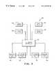
- FIG. 1is a schematic top plan view of a vehicle drive train assembly including a differential in accordance with this invention.
- FIG. 2is a top sectional elevational view of the differential illustrated in FIG. 1 .
- FIG. 3is a schematic diagram of an electronic control system for use with the differential illustrated in FIGS. 1 and 2 .
- FIG. 1a portion of a vehicle 10 containing a drive train assembly, indicated generally at 11 , in accordance with this invention.
- the drive train assembly 10includes a conventional engine 12 or other source of rotational power which is connected through a clutch 14 to a transmission 16 .
- the clutch 14 and the transmission 16are also conventional in the art.
- the clutch 14functions to selectively connect the engine 12 to the transmission 16 .
- the transmission 16contains a plurality of meshing gears of varying size which are selectively connected to provide a desired speed reduction gear ratio.
- the transmission 16is connected to a forward end of a drive shaft assembly 18 , typically through a universal joint (not shown).
- the rearward end of the drive shaft assembly 18is connected, typically through another universal joint (not shown), to a differential, indicated generally at 20 .
- a differentialindicated generally at 20 .
- the differential 20is provided to rotatably drive first and second axle shafts 22 and 24 which extend to respective rear wheels 26 of the vehicle 10 .
- a pair of front wheels 28are provided, but are not rotatably driven.
- the differential 20may be adapted to rotatably drive the front wheels 28 instead of the rear wheels 26 .
- the differential 20 of this inventionmay be used as an inter-axle differential (commonly known as a transfer case) for rotatably driving the front and rear axles of a four wheel drive vehicle.
- the differential 20includes a case 30 which is rotatably supported within an axle housing (not shown) in a known manner.
- the case 30is hollow and generally cylindrical in shape, having a pair of openings 31 formed through opposed sides thereof.
- the openings 31are provided to permit the inner ends of the axle shafts 22 and 24 to extend co-axially therethrough into the interior of the case 30 of the differential 20 .
- Respective annular seals 32such as 0 -rings, are provided within each of the openings 31 to provide a sealing engagement with each of the axle shafts 22 and 24 .
- An annular flange 30 ais formed on the exterior of the case 30 of the differential 20 .
- the annular flange 30 ais provided to facilitate the connection of a ring gear 33 to the case 30 .
- the ring gear 33may be secured to the flange 30 a of the case 30 by any conventional means, such as by a plurality of threaded fasteners (not shown).
- the ring gear 33cooperates with a pinion gear 18 a which is connected for rotation with the drive shaft assembly 18 .
- rotation of the drive shaft assembly 18causes rotation of the differential 20 about an axis which is co-axial with the axle shafts 22 and 24 in a known manner.
- the case 30is formed having a center wall 40 which divides the interior thereof into first and second fluid chambers 41 and 51 .
- the case 30is formed having a first annular plate portion 43 which extends radially inwardly and defines an enlarged central opening.
- the first annular plate portion 43divides the first chamber 41 into two fluid sub-chambers which communicate through the central opening thereof
- First and second electromagnetic coils 44 and 45are provided in the sub-chambers of the first fluid chamber 41 .
- the purpose of the first and second electromagnetic coils 44 and 45will be explained below.
- the inner end of the axle shaft 22terminates in a pair of annular shear disc portions 22 a and 22 b .
- the first shear disc portion 22 aextends radially outwardly between the first electromagnetic coil 44 and the first annular plate portion 43 of the case 30 .
- the second shear disc portion 22 bextends radially outwardly between the first annular plate portion 43 of the case 30 and the second electromagnetic coil 45 .
- the case 30is formed having a second annular plate portion 53 which extends radially inwardly and defines an enlarged central opening.
- the second annular plate portion 53divides the second chamber 51 into two fluid sub-chambers which communicate through the central opening thereof
- Third and fourth electromagnetic coils 54 and 55are provided in the sub-chambers of the second fluid chamber 51 .
- the purpose of the first and second electromagnetic coils 54 and 55will be explained below.
- the inner end of the second axle shaft 24terminates in a pair of annular shear disc portions 24 a and 24 b .
- the first shear disc portion 24 aextends radially outwardly between the third electromagnetic coil 54 and the second annular plate portion 53 of the case 30 .
- the second shear disc portion 24 bextends radially outwardly between the first annular plate portion 53 of the case 30 and the fourth electromagnetic coil 55 .
- the shear disc portions 22 a , 22 b , 24 a , and 24 bare each formed from a material having a high purity iron concentration.
- the shear disc portions 22 a , 22 b , 24 a , and 24 bare formed integrally with the respective axle shafts 22 and 24 .
- a cladding of the high purity iron materialmay be applied on each of the shear disc portions 22 a , 22 b , 24 a , and 24 b .
- the shear disc portions 22 a , 22 b , 24 a , and 24 bmay be formed as separate members which are secured to the axle shafts 22 and 24 for rotation therewith.
- shear disc portions 22 a , 22 b , 24 a , and 24 bmay be formed as separate members which are press fit, brazed, welded, splined, bolted, or otherwise secured on the ends of the axle shafts 22 and 24 .
- a “rheological fluid”is a fluid which exhibits a significant change in its ability to flow or shear upon the application of an appropriate energy field.
- the rheological fluidmay be a magneto-rheological fluid which is responsive to the presence of a magnetic field.
- Magneto-rheological fluidsmay be formed of a fluid carrier, such as silicone oil, containing magnetizable particles, such as carbonyl iron. When exposed to a magnetic field, the particles align and reduce the ability of the fluid to flow is freely.
- the rheological fluidmay alternatively be an electro-rheological fluid which is responsive to the presence of an electrical field, such as voltage. A number of such rheological fluids are commonly available.
- Meansare provided for selectively generating and applying an energy field to the rheological fluid.
- the rheological fluidis a magneto-rheological fluid.
- the means for selectively generating an energy fieldis the electromagnetic coils 44 , 45 , 54 , and 55 .
- the electromagnetic coils 44 , 45 , 54 , and 55may be arranged as illustrated or in any other manner such that when energized, a magnetic field is applied to the magneto-rheological fluid contained within the fluid chambers 41 and 51 .
- the electromagnetic coils 44 , 45 , 54 , and 55are preferably arranged so that the applied magnetic field is generally uniform over the interior of the chambers 41 and 51 containing the magneto-rheological fluid.
- the electronic control system 60includes an electronic controller 61 .
- the electronic controller 61may be embodied as a conventional microprocessor or similar computing apparatus which can be programmed to generate one or more electrical output signals in response to a plurality of electrical input signals.
- a plurality of sensorsare provided to generate input signals to the electronic controller 61 .
- a first speed sensor 62is provided which generates an electrical signal to the electronic controller 61 which is representative of the rotational speed of the axle shaft 22 .
- a second speed sensor 63is provided which generates an electrical signal to the electronic controller 61 which is representative of the rotational speed of the axle shaft 24 .
- first and second torque sensors 64 and 65may be provided which generate respective electrical signals to the electronic controller 61 which are representative of the magnitude of the torque carried by each of the axle shafts 22 and 24 .
- a first output of the electronic controller 61is connected to the first and second electromagnetic coils 44 and 45 , while a second output of the electronic controller 61 is connected to the third and fourth electromagnetic coils 54 and 55 .
- the first and second electromagnetic coils 44 and 45are connected in series, and the third and fourth electromagnetic coils 54 and 55 are connected in series.
- the electromagnetic coils 44 , 45 , 54 , and 55may be connected to the electronic controller 61 in any known manner.
- the illustrated electromagnetic coils 44 , 45 , 54 , and 55are shown as being disposed within the rotating case 30 of the differential 20 .
- Conventional slip rings(not shown) or other means may be provided for connecting the electromagnetic coils 44 , 45 , 54 , and 55 to the electronic controller 61 .
- the electromagnetic coils 44 , 45 , 54 , and 55may be disposed outside of the rotating case 30 .
- the electronic controller 61is programmed to be responsive to the input signals generated by the various sensors 62 , 63 , 64 , and 65 for controlling the operation of the electromagnetic coils 44 , 45 , 54 , and 55 and, therefore, the differential 20 as a whole.
- the differential 20is designed to distribute torque from the input drive shaft assembly 18 to the two output axle shafts 22 and 24 , while permitting the two axle shafts 22 and 24 to rotate at different speeds under certain conditions. This can be accomplished by programning the electronic controller 61 to control the amount of electrical current passing through the electromagnetic coils 44 , 45 , 54 , and 55 in response to the sensed operating conditions of the vehicle.
- the shear disk portions 22 a , 22 b , 24 a , and 24 b of the axle shafts 22 and 24are immersed in the rheological fluid contained with the fluid chambers 41 and 51 .
- electrical currentis supplied to each pair of the electromagnetic coils 44 , 45 , 54 , and 55 in equal amounts so as to create magnetic fields of equal strength in each of the fluid chambers 41 and 51 .
- the presence of these electromagnetic fieldscauses the rheological fluid to exhibit a certain amount of viscosity.
- the axle shafts 22 and 24are caused to rotate therewith. Because the viscosity of the rheological fluid is equal in both of the fluid chambers 41 and 51 , equal rotational motion and torque is imparted to each of the axles 22 and 24 and, thus, the driven rear wheels 26 of the vehicle.
- the amount of electrical current supplied to each of the electromagnetic coils 44 , 45 , 54 , and 55can be varied so as to accommodate the rotational speed and torque differential between the left axle 22 and the right axle 24 as necessary. If, for example, the speed or torque signals generated by the sensors 62 , 63 , 64 , and 65 indicate that the right wheel is slipping, the electronic controller 61 may be programmed to reduce or terminate the power being supplied to the electromagnetic coils 54 and 55 associated with the right axle shaft 24 . This causes the viscosity of the magneto-rheological fluid contained in the right chamber 51 to decrease, thereby reducing the amount of torque being supplied to the right axle shaft 24 .
- axle shafts 22 and 24can be controlled by the electronic controller 61 independently of one another in response to their respective operating conditions.
- the illustrated differential 20includes two shear disc portions 22 a and 22 b which is secured for rotation with the axle shaft 22 and two shear disc portions 24 a and 24 b which rotate with the axle shaft 24 .
- this inventionmay be practiced by having only a single shear disc portion secured for rotation with each of the axle shafts 22 and 24 .
- more than two shear disc portionsmay be secured for rotation with each of the axle shafts 22 and 24 .
- the electronic controller 61 of the illustrated differential 20is responsive to the magnitude of speed and torque of the axle shafts 22 and 24 .
- the electronic controller 61may control the operation of the differential in response to any other sensed condition of the vehicle, such as turning angle or other parameters.
Landscapes
- Engineering & Computer Science (AREA)
- General Engineering & Computer Science (AREA)
- Mechanical Engineering (AREA)
- Physics & Mathematics (AREA)
- Electromagnetism (AREA)
- Retarders (AREA)
Abstract
Description
Claims (13)
Priority Applications (2)
| Application Number | Priority Date | Filing Date | Title |
|---|---|---|---|
| US08/775,045US6183386B1 (en) | 1996-12-27 | 1996-12-27 | Differential containing rheological fluid |
| JP9361689AJPH10196765A (en) | 1996-12-27 | 1997-12-11 | Differential filled with rheological fluid |
Applications Claiming Priority (1)
| Application Number | Priority Date | Filing Date | Title |
|---|---|---|---|
| US08/775,045US6183386B1 (en) | 1996-12-27 | 1996-12-27 | Differential containing rheological fluid |
Publications (1)
| Publication Number | Publication Date |
|---|---|
| US6183386B1true US6183386B1 (en) | 2001-02-06 |
Family
ID=25103163
Family Applications (1)
| Application Number | Title | Priority Date | Filing Date |
|---|---|---|---|
| US08/775,045Expired - Fee RelatedUS6183386B1 (en) | 1996-12-27 | 1996-12-27 | Differential containing rheological fluid |
Country Status (2)
| Country | Link |
|---|---|
| US (1) | US6183386B1 (en) |
| JP (1) | JPH10196765A (en) |
Cited By (24)
| Publication number | Priority date | Publication date | Assignee | Title |
|---|---|---|---|---|
| US6527661B2 (en)* | 2000-05-12 | 2003-03-04 | Auburn Gear, Inc. | Limited slip differential having magnetorheological fluid brake |
| US6557662B1 (en)* | 2000-11-22 | 2003-05-06 | Visteon Global Technologies, Inc. | Magneto-rheological simulated steering feel system |
| US6585616B1 (en)* | 2000-11-06 | 2003-07-01 | Honda Giken Kogyo Kabushiki Kaisha | Magneto-rheological variable limited slip differential |
| US20030203788A1 (en)* | 2002-04-25 | 2003-10-30 | Louis Green | Field responsive fluids for lubrication and power transmission |
| US6723017B2 (en)* | 2002-05-09 | 2004-04-20 | Visteon Global Technologies, Inc. | Differential assembly |
| US6745879B1 (en) | 2003-02-03 | 2004-06-08 | New Venture Gear, Inc. | Hydromechanical coupling with clutch assembly and magnetorheological clutch actuator |
| US20040152553A1 (en)* | 2003-02-05 | 2004-08-05 | Moore Jason E. E. | Magnetically responsive limited slip differential |
| US20040231944A1 (en)* | 2003-02-03 | 2004-11-25 | Dolan James P. | Power transmission device for a four-wheel drive vehicle |
| US20050205375A1 (en)* | 2003-02-03 | 2005-09-22 | Magna Drivetrain Of America, Inc. | Torque transfer coupling with magnetorheological clutch actuator |
| WO2005106275A1 (en)* | 2004-04-30 | 2005-11-10 | Magna Drivetrain Ag & Co Kg | Magnetorheological clutch |
| US20050252744A1 (en)* | 2002-10-31 | 2005-11-17 | Herbert Steinwender | Magnetorheologic clutch |
| US20070125609A1 (en)* | 2005-12-07 | 2007-06-07 | O'leary Michael F | Transmission damping apparatus and method |
| US20110111913A1 (en)* | 2009-11-11 | 2011-05-12 | Ian Neal Haggerty | Differential lock assembly including coupler |
| US20110127133A1 (en)* | 2008-07-09 | 2011-06-02 | Toyota Jidosha Kabushiki Kaisha | Twin-clutch device |
| US9016155B2 (en) | 2011-10-24 | 2015-04-28 | Maxon Motor Ag | Power transmission unit for an electromotively operated drive and magneto-rheological clutch |
| DE102013019320A1 (en)* | 2013-11-20 | 2015-05-21 | GETRAG Getriebe- und Zahnradfabrik Hermann Hagenmeyer GmhH & Cie KG | Motor vehicle transmission and method for operating the same |
| WO2015113165A1 (en) | 2014-01-31 | 2015-08-06 | Société De Commercialisation Des Produits De La Recherche Appliquée Socpra Sciences Et Génie S.E.C. | Magnetorheological fluid clutch apparatus and control systems |
| US20160221672A1 (en)* | 2014-01-31 | 2016-08-04 | Bell Helicopter Textron Inc. | Magnetorheological Haptic Trim Actuator |
| US20160221674A1 (en)* | 2015-01-30 | 2016-08-04 | Bell Helicopter Textron Inc. | Magnetorheological Actuator With Torsional Spring |
| US10677087B2 (en) | 2018-05-11 | 2020-06-09 | General Electric Company | Support structure for geared turbomachine |
| US10788085B2 (en) | 2014-01-31 | 2020-09-29 | Societe De Commercialisation Des Produits De La Recherche Appliquee Socpra Sciences Et Genie S.E.C. | Magnetorheological fluid clutch apparatus and control systems |
| US10823003B2 (en) | 2018-05-25 | 2020-11-03 | General Electric Company | System and method for mitigating undesired vibrations at a turbo machine |
| US11092201B2 (en)* | 2016-10-13 | 2021-08-17 | Exonetik Inc. | Multiple MR fluid clutch apparatuses sharing MR fluid |
| US11493407B2 (en) | 2018-09-28 | 2022-11-08 | Ge Avio S.R.L. | Torque measurement system |
Families Citing this family (2)
| Publication number | Priority date | Publication date | Assignee | Title |
|---|---|---|---|---|
| KR20040041968A (en)* | 2002-11-12 | 2004-05-20 | 현대자동차주식회사 | limited slip differential utilized of ER fluid |
| KR20040049638A (en)* | 2002-12-06 | 2004-06-12 | 현대자동차주식회사 | Differential limited device of vehicle |
Citations (15)
| Publication number | Priority date | Publication date | Assignee | Title |
|---|---|---|---|---|
| US2983349A (en) | 1957-10-17 | 1961-05-09 | Gen Electric | Magnetic clutch |
| US4444298A (en)* | 1981-07-10 | 1984-04-24 | The Secretary Of State For Defence In Her Britannic Majesty's Government Of The United Kingdom Of Great Britain And Northern Ireland | Viscous shear clutch |
| US5007513A (en)* | 1990-04-03 | 1991-04-16 | Lord Corporation | Electroactive fluid torque transmission apparatus with ferrofluid seal |
| US5054593A (en) | 1990-01-10 | 1991-10-08 | Lord Corporation | Electrophoretic fluid torque transmission apparatus and method |
| US5090531A (en) | 1990-01-10 | 1992-02-25 | Lord Corporation | Electrophoretic fluid differential |
| US5147252A (en) | 1988-06-15 | 1992-09-15 | Group Lotus P/C | Differential unit |
| US5322484A (en) | 1992-12-22 | 1994-06-21 | Dana Corporation | Locking differential with clutch activated by electrorheological fluid coupling |
| US5358084A (en)* | 1993-01-19 | 1994-10-25 | Chrysler Corporation | Torque magnitude control using electrorheological fluids |
| US5452957A (en) | 1994-11-22 | 1995-09-26 | Dana Corporation | Center bearing assembly including support member containing rheological fluid |
| US5598908A (en)* | 1995-06-05 | 1997-02-04 | Gse, Inc. | Magnetorheological fluid coupling device and torque load simulator system |
| US5657829A (en)* | 1994-05-31 | 1997-08-19 | Zexel Torsen Inc. | Hybrid control system for limiting engine output |
| US5779013A (en)* | 1996-07-18 | 1998-07-14 | New Venture Gear, Inc. | Torque transfer apparatus using magnetorheological fluids |
| US5823309A (en)* | 1997-05-23 | 1998-10-20 | General Motors Corporation | Magnetorheological transmission clutch |
| US5848678A (en)* | 1997-06-04 | 1998-12-15 | General Motors Corporation | Passive magnetorheological clutch |
| US5915513A (en)* | 1997-08-26 | 1999-06-29 | Borg-Warner Automotive, Inc. | Clutch with magneto-rheological operator for transfer cases and the like |
- 1996
- 1996-12-27USUS08/775,045patent/US6183386B1/ennot_activeExpired - Fee Related
- 1997
- 1997-12-11JPJP9361689Apatent/JPH10196765A/enactivePending
Patent Citations (16)
| Publication number | Priority date | Publication date | Assignee | Title |
|---|---|---|---|---|
| US2983349A (en) | 1957-10-17 | 1961-05-09 | Gen Electric | Magnetic clutch |
| US4444298A (en)* | 1981-07-10 | 1984-04-24 | The Secretary Of State For Defence In Her Britannic Majesty's Government Of The United Kingdom Of Great Britain And Northern Ireland | Viscous shear clutch |
| US5147252A (en) | 1988-06-15 | 1992-09-15 | Group Lotus P/C | Differential unit |
| US5054593A (en) | 1990-01-10 | 1991-10-08 | Lord Corporation | Electrophoretic fluid torque transmission apparatus and method |
| US5090531A (en) | 1990-01-10 | 1992-02-25 | Lord Corporation | Electrophoretic fluid differential |
| US5007513A (en)* | 1990-04-03 | 1991-04-16 | Lord Corporation | Electroactive fluid torque transmission apparatus with ferrofluid seal |
| US5322484A (en) | 1992-12-22 | 1994-06-21 | Dana Corporation | Locking differential with clutch activated by electrorheological fluid coupling |
| US5358084A (en)* | 1993-01-19 | 1994-10-25 | Chrysler Corporation | Torque magnitude control using electrorheological fluids |
| US5657829A (en)* | 1994-05-31 | 1997-08-19 | Zexel Torsen Inc. | Hybrid control system for limiting engine output |
| US5452957A (en) | 1994-11-22 | 1995-09-26 | Dana Corporation | Center bearing assembly including support member containing rheological fluid |
| US5598908A (en)* | 1995-06-05 | 1997-02-04 | Gse, Inc. | Magnetorheological fluid coupling device and torque load simulator system |
| US5779013A (en)* | 1996-07-18 | 1998-07-14 | New Venture Gear, Inc. | Torque transfer apparatus using magnetorheological fluids |
| US5845753A (en)* | 1996-07-18 | 1998-12-08 | New Venture Gear, Inc. | Torque transfer apparatus using magnetorheological fluids |
| US5823309A (en)* | 1997-05-23 | 1998-10-20 | General Motors Corporation | Magnetorheological transmission clutch |
| US5848678A (en)* | 1997-06-04 | 1998-12-15 | General Motors Corporation | Passive magnetorheological clutch |
| US5915513A (en)* | 1997-08-26 | 1999-06-29 | Borg-Warner Automotive, Inc. | Clutch with magneto-rheological operator for transfer cases and the like |
Cited By (46)
| Publication number | Priority date | Publication date | Assignee | Title |
|---|---|---|---|---|
| US6527661B2 (en)* | 2000-05-12 | 2003-03-04 | Auburn Gear, Inc. | Limited slip differential having magnetorheological fluid brake |
| AU781510B2 (en)* | 2000-05-12 | 2005-05-26 | Auburn Gear, Inc. | Limited slip differential having magnetorheological fluid brake |
| US6585616B1 (en)* | 2000-11-06 | 2003-07-01 | Honda Giken Kogyo Kabushiki Kaisha | Magneto-rheological variable limited slip differential |
| US6557662B1 (en)* | 2000-11-22 | 2003-05-06 | Visteon Global Technologies, Inc. | Magneto-rheological simulated steering feel system |
| US20030203788A1 (en)* | 2002-04-25 | 2003-10-30 | Louis Green | Field responsive fluids for lubrication and power transmission |
| US6729996B2 (en)* | 2002-04-25 | 2004-05-04 | General Motors Corporation | Field responsive fluids for lubrication and power transmission |
| US6723017B2 (en)* | 2002-05-09 | 2004-04-20 | Visteon Global Technologies, Inc. | Differential assembly |
| US7461731B2 (en) | 2002-10-31 | 2008-12-09 | Magna Drivetrain Ag & Co Kg | Magnetorheologic clutch |
| US20080142328A1 (en)* | 2002-10-31 | 2008-06-19 | Magna Drivetrain Ag & Co Kg | Magnetorheologic Clutch |
| US7325663B2 (en)* | 2002-10-31 | 2008-02-05 | Magna Drivetrain Ag &Co Kg | Magnetorheologic clutch |
| US20050252744A1 (en)* | 2002-10-31 | 2005-11-17 | Herbert Steinwender | Magnetorheologic clutch |
| US20040231944A1 (en)* | 2003-02-03 | 2004-11-25 | Dolan James P. | Power transmission device for a four-wheel drive vehicle |
| US6988602B2 (en) | 2003-02-03 | 2006-01-24 | Magna Powertrain, Inc. | Torque transfer coupling with magnetorheological clutch actuator |
| US6745879B1 (en) | 2003-02-03 | 2004-06-08 | New Venture Gear, Inc. | Hydromechanical coupling with clutch assembly and magnetorheological clutch actuator |
| US6932204B2 (en) | 2003-02-03 | 2005-08-23 | Magna Drivetrain Of America, Inc. | Power transmission device for a four-wheel drive vehicle |
| US20050205375A1 (en)* | 2003-02-03 | 2005-09-22 | Magna Drivetrain Of America, Inc. | Torque transfer coupling with magnetorheological clutch actuator |
| US20040168875A1 (en)* | 2003-02-03 | 2004-09-02 | Dolan James P. | Hydromechanical coupling with clutch assembly and magnetorheological clutch actuator |
| US6811007B2 (en) | 2003-02-03 | 2004-11-02 | New Venture Gear, Inc. | Hydromechanical coupling with clutch assembly and magnetorheological clutch actuator |
| US7083030B2 (en) | 2003-02-03 | 2006-08-01 | Magna Drivertrain Of America, Inc. | Torque transfer coupling with magnetorheological clutch actuator |
| US6991576B2 (en) | 2003-02-05 | 2006-01-31 | American Axle & Manufacturing, Inc. | Magnetically responsive limited slip differential |
| US20050064978A1 (en)* | 2003-02-05 | 2005-03-24 | Moore Jason E. E. | Magnetically responsive limited slip differential |
| US20040152553A1 (en)* | 2003-02-05 | 2004-08-05 | Moore Jason E. E. | Magnetically responsive limited slip differential |
| US6817961B2 (en) | 2003-02-05 | 2004-11-16 | American Axle & Manufacturing, Inc. | Magnetically responsive limited slip differential |
| WO2005106275A1 (en)* | 2004-04-30 | 2005-11-10 | Magna Drivetrain Ag & Co Kg | Magnetorheological clutch |
| US20080236976A1 (en)* | 2004-04-30 | 2008-10-02 | Magna Drivetrain Ag & Co Kg | Magnetorheological Clutch |
| US7588131B2 (en)* | 2004-04-30 | 2009-09-15 | Magna Drivetrain Ag & Co Kg | Magnetorheological clutch |
| US20070125609A1 (en)* | 2005-12-07 | 2007-06-07 | O'leary Michael F | Transmission damping apparatus and method |
| US20110127133A1 (en)* | 2008-07-09 | 2011-06-02 | Toyota Jidosha Kabushiki Kaisha | Twin-clutch device |
| US8678153B2 (en)* | 2008-07-09 | 2014-03-25 | Toyota Jidosha Kabushiki Kaisha | Twin-clutch device |
| US20110111913A1 (en)* | 2009-11-11 | 2011-05-12 | Ian Neal Haggerty | Differential lock assembly including coupler |
| US8292774B2 (en) | 2009-11-11 | 2012-10-23 | Honda Motor Company, Ltd. | Differential lock assembly including coupler |
| US9016155B2 (en) | 2011-10-24 | 2015-04-28 | Maxon Motor Ag | Power transmission unit for an electromotively operated drive and magneto-rheological clutch |
| DE102013019320A1 (en)* | 2013-11-20 | 2015-05-21 | GETRAG Getriebe- und Zahnradfabrik Hermann Hagenmeyer GmhH & Cie KG | Motor vehicle transmission and method for operating the same |
| CN105934599A (en)* | 2014-01-31 | 2016-09-07 | 索科普哈应用研究产品商业化公司基因科学Sec | Magnetorheological fluid clutch apparatus and control systems |
| US20160221672A1 (en)* | 2014-01-31 | 2016-08-04 | Bell Helicopter Textron Inc. | Magnetorheological Haptic Trim Actuator |
| WO2015113165A1 (en) | 2014-01-31 | 2015-08-06 | Société De Commercialisation Des Produits De La Recherche Appliquée Socpra Sciences Et Génie S.E.C. | Magnetorheological fluid clutch apparatus and control systems |
| US9656746B2 (en)* | 2014-01-31 | 2017-05-23 | Bell Helicopter Textron Inc. | Magnetorheological haptic trim actuator |
| EP3099954A4 (en)* | 2014-01-31 | 2017-12-13 | Société de commercialisation des produits de la recherche appliquée SOCPRA Sciences Santé et Humaines s.e.c. | Magnetorheological fluid clutch apparatus and control systems |
| US10012273B2 (en) | 2014-01-31 | 2018-07-03 | Societe De Commercialisation Des Produits De La Recherche Appliquee Socpra Sciences Et Genie S.E.C. | Magnetorheological fluid clutch apparatus and control systems |
| US10788085B2 (en) | 2014-01-31 | 2020-09-29 | Societe De Commercialisation Des Produits De La Recherche Appliquee Socpra Sciences Et Genie S.E.C. | Magnetorheological fluid clutch apparatus and control systems |
| US20160221674A1 (en)* | 2015-01-30 | 2016-08-04 | Bell Helicopter Textron Inc. | Magnetorheological Actuator With Torsional Spring |
| US9656745B2 (en)* | 2015-01-30 | 2017-05-23 | Bell Helicopter Textron Inc. | Magnetorheological actuator with torsional spring |
| US11092201B2 (en)* | 2016-10-13 | 2021-08-17 | Exonetik Inc. | Multiple MR fluid clutch apparatuses sharing MR fluid |
| US10677087B2 (en) | 2018-05-11 | 2020-06-09 | General Electric Company | Support structure for geared turbomachine |
| US10823003B2 (en) | 2018-05-25 | 2020-11-03 | General Electric Company | System and method for mitigating undesired vibrations at a turbo machine |
| US11493407B2 (en) | 2018-09-28 | 2022-11-08 | Ge Avio S.R.L. | Torque measurement system |
Also Published As
| Publication number | Publication date |
|---|---|
| JPH10196765A (en) | 1998-07-31 |
Similar Documents
| Publication | Publication Date | Title |
|---|---|---|
| US6183386B1 (en) | Differential containing rheological fluid | |
| US6817434B1 (en) | Active hydraulically actuated on-demand wheel end assembly | |
| US5083986A (en) | Coupling apparatus with double clutches | |
| EP1762754B1 (en) | Vehicle differential including pump with variable-engagement clutch | |
| EP0262434B1 (en) | Interaxle differential restriction device for vehicle four wheel drive systems | |
| EP0524707B1 (en) | Transmission system for a two and four-wheel drive motor vehicle | |
| JP3683062B2 (en) | Power transmission device for vehicle | |
| JPH045128A (en) | Vehicle differential limiting control device | |
| US6712730B2 (en) | Active torque bias coupling | |
| JPS6231529A (en) | Driving force distribution control device for 4-wheel drive vehicles | |
| JPS61169326A (en) | Driving force distribution controller for 4 wheel drive car | |
| EP0409529B1 (en) | Torque distribution control system for a four-wheel drive motor vehicle | |
| JPH0729555B2 (en) | Drive force distribution controller for four-wheel drive vehicle | |
| JPH10194005A (en) | Four-wheel drive vehicle | |
| EP0314420A1 (en) | Viscous clutch assembly for torque transmission in motor vehicle | |
| US6755290B1 (en) | Power transmission device for a four-wheel drive vehicle | |
| US6991576B2 (en) | Magnetically responsive limited slip differential | |
| US4744437A (en) | Power transmitting system for a four-wheel drive vehicle | |
| WO2003083326A9 (en) | Axle center with active torque bias control | |
| JP2005516161A (en) | Transmission case with improved torque bias capability | |
| WO2008088596A1 (en) | Torque vectoring system | |
| JPS62103227A (en) | Differential limiting controller for car | |
| JPH03219123A (en) | Coupling device | |
| US4815336A (en) | Power transfer device for four-wheel drive | |
| JPS61191431A (en) | Driving force distribution control device for 4-wheel-drive vehicle |
Legal Events
| Date | Code | Title | Description |
|---|---|---|---|
| AS | Assignment | Owner name:DANA CORPORATION, OHIO Free format text:ASSIGNMENT OF ASSIGNORS INTEREST;ASSIGNOR:DUGGAN, JAMES A.;REEL/FRAME:008348/0350 Effective date:19961227 | |
| AS | Assignment | Owner name:SPICER DRIVESHAFT, INC., OHIO Free format text:ASSIGNMENT OF ASSIGNORS INTEREST;ASSIGNOR:DANA CORPORATION, A VIRGINIA CORPORATION;REEL/FRAME:011667/0621 Effective date:20001221 | |
| AS | Assignment | Owner name:SPICER DRIVESHAFT, INC., OHIO Free format text:ASSIGNMENT OF ASSIGNORS INTEREST;ASSIGNOR:DANA CORPORATION;REEL/FRAME:011705/0638 Effective date:20010323 | |
| AS | Assignment | Owner name:TORQUE-TRACTION TECHNOLOGIES, INC., OHIO Free format text:CHANGE OF NAME;ASSIGNOR:SPICER DRIVESHAFT, INC.;REEL/FRAME:013933/0631 Effective date:20021231 | |
| FEPP | Fee payment procedure | Free format text:PAYER NUMBER DE-ASSIGNED (ORIGINAL EVENT CODE: RMPN); ENTITY STATUS OF PATENT OWNER: LARGE ENTITY Free format text:PAYOR NUMBER ASSIGNED (ORIGINAL EVENT CODE: ASPN); ENTITY STATUS OF PATENT OWNER: LARGE ENTITY | |
| FPAY | Fee payment | Year of fee payment:4 | |
| AS | Assignment | Owner name:TORQUE-TRACTION TECHNOLOGIES LLC,OHIO Free format text:MERGER;ASSIGNOR:TORQUE-TRACTION TECHNOLOGY, INC.;REEL/FRAME:017240/0259 Effective date:20060101 Owner name:TORQUE-TRACTION TECHNOLOGIES LLC, OHIO Free format text:MERGER;ASSIGNOR:TORQUE-TRACTION TECHNOLOGY, INC.;REEL/FRAME:017240/0259 Effective date:20060101 | |
| REMI | Maintenance fee reminder mailed | ||
| LAPS | Lapse for failure to pay maintenance fees | ||
| STCH | Information on status: patent discontinuation | Free format text:PATENT EXPIRED DUE TO NONPAYMENT OF MAINTENANCE FEES UNDER 37 CFR 1.362 | |
| FP | Lapsed due to failure to pay maintenance fee | Effective date:20090206 |