US6181971B1 - Joining conductor cables and electrodes on a multi-lumen lead body - Google Patents
Joining conductor cables and electrodes on a multi-lumen lead bodyDownload PDFInfo
- Publication number
- US6181971B1 US6181971B1US09/208,234US20823498AUS6181971B1US 6181971 B1US6181971 B1US 6181971B1US 20823498 AUS20823498 AUS 20823498AUS 6181971 B1US6181971 B1US 6181971B1
- Authority
- US
- United States
- Prior art keywords
- lead body
- electrode
- lead
- lumen
- implantable medical
- Prior art date
- Legal status (The legal status is an assumption and is not a legal conclusion. Google has not performed a legal analysis and makes no representation as to the accuracy of the status listed.)
- Expired - Lifetime
Links
- 239000004020conductorSubstances0.000titleclaimsabstractdescription39
- 230000035939shockEffects0.000claimsabstractdescription11
- 230000002093peripheral effectEffects0.000claimsdescription7
- 238000003466weldingMethods0.000abstractdescription15
- 238000010276constructionMethods0.000description8
- 238000002788crimpingMethods0.000description2
- 238000005516engineering processMethods0.000description2
- 239000000463materialSubstances0.000description2
- 230000013011matingEffects0.000description2
- 238000000034methodMethods0.000description2
- 238000013153catheter ablationMethods0.000description1
- 210000001174endocardiumAnatomy0.000description1
- 238000003780insertionMethods0.000description1
- 230000037431insertionEffects0.000description1
- 238000009413insulationMethods0.000description1
- 238000001990intravenous administrationMethods0.000description1
- 230000007246mechanismEffects0.000description1
- 239000002184metalSubstances0.000description1
- 238000012986modificationMethods0.000description1
- 230000004048modificationEffects0.000description1
- 239000004033plasticSubstances0.000description1
- 229920003023plasticPolymers0.000description1
- 229920002635polyurethanePolymers0.000description1
- 239000004814polyurethaneSubstances0.000description1
- 229920002379silicone rubberPolymers0.000description1
- 239000004945silicone rubberSubstances0.000description1
Images


Classifications
- A—HUMAN NECESSITIES
- A61—MEDICAL OR VETERINARY SCIENCE; HYGIENE
- A61N—ELECTROTHERAPY; MAGNETOTHERAPY; RADIATION THERAPY; ULTRASOUND THERAPY
- A61N1/00—Electrotherapy; Circuits therefor
- A61N1/02—Details
- A61N1/04—Electrodes
- A61N1/05—Electrodes for implantation or insertion into the body, e.g. heart electrode
- A61N1/056—Transvascular endocardial electrode systems
- A61N1/0563—Transvascular endocardial electrode systems specially adapted for defibrillation or cardioversion
- A—HUMAN NECESSITIES
- A61—MEDICAL OR VETERINARY SCIENCE; HYGIENE
- A61N—ELECTROTHERAPY; MAGNETOTHERAPY; RADIATION THERAPY; ULTRASOUND THERAPY
- A61N1/00—Electrotherapy; Circuits therefor
- A61N1/02—Details
- A61N1/04—Electrodes
- A61N1/05—Electrodes for implantation or insertion into the body, e.g. heart electrode
- Y—GENERAL TAGGING OF NEW TECHNOLOGICAL DEVELOPMENTS; GENERAL TAGGING OF CROSS-SECTIONAL TECHNOLOGIES SPANNING OVER SEVERAL SECTIONS OF THE IPC; TECHNICAL SUBJECTS COVERED BY FORMER USPC CROSS-REFERENCE ART COLLECTIONS [XRACs] AND DIGESTS
- Y10—TECHNICAL SUBJECTS COVERED BY FORMER USPC
- Y10S—TECHNICAL SUBJECTS COVERED BY FORMER USPC CROSS-REFERENCE ART COLLECTIONS [XRACs] AND DIGESTS
- Y10S174/00—Electricity: conductors and insulators
- Y10S174/08—Shrinkable tubes
- Y—GENERAL TAGGING OF NEW TECHNOLOGICAL DEVELOPMENTS; GENERAL TAGGING OF CROSS-SECTIONAL TECHNOLOGIES SPANNING OVER SEVERAL SECTIONS OF THE IPC; TECHNICAL SUBJECTS COVERED BY FORMER USPC CROSS-REFERENCE ART COLLECTIONS [XRACs] AND DIGESTS
- Y10—TECHNICAL SUBJECTS COVERED BY FORMER USPC
- Y10T—TECHNICAL SUBJECTS COVERED BY FORMER US CLASSIFICATION
- Y10T29/00—Metal working
- Y10T29/49—Method of mechanical manufacture
- Y10T29/49002—Electrical device making
- Y10T29/49117—Conductor or circuit manufacturing
- Y10T29/49174—Assembling terminal to elongated conductor
- Y10T29/49179—Assembling terminal to elongated conductor by metal fusion bonding
Definitions
- the present inventionrelates generally to electrical leads for connecting implantable medical devices with selected body tissue to be stimulated by such devices, and more particularly to techniques for providing a secure electrical and mechanical connection between an elongated conductor cable and a mating electrode.
- implantable defibrillation leadstypically employ elongated coils as electrodes. These electrode coils are coupled at one or both ends to an elongated conductor extending through the lead body to the electrode.
- Transvenous pacing leads, cardiac ablation catheters and other electrode bearing leads and cathetersmay also employ coil electrodes.
- welding, crimping, and swagingit is desirable that such connections between the conductor and the electrode provide a highly reliable electrical connection, with good mechanical properties including high tensile strength. It is also desirable that such connections allow for the lead assembly itself to retain a high degree of tensile strength through the area of the electrode.
- pacing and defibrillation leadshave taken the form of single or multifilar wire coils.
- stranded wire conductorssuch as cables, instead of coiled wire conductors.
- Such stranded conductorspresent a new set of requirements for interconnection with electrode coils, if the above described design goals are to be accomplished.
- the present inventionrelates to this more recent lead technology.
- the present inventionrelates to an implantable medical electrical lead made by forming a generally radially directed bore extending between each lumen of an elongated lead body having a plurality of internal longitudinally extending, circumferentially spaced lumina.
- the boresare located at longitudinally and circumferentially spaced locations and an elongated conductor cable is then drawn into and through each lumen of the lead body such that a terminal end thereof projects through and beyond an associated one of the bores.
- a metallic tubeis slidably attached onto each conductor cable adjacent the cable's terminal end, then is firmly joined to its associated conductor cable.
- each metallic tubeis affixed, as by welding, preferably, by laser welding, to an associated one of a plurality of tubular electrodes coaxial with, and overlying, the lead body at longitudinally spaced locations.
- the tubular electrodemay be a ring electrode with the lead body connected to a pacemaker.
- the tubular electrodemay be a shock coil electrode with the lead body connected to a defibrillator.
- the cable endis drawn out from the inner lumen via a small pre-pierced hole on the multi-lumen insulation lead body tubing.
- a metallic tubeis installed over the cable located outside the lead body.
- the metallic tube(such as Pt/Ir or MP35N) is crimped or compressed or otherwise operated upon to provide a permanent connection between the cable and the metallic tube.
- the ring electrode for a Brady lead or a shock coil electrodeis then installed over the lead body and the crimped tube. Welding, and preferably laser welding, is used to provide permanent electrical connection between the electrode and the crimped tube.
- a primary feature, then, of the present inventionis the provision of an improved electrical lead for connecting an implantable medical device with selected body tissue to be stimulated by such device.
- Another feature of the present inventionis the provision of such an electrical lead which can be readily manufactured from commonly available materials.
- Still another feature of the present inventionis the provision of such an electrical lead which can be inexpensively manufactured while maintaining the performance achieved by much more expensive electrode designs.
- Yet a further feature of the present inventionis the provision of a technique for providing a secure electrical and mechanical connection between an elongated conductor cable and a mating electrode.
- Still a further feature of the present inventionis the provision of such an electrical lead constructed by drawing an elongated conductor cable first through each lumen of an elongated multi-lumen lead body, then into and through a generally radially directed bore extending between each lumen and the outer peripheral surface of the lead body, the generally radially directed bores being located at longitudinally spaced locations, such that a terminal end of the cable projects through, and beyond, an associated one of the generally radially directed bores, then slidably attaching a metallic tube onto each conductor cable adjacent its terminal end, then firmly joining each metallic tube and its associated conductor cable, and then affixing each metallic tube to an associated one of a plurality of tubular electrodes coaxial with, and overlying, the lead body at longitudinally spaced locations.
- each electrodeis affixed to its associated metallic tube by welding and, preferably, by laser welding.
- Still another feature of the present inventionis the provision of such an electrical lead wherein each tubular electrode is a ring electrode; and wherein the lead body is connected to a pacemaker.
- each tubular electrodeis a shock coil electrode and wherein the lead body is connected to a defibrillator.
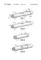
- FIG. 1is a perspective view of an implantable medical electrical lead embodying the present invention, at an interim stage of its construction;
- FIG. 2is a cross-section view taken generally along line 2 — 2 in FIG. 1;
- FIG. 3is a perspective view of the implantable medical electrical lead of FIG. 1 but illustrating a subsequent stage of its construction
- FIG. 4is a perspective view of the implantable medical electrical lead of FIG. 1 but illustrating yet a further stage of its construction
- FIG. 5is a perspective view of the implantable medical electrical lead of FIG. 1 but illustrating a final stage of its construction, being one embodiment of the invention
- FIG. 6is a diagrammatic side elevation view, partly cut away and in section, illustrating a pacemaker lead embodying the invention
- FIG. 7is a perspective view of the implantable medical electrical lead of FIG. 1 but illustrating a final stage of its construction, being another embodiment of the invention
- FIG. 8is a diagrammatic side elevation view, partly cut away and in section, illustrating a defibrillator lead embodying the invention.
- FIG. 9is a side elevation view, in section, illustrating a prior art electrical lead.
- FIGS. 1 and 2generally illustrate an implantable medical electrical lead 20 embodying the present invention.
- the lead 20may be of the type designed for intravenous insertion for contact with the endocardium, and as such may be conventionally referred to as an endocardial lead. However, the invention need not be so limited.
- the lead 20is provided with an elongated lead body 22 preferably fabricated of silicone rubber, polyurethane, or other suitable plastic material.
- the lead bodyhas a plurality of internal longitudinally extending, circumferentially spaced lumina 24 and a plurality of generally radially directed bores 26 extending between each lumen and the outer peripheral surface 28 at longitudinally spaced locations.
- the lumina 24are generally equally spaced circumferentially and are generally centered on an arc which has the same radial distance from a longitudinal axis 29 of the lead body 22 .
- An elongated conductor cable 30is received in and extends along each lumen 24 of the lead body 22 to a terminal end 32 which projects through and beyond an associated one of the generally radially directed bores 26 .
- the conductor cableis typically of small multi-strand construction. It may be, for example, 0.006 inch diameter cable consisting of seven wires, in which the wire O.D is 0.002 inches. It may also be of a single strand or of more than seven strands.
- a metallic tube 34is slidably applied to, or received on, each conductor cable 30 adjacent its terminal end 32 (see FIG. 3 ), then firmly joined (see FIG. 4) to the conductor cable. This step is preferably performed by crimping although it may be performed in some other suitable manner, by welding, for example. After the joint has been achieved, it is desirable to sever and remove any part of the cable 30 which extends beyond the crimped metallic tube 34 .
- a terminated electrical lead 40is illustrated in FIG. 5 and depicts one embodiment of the invention.
- a plurality of tubular, or ring, electrodes 42are coaxial with, and overlie the lead body 22 , specifically overlying each conductor cable 30 to which has been joined a metallic tube 34 .
- Each electrode 42is then affixed, as by welding and preferably, by laser welding, to an associated one of the metallic tubes 34 .
- each electrodeis formed with an aperture 44 through which a laser beam can be directed onto the metallic tube 34 underlying the electrode.
- the terminated electrical lead 40is intended to be employed in conjunction with a pacemaker 46 (FIG. 6) to which it is suitably connected.
- a terminated electrical lead 50is illustrated in FIG. 7 and depicts another embodiment of the invention.
- a plurality of shock coil electrodes 52are coaxial with, and overlie the lead body 22 .
- each shock coil electrode 52specifically overlies each conductor cable 30 to which has been joined a metallic tube 34 .
- Each shock coil electrode 52is then affixed, as by welding and preferably, by laser welding, to an associated one of the metallic tubes 34 .
- there is no equivalent to the aperture 44since free ends 54 of the shock coil electrode 52 are openly exposed enabling the free manipulation of a laser beam so it can be directed onto the metallic tube 34 underlying the electrode.
- the terminated electrical lead 50is intended to be employed in conjunction with a defibrillator 56 (FIG. 8) to which it is suitably connected.
- Such a known electrical lead 60employs coiled conductors 62 , 64 , for example, to connect a pacemaker, defibrillator, or other pulse generating device to its associated electrode.
- the conductors 62 , 64are coaxial and are appropriately supported and separated by coaxial insulative tubing.
- the diameter of the electrical lead 60necessarily increases to accommodate an additional conductor and an additional insulative tube. This is highly undesirable and is overcome by the invention presented above.
Landscapes
- Health & Medical Sciences (AREA)
- Heart & Thoracic Surgery (AREA)
- Cardiology (AREA)
- Radiology & Medical Imaging (AREA)
- Biomedical Technology (AREA)
- Nuclear Medicine, Radiotherapy & Molecular Imaging (AREA)
- Engineering & Computer Science (AREA)
- Life Sciences & Earth Sciences (AREA)
- Animal Behavior & Ethology (AREA)
- General Health & Medical Sciences (AREA)
- Public Health (AREA)
- Veterinary Medicine (AREA)
- Vascular Medicine (AREA)
- Electrotherapy Devices (AREA)
Abstract
Description
The present invention relates generally to electrical leads for connecting implantable medical devices with selected body tissue to be stimulated by such devices, and more particularly to techniques for providing a secure electrical and mechanical connection between an elongated conductor cable and a mating electrode.
It has been known that implantable defibrillation leads, especially transvenous leads, typically employ elongated coils as electrodes. These electrode coils are coupled at one or both ends to an elongated conductor extending through the lead body to the electrode. Transvenous pacing leads, cardiac ablation catheters and other electrode bearing leads and catheters may also employ coil electrodes. Over the years, quite a large number of different mechanisms for interconnecting coil electrodes and conductors have been proposed including welding, crimping, and swaging. It is desirable that such connections between the conductor and the electrode provide a highly reliable electrical connection, with good mechanical properties including high tensile strength. It is also desirable that such connections allow for the lead assembly itself to retain a high degree of tensile strength through the area of the electrode.
Typically, conductors in commercially marketed pacing and defibrillation leads have taken the form of single or multifilar wire coils. However, there has been a high level of recent interest in pacing and defibrillation leads employing stranded wire conductors such as cables, instead of coiled wire conductors. Such stranded conductors present a new set of requirements for interconnection with electrode coils, if the above described design goals are to be accomplished. The present invention relates to this more recent lead technology.
Typical of the prior art in this regard is U.S. Pat. No. 5,591,142 to Van Erp which discloses encasing wires within a metal sleeve and U.S. Pat. No. 5,676,694 to Boser et al. which discloses laser welding an electrode to a sleeve and covering the electrode with a polymeric sleeve.
Other patents, as follows, disclose positioning wires outside of a conductor with subsequent mounting thereon of an electrode or the like:
| Pat. No. | Inventor(s) | Issued |
| 5,632,274 | Quedens et al. | 05/27/97 |
| 5,499,981 | Kordis | 03/19/96 |
| 5,409,652 | Carter | 04/25/95 |
| 5,251,643 | Osypka | 10/12/93 |
| 4,777,955 | Brayton et al. | 10/18/88 |
| 4,522,212 | Gelinas et al. | 06/11/85 |
it was with knowledge of the foregoing state of the technology that the present invention has been conceived and is now reduced to practice.
The present invention relates to an implantable medical electrical lead made by forming a generally radially directed bore extending between each lumen of an elongated lead body having a plurality of internal longitudinally extending, circumferentially spaced lumina. The bores are located at longitudinally and circumferentially spaced locations and an elongated conductor cable is then drawn into and through each lumen of the lead body such that a terminal end thereof projects through and beyond an associated one of the bores. A metallic tube is slidably attached onto each conductor cable adjacent the cable's terminal end, then is firmly joined to its associated conductor cable. Thereupon, each metallic tube is affixed, as by welding, preferably, by laser welding, to an associated one of a plurality of tubular electrodes coaxial with, and overlying, the lead body at longitudinally spaced locations. In one instance, the tubular electrode may be a ring electrode with the lead body connected to a pacemaker. In another instance, the tubular electrode may be a shock coil electrode with the lead body connected to a defibrillator.
It has been a great challenge to electrically and reliably connect a small multi-strand conductor cable (for example: 0.006 inch cable consisting of 7 wires, in which the wire O.D is 0.002 inches) to a ring electrode or a multifilar shock coil electrode. Being of such small size, the connection is a very difficult one to make and, once made, is very fragile and unlikely to endure for a multi-lumen lead body, where the cable is brought out from the inner lumen and attached to the electrode. The invention described herein, however, provides an easy, practical and reliable connection between such a small cable and an electrode on a multi-lumen lead body.
At the location of the electrode on the multi-lumen lead body, the cable end is drawn out from the inner lumen via a small pre-pierced hole on the multi-lumen insulation lead body tubing. A metallic tube is installed over the cable located outside the lead body. The metallic tube (such as Pt/Ir or MP35N) is crimped or compressed or otherwise operated upon to provide a permanent connection between the cable and the metallic tube. The ring electrode for a Brady lead or a shock coil electrode is then installed over the lead body and the crimped tube. Welding, and preferably laser welding, is used to provide permanent electrical connection between the electrode and the crimped tube.
A primary feature, then, of the present invention is the provision of an improved electrical lead for connecting an implantable medical device with selected body tissue to be stimulated by such device.
Another feature of the present invention is the provision of such an electrical lead which can be readily manufactured from commonly available materials.
Still another feature of the present invention is the provision of such an electrical lead which can be inexpensively manufactured while maintaining the performance achieved by much more expensive electrode designs.
Yet a further feature of the present invention is the provision of a technique for providing a secure electrical and mechanical connection between an elongated conductor cable and a mating electrode.
Still a further feature of the present invention is the provision of such an electrical lead constructed by drawing an elongated conductor cable first through each lumen of an elongated multi-lumen lead body, then into and through a generally radially directed bore extending between each lumen and the outer peripheral surface of the lead body, the generally radially directed bores being located at longitudinally spaced locations, such that a terminal end of the cable projects through, and beyond, an associated one of the generally radially directed bores, then slidably attaching a metallic tube onto each conductor cable adjacent its terminal end, then firmly joining each metallic tube and its associated conductor cable, and then affixing each metallic tube to an associated one of a plurality of tubular electrodes coaxial with, and overlying, the lead body at longitudinally spaced locations.
Yet another feature of the present invention is the provision of such an electrical lead wherein each electrode is affixed to its associated metallic tube by welding and, preferably, by laser welding.
Still another feature of the present invention is the provision of such an electrical lead wherein each tubular electrode is a ring electrode; and wherein the lead body is connected to a pacemaker.
Yet another feature of the present invention is the provision of such an electrical lead wherein each tubular electrode is a shock coil electrode and wherein the lead body is connected to a defibrillator.
Other and further features, advantages, and benefits of the invention will become apparent in the following description taken in conjunction with the following drawings. It is to be understood that the foregoing general description and the following detailed description are exemplary and explanatory but are not to be restrictive of the invention. The accompanying drawings which are incorporated in and constitute a part of this invention, illustrate one of the embodiments of the invention, and together with the description, serve to explain the principles of the invention in general terms. Like numerals refer to like parts throughout the disclosure.
FIG. 1 is a perspective view of an implantable medical electrical lead embodying the present invention, at an interim stage of its construction;
FIG. 2 is a cross-section view taken generally alongline 2—2 in FIG. 1;
FIG. 3 is a perspective view of the implantable medical electrical lead of FIG. 1 but illustrating a subsequent stage of its construction;
FIG. 4 is a perspective view of the implantable medical electrical lead of FIG. 1 but illustrating yet a further stage of its construction;
FIG. 5 is a perspective view of the implantable medical electrical lead of FIG. 1 but illustrating a final stage of its construction, being one embodiment of the invention;
FIG. 6 is a diagrammatic side elevation view, partly cut away and in section, illustrating a pacemaker lead embodying the invention;
FIG. 7 is a perspective view of the implantable medical electrical lead of FIG. 1 but illustrating a final stage of its construction, being another embodiment of the invention;
FIG. 8 is a diagrammatic side elevation view, partly cut away and in section, illustrating a defibrillator lead embodying the invention; and
FIG. 9 is a side elevation view, in section, illustrating a prior art electrical lead.
Turn now to the drawings and, initially, to FIGS. 1 and 2 which generally illustrate an implantable medicalelectrical lead 20 embodying the present invention. Thelead 20 may be of the type designed for intravenous insertion for contact with the endocardium, and as such may be conventionally referred to as an endocardial lead. However, the invention need not be so limited. Thelead 20 is provided with anelongated lead body 22 preferably fabricated of silicone rubber, polyurethane, or other suitable plastic material. The lead body has a plurality of internal longitudinally extending, circumferentially spacedlumina 24 and a plurality of generally radially directedbores 26 extending between each lumen and the outerperipheral surface 28 at longitudinally spaced locations. Thelumina 24 are generally equally spaced circumferentially and are generally centered on an arc which has the same radial distance from alongitudinal axis 29 of thelead body 22.
Anelongated conductor cable 30 is received in and extends along eachlumen 24 of thelead body 22 to aterminal end 32 which projects through and beyond an associated one of the generally radially directed bores26. The conductor cable is typically of small multi-strand construction. It may be, for example, 0.006 inch diameter cable consisting of seven wires, in which the wire O.D is 0.002 inches. It may also be of a single strand or of more than seven strands. In any event, viewing FIG. 3, ametallic tube 34 is slidably applied to, or received on, eachconductor cable 30 adjacent its terminal end32 (see FIG.3), then firmly joined (see FIG. 4) to the conductor cable. This step is preferably performed by crimping although it may be performed in some other suitable manner, by welding, for example. After the joint has been achieved, it is desirable to sever and remove any part of thecable 30 which extends beyond the crimpedmetallic tube 34.
A terminatedelectrical lead 40 is illustrated in FIG.5 and depicts one embodiment of the invention. In this instance, a plurality of tubular, or ring,electrodes 42 are coaxial with, and overlie thelead body 22, specifically overlying eachconductor cable 30 to which has been joined ametallic tube 34. Eachelectrode 42 is then affixed, as by welding and preferably, by laser welding, to an associated one of themetallic tubes 34. To this end, each electrode is formed with anaperture 44 through which a laser beam can be directed onto themetallic tube 34 underlying the electrode. The terminatedelectrical lead 40 is intended to be employed in conjunction with a pacemaker46 (FIG. 6) to which it is suitably connected.
A terminatedelectrical lead 50 is illustrated in FIG.7 and depicts another embodiment of the invention. In this instance, a plurality ofshock coil electrodes 52 are coaxial with, and overlie thelead body 22. As in the instance of the FIGS. 5 and 6 embodiment, eachshock coil electrode 52 specifically overlies eachconductor cable 30 to which has been joined ametallic tube 34. Eachshock coil electrode 52 is then affixed, as by welding and preferably, by laser welding, to an associated one of themetallic tubes 34. In this embodiment, there is no equivalent to theaperture 44, since free ends54 of theshock coil electrode 52 are openly exposed enabling the free manipulation of a laser beam so it can be directed onto themetallic tube 34 underlying the electrode. The terminatedelectrical lead 50 is intended to be employed in conjunction with a defibrillator56 (FIG. 8) to which it is suitably connected.
Now that the construction of the invention has been presented, its significant advancement of the state of the art can be more fully appreciated. As the number of electrodes desired for a lead system increases, it is merely necessary to draw afresh conductor cable 30 through a previouslyunused lumen 24, form an appropriately located bore26, longitudinally spaced from existingbores 26, to connect the newly used lumen to the outerperipheral surface 28 of thelead body 22, then draw theterminal end 32 of the conductor cable through the bore and apply and join ametallic tube 34 to the conductor cable adjacent its terminal end. At this point, theappropriate electrode
What is particularly noteworthy is the fact that the diameter of the resultantelectrical lead 20 never increases regardless of the number of electrodes to be terminated. This is in contrast to prior art constructions, as illustrated in FIG.9. Such a knownelectrical lead 60 employs coiledconductors conductors electrical lead 60 necessarily increases to accommodate an additional conductor and an additional insulative tube. This is highly undesirable and is overcome by the invention presented above.
While preferred embodiments of the invention have been disclosed in detail, it should be understood by those skilled in the art that various other modifications may be made to the illustrated embodiments without departing from the scope of the invention as described in the specification and defined in the appended claims.
Claims (6)
1. An implantable medical electrical lead comprising:
an elongated lead body having an internal longitudinally extending lumen, an outer peripheral surface, a circumference, and a generally radially directed bore extending between the lumen and the outer peripheral surface;
an elongated conductor cable received in and extending along the lumen of the lead body, the cable having a terminal end projecting through and beyond the generally radially directed bore;
a metallic tube adapted to be slidably received on the conductor cable adjacent the terminal end thereof and firmly joined thereto; and
a tubular electrode coaxial with, and overlying, the lead body, the electrode directly welded to the metallic tube.
2. The implantable medical electrical lead, as set forth in claim1,
wherein the tubular electrode is a ring electrode; and
wherein the lead body is adapted to be connected to a pacemaker.
3. An implantable medical electrical lead, as set forth in claim1,
wherein the tubular electrode is a shock coil electrode; and
wherein the lead body is adapted to be connected to a defibrillator.
4. An implantable medical electrical lead comprising:
an elongated lead body having an outer peripheral surface, a circumference, a plurality of internal longitudinally extending, circumferentially spaced lumina, and a plurality of generally radially directed bores extending between each lumen and the outer peripheral surface at longitudinally spaced locations;
a plurality of elongated conductor cables received in and extending along each lumen of the lead body, each conductor cable having a terminal end projecting through and beyond an associated one of the generally radially directed bores;
a metallic tube adapted to be slidably received on each conductor cable adjacent the terminal end thereof and firmly joined thereto; and
a plurality of tubular electrodes coaxial with, and overlying, the lead body, each electrode directly welded to an associated one of the metallic tubes.
5. The implantable medical electrical lead, as set forth in claim4,
wherein each of the tubular electrodes is a ring electrode; and
wherein the lead body is adapted to be connected to a pacemaker.
6. An implantable medical electrical lead, as set forth in claim4,
wherein each of the tubular electrodes is a shock coil electrode; and
wherein the lead body is adapted to be connected to a defibrillator.
Priority Applications (2)
| Application Number | Priority Date | Filing Date | Title |
|---|---|---|---|
| US09/208,234US6181971B1 (en) | 1998-12-09 | 1998-12-09 | Joining conductor cables and electrodes on a multi-lumen lead body |
| US09/699,161US6505401B1 (en) | 1998-12-09 | 2000-10-27 | Method of making an implantable medical electrical lead |
Applications Claiming Priority (1)
| Application Number | Priority Date | Filing Date | Title |
|---|---|---|---|
| US09/208,234US6181971B1 (en) | 1998-12-09 | 1998-12-09 | Joining conductor cables and electrodes on a multi-lumen lead body |
Related Child Applications (1)
| Application Number | Title | Priority Date | Filing Date |
|---|---|---|---|
| US09/699,161DivisionUS6505401B1 (en) | 1998-12-09 | 2000-10-27 | Method of making an implantable medical electrical lead |
Publications (1)
| Publication Number | Publication Date |
|---|---|
| US6181971B1true US6181971B1 (en) | 2001-01-30 |
Family
ID=22773796
Family Applications (2)
| Application Number | Title | Priority Date | Filing Date |
|---|---|---|---|
| US09/208,234Expired - LifetimeUS6181971B1 (en) | 1998-12-09 | 1998-12-09 | Joining conductor cables and electrodes on a multi-lumen lead body |
| US09/699,161Expired - Fee RelatedUS6505401B1 (en) | 1998-12-09 | 2000-10-27 | Method of making an implantable medical electrical lead |
Family Applications After (1)
| Application Number | Title | Priority Date | Filing Date |
|---|---|---|---|
| US09/699,161Expired - Fee RelatedUS6505401B1 (en) | 1998-12-09 | 2000-10-27 | Method of making an implantable medical electrical lead |
Country Status (1)
| Country | Link |
|---|---|
| US (2) | US6181971B1 (en) |
Cited By (57)
| Publication number | Priority date | Publication date | Assignee | Title |
|---|---|---|---|---|
| US20030199949A1 (en)* | 2002-04-22 | 2003-10-23 | Xavier Pardo | Stylet for an implantable lead |
| US20030199952A1 (en)* | 2002-04-22 | 2003-10-23 | Stolz Brian T. | Implantable lead with improved distal tip |
| US20030199950A1 (en)* | 2002-04-22 | 2003-10-23 | Brian Stolz | Implantable lead with isolated contact coupling |
| US20030199953A1 (en)* | 2002-04-22 | 2003-10-23 | Stolz Brian T. | Implantable lead with coplanar contact coupling |
| US20030199954A1 (en)* | 2002-04-22 | 2003-10-23 | Pardo Xavier E. | Implantable lead with improved stylet lumen |
| WO2003089049A1 (en) | 2002-04-22 | 2003-10-30 | Medtronic, Inc. | Implantable lead with improved conductor lumens |
| US20040097965A1 (en)* | 2002-11-19 | 2004-05-20 | Gardeski Kenneth C. | Multilumen body for an implantable medical device |
| US20040215305A1 (en)* | 2003-04-25 | 2004-10-28 | Sage Shahn S. | Implantable lead with intermediate insertion port for receiving a stiffening member |
| US20040249430A1 (en)* | 2003-06-03 | 2004-12-09 | Medtronic, Inc. | Implantable medical electrical lead |
| US20050004642A1 (en)* | 1998-11-09 | 2005-01-06 | Medtronic, Inc. | Implantable medical lead including overlay |
| US20050113898A1 (en)* | 2003-11-20 | 2005-05-26 | Honeck Jordon D. | Novel junction for medical electrical leads |
| US20050138791A1 (en)* | 1999-04-26 | 2005-06-30 | Black Damon R. | Method of forming a lead |
| US20060074318A1 (en)* | 2004-09-27 | 2006-04-06 | Masood Ahmed | Combination sensor guidewire and methods of use |
| US7033326B1 (en) | 2000-12-29 | 2006-04-25 | Advanced Bionics Corporation | Systems and methods of implanting a lead for brain stimulation |
| US20060149335A1 (en)* | 2005-01-05 | 2006-07-06 | Advanced Bionics Corporation | Devices and methods for brain stimulation |
| US20060149336A1 (en)* | 2005-01-05 | 2006-07-06 | Advanced Bionics Corporation | Devices and methods using an implantable pulse generator for brain stimulation |
| US7177701B1 (en) | 2000-12-29 | 2007-02-13 | Advanced Bionics Corporation | System for permanent electrode placement utilizing microelectrode recording methods |
| US20070142890A1 (en)* | 2005-12-19 | 2007-06-21 | Cardiac Pacemakers, Inc. | Interconnections of implantable lead conductors and electrodes and reinforcement therefor |
| US7239922B1 (en)* | 2003-11-03 | 2007-07-03 | Advanced Neuromodulation Systems, Inc. | Implantable cable having securely attached ring contacts and method of manufacturing the same |
| US20070276458A1 (en)* | 2004-04-23 | 2007-11-29 | Boser Gregory A | Novel medical device conductor junctions |
| US20080046059A1 (en)* | 2006-08-04 | 2008-02-21 | Zarembo Paul E | Lead including a heat fused or formed lead body |
| US20080057784A1 (en)* | 2006-08-31 | 2008-03-06 | Cardiac Pacemakers, Inc. | Lead assembly including a polymer interconnect and methods related thereto |
| US20080109053A1 (en)* | 2005-07-18 | 2008-05-08 | Grenon Stephen M | Melting meibomian gland obstructions |
| US7489971B1 (en) | 2004-06-05 | 2009-02-10 | Advanced Neuromodulation Systems, Inc. | Notched electrode for electrostimulation lead |
| US20090318999A1 (en)* | 2008-06-20 | 2009-12-24 | Hall Peter C | Methods and devices for joining cables |
| US20090326626A1 (en)* | 2008-06-26 | 2009-12-31 | Greatbatch Ltd. | Stimulation lead design and method of manufacture |
| US20090326627A1 (en)* | 2005-09-30 | 2009-12-31 | Boston Scientific Neuromodulation Corporation | Devices with cannula and electrode lead for brain stimulation and methods of use and manufacture |
| US7715926B2 (en) | 2004-04-23 | 2010-05-11 | Medtronic, Inc. | Medical device conductor junctions |
| US20100121421A1 (en)* | 2008-11-07 | 2010-05-13 | Jeffrey B Duncan | Implantable lead |
| US20100137954A1 (en)* | 2008-11-29 | 2010-06-03 | Medtronic, Inc. | Conductive couplings, and components thereof, for medical electrical leads |
| US20100137964A1 (en)* | 2008-11-29 | 2010-06-03 | Medtronic, Inc. | Medical electrical lead joints and methods of manufacture |
| US20100137959A1 (en)* | 2008-11-29 | 2010-06-03 | Medtronic, Inc. | Medical electrical lead with backfilled electrode sub-assembly |
| US20100137958A1 (en)* | 2008-11-29 | 2010-06-03 | Medtronic, Inc. | Medical electrical lead with embedded electrode sub-assembly |
| US20100137928A1 (en)* | 2008-11-07 | 2010-06-03 | Duncan Jeffrey B | Implantable lead |
| US20100133003A1 (en)* | 2008-11-29 | 2010-06-03 | Medtronic, Inc. | Implantable medical electrical leads including coil electrodes |
| US20100256694A1 (en)* | 2009-04-07 | 2010-10-07 | Boston Scientific Neuromodulation Corporation | Systems and methods for coupling conductors to conductive contacts of electrical stimulation systems |
| US20100305670A1 (en)* | 2009-05-26 | 2010-12-02 | Hall Peter C | Method and Devices for Coupling a Lead Conductor Member to a Functional Component |
| CN101913025A (en)* | 2010-07-29 | 2010-12-15 | 江苏通鼎光电股份有限公司 | Method for connecting ultrathin metal strap in production of radio frequency coaxial cable and connecting device |
| US20100331934A1 (en)* | 2009-06-29 | 2010-12-30 | Boston Scientific Neuromodulation Corporation | Multi-element contact assemblies for electrical stimulation systems and systems and methods of making and using |
| US20110004285A1 (en)* | 2009-01-02 | 2011-01-06 | Medtronic, Inc. | System and method for cardiac lead |
| US20110004286A1 (en)* | 2009-01-02 | 2011-01-06 | Medtronic, Inc. | System and method for cardiac lead |
| US20110130816A1 (en)* | 2009-11-30 | 2011-06-02 | Boston Scientific Neuromodulation Corporation | Electrode array with electrodes having cutout portions and methods of making the same |
| US20110130803A1 (en)* | 2009-11-30 | 2011-06-02 | Boston Scientific Neuromodulation Corporation | Electrode array having concentric windowed cylinder electrodes and methods of making the same |
| WO2012019230A1 (en)* | 2010-08-13 | 2012-02-16 | Cathrx Ltd | A method of fabricating an electrical lead |
| US8250754B2 (en) | 2008-11-29 | 2012-08-28 | Medtronic, Inc. | Method of manufacturing a medical electrical lead with insert-molded electrode |
| US8442648B2 (en) | 2008-08-15 | 2013-05-14 | Cardiac Pacemakers, Inc. | Implantable medical lead having reduced dimension tubing transition |
| US20130274844A1 (en)* | 2012-04-17 | 2013-10-17 | Boston Scientific Neuromodulation Corporation | Lead with contact end conductor guide and methods of making and using |
| US20130274843A1 (en)* | 2012-04-17 | 2013-10-17 | Boston Scientific Neuromodulation Corporation | Lead construction for deep brain stimulation |
| US8849415B2 (en) | 2006-07-31 | 2014-09-30 | Boston Scientific Neuromodulation Corporation | Multi-channel connector for brain stimulation system |
| US9101768B2 (en) | 2013-03-15 | 2015-08-11 | Globus Medical, Inc. | Spinal cord stimulator system |
| US20170054263A1 (en)* | 2012-09-07 | 2017-02-23 | Tsinghua University | Method for making implantable lead |
| US9872997B2 (en) | 2013-03-15 | 2018-01-23 | Globus Medical, Inc. | Spinal cord stimulator system |
| US9878170B2 (en) | 2013-03-15 | 2018-01-30 | Globus Medical, Inc. | Spinal cord stimulator system |
| US9887574B2 (en) | 2013-03-15 | 2018-02-06 | Globus Medical, Inc. | Spinal cord stimulator system |
| WO2019020984A1 (en)* | 2017-07-28 | 2019-01-31 | Galvani Bioelectronics Limited | Electrode devices and methods of manufacturing |
| US11241184B2 (en) | 2018-11-09 | 2022-02-08 | Greatbatch Ltd. | Electrode connection and method therefor |
| US11559692B2 (en) | 2017-07-28 | 2023-01-24 | Galvani Bioelectronics Limited | Electrode devices for neurostimulation |
Families Citing this family (12)
| Publication number | Priority date | Publication date | Assignee | Title |
|---|---|---|---|---|
| US8136241B2 (en)* | 2003-11-12 | 2012-03-20 | Biosense Webster, Inc. | Method for making a low ohmic pressure-contact electrical connection between the ring electrode under surface and the lead wire |
| US7920915B2 (en)* | 2005-11-16 | 2011-04-05 | Boston Scientific Neuromodulation Corporation | Implantable stimulator |
| US7930038B2 (en)* | 2005-05-27 | 2011-04-19 | Cardiac Pacemakers, Inc. | Tubular lead electrodes and methods |
| US7899548B2 (en)* | 2007-07-05 | 2011-03-01 | Boston Scientific Neuromodulation Corporation | Lead with contacts formed by coiled conductor and methods of manufacture and use |
| US8600518B2 (en)* | 2008-04-30 | 2013-12-03 | Boston Scientific Neuromodulation Corporation | Electrodes for stimulation leads and methods of manufacture and use |
| US8249721B2 (en)* | 2009-07-13 | 2012-08-21 | Boston Scientific Neuromodulation Corporation | Method for fabricating a neurostimulation lead contact array |
| US8406897B2 (en) | 2009-08-19 | 2013-03-26 | Boston Scientific Neuromodulation Corporation | Systems and methods for disposing one or more layers of material between lead conductor segments of electrical stimulation systems |
| US8478425B2 (en)* | 2010-03-31 | 2013-07-02 | Medtronic, Inc. | Medical leads and related systems that include a lumen body that is joined to a lead body and that has multiple filar lumens |
| US8918187B2 (en) | 2010-03-31 | 2014-12-23 | Medtronic, Inc | Medical leads and related systems that include coiled filars with longitudinally straight ends |
| US8442646B2 (en) | 2010-05-17 | 2013-05-14 | Medtronic, Inc. | Forming conductive couplings in medical electrical leads |
| WO2013062859A1 (en)* | 2011-10-28 | 2013-05-02 | Medtronic, Inc. | Modular lead end |
| US11426575B2 (en)* | 2018-07-06 | 2022-08-30 | Sorin Crm Sas | Connection method for connecting an isolated micro-conductor |
Citations (11)
| Publication number | Priority date | Publication date | Assignee | Title |
|---|---|---|---|---|
| US3769984A (en)* | 1971-03-11 | 1973-11-06 | Sherwood Medical Ind Inc | Pacing catheter with frictional fit lead attachment |
| US4522212A (en) | 1983-11-14 | 1985-06-11 | Mansfield Scientific, Inc. | Endocardial electrode |
| US4777955A (en) | 1987-11-02 | 1988-10-18 | Cordis Corporation | Left ventricle mapping probe |
| US5251643A (en) | 1990-12-22 | 1993-10-12 | Peter Osypka | Multipolar cardiac pacemaker lead |
| US5330522A (en)* | 1992-12-29 | 1994-07-19 | Siemens Pacesetter, Inc. | Ring electrode for a multilumen lead and method of constructing a multilumen lead |
| US5409652A (en) | 1992-06-24 | 1995-04-25 | Smiths Industries Public Limited Company | Method of making medico-surgical devices |
| US5458629A (en)* | 1994-02-18 | 1995-10-17 | Medtronic, Inc. | Implantable lead ring electrode and method of making |
| US5499981A (en) | 1993-03-16 | 1996-03-19 | Ep Technologies, Inc. | Flexible interlaced multiple electrode assemblies |
| US5591142A (en) | 1993-04-20 | 1997-01-07 | Cordis Corporation | Catheter with wire reinforcement having good electrical conductivity |
| US5632274A (en) | 1990-10-30 | 1997-05-27 | Corometrics Medical Systems | Connection arrangement for monitoring fetal heart rate |
| US5676694A (en) | 1996-06-07 | 1997-10-14 | Medtronic, Inc. | Medical electrical lead |
Family Cites Families (1)
| Publication number | Priority date | Publication date | Assignee | Title |
|---|---|---|---|---|
| US5524337A (en)* | 1994-09-21 | 1996-06-11 | Ep Technologies, Inc. | Method of securing ring electrodes onto catheter |
- 1998
- 1998-12-09USUS09/208,234patent/US6181971B1/ennot_activeExpired - Lifetime
- 2000
- 2000-10-27USUS09/699,161patent/US6505401B1/ennot_activeExpired - Fee Related
Patent Citations (11)
| Publication number | Priority date | Publication date | Assignee | Title |
|---|---|---|---|---|
| US3769984A (en)* | 1971-03-11 | 1973-11-06 | Sherwood Medical Ind Inc | Pacing catheter with frictional fit lead attachment |
| US4522212A (en) | 1983-11-14 | 1985-06-11 | Mansfield Scientific, Inc. | Endocardial electrode |
| US4777955A (en) | 1987-11-02 | 1988-10-18 | Cordis Corporation | Left ventricle mapping probe |
| US5632274A (en) | 1990-10-30 | 1997-05-27 | Corometrics Medical Systems | Connection arrangement for monitoring fetal heart rate |
| US5251643A (en) | 1990-12-22 | 1993-10-12 | Peter Osypka | Multipolar cardiac pacemaker lead |
| US5409652A (en) | 1992-06-24 | 1995-04-25 | Smiths Industries Public Limited Company | Method of making medico-surgical devices |
| US5330522A (en)* | 1992-12-29 | 1994-07-19 | Siemens Pacesetter, Inc. | Ring electrode for a multilumen lead and method of constructing a multilumen lead |
| US5499981A (en) | 1993-03-16 | 1996-03-19 | Ep Technologies, Inc. | Flexible interlaced multiple electrode assemblies |
| US5591142A (en) | 1993-04-20 | 1997-01-07 | Cordis Corporation | Catheter with wire reinforcement having good electrical conductivity |
| US5458629A (en)* | 1994-02-18 | 1995-10-17 | Medtronic, Inc. | Implantable lead ring electrode and method of making |
| US5676694A (en) | 1996-06-07 | 1997-10-14 | Medtronic, Inc. | Medical electrical lead |
Cited By (154)
| Publication number | Priority date | Publication date | Assignee | Title |
|---|---|---|---|---|
| US20050004642A1 (en)* | 1998-11-09 | 2005-01-06 | Medtronic, Inc. | Implantable medical lead including overlay |
| US8316537B2 (en) | 1999-04-26 | 2012-11-27 | Advanced Neuromodulation Systems, Inc. | Method of forming a lead |
| US8671566B2 (en) | 1999-04-26 | 2014-03-18 | Advanced Neuromodulation Systems, Inc. | Method of forming a lead |
| US20100077606A1 (en)* | 1999-04-26 | 2010-04-01 | Damon Ray Black | Method of forming a lead |
| US20050138791A1 (en)* | 1999-04-26 | 2005-06-30 | Black Damon R. | Method of forming a lead |
| US7792590B1 (en) | 2000-12-29 | 2010-09-07 | Boston Scientific Neuromodulation Corporation | Implantable lead systems for brain stimulation |
| US7177701B1 (en) | 2000-12-29 | 2007-02-13 | Advanced Bionics Corporation | System for permanent electrode placement utilizing microelectrode recording methods |
| US9387319B2 (en) | 2000-12-29 | 2016-07-12 | Boston Scientific Neuromodulation Corporation | System for permanent electrode placement utilizing microelectrode recording methods |
| US7033326B1 (en) | 2000-12-29 | 2006-04-25 | Advanced Bionics Corporation | Systems and methods of implanting a lead for brain stimulation |
| US20100306997A1 (en)* | 2002-04-22 | 2010-12-09 | Medtronic, Inc. | Method of manufacturing an implantable lead |
| US20030199954A1 (en)* | 2002-04-22 | 2003-10-23 | Pardo Xavier E. | Implantable lead with improved stylet lumen |
| US20110118814A1 (en)* | 2002-04-22 | 2011-05-19 | Medtronic, Inc. | Implantable lead with coplanar contact coupling |
| US20040024440A1 (en)* | 2002-04-22 | 2004-02-05 | Cole Mary Lee | Implantable lead with isolated contact coupling |
| US7818070B2 (en) | 2002-04-22 | 2010-10-19 | Medtronic, Inc. | Method of manufacturing an implantable lead |
| US20040019372A1 (en)* | 2002-04-22 | 2004-01-29 | Cole Mary Lee | Implantable lead with coplanar contact coupling |
| US20050234534A1 (en)* | 2002-04-22 | 2005-10-20 | Pardo Xavier E | Implantable lead with improved conductor lumens |
| US7953496B2 (en) | 2002-04-22 | 2011-05-31 | Medtronic, Inc. | Implantable lead with isolated contact coupling |
| WO2003089049A1 (en) | 2002-04-22 | 2003-10-30 | Medtronic, Inc. | Implantable lead with improved conductor lumens |
| US20030199949A1 (en)* | 2002-04-22 | 2003-10-23 | Xavier Pardo | Stylet for an implantable lead |
| US8306631B2 (en) | 2002-04-22 | 2012-11-06 | Medtronic, Inc. | Implantable lead with coplanar contact coupling |
| WO2003089051A1 (en) | 2002-04-22 | 2003-10-30 | Medtronic, Inc. | Implantable lead with coplanar contact coupling |
| US8504168B2 (en) | 2002-04-22 | 2013-08-06 | Medtronic, Inc. | Implantable lead with coplanar contact coupling |
| US7856707B2 (en) | 2002-04-22 | 2010-12-28 | Medtronic, Inc. | Method for performing a coplanar connection between a conductor and a contact on an implantable lead |
| US7184840B2 (en)* | 2002-04-22 | 2007-02-27 | Medtronic, Inc. | Implantable lead with isolated contact coupling |
| US7206642B2 (en) | 2002-04-22 | 2007-04-17 | Medtronic, Inc. | Implantable lead with improved stylet lumen |
| US20110202118A1 (en)* | 2002-04-22 | 2011-08-18 | Medtronic, Inc. | Implantable lead with isolated contact coupling |
| US20030199953A1 (en)* | 2002-04-22 | 2003-10-23 | Stolz Brian T. | Implantable lead with coplanar contact coupling |
| US20030199950A1 (en)* | 2002-04-22 | 2003-10-23 | Brian Stolz | Implantable lead with isolated contact coupling |
| US7310873B2 (en) | 2002-04-22 | 2007-12-25 | Medtronic, Inc. | Method of manufacturing an implantable lead |
| US8000802B2 (en)* | 2002-04-22 | 2011-08-16 | Medtronic, Inc. | Implantable lead with coplanar contact coupling |
| US20030199952A1 (en)* | 2002-04-22 | 2003-10-23 | Stolz Brian T. | Implantable lead with improved distal tip |
| US8386055B2 (en) | 2002-04-22 | 2013-02-26 | Medtronic, Inc. | Implantable lead with isolated contact coupling |
| US7130700B2 (en)* | 2002-11-19 | 2006-10-31 | Medtronic, Inc. | Multilumen body for an implantable medical device |
| US20040097965A1 (en)* | 2002-11-19 | 2004-05-20 | Gardeski Kenneth C. | Multilumen body for an implantable medical device |
| US20040215305A1 (en)* | 2003-04-25 | 2004-10-28 | Sage Shahn S. | Implantable lead with intermediate insertion port for receiving a stiffening member |
| US20040249430A1 (en)* | 2003-06-03 | 2004-12-09 | Medtronic, Inc. | Implantable medical electrical lead |
| US7239922B1 (en)* | 2003-11-03 | 2007-07-03 | Advanced Neuromodulation Systems, Inc. | Implantable cable having securely attached ring contacts and method of manufacturing the same |
| US7769471B1 (en)* | 2003-11-03 | 2010-08-03 | Advanced Neuromodulation Systems, Inc. | Implantable cable having securely attached ring contacts and methods of manufacturing the same |
| US7474924B2 (en) | 2003-11-20 | 2009-01-06 | Medtronic, Inc. | Junction for medical electrical leads |
| US20050113898A1 (en)* | 2003-11-20 | 2005-05-26 | Honeck Jordon D. | Novel junction for medical electrical leads |
| US20070276458A1 (en)* | 2004-04-23 | 2007-11-29 | Boser Gregory A | Novel medical device conductor junctions |
| US7715926B2 (en) | 2004-04-23 | 2010-05-11 | Medtronic, Inc. | Medical device conductor junctions |
| US8271100B2 (en) | 2004-04-23 | 2012-09-18 | Medtronic, Inc. | Medical device conductor junctions |
| US20090143845A1 (en)* | 2004-06-05 | 2009-06-04 | Advanced Neuromodulation Systems, Inc. | Notched electrode for electrostimulation lead |
| US7489971B1 (en) | 2004-06-05 | 2009-02-10 | Advanced Neuromodulation Systems, Inc. | Notched electrode for electrostimulation lead |
| US8036755B2 (en) | 2004-06-05 | 2011-10-11 | Advanced Neuromodulation Systems, Inc. | Notched electrode for electrostimulation lead |
| US8718788B2 (en) | 2004-06-05 | 2014-05-06 | Advanced Neuromodulation Systems, Inc. | Notched electrode for electrostimulation lead |
| US9717472B2 (en) | 2004-09-27 | 2017-08-01 | Volcano Corporation | Combination sensor guidewire and methods of use |
| US9770225B2 (en) | 2004-09-27 | 2017-09-26 | Volcano Corporation | Combination sensor guidewire and methods of use |
| US20060074318A1 (en)* | 2004-09-27 | 2006-04-06 | Masood Ahmed | Combination sensor guidewire and methods of use |
| US8231537B2 (en)* | 2004-09-27 | 2012-07-31 | Volcano Corporation | Combination sensor guidewire and methods of use |
| US8277386B2 (en)* | 2004-09-27 | 2012-10-02 | Volcano Corporation | Combination sensor guidewire and methods of use |
| US20060241505A1 (en)* | 2004-09-27 | 2006-10-26 | Masood Ahmed | Combination sensor guidewire and methods of use |
| US20110004267A1 (en)* | 2005-01-05 | 2011-01-06 | Boston Scientific Neuromodulation Corporation | Devices and methods for brain stimulation |
| US8755905B2 (en) | 2005-01-05 | 2014-06-17 | Boston Scientific Neuromodulation Corporation | Devices and methods for brain stimulation |
| US8938308B2 (en) | 2005-01-05 | 2015-01-20 | Boston Scientific Neuromodulation Corporation | Devices and methods for brain stimulation |
| US7809446B2 (en) | 2005-01-05 | 2010-10-05 | Boston Scientific Neuromodulation Corporation | Devices and methods for brain stimulation |
| US20060149336A1 (en)* | 2005-01-05 | 2006-07-06 | Advanced Bionics Corporation | Devices and methods using an implantable pulse generator for brain stimulation |
| US20060149335A1 (en)* | 2005-01-05 | 2006-07-06 | Advanced Bionics Corporation | Devices and methods for brain stimulation |
| US7783359B2 (en) | 2005-01-05 | 2010-08-24 | Boston Scientific Neuromodulation Corporation | Devices and methods using an implantable pulse generator for brain stimulation |
| US8498718B2 (en) | 2005-01-05 | 2013-07-30 | Boston Scientific Neuromodulation Corporation | Devices and methods for brain stimulation |
| US20080109053A1 (en)* | 2005-07-18 | 2008-05-08 | Grenon Stephen M | Melting meibomian gland obstructions |
| US20090326627A1 (en)* | 2005-09-30 | 2009-12-31 | Boston Scientific Neuromodulation Corporation | Devices with cannula and electrode lead for brain stimulation and methods of use and manufacture |
| US8755906B2 (en) | 2005-09-30 | 2014-06-17 | Boston Scientific Neruomodulation Corporation | Devices with cannula and electrode lead for brain stimulation and methods of use and manufacture |
| US8548602B2 (en) | 2005-09-30 | 2013-10-01 | Boston Scientific Neuromodulation Corporation | Devices with cannula and electrode lead for brain stimulation and methods of use and manufacture |
| US8271094B1 (en) | 2005-09-30 | 2012-09-18 | Boston Scientific Neuromodulation Corporation | Devices with cannula and electrode lead for brain stimulation and methods of use and manufacture |
| US8965529B2 (en) | 2005-09-30 | 2015-02-24 | Boston Scientific Neuromodulation Corporation | Devices with cannula and electrode lead for brain stimulation and methods of use and manufacture |
| US7546165B2 (en) | 2005-12-19 | 2009-06-09 | Cardiac Pacemakers, Inc. | Interconnections of implantable lead conductors and electrodes and reinforcement therefor |
| US20070142890A1 (en)* | 2005-12-19 | 2007-06-21 | Cardiac Pacemakers, Inc. | Interconnections of implantable lead conductors and electrodes and reinforcement therefor |
| US8055354B2 (en) | 2005-12-19 | 2011-11-08 | Cardiac Pacemakers, Inc. | Interconnections of implantable lead conductors and electrodes and reinforcement therefor |
| US20090222074A1 (en)* | 2005-12-19 | 2009-09-03 | Zarembo Paul E | Interconnections of implantable lead conductors and electrodes and reinforcement therefor |
| US8849415B2 (en) | 2006-07-31 | 2014-09-30 | Boston Scientific Neuromodulation Corporation | Multi-channel connector for brain stimulation system |
| US20080046059A1 (en)* | 2006-08-04 | 2008-02-21 | Zarembo Paul E | Lead including a heat fused or formed lead body |
| US8364282B2 (en) | 2006-08-31 | 2013-01-29 | Cardiac Pacemakers, Inc. | Lead assembly including a polymer interconnect and methods related thereto |
| US20080057784A1 (en)* | 2006-08-31 | 2008-03-06 | Cardiac Pacemakers, Inc. | Lead assembly including a polymer interconnect and methods related thereto |
| US8923989B2 (en) | 2006-08-31 | 2014-12-30 | Cardiac Pacemakers, Inc. | Lead assembly including a polymer interconnect and methods related thereto |
| US20110112616A1 (en)* | 2006-08-31 | 2011-05-12 | Zarembo Paul E | Lead assembly including a polymer interconnect and methods related thereto |
| US7917229B2 (en) | 2006-08-31 | 2011-03-29 | Cardiac Pacemakers, Inc. | Lead assembly including a polymer interconnect and methods related thereto |
| US8738152B2 (en) | 2006-08-31 | 2014-05-27 | Cardiac Pacemakers, Inc. | Lead assembly including a polymer interconnect and methods related thereto |
| US8141246B2 (en) | 2008-06-20 | 2012-03-27 | Cardiac Pacemakers, Inc. | Methods and devices for joining cables |
| US20090318999A1 (en)* | 2008-06-20 | 2009-12-24 | Hall Peter C | Methods and devices for joining cables |
| US7957818B2 (en) | 2008-06-26 | 2011-06-07 | Greatbatch Ltd. | Stimulation lead design and method of manufacture |
| US20090326626A1 (en)* | 2008-06-26 | 2009-12-31 | Greatbatch Ltd. | Stimulation lead design and method of manufacture |
| US8565893B2 (en) | 2008-08-15 | 2013-10-22 | Cardiac Pacemakers, Inc. | Implantable medical lead having reduced dimension tubing transition |
| US8442648B2 (en) | 2008-08-15 | 2013-05-14 | Cardiac Pacemakers, Inc. | Implantable medical lead having reduced dimension tubing transition |
| US8364281B2 (en) | 2008-11-07 | 2013-01-29 | W. L. Gore & Associates, Inc. | Implantable lead |
| US9446232B2 (en) | 2008-11-07 | 2016-09-20 | W. L. Gore & Associates, Inc. | Implantable lead |
| US20100137928A1 (en)* | 2008-11-07 | 2010-06-03 | Duncan Jeffrey B | Implantable lead |
| US8996134B2 (en) | 2008-11-07 | 2015-03-31 | W. L. Gore & Associates, Inc. | Implantable lead |
| US20100121421A1 (en)* | 2008-11-07 | 2010-05-13 | Jeffrey B Duncan | Implantable lead |
| US10535446B2 (en) | 2008-11-29 | 2020-01-14 | Medtronic, Inc. | Medical electrical lead joints and methods of manufacture |
| US20100137954A1 (en)* | 2008-11-29 | 2010-06-03 | Medtronic, Inc. | Conductive couplings, and components thereof, for medical electrical leads |
| US8250754B2 (en) | 2008-11-29 | 2012-08-28 | Medtronic, Inc. | Method of manufacturing a medical electrical lead with insert-molded electrode |
| US20100137958A1 (en)* | 2008-11-29 | 2010-06-03 | Medtronic, Inc. | Medical electrical lead with embedded electrode sub-assembly |
| US8442650B2 (en) | 2008-11-29 | 2013-05-14 | Medtronic, Inc. | Medical electrical lead with backfilled electrode sub-assembly |
| US20100137959A1 (en)* | 2008-11-29 | 2010-06-03 | Medtronic, Inc. | Medical electrical lead with backfilled electrode sub-assembly |
| US20100133003A1 (en)* | 2008-11-29 | 2010-06-03 | Medtronic, Inc. | Implantable medical electrical leads including coil electrodes |
| US8285395B2 (en) | 2008-11-29 | 2012-10-09 | Medtronic, Inc. | Conductive couplings, and components thereof, for medical electrical leads |
| US8437864B2 (en) | 2008-11-29 | 2013-05-07 | Medtronic, Inc. | Medical electrical lead with embedded electrode sub-assembly |
| US20100137964A1 (en)* | 2008-11-29 | 2010-06-03 | Medtronic, Inc. | Medical electrical lead joints and methods of manufacture |
| US20110004286A1 (en)* | 2009-01-02 | 2011-01-06 | Medtronic, Inc. | System and method for cardiac lead |
| US20110004285A1 (en)* | 2009-01-02 | 2011-01-06 | Medtronic, Inc. | System and method for cardiac lead |
| US9833616B2 (en) | 2009-01-02 | 2017-12-05 | Medtronic, Inc. | System and method for cardiac lead |
| US8214054B2 (en) | 2009-04-07 | 2012-07-03 | Boston Scientific Neuromodulation Corporation | Systems and methods for coupling conductors to conductive contacts of electrical stimulation systems |
| US8615307B2 (en) | 2009-04-07 | 2013-12-24 | Boston Scientific Neuromodulation Corporation | Systems and methods for coupling conductors to conductive contacts of electrical stimulation systems |
| US20100256694A1 (en)* | 2009-04-07 | 2010-10-07 | Boston Scientific Neuromodulation Corporation | Systems and methods for coupling conductors to conductive contacts of electrical stimulation systems |
| US9144675B2 (en) | 2009-04-07 | 2015-09-29 | Boston Scientific Neuromodulation Corporation | Systems and methods for coupling conductors to conductive contacts of electrical stimulation systems |
| US8670828B2 (en) | 2009-05-26 | 2014-03-11 | Cardiac Pacemakers, Inc. | Method and devices for coupling a lead conductor member to a functional component |
| US20100305670A1 (en)* | 2009-05-26 | 2010-12-02 | Hall Peter C | Method and Devices for Coupling a Lead Conductor Member to a Functional Component |
| US20100331934A1 (en)* | 2009-06-29 | 2010-12-30 | Boston Scientific Neuromodulation Corporation | Multi-element contact assemblies for electrical stimulation systems and systems and methods of making and using |
| US8406896B2 (en)* | 2009-06-29 | 2013-03-26 | Boston Scientific Neuromodulation Corporation | Multi-element contact assemblies for electrical stimulation systems and systems and methods of making and using |
| US8391985B2 (en) | 2009-11-30 | 2013-03-05 | Boston Scientific Neuromodulation Corporation | Electrode array having concentric windowed cylinder electrodes and methods of making the same |
| US8666509B2 (en) | 2009-11-30 | 2014-03-04 | Boston Scientific Neuromodulation Corporation | Electrode array with electrodes having cutout portions and methods of making the same |
| US8560074B2 (en) | 2009-11-30 | 2013-10-15 | Boston Scientific Neuromodulation Corporation | Electrode array having concentric windowed cylinder electrodes and methods of making the same |
| US8442654B2 (en) | 2009-11-30 | 2013-05-14 | Boston Scientific Neuromodulation Corporation | Electrode array with electrodes having cutout portions and methods of making the same |
| US20110130816A1 (en)* | 2009-11-30 | 2011-06-02 | Boston Scientific Neuromodulation Corporation | Electrode array with electrodes having cutout portions and methods of making the same |
| US20110130803A1 (en)* | 2009-11-30 | 2011-06-02 | Boston Scientific Neuromodulation Corporation | Electrode array having concentric windowed cylinder electrodes and methods of making the same |
| US8295944B2 (en) | 2009-11-30 | 2012-10-23 | Boston Scientific Neuromodulation Corporation | Electrode array with electrodes having cutout portions and methods of making the same |
| CN101913025A (en)* | 2010-07-29 | 2010-12-15 | 江苏通鼎光电股份有限公司 | Method for connecting ultrathin metal strap in production of radio frequency coaxial cable and connecting device |
| AU2011288973B2 (en)* | 2010-08-13 | 2015-10-22 | Cathrx Ltd | A method of fabricating an electrical lead |
| US9533119B2 (en) | 2010-08-13 | 2017-01-03 | Cathrx Ltd | Method of fabricating an electrical lead |
| WO2012019230A1 (en)* | 2010-08-13 | 2012-02-16 | Cathrx Ltd | A method of fabricating an electrical lead |
| US20130274843A1 (en)* | 2012-04-17 | 2013-10-17 | Boston Scientific Neuromodulation Corporation | Lead construction for deep brain stimulation |
| US9827413B2 (en)* | 2012-04-17 | 2017-11-28 | Boston Scientific Neuromodulation Corporation | Lead construction for deep brain stimulation |
| US20130274844A1 (en)* | 2012-04-17 | 2013-10-17 | Boston Scientific Neuromodulation Corporation | Lead with contact end conductor guide and methods of making and using |
| US9878148B2 (en)* | 2012-04-17 | 2018-01-30 | Boston Scientific Neuromodulation Corporation | Lead with contact end conductor guide and methods of making and using |
| US10155106B2 (en)* | 2012-09-07 | 2018-12-18 | Tsinghua University | Method for making implantable lead |
| US20170054263A1 (en)* | 2012-09-07 | 2017-02-23 | Tsinghua University | Method for making implantable lead |
| US10149977B2 (en) | 2013-03-15 | 2018-12-11 | Cirtec Medical Corp. | Spinal cord stimulator system |
| US9956409B2 (en) | 2013-03-15 | 2018-05-01 | Globus Medical, Inc. | Spinal cord stimulator system |
| US10016602B2 (en) | 2013-03-15 | 2018-07-10 | Globus Medical, Inc. | Spinal cord stimulator system |
| US9872986B2 (en) | 2013-03-15 | 2018-01-23 | Globus Medical, Inc. | Spinal cord stimulator system |
| US9872997B2 (en) | 2013-03-15 | 2018-01-23 | Globus Medical, Inc. | Spinal cord stimulator system |
| US9101768B2 (en) | 2013-03-15 | 2015-08-11 | Globus Medical, Inc. | Spinal cord stimulator system |
| US9878170B2 (en) | 2013-03-15 | 2018-01-30 | Globus Medical, Inc. | Spinal cord stimulator system |
| US9887574B2 (en) | 2013-03-15 | 2018-02-06 | Globus Medical, Inc. | Spinal cord stimulator system |
| US9492665B2 (en) | 2013-03-15 | 2016-11-15 | Globus Medical, Inc. | Spinal cord stimulator system |
| US11704688B2 (en) | 2013-03-15 | 2023-07-18 | Cirtec Medical Corp. | Spinal cord stimulator system |
| US9623246B2 (en) | 2013-03-15 | 2017-04-18 | Globus Medical, Inc. | Spinal cord stimulator system |
| US10016605B2 (en) | 2013-03-15 | 2018-07-10 | Globus Medical, Inc. | Spinal cord stimulator system |
| US9550062B2 (en) | 2013-03-15 | 2017-01-24 | Globus Medical, Inc | Spinal cord stimulator system |
| US9440076B2 (en) | 2013-03-15 | 2016-09-13 | Globus Medical, Inc. | Spinal cord stimulator system |
| US10265526B2 (en) | 2013-03-15 | 2019-04-23 | Cirtec Medical Corp. | Spinal cord stimulator system |
| US10335597B2 (en) | 2013-03-15 | 2019-07-02 | Cirtec Medical Corp. | Spinal cord stimulator system |
| US9308369B2 (en) | 2013-03-15 | 2016-04-12 | Globus Medical, Inc. | Spinal cord stimulator system |
| US10810614B2 (en) | 2013-03-15 | 2020-10-20 | Cirtec Medical Corp. | Spinal cord stimulator system |
| WO2019020984A1 (en)* | 2017-07-28 | 2019-01-31 | Galvani Bioelectronics Limited | Electrode devices and methods of manufacturing |
| US11395915B2 (en) | 2017-07-28 | 2022-07-26 | Galvani Bioelectronics Limited | Electrode devices and methods of manufacturing |
| US20230015707A1 (en)* | 2017-07-28 | 2023-01-19 | Galvani Bioelectronics Limited | Electrode devices and methods of manufacturing |
| US11559692B2 (en) | 2017-07-28 | 2023-01-24 | Galvani Bioelectronics Limited | Electrode devices for neurostimulation |
| US20220071541A1 (en)* | 2018-11-09 | 2022-03-10 | Greatbatch Ltd. | Electrode connection and method therefor |
| US11241184B2 (en) | 2018-11-09 | 2022-02-08 | Greatbatch Ltd. | Electrode connection and method therefor |
| US11813063B2 (en)* | 2018-11-09 | 2023-11-14 | Greatbatch Ltd. | Electrode connection and method therefor |
| US12144632B2 (en) | 2018-11-09 | 2024-11-19 | Greatbatch Ltd. | Electrode connection and method therefor |
Also Published As
| Publication number | Publication date |
|---|---|
| US6505401B1 (en) | 2003-01-14 |
Similar Documents
| Publication | Publication Date | Title |
|---|---|---|
| US6181971B1 (en) | Joining conductor cables and electrodes on a multi-lumen lead body | |
| US5676694A (en) | Medical electrical lead | |
| US6256542B1 (en) | Extractable implantable medical lead | |
| US6801809B2 (en) | Extractable implantable medical lead | |
| US4592372A (en) | Pacing/sensing electrode sleeve and method of forming same | |
| US6456888B1 (en) | Geometry for coupling and electrode to a conductor | |
| US4328812A (en) | Ring electrode for pacing lead | |
| US7231259B2 (en) | Body implantable lead comprising electrically conductive polymer conductors | |
| US5488768A (en) | Method of forming a defibrillation electrode connection | |
| US7031777B2 (en) | Cardiac vein lead with flexible anode and method for forming same | |
| US9901731B2 (en) | Medical electrical lead having improved inductance | |
| US8055354B2 (en) | Interconnections of implantable lead conductors and electrodes and reinforcement therefor | |
| US6456890B2 (en) | Lead with polymeric tubular liner for guidewire and stylet insertion | |
| US4280511A (en) | Ring electrode for pacing lead and process of making same | |
| US8271100B2 (en) | Medical device conductor junctions | |
| US6952616B2 (en) | Medical lead and method for electrode attachment | |
| US5928277A (en) | One piece defibrillation lead circuit | |
| US7571010B2 (en) | Cable electrode assembly for a lead terminal and method therefor | |
| US6456889B2 (en) | Lead with polymeric tubular liner for guidewire and stylet insertion | |
| EP1128869B1 (en) | Extractable implantable medical lead | |
| JP2005501619A (en) | Medical lead connector | |
| US20130025122A1 (en) | Method of assembling an implantable medical lead having passive lock mechanical body terminations | |
| US20040249430A1 (en) | Implantable medical electrical lead | |
| US20050004642A1 (en) | Implantable medical lead including overlay | |
| US8442646B2 (en) | Forming conductive couplings in medical electrical leads |
Legal Events
| Date | Code | Title | Description |
|---|---|---|---|
| AS | Assignment | Owner name:PACESETTER, INC., CALIFORNIA Free format text:ASSIGNMENT OF ASSIGNORS INTEREST;ASSIGNOR:DOAN, PHONG D.;REEL/FRAME:009640/0813 Effective date:19981209 | |
| STCF | Information on status: patent grant | Free format text:PATENTED CASE | |
| FEPP | Fee payment procedure | Free format text:PAYOR NUMBER ASSIGNED (ORIGINAL EVENT CODE: ASPN); ENTITY STATUS OF PATENT OWNER: LARGE ENTITY | |
| FPAY | Fee payment | Year of fee payment:4 | |
| FPAY | Fee payment | Year of fee payment:8 | |
| FPAY | Fee payment | Year of fee payment:12 |