US6181776B1 - Network management of automatic call distributor resources - Google Patents
Network management of automatic call distributor resourcesDownload PDFInfo
- Publication number
- US6181776B1 US6181776B1US08/998,323US99832397AUS6181776B1US 6181776 B1US6181776 B1US 6181776B1US 99832397 AUS99832397 AUS 99832397AUS 6181776 B1US6181776 B1US 6181776B1
- Authority
- US
- United States
- Prior art keywords
- mib
- alarm
- condition
- threshold
- trap
- Prior art date
- Legal status (The legal status is an assumption and is not a legal conclusion. Google has not performed a legal analysis and makes no representation as to the accuracy of the status listed.)
- Expired - Lifetime
Links
Images


Classifications
- H—ELECTRICITY
- H04—ELECTRIC COMMUNICATION TECHNIQUE
- H04M—TELEPHONIC COMMUNICATION
- H04M3/00—Automatic or semi-automatic exchanges
- H04M3/42—Systems providing special services or facilities to subscribers
- H04M3/50—Centralised arrangements for answering calls; Centralised arrangements for recording messages for absent or busy subscribers ; Centralised arrangements for recording messages
- H04M3/51—Centralised call answering arrangements requiring operator intervention, e.g. call or contact centers for telemarketing
- H—ELECTRICITY
- H04—ELECTRIC COMMUNICATION TECHNIQUE
- H04M—TELEPHONIC COMMUNICATION
- H04M3/00—Automatic or semi-automatic exchanges
- H04M3/08—Indicating faults in circuits or apparatus
- H04M3/10—Providing fault- or trouble-signals
- H—ELECTRICITY
- H04—ELECTRIC COMMUNICATION TECHNIQUE
- H04M—TELEPHONIC COMMUNICATION
- H04M3/00—Automatic or semi-automatic exchanges
- H04M3/22—Arrangements for supervision, monitoring or testing
- H—ELECTRICITY
- H04—ELECTRIC COMMUNICATION TECHNIQUE
- H04M—TELEPHONIC COMMUNICATION
- H04M3/00—Automatic or semi-automatic exchanges
- H04M3/22—Arrangements for supervision, monitoring or testing
- H04M3/36—Statistical metering, e.g. recording occasions when traffic exceeds capacity of trunks
- H—ELECTRICITY
- H04—ELECTRIC COMMUNICATION TECHNIQUE
- H04M—TELEPHONIC COMMUNICATION
- H04M3/00—Automatic or semi-automatic exchanges
- H04M3/42—Systems providing special services or facilities to subscribers
- H04M3/50—Centralised arrangements for answering calls; Centralised arrangements for recording messages for absent or busy subscribers ; Centralised arrangements for recording messages
- H04M3/51—Centralised call answering arrangements requiring operator intervention, e.g. call or contact centers for telemarketing
- H04M3/5175—Call or contact centers supervision arrangements
- H—ELECTRICITY
- H04—ELECTRIC COMMUNICATION TECHNIQUE
- H04M—TELEPHONIC COMMUNICATION
- H04M7/00—Arrangements for interconnection between switching centres
- H04M7/12—Arrangements for interconnection between switching centres for working between exchanges having different types of switching equipment, e.g. power-driven and step by step or decimal and non-decimal
Definitions
- Microfiche Appendix IConforming to 37 C.F.R. 1.96(c), relevant computer codes are included herein as the Microfiche Appendix I, which has a total of 137 frames.
- This inventionrelates in general to a computer management system and, more particularly, to automated management of an automatic call distributor center.
- Each call centeris capable of simultaneously receiving and handling thousands of incoming calls into the call center.
- Each incoming callis routed by an automatic call distributor (ACD) to a call receiving agent.
- ACDautomatic call distributor
- the call receiving agentcan be an automated agent, such as an interactive voice response unit, or a person.
- Call centersvary in size, from a few agents to several thousand agents.
- one or more supervisor work-stationsare established to monitor the status of the agents and the calls received.
- Each supervisor work-stationemploys an individual (supervisor) to monitor a real-time agent status graphical display to visually watch for specific status patterns to detect failures of their respective agents. For example, a change in status of an agent could be represented by a change in color on the graphical display. Rapid detection of any failure relies on the supervisor's constant and astute attention. The supervisor must then determine and resolve the problem condition.
- human detectionis ineffective and inefficient given that each supervisor may potentially monitor several call centers, with each call center having thousands of call receiving agents. Additionally, when the operator detects that the status of the call receiving agent has changed to a problem condition, the operator can not readily determine the cause of the problem.
- the methodincludes the steps of creating a management information base (MIB), defining a threshold for the condition to be stored in the MIB, selecting the external destination to notify, monitoring the condition for violations of the threshold, and generating a trap message in response to violation of the condition.
- MIBmanagement information base
- An advantage of the present inventionis that it allows an operator to define alarm conditions using an interface, which automates the detection of problem conditions. Accordingly, problem conditions are detected based on parameters established by the defined alarm conditions.
- the alarm conditionsare established in accordance with a simple network management protocol (SNMP) to allow for querying of a management agent supported by a MIB.
- the MIBcan be queried by a network management system (NMS) using the SNMP interface and the agent implements the variables defined by the MIB, the automatic call distributor (ACD) configuration, and the alarms defined via the interface.
- SNMPsimple network management protocol
- NMSnetwork management system
- ACDautomatic call distributor
- a Call Center Management Information System (CCMIS) supervisorhas a user interface with an alarm definition screen that allows alarm parameters to be established for the CCMIS. Furthermore, the alarm parameters can be based on any real time statistics collected for each ACD group.
- CCMISCall Center Management Information System
- FIG. 1shows a network management system coupled to a call center management information system (CCMIS) for automated monitoring of an automatic call distributor (ACD) center.
- CCMIScall center management information system
- ACDautomatic call distributor
- FIG. 2is an internetwork tree showing system and partition nodes.
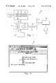
- FIG. 3illustrates a CCMIS utilities window.
- FIG. 4illustrates a Privilege Level Definition window.
- FIG. 5illustrates an Alarm Definition window.
- FIG. 6illustrates an SNMP Community Setup window.
- FIG. 7illustrates an MIB Transfer window.
- Appendix A, B, and C referred to hereafterare included herein as a Microfiche Appendix.
- FIG. 1shows a network 20 having a terminal 22 , a call center management information system (CCMIS) 24 , a management information base (MIB) 25 , a local area network (LAN) connection 26 , a simple network management protocol (SNMP) interface 28 , a network management system (NMS) 30 , a graphic workstation 32 , a plurality of agents 34 , and an automatic call distributor (ACD) switch 36 .
- CCMIScall center management information system
- MIBmanagement information base
- LANlocal area network
- SNMPsimple network management protocol
- NMSnetwork management system
- graphic workstation 32a plurality of agents 34
- ACDautomatic call distributor
- the SNMP interface 28 and the MIB 25are identical to the SNMP interface 28 and the MIB 25.
- SNMPis a standard internetwork protocol (IP) that allows an NMS to gather status information from devices in a network, such as the network 20 .
- IPinternetwork protocol
- These devicestypically include hubs, routers, and bridges.
- the definition of the data made available to the NMS by the devicesis stored in an MIB, such as the MIB 25 .
- the MIB 25defines a set of items that management applications and agents use to report and control managed devices.
- the MIB 25includes a name for identifying the particular MIB.
- the name of the MIB 25is followed by an import statement which allows an MIB writer to specify information from other MIBs that are referred to in the MIB 25 .
- the MIB 25also includes a structure defining a group or groups for organizing related pieces of information.
- a groupmay contain information in the form of items (objects), subgroups, or a combination of the two. Similarly, each sub-group is configured like a group. Within a group or sub-group, data is organized as a scaler item or a table.
- a scalar itemis a single piece of information, for example, the total memory in a server.
- a tableis a structure for organizing several pieces of information, or elements, to uniquely identify a single data item within a group of similar items.
- a tableincludes a SEQUENCE operator, which provides a definition for a table type from a group of several standard types.
- a tablealso includes a SEQUENCE-OF operator, which defines a list having the same type of elements.
- a tablealso includes an INDEX clause, which specifies the items that can be used to uniquely identify an element in the table.
- An example of an item that can be organized in a tableis an EISA board ID.
- Each item defined in the MIB 25includes a description having a SYNTAX, ACCESS, STATUS and DESCRIPTION clause.
- the SYNTAX clausespecifies the type of information which the item contains, such as “integer,” “octet string,” “counter” or “ASCII.”
- the ACCESS clausespecifies how the item may be used and shows the actions which the agent may support for the item, such as “read-only,” “read-write” or “not-accessible.” “Not-accessible” specifies the access for organizational constructs that do not represent data items and is used only for table features and should not be used for a scaler item.
- the STATUS clausespecifies whether the item is required for an agent that supports the defined group, such as “mandatory”, which means that the item will always be present if the defined group is supported by the agent, or “optional,” which means that a particular implementation has the option of supporting the item.
- the DESCRIPTION clausecontains a delimited text description of the item. The item definition ends by specifying how the item fits into the MIB 25 , such as the group to which the item belongs and a unique branch number within the group for the item.
- the MIB 25also contains trap definitions.
- a trapis a notification sent by the SNMP agent 39 to the workstation 32 . The trap is sent to inform a supervisor at the workstation 32 about an event that has occurred.
- a trap definitionbegins with a name of the trap, followed by a term TRAP-TYPE.
- An ENTERPRISE clause, an optional VARIABLES clause, a DESCRIPTION clause, and a numberare then provided by the trap.
- the additional information contained in the ENTERPRISE and VARIABLES clauseswill be items defined in the MIB 25 to identify the trap.
- the DESCRIPTION clauseexplains the significance of the trap and the conditions that would cause it to be sent.
- the numberis unique within the scope of the ENTERPRISE. Both the enterprise name and the trap number are used by the management station to uniquely determine the identity of a received trap.
- the MIB 25is a custom MIB for the CCMIS 24 that describes the variables supported by the SNMP agent 39 .
- a branchmust be made for the MIB in the “private.enterprises” subtree.
- Northern Telecom, Inc.(nt) currently has an official branch number of “562” in this subtree that was assigned by the Internet Assigned Numbers Authority (IANA). Accordingly, all nt SNMP-manageable products are assigned branch numbers under the branch number “562”. Under the “562” branch, the CCMIS is assigned branch number 6.
- the starting point for all custom CCMIS MIBsis as follows:
- the SNMP interface 28can be added to the CCMIS 24 .
- the CCMIS 24supports a standard MIB-2 as well as two custom MIB definitions for management of the CCMIS 24 entity running on this platform.
- the MIB-2includes information regarding the host system and its network interfaces. Requests for MIB-2 variables are passed off by the CCMIS agent to a standard agent for processing.
- the NMS 30queries and retrieves information from the MIB-2 and/or the custom CCMIS MIBs. Based on the retrieved information, the NMS 30 determines the status of the ACD group 36 a.
- CCMISCompute resource
- the CCMIS service provideris responsible for maintaining and configuring the physical CCMIS hardware platform and the associated software.
- the call center operatorsuse CCMIS capabilities and services to manage their ACD call centers. Because of these two classes of users, there is a need to provide a clear delineation between what the service provider and call center operator can access. For this reason two different MIB definitions are created, a CCMIS System MIB and a CCMIS Partition MIB.
- the variables defined in the CCMIS System MIBare designed for use by the CCMIS service provider, while the CCMIS Partition MIB is designed to be used by the call center operator.
- the CCMIS System MIBis a private MIB extension that provides information regarding the state and health of the CCMIS 24 .
- the CCMIS Partition MIBis a private MIB extension that provides status information for a single partition within the CCMIS 24 .
- the definition of the CCMIS Partition MIBis the same for all partitions, the location of the CCMIS Partition MIB within the SNMP object hierarchy is different for each partition. Accordingly, access controls can be defined independently for each partition, thereby keeping the information in each MIB private. Therefore, the MIB 25 provides status information for the partition as well as user-defined information for each ACD group 36 a being monitored by that partition.
- the CCMIS 24which contains the MIB 25 , is coupled to the ACD switch 36 and monitors the status of each of the plurality of agents 34 located at the ACD switch 36 .
- the CCMIS 24is also coupled to the NMS 30 using the SNMP interface 28 .
- the NMS 30queries the CCMIS 24 for status information.
- the NMS 30can monitor, through the CCMIS 24 , the status of each ACD group 36 a .
- the status of any ACD groupviolates an alarm conditions, as discussed in detail below, an alarm is triggered.
- the SNMP agent 39 within the CCMIS 24generates and sends a corresponding trap message 38 to the NMS 30 .
- the possible types of trap messagesare set forth in Table 6 of Appendix A.
- a specific trapis generated, which may be any of those set forth in Table 1 of Appendix A.
- the CCMIS 24When the CCMIS 24 generates the trap message 38 , a corresponding start and end signal are generated to indicate, respectively, the start of the problem condition and the end of the problem condition.
- An interface 40couples the terminal 22 to the CCMIS 24 .
- the interface 40provides a connection to the CCMIS 24 .
- the supervisorcan set and change alarm condition parameters using the terminal 22 .
- the supervisordefines an alarm by establishing alarm condition parameters for monitoring the ACD group 36 a . Accordingly, if the status of any ACD group 36 a within the ACD switch 36 violates the alarm condition, then the CCMIS 24 detects a violation of the alarm conditions. When the alarm condition is violated, a trap signal is triggered and the CCMIS 24 sends the SNMP trap messages 38 to the NMS 30 . Based on the alarm definition, the NMS 30 can determine the condition and the attention required.
- Access to each of the supported MIBsis controlled separately.
- Setup of the SNMP access control for MIB-2 and the CCMIS System MIBis performed via the maintenance interface.
- Access control setup for the CCMIS Partition MIBis via the supervisor interface.
- Access control in the SNMP protocolis via “communities” that consist of a community name, an access mode, and the set of the IP addresses of SNMP managers within that community.
- CCMISwill implement a set of three communities for each MIB made up of the following: a read-only community, a read-write community, and a trap community.
- the read-only communitylists the addresses of query managers or SNMP managers which may query MIB variables, but are not allowed to set them.
- the read-write communitylists the addresses of the SNMP managers that can query as well as set MIB variables.
- the trap communitylists the addresses of the SNMP managers that are to receive any traps generated.
- each communityis configurable and may consist of 1 to 15 characters. Although it is desirable for the read-only and read-write communities to have different names, if the read-only and the read-write communities are named the same, then the IP address of the requesting manager is used to determine which access should be granted to the request, with the read-write community being searched first.
- IP address of 0.0.0.0is entered into the IP address list of a community, then all SNMP managers will be considered to be a part of that community.
- the 0.0.0.0 IP addressmay not be used in the trap community because the CCMIS 24 needs an explicit list of SNMP managers that are to receive traps.
- the CCMIS System MIB definitionconsists of the following groups: BASE, LINKS, and PTNS.
- BASE groupis a group of variables that provide very general information about the CCMIS 24 .
- the variablesare not related to any specific component of the CCMIS system software and are primarily for informational purposes, having read-only type of access.
- the variables and their descriptionsare shown in Table 2 of Appendix A.
- the LINKS groupcontains information and statistics relating to the configuration and status of a link 42 , which can be any conventional link, such as an X.25 link, from the CCMIS 42 to the ACD switch 36 .
- the links groupcontains a table of statistics maintained for each live link to the ACD switch 36 .
- the variables in the LINKS groupare shown in Table 3 of Appendix A.
- the third group in the system MIBis the PTNS group.
- the PTNS groupcontains status information for each of the partitions configured on the CCMIS 24 .
- the PTNS groupprovides partition status information for each partition defined on the CCMIS 24 .
- the PTNS groupis used to monitor the health of the portion of the CCMIS 24 that implements a distinct call center operator environment.
- the variables in the PTNS groupare shown in Table 4 of Appendix A.
- the CCMIS Partition MIBcontains information that is useful to the call center operator.
- the CCMIS Partition MIBhas ACD group variables.
- the ACD group variablescontain information describing the current configuration of the ACD switch 36 and the status of the ACD switch 36 .
- the ACD group variables in the CCMIS Partition MIBprovides the NMS 30 with information to manage and monitor the ACD switch 36 .
- the ACD group variablesare partially customizable by the user in that the statistics provided for each of the ACD group variables can be defined via the terminal 22 .
- the variables in the ACD groupare shown in Table 5 of Appendix A.
- FIG. 3illustrates the menu items for distribution of custom MIB definitions. Transfer or distribution is necessary in order for the NMS 30 to be able to access and use the variables defined in the CCMIS System MIB and CCMIS Partition MIB.
- the MIB definition filesare simple text files written according to the standard syntax defined in Request For Comments (RFC) 115 .
- the MIB definitions filesare compiled or loaded into the database of the NMS 30 .
- RRCRequest For Comments
- two mechanisms for the distribution of the MIB definition filesare used.
- a maintenance interfacesuch as the “maint” Unix log in, is enhanced with an additional menu item 44 in a System Upgrade Utilities menu 46 .
- This interfacefacilitates the transfer of the CCMIS System MIB definition files and/or the CCMIS Partition MIB definition files to any network accessible machine which supports a File Transfer Protocol (FTP).
- FTPFile Transfer Protocol
- the distribution of MIB definition filesis accomplished via the interface 40 .
- This distribution mechanismdownloads the CCMIS System MIB definition file and/or the CCMIS Partition MIB definition files for the partition to which the supervisor interface is connected.
- the SNMP interface 28has a CCMIS Maintenance Interface (not shown) that supports SNMP access to the CCMIS System MIB and provides a mechanism for downloading MIB definition files to the NMS 30 .
- CCMIS Maintenance InterfaceIn order for the CCMIS Maintenance Interface to support the SNMP access, the following areas are changed: (1) Configuration Utility; (2) SNMP Configuration Report; and (3) MIB Transfer Utility.
- the community namesare defaulted to “public”, “secure”, and “traps” for the read-only, read-write, and traps communities, respectively.
- the members list for the read-only communityis set to 0.0.0.0, while the other two member lists are empty.
- Each community name stringmay contain any string of characters, between 1 and 15 characters in length.
- any community name stringis completely empty, the community definitions can not be saved.
- the members listswill accept any syntactically valid IP addresses, including 0.0.0.0, in either of the read-only or read-write community definitions.
- the 0.0.0.0 IP addressis not allowed in the trap community.
- the 0.0.0.0 IP addresscan be used to allow any SNMP operator access to the MIB variables provided the proper community name is used.
- FIG. 4illustrates a Privilege Level Definition window 48 used to control access to the alarm definition and SNMP setup screens by adding an alarms privilege option to the Displays group in each privilege level definition.
- the alarms/SNMP functionalityis associated with the Displays menu since the alarm statistics are based on the same statistics as the real-time displays.
- Each alarm definitioncontains variables that identify the source and type of problem using the following variable: OBJECT, SYNTAX, ACCESS, or DESCRIPTION.
- OBJECTdefines a symbolic name and an object ID relative to a branch of the MIB 25 being described.
- an object-instance IDIn order for the NMS 30 to query the value of a particular object, an object-instance ID must be formed from the object ID presented in the MIB definitions.
- the object-instance IDis the variable's object ID with a zero (0.0) concatenated.
- the object-instance ID for any particular cell in the tableis the object ID of the variable with the values of all index variables for that row of the table tacked on to the end.
- index variable valuesare concatenated in the order in which they appear in the MIB definition.
- SYNTAXis used to define the type of the object to the NMS 30 .
- ACCESSdefines the accessibility of the object.
- DESCRIPTIONis a description of the purpose of the value.
- FIG. 5illustrates an Alarm Definition window 50 when the user selects the Displays/Alarms command from the main menu.
- the Alarm Definition window 50allows up to one hundred custom statistics to be monitored for each ACD group 36 a , FIG. 1, in the partition.
- the setup of each statisticincludes threshold and alarm information.
- the information defined for each Alarm Definitionis supplied to the NMS 30 when the NMS 30 queries the entries in the CCMIS Partition MIB. Although the NMS 30 cannot add or delete entries, it can modify some of the fields in existing table entries. Thus, once the Alarm Definitions have been defined, they can be maintained either via the Alarm Definition window 50 or via the NMS 30 .
- the Alarm Definition window 50includes four major components; a tool bar 52 , a status bar 54 , a form template 56 , and a definitions list 58 .
- the tool bar 52is the row of buttons across the top of the window which provides shortcuts to many of the commands available on the window's menu.
- a standard Windows 95 tool-tip windowsas provided by Microsoft Corp. of Redmond, Wash., can be provided for the tool bar 52 .
- the status bar 54appears at the bottom of the window and consists of three sections: a first section 54 a indicates the number of records defined and the maximum number allowed; a second section 54 b indicates the number of records currently selected in the definitions list; and a third section 54 c is for displaying status and progress messages.
- the form template 56consists of fields used to enter and modify the alarm definition.
- the form template 56has an alarm ID field 56 a , an alarm name field 56 b , a formula field 56 c , a threshold level filed 56 d , a plus field 56 e , a threshold type field 56 f , an alarm type field 56 g , an alarm delay field 56 h , and an alarm groups field 56 i.
- the alarm ID field 56 acontains a unique number in the range 1 to 100 and has an SNMP object ID.
- the SNMP object IDcould be acdAlarmDefnIndex and designated as read-only.
- the value of the alarm ID field 56 ais used as the object instance ID used by the NMS 30 to access a particular entry in the table, such as the acdAlarmDefh Table.
- the alarm name field 56 bcontains the name assigned to the alarm ID field 56 a for a unique alarm condition.
- the alarm name field 56 bcan hold up to 30 characters excluding the vertical bar character (
- the alarm name field 56 bhas an SNMP object ID.
- the SNMP object IDcould be acdAlarmDefnName and designated as read-only.
- the formula field 56 chas either the standard or custom formula used to compute the statistic value upon which the alarm definition for the alarm condition is based.
- the formula field 56does not have an SNMP object ID.
- the threshold level field 56 ddetermines whether the computed value for the statistic should cause an alarm condition to be triggered.
- the threshold level field 56 dcan have one of two values. Two possible values are BELOW or ABOVE. In this example, if the ABOVE value is selected, then the alarm condition is triggered when the statistic value begins to exceed the threshold value and ends when the statistic value falls below the threshold value. If the BELOW value is selected, then the alarm condition is triggered when the statistic value falls below the threshold value and ends when the statistic value rises back above the threshold value.
- the threshold level field 56 dhas an SNMP object ID. For example, the threshold level field 56 d is accessible as the read-write SNMP object ID “acdAlarmDefnThrDir” within the acdAlarmDefn table.
- the plus field 56 econtains a constant component, which defines a numeric value to be added to the value of the threshold level field 56 d to arrive at the threshold value used for determining when the statistic value indicates an alarm state.
- the plus field 56 ecan be any signed 32-bit number ( ⁇ 2,147,483,647 through 2,147,483,647).
- the plus fieldhas an SNMP object ID.
- the SNMP object IDcould be acdAlarmDefnThrConst and designated as read-write.
- the threshold type field 56 fcontains a threshold type.
- the threshold type in the threshold type field 56 fis applied to the statistic value and can be any of the available ACD group thresholds or a special threshold type, such as zero, where the threshold value is defined solely by the constant value entered in the plus field 56 e .
- the threshold type field 56 fhas an SNMP object ID.
- the SNMP object IDcould be acdAlarmDefnThrType and designated as read-write.
- the alarm type field 56 gdetermines the type of alarm or SNMP trap to be generated.
- the alarm type field 56 gcan be set to a POLL, a MINOR, a MAJOR, or a CRITICAL setting.
- the POLL settingdesignates that no trap is generated and the NMS 30 must periodically poll the CCMIS 24 to get the statistic value. If either of the MINOR, MAJOR, or CRITICAL settings are selected then a trap is generated.
- the alarm type field 56 ghas an SNMP object ID.
- the SNMP object IDcould be acdAlarmDefnAlarmType and designated as read-write.
- the alarm delay field 56 hsets a delay period, in seconds, from the time that the alarm condition is first detected until the time that an SNMP trap is sent. If the alarm condition clears within the delay period, then no trap is sent. Furthermore, the delay value also applies to clearing an alarm condition, with a maximum delay value of 999 seconds.
- the alarm delay field 56 hhas an SNMP object ID.
- the SNMP object IDcould be acdAlarmDefnAlarmDelay and designated as read-write.
- the alarm groups field 56 idetermines which ACD group should cause traps to be generated.
- the alarm groups field 56 icontains the names of all currently defined ACD group lists and the special ALL selection. When one list is selected only the groups in the list will cause traps to be generated. If ALL is selected, then all ACD groups can cause traps to be generated.
- the alarm groups field 56 idoes not have an SNMP object ID.
- the definitions list 58is located in the bottom half of the screen and displays a scrollable list of currently defined alarm definitions.
- the Alarm Definition window 50is resizable so that the number of definitions displayed in the alarm definition list 58 can be adjusted by the user. Any or all of the fields in the definition may be displayed as a column in the definitions list. The only restriction is that an ID column 58 a must always appear as the first column. As columns are added or removed, the columns will automatically resize themselves to provide a best fit for the current width of the window.
- the operation of the Alarm Definition window 50depends on the current mode as indicated by a label in a mode button 60 .
- MODIFY modeentering the alarm ID of an existing alarm definition record in the alarm ID field 56 a , or selecting a record in the alarm definitions list, causes the selected record to be read into the form so that it can be changed.
- the same changecan be made to one or more fields of all selected records.
- the background color of each fieldwill indicate whether or not it contains changes. The new values shown in the modified fields replace the current value of the fields for all selected records. If a record is selected in the definitions list while the mode button 60 indicates ADD, then the mode is automatically switched to MODIFY and the selected record is loaded into the template fields.
- FIG. 6illustrates an SNMP Community Setup window 70 , which is accessed from the Alarm Definition window 50 .
- the SNMP Community Setup window 70allows the user to define the access rights for various NMSs, such as the NMS 30 , wishing to access the CCMIS Partition MIB.
- the SNMP Community Setup window 70displays the current settings for each of the three communities defined by the CCMIS 24 .
- the community namesare defaulted to “public”, “secure”, and “traps” for a read-only community 72 , a read-write community 74 , and a trap community 76 , respectively.
- the members list for the read-only communitywill be set to 0.0.0.0, while the other two members lists will be empty.
- Each community name stringcan be any string of characters, between 1 and 15 characters in length, from the set of all characters excluding the vertical bar character (
- the members listswill accept any syntactically valid IP addresses, including 0.0.0.0 in either of the read-only or read-write community definitions.
- the 0.0.0.0 IP addresswill not be allowed in the trap community.
- the 0.0.0.0 IP addresscan be used allow any SNMP manager to access the MIB variables provided the proper community name is used. A limit of 100 IP addresses will be allowed in each of the members lists.
- FIG. 7illustrates an MIB Transfer window 80 that is accessed from the Alarm Definition window 50 .
- the MIB transfer window 80allows the user to download the CCMIS MIB definition files to a local PC for use with the NMS 30 .
- the MIB definition filesare text files which define all of the SNMP objects implemented by the CCMIS 24 .
- the MIB filesare written using the conventions described in RFCs 1155 and 1215 and are loaded or compiled into any SNMP-compliant NMS without modification. Note that the CCMIS Partition MIB definition file is set up to access the partition from which the MIB file was downloaded.
- the MIB Transfer window 80allows the user to select either the CCMIS Partition MIB or the CCMIS System MIB to be downloaded.
- limit and control access to the alarm definition and configuration of the SNMPis achieved by using a privilege flag added to a Privilege Level Definition mode.
- the LAN connection 26 of the network 20is replaced by a wide area network (WAN) connection without deviation from the scope of the present invention.
- WANwide area network
Landscapes
- Business, Economics & Management (AREA)
- Marketing (AREA)
- Engineering & Computer Science (AREA)
- Signal Processing (AREA)
- Data Exchanges In Wide-Area Networks (AREA)
Abstract
Description
Claims (22)
Priority Applications (1)
| Application Number | Priority Date | Filing Date | Title |
|---|---|---|---|
| US08/998,323US6181776B1 (en) | 1997-12-24 | 1997-12-24 | Network management of automatic call distributor resources |
Applications Claiming Priority (1)
| Application Number | Priority Date | Filing Date | Title |
|---|---|---|---|
| US08/998,323US6181776B1 (en) | 1997-12-24 | 1997-12-24 | Network management of automatic call distributor resources |
Publications (1)
| Publication Number | Publication Date |
|---|---|
| US6181776B1true US6181776B1 (en) | 2001-01-30 |
Family
ID=25545056
Family Applications (1)
| Application Number | Title | Priority Date | Filing Date |
|---|---|---|---|
| US08/998,323Expired - LifetimeUS6181776B1 (en) | 1997-12-24 | 1997-12-24 | Network management of automatic call distributor resources |
Country Status (1)
| Country | Link |
|---|---|
| US (1) | US6181776B1 (en) |
Cited By (32)
| Publication number | Priority date | Publication date | Assignee | Title |
|---|---|---|---|---|
| US6292472B1 (en)* | 1998-10-22 | 2001-09-18 | Alcatel | Reduced polling in an SNMPv1-managed network |
| EP1209887A3 (en)* | 2000-11-27 | 2002-07-03 | Avaya, Inc. | Arrangement for using dynamic metrics to monitor contact center performance |
| US20020120765A1 (en)* | 2000-12-22 | 2002-08-29 | Bellsouth Intellectual Property Corporation | System, method and apparatus for obtaining real-time information associated with a telecommunication network |
| US20020119786A1 (en)* | 2000-12-22 | 2002-08-29 | Yuergen Boehmke | System, apparatus and method for managing telephone call records |
| US20020119771A1 (en)* | 2000-12-22 | 2002-08-29 | Bellsouth Intellectual Property Corporation | System, method and apparatus for capturing and processing call processing failures occurring at a digital wireless switch |
| US6446123B1 (en)* | 1999-03-31 | 2002-09-03 | Nortel Networks Limited | Tool for monitoring health of networks |
| US20020126822A1 (en)* | 2000-12-22 | 2002-09-12 | Yuergen Boehmke | System, method and apparatus for capturing and processing call processing failures occurring at a telephone switch control processor |
| US20020141561A1 (en)* | 2000-04-12 | 2002-10-03 | Austin Logistics Incorporated | Method and system for self-service scheduling of inbound inquiries |
| US20030016812A1 (en)* | 2001-07-09 | 2003-01-23 | Austin Logistics Incorporated | System and method for preemptive goals based routing of contact records |
| US20030105861A1 (en)* | 2001-12-04 | 2003-06-05 | Jong-Ky Lee | System and method for managing and displaying representative severity of network element in SNMP |
| EP1326412A1 (en)* | 2002-01-03 | 2003-07-09 | Avaya Technology Corp. | Uninterrupted automatic call distribution during failure and recovery of computer-telephony integration |
| US20030198336A1 (en)* | 2001-07-09 | 2003-10-23 | Richard Rodenbusch | System and method for common account based routing of contact records |
| US6772207B1 (en)* | 1999-01-28 | 2004-08-03 | Brocade Communications Systems, Inc. | System and method for managing fibre channel switching devices |
| US20040162810A1 (en)* | 2003-02-14 | 2004-08-19 | Eung-Sun Jeon | Database table modeling and event handling method for real time alarm management |
| US20040179672A1 (en)* | 2001-07-09 | 2004-09-16 | Austin Logistics Incorporated | System and method for updating contact records |
| US6832247B1 (en)* | 1998-06-15 | 2004-12-14 | Hewlett-Packard Development Company, L.P. | Method and apparatus for automatic monitoring of simple network management protocol manageable devices |
| US20050049995A1 (en)* | 2003-08-22 | 2005-03-03 | Ora International, Inc. | system and method for providing and updating information via a browser |
| US20060149852A1 (en)* | 2003-01-28 | 2006-07-06 | Gero Schollmeier | Allocation of distribution weights to links in a packet network comprising traffic distribution |
| US20060146784A1 (en)* | 2001-11-16 | 2006-07-06 | Ibasis, Inc. | System and method for monitoring a voice over internet protocol (VoIP) system |
| US7099660B2 (en) | 2000-12-22 | 2006-08-29 | Bellsouth Intellectual Property Corp. | System, method and apparatus for a network-organized repository of data |
| US20060215833A1 (en)* | 2005-03-22 | 2006-09-28 | Sbc Knowledge Ventures, L.P. | System and method for automating customer relations in a communications environment |
| US20060233347A1 (en)* | 2005-04-19 | 2006-10-19 | Cisco Technology, Inc. | Method and system for automatic supervisor intervention in problematic calls in a call center |
| US7142662B2 (en) | 2000-07-11 | 2006-11-28 | Austin Logistics Incorporated | Method and system for distributing outbound telephone calls |
| US20070047532A1 (en)* | 2005-08-29 | 2007-03-01 | Sbc Knowledge Ventures, L.P. | System and method of managing telephone calls within a voice over internet protocol telephone system |
| US7502460B2 (en) | 2006-11-20 | 2009-03-10 | Austin Logistics Incorporated | Method and system for distributing outbound telephone calls |
| US7797634B2 (en) | 2002-10-31 | 2010-09-14 | Brocade Communications Systems, Inc. | Method and apparatus for displaying network fabric data |
| US20110138291A1 (en)* | 2009-12-08 | 2011-06-09 | Robert Twiddy | Configurable network management system event processing using simple network management table indices |
| US8751232B2 (en) | 2004-08-12 | 2014-06-10 | At&T Intellectual Property I, L.P. | System and method for targeted tuning of a speech recognition system |
| US8824659B2 (en) | 2005-01-10 | 2014-09-02 | At&T Intellectual Property I, L.P. | System and method for speech-enabled call routing |
| US9031222B2 (en) | 2011-08-09 | 2015-05-12 | Cisco Technology, Inc. | Automatic supervisor intervention for calls in call center based upon video and/or speech analytics of calls |
| US9112972B2 (en) | 2004-12-06 | 2015-08-18 | Interactions Llc | System and method for processing speech |
| CN107231493A (en)* | 2017-06-30 | 2017-10-03 | 携程旅游信息技术(上海)有限公司 | Automatic alarm method and its device, storage medium, the electronic equipment of call center |
Citations (7)
| Publication number | Priority date | Publication date | Assignee | Title |
|---|---|---|---|---|
| US5299259A (en)* | 1991-09-27 | 1994-03-29 | At&T Bell Laboratories | Distributing calls over serving centers of a large customer |
| US5325292A (en)* | 1990-10-12 | 1994-06-28 | Crockett Gary B | Tour/schedule generation for a force management system |
| US5802146A (en)* | 1995-11-22 | 1998-09-01 | Bell Atlantic Network Services, Inc. | Maintenance operations console for an advanced intelligent network |
| US5911134A (en)* | 1990-10-12 | 1999-06-08 | Iex Corporation | Method for planning, scheduling and managing personnel |
| US5946375A (en)* | 1993-09-22 | 1999-08-31 | Teknekron Infoswitch Corporation | Method and system for monitoring call center service representatives |
| US5968124A (en)* | 1996-05-08 | 1999-10-19 | Fujitsu Limited | Network operation managing system, method and computer program product |
| US6115393A (en)* | 1991-04-12 | 2000-09-05 | Concord Communications, Inc. | Network monitoring |
- 1997
- 1997-12-24USUS08/998,323patent/US6181776B1/ennot_activeExpired - Lifetime
Patent Citations (7)
| Publication number | Priority date | Publication date | Assignee | Title |
|---|---|---|---|---|
| US5325292A (en)* | 1990-10-12 | 1994-06-28 | Crockett Gary B | Tour/schedule generation for a force management system |
| US5911134A (en)* | 1990-10-12 | 1999-06-08 | Iex Corporation | Method for planning, scheduling and managing personnel |
| US6115393A (en)* | 1991-04-12 | 2000-09-05 | Concord Communications, Inc. | Network monitoring |
| US5299259A (en)* | 1991-09-27 | 1994-03-29 | At&T Bell Laboratories | Distributing calls over serving centers of a large customer |
| US5946375A (en)* | 1993-09-22 | 1999-08-31 | Teknekron Infoswitch Corporation | Method and system for monitoring call center service representatives |
| US5802146A (en)* | 1995-11-22 | 1998-09-01 | Bell Atlantic Network Services, Inc. | Maintenance operations console for an advanced intelligent network |
| US5968124A (en)* | 1996-05-08 | 1999-10-19 | Fujitsu Limited | Network operation managing system, method and computer program product |
Cited By (61)
| Publication number | Priority date | Publication date | Assignee | Title |
|---|---|---|---|---|
| US6832247B1 (en)* | 1998-06-15 | 2004-12-14 | Hewlett-Packard Development Company, L.P. | Method and apparatus for automatic monitoring of simple network management protocol manageable devices |
| US6292472B1 (en)* | 1998-10-22 | 2001-09-18 | Alcatel | Reduced polling in an SNMPv1-managed network |
| US6772207B1 (en)* | 1999-01-28 | 2004-08-03 | Brocade Communications Systems, Inc. | System and method for managing fibre channel switching devices |
| US6446123B1 (en)* | 1999-03-31 | 2002-09-03 | Nortel Networks Limited | Tool for monitoring health of networks |
| US20020141561A1 (en)* | 2000-04-12 | 2002-10-03 | Austin Logistics Incorporated | Method and system for self-service scheduling of inbound inquiries |
| US6859529B2 (en) | 2000-04-12 | 2005-02-22 | Austin Logistics Incorporated | Method and system for self-service scheduling of inbound inquiries |
| USRE46420E1 (en) | 2000-07-11 | 2017-05-30 | Noble Systems Corporation | Method and system for distributing outbound telephone calls |
| USRE46478E1 (en) | 2000-07-11 | 2017-07-11 | Noble Systems Corporation | System and method for preemptive goals based routing of contact records |
| USRE46467E1 (en) | 2000-07-11 | 2017-07-04 | Noble Systems Corporation | Method and system for distributing outbound telephone calls |
| US7239692B2 (en) | 2000-07-11 | 2007-07-03 | Austin Logistics Incorporated | Method and system for distributing outbound telephone calls |
| US20070121900A1 (en)* | 2000-07-11 | 2007-05-31 | Richard Rodenbusch | Method and System for Distributing Outbound Telephone Calls |
| US7142662B2 (en) | 2000-07-11 | 2006-11-28 | Austin Logistics Incorporated | Method and system for distributing outbound telephone calls |
| EP1209887A3 (en)* | 2000-11-27 | 2002-07-03 | Avaya, Inc. | Arrangement for using dynamic metrics to monitor contact center performance |
| US6700971B1 (en) | 2000-11-27 | 2004-03-02 | Avaya Technology Corp. | Arrangement for using dynamic metrics to monitor contact center performance |
| US7080144B2 (en) | 2000-12-22 | 2006-07-18 | Bell South Intellectual Property Corp. | System enabling access to obtain real-time information from a cell site when an emergency event occurs at the site |
| US20020119771A1 (en)* | 2000-12-22 | 2002-08-29 | Bellsouth Intellectual Property Corporation | System, method and apparatus for capturing and processing call processing failures occurring at a digital wireless switch |
| US6788933B2 (en)* | 2000-12-22 | 2004-09-07 | Bellsouth Intellectual Property Corporation | System, method and apparatus for capturing and processing call processing failures occurring at a digital wireless switch |
| US7099660B2 (en) | 2000-12-22 | 2006-08-29 | Bellsouth Intellectual Property Corp. | System, method and apparatus for a network-organized repository of data |
| US20020119786A1 (en)* | 2000-12-22 | 2002-08-29 | Yuergen Boehmke | System, apparatus and method for managing telephone call records |
| US20020120765A1 (en)* | 2000-12-22 | 2002-08-29 | Bellsouth Intellectual Property Corporation | System, method and apparatus for obtaining real-time information associated with a telecommunication network |
| US7295829B2 (en) | 2000-12-22 | 2007-11-13 | At&T Bls Intellectual Property, Inc. | System, apparatus and method for managing telephone call records |
| US20020126822A1 (en)* | 2000-12-22 | 2002-09-12 | Yuergen Boehmke | System, method and apparatus for capturing and processing call processing failures occurring at a telephone switch control processor |
| US7054434B2 (en) | 2001-07-09 | 2006-05-30 | Austin Logistics Incorporated | System and method for common account based routing of contact records |
| USRE44979E1 (en) | 2001-07-09 | 2014-07-01 | Noble Systems Corporation | System and method for common account based routing of contact records |
| US20030016812A1 (en)* | 2001-07-09 | 2003-01-23 | Austin Logistics Incorporated | System and method for preemptive goals based routing of contact records |
| US20040179672A1 (en)* | 2001-07-09 | 2004-09-16 | Austin Logistics Incorporated | System and method for updating contact records |
| US7103173B2 (en) | 2001-07-09 | 2006-09-05 | Austin Logistics Incorporated | System and method for preemptive goals based routing of contact records |
| US7715546B2 (en) | 2001-07-09 | 2010-05-11 | Austin Logistics Incorporated | System and method for updating contact records |
| US20060222165A1 (en)* | 2001-07-09 | 2006-10-05 | Richard Rodenbusch | System and method for preemptive goals based routing of contact records |
| US8175258B2 (en) | 2001-07-09 | 2012-05-08 | Austin Logistics Incorporated | System and method for common account based routing of contact records |
| US7158629B2 (en) | 2001-07-09 | 2007-01-02 | Austin Logistics Incorporated | System and method for preemptive goals based routing of contact records |
| US20030198336A1 (en)* | 2001-07-09 | 2003-10-23 | Richard Rodenbusch | System and method for common account based routing of contact records |
| US20060146784A1 (en)* | 2001-11-16 | 2006-07-06 | Ibasis, Inc. | System and method for monitoring a voice over internet protocol (VoIP) system |
| US20030105861A1 (en)* | 2001-12-04 | 2003-06-05 | Jong-Ky Lee | System and method for managing and displaying representative severity of network element in SNMP |
| US6748073B2 (en) | 2002-01-03 | 2004-06-08 | Avaya Technology Corp. | Uninterrupted automatic call distribution during failure and recovery of computer-telephony integration |
| EP1326412A1 (en)* | 2002-01-03 | 2003-07-09 | Avaya Technology Corp. | Uninterrupted automatic call distribution during failure and recovery of computer-telephony integration |
| US7797634B2 (en) | 2002-10-31 | 2010-09-14 | Brocade Communications Systems, Inc. | Method and apparatus for displaying network fabric data |
| US20060149852A1 (en)* | 2003-01-28 | 2006-07-06 | Gero Schollmeier | Allocation of distribution weights to links in a packet network comprising traffic distribution |
| US7136864B2 (en) | 2003-02-14 | 2006-11-14 | Samsung Electronics Co., Ltd. | Database table modeling and event handling method for real time alarm management |
| US20040162810A1 (en)* | 2003-02-14 | 2004-08-19 | Eung-Sun Jeon | Database table modeling and event handling method for real time alarm management |
| US7277895B2 (en)* | 2003-08-22 | 2007-10-02 | Ora International, Inc. | System and method of parsing a template for generating presentation data |
| US20050049995A1 (en)* | 2003-08-22 | 2005-03-03 | Ora International, Inc. | system and method for providing and updating information via a browser |
| US8751232B2 (en) | 2004-08-12 | 2014-06-10 | At&T Intellectual Property I, L.P. | System and method for targeted tuning of a speech recognition system |
| US9368111B2 (en) | 2004-08-12 | 2016-06-14 | Interactions Llc | System and method for targeted tuning of a speech recognition system |
| US9350862B2 (en) | 2004-12-06 | 2016-05-24 | Interactions Llc | System and method for processing speech |
| US9112972B2 (en) | 2004-12-06 | 2015-08-18 | Interactions Llc | System and method for processing speech |
| US8824659B2 (en) | 2005-01-10 | 2014-09-02 | At&T Intellectual Property I, L.P. | System and method for speech-enabled call routing |
| US9088652B2 (en) | 2005-01-10 | 2015-07-21 | At&T Intellectual Property I, L.P. | System and method for speech-enabled call routing |
| US8488770B2 (en) | 2005-03-22 | 2013-07-16 | At&T Intellectual Property I, L.P. | System and method for automating customer relations in a communications environment |
| US20060215833A1 (en)* | 2005-03-22 | 2006-09-28 | Sbc Knowledge Ventures, L.P. | System and method for automating customer relations in a communications environment |
| US8223954B2 (en)* | 2005-03-22 | 2012-07-17 | At&T Intellectual Property I, L.P. | System and method for automating customer relations in a communications environment |
| US20060233347A1 (en)* | 2005-04-19 | 2006-10-19 | Cisco Technology, Inc. | Method and system for automatic supervisor intervention in problematic calls in a call center |
| US8126136B2 (en)* | 2005-04-19 | 2012-02-28 | Cisco Technology, Inc. | Method and system for automatic supervisor intervention in problematic calls in a call center |
| US8081747B2 (en)* | 2005-08-29 | 2011-12-20 | At&T Intellectual Property I, Lp | System and method of managing telephone calls within a voice over internet protocol telephone system |
| US20070047532A1 (en)* | 2005-08-29 | 2007-03-01 | Sbc Knowledge Ventures, L.P. | System and method of managing telephone calls within a voice over internet protocol telephone system |
| US7502460B2 (en) | 2006-11-20 | 2009-03-10 | Austin Logistics Incorporated | Method and system for distributing outbound telephone calls |
| US9602336B2 (en) | 2009-12-08 | 2017-03-21 | Cisco Technology, Inc. | Configurable network management system event processing using simple network management table indices |
| US9059895B2 (en)* | 2009-12-08 | 2015-06-16 | Cisco Technology, Inc. | Configurable network management system event processing using simple network management table indices |
| US20110138291A1 (en)* | 2009-12-08 | 2011-06-09 | Robert Twiddy | Configurable network management system event processing using simple network management table indices |
| US9031222B2 (en) | 2011-08-09 | 2015-05-12 | Cisco Technology, Inc. | Automatic supervisor intervention for calls in call center based upon video and/or speech analytics of calls |
| CN107231493A (en)* | 2017-06-30 | 2017-10-03 | 携程旅游信息技术(上海)有限公司 | Automatic alarm method and its device, storage medium, the electronic equipment of call center |
Similar Documents
| Publication | Publication Date | Title |
|---|---|---|
| US6181776B1 (en) | Network management of automatic call distributor resources | |
| US7143152B1 (en) | Graphical user interface and method for customer centric network management | |
| US6356282B2 (en) | Alarm manager system for distributed network management system | |
| US6816576B2 (en) | Tree hierarchy and description for generated logs | |
| CA2345117A1 (en) | Interface system for integrated monitoring and management of network devices in a telecommunications network | |
| GB2395858A (en) | Network interface management system | |
| Cisco | Network Topology | |
| Cisco | Using the MIB | |
| Cisco | Using the MIB | |
| Cisco | Using the MIB | |
| Cisco | Using the MIB | |
| Cisco | Using the MIB | |
| Cisco | Using the MIB | |
| Cisco | Using the MIB | |
| Cisco | Using the MIB | |
| Cisco | Using the MIB | |
| Cisco | Using the MIB | |
| Cisco | Using the MIB | |
| Cisco | Using the MIB | |
| Cisco | Using the MIB | |
| Cisco | Using the MIB | |
| Cisco | Using the MIB | |
| Cisco | Using the MIB | |
| Cisco | Using the MIB | |
| Cisco | Using the MIB |
Legal Events
| Date | Code | Title | Description |
|---|---|---|---|
| AS | Assignment | Owner name:NORTHERN TELECOM LIMITED, CANADA Free format text:ASSIGNMENT OF ASSIGNORS INTEREST;ASSIGNORS:CROSSLEY, STEVEN JOHN;RAMBO, MICHAEL DEAN;REEL/FRAME:008945/0631 Effective date:19971219 | |
| AS | Assignment | Owner name:NORTEL NETWORKS CORPORATION, CANADA Free format text:CHANGE OF NAME;ASSIGNOR:NORTHERN TELECOM LIMITED;REEL/FRAME:010567/0001 Effective date:19990429 | |
| AS | Assignment | Owner name:NORTEL NETWORKS LIMITED, CANADA Free format text:CHANGE OF NAME;ASSIGNOR:NORTEL NETWORKS CORPORATION;REEL/FRAME:011195/0706 Effective date:20000830 Owner name:NORTEL NETWORKS LIMITED,CANADA Free format text:CHANGE OF NAME;ASSIGNOR:NORTEL NETWORKS CORPORATION;REEL/FRAME:011195/0706 Effective date:20000830 | |
| FEPP | Fee payment procedure | Free format text:PAYOR NUMBER ASSIGNED (ORIGINAL EVENT CODE: ASPN); ENTITY STATUS OF PATENT OWNER: LARGE ENTITY | |
| STCF | Information on status: patent grant | Free format text:PATENTED CASE | |
| FEPP | Fee payment procedure | Free format text:PAYOR NUMBER ASSIGNED (ORIGINAL EVENT CODE: ASPN); ENTITY STATUS OF PATENT OWNER: LARGE ENTITY Free format text:PAYER NUMBER DE-ASSIGNED (ORIGINAL EVENT CODE: RMPN); ENTITY STATUS OF PATENT OWNER: LARGE ENTITY | |
| FPAY | Fee payment | Year of fee payment:4 | |
| FEPP | Fee payment procedure | Free format text:PAYOR NUMBER ASSIGNED (ORIGINAL EVENT CODE: ASPN); ENTITY STATUS OF PATENT OWNER: LARGE ENTITY Free format text:PAYER NUMBER DE-ASSIGNED (ORIGINAL EVENT CODE: RMPN); ENTITY STATUS OF PATENT OWNER: LARGE ENTITY | |
| FPAY | Fee payment | Year of fee payment:8 | |
| FEPP | Fee payment procedure | Free format text:PAYOR NUMBER ASSIGNED (ORIGINAL EVENT CODE: ASPN); ENTITY STATUS OF PATENT OWNER: LARGE ENTITY Free format text:PAYER NUMBER DE-ASSIGNED (ORIGINAL EVENT CODE: RMPN); ENTITY STATUS OF PATENT OWNER: LARGE ENTITY | |
| AS | Assignment | Owner name:CITIBANK, N.A., AS ADMINISTRATIVE AGENT,NEW YORK Free format text:SECURITY AGREEMENT;ASSIGNOR:AVAYA INC.;REEL/FRAME:023892/0500 Effective date:20100129 Owner name:CITIBANK, N.A., AS ADMINISTRATIVE AGENT, NEW YORK Free format text:SECURITY AGREEMENT;ASSIGNOR:AVAYA INC.;REEL/FRAME:023892/0500 Effective date:20100129 | |
| AS | Assignment | Owner name:CITICORP USA, INC., AS ADMINISTRATIVE AGENT, NEW YORK Free format text:SECURITY AGREEMENT;ASSIGNOR:AVAYA INC.;REEL/FRAME:023905/0001 Effective date:20100129 Owner name:CITICORP USA, INC., AS ADMINISTRATIVE AGENT,NEW YO Free format text:SECURITY AGREEMENT;ASSIGNOR:AVAYA INC.;REEL/FRAME:023905/0001 Effective date:20100129 Owner name:CITICORP USA, INC., AS ADMINISTRATIVE AGENT, NEW Y Free format text:SECURITY AGREEMENT;ASSIGNOR:AVAYA INC.;REEL/FRAME:023905/0001 Effective date:20100129 | |
| AS | Assignment | Owner name:AVAYA INC.,NEW JERSEY Free format text:ASSIGNMENT OF ASSIGNORS INTEREST;ASSIGNOR:NORTEL NETWORKS LIMITED;REEL/FRAME:023998/0878 Effective date:20091218 Owner name:AVAYA INC., NEW JERSEY Free format text:ASSIGNMENT OF ASSIGNORS INTEREST;ASSIGNOR:NORTEL NETWORKS LIMITED;REEL/FRAME:023998/0878 Effective date:20091218 | |
| FPAY | Fee payment | Year of fee payment:12 | |
| AS | Assignment | Owner name:CITIBANK, N.A., AS ADMINISTRATIVE AGENT, NEW YORK Free format text:SECURITY INTEREST;ASSIGNORS:AVAYA INC.;AVAYA INTEGRATED CABINET SOLUTIONS INC.;OCTEL COMMUNICATIONS CORPORATION;AND OTHERS;REEL/FRAME:041576/0001 Effective date:20170124 | |
| AS | Assignment | Owner name:AVAYA INTEGRATED CABINET SOLUTIONS INC., CALIFORNIA Free format text:BANKRUPTCY COURT ORDER RELEASING ALL LIENS INCLUDING THE SECURITY INTEREST RECORDED AT REEL/FRAME 041576/0001;ASSIGNOR:CITIBANK, N.A.;REEL/FRAME:044893/0531 Effective date:20171128 Owner name:OCTEL COMMUNICATIONS LLC (FORMERLY KNOWN AS OCTEL COMMUNICATIONS CORPORATION), CALIFORNIA Free format text:BANKRUPTCY COURT ORDER RELEASING ALL LIENS INCLUDING THE SECURITY INTEREST RECORDED AT REEL/FRAME 041576/0001;ASSIGNOR:CITIBANK, N.A.;REEL/FRAME:044893/0531 Effective date:20171128 Owner name:AVAYA INC., CALIFORNIA Free format text:BANKRUPTCY COURT ORDER RELEASING ALL LIENS INCLUDING THE SECURITY INTEREST RECORDED AT REEL/FRAME 023892/0500;ASSIGNOR:CITIBANK, N.A.;REEL/FRAME:044891/0564 Effective date:20171128 Owner name:AVAYA INTEGRATED CABINET SOLUTIONS INC., CALIFORNI Free format text:BANKRUPTCY COURT ORDER RELEASING ALL LIENS INCLUDING THE SECURITY INTEREST RECORDED AT REEL/FRAME 041576/0001;ASSIGNOR:CITIBANK, N.A.;REEL/FRAME:044893/0531 Effective date:20171128 Owner name:OCTEL COMMUNICATIONS LLC (FORMERLY KNOWN AS OCTEL Free format text:BANKRUPTCY COURT ORDER RELEASING ALL LIENS INCLUDING THE SECURITY INTEREST RECORDED AT REEL/FRAME 041576/0001;ASSIGNOR:CITIBANK, N.A.;REEL/FRAME:044893/0531 Effective date:20171128 Owner name:VPNET TECHNOLOGIES, INC., CALIFORNIA Free format text:BANKRUPTCY COURT ORDER RELEASING ALL LIENS INCLUDING THE SECURITY INTEREST RECORDED AT REEL/FRAME 041576/0001;ASSIGNOR:CITIBANK, N.A.;REEL/FRAME:044893/0531 Effective date:20171128 Owner name:AVAYA INC., CALIFORNIA Free format text:BANKRUPTCY COURT ORDER RELEASING ALL LIENS INCLUDING THE SECURITY INTEREST RECORDED AT REEL/FRAME 041576/0001;ASSIGNOR:CITIBANK, N.A.;REEL/FRAME:044893/0531 Effective date:20171128 | |
| AS | Assignment | Owner name:GOLDMAN SACHS BANK USA, AS COLLATERAL AGENT, NEW YORK Free format text:SECURITY INTEREST;ASSIGNORS:AVAYA INC.;AVAYA INTEGRATED CABINET SOLUTIONS LLC;OCTEL COMMUNICATIONS LLC;AND OTHERS;REEL/FRAME:045034/0001 Effective date:20171215 Owner name:GOLDMAN SACHS BANK USA, AS COLLATERAL AGENT, NEW Y Free format text:SECURITY INTEREST;ASSIGNORS:AVAYA INC.;AVAYA INTEGRATED CABINET SOLUTIONS LLC;OCTEL COMMUNICATIONS LLC;AND OTHERS;REEL/FRAME:045034/0001 Effective date:20171215 | |
| AS | Assignment | Owner name:AVAYA, INC., CALIFORNIA Free format text:RELEASE BY SECURED PARTY;ASSIGNOR:CITICORP USA, INC.;REEL/FRAME:045045/0564 Effective date:20171215 Owner name:SIERRA HOLDINGS CORP., NEW JERSEY Free format text:RELEASE BY SECURED PARTY;ASSIGNOR:CITICORP USA, INC.;REEL/FRAME:045045/0564 Effective date:20171215 | |
| AS | Assignment | Owner name:CITIBANK, N.A., AS COLLATERAL AGENT, NEW YORK Free format text:SECURITY INTEREST;ASSIGNORS:AVAYA INC.;AVAYA INTEGRATED CABINET SOLUTIONS LLC;OCTEL COMMUNICATIONS LLC;AND OTHERS;REEL/FRAME:045124/0026 Effective date:20171215 | |
| AS | Assignment | Owner name:AVAYA INTEGRATED CABINET SOLUTIONS LLC, NEW JERSEY Free format text:RELEASE OF SECURITY INTEREST IN PATENTS AT REEL 45124/FRAME 0026;ASSIGNOR:CITIBANK, N.A., AS COLLATERAL AGENT;REEL/FRAME:063457/0001 Effective date:20230403 Owner name:AVAYA MANAGEMENT L.P., NEW JERSEY Free format text:RELEASE OF SECURITY INTEREST IN PATENTS AT REEL 45124/FRAME 0026;ASSIGNOR:CITIBANK, N.A., AS COLLATERAL AGENT;REEL/FRAME:063457/0001 Effective date:20230403 Owner name:AVAYA INC., NEW JERSEY Free format text:RELEASE OF SECURITY INTEREST IN PATENTS AT REEL 45124/FRAME 0026;ASSIGNOR:CITIBANK, N.A., AS COLLATERAL AGENT;REEL/FRAME:063457/0001 Effective date:20230403 Owner name:AVAYA HOLDINGS CORP., NEW JERSEY Free format text:RELEASE OF SECURITY INTEREST IN PATENTS AT REEL 45124/FRAME 0026;ASSIGNOR:CITIBANK, N.A., AS COLLATERAL AGENT;REEL/FRAME:063457/0001 Effective date:20230403 | |
| AS | Assignment | Owner name:AVAYA MANAGEMENT L.P., NEW JERSEY Free format text:RELEASE OF SECURITY INTEREST IN PATENTS (REEL/FRAME 045034/0001);ASSIGNOR:GOLDMAN SACHS BANK USA., AS COLLATERAL AGENT;REEL/FRAME:063779/0622 Effective date:20230501 Owner name:CAAS TECHNOLOGIES, LLC, NEW JERSEY Free format text:RELEASE OF SECURITY INTEREST IN PATENTS (REEL/FRAME 045034/0001);ASSIGNOR:GOLDMAN SACHS BANK USA., AS COLLATERAL AGENT;REEL/FRAME:063779/0622 Effective date:20230501 Owner name:HYPERQUALITY II, LLC, NEW JERSEY Free format text:RELEASE OF SECURITY INTEREST IN PATENTS (REEL/FRAME 045034/0001);ASSIGNOR:GOLDMAN SACHS BANK USA., AS COLLATERAL AGENT;REEL/FRAME:063779/0622 Effective date:20230501 Owner name:HYPERQUALITY, INC., NEW JERSEY Free format text:RELEASE OF SECURITY INTEREST IN PATENTS (REEL/FRAME 045034/0001);ASSIGNOR:GOLDMAN SACHS BANK USA., AS COLLATERAL AGENT;REEL/FRAME:063779/0622 Effective date:20230501 Owner name:ZANG, INC. (FORMER NAME OF AVAYA CLOUD INC.), NEW JERSEY Free format text:RELEASE OF SECURITY INTEREST IN PATENTS (REEL/FRAME 045034/0001);ASSIGNOR:GOLDMAN SACHS BANK USA., AS COLLATERAL AGENT;REEL/FRAME:063779/0622 Effective date:20230501 Owner name:VPNET TECHNOLOGIES, INC., NEW JERSEY Free format text:RELEASE OF SECURITY INTEREST IN PATENTS (REEL/FRAME 045034/0001);ASSIGNOR:GOLDMAN SACHS BANK USA., AS COLLATERAL AGENT;REEL/FRAME:063779/0622 Effective date:20230501 Owner name:OCTEL COMMUNICATIONS LLC, NEW JERSEY Free format text:RELEASE OF SECURITY INTEREST IN PATENTS (REEL/FRAME 045034/0001);ASSIGNOR:GOLDMAN SACHS BANK USA., AS COLLATERAL AGENT;REEL/FRAME:063779/0622 Effective date:20230501 Owner name:AVAYA INTEGRATED CABINET SOLUTIONS LLC, NEW JERSEY Free format text:RELEASE OF SECURITY INTEREST IN PATENTS (REEL/FRAME 045034/0001);ASSIGNOR:GOLDMAN SACHS BANK USA., AS COLLATERAL AGENT;REEL/FRAME:063779/0622 Effective date:20230501 Owner name:INTELLISIST, INC., NEW JERSEY Free format text:RELEASE OF SECURITY INTEREST IN PATENTS (REEL/FRAME 045034/0001);ASSIGNOR:GOLDMAN SACHS BANK USA., AS COLLATERAL AGENT;REEL/FRAME:063779/0622 Effective date:20230501 Owner name:AVAYA INC., NEW JERSEY Free format text:RELEASE OF SECURITY INTEREST IN PATENTS (REEL/FRAME 045034/0001);ASSIGNOR:GOLDMAN SACHS BANK USA., AS COLLATERAL AGENT;REEL/FRAME:063779/0622 Effective date:20230501 |