US6179876B1 - Orthopedic prosthesis with cement compression ring and method - Google Patents
Orthopedic prosthesis with cement compression ring and methodDownload PDFInfo
- Publication number
- US6179876B1 US6179876B1US09/432,901US43290199AUS6179876B1US 6179876 B1US6179876 B1US 6179876B1US 43290199 AUS43290199 AUS 43290199AUS 6179876 B1US6179876 B1US 6179876B1
- Authority
- US
- United States
- Prior art keywords
- compression ring
- lip
- interior
- cement
- adjacent
- Prior art date
- Legal status (The legal status is an assumption and is not a legal conclusion. Google has not performed a legal analysis and makes no representation as to the accuracy of the status listed.)
- Expired - Fee Related
Links
- 230000006835compressionEffects0.000titleclaimsabstractdescription82
- 238000007906compressionMethods0.000titleclaimsabstractdescription82
- 230000000399orthopedic effectEffects0.000titleclaimsabstractdescription25
- 238000000034methodMethods0.000titleclaimsabstractdescription19
- 239000004568cementSubstances0.000titleclaimsdescription54
- 210000000988bone and boneAnatomy0.000claimsabstractdescription29
- 230000002093peripheral effectEffects0.000claimsabstractdescription24
- 239000002639bone cementSubstances0.000claimsabstractdescription15
- 210000002303tibiaAnatomy0.000description34
- 230000035515penetrationEffects0.000description23
- 230000001965increasing effectEffects0.000description7
- 230000001186cumulative effectEffects0.000description6
- 210000003127kneeAnatomy0.000description6
- 210000000689upper legAnatomy0.000description6
- 238000002513implantationMethods0.000description5
- 210000004417patellaAnatomy0.000description5
- 238000001356surgical procedureMethods0.000description5
- 238000013150knee replacementMethods0.000description4
- 238000005259measurementMethods0.000description4
- 229910052751metalInorganic materials0.000description4
- 239000002184metalSubstances0.000description4
- 239000004033plasticSubstances0.000description4
- 229920003023plasticPolymers0.000description4
- 210000000845cartilageAnatomy0.000description3
- 230000008859changeEffects0.000description3
- 230000006378damageEffects0.000description3
- 239000000463materialSubstances0.000description3
- 229910001092metal group alloyInorganic materials0.000description3
- 238000011883total knee arthroplastyMethods0.000description3
- VVQNEPGJFQJSBK-UHFFFAOYSA-NMethyl methacrylateChemical compoundCOC(=O)C(C)=CVVQNEPGJFQJSBK-UHFFFAOYSA-N0.000description2
- 239000004698PolyethyleneSubstances0.000description2
- RTAQQCXQSZGOHL-UHFFFAOYSA-NTitaniumChemical compound[Ti]RTAQQCXQSZGOHL-UHFFFAOYSA-N0.000description2
- 208000027418Wounds and injuryDiseases0.000description2
- 239000011248coating agentSubstances0.000description2
- 238000000576coating methodMethods0.000description2
- 208000014674injuryDiseases0.000description2
- 230000033001locomotionEffects0.000description2
- 230000007774longtermEffects0.000description2
- 238000012986modificationMethods0.000description2
- 230000004048modificationEffects0.000description2
- NJPPVKZQTLUDBO-UHFFFAOYSA-NnovaluronChemical compoundC1=C(Cl)C(OC(F)(F)C(OC(F)(F)F)F)=CC=C1NC(=O)NC(=O)C1=C(F)C=CC=C1FNJPPVKZQTLUDBO-UHFFFAOYSA-N0.000description2
- -1polyethylenePolymers0.000description2
- 229920000573polyethylenePolymers0.000description2
- 230000008569processEffects0.000description2
- 210000002435tendonAnatomy0.000description2
- 210000001519tissueAnatomy0.000description2
- 239000010936titaniumSubstances0.000description2
- 229910052719titaniumInorganic materials0.000description2
- 208000006820ArthralgiaDiseases0.000description1
- 206010061218InflammationDiseases0.000description1
- 241001077898MelantheraSpecies0.000description1
- 208000002193PainDiseases0.000description1
- 206010048873Traumatic arthritisDiseases0.000description1
- 239000000853adhesiveSubstances0.000description1
- 230000001070adhesive effectEffects0.000description1
- 230000004075alterationEffects0.000description1
- 229910052782aluminiumInorganic materials0.000description1
- XAGFODPZIPBFFR-UHFFFAOYSA-NaluminiumChemical compound[Al]XAGFODPZIPBFFR-UHFFFAOYSA-N0.000description1
- 238000004873anchoringMethods0.000description1
- 230000001363autoimmuneEffects0.000description1
- 238000005452bendingMethods0.000description1
- 238000009530blood pressure measurementMethods0.000description1
- 230000037182bone densityEffects0.000description1
- 239000002131composite materialSubstances0.000description1
- 238000013480data collectionMethods0.000description1
- 238000013461designMethods0.000description1
- 230000006866deteriorationEffects0.000description1
- 201000010099diseaseDiseases0.000description1
- 208000037265diseases, disorders, signs and symptomsDiseases0.000description1
- 230000002708enhancing effectEffects0.000description1
- 238000011156evaluationMethods0.000description1
- 238000002474experimental methodMethods0.000description1
- 238000001125extrusionMethods0.000description1
- 238000011540hip replacementMethods0.000description1
- 230000003116impacting effectEffects0.000description1
- 230000004054inflammatory processEffects0.000description1
- 238000003780insertionMethods0.000description1
- 230000037431insertionEffects0.000description1
- 238000009434installationMethods0.000description1
- 230000009191jumpingEffects0.000description1
- 210000000629knee jointAnatomy0.000description1
- 208000024765knee painDiseases0.000description1
- 210000003041ligamentAnatomy0.000description1
- 230000014759maintenance of locationEffects0.000description1
- 238000004519manufacturing processMethods0.000description1
- 210000003205muscleAnatomy0.000description1
- 201000008482osteoarthritisDiseases0.000description1
- 230000009467reductionEffects0.000description1
- 230000008439repair processEffects0.000description1
- 206010039073rheumatoid arthritisDiseases0.000description1
- 238000000926separation methodMethods0.000description1
- 230000006641stabilisationEffects0.000description1
- 238000011105stabilizationMethods0.000description1
- 239000010935stainless steelSubstances0.000description1
- 229910001220stainless steelInorganic materials0.000description1
- 238000010561standard procedureMethods0.000description1
Images
Classifications
- A—HUMAN NECESSITIES
- A61—MEDICAL OR VETERINARY SCIENCE; HYGIENE
- A61F—FILTERS IMPLANTABLE INTO BLOOD VESSELS; PROSTHESES; DEVICES PROVIDING PATENCY TO, OR PREVENTING COLLAPSING OF, TUBULAR STRUCTURES OF THE BODY, e.g. STENTS; ORTHOPAEDIC, NURSING OR CONTRACEPTIVE DEVICES; FOMENTATION; TREATMENT OR PROTECTION OF EYES OR EARS; BANDAGES, DRESSINGS OR ABSORBENT PADS; FIRST-AID KITS
- A61F2/00—Filters implantable into blood vessels; Prostheses, i.e. artificial substitutes or replacements for parts of the body; Appliances for connecting them with the body; Devices providing patency to, or preventing collapsing of, tubular structures of the body, e.g. stents
- A61F2/02—Prostheses implantable into the body
- A61F2/30—Joints
- A61F2/46—Special tools for implanting artificial joints
- A61F2/4603—Special tools for implanting artificial joints for insertion or extraction of endoprosthetic joints or of accessories thereof
- A61F2/461—Special tools for implanting artificial joints for insertion or extraction of endoprosthetic joints or of accessories thereof of knees
- A—HUMAN NECESSITIES
- A61—MEDICAL OR VETERINARY SCIENCE; HYGIENE
- A61B—DIAGNOSIS; SURGERY; IDENTIFICATION
- A61B17/00—Surgical instruments, devices or methods
- A61B17/56—Surgical instruments or methods for treatment of bones or joints; Devices specially adapted therefor
- A61B17/58—Surgical instruments or methods for treatment of bones or joints; Devices specially adapted therefor for osteosynthesis, e.g. bone plates, screws or setting implements
- A61B17/88—Osteosynthesis instruments; Methods or means for implanting or extracting internal or external fixation devices
- A61B17/8802—Equipment for handling bone cement or other fluid fillers
- A61B17/8805—Equipment for handling bone cement or other fluid fillers for introducing fluid filler into bone or extracting it
- A61B17/8808—Equipment for handling bone cement or other fluid fillers for introducing fluid filler into bone or extracting it with sealing collar for bone cavity
- A—HUMAN NECESSITIES
- A61—MEDICAL OR VETERINARY SCIENCE; HYGIENE
- A61F—FILTERS IMPLANTABLE INTO BLOOD VESSELS; PROSTHESES; DEVICES PROVIDING PATENCY TO, OR PREVENTING COLLAPSING OF, TUBULAR STRUCTURES OF THE BODY, e.g. STENTS; ORTHOPAEDIC, NURSING OR CONTRACEPTIVE DEVICES; FOMENTATION; TREATMENT OR PROTECTION OF EYES OR EARS; BANDAGES, DRESSINGS OR ABSORBENT PADS; FIRST-AID KITS
- A61F2/00—Filters implantable into blood vessels; Prostheses, i.e. artificial substitutes or replacements for parts of the body; Appliances for connecting them with the body; Devices providing patency to, or preventing collapsing of, tubular structures of the body, e.g. stents
- A61F2/02—Prostheses implantable into the body
- A61F2/30—Joints
- A61F2/38—Joints for elbows or knees
- A61F2/389—Tibial components
- A—HUMAN NECESSITIES
- A61—MEDICAL OR VETERINARY SCIENCE; HYGIENE
- A61B—DIAGNOSIS; SURGERY; IDENTIFICATION
- A61B17/00—Surgical instruments, devices or methods
- A61B17/56—Surgical instruments or methods for treatment of bones or joints; Devices specially adapted therefor
- A61B17/58—Surgical instruments or methods for treatment of bones or joints; Devices specially adapted therefor for osteosynthesis, e.g. bone plates, screws or setting implements
- A61B17/68—Internal fixation devices, including fasteners and spinal fixators, even if a part thereof projects from the skin
- A61B17/84—Fasteners therefor or fasteners being internal fixation devices
- A61B17/86—Pins or screws or threaded wires; nuts therefor
- A—HUMAN NECESSITIES
- A61—MEDICAL OR VETERINARY SCIENCE; HYGIENE
- A61F—FILTERS IMPLANTABLE INTO BLOOD VESSELS; PROSTHESES; DEVICES PROVIDING PATENCY TO, OR PREVENTING COLLAPSING OF, TUBULAR STRUCTURES OF THE BODY, e.g. STENTS; ORTHOPAEDIC, NURSING OR CONTRACEPTIVE DEVICES; FOMENTATION; TREATMENT OR PROTECTION OF EYES OR EARS; BANDAGES, DRESSINGS OR ABSORBENT PADS; FIRST-AID KITS
- A61F2/00—Filters implantable into blood vessels; Prostheses, i.e. artificial substitutes or replacements for parts of the body; Appliances for connecting them with the body; Devices providing patency to, or preventing collapsing of, tubular structures of the body, e.g. stents
- A61F2/02—Prostheses implantable into the body
- A61F2/30—Joints
- A61F2/30767—Special external or bone-contacting surface, e.g. coating for improving bone ingrowth
- A—HUMAN NECESSITIES
- A61—MEDICAL OR VETERINARY SCIENCE; HYGIENE
- A61F—FILTERS IMPLANTABLE INTO BLOOD VESSELS; PROSTHESES; DEVICES PROVIDING PATENCY TO, OR PREVENTING COLLAPSING OF, TUBULAR STRUCTURES OF THE BODY, e.g. STENTS; ORTHOPAEDIC, NURSING OR CONTRACEPTIVE DEVICES; FOMENTATION; TREATMENT OR PROTECTION OF EYES OR EARS; BANDAGES, DRESSINGS OR ABSORBENT PADS; FIRST-AID KITS
- A61F2/00—Filters implantable into blood vessels; Prostheses, i.e. artificial substitutes or replacements for parts of the body; Appliances for connecting them with the body; Devices providing patency to, or preventing collapsing of, tubular structures of the body, e.g. stents
- A61F2/02—Prostheses implantable into the body
- A61F2/30—Joints
- A61F2002/30001—Additional features of subject-matter classified in A61F2/28, A61F2/30 and subgroups thereof
- A61F2002/30108—Shapes
- A61F2002/3011—Cross-sections or two-dimensional shapes
- A61F2002/30138—Convex polygonal shapes
- A61F2002/30154—Convex polygonal shapes square
- A—HUMAN NECESSITIES
- A61—MEDICAL OR VETERINARY SCIENCE; HYGIENE
- A61F—FILTERS IMPLANTABLE INTO BLOOD VESSELS; PROSTHESES; DEVICES PROVIDING PATENCY TO, OR PREVENTING COLLAPSING OF, TUBULAR STRUCTURES OF THE BODY, e.g. STENTS; ORTHOPAEDIC, NURSING OR CONTRACEPTIVE DEVICES; FOMENTATION; TREATMENT OR PROTECTION OF EYES OR EARS; BANDAGES, DRESSINGS OR ABSORBENT PADS; FIRST-AID KITS
- A61F2/00—Filters implantable into blood vessels; Prostheses, i.e. artificial substitutes or replacements for parts of the body; Appliances for connecting them with the body; Devices providing patency to, or preventing collapsing of, tubular structures of the body, e.g. stents
- A61F2/02—Prostheses implantable into the body
- A61F2/30—Joints
- A61F2002/30001—Additional features of subject-matter classified in A61F2/28, A61F2/30 and subgroups thereof
- A61F2002/30108—Shapes
- A61F2002/3011—Cross-sections or two-dimensional shapes
- A61F2002/30138—Convex polygonal shapes
- A61F2002/30156—Convex polygonal shapes triangular
- A—HUMAN NECESSITIES
- A61—MEDICAL OR VETERINARY SCIENCE; HYGIENE
- A61F—FILTERS IMPLANTABLE INTO BLOOD VESSELS; PROSTHESES; DEVICES PROVIDING PATENCY TO, OR PREVENTING COLLAPSING OF, TUBULAR STRUCTURES OF THE BODY, e.g. STENTS; ORTHOPAEDIC, NURSING OR CONTRACEPTIVE DEVICES; FOMENTATION; TREATMENT OR PROTECTION OF EYES OR EARS; BANDAGES, DRESSINGS OR ABSORBENT PADS; FIRST-AID KITS
- A61F2/00—Filters implantable into blood vessels; Prostheses, i.e. artificial substitutes or replacements for parts of the body; Appliances for connecting them with the body; Devices providing patency to, or preventing collapsing of, tubular structures of the body, e.g. stents
- A61F2/02—Prostheses implantable into the body
- A61F2/30—Joints
- A61F2002/30001—Additional features of subject-matter classified in A61F2/28, A61F2/30 and subgroups thereof
- A61F2002/30108—Shapes
- A61F2002/3011—Cross-sections or two-dimensional shapes
- A61F2002/30159—Concave polygonal shapes
- A61F2002/30179—X-shaped
- A—HUMAN NECESSITIES
- A61—MEDICAL OR VETERINARY SCIENCE; HYGIENE
- A61F—FILTERS IMPLANTABLE INTO BLOOD VESSELS; PROSTHESES; DEVICES PROVIDING PATENCY TO, OR PREVENTING COLLAPSING OF, TUBULAR STRUCTURES OF THE BODY, e.g. STENTS; ORTHOPAEDIC, NURSING OR CONTRACEPTIVE DEVICES; FOMENTATION; TREATMENT OR PROTECTION OF EYES OR EARS; BANDAGES, DRESSINGS OR ABSORBENT PADS; FIRST-AID KITS
- A61F2/00—Filters implantable into blood vessels; Prostheses, i.e. artificial substitutes or replacements for parts of the body; Appliances for connecting them with the body; Devices providing patency to, or preventing collapsing of, tubular structures of the body, e.g. stents
- A61F2/02—Prostheses implantable into the body
- A61F2/30—Joints
- A61F2/30767—Special external or bone-contacting surface, e.g. coating for improving bone ingrowth
- A61F2/30771—Special external or bone-contacting surface, e.g. coating for improving bone ingrowth applied in original prostheses, e.g. holes or grooves
- A61F2002/30772—Apertures or holes, e.g. of circular cross section
- A61F2002/30777—Oblong apertures
- A—HUMAN NECESSITIES
- A61—MEDICAL OR VETERINARY SCIENCE; HYGIENE
- A61F—FILTERS IMPLANTABLE INTO BLOOD VESSELS; PROSTHESES; DEVICES PROVIDING PATENCY TO, OR PREVENTING COLLAPSING OF, TUBULAR STRUCTURES OF THE BODY, e.g. STENTS; ORTHOPAEDIC, NURSING OR CONTRACEPTIVE DEVICES; FOMENTATION; TREATMENT OR PROTECTION OF EYES OR EARS; BANDAGES, DRESSINGS OR ABSORBENT PADS; FIRST-AID KITS
- A61F2/00—Filters implantable into blood vessels; Prostheses, i.e. artificial substitutes or replacements for parts of the body; Appliances for connecting them with the body; Devices providing patency to, or preventing collapsing of, tubular structures of the body, e.g. stents
- A61F2/02—Prostheses implantable into the body
- A61F2/30—Joints
- A61F2/30767—Special external or bone-contacting surface, e.g. coating for improving bone ingrowth
- A61F2/30771—Special external or bone-contacting surface, e.g. coating for improving bone ingrowth applied in original prostheses, e.g. holes or grooves
- A61F2002/30772—Apertures or holes, e.g. of circular cross section
- A61F2002/30784—Plurality of holes
- A61F2002/30785—Plurality of holes parallel
- A—HUMAN NECESSITIES
- A61—MEDICAL OR VETERINARY SCIENCE; HYGIENE
- A61F—FILTERS IMPLANTABLE INTO BLOOD VESSELS; PROSTHESES; DEVICES PROVIDING PATENCY TO, OR PREVENTING COLLAPSING OF, TUBULAR STRUCTURES OF THE BODY, e.g. STENTS; ORTHOPAEDIC, NURSING OR CONTRACEPTIVE DEVICES; FOMENTATION; TREATMENT OR PROTECTION OF EYES OR EARS; BANDAGES, DRESSINGS OR ABSORBENT PADS; FIRST-AID KITS
- A61F2/00—Filters implantable into blood vessels; Prostheses, i.e. artificial substitutes or replacements for parts of the body; Appliances for connecting them with the body; Devices providing patency to, or preventing collapsing of, tubular structures of the body, e.g. stents
- A61F2/02—Prostheses implantable into the body
- A61F2/30—Joints
- A61F2/30767—Special external or bone-contacting surface, e.g. coating for improving bone ingrowth
- A61F2/30771—Special external or bone-contacting surface, e.g. coating for improving bone ingrowth applied in original prostheses, e.g. holes or grooves
- A61F2002/30878—Special external or bone-contacting surface, e.g. coating for improving bone ingrowth applied in original prostheses, e.g. holes or grooves with non-sharp protrusions, for instance contacting the bone for anchoring, e.g. keels, pegs, pins, posts, shanks, stems, struts
- A61F2002/30884—Fins or wings, e.g. longitudinal wings for preventing rotation within the bone cavity
- A—HUMAN NECESSITIES
- A61—MEDICAL OR VETERINARY SCIENCE; HYGIENE
- A61F—FILTERS IMPLANTABLE INTO BLOOD VESSELS; PROSTHESES; DEVICES PROVIDING PATENCY TO, OR PREVENTING COLLAPSING OF, TUBULAR STRUCTURES OF THE BODY, e.g. STENTS; ORTHOPAEDIC, NURSING OR CONTRACEPTIVE DEVICES; FOMENTATION; TREATMENT OR PROTECTION OF EYES OR EARS; BANDAGES, DRESSINGS OR ABSORBENT PADS; FIRST-AID KITS
- A61F2/00—Filters implantable into blood vessels; Prostheses, i.e. artificial substitutes or replacements for parts of the body; Appliances for connecting them with the body; Devices providing patency to, or preventing collapsing of, tubular structures of the body, e.g. stents
- A61F2/02—Prostheses implantable into the body
- A61F2/30—Joints
- A61F2/30767—Special external or bone-contacting surface, e.g. coating for improving bone ingrowth
- A61F2/30771—Special external or bone-contacting surface, e.g. coating for improving bone ingrowth applied in original prostheses, e.g. holes or grooves
- A61F2002/30878—Special external or bone-contacting surface, e.g. coating for improving bone ingrowth applied in original prostheses, e.g. holes or grooves with non-sharp protrusions, for instance contacting the bone for anchoring, e.g. keels, pegs, pins, posts, shanks, stems, struts
- A61F2002/30899—Protrusions pierced with apertures
- A61F2002/30902—Protrusions pierced with apertures laterally or radially
- A—HUMAN NECESSITIES
- A61—MEDICAL OR VETERINARY SCIENCE; HYGIENE
- A61F—FILTERS IMPLANTABLE INTO BLOOD VESSELS; PROSTHESES; DEVICES PROVIDING PATENCY TO, OR PREVENTING COLLAPSING OF, TUBULAR STRUCTURES OF THE BODY, e.g. STENTS; ORTHOPAEDIC, NURSING OR CONTRACEPTIVE DEVICES; FOMENTATION; TREATMENT OR PROTECTION OF EYES OR EARS; BANDAGES, DRESSINGS OR ABSORBENT PADS; FIRST-AID KITS
- A61F2/00—Filters implantable into blood vessels; Prostheses, i.e. artificial substitutes or replacements for parts of the body; Appliances for connecting them with the body; Devices providing patency to, or preventing collapsing of, tubular structures of the body, e.g. stents
- A61F2/02—Prostheses implantable into the body
- A61F2/30—Joints
- A61F2/46—Special tools for implanting artificial joints
- A61F2002/4631—Special tools for implanting artificial joints the prosthesis being specially adapted for being cemented
- A—HUMAN NECESSITIES
- A61—MEDICAL OR VETERINARY SCIENCE; HYGIENE
- A61F—FILTERS IMPLANTABLE INTO BLOOD VESSELS; PROSTHESES; DEVICES PROVIDING PATENCY TO, OR PREVENTING COLLAPSING OF, TUBULAR STRUCTURES OF THE BODY, e.g. STENTS; ORTHOPAEDIC, NURSING OR CONTRACEPTIVE DEVICES; FOMENTATION; TREATMENT OR PROTECTION OF EYES OR EARS; BANDAGES, DRESSINGS OR ABSORBENT PADS; FIRST-AID KITS
- A61F2/00—Filters implantable into blood vessels; Prostheses, i.e. artificial substitutes or replacements for parts of the body; Appliances for connecting them with the body; Devices providing patency to, or preventing collapsing of, tubular structures of the body, e.g. stents
- A61F2/02—Prostheses implantable into the body
- A61F2/30—Joints
- A61F2/46—Special tools for implanting artificial joints
- A61F2002/4681—Special tools for implanting artificial joints by applying mechanical shocks, e.g. by hammering
- A—HUMAN NECESSITIES
- A61—MEDICAL OR VETERINARY SCIENCE; HYGIENE
- A61F—FILTERS IMPLANTABLE INTO BLOOD VESSELS; PROSTHESES; DEVICES PROVIDING PATENCY TO, OR PREVENTING COLLAPSING OF, TUBULAR STRUCTURES OF THE BODY, e.g. STENTS; ORTHOPAEDIC, NURSING OR CONTRACEPTIVE DEVICES; FOMENTATION; TREATMENT OR PROTECTION OF EYES OR EARS; BANDAGES, DRESSINGS OR ABSORBENT PADS; FIRST-AID KITS
- A61F2230/00—Geometry of prostheses classified in groups A61F2/00 - A61F2/26 or A61F2/82 or A61F9/00 or A61F11/00 or subgroups thereof
- A61F2230/0002—Two-dimensional shapes, e.g. cross-sections
- A61F2230/0017—Angular shapes
- A61F2230/0021—Angular shapes square
- A—HUMAN NECESSITIES
- A61—MEDICAL OR VETERINARY SCIENCE; HYGIENE
- A61F—FILTERS IMPLANTABLE INTO BLOOD VESSELS; PROSTHESES; DEVICES PROVIDING PATENCY TO, OR PREVENTING COLLAPSING OF, TUBULAR STRUCTURES OF THE BODY, e.g. STENTS; ORTHOPAEDIC, NURSING OR CONTRACEPTIVE DEVICES; FOMENTATION; TREATMENT OR PROTECTION OF EYES OR EARS; BANDAGES, DRESSINGS OR ABSORBENT PADS; FIRST-AID KITS
- A61F2230/00—Geometry of prostheses classified in groups A61F2/00 - A61F2/26 or A61F2/82 or A61F9/00 or A61F11/00 or subgroups thereof
- A61F2230/0002—Two-dimensional shapes, e.g. cross-sections
- A61F2230/0017—Angular shapes
- A61F2230/0023—Angular shapes triangular
- A—HUMAN NECESSITIES
- A61—MEDICAL OR VETERINARY SCIENCE; HYGIENE
- A61F—FILTERS IMPLANTABLE INTO BLOOD VESSELS; PROSTHESES; DEVICES PROVIDING PATENCY TO, OR PREVENTING COLLAPSING OF, TUBULAR STRUCTURES OF THE BODY, e.g. STENTS; ORTHOPAEDIC, NURSING OR CONTRACEPTIVE DEVICES; FOMENTATION; TREATMENT OR PROTECTION OF EYES OR EARS; BANDAGES, DRESSINGS OR ABSORBENT PADS; FIRST-AID KITS
- A61F2230/00—Geometry of prostheses classified in groups A61F2/00 - A61F2/26 or A61F2/82 or A61F9/00 or A61F11/00 or subgroups thereof
- A61F2230/0002—Two-dimensional shapes, e.g. cross-sections
- A61F2230/0028—Shapes in the form of latin or greek characters
- A61F2230/0058—X-shaped
- A—HUMAN NECESSITIES
- A61—MEDICAL OR VETERINARY SCIENCE; HYGIENE
- A61F—FILTERS IMPLANTABLE INTO BLOOD VESSELS; PROSTHESES; DEVICES PROVIDING PATENCY TO, OR PREVENTING COLLAPSING OF, TUBULAR STRUCTURES OF THE BODY, e.g. STENTS; ORTHOPAEDIC, NURSING OR CONTRACEPTIVE DEVICES; FOMENTATION; TREATMENT OR PROTECTION OF EYES OR EARS; BANDAGES, DRESSINGS OR ABSORBENT PADS; FIRST-AID KITS
- A61F2310/00—Prostheses classified in A61F2/28 or A61F2/30 - A61F2/44 being constructed from or coated with a particular material
- A61F2310/00005—The prosthesis being constructed from a particular material
- A61F2310/00011—Metals or alloys
- A61F2310/00023—Titanium or titanium-based alloys, e.g. Ti-Ni alloys
Definitions
- This inventionrelates to implantable prostheses for joints such as knee, shoulder or other joints.
- the knee jointpermits a wide range of motion that includes not only bending, but also sliding, gliding, and swiveling motions.
- This jointis also constructed to absorb the large forces generated during walking, running, and jumping maneuvers.
- Much like a hingethe bottom end of the femur rests on top of the tibia, and when the knee bends, the ends of these two bones move against one another.
- Ligamentsconnect the femur to the tibia, while muscles and tendons stabilize the joint and enable it to move.
- the patella(knee cap) helps protect the joint and anchors important tendons.
- Knee replacement surgeryinvolves removing or resurfacing parts of the femur, tibia, and/or patella, and putting in a prosthesis made of metal alloy and high-density plastic.
- the most common reason for knee-replacement surgeryis osteoarthritis, which causes a gradual deterioration of the cartilage between the tibia and femur, resulting in pain as the bones begin to rub together.
- Other reasons for knee surgeryinclude rheumatoid arthritis (an autoimmune inflammation of the tissue surrounding the joints) and post-traumatic arthritis, which can occur years after an injury to the knee.
- the prosthesis used in total knee arthroplastywill typically consist of several disconnected parts.
- One of the largestis fabricated out of a metal alloy, and attaches to the end of the femur after all diseased bone has been removed.
- Another major componentalso fabricated of a metal alloy, resembles a tray on a pedestal.
- the pedestalis anchored into the tibia, and the platform has a surface of high-density plastic that acts as a bearing surface for the femur.
- the knee replacement prosthesismay include a small circular piece of plastic that is attached to the patella, replacing cartilage and/or diseased bone.
- a cementless prosthesishas a roughened, porous surface that is intended to enhance the ability of the bone tissue to grow directly into and around the metal component.
- Cementless prosthesisunfortunately have shown a greater tendency for early loosening as well as for developing other long-term problems.
- Methyl methacrylateis the most commonly used bone cement material.
- It is also an object of our invention to provide a kitcomprising an orthopedic prosthesis and a ring adapted to engage the prosthesis while cement is used to secure the prosthesis to bone such that a more secure and uniform cement mantel is formed.
- Our inventioncomprises a compression ring for use in implanting an orthopedics prosthesis, the ring having an interior surface generally conforming to a peripheral wall of a base plate of the prosthesis, the compression ring being adapted to extend beyond a lower surface of the prosthesis, forming a cavity bounded by the lower surface and the compression ring.
- Our inventionalso comprises a kit consisting of an orthopedic appliance having a base plate with a peripheral wall and a lower surface adapted to abut a resected bone surface, and a compression ring having an interior surface generally conforming to the peripheral wall of the base plate and slidingly received thereon, the compression ring being adapted to extend beyond the lower surface, forming a cavity bounded by the lower surface and the compression ring.
- a method of implanting an orthopedic componentcomprising the steps of providing an orthopedic appliance having a base plate, said base plate having a first surface adapted to abut a resected bone surface, and a peripheral wall, installing a compression ring on the appliance, the compression ring having an interior surface generally conforming to the peripheral wall and slidingly received thereon, extending said compression ring beyond said first surface, thereby forming a cavity bounded by the first surface and the compression ring, filling the cavity with bone cement, placing said orthopedic appliance over a resected bone surface with the cavity between the appliance and the surface, and removing the compression ring.
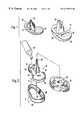
- FIG. 1is a perspective view showing a pair of tibial baseplates of alternative design for use in accordance with the present invention
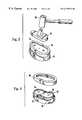
- FIG. 2is an exploded, partial perspective view showing the manner in which a tibial component is received by a tibia in accordance with the present invention
- FIG. 3is a partial perspective view showing a tibial component being secured to a tibia in accordance with the present invention.
- FIG. 4is a partial perspective view showing a cement compression ring after removal from a secured tibial component in accordance with the present invention.
- FIG. 1a pair of tibial baseplates are shown, including a stemmed porous tibial baseplate 10 and a stemmed non-porous tibial baseplate 14 .
- a central cruciate stem 18projects from a first tibial tray 22 of the porous tibial baseplate 10 .
- a continuous porous coating 24is formed on the inferior surface of the first tibial tray 22 .
- Baseplates having a porous coatingare not used in the practice of the present invention.
- the non-porous tibial baseplate 14utilizes a second tibial tray 26 having a smooth inferior surface 28 .
- a square stem 32projects from the second tibial tray 26 , and a polyethylene insert 34 is attached to the opposite, superior side of the second tibial tray 26 .
- the polyethylene insert 34replaces the diseased or damaged cartilage in the replacement joint.
- FIG. 2An asymmetric tibial baseplate 42 is shown in FIG. 2, with the asymmetry provided to optimize tibial plateau coverage.
- a central cruciate stem 46projects from the smooth inferior surface 28 in a manner similar to that shown by the porous tibial baseplate 10 of FIG. 1 .
- Tibial stemsprovide additional stability to the baseplate mounting. Where required, utilizing even longer stems can provide enhanced stability.
- a peripheral rim 48is formed about an asymmetric, smooth inferior surface 52 of the asymmetric tibial baseplate 42 .
- a pair of cancellous bone screw holes 54are formed in the asymmetric, smooth inferior surface 52 at locations intended to provide fixation in the area of greatest cancellous bone density when the asymmetric tibial baseplate 42 is attached to its appropriate location on a tibia.
- the asymmetric smooth inferior surface 52provides a receiving surface for a layer of bone cement 58 shown being applied from a bone cement applicator 62 .
- methylmethacrylateused as the bone cement
- its “set time”is generally 12-15 minutes.
- the tibial baseplate 42is ordinarily installed within bone tissue within a 3-4 minute time frame (depending upon room temperature, adhesive viscosity, and other operating room parameters) after the bone cement 58 has been applied to the receiving surface.
- a cement compression ring 66provides a circumferentially-extended peripheral wall 68 , with an attached seating ring 72 .
- the cement compression ring 66generally conforms to the outer periphery of the tibial baseplate.
- the peripheral wall 68extends beyond the inferior surface 52 of the tibial baseplate 42 , thereby enhancing the retention of bone cement within the prosthesis-bone tissue interface during securement of the prosthesis.
- This multi-piece apparatusis now ready for installation into bone tissue, which is depicted in FIG. 2 as a prepared tibial surface 76 having a central intermedullary canal 78 .
- the tibial baseplate 42 and the cement compression ring 66have been placed upon a prepared end of a tibia 82 .
- the tibial baseplate 42is preferably pressed onto the tibia 82 using a mallet 86 and a tibial baseplate impactor 88 .
- the extended peripheral wall 68contacts the prepared tibial surface first, then the tibial baseplate 42 is advanced, sliding within the cement compression ring 66 .
- the peripheral wall 68limits leakage about the periphery of the tibial baseplate interface, thereby increasing pressure within the cement column and improving penetration of cement into the cancellous bone surface.
- FIG. 4the impacting procedure has been completed, and the outer cement compression ring 66 is shown as having been removed from the tibial baseplate 42 .
- a pair of titanium cancellous bone screwsmay be received within the pair of cancellous bone screw holes 54 formed in the tibial baseplate 42 .
- the tibial baseplateis fabricated out of titanium.
- tibial baseplatesthat are appropriate for use with the present invention. Such manufacturers include the following: Sulzer Orthopedics, Johnson & Johnson, Biomet, and Zimmer.
- the cement compression ring 66must be shaped appropriately to receive the tibial baseplate.
- the extended peripheral wall 68is spaced no further than one (1) mm from the adjacent peripheral rim 48 of the tibial baseplate 42 . A greater separation increases the likelihood of lateral bone cement leakage, as well as a reduction in the bone cement pressurization and penetration adjacent any such leakage.
- the inwardly-extending seating ringis provided primarily for the convenience of the surgeon and operating room staff, and is not considered to be essential to the successful functioning of the present invention. Of greater importance is the height of the peripheral wall of the cement compression ring which should exceed the thickness of the tibial baseplate by 2-5 mm. With reference to FIG. 2, the dimension C preferably exceeds the dimension D by an amount of 2-5 mm.
- the cement compression ringis preferably fabricated out of stainless steel of thickness on the order of 1 mm. Other materials, such as aluminum and hard plastic are also appropriate, with the desired thickness varying in accordance with the strength of the fabrication material used.
- Our inventionhas been found to produce increased interdigitation of cement within the proximal tibia as compared to standard implantation techniques. It is believed that this is a result of increased cement pressure during implantation.
- each tibiawas prepared for implantation of the Natural Knee II (Trademark of Sulzer Orthopedics Inc.) tibial baseplate by resecting a planar surface on the proximal end of the tibia.
- the right tibia of each pairwas cemented using conventional cementing techniques.
- the backside of the tibial baseplatewas completely covered with cement.
- the baseplatewas then driven into the tibia and the excess cement was removed.
- each baseplatewas implanted using a cement compression ring that fit around the circumference of the tibial component.
- the ringprotruded several millimeters distally from the edge of the tibial tray. Cement was then placed in the recess formed between the ring and the backside of the tibial baseplate. The assembly of baseplate, ring and cement was placed on the tibia and the baseplate was driven into the tibia. Before the baseplate reached its seated position, the compression ring came in contact with the resected surface of the tibia thereby limiting cement extrusion during the seating process.
- Cement pressures at the baseplate-cement interfacewere measured with two electronic transducers located within the medial and lateral plateaus of the baseplate. These devices were attached to the tibial tray and were exposed to the cement mantle via medial and lateral screw holes. The pressure measurements were sampled at 100 Hz. Data collection began before the cement was placed on the distal surface of the tibial tray and continued until the cement began to set.
- the pressure history of the interface during active pressurization(i.e. the time during which the component was being seated) was summarized by the following parameters: I) the duration of the pressurization, that is, seating time, II) the maximum, minimum and mean pressure recorded within the medial and lateral compartments, III) the cumulative pressure, defined by the pressure integrated with respect to time over the period of pressurization, IV) the mean positive and mean negative pressures, and V) the cumulative positive and negative pressures.
- the tibial componentswere extracted from the cement mantle.
- One tibiawas damaged beyond repair, leaving seven pairs of tibiae available for analysis.
- the depth of cement penetrationwas measured in eight zones within the proximal tibia: Medial, Anterior-Medial, Anterior, Anterior-Lateral, Lateral, Posterior-Lateral, Posterior, and Posterior-Medial.
- Each Tibiawas cut into eight pie-like pieces with cutting planes passing through each of the measurement zones. Approximately 100 points were measured on each of the sections to accurately approximate the bony and cement surfaces.
- the measured points describing the surfaces of the distal cement boundary and the proximal bony trabeculae boundarywere used to calculate the distance between the most distal cement and most proximal bone surface at 1 mm increments on each of the sections. Using these measurements, the mean depth of cement penetration as well as the total area of penetration within each zone were calculated.
- Table 1records the average pressures recorded during implantation at medial and lateral locations. The average seating time, maximum, mean and cumulative pressures are given.
- Table 2records the depth of penetration determined after sectioning the tibiae.
- the increased maximum pressures and cumulative pressures associated with the pressurization devicehad a direct impact on the cement penetration depth as well as the penetration area.
- the average depth of cement penetrationwas 270% higher in the tibiae which were implanted using the pressurization device compared to the contralateral controls.
- the total amount of cement that penetrated the trabecular structure of the tibiacan be estimated from the aggregate area of cement-bone composite present on the 8 slices examined from each tibia. On average, the total area of penetration was 299% greater in the tibiae implanted with the compression ring (30.1 vs 75.0 mm 2 ). In both the control and device tibiae the greatest penetration area was observed in the Medial and Lateral zones, while the greatest difference in area was observed in the Posterior zone.
- the cement compression ring used with a tibiae baseplateincreased interdigitation of cement within the proximal tibia as compared to a standard procedure. It is expected that improved cement penetration will improve the long-term stability of an implanted prosthesis.
Landscapes
- Health & Medical Sciences (AREA)
- Orthopedic Medicine & Surgery (AREA)
- Life Sciences & Earth Sciences (AREA)
- Transplantation (AREA)
- General Health & Medical Sciences (AREA)
- Veterinary Medicine (AREA)
- Engineering & Computer Science (AREA)
- Biomedical Technology (AREA)
- Heart & Thoracic Surgery (AREA)
- Public Health (AREA)
- Animal Behavior & Ethology (AREA)
- Physical Education & Sports Medicine (AREA)
- Oral & Maxillofacial Surgery (AREA)
- Vascular Medicine (AREA)
- Cardiology (AREA)
- Surgery (AREA)
- Nuclear Medicine, Radiotherapy & Molecular Imaging (AREA)
- Medical Informatics (AREA)
- Molecular Biology (AREA)
- Prostheses (AREA)
Abstract
Description
| TABLE 1 |
| Pressurization Data |
| Pressure [psi] | Cummulative |
| Seating | Max | Max | Mean | Mean | Pressure [s-psi] |
| Specimen | Time | Lateral | Medial | Medial | Lateral | Medial | Lateral |
| Control | 14.72 | 34.65 | 9.23 | 1.63 | 0.85 | 19.14 | 9.92 |
| Ring | 23.78 | 42.12 | 5.51 | 2.18 | 1.91 | 48.43 | 43.07 |
| StdErr | 1.13 | 72.37 | 7.32 | 0.46 | 0.10 | 8.97 | 1.28 |
| StdErr | 2.37 | 59.08 | 3.91 | 0.18 | 0.14 | 9.68 | 4.92 |
| Change | 162% | 209% | 140% | 134% | 223% | 253% | 434% |
| P | 0.001 | 0.037 | 0.011 | 0.362 | 0.001 | 0.114 | 0.000 |
| TABLE 2 |
| Penetration Data |
| Mean Penetration [mm] | Mean Penetration Area [mm{circumflex over ( )}2] |
| Measurement | Control | Ring | Control | Ring |
| Location | Mean | Se | Mean | se | Change | Mean | Se | Mean | se | Change |
| Med | 1.69 | 0.30 | 4.79 | 0.95 | 284% | 47.77 | 10.12 | 140.37 | 25.13 | 294% |
| Ant Med | 1.38 | 0.25 | 3.17 | 0.25 | 229% | 31.22 | 5.10 | 62.23 | 4.13 | 199% |
| Ant | 1.30 | 0.24 | 3.81 | 0.59 | 292% | 23.45 | 5.58 | 72.09 | 13.14 | 307% |
| Ant Lat | 1.27 | 0.33 | 3.36 | 0.61 | 265% | 24.06 | 6.34 | 57.09 | 12.32 | 237% |
| Lat | 1.88 | 0.37 | 3.75 | 0.63 | 199% | 49.38 | 12.34 | 99.58 | 18.29 | 202% |
| Pos Lat | 1.59 | 0.30 | 2.42 | 0.40 | 153% | 36.83 | 7.71 | 42.95 | 7.23 | 117% |
| Pos | 0.83 | 0.10 | 3.60 | 0.40 | 437% | 8.60 | 1.36 | 59.49 | 8.31 | 692% |
| Pos Med | 1.07 | 0.19 | 3.24 | 0.55 | 302% | 19.11 | 4.44 | 66.55 | 11.71 | 348% |
Claims (30)
Priority Applications (6)
| Application Number | Priority Date | Filing Date | Title |
|---|---|---|---|
| US09/432,901US6179876B1 (en) | 1998-11-04 | 1999-11-02 | Orthopedic prosthesis with cement compression ring and method |
| JP2000579147AJP2003521957A (en) | 1998-11-04 | 1999-11-04 | Orthopedic prosthesis with cement compression ring |
| CA002358696ACA2358696C (en) | 1998-11-04 | 1999-11-04 | Orthopedic prosthesis with cement compression ring |
| DE69924297TDE69924297T2 (en) | 1998-11-04 | 1999-11-04 | ORTHOPEDIC PROSTHESIS WITH CEMENT COMPRESSION RING |
| EP99960201AEP1154741B1 (en) | 1998-11-04 | 1999-11-04 | Orthopedic prosthesis with cement compression ring |
| PCT/US1999/025966WO2000025700A2 (en) | 1998-11-04 | 1999-11-04 | Orthopedic prosthesis with cement compression ring |
Applications Claiming Priority (2)
| Application Number | Priority Date | Filing Date | Title |
|---|---|---|---|
| US10704098P | 1998-11-04 | 1998-11-04 | |
| US09/432,901US6179876B1 (en) | 1998-11-04 | 1999-11-02 | Orthopedic prosthesis with cement compression ring and method |
Publications (1)
| Publication Number | Publication Date |
|---|---|
| US6179876B1true US6179876B1 (en) | 2001-01-30 |
Family
ID=26804322
Family Applications (1)
| Application Number | Title | Priority Date | Filing Date |
|---|---|---|---|
| US09/432,901Expired - Fee RelatedUS6179876B1 (en) | 1998-11-04 | 1999-11-02 | Orthopedic prosthesis with cement compression ring and method |
Country Status (6)
| Country | Link |
|---|---|
| US (1) | US6179876B1 (en) |
| EP (1) | EP1154741B1 (en) |
| JP (1) | JP2003521957A (en) |
| CA (1) | CA2358696C (en) |
| DE (1) | DE69924297T2 (en) |
| WO (1) | WO2000025700A2 (en) |
Cited By (28)
| Publication number | Priority date | Publication date | Assignee | Title |
|---|---|---|---|---|
| US20060155292A1 (en)* | 2002-09-19 | 2006-07-13 | Jeganath Krishnan | Implant clamp and method |
| US20060155380A1 (en)* | 2002-10-23 | 2006-07-13 | Mako Surgical Corporation | Modular femoral component for a total knee joint replacement for minimally invasive implantation |
| US20060259149A1 (en)* | 2005-03-07 | 2006-11-16 | David Barrett | Surgical assembly |
| US20080119941A1 (en)* | 2006-11-22 | 2008-05-22 | Jai-Gon Seo | Tibia impacter |
| US20080167722A1 (en)* | 2007-01-10 | 2008-07-10 | Biomet Manufacturing Corp. | Knee Joint Prosthesis System and Method for Implantation |
| US7445639B2 (en) | 2001-02-23 | 2008-11-04 | Biomet Manufacturing Corp. | Knee joint prosthesis |
| US20080306602A1 (en)* | 2007-06-07 | 2008-12-11 | Worland Richard L | Tibia Cement Impaction System |
| US7497874B1 (en) | 2001-02-23 | 2009-03-03 | Biomet Manufacturing Corp. | Knee joint prosthesis |
| US20090149964A1 (en)* | 2007-10-10 | 2009-06-11 | Biomet Manufacturing Corp. | Knee joint prosthesis system and method for implantation |
| US20090299482A1 (en)* | 2007-01-10 | 2009-12-03 | Biomet Manufacturing Corp. | Knee Joint Prosthesis System and Method for Implantation |
| US20100100190A1 (en)* | 2008-10-17 | 2010-04-22 | Biomet Manufacturing Corp. | Tibial tray having a reinforcing member |
| US20110029090A1 (en)* | 2007-09-25 | 2011-02-03 | Depuy Products, Inc. | Prosthesis with modular extensions |
| US20110167601A1 (en)* | 2008-10-22 | 2011-07-14 | Innovative Supply, Inc. | Restoration/embalming kit |
| US20110178605A1 (en)* | 2010-01-21 | 2011-07-21 | Depuy Products, Inc. | Knee prosthesis system |
| USD649246S1 (en)* | 2011-04-18 | 2011-11-22 | E.F. Precision Group, Inc. | Orthopedic mallet |
| US8128703B2 (en) | 2007-09-28 | 2012-03-06 | Depuy Products, Inc. | Fixed-bearing knee prosthesis having interchangeable components |
| US8187280B2 (en) | 2007-10-10 | 2012-05-29 | Biomet Manufacturing Corp. | Knee joint prosthesis system and method for implantation |
| US8287601B2 (en) | 2010-09-30 | 2012-10-16 | Depuy Products, Inc. | Femoral component of a knee prosthesis having an angled cement pocket |
| US8317870B2 (en) | 2010-09-30 | 2012-11-27 | Depuy Products, Inc. | Tibial component of a knee prosthesis having an angled cement pocket |
| US8328873B2 (en) | 2007-01-10 | 2012-12-11 | Biomet Manufacturing Corp. | Knee joint prosthesis system and method for implantation |
| US8734523B2 (en) | 2012-05-31 | 2014-05-27 | Howmedica Osteonics Corp. | Limited motion tibial bearing |
| US20140277548A1 (en)* | 2013-03-15 | 2014-09-18 | Mako Surgical Corp. | Unicondylar tibial knee implant |
| US9204967B2 (en) | 2007-09-28 | 2015-12-08 | Depuy (Ireland) | Fixed-bearing knee prosthesis having interchangeable components |
| US9278003B2 (en) | 2007-09-25 | 2016-03-08 | Depuy (Ireland) | Prosthesis for cementless fixation |
| US20170071745A1 (en)* | 2015-02-16 | 2017-03-16 | Augusto Magagnoli | Method of making a spacer device having a containment body |
| US9949837B2 (en) | 2013-03-07 | 2018-04-24 | Howmedica Osteonics Corp. | Partially porous bone implant keel |
| US20190029843A1 (en)* | 2010-04-09 | 2019-01-31 | Centinel Spine, Llc | Intervertebral implant |
| US12329629B2 (en) | 2021-06-08 | 2025-06-17 | Howmedica Osteonics Corp. | Additive manufacturing of porous coatings separate from substrate |
Families Citing this family (3)
| Publication number | Priority date | Publication date | Assignee | Title |
|---|---|---|---|---|
| US20100100191A1 (en)* | 2008-10-17 | 2010-04-22 | Biomet Manufacturing Corp. | Tibial Tray Having a Reinforcing Member |
| DE102011050361B4 (en)* | 2011-05-13 | 2017-11-16 | Philip Kasten | Instrument attachment on a cementing instrument and method for introducing bone cement by pressure cementing |
| EP4473945A1 (en)* | 2023-06-09 | 2024-12-11 | CeramTec GmbH | Tibial tray with a tibial tray shaft structure and an artificial knee joint |
Citations (8)
| Publication number | Priority date | Publication date | Assignee | Title |
|---|---|---|---|---|
| US4285071A (en) | 1979-07-02 | 1981-08-25 | Nelson Carl L | Method of securing a prosthesis using cement spacers |
| US4593685A (en) | 1983-10-17 | 1986-06-10 | Pfizer Hospital Products Group Inc. | Bone cement applicator |
| US5171276A (en) | 1990-01-08 | 1992-12-15 | Caspari Richard B | Knee joint prosthesis |
| US5201768A (en) | 1990-01-08 | 1993-04-13 | Caspari Richard B | Prosthesis for implant on the tibial plateau of the knee |
| US5326363A (en)* | 1992-09-14 | 1994-07-05 | Zimmer, Inc. | Provisional implant |
| EP0650707A1 (en) | 1993-10-29 | 1995-05-03 | Howmedica International Inc. | Apparatus for implanting an acetabular cup |
| US5876460A (en) | 1996-09-06 | 1999-03-02 | Bloebaum; Roy D. | Cemented prosthetic component and placement method |
| US6045581A (en)* | 1997-12-12 | 2000-04-04 | Sulzer Orthopedics Inc. | Implantable prosthesis having textured bearing surfaces |
- 1999
- 1999-11-02USUS09/432,901patent/US6179876B1/ennot_activeExpired - Fee Related
- 1999-11-04EPEP99960201Apatent/EP1154741B1/ennot_activeExpired - Lifetime
- 1999-11-04JPJP2000579147Apatent/JP2003521957A/enactivePending
- 1999-11-04DEDE69924297Tpatent/DE69924297T2/ennot_activeExpired - Lifetime
- 1999-11-04WOPCT/US1999/025966patent/WO2000025700A2/enactiveIP Right Grant
- 1999-11-04CACA002358696Apatent/CA2358696C/ennot_activeExpired - Fee Related
Patent Citations (8)
| Publication number | Priority date | Publication date | Assignee | Title |
|---|---|---|---|---|
| US4285071A (en) | 1979-07-02 | 1981-08-25 | Nelson Carl L | Method of securing a prosthesis using cement spacers |
| US4593685A (en) | 1983-10-17 | 1986-06-10 | Pfizer Hospital Products Group Inc. | Bone cement applicator |
| US5171276A (en) | 1990-01-08 | 1992-12-15 | Caspari Richard B | Knee joint prosthesis |
| US5201768A (en) | 1990-01-08 | 1993-04-13 | Caspari Richard B | Prosthesis for implant on the tibial plateau of the knee |
| US5326363A (en)* | 1992-09-14 | 1994-07-05 | Zimmer, Inc. | Provisional implant |
| EP0650707A1 (en) | 1993-10-29 | 1995-05-03 | Howmedica International Inc. | Apparatus for implanting an acetabular cup |
| US5876460A (en) | 1996-09-06 | 1999-03-02 | Bloebaum; Roy D. | Cemented prosthetic component and placement method |
| US6045581A (en)* | 1997-12-12 | 2000-04-04 | Sulzer Orthopedics Inc. | Implantable prosthesis having textured bearing surfaces |
Cited By (55)
| Publication number | Priority date | Publication date | Assignee | Title |
|---|---|---|---|---|
| US7445639B2 (en) | 2001-02-23 | 2008-11-04 | Biomet Manufacturing Corp. | Knee joint prosthesis |
| US7497874B1 (en) | 2001-02-23 | 2009-03-03 | Biomet Manufacturing Corp. | Knee joint prosthesis |
| US20060155292A1 (en)* | 2002-09-19 | 2006-07-13 | Jeganath Krishnan | Implant clamp and method |
| US7799084B2 (en) | 2002-10-23 | 2010-09-21 | Mako Surgical Corp. | Modular femoral component for a total knee joint replacement for minimally invasive implantation |
| US20060155380A1 (en)* | 2002-10-23 | 2006-07-13 | Mako Surgical Corporation | Modular femoral component for a total knee joint replacement for minimally invasive implantation |
| US20060259149A1 (en)* | 2005-03-07 | 2006-11-16 | David Barrett | Surgical assembly |
| US8034058B2 (en) | 2005-03-17 | 2011-10-11 | Depuy International Limited | Tibial cement skirt assembly |
| US20080119941A1 (en)* | 2006-11-22 | 2008-05-22 | Jai-Gon Seo | Tibia impacter |
| US8480751B2 (en) | 2007-01-10 | 2013-07-09 | Biomet Manufacturing, Llc | Knee joint prosthesis system and method for implantation |
| US20090299482A1 (en)* | 2007-01-10 | 2009-12-03 | Biomet Manufacturing Corp. | Knee Joint Prosthesis System and Method for Implantation |
| US8328873B2 (en) | 2007-01-10 | 2012-12-11 | Biomet Manufacturing Corp. | Knee joint prosthesis system and method for implantation |
| US8157869B2 (en) | 2007-01-10 | 2012-04-17 | Biomet Manufacturing Corp. | Knee joint prosthesis system and method for implantation |
| US8936648B2 (en) | 2007-01-10 | 2015-01-20 | Biomet Manufacturing, Llc | Knee joint prosthesis system and method for implantation |
| US8163028B2 (en) | 2007-01-10 | 2012-04-24 | Biomet Manufacturing Corp. | Knee joint prosthesis system and method for implantation |
| US20080167722A1 (en)* | 2007-01-10 | 2008-07-10 | Biomet Manufacturing Corp. | Knee Joint Prosthesis System and Method for Implantation |
| US20080306602A1 (en)* | 2007-06-07 | 2008-12-11 | Worland Richard L | Tibia Cement Impaction System |
| US9398956B2 (en) | 2007-09-25 | 2016-07-26 | Depuy (Ireland) | Fixed-bearing knee prosthesis having interchangeable components |
| US20110029090A1 (en)* | 2007-09-25 | 2011-02-03 | Depuy Products, Inc. | Prosthesis with modular extensions |
| US9278003B2 (en) | 2007-09-25 | 2016-03-08 | Depuy (Ireland) | Prosthesis for cementless fixation |
| US8632600B2 (en)* | 2007-09-25 | 2014-01-21 | Depuy (Ireland) | Prosthesis with modular extensions |
| US8128703B2 (en) | 2007-09-28 | 2012-03-06 | Depuy Products, Inc. | Fixed-bearing knee prosthesis having interchangeable components |
| US9204967B2 (en) | 2007-09-28 | 2015-12-08 | Depuy (Ireland) | Fixed-bearing knee prosthesis having interchangeable components |
| US9763793B2 (en) | 2007-10-10 | 2017-09-19 | Biomet Manufacturing, Llc | Knee joint prosthesis system and method for implantation |
| US10736747B2 (en) | 2007-10-10 | 2020-08-11 | Biomet Manufacturing, Llc | Knee joint prosthesis system and method for implantation |
| US8187280B2 (en) | 2007-10-10 | 2012-05-29 | Biomet Manufacturing Corp. | Knee joint prosthesis system and method for implantation |
| US20090149964A1 (en)* | 2007-10-10 | 2009-06-11 | Biomet Manufacturing Corp. | Knee joint prosthesis system and method for implantation |
| US8562616B2 (en) | 2007-10-10 | 2013-10-22 | Biomet Manufacturing, Llc | Knee joint prosthesis system and method for implantation |
| US20100100190A1 (en)* | 2008-10-17 | 2010-04-22 | Biomet Manufacturing Corp. | Tibial tray having a reinforcing member |
| US8771364B2 (en) | 2008-10-17 | 2014-07-08 | Biomet Manufacturing, Llc | Tibial tray having a reinforcing member |
| US20110167601A1 (en)* | 2008-10-22 | 2011-07-14 | Innovative Supply, Inc. | Restoration/embalming kit |
| US9011547B2 (en) | 2010-01-21 | 2015-04-21 | Depuy (Ireland) | Knee prosthesis system |
| US20110178605A1 (en)* | 2010-01-21 | 2011-07-21 | Depuy Products, Inc. | Knee prosthesis system |
| US12102543B2 (en) | 2010-04-09 | 2024-10-01 | Centinel Spine, Llc | Inter vertebral implant |
| US11419734B2 (en)* | 2010-04-09 | 2022-08-23 | Centinelspine, Llc | Intervertebral implant |
| US20190029843A1 (en)* | 2010-04-09 | 2019-01-31 | Centinel Spine, Llc | Intervertebral implant |
| US8845746B2 (en) | 2010-09-30 | 2014-09-30 | Depuy (Ireland) | Femoral component of a knee prosthesis having an angled posterior cement pocket |
| US8317870B2 (en) | 2010-09-30 | 2012-11-27 | Depuy Products, Inc. | Tibial component of a knee prosthesis having an angled cement pocket |
| US8287601B2 (en) | 2010-09-30 | 2012-10-16 | Depuy Products, Inc. | Femoral component of a knee prosthesis having an angled cement pocket |
| US9724202B2 (en) | 2010-09-30 | 2017-08-08 | Depuy Ireland Unlimited Company | Femoral component of a knee prosthesis having an angled cement pocket |
| USD649246S1 (en)* | 2011-04-18 | 2011-11-22 | E.F. Precision Group, Inc. | Orthopedic mallet |
| US8734523B2 (en) | 2012-05-31 | 2014-05-27 | Howmedica Osteonics Corp. | Limited motion tibial bearing |
| USD967960S1 (en) | 2013-03-07 | 2022-10-25 | Howmedica Osteonics Corp. | Porous tibial implant |
| US11564801B2 (en) | 2013-03-07 | 2023-01-31 | Howmedica Osteonics Corp. | Partially porous tibial component |
| US9949837B2 (en) | 2013-03-07 | 2018-04-24 | Howmedica Osteonics Corp. | Partially porous bone implant keel |
| US12343261B2 (en) | 2013-03-07 | 2025-07-01 | Howmedica Osteonics Corp. | Partially porous tibial component |
| US12279961B2 (en) | 2013-03-07 | 2025-04-22 | Howmedica Osteonics Corp. | Method of manufacturing a tibial implant |
| US12268609B2 (en) | 2013-03-07 | 2025-04-08 | Howmedica Osteonics Corp. | Method of manufacturing a tibial implant |
| US20140277548A1 (en)* | 2013-03-15 | 2014-09-18 | Mako Surgical Corp. | Unicondylar tibial knee implant |
| US9907658B2 (en) | 2013-03-15 | 2018-03-06 | Mako Surgical Corp. | Unicondylar tibial knee implant |
| US9445909B2 (en)* | 2013-03-15 | 2016-09-20 | Mako Surgical Corp. | Unicondylar tibial knee implant |
| US20140343681A1 (en)* | 2013-03-15 | 2014-11-20 | Mako Surgical Corp. | Unicondylar tibial knee implant |
| US9744044B2 (en)* | 2013-03-15 | 2017-08-29 | Mako Surgical Corp. | Unicondylar tibial knee implant |
| US20170071745A1 (en)* | 2015-02-16 | 2017-03-16 | Augusto Magagnoli | Method of making a spacer device having a containment body |
| US10492914B2 (en)* | 2015-02-16 | 2019-12-03 | Cossington Limited | Method of making a spacer device having a containment body |
| US12329629B2 (en) | 2021-06-08 | 2025-06-17 | Howmedica Osteonics Corp. | Additive manufacturing of porous coatings separate from substrate |
Also Published As
| Publication number | Publication date |
|---|---|
| EP1154741B1 (en) | 2005-03-16 |
| CA2358696A1 (en) | 2000-05-11 |
| JP2003521957A (en) | 2003-07-22 |
| CA2358696C (en) | 2005-03-01 |
| DE69924297T2 (en) | 2006-04-13 |
| WO2000025700A3 (en) | 2000-09-08 |
| DE69924297D1 (en) | 2005-04-21 |
| EP1154741A2 (en) | 2001-11-21 |
| WO2000025700A2 (en) | 2000-05-11 |
| WO2000025700A9 (en) | 2000-11-02 |
Similar Documents
| Publication | Publication Date | Title |
|---|---|---|
| US6179876B1 (en) | Orthopedic prosthesis with cement compression ring and method | |
| EP0183669B1 (en) | Joint prosthesis | |
| US3987500A (en) | Surgically implantable total ankle prosthesis | |
| AU651085B2 (en) | Knee joint prosthesis | |
| US5207711A (en) | Knee joint prosthesis | |
| US4514865A (en) | Stemmed femoral component for the human hip | |
| US4808185A (en) | Tibial prosthesis, template and reamer | |
| US4406023A (en) | Stemmed femoral component for the human hip | |
| US5201768A (en) | Prosthesis for implant on the tibial plateau of the knee | |
| JP4283075B2 (en) | Providing method and kit for joint part, cue stick, shoulder arthroplasty | |
| CA2628841C (en) | Mounting system and method for enhancing implant fixation to bone | |
| US20120215311A1 (en) | Arthroplasty shim | |
| US5876460A (en) | Cemented prosthetic component and placement method | |
| WO1991015168A1 (en) | Recessed patellar prosthesis | |
| WO1995033423A1 (en) | Hybrid tibial tray knee prosthesis | |
| US8690955B2 (en) | Device for unicompartmental knee arthroplasty | |
| US20210338448A1 (en) | Talar Ankle Implant | |
| WO2010042941A2 (en) | Implants for the treatment of osteoarthritis (oa) of the knee | |
| Jacob | Biomechanical principles and design details of the thrust plate prosthesis | |
| Lee et al. | Effects of screw types in cementless fixation of tibial tray implants: stability and strength assessment | |
| CA2304677C (en) | Cemented prosthetic component and placement method | |
| Cetin et al. | Arthroplasty as a Choice of Treatment in Hip Surgery | |
| Park | Hard tissue replacement implants | |
| Citarella | A review of acetabular prostheses for total hip arthroplasty |
Legal Events
| Date | Code | Title | Description |
|---|---|---|---|
| AS | Assignment | Owner name:UBS AG, STAMFORD BRANCH AS SECURITY AGENT FOR THE Free format text:SECURITY INTEREST;ASSIGNORS:CENTERPULSE ORTHOPEDICS INC.;CENTERPULSE USA HOLDING CO., CORPORATION, DELAWARE;CENTERPULSE USA INC., CORPORATION, DELAWARE;AND OTHERS;REEL/FRAME:013467/0328 Effective date:20021029 | |
| AS | Assignment | Owner name:CENTERPULSE ORTHOPEDICS INC., TEXAS Free format text:CHANGE OF NAME;ASSIGNOR:SULZER ORTHOPEDICS INC.;REEL/FRAME:013516/0549 Effective date:20020930 | |
| AS | Assignment | Owner name:CENTERPULSE USA INC., TEXAS Free format text:PATENT RELEASE AGREEMENT;ASSIGNOR:UBS AG, STAMFORD BRANCH;REEL/FRAME:014699/0404 Effective date:20031002 | |
| FEPP | Fee payment procedure | Free format text:PAYOR NUMBER ASSIGNED (ORIGINAL EVENT CODE: ASPN); ENTITY STATUS OF PATENT OWNER: LARGE ENTITY | |
| FPAY | Fee payment | Year of fee payment:4 | |
| AS | Assignment | Owner name:ZIMMER AUSTIN, INC., TEXAS Free format text:CHANGE OF NAME;ASSIGNOR:CENTERPULSE ORTHOPEDICS INC.;REEL/FRAME:016263/0264 Effective date:20040602 | |
| AS | Assignment | Owner name:CENTERPULSE ORTHOPEDICS INC., TEXAS Free format text:CHANGE OF NAME;ASSIGNOR:SULZER ORTHOPEDICS INC.;REEL/FRAME:016761/0136 Effective date:20020930 | |
| AS | Assignment | Owner name:ZIMMER, INC., INDIANA Free format text:CHANGE OF NAME;ASSIGNOR:ZIMMER AUSTIN, INC.;REEL/FRAME:017435/0714 Effective date:20060208 | |
| FPAY | Fee payment | Year of fee payment:8 | |
| REMI | Maintenance fee reminder mailed | ||
| LAPS | Lapse for failure to pay maintenance fees | ||
| STCH | Information on status: patent discontinuation | Free format text:PATENT EXPIRED DUE TO NONPAYMENT OF MAINTENANCE FEES UNDER 37 CFR 1.362 | |
| FP | Lapsed due to failure to pay maintenance fee | Effective date:20130130 |