US6179839B1 - Bone fusion apparatus and method - Google Patents
Bone fusion apparatus and methodDownload PDFInfo
- Publication number
- US6179839B1 US6179839B1US09/399,021US39902199AUS6179839B1US 6179839 B1US6179839 B1US 6179839B1US 39902199 AUS39902199 AUS 39902199AUS 6179839 B1US6179839 B1US 6179839B1
- Authority
- US
- United States
- Prior art keywords
- bone
- plate
- burr
- bones
- away
- Prior art date
- Legal status (The legal status is an assumption and is not a legal conclusion. Google has not performed a legal analysis and makes no representation as to the accuracy of the status listed.)
- Expired - Lifetime
Links
- 210000000988bone and boneAnatomy0.000titleclaimsabstractdescription330
- 230000004927fusionEffects0.000titleclaimsabstractdescription156
- 238000000034methodMethods0.000titleclaimsabstractdescription34
- 210000000707wristAnatomy0.000claimsabstractdescription70
- 230000006835compressionEffects0.000claimsabstractdescription9
- 238000007906compressionMethods0.000claimsabstractdescription9
- 230000008878couplingEffects0.000claimsdescription8
- 238000010168coupling processMethods0.000claimsdescription8
- 238000005859coupling reactionMethods0.000claimsdescription8
- 210000002753capitate boneAnatomy0.000claimsdescription7
- 210000000693hamate boneAnatomy0.000claimsdescription7
- 239000000463materialSubstances0.000claimsdescription6
- 229910001220stainless steelInorganic materials0.000claimsdescription4
- 239000010935stainless steelSubstances0.000claimsdescription4
- 210000003991lunate boneAnatomy0.000claims6
- 210000000236metacarpal boneAnatomy0.000abstractdescription8
- 240000004282Grewia occidentalisSpecies0.000description6
- 208000037873arthrodesisDiseases0.000description6
- 210000000610foot boneAnatomy0.000description4
- 201000008482osteoarthritisDiseases0.000description3
- 241000283984RodentiaSpecies0.000description2
- 206010003246arthritisDiseases0.000description2
- 239000002775capsuleSubstances0.000description2
- 238000010276constructionMethods0.000description2
- 238000002224dissectionMethods0.000description2
- 210000003041ligamentAnatomy0.000description2
- 206010039073rheumatoid arthritisDiseases0.000description2
- 239000000126substanceSubstances0.000description2
- 210000002435tendonAnatomy0.000description2
- 206010015719ExsanguinationDiseases0.000description1
- 230000003444anaesthetic effectEffects0.000description1
- 210000003010carpal boneAnatomy0.000description1
- 210000000845cartilageAnatomy0.000description1
- 238000001804debridementMethods0.000description1
- 230000003247decreasing effectEffects0.000description1
- 230000007547defectEffects0.000description1
- 230000007812deficiencyEffects0.000description1
- 201000010099diseaseDiseases0.000description1
- 208000037265diseases, disorders, signs and symptomsDiseases0.000description1
- 230000000694effectsEffects0.000description1
- 239000000835fiberSubstances0.000description1
- 230000002262irrigationEffects0.000description1
- 238000003973irrigationMethods0.000description1
- QSHDDOUJBYECFT-UHFFFAOYSA-NmercuryChemical compound[Hg]QSHDDOUJBYECFT-UHFFFAOYSA-N0.000description1
- 229910052753mercuryInorganic materials0.000description1
- 238000007500overflow downdraw methodMethods0.000description1
- 238000012856packingMethods0.000description1
- 206010033675panniculitisDiseases0.000description1
- 210000002979radial nerveAnatomy0.000description1
- 238000010079rubber tappingMethods0.000description1
- 230000001953sensory effectEffects0.000description1
- 210000004872soft tissueAnatomy0.000description1
- 230000006641stabilisationEffects0.000description1
- 238000011105stabilizationMethods0.000description1
- 210000004304subcutaneous tissueAnatomy0.000description1
- 210000000658ulnar nerveAnatomy0.000description1
- 210000001364upper extremityAnatomy0.000description1
- 210000003857wrist jointAnatomy0.000description1
Images


Classifications
- A—HUMAN NECESSITIES
- A61—MEDICAL OR VETERINARY SCIENCE; HYGIENE
- A61B—DIAGNOSIS; SURGERY; IDENTIFICATION
- A61B17/00—Surgical instruments, devices or methods
- A61B17/16—Instruments for performing osteoclasis; Drills or chisels for bones; Trepans
- A61B17/1662—Instruments for performing osteoclasis; Drills or chisels for bones; Trepans for particular parts of the body
- A61B17/1686—Instruments for performing osteoclasis; Drills or chisels for bones; Trepans for particular parts of the body for the hand or wrist
- A—HUMAN NECESSITIES
- A61—MEDICAL OR VETERINARY SCIENCE; HYGIENE
- A61B—DIAGNOSIS; SURGERY; IDENTIFICATION
- A61B17/00—Surgical instruments, devices or methods
- A61B17/16—Instruments for performing osteoclasis; Drills or chisels for bones; Trepans
- A61B17/1659—Surgical rasps, files, planes, or scrapers
- A—HUMAN NECESSITIES
- A61—MEDICAL OR VETERINARY SCIENCE; HYGIENE
- A61B—DIAGNOSIS; SURGERY; IDENTIFICATION
- A61B17/00—Surgical instruments, devices or methods
- A61B17/56—Surgical instruments or methods for treatment of bones or joints; Devices specially adapted therefor
- A61B17/58—Surgical instruments or methods for treatment of bones or joints; Devices specially adapted therefor for osteosynthesis, e.g. bone plates, screws or setting implements
- A61B17/68—Internal fixation devices, including fasteners and spinal fixators, even if a part thereof projects from the skin
- A61B17/80—Cortical plates, i.e. bone plates; Instruments for holding or positioning cortical plates, or for compressing bones attached to cortical plates
- A61B17/8061—Cortical plates, i.e. bone plates; Instruments for holding or positioning cortical plates, or for compressing bones attached to cortical plates specially adapted for particular bones
- A—HUMAN NECESSITIES
- A61—MEDICAL OR VETERINARY SCIENCE; HYGIENE
- A61B—DIAGNOSIS; SURGERY; IDENTIFICATION
- A61B17/00—Surgical instruments, devices or methods
- A61B2017/00477—Coupling
- A—HUMAN NECESSITIES
- A61—MEDICAL OR VETERINARY SCIENCE; HYGIENE
- A61B—DIAGNOSIS; SURGERY; IDENTIFICATION
- A61B17/00—Surgical instruments, devices or methods
- A61B17/16—Instruments for performing osteoclasis; Drills or chisels for bones; Trepans
- A61B2017/1602—Mills
- Y—GENERAL TAGGING OF NEW TECHNOLOGICAL DEVELOPMENTS; GENERAL TAGGING OF CROSS-SECTIONAL TECHNOLOGIES SPANNING OVER SEVERAL SECTIONS OF THE IPC; TECHNICAL SUBJECTS COVERED BY FORMER USPC CROSS-REFERENCE ART COLLECTIONS [XRACs] AND DIGESTS
- Y10—TECHNICAL SUBJECTS COVERED BY FORMER USPC
- Y10S—TECHNICAL SUBJECTS COVERED BY FORMER USPC CROSS-REFERENCE ART COLLECTIONS [XRACs] AND DIGESTS
- Y10S606/00—Surgery
- Y10S606/902—Cortical plate specifically adapted for a particular bone
- Y10S606/906—Small bone plate
Definitions
- the present inventionrelates generally to orthopaedic bone apparatuses and methods, and more particularly, to an anatomical bone fusion apparatus and method which can be utilized for bone fusion in a variety of orthopaedic settings, such as, for example, for wrist bone fusion.
- bone fusion platefor attaching to bones at a desired location to position the bones relative to one another wherein bones beneath the plate can be fused together.
- bone plateswhich have commonly been used to date are typically flat along a single plane and include holes for attachment of bone fasteners, such as bone screws, to bones below. This type of attachment of a bone plate to the bones below typically provides vertical compression only between the bones and the bone plate above and does not provide for any kind of radial or lateral compression which can urge the bones toward one another and which is highly advantageous in bone fusion.
- Bone plates suffering the above-mentioned disadvantagesexist in a variety of configurations and can be adapted for use at various anatomical locations, such as, for example, with wrist bones, foot bones, cranial-facial bones, and bones at any other location suitable for bone fusion.
- a wrist fusion apparatussuch as a wrist fusion plate to be used in arthrodesis to fuse bones of the wrist area of a patient in a desired orientation.
- a variety of configurations and designs of fusion plates specifically for use with wristsexist within the prior art for utilization in this manner.
- a dorsal wrist fusion plateis indicated in patients with osteoarthritis or post-traumatic wrist arthritis, conditions involving significant loss of bone substance, and failed partial or limited wrist arthrodesis. Wrist arthrodesis can also be successfully utilized in patients with carpal instability.
- a fusion platecan be utilized in patients with rheumatoid arthritis, although simpler stabilization techniques are currently fairly predictable. Contraindications to utilizing a wrist fusion plate adapted for fusion in a limited manner as recognized by those of skill in the art include any concomitant disease or deficiency which may compromise the function of the plate.
- Some types of wrist fusion apparatusesattach to the radius and extend from there to a metacarpal, such as the third metacarpal, of the hand for utilization in wrist fusion.
- Wrist fusion apparatuses of this varietyare typically fastened both to the radius and to the third metacarpal by bone screws, and wrist fusion apparatuses of this variety also therefore overlie the carpus area and the bones of the carpus area which are positioned between the radius and the metacarpal bones.
- bone graftscan be packed between the radius, the carpus area bones, and the metacarpals after such a wrist fusion plate is in place, and the bone grafts typically will bond with the adjacent bones in order to create a fused bone mass at the wrist joint.
- U.S. Pat. No. 5,853,413 to Carter et aldiscloses such a wrist fusion apparatus in the form of a plate configured to extend over the carpus area and to position at least one metacarpal relative to the radius.
- a saddle portionis included in the wrist fusion plate and is placed over the carpus area.
- a proximal endextends from the saddle portion and is attachable to the radius, while a distal end extends from the saddle portion and is attachable to one of the metacarpals.
- the proximal end extending from the saddle portiondefines a first longitudinal axis
- the distal end extending from the saddle portiondefines a second longitudinal axis wherein the first and second longitudinal axes are not actually aligned in a medial-lateral direction.
- Wrist fusion plate apparatuses and methods such as that disclosed in Carter et al .require attachment of a portion of the wrist fusion plate to one or more of the metacarpals of the hand as well as to the radius.
- the resulting bone fusioncan be referred to as total wrist fusion and will typically render a person with no ability to flex the subject wrist for abduction or adduction because of the total fusion of the carpal area bones with the radius and one or more metacarpals.
- the resulting fusioncan be referred to as partial or limited wrist fusion as compared to the total wrist fusion created when the radius and a metacarpal are also fused with the carpal bones.
- a bone fusion apparatus for wrist bone fusion or for fusion of other area bonesand regardless of whether a bone fusion apparatus is adapted for limited wrist fusion or for total wrist fusion, slippage or sliding of the bone fusion apparatus is a common problem which can often be encountered during the affixation or fastening of a bone fusion apparatus, especially for affixation of bone fusion apparatuses for limited, wrist bone fusion.
- the procedure of screwing in the bone screws which are typically used as fasteners for bone fusion apparatusescan be quite difficult to accomplish without some undesirable movement of the bone fusion apparatus itself. Such movement therefore can make it very difficult to precisely position and affix bone fusion apparatuses.
- the present inventionprovides a novel bone fusion apparatus and method for positioning bones in a desired area relative to one another and fusing the bones.
- the inventioncan be adapted for use with a variety of different bones in a variety of different anatomical locations for bone fusion.
- the present inventionis also particularly suitable for fusing wrist bones and can be easily utilized by attachment to a variety of wrist bones, such as, for example, the carpus area bones, the radius bone, and/or one or more metacarpal bones.
- the bone fusion apparatuscomprises a three dimensional annular plate having an outer side for at least partially contacting bone and an opposite inner side.
- the platehas a top outer edge of greatest diameter and a smaller diameter, bottom inner edge which defines an at least substantially central opening through the plate.
- the plateis substantially conical in shape such that the plate tapers outwardly from the inner edge of the plate to the outer edge of the plate.
- the platedefines a plurality of preferably countersunk holes therethrough between the inner edge and the outer edge, wherein each of the holes is adapted for receiving a bone fastener such as a bone screw for attaching the plate to a plurality of bones, such as, for example, a plurality of carpus area bones.
- the bone fusion apparatuscan particularly be positioned such that at least one hole is positioned and aligned over each of the lunate, triquetrium, hamate, and capitate bones and attached by bone screws thereto.
- the bone fusion apparatus of the present inventioncan be utilized for wrist fusion without attachment to the radius bone or to a metacarpal bone as desired.
- the bone fusion apparatuscan attach to and be used with a variety of bones of the wrist for total or limited wrist bone fusion.
- a bone burr and differing handleswhich can easily be advantageously utilized to precisely position the burr bone at a location where the bone fusion apparatus is to be placed in order for the bone fusion apparatus to precisely be positioned and affixed for bone fusion.
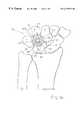
- FIG. 1A of the drawingsis a top plan view of the bone fusion apparatus according to the present invention in a preferred embodiment shown positioned over a plurality of carpus area bones;
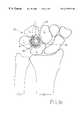
- FIG. 1B of the drawingsis identical to FIG. 1A but illustrating the bone fusion apparatus according to the present invention secured in place by a plurality of bone screws utilized as fasteners;
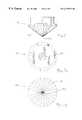
- FIG. 2 of the drawingsis an isolated top plan view of the bone fusion apparatus according to the present invention
- FIG. 3 of the drawingsis an isolated bottom plan view of the bone fusion apparatus according to the present invention.
- FIG. 4 of the drawingsis an elevated side view of the bone fusion apparatus according to the present invention.
- FIG. 5 of the drawingsis a cross-sectional view of the bone fusion apparatus according to the present invention drawn along line 5 — 5 of FIG. 2 of the drawings;
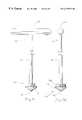
- FIG. 6 of the drawingsis a side elevation view of a bone burr according to the present invention.
- FIG. 7A of the drawingsis a top plan view of the bone burr according top the present invention.
- FIG. 7B of the drawingsis a bottom plan view of a bone burr according to the present invention.
- FIG. 8A of the drawingsis a side elevation view of a T-handle and bone burr assembly according to the present invention.
- FIG. 8B of the drawingsis another side elevation view of a T-handle and bone burr assembly according to the present invention.
- FIG. 9 of the drawingsis a side elevation view of an alternative embodiment power instrument adapter which can be used with the bone burr of the present invention.
- a bone fusion apparatus 10can be used to position bones in a desired area relative to one another and fuse the bones wherein the bones involved can be a variety of bones, such as wrist bones for example.
- Bone fusion apparatus 10is suitable for positioning and fusing a variety of bones in a variety of different anatomical locations.
- bone fusion apparatus 10can be used for fusing wrist bones, foot bones, cranial-facial bones, or other bones suitable for bone fusion.
- Bone fusion apparatus 10is particularly suitable for fusing wrist bones, even in a partial or limited manner as described herein without attachment to the radius bone or to a metacarpal bone. It is envisioned according to this invention of course that bone fusion apparatus 10 can be utilized for wrist fusion by attachment to the radius bone and/or by attachment to one or more metacarpal bones.
- plate Pcan be attached to a plurality of carpus area bones for utilization in fusing wrist as can be appreciated by those of skill in the art.
- Partial or limited wrist fusionas used herein, as discussed above and as can be appreciated by those of skill in the art, means fusion of carpus area bones only without fusion, affixation or attachment to the radius or to a metacarpal.
- bone fusion apparatus 10in a preferred embodiment comprises an annular, cone-shaped plate P which can be constructed of any suitable material for purposes as taught herein, but in a preferred embodiment is constructed of stainless steel, a bioabsorbable (resorbable) material, or other suitable material of construction as can be appreciated by those of skill in the art.
- Plate Pis suitably anatomically designed and adapted for positioning over any suitable bones for bone fusion. It is envisioned according to the present invention that the particular shape of plate P can vary within the scope of this invention. More specifically, plate P can be of a rounded circular, oval or elliptical or even of any other suitable outermost shape.
- plate Pis shown in a preferred position for utilization in limited wrist bone fusion as plate P is positioned over a plurality of carpus area bones. More specifically, plate P is shown positioned over a plurality of carpus area bones which as shown in FIG. 1A of the drawings comprise a lunate L, a triquetrium T, a hamate H, and a capitate C. While FIG. 1A of the drawings illustrates a preferred position of plate P for utilization in limited wrist fusion, it is specifically envisioned in accordance with this invention that plate P can be positioned over or proximate a radius bone and/or one or more metacarpal bones as desired for any type of wrist fusion as appropriate. Bones of other suitable, non-wrist areas as desirable and as mentioned previously, such as, for example, foot bones or cranial-facial bones, can also be utilized in association with plate P.
- annular plate Pis preferably at least substantially conical in shape and has an outer side OS, best illustrated in FIGS. 3, 4 and 5 , for at least partially contacting bone and an opposite, concave shaped inner side IS, best illustrated in FIGS. 1A, 1 B, 2 , and 5 .
- Plate Phas an outer circumferential edge 20 of greatest diameter and a smaller diameter, inner circumferential edge 30 which defines an at least substantially central opening 40 through plate P.
- the conical shape of plate Pis such that plate P tapers outwardly from inner edge 30 to outer edge 20 wherein plate P defines a plurality of holes therethrough between inner edge 30 and outer edge 20 .
- the holesare equally spaced-apart and of equal size as a preferred embodiment of plate P comprises holes H 1 -H 8 .
- holes H 1 -H 8are countersunk on inner side IS and each hole H 1 -H 8 is adapted for receiving a bone fastener for attaching plate P to a plurality of proximate or underlying bones, such as underlying carpus area bones when involved in limited wrist fusion.
- Holes H 1 -H 8therefore are of a larger diameter on inner side IS than on outer side OS of plate P.
- FIG. 5shows outer side OS of plate P disposed along line L 2 for illustration purposes in its cross-sectional view wherein line L 1 and line L 2 form angle A on the outer side OS of plate P.
- plate P in a preferred embodimenthas a height from central opening 40 to top outer edge 20 of approximately 0.152 inch, a bottom inner edge 30 circumferential width of approximately 0.251 inch, and a top outer edge 20 circumferential width of approximately 0.643 inch.
- Bone burr 100preferably is at least generally cone-shaped and includes burr teeth 110 on the outside thereon adapted for burring away bone. While it is envisioned according to this invention that bone burr 100 can be constructed of any suitable material for burring away bone, bone burr 100 most preferably is constructed of stainless steel. Bone burr 100 preferably forms a point 120 which is sharp and adapted for burring directly into bone.
- bone burr 100at least generally match that of plate P such that bone burr 100 can be easily used to burr away bone in a desired area, such as, for example, the carpus area or another suitable area wherein plate P can subsequently be very easily precisely placed in the burred away location and affixed there in position according to this invention with minimal or no sliding or slipping movement of plate P as it is affixed in position.
- a desired areasuch as, for example, the carpus area or another suitable area wherein plate P can subsequently be very easily precisely placed in the burred away location and affixed there in position according to this invention with minimal or no sliding or slipping movement of plate P as it is affixed in position.
- bone burr 100defines a threaded opening 130 in the top center portion of bone burr 100 , as best illustrated in FIG. 7 A. Opening 130 is adapted for matingly receiving a handle or an attachment or adapter for a power instrument.
- the handle for manual placement of bone burr 100can be a “t”-handle generally designated 150 , illustrated in FIGS. 8A and 8B of the drawings. “t”-handle 150 is preferably constructed of stainless steel and includes a “t”-shaped handle portion 160 attached perpendicularly to the top of a shaft portion 170 .
- Shaft portion 170includes a threaded bottom end 180 adapted for matingly engaging with and into opening 130 of bone burr 100 in a secure manner so that rotation of “t”-handle 150 likewise rotates bone burr 100 . It is also envisioned according to this invention that “t”-handle 150 and bone burr 100 could be integrally connected and formed as one unit.
- FIG. 9 of the drawingsillustrates the attachment or adapter for a power instrument as quick coupling adapter or device QC is shown.
- Quick coupling device QCcan be of any suitable construction and material and also preferably includes an end which can matingly engage with and into opening 130 of bone burr 100 in a secure manner so that rotation of quick coupling device QC likewise rotates bone burr 100 .
- Quick coupling device QC as shown in a preferred embodiment in FIG. 9 of the drawingscomprises an elongated shaft portion 200 with a bottom threaded end 210 for matingly engaging opening 130 of bone burr 100 .
- the opposite end 220 of quick coupling device QCcan be adapted for fitting with or into a power instrument such as a drill whereby the power instrument can be used to rotate quick coupling device QC, which in turn can rotate bone burr 100 simultaneously when quick coupling device QC is attached to bone burr 100 by fitting into opening 130 .
- End 220can be suitably shaped for fitting with or into a power instrument and can in one embodiment as shown in FIG. 9 comprise a notch 230 around outer shaft portion 200 .
- End 220can also include a flat side portion 240 as shown in FIG. 9 .
- Bone fusion apparatus 10according to the present invention and as described above can be utilized effectively and easily for positioning bones in a desired area relative to one another and for bone fusion for a variety of bones in different locations as described herein and as can readily be appreciated by those of skill in the art.
- a limited wrist fusion plateis generally indicated in patients with osteoarthritis or post-traumatic wrist arthritis, conditions involving significant loss of bone substance, rheumatoid arthritis, and failed partial wrist arthrodesis. Wrist arthrodesis can also be successfully utilized in patients with carpal instability.
- a preferred method of utilizing bone fusion apparatus 10can comprise what can be referred to as a method for four-corner limited arthrodesis.
- a longitudinal incision of approximately 7 cmis made centered over the dorsal wrist.
- a traverse incision of approximately 6 cmcan be utilized. Dissection is carried down through the subcutaneous tissues taking care to protect the sensory branch of the radial and ulnar nerve fibers.
- a separate longitudinal incisioncan be made between the fourth and fifth compartments which provides direct exposure to the four-bone region, and this technique is also utilized in patients who undergo a four-corner fusion for instability alone where the scaphoid does not require excision.
- any instability rotation of any of the four bonesis reduced and temporary percutaneous Kirschner wire fixation can be accomplished keeping the K-wires as volar as possible within the four bones.
- a small rongeurcan be used to denude cartilage between the four bones down through subchrondral bone to good cancellous bone.
- Bone burr 100can then be centered over the four bone corner junction, or in any other suitable desired location, and used to burr or rasp bone down flush with the dorsal aspect of the carpus which preferably exactly complements the configuration of the bottom of plate P. This technique allows excellent exposure to good cancellous bone in the four-corner region prior to plate placement.
- burring of bone with bone burr 100can be accomplished by grasping and rotating “t”-handle 150 (or quick connect QC) while forcing it downward.
- Autogenous cancellous bone graft taken from either the excised scaphoid or Lister's tubercle in the distal radiuscan then be packed between each of the joint surfaces and in the junction of the four-corner fusion at the bottom of the rasped defect.
- plate Pis then aligned to allow maximum screw placement in each of the four bones.
- at least one, and preferably two, screwscan be placed within each of the four bones through the fastener holes H 1 -H 8 of plate P.
- a suitable drill bitsuch as a 1.5 mm drill bit, can be used to place one bone screw in each of the four bones.
- the screws utilizedcan be of any suitable type and size, and preferably can be 10 mm long or 14 mm long, 2.4 mm diameter cancellous self-tapping screws to fix plate P down in position.
- the screwsare preferably placed in a tightened fashion to allow radial or lateral compression of the bones rather to urge the bones toward one another and desirably facilitate bone fusion.
- the remaining appropriate fastener holescan be drilled and further screws placed of appropriate length to allow excellent position and yet to avoid protrusion through articular surfaces.
- FIG. 1B of the drawingsillustrates plate P fixed in a preferred position for limited wrist fusion with fasteners F shown as bone screws fixed to the underlying bones, which are carpal area bones, through holes H 1 -H 8 .
- fasteners Fshown as bone screws fixed to the underlying bones, which are carpal area bones, through holes H 1 -H 8 .
- Intraoperative fluoroscopic and standard AP and lateral radiographscan be undertaken to ensure appropriate plate P placement and screw fixation. Range of motion testing can be undertaken to ensure excellent stability of the fusion plate. Additional bone graft can be packed within the center portion of the four-corner region through plate P itself without difficulty.
- Irrigation and debridement of the woundis undertaken, and sequential repair of the capsule and retinacular structures are undertaken using suitable (#4-0) absorbable sutures.
- a short-arm light bulky splintis placed allowing early active finger range of motion.
- a removable splintcan be placed to allow early range of motion exercises or alternatively, a short-arm cast can be placed for three to four weeks of protection.
- Radiographsshould be taken on a sequential basis to ensure appropriate fusion of the four-corner region prior to allowing return to normal activities.
- bone fusion apparatus 10can be positioned over and affixed precisely in position against a variety of bones in a variety of anatomical locations, such as, for example, against foot bones, cranial-facial bones, or any other suitable bones in addition to use with wrist bones for total bone fusion or for limited bone fusion as described herein.
- Bone burr 100can be used with any suitable bones of any suitable location in a fashion as described with the wrist bones above in order to advantageously provide a precise location in which bone fusion apparatus 10 can at least partially be fitted during affixation.
- Fixation of plate P in position as described abovetherefore can, unlike prior art apparatuses and methods for bone positioning and fusion, quite advantageously provide radial compression of bones to be positioned and/or fused wherein the bones are drawn and urged toward one another and toward a vertical axis disposed through plate P at least generally perpendicular to the plane represented by line L 1 .
- Fixation of plate P in position as described abovealso provides desirable stability so as to allow the bones beneath and to which plate P is affixed to fuse properly.
- plate P for wrist fusionis believed to eliminate complications which can typically occur with the use of conventional bone fusion apparatuses such as wrist fusion plates for limited wrist fusion as primarily for patients with post-traumatic or osteoarthritis.
- the plateis countersunk into the bones being fusion decreasing any contact between the plate and overlying soft tissues and tendons.
- the plateallows bone graft to be placed even after fixation at the fusion site.
- the plate and screwsform a three axis fixation of the bones being fused with circumferential compression and compression of the plate to the bones.
- the plateallows screw placement at an oblique angle to the main plane of the plate providing the aforementioned advantages.
- bone fusion apparatus 10can be used simply to position one or more bones relative to one or more other bones or structures regardless of whether fusion of the associated bones is desired.
- the present inventionprovides a novel bone fusion apparatus and method for attaching to a variety of bones for bone fusion. It can also be seen that the present invention provides a bone fusion apparatus and method particularly suitable for utilization in fusing wrist bones with or without attachment to the radius bone or to a metacarpal bone. Finally, it can be understood that the present invention provides a bone fusion apparatus and method wherein the bone fusion apparatus can effectively and easily be positioned and affixed precisely in place and can be effectively and easily utilized for bone fusion with a unique three dimensional fixation method.
Landscapes
- Health & Medical Sciences (AREA)
- Surgery (AREA)
- Orthopedic Medicine & Surgery (AREA)
- Life Sciences & Earth Sciences (AREA)
- Heart & Thoracic Surgery (AREA)
- Veterinary Medicine (AREA)
- Engineering & Computer Science (AREA)
- Biomedical Technology (AREA)
- Nuclear Medicine, Radiotherapy & Molecular Imaging (AREA)
- Medical Informatics (AREA)
- Molecular Biology (AREA)
- Animal Behavior & Ethology (AREA)
- General Health & Medical Sciences (AREA)
- Public Health (AREA)
- Dentistry (AREA)
- Oral & Maxillofacial Surgery (AREA)
- Neurology (AREA)
- Surgical Instruments (AREA)
Abstract
Description
Claims (19)
Priority Applications (3)
| Application Number | Priority Date | Filing Date | Title |
|---|---|---|---|
| US09/399,021US6179839B1 (en) | 1999-09-20 | 1999-09-20 | Bone fusion apparatus and method |
| AU38849/01AAU3884901A (en) | 1999-09-20 | 2000-09-20 | Bone fusion apparatus and method |
| PCT/US2000/025810WO2001021083A1 (en) | 1999-09-20 | 2000-09-20 | Bone fusion apparatus and method |
Applications Claiming Priority (1)
| Application Number | Priority Date | Filing Date | Title |
|---|---|---|---|
| US09/399,021US6179839B1 (en) | 1999-09-20 | 1999-09-20 | Bone fusion apparatus and method |
Publications (1)
| Publication Number | Publication Date |
|---|---|
| US6179839B1true US6179839B1 (en) | 2001-01-30 |
Family
ID=23577802
Family Applications (1)
| Application Number | Title | Priority Date | Filing Date |
|---|---|---|---|
| US09/399,021Expired - LifetimeUS6179839B1 (en) | 1999-09-20 | 1999-09-20 | Bone fusion apparatus and method |
Country Status (3)
| Country | Link |
|---|---|
| US (1) | US6179839B1 (en) |
| AU (1) | AU3884901A (en) |
| WO (1) | WO2001021083A1 (en) |
Cited By (92)
| Publication number | Priority date | Publication date | Assignee | Title |
|---|---|---|---|---|
| USD450122S1 (en) | 2000-01-03 | 2001-11-06 | Gary K. Michelson | End cap for a spinal implant |
| US20030188574A1 (en)* | 2002-04-04 | 2003-10-09 | Weiss Arnold A. | Apparatus and method for electronic tire testing |
| US20040016293A1 (en)* | 2002-04-05 | 2004-01-29 | Weiss Arnold A. | Apparatus and method for tire testing |
| WO2004008980A1 (en)* | 2002-07-22 | 2004-01-29 | Acumed Llc | Bone fusion system |
| US20040102778A1 (en)* | 2002-11-19 | 2004-05-27 | Huebner Randall J. | Adjustable bone plates |
| US20040102788A1 (en)* | 2002-11-19 | 2004-05-27 | Huebner Randall J. | Guide system for bone-repair devices |
| US20040116930A1 (en)* | 2002-06-10 | 2004-06-17 | O'driscoll Shawn W. | Bone plates |
| US6755834B2 (en)* | 2000-09-15 | 2004-06-29 | Medtronic, Inc. | Cranial flap fixation device |
| USD493533S1 (en) | 2003-02-14 | 2004-07-27 | Nuvasive, Inc. | Intervertebral implant |
| US20040260291A1 (en)* | 2003-06-20 | 2004-12-23 | Jensen David G. | Bone plates with intraoperatively tapped apertures |
| US20050085819A1 (en)* | 2003-08-28 | 2005-04-21 | Ellis Thomas J. | Bone plates |
| US20050131413A1 (en)* | 2003-06-20 | 2005-06-16 | O'driscoll Shawn W. | Bone plate with interference fit screw |
| US20050171544A1 (en)* | 2004-02-02 | 2005-08-04 | Acumed Llc | Bone plate with toothed aperture |
| US20050228389A1 (en)* | 2002-05-23 | 2005-10-13 | Claes-Olof Stiernborg | Mitre instrument, as an example for hallux surgery |
| US20050228386A1 (en)* | 2004-04-08 | 2005-10-13 | Tara Ziolo | Bone fixation device |
| US20050234472A1 (en)* | 2004-04-19 | 2005-10-20 | Huebner Randall J | Placement of fasteners into bone |
| US20050234458A1 (en)* | 2004-04-19 | 2005-10-20 | Huebner Randall J | Expanded stabilization of bones |
| US20050240187A1 (en)* | 2004-04-22 | 2005-10-27 | Huebner Randall J | Expanded fixation of bones |
| US20060025772A1 (en)* | 2004-07-30 | 2006-02-02 | Leibel David A | Bone fusion plate |
| US20060149249A1 (en)* | 2002-12-11 | 2006-07-06 | Christophe Mathoulin | Osteosynthesis plate for the osteosynthesis of small neighbouring bones |
| US20060149251A1 (en)* | 2004-12-22 | 2006-07-06 | Tara Ziolo | Bone fixation system |
| US20060264951A1 (en)* | 2005-05-18 | 2006-11-23 | Nelson Charles L | Minimally Invasive Actuable Bone Fixation Devices Having a Retractable Interdigitation Process |
| US20060276795A1 (en)* | 2005-06-02 | 2006-12-07 | Orbay Jorge L | Scapholunate Disassociation Repair System |
| US20070055249A1 (en)* | 2003-06-20 | 2007-03-08 | Jensen David G | Bone plates with intraoperatively tapped apertures |
| US7189237B2 (en) | 2002-11-19 | 2007-03-13 | Acumed Llc | Deformable bone plates |
| US20070083207A1 (en)* | 2005-09-21 | 2007-04-12 | Tara Ziolo | Variable angle bone fixation assembly |
| US20070135917A1 (en)* | 2005-10-26 | 2007-06-14 | Malinin Theodore I | Instrumentation for the preparation and transplantation of osteochondral allografts |
| US20070162018A1 (en)* | 2002-07-22 | 2007-07-12 | Jensen David G | Orthopedic systems |
| US20080132896A1 (en)* | 2006-11-22 | 2008-06-05 | Sonoma Orthopedic Products, Inc. | Curved orthopedic tool |
| US20080140078A1 (en)* | 2006-11-22 | 2008-06-12 | Sonoma Orthopedic Products, Inc. | Surgical tools for use in deploying bone repair devices |
| US20080149115A1 (en)* | 2006-11-22 | 2008-06-26 | Sonoma Orthopedic Products, Inc. | Surgical station for orthopedic reconstruction surgery |
| US20080160084A1 (en)* | 2004-12-22 | 2008-07-03 | Colarome, Inc. | Natural Water-Insoluble Encapsulation Compositions and Processes for Preparing Same |
| US20080161805A1 (en)* | 2006-11-22 | 2008-07-03 | Sonoma Orthopedic Products, Inc. | Fracture fixation device, tools and methods |
| US20090018588A1 (en)* | 2006-12-19 | 2009-01-15 | Stephan Eckhof | Orthopedic screw fastener system |
| DE202008017034U1 (en) | 2008-12-30 | 2009-03-05 | Medartis Ag | Arthrodeseplatte |
| US20090069812A1 (en)* | 2007-06-15 | 2009-03-12 | Acumed Llc | Rib fixation with an intramedullary nail |
| US20090093853A1 (en)* | 2007-10-05 | 2009-04-09 | Biomet Manufacturing Corp. | System For Forming A Tendon-Bone Graft |
| US7527649B1 (en) | 2002-02-15 | 2009-05-05 | Nuvasive, Inc. | Intervertebral implant and related methods |
| US7537604B2 (en) | 2002-11-19 | 2009-05-26 | Acumed Llc | Bone plates with slots |
| DE202009001900U1 (en) | 2009-02-23 | 2009-07-16 | Zrinski Ag | Implant for fusion of bones or bone parts |
| US20090222052A1 (en)* | 2007-10-05 | 2009-09-03 | Biomet Manufacturing Corp. | System For Forming A Tendon-Bone Graft |
| US20110040301A1 (en)* | 2007-02-22 | 2011-02-17 | Spinal Elements, Inc. | Vertebral facet joint drill and method of use |
| US20110082503A1 (en)* | 2004-02-06 | 2011-04-07 | Spinal Elements, Inc. | Vertebral facet joint prosthesis and method of fixation |
| US20110087295A1 (en)* | 2009-10-12 | 2011-04-14 | University Of Utah | Bone fixation systems |
| US20110093018A1 (en)* | 2009-10-15 | 2011-04-21 | Priya Prasad | Dorsal midfoot bone plate system and method |
| US20110306981A1 (en)* | 2009-05-04 | 2011-12-15 | Je-Won Wang | Unitary alveolar bone chisel and spreader osteotome for a dental implant |
| US20120197261A1 (en)* | 2011-01-28 | 2012-08-02 | Mirko Rocci | Reamer guide systems and methods of use |
| US8287539B2 (en) | 2005-05-18 | 2012-10-16 | Sonoma Orthopedic Products, Inc. | Fracture fixation device, tools and methods |
| US8568417B2 (en) | 2009-12-18 | 2013-10-29 | Charles River Engineering Solutions And Technologies, Llc | Articulating tool and methods of using |
| US20130304224A1 (en)* | 2012-05-08 | 2013-11-14 | Trimed, Inc. | Implant for fixation of first and second bones and method of fixing first and second bones using the implant |
| US8657820B2 (en) | 2009-10-12 | 2014-02-25 | Tornier, Inc. | Bone plate and keel systems |
| US8961516B2 (en) | 2005-05-18 | 2015-02-24 | Sonoma Orthopedic Products, Inc. | Straight intramedullary fracture fixation devices and methods |
| USD724733S1 (en)* | 2011-02-24 | 2015-03-17 | Spinal Elements, Inc. | Interbody bone implant |
| US9060820B2 (en) | 2005-05-18 | 2015-06-23 | Sonoma Orthopedic Products, Inc. | Segmented intramedullary fracture fixation devices and methods |
| US9060787B2 (en) | 2007-02-22 | 2015-06-23 | Spinal Elements, Inc. | Method of using a vertebral facet joint drill |
| USD739935S1 (en)* | 2011-10-26 | 2015-09-29 | Spinal Elements, Inc. | Interbody bone implant |
| US9155574B2 (en) | 2006-05-17 | 2015-10-13 | Sonoma Orthopedic Products, Inc. | Bone fixation device, tools and methods |
| US9179943B2 (en) | 2011-02-24 | 2015-11-10 | Spinal Elements, Inc. | Methods and apparatus for stabilizing bone |
| US9237910B2 (en) | 2012-01-26 | 2016-01-19 | Acute Innovations Llc | Clip for rib stabilization |
| US9271765B2 (en) | 2011-02-24 | 2016-03-01 | Spinal Elements, Inc. | Vertebral facet joint fusion implant and method for fusion |
| US9370387B2 (en) | 2009-10-15 | 2016-06-21 | Biomet C.V. | Bending tool and method for reshaping a bone plate |
| US9421044B2 (en) | 2013-03-14 | 2016-08-23 | Spinal Elements, Inc. | Apparatus for bone stabilization and distraction and methods of use |
| USD765853S1 (en) | 2013-03-14 | 2016-09-06 | Spinal Elements, Inc. | Flexible elongate member with a portion configured to receive a bone anchor |
| US9456855B2 (en) | 2013-09-27 | 2016-10-04 | Spinal Elements, Inc. | Method of placing an implant between bone portions |
| US9468479B2 (en) | 2013-09-06 | 2016-10-18 | Cardinal Health 247, Inc. | Bone plate |
| US9744042B2 (en)* | 2009-09-24 | 2017-08-29 | Academish Ziekenhuis Maastricht; Universiteit Maastricht | Cranial implant |
| US9770278B2 (en) | 2014-01-17 | 2017-09-26 | Arthrex, Inc. | Dual tip guide wire |
| US9775657B2 (en) | 2011-09-30 | 2017-10-03 | Acute Innovations Llc | Bone fixation system with opposed mounting portions |
| US20170311957A1 (en)* | 2016-04-28 | 2017-11-02 | David K. Boger | Oscillating decortication burr assembly |
| US9814499B2 (en) | 2014-09-30 | 2017-11-14 | Arthrex, Inc. | Intramedullary fracture fixation devices and methods |
| US9820784B2 (en) | 2013-03-14 | 2017-11-21 | Spinal Elements, Inc. | Apparatus for spinal fixation and methods of use |
| US9839450B2 (en) | 2013-09-27 | 2017-12-12 | Spinal Elements, Inc. | Device and method for reinforcement of a facet |
| US9931142B2 (en) | 2004-06-10 | 2018-04-03 | Spinal Elements, Inc. | Implant and method for facet immobilization |
| US9956015B2 (en) | 2014-07-03 | 2018-05-01 | Acumed Llc | Bone plate with movable joint |
| US10265174B2 (en) | 2014-07-24 | 2019-04-23 | Xilloc Medical B.V. | Implant with suture anchors and method |
| US10357260B2 (en) | 2015-11-02 | 2019-07-23 | First Ray, LLC | Orthopedic fastener, retainer, and guide methods |
| US10376367B2 (en) | 2015-07-02 | 2019-08-13 | First Ray, LLC | Orthopedic fasteners, instruments and methods |
| US20200038195A1 (en)* | 2018-08-06 | 2020-02-06 | Baylor University | Carpal bone fusion device and method |
| US10653468B2 (en)* | 2016-08-29 | 2020-05-19 | Osteomed Llc | Four corner fusion device |
| US10758361B2 (en) | 2015-01-27 | 2020-09-01 | Spinal Elements, Inc. | Facet joint implant |
| US20210244542A1 (en)* | 2020-02-07 | 2021-08-12 | Trimed, Incorporated | Implant for fusing at least two bone components and method of fusing bone components using the implant |
| US11304733B2 (en) | 2020-02-14 | 2022-04-19 | Spinal Elements, Inc. | Bone tie methods |
| US20220240952A1 (en)* | 2016-04-28 | 2022-08-04 | David K. Boger | Oscillating decortication burr assembly |
| US11457959B2 (en) | 2019-05-22 | 2022-10-04 | Spinal Elements, Inc. | Bone tie and bone tie inserter |
| US11464552B2 (en) | 2019-05-22 | 2022-10-11 | Spinal Elements, Inc. | Bone tie and bone tie inserter |
| US11478275B2 (en) | 2014-09-17 | 2022-10-25 | Spinal Elements, Inc. | Flexible fastening band connector |
| US20220378483A1 (en)* | 2016-10-20 | 2022-12-01 | Tianjin Zhengtian Medical Instrument Co., Ltd | Bidirectional fixation steel plate and a bone shaft fixation system |
| US11678875B2 (en) | 2021-04-27 | 2023-06-20 | DePuy Synthes Products, Inc. | Methods and apparatus for radially compressive shape memory implants |
| EP4146104A4 (en)* | 2020-05-07 | 2024-06-19 | ExsoMed Corporation | WRIST FUSION SYSTEM AND RELEASE INSTRUMENT |
| US12285197B2 (en) | 2008-10-10 | 2025-04-29 | Acumed Llc | Bone fixation system with opposed mounting portions |
| US12369952B2 (en) | 2021-12-10 | 2025-07-29 | Spinal Elements, Inc. | Bone tie and portal |
| US12440242B2 (en) | 2024-04-29 | 2025-10-14 | Spinal Elements, Inc. | Flexible fastening band connector |
Citations (3)
| Publication number | Priority date | Publication date | Assignee | Title |
|---|---|---|---|---|
| US3939497A (en)* | 1973-12-28 | 1976-02-24 | Friedrichsfeld Gmbh. Steinzeug-Und Kunststoffwerke | Fastening means for hip joint prosthesis sockets |
| US5314490A (en)* | 1992-04-03 | 1994-05-24 | Sulzer Medizinaltechnik Ag | Outer cup for an artificial hipjoint socket |
| US5919195A (en)* | 1998-01-20 | 1999-07-06 | Johnson & Johnson Professional, Inc. | Oblong acetabular component instrumentation |
- 1999
- 1999-09-20USUS09/399,021patent/US6179839B1/ennot_activeExpired - Lifetime
- 2000
- 2000-09-20AUAU38849/01Apatent/AU3884901A/ennot_activeAbandoned
- 2000-09-20WOPCT/US2000/025810patent/WO2001021083A1/enactiveApplication Filing
Patent Citations (3)
| Publication number | Priority date | Publication date | Assignee | Title |
|---|---|---|---|---|
| US3939497A (en)* | 1973-12-28 | 1976-02-24 | Friedrichsfeld Gmbh. Steinzeug-Und Kunststoffwerke | Fastening means for hip joint prosthesis sockets |
| US5314490A (en)* | 1992-04-03 | 1994-05-24 | Sulzer Medizinaltechnik Ag | Outer cup for an artificial hipjoint socket |
| US5919195A (en)* | 1998-01-20 | 1999-07-06 | Johnson & Johnson Professional, Inc. | Oblong acetabular component instrumentation |
Cited By (214)
| Publication number | Priority date | Publication date | Assignee | Title |
|---|---|---|---|---|
| USD450122S1 (en) | 2000-01-03 | 2001-11-06 | Gary K. Michelson | End cap for a spinal implant |
| USD454953S1 (en) | 2000-01-03 | 2002-03-26 | Gary K. Michelson | End cap for a spinal implant |
| USD460188S1 (en) | 2000-01-03 | 2002-07-09 | Gary K. Michelson | End cap for a spinal implant |
| USD463560S1 (en) | 2000-01-03 | 2002-09-24 | Gary K. Michelson | End cap for a spinal implant |
| US20040210225A1 (en)* | 2000-09-15 | 2004-10-21 | Amis James Peter | Cranial flap fixation device |
| US6755834B2 (en)* | 2000-09-15 | 2004-06-29 | Medtronic, Inc. | Cranial flap fixation device |
| US7527649B1 (en) | 2002-02-15 | 2009-05-05 | Nuvasive, Inc. | Intervertebral implant and related methods |
| US20030188574A1 (en)* | 2002-04-04 | 2003-10-09 | Weiss Arnold A. | Apparatus and method for electronic tire testing |
| US6907777B2 (en)* | 2002-04-04 | 2005-06-21 | Arnold A. Weiss | Apparatus and method for electronic tire testing |
| US20040016293A1 (en)* | 2002-04-05 | 2004-01-29 | Weiss Arnold A. | Apparatus and method for tire testing |
| US6832513B2 (en)* | 2002-04-05 | 2004-12-21 | Arnold A. Weiss | Apparatus and method for tire testing |
| US7572258B2 (en)* | 2002-05-23 | 2009-08-11 | Claes-Olof Stiernborg | Mitre instrument, as an example for hallux surgery |
| US20050228389A1 (en)* | 2002-05-23 | 2005-10-13 | Claes-Olof Stiernborg | Mitre instrument, as an example for hallux surgery |
| US20040116930A1 (en)* | 2002-06-10 | 2004-06-17 | O'driscoll Shawn W. | Bone plates |
| US20110137351A1 (en)* | 2002-07-22 | 2011-06-09 | Acumed Llc | Bone fixation with a bone plate attached to a fastener assembly |
| US7537603B2 (en) | 2002-07-22 | 2009-05-26 | Acumed Llc | Bone fusion system |
| US8425574B2 (en) | 2002-07-22 | 2013-04-23 | Acumed, Llc | Bone fixation with a bone plate attached to a fastener assembly |
| GB2407510A (en)* | 2002-07-22 | 2005-05-04 | Acumed Llc | Bone fusion system |
| AU2003261221B2 (en)* | 2002-07-22 | 2007-05-17 | Acumed Llc | Bone fusion system |
| US10456180B2 (en) | 2002-07-22 | 2019-10-29 | Acumed Llc | Adjustable bone plates |
| KR101081268B1 (en) | 2002-07-22 | 2011-11-08 | 어큠드 엘엘씨 | Bone fusion system |
| US20040127901A1 (en)* | 2002-07-22 | 2004-07-01 | Huebner Randall J. | Bone fusion system |
| US20070162018A1 (en)* | 2002-07-22 | 2007-07-12 | Jensen David G | Orthopedic systems |
| US7717945B2 (en) | 2002-07-22 | 2010-05-18 | Acumed Llc | Orthopedic systems |
| CN1309352C (en)* | 2002-07-22 | 2007-04-11 | 精密医疗责任有限公司 | Bone fusion system |
| WO2004008980A1 (en)* | 2002-07-22 | 2004-01-29 | Acumed Llc | Bone fusion system |
| JP2005533565A (en)* | 2002-07-22 | 2005-11-10 | アキュームド・エルエルシー | Bone fixation system |
| US9308033B2 (en) | 2002-07-22 | 2016-04-12 | Acumed Llc | Adjustable bone plates |
| GB2407510B (en)* | 2002-07-22 | 2006-06-28 | Acumed Llc | Bone fusion system |
| US7153309B2 (en) | 2002-11-19 | 2006-12-26 | Acumed Llc | Guide system for bone-repair devices |
| US7704251B2 (en) | 2002-11-19 | 2010-04-27 | Acumed Llc | Adjustable bone plates |
| US7090676B2 (en) | 2002-11-19 | 2006-08-15 | Acumed Llc | Adjustable bone plates |
| US20070276405A1 (en)* | 2002-11-19 | 2007-11-29 | Huebner Randall J | Adjustable bone plates |
| US7537604B2 (en) | 2002-11-19 | 2009-05-26 | Acumed Llc | Bone plates with slots |
| US20040102778A1 (en)* | 2002-11-19 | 2004-05-27 | Huebner Randall J. | Adjustable bone plates |
| US20040102788A1 (en)* | 2002-11-19 | 2004-05-27 | Huebner Randall J. | Guide system for bone-repair devices |
| US7326212B2 (en) | 2002-11-19 | 2008-02-05 | Acumed Llc | Bone plates with reference marks |
| US7189237B2 (en) | 2002-11-19 | 2007-03-13 | Acumed Llc | Deformable bone plates |
| US20060149249A1 (en)* | 2002-12-11 | 2006-07-06 | Christophe Mathoulin | Osteosynthesis plate for the osteosynthesis of small neighbouring bones |
| USD493533S1 (en) | 2003-02-14 | 2004-07-27 | Nuvasive, Inc. | Intervertebral implant |
| US20070055249A1 (en)* | 2003-06-20 | 2007-03-08 | Jensen David G | Bone plates with intraoperatively tapped apertures |
| US7537596B2 (en) | 2003-06-20 | 2009-05-26 | Acumed Llc | Bone plates with intraoperatively tapped apertures |
| US20050131413A1 (en)* | 2003-06-20 | 2005-06-16 | O'driscoll Shawn W. | Bone plate with interference fit screw |
| US20040260291A1 (en)* | 2003-06-20 | 2004-12-23 | Jensen David G. | Bone plates with intraoperatively tapped apertures |
| US7635365B2 (en) | 2003-08-28 | 2009-12-22 | Ellis Thomas J | Bone plates |
| US7695501B2 (en) | 2003-08-28 | 2010-04-13 | Ellis Thomas J | Bone fixation system |
| US20050085819A1 (en)* | 2003-08-28 | 2005-04-21 | Ellis Thomas J. | Bone plates |
| US8632573B2 (en) | 2003-08-28 | 2014-01-21 | Thomas J. Ellis | Bone fixation system |
| US20050171544A1 (en)* | 2004-02-02 | 2005-08-04 | Acumed Llc | Bone plate with toothed aperture |
| US9675387B2 (en) | 2004-02-06 | 2017-06-13 | Spinal Elements, Inc. | Vertebral facet joint prosthesis and method of fixation |
| US8858597B2 (en) | 2004-02-06 | 2014-10-14 | Spinal Elements, Inc. | Vertebral facet joint prosthesis and method of fixation |
| US10085776B2 (en) | 2004-02-06 | 2018-10-02 | Spinal Elements, Inc. | Vertebral facet joint prosthesis and method of fixation |
| US8998953B2 (en) | 2004-02-06 | 2015-04-07 | Spinal Elements, Inc. | Vertebral facet joint prosthesis and method of fixation |
| US20110082503A1 (en)* | 2004-02-06 | 2011-04-07 | Spinal Elements, Inc. | Vertebral facet joint prosthesis and method of fixation |
| US8882804B2 (en) | 2004-02-06 | 2014-11-11 | Spinal Elements, Inc. | Vertebral facet joint prosthesis and method of fixation |
| US20050228386A1 (en)* | 2004-04-08 | 2005-10-13 | Tara Ziolo | Bone fixation device |
| US8828064B2 (en) | 2004-04-08 | 2014-09-09 | Ebi, Llc | Bone fixation device |
| US7942913B2 (en) | 2004-04-08 | 2011-05-17 | Ebi, Llc | Bone fixation device |
| US10010357B2 (en) | 2004-04-08 | 2018-07-03 | Zimmer Biomet Spine, Inc. | Bone fixation device |
| US20110196423A1 (en)* | 2004-04-08 | 2011-08-11 | Ebi, L.P. | Bone fixation device |
| US7578825B2 (en) | 2004-04-19 | 2009-08-25 | Acumed Llc | Placement of fasteners into bone |
| US20050234472A1 (en)* | 2004-04-19 | 2005-10-20 | Huebner Randall J | Placement of fasteners into bone |
| US20050234458A1 (en)* | 2004-04-19 | 2005-10-20 | Huebner Randall J | Expanded stabilization of bones |
| US20050240187A1 (en)* | 2004-04-22 | 2005-10-27 | Huebner Randall J | Expanded fixation of bones |
| US8177819B2 (en) | 2004-04-22 | 2012-05-15 | Acumed Llc | Expanded fixation of bones |
| US9931142B2 (en) | 2004-06-10 | 2018-04-03 | Spinal Elements, Inc. | Implant and method for facet immobilization |
| US20060025772A1 (en)* | 2004-07-30 | 2006-02-02 | Leibel David A | Bone fusion plate |
| US20080091198A1 (en)* | 2004-07-30 | 2008-04-17 | Mayo Foundation For Medical Research And Education | Bone Fusion Plate |
| US7887570B2 (en) | 2004-12-22 | 2011-02-15 | Ebi, Llc | Bone fixation system |
| US20090210014A1 (en)* | 2004-12-22 | 2009-08-20 | Ebi, Llc | Bone fixation system |
| US20080160084A1 (en)* | 2004-12-22 | 2008-07-03 | Colarome, Inc. | Natural Water-Insoluble Encapsulation Compositions and Processes for Preparing Same |
| US10981136B2 (en) | 2004-12-22 | 2021-04-20 | Capol Inc. | Natural water-insoluble encapsulation compositions and processes for preparing same |
| US9687807B2 (en) | 2004-12-22 | 2017-06-27 | Colarome, Inc. | Natural water-insoluble encapsulation compositions and processes for preparing same |
| US7527640B2 (en) | 2004-12-22 | 2009-05-05 | Ebi, Llc | Bone fixation system |
| US20060149251A1 (en)* | 2004-12-22 | 2006-07-06 | Tara Ziolo | Bone fixation system |
| US7846162B2 (en) | 2005-05-18 | 2010-12-07 | Sonoma Orthopedic Products, Inc. | Minimally invasive actuable bone fixation devices |
| US8961516B2 (en) | 2005-05-18 | 2015-02-24 | Sonoma Orthopedic Products, Inc. | Straight intramedullary fracture fixation devices and methods |
| US20060264950A1 (en)* | 2005-05-18 | 2006-11-23 | Nelson Charles L | Minimally Invasive Actuable Bone Fixation Devices |
| US7914533B2 (en) | 2005-05-18 | 2011-03-29 | Sonoma Orthopedic Products, Inc. | Minimally invasive actuable bone fixation devices |
| US20060264952A1 (en)* | 2005-05-18 | 2006-11-23 | Nelson Charles L | Methods of Using Minimally Invasive Actuable Bone Fixation Devices |
| US9060820B2 (en) | 2005-05-18 | 2015-06-23 | Sonoma Orthopedic Products, Inc. | Segmented intramedullary fracture fixation devices and methods |
| US20070233105A1 (en)* | 2005-05-18 | 2007-10-04 | Nelson Charles L | Minimally invasive actuable bone fixation devices |
| US20060264951A1 (en)* | 2005-05-18 | 2006-11-23 | Nelson Charles L | Minimally Invasive Actuable Bone Fixation Devices Having a Retractable Interdigitation Process |
| US8287541B2 (en) | 2005-05-18 | 2012-10-16 | Sonoma Orthopedic Products, Inc. | Fracture fixation device, tools and methods |
| US7942875B2 (en) | 2005-05-18 | 2011-05-17 | Sonoma Orthopedic Products, Inc. | Methods of using minimally invasive actuable bone fixation devices |
| US8287539B2 (en) | 2005-05-18 | 2012-10-16 | Sonoma Orthopedic Products, Inc. | Fracture fixation device, tools and methods |
| US20060276795A1 (en)* | 2005-06-02 | 2006-12-07 | Orbay Jorge L | Scapholunate Disassociation Repair System |
| US20070083207A1 (en)* | 2005-09-21 | 2007-04-12 | Tara Ziolo | Variable angle bone fixation assembly |
| US7955364B2 (en) | 2005-09-21 | 2011-06-07 | Ebi, Llc | Variable angle bone fixation assembly |
| US20070135917A1 (en)* | 2005-10-26 | 2007-06-14 | Malinin Theodore I | Instrumentation for the preparation and transplantation of osteochondral allografts |
| US8523864B2 (en)* | 2005-10-26 | 2013-09-03 | Biomet Sports Medicine, Llc | Instrumentation for the preparation and transplantation of osteochondral allografts |
| US8882774B2 (en) | 2005-10-26 | 2014-11-11 | Biomet Sports Medicine, Llc | Instrumentation for the preparation and transplantation of osteochondral allografts |
| US20070135918A1 (en)* | 2005-10-26 | 2007-06-14 | Malinin Theodore I | Instrumentation for the preparation and transplantation of osteochondral allografts |
| US9155574B2 (en) | 2006-05-17 | 2015-10-13 | Sonoma Orthopedic Products, Inc. | Bone fixation device, tools and methods |
| US20080161805A1 (en)* | 2006-11-22 | 2008-07-03 | Sonoma Orthopedic Products, Inc. | Fracture fixation device, tools and methods |
| US20110144645A1 (en)* | 2006-11-22 | 2011-06-16 | Sonoma Orthopedic Products, Inc. | Fracture Fixation Device, Tools and Methods |
| US9259250B2 (en) | 2006-11-22 | 2016-02-16 | Sonoma Orthopedic Products, Inc. | Fracture fixation device, tools and methods |
| US20080132896A1 (en)* | 2006-11-22 | 2008-06-05 | Sonoma Orthopedic Products, Inc. | Curved orthopedic tool |
| US8439917B2 (en) | 2006-11-22 | 2013-05-14 | Sonoma Orthopedic Products, Inc. | Fracture fixation device, tools and methods |
| US7909825B2 (en) | 2006-11-22 | 2011-03-22 | Sonoma Orthepedic Products, Inc. | Fracture fixation device, tools and methods |
| US20080140078A1 (en)* | 2006-11-22 | 2008-06-12 | Sonoma Orthopedic Products, Inc. | Surgical tools for use in deploying bone repair devices |
| US20080149115A1 (en)* | 2006-11-22 | 2008-06-26 | Sonoma Orthopedic Products, Inc. | Surgical station for orthopedic reconstruction surgery |
| US8506607B2 (en) | 2006-12-19 | 2013-08-13 | Zrinski Ag | Orthopedic screw fastener system |
| US20090018588A1 (en)* | 2006-12-19 | 2009-01-15 | Stephan Eckhof | Orthopedic screw fastener system |
| US9060787B2 (en) | 2007-02-22 | 2015-06-23 | Spinal Elements, Inc. | Method of using a vertebral facet joint drill |
| US9743937B2 (en) | 2007-02-22 | 2017-08-29 | Spinal Elements, Inc. | Vertebral facet joint drill and method of use |
| US9517077B2 (en) | 2007-02-22 | 2016-12-13 | Spinal Elements, Inc. | Vertebral facet joint drill and method of use |
| US8992533B2 (en) | 2007-02-22 | 2015-03-31 | Spinal Elements, Inc. | Vertebral facet joint drill and method of use |
| US20110040301A1 (en)* | 2007-02-22 | 2011-02-17 | Spinal Elements, Inc. | Vertebral facet joint drill and method of use |
| US20090069812A1 (en)* | 2007-06-15 | 2009-03-12 | Acumed Llc | Rib fixation with an intramedullary nail |
| US8322256B2 (en) | 2007-10-05 | 2012-12-04 | Biomet Manufacturing Corp. | System for forming a tendon-bone graft |
| US20090093853A1 (en)* | 2007-10-05 | 2009-04-09 | Biomet Manufacturing Corp. | System For Forming A Tendon-Bone Graft |
| US20090222052A1 (en)* | 2007-10-05 | 2009-09-03 | Biomet Manufacturing Corp. | System For Forming A Tendon-Bone Graft |
| US8303592B2 (en) | 2007-10-05 | 2012-11-06 | Biomet Manufacturing Corp. | System for forming a tendon-bone graft |
| US12285197B2 (en) | 2008-10-10 | 2025-04-29 | Acumed Llc | Bone fixation system with opposed mounting portions |
| US11083504B2 (en) | 2008-10-10 | 2021-08-10 | Acumed Llc | Bone fixation system with opposed mounting portions |
| US11911083B2 (en) | 2008-10-10 | 2024-02-27 | Acumed Llc | Bone fixation system with opposed mounting portions |
| US9808297B2 (en) | 2008-10-10 | 2017-11-07 | Acute Innovations Llc | Bone fixation system with opposed mounting portions |
| DE202008017034U1 (en) | 2008-12-30 | 2009-03-05 | Medartis Ag | Arthrodeseplatte |
| EP2223665A1 (en) | 2009-02-23 | 2010-09-01 | Zrinski AG | Implant for fusing bones or bone sections, in particular of the carpus area of a wrist |
| US20100228299A1 (en)* | 2009-02-23 | 2010-09-09 | Zrinski Ag | Implant for fusion of bones and/or bone parts |
| DE202009001900U1 (en) | 2009-02-23 | 2009-07-16 | Zrinski Ag | Implant for fusion of bones or bone parts |
| US20110306981A1 (en)* | 2009-05-04 | 2011-12-15 | Je-Won Wang | Unitary alveolar bone chisel and spreader osteotome for a dental implant |
| US9198743B2 (en)* | 2009-05-04 | 2015-12-01 | Innobiosurg Corporation | Unitary alveolar bone chisel and spreader osteotome for a dental implant |
| US20180028318A1 (en)* | 2009-09-24 | 2018-02-01 | Academisch Ziekenhuis Maastricht | Cranial implant |
| US9744042B2 (en)* | 2009-09-24 | 2017-08-29 | Academish Ziekenhuis Maastricht; Universiteit Maastricht | Cranial implant |
| US10383732B2 (en)* | 2009-09-24 | 2019-08-20 | Academisch Ziekenhuis Maastricht | Cranial implant |
| US20110087229A1 (en)* | 2009-10-12 | 2011-04-14 | University Of Utah | Bone fixation and compression systems |
| US20110087295A1 (en)* | 2009-10-12 | 2011-04-14 | University Of Utah | Bone fixation systems |
| US8657820B2 (en) | 2009-10-12 | 2014-02-25 | Tornier, Inc. | Bone plate and keel systems |
| US8535355B2 (en) | 2009-10-15 | 2013-09-17 | Biomet C.V. | Dorsal midfoot bone plate system and method |
| US9370387B2 (en) | 2009-10-15 | 2016-06-21 | Biomet C.V. | Bending tool and method for reshaping a bone plate |
| US9585706B2 (en) | 2009-10-15 | 2017-03-07 | Biomet C.V. | Midfoot bone plate system |
| US20110093018A1 (en)* | 2009-10-15 | 2011-04-21 | Priya Prasad | Dorsal midfoot bone plate system and method |
| US8568417B2 (en) | 2009-12-18 | 2013-10-29 | Charles River Engineering Solutions And Technologies, Llc | Articulating tool and methods of using |
| US9924986B2 (en) | 2009-12-18 | 2018-03-27 | Charles River Engineering Solutions And Technologies, Llc | Articulating tool and methods of using |
| US11033306B2 (en) | 2009-12-18 | 2021-06-15 | Charles River Engineering Solutions And Technologies, Llc | Articulating tool and methods of using |
| US8911445B2 (en)* | 2011-01-28 | 2014-12-16 | DePuy Sysnthes Products, LLC | Reamer guide systems and methods of use |
| US20120197261A1 (en)* | 2011-01-28 | 2012-08-02 | Mirko Rocci | Reamer guide systems and methods of use |
| US9572602B2 (en) | 2011-02-24 | 2017-02-21 | Spinal Elements, Inc. | Vertebral facet joint fusion implant and method for fusion |
| US12343048B2 (en) | 2011-02-24 | 2025-07-01 | Spinal Elements, Inc. | Methods and apparatus for stabilizing bone |
| US9301786B2 (en) | 2011-02-24 | 2016-04-05 | Spinal Elements, Inc. | Methods and apparatus for stabilizing bone |
| USD748793S1 (en)* | 2011-02-24 | 2016-02-02 | Spinal Elements, Inc. | Interbody bone implant |
| US9179943B2 (en) | 2011-02-24 | 2015-11-10 | Spinal Elements, Inc. | Methods and apparatus for stabilizing bone |
| US10368921B2 (en) | 2011-02-24 | 2019-08-06 | Spinal Elements, Inc. | Methods and apparatus for stabilizing bone |
| US9271765B2 (en) | 2011-02-24 | 2016-03-01 | Spinal Elements, Inc. | Vertebral facet joint fusion implant and method for fusion |
| US11464551B2 (en) | 2011-02-24 | 2022-10-11 | Spinal Elements, Inc. | Methods and apparatus for stabilizing bone |
| USD724733S1 (en)* | 2011-02-24 | 2015-03-17 | Spinal Elements, Inc. | Interbody bone implant |
| US10022161B2 (en) | 2011-02-24 | 2018-07-17 | Spinal Elements, Inc. | Vertebral facet joint fusion implant and method for fusion |
| EP2677952B1 (en)* | 2011-02-24 | 2024-10-09 | Spinal Elements, Inc. | Vertebral facet joint fusion implant for fusion |
| USD777921S1 (en)* | 2011-02-24 | 2017-01-31 | Spinal Elements, Inc. | Interbody bone implant |
| US9808294B2 (en) | 2011-02-24 | 2017-11-07 | Spinal Elements, Inc. | Methods and apparatus for stabilizing bone |
| USD748262S1 (en)* | 2011-02-24 | 2016-01-26 | Spinal Elements, Inc. | Interbody bone implant |
| US9775657B2 (en) | 2011-09-30 | 2017-10-03 | Acute Innovations Llc | Bone fixation system with opposed mounting portions |
| USD926982S1 (en)* | 2011-10-26 | 2021-08-03 | Spinal Elements, Inc. | Interbody bone implant |
| USD979062S1 (en) | 2011-10-26 | 2023-02-21 | Spinal Elements, Inc. | Interbody bone implant |
| USD810942S1 (en)* | 2011-10-26 | 2018-02-20 | Spinal Elements, Inc. | Interbody bone implant |
| USD790062S1 (en)* | 2011-10-26 | 2017-06-20 | Spinal Elements, Inc. | Interbody bone implant |
| USD857900S1 (en)* | 2011-10-26 | 2019-08-27 | Spinal Elements, Inc. | Interbody bone implant |
| USD958366S1 (en) | 2011-10-26 | 2022-07-19 | Spinal Elements, Inc. | Interbody bone implant |
| USD739935S1 (en)* | 2011-10-26 | 2015-09-29 | Spinal Elements, Inc. | Interbody bone implant |
| USD765854S1 (en)* | 2011-10-26 | 2016-09-06 | Spinal Elements, Inc. | Interbody bone implant |
| USD834194S1 (en)* | 2011-10-26 | 2018-11-20 | Spinal Elements, Inc. | Interbody bone implant |
| USD884896S1 (en)* | 2011-10-26 | 2020-05-19 | Spinal Elements, Inc. | Interbody bone implant |
| US9237910B2 (en) | 2012-01-26 | 2016-01-19 | Acute Innovations Llc | Clip for rib stabilization |
| US20130304224A1 (en)* | 2012-05-08 | 2013-11-14 | Trimed, Inc. | Implant for fixation of first and second bones and method of fixing first and second bones using the implant |
| AU2013259576B2 (en)* | 2012-05-08 | 2017-08-10 | Trimed, Incorporated | Implant for fixation of first and second bones and method of fixing first and second bones using the implant |
| EP2846716A4 (en)* | 2012-05-08 | 2016-04-20 | Trimed Inc | IMPLANT FOR FASTENING A FIRST AND A SECOND BONE AND METHOD FOR ATTACHING THE FIRST AND SECOND BONES USING THE SAME |
| US9381091B2 (en)* | 2012-05-08 | 2016-07-05 | Trimed, Inc. | Method of fixing first and second bones using an implant |
| USD780315S1 (en) | 2013-03-14 | 2017-02-28 | Spinal Elements, Inc. | Flexible elongate member with a portion configured to receive a bone anchor |
| US9820784B2 (en) | 2013-03-14 | 2017-11-21 | Spinal Elements, Inc. | Apparatus for spinal fixation and methods of use |
| US9421044B2 (en) | 2013-03-14 | 2016-08-23 | Spinal Elements, Inc. | Apparatus for bone stabilization and distraction and methods of use |
| US11272961B2 (en) | 2013-03-14 | 2022-03-15 | Spinal Elements, Inc. | Apparatus for bone stabilization and distraction and methods of use |
| USD765853S1 (en) | 2013-03-14 | 2016-09-06 | Spinal Elements, Inc. | Flexible elongate member with a portion configured to receive a bone anchor |
| US10426524B2 (en) | 2013-03-14 | 2019-10-01 | Spinal Elements, Inc. | Apparatus for spinal fixation and methods of use |
| US10251679B2 (en) | 2013-03-14 | 2019-04-09 | Spinal Elements, Inc. | Apparatus for bone stabilization and distraction and methods of use |
| USD812754S1 (en) | 2013-03-14 | 2018-03-13 | Spinal Elements, Inc. | Flexible elongate member with a portion configured to receive a bone anchor |
| US9468479B2 (en) | 2013-09-06 | 2016-10-18 | Cardinal Health 247, Inc. | Bone plate |
| US9839450B2 (en) | 2013-09-27 | 2017-12-12 | Spinal Elements, Inc. | Device and method for reinforcement of a facet |
| US9456855B2 (en) | 2013-09-27 | 2016-10-04 | Spinal Elements, Inc. | Method of placing an implant between bone portions |
| US11918258B2 (en) | 2013-09-27 | 2024-03-05 | Spinal Elements, Inc. | Device and method for reinforcement of a facet |
| US10194955B2 (en) | 2013-09-27 | 2019-02-05 | Spinal Elements, Inc. | Method of placing an implant between bone portions |
| US10624680B2 (en) | 2013-09-27 | 2020-04-21 | Spinal Elements, Inc. | Device and method for reinforcement of a facet |
| US11517354B2 (en) | 2013-09-27 | 2022-12-06 | Spinal Elements, Inc. | Method of placing an implant between bone portions |
| US9770278B2 (en) | 2014-01-17 | 2017-09-26 | Arthrex, Inc. | Dual tip guide wire |
| US10159515B2 (en) | 2014-07-03 | 2018-12-25 | Acumed Llc | Bone plate with movable joint |
| US9956015B2 (en) | 2014-07-03 | 2018-05-01 | Acumed Llc | Bone plate with movable joint |
| US10265174B2 (en) | 2014-07-24 | 2019-04-23 | Xilloc Medical B.V. | Implant with suture anchors and method |
| US11998240B2 (en) | 2014-09-17 | 2024-06-04 | Spinal Elements, Inc. | Flexible fastening band connector |
| US11478275B2 (en) | 2014-09-17 | 2022-10-25 | Spinal Elements, Inc. | Flexible fastening band connector |
| US10548648B2 (en) | 2014-09-30 | 2020-02-04 | Arthrex, Inc. | Intramedullary fracture fixation devices and methods |
| US9814499B2 (en) | 2014-09-30 | 2017-11-14 | Arthrex, Inc. | Intramedullary fracture fixation devices and methods |
| US10758361B2 (en) | 2015-01-27 | 2020-09-01 | Spinal Elements, Inc. | Facet joint implant |
| US10376367B2 (en) | 2015-07-02 | 2019-08-13 | First Ray, LLC | Orthopedic fasteners, instruments and methods |
| US10357260B2 (en) | 2015-11-02 | 2019-07-23 | First Ray, LLC | Orthopedic fastener, retainer, and guide methods |
| US10702290B2 (en) | 2015-11-02 | 2020-07-07 | First Ray, LLC | Orthopedic fastener, retainer, and guide |
| US10617433B2 (en)* | 2016-04-28 | 2020-04-14 | David K. Boger | Oscillating decortication burr assembly |
| US20220240952A1 (en)* | 2016-04-28 | 2022-08-04 | David K. Boger | Oscillating decortication burr assembly |
| US20170311957A1 (en)* | 2016-04-28 | 2017-11-02 | David K. Boger | Oscillating decortication burr assembly |
| US11497537B2 (en)* | 2016-08-29 | 2022-11-15 | Osteomed Llc | Four corner fusion device |
| US10653468B2 (en)* | 2016-08-29 | 2020-05-19 | Osteomed Llc | Four corner fusion device |
| US12213711B2 (en)* | 2016-08-29 | 2025-02-04 | Osteomed Llc | Four corner fusion device |
| US20220378483A1 (en)* | 2016-10-20 | 2022-12-01 | Tianjin Zhengtian Medical Instrument Co., Ltd | Bidirectional fixation steel plate and a bone shaft fixation system |
| US20200038195A1 (en)* | 2018-08-06 | 2020-02-06 | Baylor University | Carpal bone fusion device and method |
| US11141285B2 (en)* | 2018-08-06 | 2021-10-12 | Baylor University | Carpal bone fusion device and method |
| US11464552B2 (en) | 2019-05-22 | 2022-10-11 | Spinal Elements, Inc. | Bone tie and bone tie inserter |
| US11457959B2 (en) | 2019-05-22 | 2022-10-04 | Spinal Elements, Inc. | Bone tie and bone tie inserter |
| US20210244542A1 (en)* | 2020-02-07 | 2021-08-12 | Trimed, Incorporated | Implant for fusing at least two bone components and method of fusing bone components using the implant |
| US11304733B2 (en) | 2020-02-14 | 2022-04-19 | Spinal Elements, Inc. | Bone tie methods |
| US12232778B2 (en) | 2020-02-14 | 2025-02-25 | Spinal Elements, Inc. | Bone tie methods |
| EP4146104A4 (en)* | 2020-05-07 | 2024-06-19 | ExsoMed Corporation | WRIST FUSION SYSTEM AND RELEASE INSTRUMENT |
| US11678875B2 (en) | 2021-04-27 | 2023-06-20 | DePuy Synthes Products, Inc. | Methods and apparatus for radially compressive shape memory implants |
| US12369952B2 (en) | 2021-12-10 | 2025-07-29 | Spinal Elements, Inc. | Bone tie and portal |
| US12440242B2 (en) | 2024-04-29 | 2025-10-14 | Spinal Elements, Inc. | Flexible fastening band connector |
Also Published As
| Publication number | Publication date |
|---|---|
| WO2001021083A1 (en) | 2001-03-29 |
| AU3884901A (en) | 2001-04-24 |
Similar Documents
| Publication | Publication Date | Title |
|---|---|---|
| US6179839B1 (en) | Bone fusion apparatus and method | |
| US6221073B1 (en) | Wrist fusion apparatus and method | |
| EP1581143B1 (en) | Wrist implant apparatus | |
| Fernandez | A technique for anterior wedge-shaped grafts for scaphoid nonunions with carpal instability | |
| US8603147B2 (en) | Bone plate with two different sizes of discrete drill guides connected to the plate | |
| AU2006222674B2 (en) | Bone fixation plate with complex suture anchor locations | |
| JP5416215B2 (en) | Partial or complete artificial joint replacement of the lower radioulnar joint | |
| BASSETT | Displaced intraarticular fractures of the distal radius. | |
| US20080091198A1 (en) | Bone Fusion Plate | |
| AU2006202140A1 (en) | Bone fixation system | |
| US12245948B2 (en) | Bone fusion plate and system and method for its use in the wrist | |
| Galatz et al. | Management of surgical neck nonunions | |
| Green | Complications of phalangeal and metacarpal fractures | |
| Prommersberger et al. | Corrective osteotomy of the distal radius through volar approach | |
| Seitz Jr et al. | Management of malunited fractures of the metacarpal and phalangeal shafts | |
| LIGHT | Salvage of Intraarticular Malunions of the Hand and Wrist The Role of Realignment Osteotomy | |
| Herekar et al. | Intramedullary headless screw fixation for phalanx fractures: technique and review of current literature | |
| Heim | Forearm and hand/mini-implants | |
| Castro et al. | Technique tip: revisiting an alternative method of fixation for first MTP joint arthrodesis | |
| Moss et al. | Metacarpal and Phalangeal Fractures | |
| Neviaser | Proximal row carpectomy | |
| Shah | METACARPAL AND PHALANGEAL FRACTURES | |
| McLean et al. | Reconstruction Techniques for Fractures of the Proximal Ulna and Radial Head | |
| Jörg Van Schoonhoven | –Ulnar Head Implants: Unconstrained | |
| 左瑞龍 et al. | Palmar Transscaphoid Transtriquetral Perilunate Fracture-Dislocation: A Case Report |
Legal Events
| Date | Code | Title | Description |
|---|---|---|---|
| AS | Assignment | Owner name:KINETIKOS MEDICAL, INC., CALIFORNIA Free format text:ASSIGNMENT OF ASSIGNORS INTEREST;ASSIGNORS:WEISS, ARNOLD-PETER C.;COLLINS, MICHAEL S.;REEL/FRAME:010270/0450;SIGNING DATES FROM 19990907 TO 19990908 | |
| STCF | Information on status: patent grant | Free format text:PATENTED CASE | |
| FPAY | Fee payment | Year of fee payment:4 | |
| AS | Assignment | Owner name:INTEGRA LIFESCIENCES CORPORATION,NEW JERSEY Free format text:MERGER;ASSIGNOR:KINETIKOS MEDICAL, INC.;REEL/FRAME:019134/0339 Effective date:20061222 Owner name:INTEGRA LIFESCIENCES CORPORATION, NEW JERSEY Free format text:MERGER;ASSIGNOR:KINETIKOS MEDICAL, INC.;REEL/FRAME:019134/0339 Effective date:20061222 | |
| FEPP | Fee payment procedure | Free format text:PAT HOLDER NO LONGER CLAIMS SMALL ENTITY STATUS, ENTITY STATUS SET TO UNDISCOUNTED (ORIGINAL EVENT CODE: STOL); ENTITY STATUS OF PATENT OWNER: LARGE ENTITY | |
| REFU | Refund | Free format text:REFUND - PAYMENT OF MAINTENANCE FEE, 8TH YR, SMALL ENTITY (ORIGINAL EVENT CODE: R2552); ENTITY STATUS OF PATENT OWNER: LARGE ENTITY | |
| FPAY | Fee payment | Year of fee payment:8 | |
| FPAY | Fee payment | Year of fee payment:12 |