US6178830B1 - In-line diluting extractor - Google Patents
In-line diluting extractorDownload PDFInfo
- Publication number
- US6178830B1 US6178830B1US09/030,239US3023998AUS6178830B1US 6178830 B1US6178830 B1US 6178830B1US 3023998 AUS3023998 AUS 3023998AUS 6178830 B1US6178830 B1US 6178830B1
- Authority
- US
- United States
- Prior art keywords
- diluent
- conduit
- extraction
- opening
- sample
- Prior art date
- Legal status (The legal status is an assumption and is not a legal conclusion. Google has not performed a legal analysis and makes no representation as to the accuracy of the status listed.)
- Expired - Fee Related
Links
- 238000007865dilutingMethods0.000titledescription9
- 239000000523sampleSubstances0.000claimsabstractdescription60
- 239000003085diluting agentSubstances0.000claimsabstractdescription57
- 238000005259measurementMethods0.000claimsabstractdescription42
- 238000000605extractionMethods0.000claimsabstractdescription38
- 238000000034methodMethods0.000claimsabstractdescription33
- 239000002245particleSubstances0.000claimsabstractdescription32
- 230000008569processEffects0.000claimsabstractdescription27
- 238000005070samplingMethods0.000claimsabstractdescription20
- 238000004458analytical methodMethods0.000claimsabstractdescription13
- 239000002609mediumSubstances0.000description46
- 238000009826distributionMethods0.000description12
- 230000001143conditioned effectEffects0.000description11
- 230000003750conditioning effectEffects0.000description8
- 238000010790dilutionMethods0.000description7
- 239000012895dilutionSubstances0.000description7
- 238000000149argon plasma sinteringMethods0.000description4
- 238000002296dynamic light scatteringMethods0.000description3
- 238000003860storageMethods0.000description3
- 239000012468concentrated sampleSubstances0.000description2
- 239000012897dilution mediumSubstances0.000description2
- 230000000694effectsEffects0.000description2
- 239000007788liquidSubstances0.000description2
- 238000011068loading methodMethods0.000description2
- 238000000691measurement methodMethods0.000description2
- 239000000203mixtureSubstances0.000description2
- 238000002360preparation methodMethods0.000description2
- 238000005086pumpingMethods0.000description2
- 230000003134recirculating effectEffects0.000description2
- 239000000725suspensionSubstances0.000description2
- 230000032258transportEffects0.000description2
- 239000004568cementSubstances0.000description1
- 239000002537cosmeticSubstances0.000description1
- 238000010586diagramMethods0.000description1
- 239000012470diluted sampleSubstances0.000description1
- 239000003814drugSubstances0.000description1
- 238000011049fillingMethods0.000description1
- 239000012530fluidSubstances0.000description1
- 238000011010flushing procedureMethods0.000description1
- 238000009472formulationMethods0.000description1
- 230000005484gravityEffects0.000description1
- 238000012625in-situ measurementMethods0.000description1
- 238000011065in-situ storageMethods0.000description1
- 230000003993interactionEffects0.000description1
- 230000033001locomotionEffects0.000description1
- 238000012423maintenanceMethods0.000description1
- 238000004519manufacturing processMethods0.000description1
- 238000002156mixingMethods0.000description1
- 238000012986modificationMethods0.000description1
- 230000004048modificationEffects0.000description1
- 238000007415particle size distribution analysisMethods0.000description1
- 238000011112process operationMethods0.000description1
Images
Classifications
- G—PHYSICS
- G01—MEASURING; TESTING
- G01N—INVESTIGATING OR ANALYSING MATERIALS BY DETERMINING THEIR CHEMICAL OR PHYSICAL PROPERTIES
- G01N1/00—Sampling; Preparing specimens for investigation
- G01N1/28—Preparing specimens for investigation including physical details of (bio-)chemical methods covered elsewhere, e.g. G01N33/50, C12Q
- G01N1/38—Diluting, dispersing or mixing samples
- G—PHYSICS
- G01—MEASURING; TESTING
- G01N—INVESTIGATING OR ANALYSING MATERIALS BY DETERMINING THEIR CHEMICAL OR PHYSICAL PROPERTIES
- G01N1/00—Sampling; Preparing specimens for investigation
- G01N1/02—Devices for withdrawing samples
- G01N1/10—Devices for withdrawing samples in the liquid or fluent state
- G01N1/20—Devices for withdrawing samples in the liquid or fluent state for flowing or falling materials
- G01N1/2035—Devices for withdrawing samples in the liquid or fluent state for flowing or falling materials by deviating part of a fluid stream, e.g. by drawing-off or tapping
Definitions
- This inventionrelates generally to the field of particle size distribution analysis and more particularly to a device for the in-line extraction and dilution of a representative sample of a processed medium for examination by a particle size distribution measurement instrument.
- Particle size distributionis an important parameter in many processes and its accurate measurement is required for the precise and cost-effective control of the process.
- the measurement of particle size distribution in order to accurately control a processfinds importance in industries that manufacture cement, cosmetics, pharmaceuticals and the like.
- a number of instrumentsare presently used in industry that use angular light scattering or dynamic light scattering techniques to measure particle size distribution in a liquid medium. These instruments analyze and measure the concentration of particles suspended in the liquid medium and provide a measurement that is used to adjust the process in order to correct for any irregularities in the final processed product.
- One such angular light scattering measurement instrumentis taught in U.S. Pat. No. 5,416,580, to Trainer et al, issued May 16, 1995.
- an extracted sample representative of the processed mediummust be conditioned for measurement. Conditioning disperses the particles within the suspension into a concentration value that is within the concentration requirements of the measurement technique being utilized.
- concentration of particles within a typical processis generally higher than is allowed by the measurement technique being utilized and the aforementioned conditioning introduces some form of dilution to disperse the concentration.
- multiple scatteringlimits the concentration to less than 0.1% of particles in suspension.
- particle-to-particle interactionslimit concentration to less than 3%.
- Particle concentrations in a processed mediumcan be as high as 50% by volume.
- the device of the present inventionincludes an extraction conduit that includes a probe end which has an opening extending through an exterior surface of the conduit into an interior cavity. The probe end is arranged to be inserted into a pipe with the opening facing the flow of the process stream.
- a diluent delivery conduit connected to a source of diluent mediumis substantially housed within the extraction conduit cavity in coaxial alignment with the extraction conduit.
- a sample delivery passageis formed between the extraction conduit and the diluent delivery conduit.
- the sample delivery passageconnects the device of the present invention to a sampling chamber or cell of a particle measurement instrument.
- the diluent delivery conduitfurther includes an opening in direct face-to-face alignment with the extraction conduit opening. Diluent medium flows out of the diluent delivery conduit opening in proximity to said extraction conduit opening.
- processed mediumenters the extraction conduit opening and mixes with the diluent medium emitted by the diluent delivery conduit opening, thereby forming a stream of diluted processed medium samples.
- the diluted processed medium samplesflow through the sample delivery passage to the sampling chamber of the particle measurement instrument, where they are analyzed.
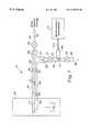
- FIG. 1is a schematic block diagram of the in-line diluting extractor of the present invention for the in-line extraction, dilution and conveyance of a representative sample of a processed medium for examination by a particle size distribution measurement instrument.
- FIG. 1there is shown the in-line diluting extractor of the present invention that is used to extract, dilute and convey a representative sample of a processed medium to particle measurement instrument.
- the diluting extractor shown generally at 10is comprised of a diluent delivery conduit 20 housed within a sample extraction conduit 30 , arranged in a coaxial relationship.
- the diluent delivery conduit 20is connected to a diluent supply conduit 25 .
- Delivery of a dilution medium to diluent delivery conduit 20is through a flow control device 26 .
- Flow control device 26can be a manually adjustable valve, petcock or other such device that can be manipulated to open, close or regulate the flow of diluent flowing through device 26 .
- a dilution medium stored in the diluent storage device(not shown) is conveyed to flow control device 26 via diluent supply conduit 25 .
- the diluting extractor 10has a probe end 15 configured in a pitot-like arrangement adapted to be presented into the processed medium to be analyzed.
- probe end 15includes an opening 35 extending from an outer surface of extraction conduit 30 to an inner chamber 36 .
- diluent delivery conduit 20includes an opening 27 that is in alignment with opening 35 . Opening 27 leads from an outer surface of diluent delivery conduit 20 into an inner chamber 36 .
- Probe end 15is arranged to be inserted into a pipe 40 in order to extract representative samples of a processed medium flowing in a process stream within a pipe or conduit 40 .
- Pipe 40can either be a main conduit that transports the processed medium during a process operation or a by-pass line that shunts a portion of the processed medium from the main conduit.
- the processed mediumflows within pipe 40 as a process stream in the direction shown by flow arrows F 3 .
- Probe end 15is presented into the process stream with the openings 27 and 35 facing flow F 3 .
- Extraction conduit 30further includes a sample delivery chamber 37 that connects the extraction conduit 30 , inner chamber 36 , to the fill end 52 of a sampling receptacle 50 .
- Sampling receptacle 50further includes a fill flow control device 51 located proximate fill end 52 .
- a drain end 56includes a drain flow control device 54 located proximate drain end 56 .
- Flow control devices 51 and 54define a sampling chamber or cell 55 therebetween.
- a probe 100is operatively connected via a signal path 115 to a particle measurement instrument 110 .
- the probe 100is arranged to be inserted into sampling chamber 55 .
- Measurement instrument 110is a device of the type commonly used in particle size distribution measurement and analysis and that employs angular light scattering or dynamic light scattering techniques to measure particle size distribution. In such instruments a conditioned sample representing the processed medium is deposited in sampling chamber or cell 100 , whereby the measurement instrument performs the measurement and analysis on the conditioned sample contained in the sampling chamber.
- a processed medium flowing in a process stream through pipe 40enters opening 35 and into chamber 36 .
- the impact force exerted by the process streamdrives a continuous stream of processed medium into chamber 36 which migrates through the extraction conduits inner chamber 36 in the direction shown by flow arrows F 2 .
- the processed medium extractedmigrates through chamber 36 and is delivered to chamber 37 .
- Opening flow control device 51allows the entry of processed medium from chamber 37 into sampling chamber 55 .
- the processed mediumflows into chamber 55 in the direction shown by flow arrow F 4 , thereby filling chamber 55 .
- flow control device 51When sampling chamber 55 is filled, flow control device 51 is closed, providing a sample for reading by the measurement instrument probe 100 . Upon completion of the measurement, flow control device 54 is opened and the sample is evacuated via drain end 56 in the direction shown by flow arrow F 5 . The sample flowing from drain end 56 can be either discarded or returned to the process stream of pipe 40 , downstream of probe end 15 . Flow control device 54 is then closed, preparing sampling chamber 55 for the next sample to be measured.
- the arrangement just describedillustrates a means of conveying on a demand basis a concentrated sample of the processed medium to the measurement instrument 110 for analysis.
- the representative samplein order for the measurement instrument to correctly measure particle size distribution, the representative sample must be conditioned. Conditioning introduces some form of diluent or clear suspending medium fluid to disperse the concentration. The dilution is accomplished by the introduction of a diluent medium to the processed medium before it is driven to the sampling chamber 55 .
- Opening flow control device 26allows the introduction of a clear diluent medium from a storage device (not shown) to diluent delivery conduit 20 .
- the diluentflows through flow control device 26 in the direction of flow arrow F 1 into the inner chamber 28 of diluent delivery conduit 20 .
- Any convenient method for extracting the diluent from the storage devicecan be employed, including, but not limited to, motor driven pumps or gravity feed.
- the diluentexits inner chamber 28 at opening 27 and is combined with the processed medium flowing through opening 35 , thereby forming a conditioned or diluted representative sample of the processed medium.
- the now conditioned representative samples being continually formedare driven by the impact force exerted by the process stream flowing in conduit 40 into delivery chamber 37 .
- opening flow control device 51allows the conditioned representative samples to enter and fill sampling chamber 55 , whereby they can be analyzed by measurement instrument 110 via probe 100 .
- flow control device 54is opened, draining chamber 55 in preparation of the next fill operation.
- the dilution ratiothat is, the amount of diluent that the representative sample extracted contains, is controlled by balancing the rate of flow of diluent with the flow of processed medium flowing into the extraction conduit 30 .
- the flow rate of processed medium into extraction conduit 30is a function of the impact force applied to opening 35 by the flow rate F 3 of the process stream.
- the total flow F 2 through chamber 36 and into delivery chamber 37is the sum of the flow rate of F 1 and F 3 . If the diluent flow rate F 1 is made large enough, the pressure of the diluent exiting opening 27 can exceed the pressure generated by the flow F 3 of the process stream against opening 35 . In this situation, diluent will flow into the process stream with no process sample being extracted.
- the concentration of the representative sample delivered to the sampling chamber 55can be controlled.
- a proper concentration of particles-to-diluentis required for an accurate measurement by measurement instrument 110 .
- flow control device 26can be manipulated manually to control the flow of diluent. This manual manipulation of the concentration, however, requires the constant attention of the measurement device output by an operator and the manual adjustment of flow control device 26 .
- diluentinto the diluent delivery conduit 20 can be effectively automated by connecting the signals representing the loading or attenuation of measurement instrument 100 to a controller device to automatically manipulate and control flow control device 26 in the manner taught by co-pending patent application Ser. No. 09/030,463, “A SYSTEM FOR THE IN-LINE EXTRACTION AND DILUTION OF A REPRESENTATIVE SAMPLE OF A PROCESSED MEDIUM”, filed on the same date herewith, now U.S. Pat. No. 6,020,960, and having a common assignee with the present invention and which is hereby incorporated by reference.
- the arrangement of the present inventionprovides an in-line diluting extractor that requires no mechanical pumping, seals, mixing chambers, gate valves or mechanical recirculating systems and, therefore, requires a minimal effort to operate and to maintain. Additionally, the present invention delivers to the measurement instrument a conditioned sample representative of the particles present in a processed medium on a real-time, in-situ basis without the time limitations imposed by the prior art systems. Finally, the conditioning and delivery system of the present invention provides an effective and simple system that can be used with any number of particle size distribution measurement instruments to effect the precise and cost-effective control of a processed medium.
Landscapes
- Life Sciences & Earth Sciences (AREA)
- Physics & Mathematics (AREA)
- Health & Medical Sciences (AREA)
- Chemical & Material Sciences (AREA)
- Analytical Chemistry (AREA)
- Biochemistry (AREA)
- General Health & Medical Sciences (AREA)
- General Physics & Mathematics (AREA)
- Immunology (AREA)
- Pathology (AREA)
- Hydrology & Water Resources (AREA)
- Sampling And Sample Adjustment (AREA)
Abstract
Description
The present application is related to co-pending application, Ser. No. 09/000,463, “A SYSTEM FOR THE IN-LINE EXTRACTION AND DILUTION OF A REPRESENTATIVE SAMPLE OF A PROCESSED MEDIUM”, filed on the same date herewith, now abandoned, and having a common assignee to the present invention.
This invention relates generally to the field of particle size distribution analysis and more particularly to a device for the in-line extraction and dilution of a representative sample of a processed medium for examination by a particle size distribution measurement instrument.
Particle size distribution is an important parameter in many processes and its accurate measurement is required for the precise and cost-effective control of the process. The measurement of particle size distribution in order to accurately control a process finds importance in industries that manufacture cement, cosmetics, pharmaceuticals and the like. A number of instruments are presently used in industry that use angular light scattering or dynamic light scattering techniques to measure particle size distribution in a liquid medium. These instruments analyze and measure the concentration of particles suspended in the liquid medium and provide a measurement that is used to adjust the process in order to correct for any irregularities in the final processed product. One such angular light scattering measurement instrument is taught in U.S. Pat. No. 5,416,580, to Trainer et al, issued May 16, 1995.
In order for these aforementioned instruments to measure correct particle size distribution, an extracted sample representative of the processed medium must be conditioned for measurement. Conditioning disperses the particles within the suspension into a concentration value that is within the concentration requirements of the measurement technique being utilized. The concentration of particles within a typical process is generally higher than is allowed by the measurement technique being utilized and the aforementioned conditioning introduces some form of dilution to disperse the concentration. For example, in the case of instruments that employ angular light scattering techniques, multiple scattering limits the concentration to less than 0.1% of particles in suspension. In the case of dynamic light scattering, particle-to-particle interactions limit concentration to less than 3%. Particle concentrations in a processed medium, however, can be as high as 50% by volume.
One method presently employed that overcomes these limitations is to deliver an extracted sample representative of the processed medium to a conditioning instrument, which works in association with the measurement instrument and dilutes, disperses and finally circulates the conditioned sample to the measurement instrument for analysis. After analysis, the diluted sample is discarded and the cycle repeated. Such conditioning instruments are taught in U.S. Pat. No. 4,496,244, to Ludwig et al, issued Jan. 29, 1985, and U.S. Pat. No. 5,439,288, to Hoffman et al, issued Aug. 8, 1995.
These arrangements have shortcomings in the need to transport a concentrated sample from the process location to the conditioning instrument, the time involved in the conditioning-circulating-flushing cycle and the final discarding of the dilute sample in preparation for the next sample extraction. Such conditioning instruments also suffer from poor reliability and excessive maintenance due inherently to the mechanical actions and motions of the multiple seals, valves, and conduits that are required to extract the sample from the processed medium, condition the extracted sample, and finally deliver the sample to the measurement instrument.
Therefore, there is provided by the present invention a device for the extraction and delivery of a diluted representative sample of a processed medium flowing in a process stream within a pipe or conduit to a particle measurement instrument for analysis. The device of the present invention includes an extraction conduit that includes a probe end which has an opening extending through an exterior surface of the conduit into an interior cavity. The probe end is arranged to be inserted into a pipe with the opening facing the flow of the process stream.
A diluent delivery conduit connected to a source of diluent medium is substantially housed within the extraction conduit cavity in coaxial alignment with the extraction conduit. A sample delivery passage is formed between the extraction conduit and the diluent delivery conduit. The sample delivery passage connects the device of the present invention to a sampling chamber or cell of a particle measurement instrument. The diluent delivery conduit further includes an opening in direct face-to-face alignment with the extraction conduit opening. Diluent medium flows out of the diluent delivery conduit opening in proximity to said extraction conduit opening.
Responsive to the impact force of the process stream, processed medium enters the extraction conduit opening and mixes with the diluent medium emitted by the diluent delivery conduit opening, thereby forming a stream of diluted processed medium samples. The diluted processed medium samples flow through the sample delivery passage to the sampling chamber of the particle measurement instrument, where they are analyzed.
Accordingly, it is an object of the present invention to provide a diluting and extraction device that delivers to a measurement instrument a conditioned sample representative of the particles present in a processed medium for the real-time, in-situ measurement analysis of the particle size distribution present in the processed medium without the time limitations imposed by the prior art systems.
It is another object of the present invention to provide a diluting and extraction device that requires no mechanical pumping, seals, mixers, gate valves, or mechanically-driven recirculating systems and, therefore, requires a minimal effort to operate and to maintain.
It is still another object of the present invention to provide an effective and simple diluting and extraction device that can be used with any number of particle size distribution measurement instruments to effect the precise and cost-effective control of a processed medium.
Other objects, features, and advantages of the present invention will be apparent from the following description of a preferred embodiment thereof, taken in conjunction with the single sheet of drawings, in which:
FIG. 1 is a schematic block diagram of the in-line diluting extractor of the present invention for the in-line extraction, dilution and conveyance of a representative sample of a processed medium for examination by a particle size distribution measurement instrument.
Turning to FIG. 1, there is shown the in-line diluting extractor of the present invention that is used to extract, dilute and convey a representative sample of a processed medium to particle measurement instrument. The diluting extractor shown generally at10, is comprised of adiluent delivery conduit 20 housed within asample extraction conduit 30, arranged in a coaxial relationship. Thediluent delivery conduit 20 is connected to adiluent supply conduit 25. Delivery of a dilution medium todiluent delivery conduit 20 is through aflow control device 26.Flow control device 26 can be a manually adjustable valve, petcock or other such device that can be manipulated to open, close or regulate the flow of diluent flowing throughdevice 26. A dilution medium stored in the diluent storage device (not shown) is conveyed toflow control device 26 viadiluent supply conduit 25.
The dilutingextractor 10 has aprobe end 15 configured in a pitot-like arrangement adapted to be presented into the processed medium to be analyzed. As can be seen in FIG. 1,probe end 15 includes an opening35 extending from an outer surface ofextraction conduit 30 to aninner chamber 36. Similarlydiluent delivery conduit 20 includes an opening27 that is in alignment with opening35.Opening 27 leads from an outer surface of diluent delivery conduit20 into aninner chamber 36.
Aprobe 100 is operatively connected via asignal path 115 to aparticle measurement instrument 110. Theprobe 100 is arranged to be inserted intosampling chamber 55.Measurement instrument 110 is a device of the type commonly used in particle size distribution measurement and analysis and that employs angular light scattering or dynamic light scattering techniques to measure particle size distribution. In such instruments a conditioned sample representing the processed medium is deposited in sampling chamber orcell 100, whereby the measurement instrument performs the measurement and analysis on the conditioned sample contained in the sampling chamber. A better understanding of such an instrument and the method used for measurement and analysis may be had by reference to U.S. Pat. No. 5,416,580, to Trainer et al, issued May 16, 1995.
With renewed reference to FIG. 1, an explanation of the operation of extracting a sample of the processed medium will now be given. A processed medium flowing in a process stream throughpipe 40, in the direction shown by flow arrows F3, enters opening35 and intochamber 36. The impact force exerted by the process stream drives a continuous stream of processed medium intochamber 36 which migrates through the extraction conduitsinner chamber 36 in the direction shown by flow arrows F2. The processed medium extracted migrates throughchamber 36 and is delivered tochamber 37. Openingflow control device 51 allows the entry of processed medium fromchamber 37 intosampling chamber 55. The processed medium flows intochamber 55 in the direction shown by flow arrow F4, thereby fillingchamber 55. When samplingchamber 55 is filled,flow control device 51 is closed, providing a sample for reading by themeasurement instrument probe 100. Upon completion of the measurement,flow control device 54 is opened and the sample is evacuated viadrain end 56 in the direction shown by flow arrow F5. The sample flowing fromdrain end 56 can be either discarded or returned to the process stream ofpipe 40, downstream ofprobe end 15.Flow control device 54 is then closed, preparingsampling chamber 55 for the next sample to be measured.
As it will be understood by those skilled in the art, the arrangement just described illustrates a means of conveying on a demand basis a concentrated sample of the processed medium to themeasurement instrument 110 for analysis. However, as was previously explained, in order for the measurement instrument to correctly measure particle size distribution, the representative sample must be conditioned. Conditioning introduces some form of diluent or clear suspending medium fluid to disperse the concentration. The dilution is accomplished by the introduction of a diluent medium to the processed medium before it is driven to thesampling chamber 55.
Returning to FIG. 1, the operation of the diluent delivery and the formulation of a conditioned representative sample of processed medium in accordance to the present invention will now be given. Openingflow control device 26 allows the introduction of a clear diluent medium from a storage device (not shown) todiluent delivery conduit 20. The diluent flows throughflow control device 26 in the direction of flow arrow F1 into theinner chamber 28 ofdiluent delivery conduit 20. Any convenient method for extracting the diluent from the storage device can be employed, including, but not limited to, motor driven pumps or gravity feed. The diluent exitsinner chamber 28 at opening27 and is combined with the processed medium flowing throughopening 35, thereby forming a conditioned or diluted representative sample of the processed medium. The now conditioned representative samples being continually formed are driven by the impact force exerted by the process stream flowing inconduit 40 intodelivery chamber 37. As was previously explained, openingflow control device 51 allows the conditioned representative samples to enter and fillsampling chamber 55, whereby they can be analyzed bymeasurement instrument 110 viaprobe 100. Upon completion of the measurement operation,flow control device 54 is opened, drainingchamber 55 in preparation of the next fill operation.
The dilution ratio, that is, the amount of diluent that the representative sample extracted contains, is controlled by balancing the rate of flow of diluent with the flow of processed medium flowing into theextraction conduit 30. The flow rate of processed medium intoextraction conduit 30 is a function of the impact force applied to opening35 by the flow rate F3 of the process stream. The total flow F2 throughchamber 36 and intodelivery chamber 37 is the sum of the flow rate of F1 and F3. If the diluent flow rate F1 is made large enough, the pressure of thediluent exiting opening 27 can exceed the pressure generated by the flow F3 of the process stream againstopening 35. In this situation, diluent will flow into the process stream with no process sample being extracted. At a lower diluent flow rate the pitot pressure at opening35 will exceed the pressure exerted by the flow of diluent F1 and processed medium will flow throughopening 35 and mix with the diluent. Therefore, by adjusting the flow F1 of diluent throughdevice 26, the concentration of the representative sample delivered to thesampling chamber 55 can be controlled. A proper concentration of particles-to-diluent is required for an accurate measurement bymeasurement instrument 110. By reading the measure of loading or attenuation from themeasurement instrument 110,flow control device 26 can be manipulated manually to control the flow of diluent. This manual manipulation of the concentration, however, requires the constant attention of the measurement device output by an operator and the manual adjustment offlow control device 26.
However, the introduction of diluent into thediluent delivery conduit 20 can be effectively automated by connecting the signals representing the loading or attenuation ofmeasurement instrument 100 to a controller device to automatically manipulate and controlflow control device 26 in the manner taught by co-pending patent application Ser. No. 09/030,463, “A SYSTEM FOR THE IN-LINE EXTRACTION AND DILUTION OF A REPRESENTATIVE SAMPLE OF A PROCESSED MEDIUM”, filed on the same date herewith, now U.S. Pat. No. 6,020,960, and having a common assignee with the present invention and which is hereby incorporated by reference.
The arrangement of the present invention provides an in-line diluting extractor that requires no mechanical pumping, seals, mixing chambers, gate valves or mechanical recirculating systems and, therefore, requires a minimal effort to operate and to maintain. Additionally, the present invention delivers to the measurement instrument a conditioned sample representative of the particles present in a processed medium on a real-time, in-situ basis without the time limitations imposed by the prior art systems. Finally, the conditioning and delivery system of the present invention provides an effective and simple system that can be used with any number of particle size distribution measurement instruments to effect the precise and cost-effective control of a processed medium.
The present invention has been described with particular reference to the preferred embodiments thereof. It will be obvious that various changes and modifications can be made therein without departing from the spirit and scope of the invention as defined in the appended claims.
Claims (3)
1. A device for the extraction and delivery of diluted representative samples of a processed medium, flowing in a process stream, for the analysis by a particle measurement instrument, said device comprising:
an extraction conduit including a probe end having an opening extending through an exterior surface of said extraction conduit into an interior cavity, said probe end located substantially within and transverse to said process stream with said opening facing the flow of said process stream;
a diluent delivery conduit having an interior bore connected to a source of diluent medium, said diluent delivery conduit substantially housed within said extraction conduit cavity in coaxial alignment with said extraction conduit, forming therebetween a sample delivery passage, said diluent delivery conduit including an opening extending through an exterior surface of said diluent delivery conduit into said bore in direct face-to-face alignment with said extraction conduit opening;
a flow control device connected to said diluent delivery conduit and to said source of diluent medium, said flow control device arranged to be operated to connect said source of diluent medium to said diluent delivery conduit bore and to control the flow rate of diluent medium released through said diluent delivery conduit opening; and
an extraction chamber connected to said sample delivery passage and to said particle measurement system, said flow control device operated to release diluent medium from said diluent delivery conduit opening over said extraction conduit opening at a flow rate less than the impact force exerted by said process stream against said extraction conduit opening whereby, responsive to said impact force, a portion of said processed medium enters said extraction conduit opening and mixes with said diluent medium in said sample delivery passage proximate said diluent delivery conduit opening, causing a stream of said diluted representative samples to flow through said sample delivery passage into said extraction chamber for analysis by said particle measurement instrument.
2. The device as claimed in claim1, wherein said process stream is contained within a conduit.
3. The device as claimed in claim1, wherein said device further includes a sample receptacle having a fill flow control device on a first end connecting said sample receptacle to said extraction chamber and a drain flow device on a second end forming a sampling chamber therebetween, said particle measurement instrument including a probe extending into said sampling chamber, whereby responsive to the operation of said fill flow control device said diluted representative samples enter said sampling chamber from said extraction chamber and said probe under control of said particle measurement instrument conducts an analysis of said diluted representative samples contained in said sampling chamber and upon termination of the analysis said drain flow control device is operated to empty the diluted representative samples from said sampling chamber.
Priority Applications (1)
| Application Number | Priority Date | Filing Date | Title |
|---|---|---|---|
| US09/030,239US6178830B1 (en) | 1998-02-25 | 1998-02-25 | In-line diluting extractor |
Applications Claiming Priority (1)
| Application Number | Priority Date | Filing Date | Title |
|---|---|---|---|
| US09/030,239US6178830B1 (en) | 1998-02-25 | 1998-02-25 | In-line diluting extractor |
Publications (1)
| Publication Number | Publication Date |
|---|---|
| US6178830B1true US6178830B1 (en) | 2001-01-30 |
Family
ID=21853245
Family Applications (1)
| Application Number | Title | Priority Date | Filing Date |
|---|---|---|---|
| US09/030,239Expired - Fee RelatedUS6178830B1 (en) | 1998-02-25 | 1998-02-25 | In-line diluting extractor |
Country Status (1)
| Country | Link |
|---|---|
| US (1) | US6178830B1 (en) |
Cited By (12)
| Publication number | Priority date | Publication date | Assignee | Title |
|---|---|---|---|---|
| DE10111833C1 (en)* | 2001-03-13 | 2002-07-04 | Parsum Ges Fuer Partikel Stroe | Measuring probe for determining size of moving particles in transparent medium, has auxiliary device for weakening particle flow fed to optical measuring point |
| WO2002092220A1 (en) | 2001-05-11 | 2002-11-21 | Avantium International B.V. | Reactor assembly |
| US20040050184A1 (en)* | 2001-01-31 | 2004-03-18 | Lennart Bjork | Sampling apparatus |
| US20100186523A1 (en)* | 2006-01-13 | 2010-07-29 | Hannu Vesala | Diluting sampler and a method for collecting and diluting a gaseous sample |
| US20110048105A1 (en)* | 2009-08-25 | 2011-03-03 | Caterpillar Inc. | Dilution System Test Apparatus With Added Capability And Method Of Operating Same |
| US20120017666A1 (en)* | 2010-07-23 | 2012-01-26 | Horiba, Ltd. | Exhaust gas analyzing system |
| WO2012072510A1 (en)* | 2010-12-02 | 2012-06-07 | Mettler-Toledo Ag | Sample capture element for sampling device |
| US8312780B2 (en) | 2010-06-25 | 2012-11-20 | Mettler-Toledo Ag | Sampling device and method |
| US8365617B2 (en) | 2010-06-25 | 2013-02-05 | Mettler-Toledo Ag | Sampling device |
| CN105466826A (en)* | 2015-12-31 | 2016-04-06 | 聚光科技(杭州)股份有限公司 | System and method for online monitoring particles |
| WO2021146645A2 (en) | 2019-01-15 | 2021-07-22 | Wyatt Technology Corporation | Flow cell, read head, and skid attachment |
| US20220276133A1 (en)* | 2016-04-28 | 2022-09-01 | Shanghai Kohler Electronics, Ltd. | Device for collecting liquid and smart toilet comprising the same |
Citations (6)
| Publication number | Priority date | Publication date | Assignee | Title |
|---|---|---|---|---|
| US3803921A (en)* | 1968-07-15 | 1974-04-16 | P Dieterich | Sampling and flow measuring device |
| US4385910A (en)* | 1981-12-23 | 1983-05-31 | Caterpillar Tractor Co. | Apparatus and method for producing a gas having a controlled water vapor content |
| US4700560A (en)* | 1985-05-22 | 1987-10-20 | American Hospital Supply Corporation | Calibration cell for calibration of gaseous or non-gaseous fluid constituent sensors |
| US5033318A (en)* | 1989-04-01 | 1991-07-23 | Fag Kugelfischer Georg Shafer, Kommanditgesellschaft | Apparatus for measuring the particulate contamination in flues containing corrosive dusts |
| US5596154A (en)* | 1995-09-21 | 1997-01-21 | Enviroplan, Inc. | Dilution control method and apparatus |
| US5753830A (en)* | 1994-02-28 | 1998-05-19 | Sunds Defibrator Industries Ab | Method and system for sampling in a material mixture |
- 1998
- 1998-02-25USUS09/030,239patent/US6178830B1/ennot_activeExpired - Fee Related
Patent Citations (6)
| Publication number | Priority date | Publication date | Assignee | Title |
|---|---|---|---|---|
| US3803921A (en)* | 1968-07-15 | 1974-04-16 | P Dieterich | Sampling and flow measuring device |
| US4385910A (en)* | 1981-12-23 | 1983-05-31 | Caterpillar Tractor Co. | Apparatus and method for producing a gas having a controlled water vapor content |
| US4700560A (en)* | 1985-05-22 | 1987-10-20 | American Hospital Supply Corporation | Calibration cell for calibration of gaseous or non-gaseous fluid constituent sensors |
| US5033318A (en)* | 1989-04-01 | 1991-07-23 | Fag Kugelfischer Georg Shafer, Kommanditgesellschaft | Apparatus for measuring the particulate contamination in flues containing corrosive dusts |
| US5753830A (en)* | 1994-02-28 | 1998-05-19 | Sunds Defibrator Industries Ab | Method and system for sampling in a material mixture |
| US5596154A (en)* | 1995-09-21 | 1997-01-21 | Enviroplan, Inc. | Dilution control method and apparatus |
Cited By (25)
| Publication number | Priority date | Publication date | Assignee | Title |
|---|---|---|---|---|
| US20040050184A1 (en)* | 2001-01-31 | 2004-03-18 | Lennart Bjork | Sampling apparatus |
| US6918310B2 (en)* | 2001-01-31 | 2005-07-19 | Astrazeneca Ab | Sampling apparatus |
| US20050262928A1 (en)* | 2001-01-31 | 2005-12-01 | Lennart Bjork | Sampling apparatus |
| US7213474B2 (en)* | 2001-01-31 | 2007-05-08 | Astrazeneca Ab | Sampling apparatus |
| DE10111833C1 (en)* | 2001-03-13 | 2002-07-04 | Parsum Ges Fuer Partikel Stroe | Measuring probe for determining size of moving particles in transparent medium, has auxiliary device for weakening particle flow fed to optical measuring point |
| WO2002092220A1 (en) | 2001-05-11 | 2002-11-21 | Avantium International B.V. | Reactor assembly |
| EP2263790A2 (en) | 2001-05-11 | 2010-12-22 | Avantium International B.V. | Reactor assembly |
| US8302495B2 (en)* | 2006-01-13 | 2012-11-06 | Teknologian Tutkimuskeskus Vtt | Diluting sampler and a method for collecting and diluting a gaseous sample |
| US20100186523A1 (en)* | 2006-01-13 | 2010-07-29 | Hannu Vesala | Diluting sampler and a method for collecting and diluting a gaseous sample |
| US20110048105A1 (en)* | 2009-08-25 | 2011-03-03 | Caterpillar Inc. | Dilution System Test Apparatus With Added Capability And Method Of Operating Same |
| US8505395B2 (en)* | 2009-08-25 | 2013-08-13 | Caterpillar Inc. | Dilution system test apparatus with added capability and method of operating same |
| US8312780B2 (en) | 2010-06-25 | 2012-11-20 | Mettler-Toledo Ag | Sampling device and method |
| US8365617B2 (en) | 2010-06-25 | 2013-02-05 | Mettler-Toledo Ag | Sampling device |
| US8789431B2 (en) | 2010-06-25 | 2014-07-29 | Mettler-Toledo Ag | Sampling device and method of use thereof |
| US20120017666A1 (en)* | 2010-07-23 | 2012-01-26 | Horiba, Ltd. | Exhaust gas analyzing system |
| US8528424B2 (en)* | 2010-07-23 | 2013-09-10 | Horiba, Ltd. | Exhaust gas analyzing system |
| WO2012072510A1 (en)* | 2010-12-02 | 2012-06-07 | Mettler-Toledo Ag | Sample capture element for sampling device |
| CN103238052A (en)* | 2010-12-02 | 2013-08-07 | 梅特勒-托利多公开股份有限公司 | Sample capture element for sampling device |
| CN105466826A (en)* | 2015-12-31 | 2016-04-06 | 聚光科技(杭州)股份有限公司 | System and method for online monitoring particles |
| US20220276133A1 (en)* | 2016-04-28 | 2022-09-01 | Shanghai Kohler Electronics, Ltd. | Device for collecting liquid and smart toilet comprising the same |
| US11686654B2 (en)* | 2016-04-28 | 2023-06-27 | Shanghai Kohler Electronics, Ltd. | Device for collecting liquid and smart toilet comprising the same |
| US11971335B2 (en) | 2016-04-28 | 2024-04-30 | Shanghai Kohler Electronics, Ltd. | Device for collecting liquid and smart toilet comprising the same |
| WO2021146645A2 (en) | 2019-01-15 | 2021-07-22 | Wyatt Technology Corporation | Flow cell, read head, and skid attachment |
| EP4090943A4 (en)* | 2019-01-15 | 2024-05-29 | Wyatt Technology, LLC | FLOW CELL, READING HEAD AND SLIDING PIECE MOUNTING |
| US12078594B2 (en) | 2019-01-15 | 2024-09-03 | Wyatt Technology, Llc | Read head |
Similar Documents
| Publication | Publication Date | Title |
|---|---|---|
| US6007235A (en) | Sampling and diluting system for particle size distribution measurement | |
| US6178830B1 (en) | In-line diluting extractor | |
| US5380491A (en) | Apparatus for pumping and directing fluids for hematology testing | |
| EP0278520B1 (en) | Automatic dilution system | |
| EP1592957B1 (en) | Multi-stage dilution system and method | |
| US6979569B1 (en) | Apparatus and method for mixing fluids for analysis | |
| US5728351A (en) | Apparatus for making a plurality of reagent mixtures and analyzing particle distributions of the reagent mixtures | |
| US3946113A (en) | Continuous separating and standardizing of milk | |
| US6947126B2 (en) | Dilution apparatus and method of diluting a liquid sample | |
| US6812032B1 (en) | Apparatus and method for making a plurality of reagent mixtures and analyzing particle distributions of the reagent mixtures | |
| US3829584A (en) | Continuous separating and standardizing of milk | |
| CN107970860A (en) | A kind of system of continuous automatic dilution hydrazine hydrate | |
| US3109713A (en) | Liquid analysis apparatus with closed flow cell | |
| US5983709A (en) | Device and method for measuring, monitoring, and controlling fat and protein concentration in standardized milk | |
| US7871194B2 (en) | Dilution apparatus and method | |
| US6020960A (en) | System for the in-line extraction and dilution of a representative sample of a processed medium | |
| CN209069778U (en) | Microfluidizer nano particle size on-line measuring device | |
| US20030076495A1 (en) | Apparatus and method for sampling a chemical-mechanical polishing slurry | |
| US3747412A (en) | Sample mixing and metering apparatus | |
| DE2827537A1 (en) | OPERATING METHOD FOR A LEAK DETECTING DEVICE, GAS ANALYSIS OR THE LIKE. AND SUITABLE FURNITURE | |
| RU2569556C1 (en) | Method for radioactive solution sample delivery and device for implementing it (versions) | |
| JPS63132170A (en) | Method for co-cleaning of pipeline of analysis instrument of the like | |
| JPH04138354A (en) | Process liquid chromatograph | |
| US4827775A (en) | Apparatus for extracting a sample | |
| JPH0635948U (en) | Laser diffraction particle size analyzer |
Legal Events
| Date | Code | Title | Description |
|---|---|---|---|
| AS | Assignment | Owner name:HONEYWELL INC., MINNESOTA Free format text:ASSIGNMENT OF ASSIGNORS INTEREST;ASSIGNOR:FREUD, PAUL J.;REEL/FRAME:009400/0675 Effective date:19980311 Owner name:HONEYWELL INC., MINNESOTA Free format text:ASSIGNMENT OF ASSIGNORS INTEREST;ASSIGNOR:FREUD, PAUL J.;REEL/FRAME:009322/0874 Effective date:19980311 | |
| AS | Assignment | Owner name:MICROTRAC, INC., PENNSYLVANIA Free format text:SALE OF ASSETS;ASSIGNOR:HONEYWELL, INC.;REEL/FRAME:010742/0451 Effective date:19991231 | |
| CC | Certificate of correction | ||
| REMI | Maintenance fee reminder mailed | ||
| LAPS | Lapse for failure to pay maintenance fees | ||
| STCH | Information on status: patent discontinuation | Free format text:PATENT EXPIRED DUE TO NONPAYMENT OF MAINTENANCE FEES UNDER 37 CFR 1.362 | |
| FP | Lapsed due to failure to pay maintenance fee | Effective date:20050130 |