US6177962B1 - Apparatus and method for preventing oversaturation of chrominance signals - Google Patents
Apparatus and method for preventing oversaturation of chrominance signalsDownload PDFInfo
- Publication number
- US6177962B1 US6177962B1US09/343,622US34362299AUS6177962B1US 6177962 B1US6177962 B1US 6177962B1US 34362299 AUS34362299 AUS 34362299AUS 6177962 B1US6177962 B1US 6177962B1
- Authority
- US
- United States
- Prior art keywords
- signal
- chroma
- vector
- saturation
- vector component
- Prior art date
- Legal status (The legal status is an assumption and is not a legal conclusion. Google has not performed a legal analysis and makes no representation as to the accuracy of the status listed.)
- Expired - Lifetime
Links
- 238000000034methodMethods0.000titleclaimsdescription8
- 239000013598vectorSubstances0.000claimsabstractdescription92
- 230000000670limiting effectEffects0.000claimsabstractdescription19
- 238000012545processingMethods0.000claimsdescription18
- 238000000926separation methodMethods0.000claimsdescription2
- 230000000087stabilizing effectEffects0.000claims2
- 230000001934delayEffects0.000claims1
- 230000001747exhibiting effectEffects0.000abstract1
- 238000009738saturatingMethods0.000abstract1
- 238000010586diagramMethods0.000description8
- 230000009467reductionEffects0.000description5
- 229920006395saturated elastomerPolymers0.000description5
- 230000004044responseEffects0.000description4
- 230000000694effectsEffects0.000description3
- 230000002829reductive effectEffects0.000description3
- 238000012546transferMethods0.000description3
- 239000000470constituentSubstances0.000description2
- 230000001276controlling effectEffects0.000description2
- 238000012986modificationMethods0.000description2
- 230000004048modificationEffects0.000description2
- 238000013459approachMethods0.000description1
- 239000003990capacitorSubstances0.000description1
- 230000008859changeEffects0.000description1
- 230000000295complement effectEffects0.000description1
- 230000002596correlated effectEffects0.000description1
- 230000007423decreaseEffects0.000description1
- 230000003247decreasing effectEffects0.000description1
- 230000006735deficitEffects0.000description1
- 230000000593degrading effectEffects0.000description1
- 238000013461designMethods0.000description1
- 238000009499grossingMethods0.000description1
- 230000002401inhibitory effectEffects0.000description1
- 238000005259measurementMethods0.000description1
- 230000008569processEffects0.000description1
- 230000001012protectorEffects0.000description1
- 230000001105regulatory effectEffects0.000description1
- 238000005070samplingMethods0.000description1
Images


Classifications
- H—ELECTRICITY
- H04—ELECTRIC COMMUNICATION TECHNIQUE
- H04N—PICTORIAL COMMUNICATION, e.g. TELEVISION
- H04N9/00—Details of colour television systems
- H04N9/64—Circuits for processing colour signals
- H04N9/67—Circuits for processing colour signals for matrixing
- H—ELECTRICITY
- H04—ELECTRIC COMMUNICATION TECHNIQUE
- H04N—PICTORIAL COMMUNICATION, e.g. TELEVISION
- H04N9/00—Details of colour television systems
- H04N9/64—Circuits for processing colour signals
- H04N9/68—Circuits for processing colour signals for controlling the amplitude of colour signals, e.g. automatic chroma control circuits
Definitions
- This inventionrelates to a video signal processing apparatus, and in particular, to a chroma overload protection apparatus.
- Chroma overload circuitsare commonly used to prevent oversaturated chroma which may result from “channel impairments” in a video system such as tuner tilt, multipath propagation effects, noise or the like.
- a conventional form of chroma overload protection circuitoperates by adjusting the gain of the chroma signal in response to an average chroma level during active video time intervals after automatic chroma control (ACC) processing.
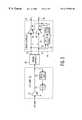
- FIG. 1illustrates an example of such a system.
- the conventional system of FIG. 1comprises series connected ACC unit 10 and chroma overload unit 20 (each outlined in phantom) followed by chroma signal separator circuit 30 which separates the chroma signal into its component vector components, U and V for further processing (e.g., demodulation to baseband and matrixing to provide baseband color difference output signals R-Y and B-Y).
- ACC unit 10comprises controllable gain amplifier 12 to which a chroma input signal is applied and a feedback path from the output of amplifier 12 to control input 14 thereof.
- the feedback pathcomprises a series connection of burst gate 16 and automatic chroma control circuit (ACC) 18 .
- Chroma overload circuit 20is also feedback controlled and comprises controllable gain amplifier 22 which is coupled at the input thereof to receive the ACC controlled chroma from unit 10 and is provided with feedback to control input 24 thereof via a series connection of gate 26 and average detector 28 .
- Chroma signal separation into its component vectorsis performed after chroma ACC and chroma overload protection by chroma signal separator circuit 30 connected to the output of overload circuit 20 to provide separated chroma vector component output signals U and V.
- burst gate 16passes the color burst component of the chroma signal to ACC unit 18 which compares the burst amplitude with a reference level and provides a control signal to control input 14 of amplifier 12 to adjust the chroma signal amplitude to a predetermined level. In this way, the amplitude of the overall chroma signal C is stabilized at a predictable value based on the burst amplitude relative to the reference or desired level. If the burst amplitude increases, the gain of amplifier 12 decreases to thereby stabilize the average chroma signal level. Some smoothing may be included in ACC unit 18 to prevent noise which may be present on the gated burst signal from disturbing the regulated chroma output signal level.
- chroma overload circuit 20In the operation of chroma overload circuit 20 , gate 26 is open during the active video trace interval and closed otherwise to thereby pass only chroma to average detector 28 .
- ACC detector 18serves to regulate the chroma level based on the gated burst amplitude.
- Overload detector 28serves to provide chroma overload limiting based on the average chroma level (rather than the burst level). For this purpose, the time constant of average detector 28 as well as the gain characteristic of gain controlled amplifier 22 determine the behavior of the overload circuit.
- the attack and decay time constants of detector 28may be different, and detector 28 may be implemented as a so-called “leaky peak detector” (e.g., a capacitor with a fast charging circuit and a parallel connected “leak” resistor to provide a relatively slow discharge time constant).
- detector 28may be implemented as a so-called “leaky peak detector” (e.g., a capacitor with a fast charging circuit and a parallel connected “leak” resistor to provide a relatively slow discharge time constant).
- the response time constantis usually on the order of a video field (e.g., 17 milli-Seconds).
- This long time constantmay have a tendency to reduce visible artifacts associated with modulating the chroma gain.
- italso may allow instantaneous levels of the chroma signal to exceed desired levels resulting in undesirable oversaturation of the chroma of displayed images.
- a further aspect of the problem, as herein recognized,is that in an analog system, “head room” is provided to accommodate this instantaneous chroma signal condition which may cause oversaturation.
- head roomis provided to accommodate this instantaneous chroma signal condition which may cause oversaturation.
- a digital systemfor example, one supporting a CCIR 601/656 interface standard, there may be little “head room” provided for chroma in the system standard.
- chroma levels exceeding the 8-bit (or sometime 10-bit) range for the chroma componentsmay be “hard limited” (e.g., by truncation). Since U and V may be limited separately after demodulation, chroma overload may produce an objectionable tint shift in displayed images.
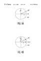
- FIGS. 2A and 2BThe problem of chroma overload is further illustrated in the phasor (vector) diagrams of FIGS. 2A and 2B.
- an over-saturated chroma vector Cwhich exceeds a desired saturation limit represented by grid 200 , and its constituent component vectors, U and V.
- FIG. 2Bshows the effect of limiting the constituent vectors.
- vector Uis limited to a magnitude of U-LIM (“LIM” is the limiting value)
- vector Vis not limited.
- the resultant vector C-LIMhas a different angle, and therefore a different tint, than vector C. This can result in a particularly objectionable type of picture artifact to the eye.
- the solution to the problem of chroma tint shifts upon overload of one or more vector componentsis provided by controlling chroma saturation on a pixel-by-pixel basis.
- this approachprevents tint shifts on over-saturated pixels.
- this solutionalso eliminates (not just reduces) visible artifacts associated with larger time-constant methods of modulating the chroma gain.
- Chroma overload protection apparatusin accordance with the invention comprises a source for providing a chrominance signal having first and second vector components; a separator, coupled to said source, for separating said chrominance signal into the first vector component and the second vector component; and an overload compensator, coupled to the separator, for adjusting the magnitude of the first and second vector components as a given function of a detected saturation level of the chrominance signal on a pixel by pixel basis.
- the compensatorcomprises a saturation calculator responsive to the first and second vector components for providing a saturation indicating signal converter responsive to the saturation indicating signal for providing a gain control signal; and gain control means, responsive to the gain control signal, for concurrently adjusting the gain of the first vector component in a first signal path and of the second vector component in a second signal path.
- a method, in accordance with the invention, for providing chroma overload protectioncomprises the steps of: providing a chrominance signal having first and second vector components; separating the chrominance signal into the first vector component and the second vector component; and adjusting the magnitude of the first and second vector components as a given function of a detected saturation level of the chrominance signal on a pixel by pixel basis.
- FIG. 1is a block diagram of a conventional chroma overload system
- FIGS. 2A and 2Bare vector diagrams illustrating the effect on tint of the system of FIG. 1 under chroma overload conditions
- FIG. 3is a simplified block diagram of chroma overload protection apparatus embodying the invention.
- FIG. 4is a vector diagram illustrating operation of the apparatus of FIG. 3 under chroma over-load conditions
- FIG. 5is a detailed circuit diagram of the apparatus of FIG. 3 and embodying further aspects of the invention.
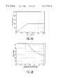
- FIGS. 6A, 6 B, 7 A and 7 Bare diagrams illustrating exemplary signal transfer characteristics of certain elements of the apparatus of FIG. 5 .
- Controlling saturation on a pixel-by-pixel basisincludes measurement of saturation on a pixel-by-pixel basis. This calculation is best performed, in accordance with the invention, by processing separated or “demodulated” chroma vector components. Accordingly, in the embodiment of the invention of FIG. 3, the chrominance signal after ACC processing in ACC unit 10 is separated into component vectors U and V by chroma separator 30 prior to processing in chroma overload protection circuit 50 .
- Chroma overload protection circuit 50(outlined in phantom) in FIG. 3 comprises a pair of inputs 52 and 54 coupled to receive the separated vector components U and V of the chrominance signal C provided by the chrominance signal separator 30 .
- Separator 30may be of conventional design.
- separator 30may be implemented by providing the chrominance signal samples at four times the color subcarrier frequency and separating out the odd samples to provide the vector component U and taking the even samples to provide the vector component V.
- Inputs 52 and 54are coupled to respective outputs 56 and 58 by means of respective controllable gain amplifiers 60 and 62 each having respective gain control inputs 64 and 66 connected in common and to output 70 of gain characteristic control circuit 72 .
- Input 74 of gain characteristic control circuit 72is coupled to output 76 of saturation calculator 78 having respective inputs 80 and 82 coupled to respective outputs 54 and 52 of chroma separator 30 for receiving respective ones of the separated chrominance signal component vectors U and V.
- saturation calculator 78determines the vector magnitude of the outputs of chroma signal separator 30 . Since the component vectors U and V are quadrature related, the chrominance vector C may be reconstructed from its two vector components by forming the square root of the sum of the squares of the component vectors U and V or a suitable approximation thereof (as discussed later). The resultant vector is used to control the gain of the U and V channels (i.e., the gains of amplifiers 60 and 62 . Since the gains of both channels are identical, saturation is reduced without affecting tint. The manner in which the magnitude affects the gain is determined by the transfer characteristic of gain characteristic control circuit 72 . This transfer characteristic may be tailored to provide either a hard clipping or a soft clipping (or “limiting”) characteristic as shown and described later.
- FIGS. 4A and 4Bfurther illustrate how the pixel-by-pixel chroma overload circuit reduces the oversaturated vector C without changing the tint.
- the gains of the U and V channelsare identically adjusted to produce modified U′ and V′ vector components.
- the dashed circle 400 in FIG. 4Arepresents the locus of a desired saturation level.
- the chroma vector Cis greater than the desired saturation level resulting in its vector component U exceeding the desired saturation level also.
- Component Vis shown to be within the desired range.
- FIG. 4Billustrates how the reduction of the amplitudes of the U and V vectors in equal proportions (using the gain characteristic of unit 72 ) to form reduced vectors U′ and V′ results in a reduction in the vector sum thereof (C′) to the desired limiting value represented by dashed circle 400 .
- FIG. 5illustrates a detailed digital embodiment of the chroma overload apparatus of FIG. 3 .
- a sampling clock frequency of four times the color subcarrieris assumed.
- the arithmetic usedis in twos complement.
- the arithmetic conventionis straight (un-signed) binary.
- the bit width of all signal lines or buses greater than one bitis signified by a diagonal hash mark ( ⁇ ) drawn through the line with a number written above the hash mark signifying the number of bits. If a hash mark is not present, then the signal line is one bit wide.
- Signal delay valuesare illustrated in two ways.
- the delayequals a number of clock cycles equal to the magnitude of the Z-transform exponent.
- the numberindicates the processing delay in clock cycles. If no delay is indicated for a circuit element, then the element processing time is negligible compared to a clock cycle.
- input terminals 52 and 54 and output terminals 56 and 58use the same designators as in the example of FIG. 3 .
- Terminals 52 and 54are coupled, as in the previous example, to receive the chroma vector components Uin and Vin from separator 30 and outputs 56 and 58 represent the output of the overload circuit providing the processed output signals Uout and Vout.
- Controllable gain amplifiers 60 and 62 of the previous exampleare implemented in this example of the invention by two digital signal processing channels or paths 510 and 520 which control the amplitude of the U and V chroma components.
- Path 510comprises multiplier 512 having an input coupled by two-clock delay unit 511 to input 52 for receiving chroma vector U and having an output coupled via limiter 513 and symmetrical rounding unit 514 to output 56 .
- Path 520is identical to path 510 and comprises delay unit 521 , multiplier 522 , limiter 523 and symmetrical rounding unit 524 coupled in series from input 54 to output 58 .
- symmetrical rounding unitsin the U and V signal paths advantageously ensures that the bit reduction of 18 to 12 bits for the output signals does not introduce any significant “rounding error” in the chroma vectors Uout and Vout.
- a “rounding error”may produce a DC shift in the output signals and so may produce an undesired tint shift.
- Symmetrical roundingprevents any significant error and any significant tint shift due to rounding. Examples of rounding circuits, suitable for use in the present invention for the purpose of ensuring tint integrity during limiting, are described, for example, by Hague et al. in U.S. Pat. No. 5,696,710 which issued Dec. 9, 1997.
- gain control circuit 530(outlined in phantom) which includes magnitude approximation unit 78 A and look-up table unit 72 A which provide similar functions to units 78 and 72 of the previous example and which provide additional features of the invention as well.
- the magnitude approximation (or arithmetic processing) unit 78 Ahas inputs 80 and 82 coupled to receive component vector signals V and U provided by separator 30 as previously explained and has output 76 coupled via limiter 79 to a control or address input of look-up table unit 72 A the output of which is coupled via inhibit gate 503 to gain control output terminal 502 .
- Output 502applies a gain control signal G developed in look up table 72 A in common to multipliers 512 and 522 in the U and V signal processing paths 510 and 520 . Since the same signal is applied to both multipliers, the amplitudes of the two chroma vectors U and V are controlled in direct proportion to any change in the gain control signal, G.
- gain control circuit 530comprises plurality of additional input terminals 541 - 544 and OR gate 550 which facilitate further features of the invention including selection of limiting characteristics and output signal inhibiting.
- Input 541is provided for receiving a table selection signal, TS, from a suitable source and for applying the table selection signal to table selection input 505 of look up table unit 72 A.
- Exemplary tablesinclude a table for hard “clipping” or limiting and a table providing “soft” clipping or limiting of the gain control signal supplied to the multipliers. Examples of these tables are discussed later with regard to FIGS. 6B and 7B.
- Input terminals 542 , 543 and 544are provided for receiving inhibit input signals for reducing the gain of chroma component vector processing channels 510 to zero under certain circumstances.
- these input signalsmay comprise, illustratively, a “color off” control signal, a “sync gate” indicator signal and a “color killer” input signal and are applied to the inhibit input of gate 503 via OR gate 550 so that if any signal is present, gate 503 will be inhibited and multipliers 512 and 522 in chroma vector component paths 510 and 520 will therefore reduce the path gain to zero thus preventing the vectors U and V from reaching outputs 56 and 58 .
- the saturation valuecould be calculated exactly using the function that the vector C is equal to the square root of the sum of the squares of the component vectors U and V or a suitable approximation thereof.
- the magnitudeis approximated using the formula indicated wherein “a” and “b” correspond to the U and V vector components of the chroma signal C.
- this formula Cis found by summing the magnitudes of “a” and “b” with the maximum (MAX) value of the absolute values of “a” and “b”, multiplying the sum by 3 and dividing the result by 256. For the 12 bit input signals shown, and the scaling factors selected, this results in a 7 bit output signal that is reduced to 6 bits by limiter 79 .
- the approximation usedhas been found to be accurate to within about twelve percent and is very easy to implement as compared to the exact calculation of the square root of the sum of the squares.
- the gain factor of 3/128is used to map the magnitude approximation into a useful range for gain characteristic block 72 A as discussed later.
- limiter 79is not strictly necessary because it is quite unlikely that the output of unit 78 A will ever reach a full 7 bits. This is because the chroma components are to a certain degree correlated and it is not likely that both will reach maximums at the same time for any given pixel. One might, therefore, eliminate limiter 79 . It may be included, however, as a matter of good engineering practice to ensure that under no circumstances, including even unlikely ones, that chroma will experience overload in the system.
- look up tablesare used to implement gain characteristic block 72 A.
- Two tablesare provided, a “hard-clip” or “hard limit” table and a “soft clip” or “soft limit” table.
- the choice of tableis selected by table selection signal TS applied to input 541 .
- This controlcould be provided by a user of apparatus employing the described chroma overload protector but, as a practical matter, the choice of look up tables is more likely to be provided by a manufacturer based upon the needs of particular television apparatus being designed. For example, one table might be more appropriate for chroma processing prior to signal source selection in a television apparatus and a different table might be a more appropriate choice with regard to chroma signal processing which may be done after input signal selection.
- FIGS. 6A, 6 B, 7 A and &Bprovide further details with regard to table look up unit 72 A. It is helpful to an understanding of this aspect of the invention that the look up tables are “saturation-in/gain-out” tables. In order to generate the look up table entries, the desired “saturation-in/saturation-out” characteristics are first determined. These characteristics may then be converted to the required look up table entries by using the relationship:
- the ordinate and abscissaare expressed in bits of the chrominance signal vector. From zero up to 1023 bits the desired response is linear (no limiting or clipping desired) and after that it is limited to an output of 1023 bits. For the system gain and scale factors used, this point of limiting occurs at a saturation level of 100% (see the locus of points 400 in FIG. 4B) and this is the maximum value for the overall vector sum of the component vectors Uout and Vout. Accordingly, after allowance for a bit reduction to 7 bits, the “gain out/saturation in” table of FIG.
- FIGS. 7A and 7Bare similar for the “soft clipping” case except that in this case the saturation in vs saturation out table is piece-wise approximated up to the limiting value by two line segments, the first having a linear slope for linear response below limiting and the second having about half that slope to begin the limiting process earlier. This results, as shown in FIG. 7B, in a look up table which begins reducing gain earlier than in the previous example.
- the use of the soft-clipping characteristicallows the nominal chroma level into the chroma overload circuit to be increased. (Note that this can be adjusted via the automatic chroma control ACC setting). This has been found to improve the appearance of under-saturated video without degrading normal or over-saturated video.
Landscapes
- Engineering & Computer Science (AREA)
- Multimedia (AREA)
- Signal Processing (AREA)
- Processing Of Color Television Signals (AREA)
- Control Of Amplification And Gain Control (AREA)
Abstract
Description
Claims (13)
Priority Applications (7)
| Application Number | Priority Date | Filing Date | Title |
|---|---|---|---|
| US09/343,622US6177962B1 (en) | 1999-06-30 | 1999-06-30 | Apparatus and method for preventing oversaturation of chrominance signals |
| KR1020000032234AKR100749412B1 (en) | 1999-06-30 | 2000-06-12 | Chroma overload protection apparatus and a method for providing chroma overload protection |
| EP00112863AEP1065886B1 (en) | 1999-06-30 | 2000-06-19 | Chroma overload protection apparatus and method |
| DE60037074TDE60037074T2 (en) | 1999-06-30 | 2000-06-19 | Color overload protection device and method |
| JP2000183909AJP4600952B2 (en) | 1999-06-30 | 2000-06-20 | Chroma overload protection device |
| MYPI20002911AMY118662A (en) | 1999-06-30 | 2000-06-27 | Apparatus and method for preventing oversaturation of chrominance signals. |
| CNB001184636ACN1198470C (en) | 1999-06-30 | 2000-06-30 | Colourity overload protection device |
Applications Claiming Priority (1)
| Application Number | Priority Date | Filing Date | Title |
|---|---|---|---|
| US09/343,622US6177962B1 (en) | 1999-06-30 | 1999-06-30 | Apparatus and method for preventing oversaturation of chrominance signals |
Publications (1)
| Publication Number | Publication Date |
|---|---|
| US6177962B1true US6177962B1 (en) | 2001-01-23 |
Family
ID=23346864
Family Applications (1)
| Application Number | Title | Priority Date | Filing Date |
|---|---|---|---|
| US09/343,622Expired - LifetimeUS6177962B1 (en) | 1999-06-30 | 1999-06-30 | Apparatus and method for preventing oversaturation of chrominance signals |
Country Status (7)
| Country | Link |
|---|---|
| US (1) | US6177962B1 (en) |
| EP (1) | EP1065886B1 (en) |
| JP (1) | JP4600952B2 (en) |
| KR (1) | KR100749412B1 (en) |
| CN (1) | CN1198470C (en) |
| DE (1) | DE60037074T2 (en) |
| MY (1) | MY118662A (en) |
Cited By (12)
| Publication number | Priority date | Publication date | Assignee | Title |
|---|---|---|---|---|
| US6536042B1 (en)* | 1998-05-21 | 2003-03-18 | Avaya Technology Corp. | Signal distribution system with integrated IR signal control |
| US20030063221A1 (en)* | 2001-04-11 | 2003-04-03 | Stessen Jeroen Hubert Christoffel Jacobus | Picture signal contrast control |
| US20030160894A1 (en)* | 2000-09-26 | 2003-08-28 | Tanio Nagasaki | Image processing apparatus and method, and recorded medium |
| US20040001234A1 (en)* | 2002-07-01 | 2004-01-01 | Xerox Corporation | Digital de-screening of documents |
| US20040041951A1 (en)* | 2002-08-23 | 2004-03-04 | Samsung Electronics Co., Ltd. | Method for color saturation adjustment with saturation limitation |
| US20040120576A1 (en)* | 2002-12-20 | 2004-06-24 | Samsung Electronics Co., Ltd. | Color signal correction device and method, and image processing system using the same and method thereof |
| US6873363B1 (en)* | 1999-02-16 | 2005-03-29 | Micron Technology Inc. | Technique for flagging oversaturated pixels |
| US6947099B2 (en)* | 2000-12-21 | 2005-09-20 | Thomson Licensing | Automatic chroma control circuit with controlled saturation reduction |
| US20080095430A1 (en)* | 2004-07-20 | 2008-04-24 | Koninklijke Philips Electronics, N.V. | Maintenance of Color Maximum Values in a Color Saturation Controlled Color Image |
| US20100026889A1 (en)* | 2006-12-29 | 2010-02-04 | Robert Bosch Gmbh | Apparatus, Process and Computer Program for Limiting the Vector Length of Colour Vectors |
| US20100245379A1 (en)* | 2009-03-26 | 2010-09-30 | Seiko Epson Corporation | Image display apparatus |
| US20150098023A1 (en)* | 2013-10-04 | 2015-04-09 | Amlogic Co., Ltd. | Chroma Automatic Gain Control |
Families Citing this family (6)
| Publication number | Priority date | Publication date | Assignee | Title |
|---|---|---|---|---|
| US7958769B2 (en) | 2005-02-14 | 2011-06-14 | Olympus Ndt | Detection of channel saturation in phase-array ultrasonic non-destructive testing |
| TWI466093B (en)* | 2007-06-26 | 2014-12-21 | Apple Inc | Management techniques for video playback |
| TWI489442B (en)* | 2008-04-03 | 2015-06-21 | Sunplus Technology Co Ltd | Adaptive color space conversion system and method |
| CN101309432B (en)* | 2008-04-21 | 2010-10-13 | 友达光电股份有限公司 | Saturation adjusting method and related color adjusting system |
| KR101310076B1 (en) | 2011-11-16 | 2013-09-24 | 한양대학교 에리카산학협력단 | Apparatus and method for restoration color image |
| KR102714197B1 (en)* | 2022-06-09 | 2024-10-04 | 연세대학교 산학협력단 | METHOD AND APPARATUS FOR COMPRESSIVE SENSING ENCODING of COLOR IMAGE |
Citations (13)
| Publication number | Priority date | Publication date | Assignee | Title |
|---|---|---|---|---|
| US4054905A (en) | 1976-10-28 | 1977-10-18 | Rca Corporation | Automatic chrominance gain control system |
| US4316213A (en) | 1980-09-23 | 1982-02-16 | Rca Corporation | Video processor employing variable amplitude compression of the chrominance component |
| US4359756A (en) | 1981-06-29 | 1982-11-16 | Rca Corporation | Chrominance signal limiter |
| US4447826A (en) | 1982-03-18 | 1984-05-08 | Rca Corporation | Digital television receiver automatic chroma control system |
| US4500910A (en) | 1982-11-30 | 1985-02-19 | Rca Corporation | Hue control system |
| US4573069A (en) | 1984-03-29 | 1986-02-25 | Rca Corporation | Chrominance fine gain control in a digital television receiver |
| US4602276A (en) | 1984-04-12 | 1986-07-22 | Rca Corporation | Digital signal level overload system |
| US4604645A (en) | 1983-09-30 | 1986-08-05 | Rca Corporation | Coarse/fine automatic chrominance gain control using a gain adjustable IF amplifier in a digital television receiver |
| US4630102A (en) | 1984-10-10 | 1986-12-16 | Rca Corporation | Digital chroma overload system |
| US4635102A (en) | 1984-10-24 | 1987-01-06 | Rca Corporation | Chroma signal amplitude control apparatus |
| US4962417A (en) | 1988-05-12 | 1990-10-09 | Rca Licensing Corporation | Chroma overload detector using a differential amplifier |
| US5619280A (en) | 1994-04-14 | 1997-04-08 | Matsushita Electric Industrial Co., Ltd. | Color conversion apparatus that restricts the color reproduction range of primary color signals |
| US5696710A (en) | 1995-12-29 | 1997-12-09 | Thomson Consumer Electronics, Inc. | Apparatus for symmetrically reducing N least significant bits of an M-bit digital signal |
Family Cites Families (12)
| Publication number | Priority date | Publication date | Assignee | Title |
|---|---|---|---|---|
| DE3884597D1 (en)* | 1988-01-21 | 1993-11-04 | Itt Ind Gmbh Deutsche | DIGITAL COLOR SIGNAL PROCESSING CIRCUIT. |
| JPH03119502A (en)* | 1989-10-02 | 1991-05-21 | Victor Co Of Japan Ltd | Audio signal dubbing system |
| JPH04891A (en)* | 1990-04-17 | 1992-01-06 | Sharp Corp | Digital tv receiver |
| JPH0537951A (en)* | 1991-07-29 | 1993-02-12 | Victor Co Of Japan Ltd | Digital acc circuit |
| JPH0678320A (en)* | 1992-08-25 | 1994-03-18 | Matsushita Electric Ind Co Ltd | Color adjustment device |
| JP3158768B2 (en)* | 1993-04-01 | 2001-04-23 | 松下電器産業株式会社 | Color signal amplitude limiter for video signals |
| JP2500603B2 (en)* | 1993-05-12 | 1996-05-29 | 日本電気株式会社 | Color signal base clip circuit |
| JPH0795611A (en)* | 1993-09-20 | 1995-04-07 | Toshiba Corp | Color saturation correction circuit |
| BE1007590A3 (en)* | 1993-10-01 | 1995-08-16 | Philips Electronics Nv | Video signal processing circuit. |
| JPH07212787A (en)* | 1994-01-24 | 1995-08-11 | Kyoei Sangyo Kk | Color signal processing circuit |
| JPH07274195A (en)* | 1995-05-11 | 1995-10-20 | Hitachi Denshi Ltd | Color adaptive gain control circuit |
| KR0154834B1 (en)* | 1995-06-20 | 1998-11-16 | 김광호 | Saturation control apparatus of color signal enabling gain control |
- 1999
- 1999-06-30USUS09/343,622patent/US6177962B1/ennot_activeExpired - Lifetime
- 2000
- 2000-06-12KRKR1020000032234Apatent/KR100749412B1/ennot_activeExpired - Lifetime
- 2000-06-19EPEP00112863Apatent/EP1065886B1/ennot_activeExpired - Lifetime
- 2000-06-19DEDE60037074Tpatent/DE60037074T2/ennot_activeExpired - Lifetime
- 2000-06-20JPJP2000183909Apatent/JP4600952B2/ennot_activeExpired - Lifetime
- 2000-06-27MYMYPI20002911Apatent/MY118662A/enunknown
- 2000-06-30CNCNB001184636Apatent/CN1198470C/ennot_activeExpired - Lifetime
Patent Citations (13)
| Publication number | Priority date | Publication date | Assignee | Title |
|---|---|---|---|---|
| US4054905A (en) | 1976-10-28 | 1977-10-18 | Rca Corporation | Automatic chrominance gain control system |
| US4316213A (en) | 1980-09-23 | 1982-02-16 | Rca Corporation | Video processor employing variable amplitude compression of the chrominance component |
| US4359756A (en) | 1981-06-29 | 1982-11-16 | Rca Corporation | Chrominance signal limiter |
| US4447826A (en) | 1982-03-18 | 1984-05-08 | Rca Corporation | Digital television receiver automatic chroma control system |
| US4500910A (en) | 1982-11-30 | 1985-02-19 | Rca Corporation | Hue control system |
| US4604645A (en) | 1983-09-30 | 1986-08-05 | Rca Corporation | Coarse/fine automatic chrominance gain control using a gain adjustable IF amplifier in a digital television receiver |
| US4573069A (en) | 1984-03-29 | 1986-02-25 | Rca Corporation | Chrominance fine gain control in a digital television receiver |
| US4602276A (en) | 1984-04-12 | 1986-07-22 | Rca Corporation | Digital signal level overload system |
| US4630102A (en) | 1984-10-10 | 1986-12-16 | Rca Corporation | Digital chroma overload system |
| US4635102A (en) | 1984-10-24 | 1987-01-06 | Rca Corporation | Chroma signal amplitude control apparatus |
| US4962417A (en) | 1988-05-12 | 1990-10-09 | Rca Licensing Corporation | Chroma overload detector using a differential amplifier |
| US5619280A (en) | 1994-04-14 | 1997-04-08 | Matsushita Electric Industrial Co., Ltd. | Color conversion apparatus that restricts the color reproduction range of primary color signals |
| US5696710A (en) | 1995-12-29 | 1997-12-09 | Thomson Consumer Electronics, Inc. | Apparatus for symmetrically reducing N least significant bits of an M-bit digital signal |
Cited By (20)
| Publication number | Priority date | Publication date | Assignee | Title |
|---|---|---|---|---|
| US6536042B1 (en)* | 1998-05-21 | 2003-03-18 | Avaya Technology Corp. | Signal distribution system with integrated IR signal control |
| US8031260B2 (en) | 1999-02-16 | 2011-10-04 | Aptina Imaging Corporation | Technique for flagging oversaturated pixels |
| US6873363B1 (en)* | 1999-02-16 | 2005-03-29 | Micron Technology Inc. | Technique for flagging oversaturated pixels |
| US20050128329A1 (en)* | 1999-02-16 | 2005-06-16 | Micron Technology, Inc. | Technique for flagging oversaturated pixels |
| US20030160894A1 (en)* | 2000-09-26 | 2003-08-28 | Tanio Nagasaki | Image processing apparatus and method, and recorded medium |
| US7697817B2 (en)* | 2000-09-26 | 2010-04-13 | Sony Corporation | Image processing apparatus and method, and recorded medium |
| US6947099B2 (en)* | 2000-12-21 | 2005-09-20 | Thomson Licensing | Automatic chroma control circuit with controlled saturation reduction |
| US7050114B2 (en)* | 2001-04-11 | 2006-05-23 | Koninklijke Philips Electronics N.V. | Picture signal contrast control |
| US20030063221A1 (en)* | 2001-04-11 | 2003-04-03 | Stessen Jeroen Hubert Christoffel Jacobus | Picture signal contrast control |
| US20040001234A1 (en)* | 2002-07-01 | 2004-01-01 | Xerox Corporation | Digital de-screening of documents |
| US7218418B2 (en)* | 2002-07-01 | 2007-05-15 | Xerox Corporation | Digital de-screening of documents |
| US7042520B2 (en)* | 2002-08-23 | 2006-05-09 | Samsung Electronics Co., Ltd. | Method for color saturation adjustment with saturation limitation |
| US20040041951A1 (en)* | 2002-08-23 | 2004-03-04 | Samsung Electronics Co., Ltd. | Method for color saturation adjustment with saturation limitation |
| US20040120576A1 (en)* | 2002-12-20 | 2004-06-24 | Samsung Electronics Co., Ltd. | Color signal correction device and method, and image processing system using the same and method thereof |
| US20080095430A1 (en)* | 2004-07-20 | 2008-04-24 | Koninklijke Philips Electronics, N.V. | Maintenance of Color Maximum Values in a Color Saturation Controlled Color Image |
| US20100026889A1 (en)* | 2006-12-29 | 2010-02-04 | Robert Bosch Gmbh | Apparatus, Process and Computer Program for Limiting the Vector Length of Colour Vectors |
| US20100245379A1 (en)* | 2009-03-26 | 2010-09-30 | Seiko Epson Corporation | Image display apparatus |
| US8659614B2 (en)* | 2009-03-26 | 2014-02-25 | Seiko Epson Corporation | Image display apparatus |
| US20150098023A1 (en)* | 2013-10-04 | 2015-04-09 | Amlogic Co., Ltd. | Chroma Automatic Gain Control |
| US9300934B2 (en)* | 2013-10-04 | 2016-03-29 | Amlogic Co., Ltd. | Chroma automatic gain control |
Also Published As
| Publication number | Publication date |
|---|---|
| DE60037074T2 (en) | 2008-09-11 |
| KR20010049533A (en) | 2001-06-15 |
| EP1065886B1 (en) | 2007-11-14 |
| KR100749412B1 (en) | 2007-08-16 |
| EP1065886A3 (en) | 2004-04-14 |
| CN1312656A (en) | 2001-09-12 |
| JP4600952B2 (en) | 2010-12-22 |
| JP2001045514A (en) | 2001-02-16 |
| EP1065886A2 (en) | 2001-01-03 |
| CN1198470C (en) | 2005-04-20 |
| MY118662A (en) | 2004-12-31 |
| DE60037074D1 (en) | 2007-12-27 |
Similar Documents
| Publication | Publication Date | Title |
|---|---|---|
| US6177962B1 (en) | Apparatus and method for preventing oversaturation of chrominance signals | |
| US8537177B2 (en) | System and methods for gamut bounded saturation adaptive color enhancement | |
| US6018373A (en) | Image quality correction circuit and method based on color density | |
| JP3634730B2 (en) | Tonal correction circuit and hue correction circuit | |
| JP3038077B2 (en) | Digital ACC circuit and digital chroma killer circuit | |
| US4400721A (en) | Transition system for color television receivers | |
| AU642348B2 (en) | Video signal correction system | |
| JP4489262B2 (en) | Color reproduction correction circuit for color display and color display | |
| JP2784839B2 (en) | Image signal gradation correction device | |
| US4553157A (en) | Apparatus for correcting errors in color signal transitions | |
| US4602276A (en) | Digital signal level overload system | |
| US4573069A (en) | Chrominance fine gain control in a digital television receiver | |
| US5905531A (en) | Color noise slice method and circuit for an image pickup device | |
| KR970010397B1 (en) | TV's color signal processing device | |
| US5294985A (en) | Signal limiting apparatus having improved spurious signal performance and methods | |
| MXPA00006448A (en) | Chroma overload protection apparatus | |
| US6987583B1 (en) | Color difference hue control system | |
| JP3076997B2 (en) | Chroma signal clipping circuit | |
| KR20000065213A (en) | Pure red color detection circuit and color compensation circuit using the circuit | |
| KR100200610B1 (en) | Color Compensation Method According to Luminance Change and Its Circuit | |
| US7046305B1 (en) | Method and apparatus for enhancing green contrast of a color video signal | |
| JPS60123185A (en) | Skin color correcting circuit | |
| WO1998018263A2 (en) | Sharpness improvement | |
| KR960005209B1 (en) | Line comb filter on television receiver | |
| JPH05260503A (en) | Automatic gain control method for digital color demodulation |
Legal Events
| Date | Code | Title | Description |
|---|---|---|---|
| AS | Assignment | Owner name:THOMSON CONSUMER ELECTRONICS, INC., INDIANA Free format text:ASSIGNMENT OF ASSIGNORS INTEREST;ASSIGNORS:RUMREICH, MARK F.;ZUKAS, MARK R.;KEEN, RONALD T.;REEL/FRAME:010266/0992 Effective date:19990820 | |
| AS | Assignment | Owner name:THOMSON LICENSING S.A., FRANCE Free format text:ASSIGNMENT OF ASSIGNORS INTEREST;ASSIGNOR:THOMSON CONSUMER ELECTRONICS, INC.;REEL/FRAME:010525/0971 Effective date:20000113 Owner name:THOMSON LICENSING S.A.,FRANCE Free format text:ASSIGNMENT OF ASSIGNORS INTEREST;ASSIGNOR:THOMSON CONSUMER ELECTRONICS, INC.;REEL/FRAME:010525/0971 Effective date:20000113 | |
| STCF | Information on status: patent grant | Free format text:PATENTED CASE | |
| FPAY | Fee payment | Year of fee payment:4 | |
| FPAY | Fee payment | Year of fee payment:8 | |
| FPAY | Fee payment | Year of fee payment:12 | |
| AS | Assignment | Owner name:THOMSON LICENSING DTV, FRANCE Free format text:ASSIGNMENT OF ASSIGNORS INTEREST;ASSIGNOR:THOMSON LICENSING;REEL/FRAME:041035/0788 Effective date:20170120 Owner name:THOMSON LICENSING, FRANCE Free format text:CHANGE OF NAME;ASSIGNOR:THOMSON LICENSING S.A.;REEL/FRAME:041054/0607 Effective date:20170120 | |
| AS | Assignment | Owner name:INTERDIGITAL MADISON PATENT HOLDINGS, FRANCE Free format text:ASSIGNMENT OF ASSIGNORS INTEREST;ASSIGNOR:THOMSON LICENSING DTV;REEL/FRAME:046763/0001 Effective date:20180723 |