US6177792B1 - Mutual induction correction for radiator coils of an objects tracking system - Google Patents
Mutual induction correction for radiator coils of an objects tracking systemDownload PDFInfo
- Publication number
- US6177792B1 US6177792B1US09/125,544US12554499AUS6177792B1US 6177792 B1US6177792 B1US 6177792B1US 12554499 AUS12554499 AUS 12554499AUS 6177792 B1US6177792 B1US 6177792B1
- Authority
- US
- United States
- Prior art keywords
- coils
- radiator
- magnetic fields
- current
- accordance
- Prior art date
- Legal status (The legal status is an assumption and is not a legal conclusion. Google has not performed a legal analysis and makes no representation as to the accuracy of the status listed.)
- Expired - Lifetime
Links
- 230000006698inductionEffects0.000title1
- 230000003071parasitic effectEffects0.000claimsdescription43
- 238000000034methodMethods0.000claimsdescription30
- 230000003044adaptive effectEffects0.000claimsdescription13
- 239000000523sampleSubstances0.000description14
- 230000000694effectsEffects0.000description9
- 238000005070samplingMethods0.000description4
- 230000005672electromagnetic fieldEffects0.000description3
- 230000001360synchronised effectEffects0.000description3
- 230000003213activating effectEffects0.000description2
- 230000001419dependent effectEffects0.000description2
- 238000001514detection methodMethods0.000description2
- 230000004907fluxEffects0.000description2
- UREBDLICKHMUKA-CXSFZGCWSA-NdexamethasoneChemical compoundC1CC2=CC(=O)C=C[C@]2(C)[C@]2(F)[C@@H]1[C@@H]1C[C@@H](C)[C@@](C(=O)CO)(O)[C@@]1(C)C[C@@H]2OUREBDLICKHMUKA-CXSFZGCWSA-N0.000description1
- 230000005520electrodynamicsEffects0.000description1
- 239000011159matrix materialSubstances0.000description1
- 238000005259measurementMethods0.000description1
- 230000000737periodic effectEffects0.000description1
- 238000000926separation methodMethods0.000description1
- 238000004804windingMethods0.000description1
Images


Classifications
- G—PHYSICS
- G01—MEASURING; TESTING
- G01B—MEASURING LENGTH, THICKNESS OR SIMILAR LINEAR DIMENSIONS; MEASURING ANGLES; MEASURING AREAS; MEASURING IRREGULARITIES OF SURFACES OR CONTOURS
- G01B7/00—Measuring arrangements characterised by the use of electric or magnetic techniques
- G01B7/004—Measuring arrangements characterised by the use of electric or magnetic techniques for measuring coordinates of points
- G—PHYSICS
- G01—MEASURING; TESTING
- G01V—GEOPHYSICS; GRAVITATIONAL MEASUREMENTS; DETECTING MASSES OR OBJECTS; TAGS
- G01V3/00—Electric or magnetic prospecting or detecting; Measuring magnetic field characteristics of the earth, e.g. declination, deviation
- G01V3/08—Electric or magnetic prospecting or detecting; Measuring magnetic field characteristics of the earth, e.g. declination, deviation operating with magnetic or electric fields produced or modified by objects or geological structures or by detecting devices
Definitions
- the present inventionrelates generally to apparatus for generating and detecting electromagnetic fields, and specifically to non-contact, electromagnetic methods and devices for tracking the position and orientation of an object.
- Non-contact electromagnetic tracking systemsare well known in the art, with a wide range of applications.
- U.S. Pat. No. 4,054,881describes a tracking system using three coils to generate electromagnetic fields in the vicinity of the object.
- the fields generated by these three coilsare distinguished from one another by open loop multiplexing of time, frequency or phase.
- the signal currents flowing in three orthogonal sensor coilsare used to determine the object's position, based on an iterative method of computation.
- U.S. Pat. No. 5,391,199filed Jul. 20, 1993, which is assigned to the assignee of the present application and whose disclosure is incorporated herein by reference, describe a system for generating three-dimensional location information regarding a medical probe or catheter.
- a seconsr coilis placed in the catheter and generates signals in response to externally applied magnetic fields.
- the magnetic fieldsare generated by three radiator coils, fixed to an external reference frame in known, mutually spaced locations.
- the amplitudes of the signals generated in response to each of the radiator coil fieldsare detected and used to compute the location of the sensor coil.
- Each radiator coilis preferably driven by driver circuitry to generate a field at a known frequency, distinct from that of other radiator coils, so that the signals generated by the sensor coil may be separated by frequency into components corresponding to the different radiator coils.
- each such componentis assumed to correspond uniquely to a single radiator coil, in a known position, radiating in a narrow, well-defined frequency band.
- the radiator coilsalso generate magnetic fields at the frequencies outside the desired bands, for example due to mutual inductance effects. These mutually-induced fields lead to errors in determining the position of the object being tracked.
- narrowed field bandwidthis achieved by eliminating mutual inductance effects among a plurality of coils, which generate magnetic fields at different frequencies.
- Still a further object of the present inventionis to provide a method for improving the accuracy of a position determined by an object tracking system, by correcting the position determination so as to account for mutual inductance effects.
- a plurality of radiator coilsgenerate magnetic fields at a plurality of different respective driving frequencies.
- one or more additional shimming coilsare adjacent to each of the radiator coils.
- the shimming coilsare interwound with windings of the radiator coils.
- the shimming coils of each radiator coilare driven by driver circuitry so as to generate magnetic fields that are substantially equal in amplitude and frequency, and opposite in direction, to magnetic field components induced along the axis of that radiator coil by other radiator coils.
- driver circuitryis associated with each of the coils and generates electrical driver currents therein, wherein for each coil the current comprises a major component at the coil's respective driving frequency, and minor components at other frequencies.
- the minor componentsare substantially equal in amplitude and frequency and 180° out of phase with currents induced in the coil due to magnetic fields generated by other radiator coils, so as to substantially cancel the effect of the induced currents.
- driver circuitryincludes sensing apparatus, which measures the amplitude, frequency and phase of induced currents in a coil.
- the driver circuitryfurther includes an adaptive current supply, which receives the amplitude, frequency and phase data measured by the sensing apparatus, and generates the out-of-phase minor current components to substantially cancel the effect of the induced currents.
- driver circuitrycomprises ideal current sources, which function to maintain a constant current in each of the coils at its fixed, respective driving frequency.
- an object tracking systemcomprises one or more sensor coils adjacent to a locatable point on an object being tracked, and a plurality of radiator coils, which generate magnetic fields when driven by driver circuitry at a plurality of different respective driving frequencies in a vicinity of the object.
- the sensor coilsgenerate signals responsive to the magnetic fields, which signals are received by signal processing circuitry and analyzed by a computer or other processor.
- the signalsinclude position signal components responsive to the magnetic fields generated by the radiator coils at their respective driving frequencies, and parasitic signal components responsive to magnetic fields generated due to mutual inductance among the radiator coils.
- the computerprocesses the signals to separate the position signal components from the parasitic components, preferably using an iterative method, as described below, and uses the position signal components to determine the position of the object.
- the signalsincluding position components and parasitic components, are used to compute approximate location and orientation coordinates of the object.
- the strengths of magnetic fields generated at this location by the radiator coils due to mutual inductance effects among the coilsare then calculated theoretically, and are used to estimate theoretical strengths of the parasitic components.
- Corrected signalsare calculated by subtracting these theoretical parasitic component strengths from the signals, and these corrected signals are used to calculate corrected location and orientation of the object. These steps are repeated iteratively until the calculation of the corrected location and orientation converges.
- mutual inductances among radiator coils in an object tracking systemare determined by empirical measurement, using methods known in the art.
- the mutual inductance of a pair of radiator coilsis determined by activating the driver circuitry of a first coil, so as to generate a magnetic field at a driving frequency thereof, and then measuring the electrical current flowing in a second coil.
- These measured mutual inductancesare then used to estimate the theoretical strengths of the parasitic components for calculation of the corrected signals, in accordance with the method described above.
- the measured mutual inductancesmay be used in controlling driver circuitry for generating electrical driver currents 180° out of phase with mutually induced currents.
- apparatus for generating magnetic fieldscomprising a plurality of radiator coils and driver circuitry coupled thereto, which drives the coils so as to generate magnetic fields at a plurality of driving frequencies, wherein each of the plurality of radiator coils generates a field substantially only at a single, respective driving frequency.
- the apparatus for generating magnetic fieldscomprises circuitry associated with at least one of said plurality of radiator coils for substantially eliminating magnetic fields generated by the at least one coil in response to fields generated by the other coils.
- the circuitry for eliminating magnetic fieldspreferably comprises one or more shimming coils, which are preferably interwound with the at least one of said plurality of radiator coils. Furthermore, the driver circuitry preferably drives one of the one or more shimming coils associated with the at least one of said plurality of radiator coils at the respective driving frequency of another one of said plurality of radiator coils.
- the circuitryfurther includes a current analyzer, coupled to the adaptive current supply, wherein the current analyzer measures parasitic electrical current flowing in the at least one of said plurality of radiator coils at the respective driving frequency of another one of said plurality of radiator coils, and causes the adaptive current supply to adjust the generated current so as to minimize the parasitic electrical current.
- a current analyzercoupled to the adaptive current supply, wherein the current analyzer measures parasitic electrical current flowing in the at least one of said plurality of radiator coils at the respective driving frequency of another one of said plurality of radiator coils, and causes the adaptive current supply to adjust the generated current so as to minimize the parasitic electrical current.
- a method for generating magnetic field having a desired narrow frequency bandcomprising: driving a radiator coil with electrical current at the desired frequency; analyzing the current flowing in the coil to measure induced current components at one or more undesired frequencies; and adaptively driving the radiator coil with correction current components at the one or more undesired frequencies, wherein the correction current components are substantially equal in amplitude and opposite in phase to the induced current components measured at the respective one or more undesired frequencies.
- a method for tracking an objectcomprising generating a plurality of magnetic fields having a plurality of respective desired narrow frequency bands, in accordance with the preceding method, in a vicinity of an object being tracked; placing one or more sensor coils at a locatable site on the object; receiving signals generated by the sensor coils in response to the magnetic fields; and analyzing the signals to determine position and orientation coordinates of the object.
- a method for tracking an objectcomprising: driving a plurality of radiator coils with electrical currents at a plurality of respective frequencies, so as to generate magnetic fields in a vicinity of an object being tracked; placing one or more sensor coils at a locatable site on the object; receiving signals generated by the sensor coils in response to the magnetic fields; analyzing the signals to determine uncorrected position and orientation coordinates of the object, and correcting the position and orientation coordinates to account for errors due to mutual inductance among the plurality of radiator coils.
- position and orientation coordinatesare corrected by the steps of: determining parasitic magnetic fields that would be generated at the uncorrected position of the object due to mutual inductance; computing parasitic signal components that would be generated by the sensor coils in response to the parasitic magnetic fields; calculating corrected signals by subtracting the parasitic signal components from the signals received from the sensor coils; and analyzing the corrected signals to determine corrected position and orientation coordinates.
- determining the parasitic magnetic fieldscomprises analyzing the current flowing in the plurality of radiator coils to measure induced current components at undesired frequencies.
- determining the parasitic magnetic fieldscomprises calculating theoretically the mutual inductance among the plurality of radiator coils.
- apparatus for generating magnetic fieldsincluding:
- driver circuitrycoupled thereto, which drives the coils so as to generate magnetic fields at a plurality of driving frequencies
- each of the plurality of radiator coilsgenerates a field substantially only at a single, respective driving frequency.
- the apparatusincludes circuitry associated with at least one of the plurality of radiator coils for substantially eliminating magnetic fields generated by the at least one coil in response to fields generated by the other coils.
- This circuitrypreferably includes one or more shimming coils, which are preferably interwound with the at least one of said plurality of radiator coils.
- the driver circuitryfurther drives one of the one or more shimming coils associated with the at least one of the plurality of radiator coils at the respective driving frequency of another one of the plurality of radiator coils.
- the circuitry for eliminatingincludes an adaptive current supply, which generates electrical current in the at least one of the plurality of radiator coils at the respective driving frequency of another one of the plurality of radiator coils.
- the circuitry for eliminatingfurther includes a current analyzer, coupled to the adaptive current supply, which current analyzer measures parasitic electrical current flowing in the at least one of the plurality of radiator coils at the respective driving frequency of another one of the plurality of radiator coils, and causes the adaptive current supply to adjust the generated current so as to minimize the parasitic electrical current.
- a current analyzercoupled to the adaptive current supply, which current analyzer measures parasitic electrical current flowing in the at least one of the plurality of radiator coils at the respective driving frequency of another one of the plurality of radiator coils, and causes the adaptive current supply to adjust the generated current so as to minimize the parasitic electrical current.
- the driver circuitryis adapted to maintain a constant current in each of the plurality of radiator coils at the single, respective driving frequency thereof.
- a method for generating a magnetic field having a desired narrow frequency bandincluding the following steps:
- a method for tracking an objectincluding the following steps:
- a method for tracking an objectincluding the following steps:
- the position and orientation coordinatesare corrected by the steps of:
- the parasitic magnetic fieldsare determined by analyzing the current flowing in the plurality of radiator coils to measure induced current components at undesired frequencies.
- the parasitic magnetic fieldsare determined calculating theoretically the mutual inductance among the plurality of radiator coils.
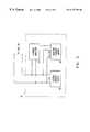
- FIG. 1is a schematic representation of an object tracking system operative in accordance with a preferred embodiment of the present invention
- FIG. 2is a schematic representation of a radiator coil in accordance with a preferred embodiment of the present invention.
- FIG. 3is a schematic representation of coil driver circuitry in accordance with another preferred embodiment of the present invention.
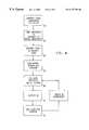
- FIG. 4is a flow chart illustrating schematically a method of object tracking in accordance with a preferred embodiment of the present invention.
- FIG. 1illustrates schematically a system for tracking a probe 20 , such as a catheter for medical use, operative in accordance with preferred embodiment of the present invention.
- a probe 20such as a catheter for medical use
- the systemcomprises a plurality of radiator coils 22 , 24 and 26 . These coils generate respective magnetic fields H 1 , H 2 and H 3 , at respective frequencies ⁇ 1 , ⁇ 2 and ⁇ 3 , in the vicinity of probe 20 .
- the probefurther includes sensor coils 27 , 28 and 29 , which generate electrical current signals in response to the magnetic fields, wherein the signals comprise components at frequencies ⁇ 1 , ⁇ 2 and ⁇ 3 , whose respective amplitudes are dependent on the position and orientation of probe 20 .
- the systemfurther comprises driver circuitry 30 , 32 and 33 , coupled to each of the radiator coils, which drives coils 22 , 24 and 26 at respective driving frequencies ⁇ 1 , ⁇ 2 and ⁇ 3 .
- the signals generated by sensor coils 27 , 28 and 29are preferably processed by signal processing circuitry 34 and then used by computer 36 to calculate position and orientation coordinates of probe 20 .
- FIG. 1shows three radiator coils 22 , 24 and 26 and three sensor coils 27 , 28 and 29 in a probe 20 . It will be understood, however, that the present invention is equally applicable to tracking systems comprising two, four or more radiator coils and one, two or more sensor coils. The present invention may be used in tracking other types of objects, as well.
- the signals generated by sensor coils 27 , 28 and 29 at frequency ⁇ 1are proportional to the amplitude of the time derivative of the projection of magnetic flux due to field H 1 at probe 20 along each of the respective axes of the sensor coils.
- the signals generated at frequencies ⁇ 2 and ⁇ 3are similarly proportional to the projections of H 2 and H 3 . Since the direction and amplitude of the magnetic field due to a single such radiator coil can be calculated easily using methods known in the art, the sensor coil signals due to a single radiator coil may be directly related to the sensor coil's distance from and orientation relative to the radiator coil.
- magnetic field H 1 generated by radiator coil 22is not limited in space to an immediate vicinity of probe 20 , but also has a non-zero amplitude in a vicinity of coils 24 and 26 .
- the magnetic flux ⁇ 2 through coil 24 due to current I 1 flowing in coil 22may be expressed as:
- the signals generated by sensor coils 27 , 28 and 29 at frequency ⁇ 1will include both a position signal component due to H 1 and a parasitic signal component due to H 12 , which may introduce errors of up to 1% in determination of the position of probe 20 .
- Additional parasitic signal components at frequency ⁇ 1will be introduced by mutual inductance in coil 26 and any other radiator coils.
- sensor coil signals at frequencies ⁇ 2 and ⁇ 3will also include parasitic components.
- one or more shimming coils 40are adjacent to radiator coil 24 , and preferably interwound therewith.
- Driver circuitry 32drives coil 24 with current I 2 at the coil's driving frequency ⁇ 2 .
- circuitry 32further drives shimming coil 40 with current I 2 (1) at frequency ⁇ 1 , wherein this current causes a magnetic field H 2 (1) to be generated along the axis of coil 24 which is equal in amplitude and 180° out of phase with magnetic field H 12 . Consequently, mutually-induced current I 12 will be substantially canceled out by an equal and opposite current induced due to field H 2 (1) .
- FIG. 2 and the foregoing explanationrelate only to a single shimming coil, driven at a single frequency, it will be understood that in preferred embodiments of the present invention, each of coils 22 , 24 and 26 will be interwound with at least one shimming coil, driven with appropriate currents and frequencies so as to substantially cancel out mutually-induced currents due to all other coils.
- FIG. 3illustrates schematically an alternative preferred embodiment of the present invention, wherein driver circuitry 32 is adapted to drive coil 24 so as to substantially cancel mutually induced currents.
- Circuitry 32comprises system current supply 50 , which drives coil 24 at its driving frequency ⁇ 2 , and adaptive current supply 52 , which generates current to drive coil 24 at the respective frequencies of coils 22 and 26 , ⁇ 1 and ⁇ 3 , with amplitudes and phases determined by current analyzer 54 .
- the current analyzersamples the current in coil 24 , using methods known in the art, and separates the sampled current into frequency components.
- Analyzer 54causes adaptive supply 52 to adjust the amplitudes and phases of the generated ⁇ 1 and ⁇ 3 currents so as to minimize the components sensed at frequencies ⁇ 1 and ⁇ 3 in the sampled current from coil 24 .
- the generated ⁇ 1 and ⁇ 3 currentsare substantially equal in amplitude to and 180° out of phase with the mutually induced currents I 12 and I 32 . It will be understood that coils 22 and 26 are driven by similar adaptive driver circuitry.
- signal processing circuitry 34 and computer 36function to determine amplitudes and phases of the parasitic signal components generated by sensor coils 27 , 28 and 29 due to mutual inductance among the radiator coils, and correct the determination of the position of probe 20 to account for the parasitic components.
- the amplitude and phase of the magnetic field due to each of the coilsis found using a harmonic detection method.
- Nis the number of sampling points.
- signal samplingis thus synchronized with the magnetic field frequencies. If N is a small number, then the sampling is preferably synchronized with the magnetic field, and may preferably be synchronized to take place at the peak of the periodic magnetic field.
- the signals generated by the jth sensor coilcomprise frequency components whose respective amplitudes Uij and Vij, at radiator coil frequency ⁇ i , may be expressed as follows:
- U ijA ij ⁇ ⁇ cos ⁇ ⁇ ⁇ i + ⁇ k ⁇ i 3 ⁇ ⁇ A ijk m ⁇ cos ⁇ ⁇ ⁇ ik m ( 8 )
- V ijA ij ⁇ ⁇ sin ⁇ ⁇ ⁇ i + ⁇ k ⁇ i 3 ⁇ ⁇ A ijk m ⁇ sin ⁇ ⁇ ⁇ ik m ( 9 )
- Aij and ⁇ irepresent the amplitude and phase, respectively, of the position signal components received from sensor coil 28 (here identified as the jth sensor coil) at frequency ⁇ i due to the magnetic field of the ith radiator coil, disregarding mutual inductance effects.
- Aijk m and ⁇ ik mare the respective amplitudes and phases of the parasitic signal components generated by the jth sensor coil at frequency ⁇ i , due to mutual inductance between the ith and kth radiator coils.
- the signals received from the coilare preferably processed using the method shown in FIG. 4 .
- the amplitudes of these signals Aijare then determined ( 62 ), assuming that mutual inductance effects are insignificant, i.e., that all Aijk m are zero.
- Phases ⁇ i and ⁇ ik mwhich are dependent only on the radiator coils, are derived by measuring the respective radiator coil phases ( 64 ).
- the amplitudes Aijare then used to estimate the position and orientation of coils 27 , 28 and 29 ( 66 ), as described, for example, in unpublished PCT patent application No. PCT/US95/01103.
- the theoretical values of aijk mare then calculated for the estimated position of the sensor coils ( 68 ).
- the parasitic magnetic fields generated due to mutual inductance among the radiator coils, Hikare determined at the sensor coils' estimated position. These parasitic fields are transformed from the coordinate frame of the radiator coils to that of the sensor coils, based on the projections of the parasitic fields along the respective axes of the sensor coils.
- the field projectionsare used to calculate theoretical amplitudes of parasitic signal components generated by the sensor coils, using the relationship:
- Various methodsmay be used to determine the amplitude and direction of the parasitic magnetic fields Hik at the position of the sensor coils.
- mutual inductances among the coils and the resultant magnetic fieldsare calculated theoretically from geometrical considerations, using methods well known in the art.
- the mutual inductance of a pair of radiator coilsis determined by activating the driver circuitry of one of the coils, so as to generate a magnetic field at its driving frequency, and then measuring electrical current flowing in the other coil at this frequency. These measured mutual inductances are then used to calculate the resultant parasitic magnetic fields, as explained above.
Landscapes
- Physics & Mathematics (AREA)
- Engineering & Computer Science (AREA)
- Remote Sensing (AREA)
- Life Sciences & Earth Sciences (AREA)
- General Physics & Mathematics (AREA)
- Electromagnetism (AREA)
- Environmental & Geological Engineering (AREA)
- Geology (AREA)
- General Life Sciences & Earth Sciences (AREA)
- Geophysics (AREA)
- Measurement Of Length, Angles, Or The Like Using Electric Or Magnetic Means (AREA)
Abstract
Description
This application claims the benefit of U.S. Provisional Patent Application No. 60/014,084, filed Mar. 26, 1996, which is incorporated herein by reference.
The present invention relates generally to apparatus for generating and detecting electromagnetic fields, and specifically to non-contact, electromagnetic methods and devices for tracking the position and orientation of an object.
Non-contact electromagnetic tracking systems are well known in the art, with a wide range of applications.
For example, U.S. Pat. No. 4,054,881 describes a tracking system using three coils to generate electromagnetic fields in the vicinity of the object. The fields generated by these three coils are distinguished from one another by open loop multiplexing of time, frequency or phase. The signal currents flowing in three orthogonal sensor coils are used to determine the object's position, based on an iterative method of computation.
U.S. Pat. No. 5,391,199, filed Jul. 20, 1993, which is assigned to the assignee of the present application and whose disclosure is incorporated herein by reference, describe a system for generating three-dimensional location information regarding a medical probe or catheter. A seconsr coil is placed in the catheter and generates signals in response to externally applied magnetic fields. The magnetic fields are generated by three radiator coils, fixed to an external reference frame in known, mutually spaced locations. The amplitudes of the signals generated in response to each of the radiator coil fields are detected and used to compute the location of the sensor coil. Each radiator coil is preferably driven by driver circuitry to generate a field at a known frequency, distinct from that of other radiator coils, so that the signals generated by the sensor coil may be separated by frequency into components corresponding to the different radiator coils.
Unpublished PCT patent application No. PCT/US95/01103, filed Jan. 24, 1995, which is assigned to the assignee of the present application and whose disclosure is incorporated herein by reference, describes a system that generates six-dimensional position and orientation information regarding the tip of a catheter. This system uses a plurality of non-concentric sensor coils adjacent to a locatable site in the catheter, for example near its distal end, and a plurality of radiator coils fixed in an external reference frame. These coils generate signals in response to magnetic fields generated by the radiator coils, which signals allow for the computation of six location and orientation coordinates. As in the case of the '539 patent application described above, the radiator coils operate simultaneously at different frequencies, for example at 1000, 2000 and 3000 Hz, respectively.
The above tracking systems rely on separation of position-responsive signals into frequency components, wherein each such component is assumed to correspond uniquely to a single radiator coil, in a known position, radiating in a narrow, well-defined frequency band. In practice, however, the radiator coils also generate magnetic fields at the frequencies outside the desired bands, for example due to mutual inductance effects. These mutually-induced fields lead to errors in determining the position of the object being tracked.
It is an object of the present invention to provide improved electromagnetic radiator coils and driver circuitry therefor, for use in conjunction with object tracking systems, so as to increase the accuracy of object tracking.
It is a further object of the present invention to provide magnetic field generator coils and associated driver circuitry that generate fields of having narrow bandwidths in the frequency domain.
In one aspect of the present invention, narrowed field bandwidth is achieved by eliminating mutual inductance effects among a plurality of coils, which generate magnetic fields at different frequencies.
Still a further object of the present invention is to provide a method for improving the accuracy of a position determined by an object tracking system, by correcting the position determination so as to account for mutual inductance effects.
In preferred embodiments of the present invention, a plurality of radiator coils generate magnetic fields at a plurality of different respective driving frequencies.
In some preferred embodiments of the present invention, one or more additional shimming coils are adjacent to each of the radiator coils. Preferably the shimming coils are interwound with windings of the radiator coils. The shimming coils of each radiator coil are driven by driver circuitry so as to generate magnetic fields that are substantially equal in amplitude and frequency, and opposite in direction, to magnetic field components induced along the axis of that radiator coil by other radiator coils.
In other preferred embodiments of the present invention, driver circuitry is associated with each of the coils and generates electrical driver currents therein, wherein for each coil the current comprises a major component at the coil's respective driving frequency, and minor components at other frequencies. The minor components are substantially equal in amplitude and frequency and 180° out of phase with currents induced in the coil due to magnetic fields generated by other radiator coils, so as to substantially cancel the effect of the induced currents.
In one such preferred embodiment of the present invention, driver circuitry includes sensing apparatus, which measures the amplitude, frequency and phase of induced currents in a coil. The driver circuitry further includes an adaptive current supply, which receives the amplitude, frequency and phase data measured by the sensing apparatus, and generates the out-of-phase minor current components to substantially cancel the effect of the induced currents.
In still other preferred embodiments of the present invention, driver circuitry comprises ideal current sources, which function to maintain a constant current in each of the coils at its fixed, respective driving frequency.
In other preferred embodiments of the present invention, an object tracking system comprises one or more sensor coils adjacent to a locatable point on an object being tracked, and a plurality of radiator coils, which generate magnetic fields when driven by driver circuitry at a plurality of different respective driving frequencies in a vicinity of the object. The sensor coils generate signals responsive to the magnetic fields, which signals are received by signal processing circuitry and analyzed by a computer or other processor. The signals include position signal components responsive to the magnetic fields generated by the radiator coils at their respective driving frequencies, and parasitic signal components responsive to magnetic fields generated due to mutual inductance among the radiator coils. The computer processes the signals to separate the position signal components from the parasitic components, preferably using an iterative method, as described below, and uses the position signal components to determine the position of the object.
In one such preferred embodiment of the present invention, the signals, including position components and parasitic components, are used to compute approximate location and orientation coordinates of the object. The strengths of magnetic fields generated at this location by the radiator coils due to mutual inductance effects among the coils are then calculated theoretically, and are used to estimate theoretical strengths of the parasitic components. Corrected signals are calculated by subtracting these theoretical parasitic component strengths from the signals, and these corrected signals are used to calculate corrected location and orientation of the object. These steps are repeated iteratively until the calculation of the corrected location and orientation converges.
In some preferred embodiments of the present invention, mutual inductances among radiator coils in an object tracking system are determined by empirical measurement, using methods known in the art. Thus, for example, the mutual inductance of a pair of radiator coils is determined by activating the driver circuitry of a first coil, so as to generate a magnetic field at a driving frequency thereof, and then measuring the electrical current flowing in a second coil. These measured mutual inductances are then used to estimate the theoretical strengths of the parasitic components for calculation of the corrected signals, in accordance with the method described above. Alternatively, the measured mutual inductances may be used in controlling driver circuitry for generating electrical driver currents 180° out of phase with mutually induced currents.
There is thus provided, in accordance with a preferred embodiment of the present invention, apparatus for generating magnetic fields, comprising a plurality of radiator coils and driver circuitry coupled thereto, which drives the coils so as to generate magnetic fields at a plurality of driving frequencies, wherein each of the plurality of radiator coils generates a field substantially only at a single, respective driving frequency.
Preferably the apparatus for generating magnetic fields comprises circuitry associated with at least one of said plurality of radiator coils for substantially eliminating magnetic fields generated by the at least one coil in response to fields generated by the other coils.
The circuitry for eliminating magnetic fields preferably comprises one or more shimming coils, which are preferably interwound with the at least one of said plurality of radiator coils. Furthermore, the driver circuitry preferably drives one of the one or more shimming coils associated with the at least one of said plurality of radiator coils at the respective driving frequency of another one of said plurality of radiator coils.
Preferably the circuitry further includes a current analyzer, coupled to the adaptive current supply, wherein the current analyzer measures parasitic electrical current flowing in the at least one of said plurality of radiator coils at the respective driving frequency of another one of said plurality of radiator coils, and causes the adaptive current supply to adjust the generated current so as to minimize the parasitic electrical current.
There is further provided, in accordance with a preferred embodiment of the present invention, a method for generating magnetic field having a desired narrow frequency band, comprising: driving a radiator coil with electrical current at the desired frequency; analyzing the current flowing in the coil to measure induced current components at one or more undesired frequencies; and adaptively driving the radiator coil with correction current components at the one or more undesired frequencies, wherein the correction current components are substantially equal in amplitude and opposite in phase to the induced current components measured at the respective one or more undesired frequencies.
There is further provided, in accordance with a preferred embodiment of the present invention, a method for tracking an object, comprising generating a plurality of magnetic fields having a plurality of respective desired narrow frequency bands, in accordance with the preceding method, in a vicinity of an object being tracked; placing one or more sensor coils at a locatable site on the object; receiving signals generated by the sensor coils in response to the magnetic fields; and analyzing the signals to determine position and orientation coordinates of the object.
There is further provided, in accordance with a preferred embodiment of the present invention, a method for tracking an object, comprising: driving a plurality of radiator coils with electrical currents at a plurality of respective frequencies, so as to generate magnetic fields in a vicinity of an object being tracked; placing one or more sensor coils at a locatable site on the object; receiving signals generated by the sensor coils in response to the magnetic fields; analyzing the signals to determine uncorrected position and orientation coordinates of the object, and correcting the position and orientation coordinates to account for errors due to mutual inductance among the plurality of radiator coils.
Preferably, position and orientation coordinates are corrected by the steps of: determining parasitic magnetic fields that would be generated at the uncorrected position of the object due to mutual inductance; computing parasitic signal components that would be generated by the sensor coils in response to the parasitic magnetic fields; calculating corrected signals by subtracting the parasitic signal components from the signals received from the sensor coils; and analyzing the corrected signals to determine corrected position and orientation coordinates.
Preferably, determining the parasitic magnetic fields comprises analyzing the current flowing in the plurality of radiator coils to measure induced current components at undesired frequencies.
Alternatively, determining the parasitic magnetic fields comprises calculating theoretically the mutual inductance among the plurality of radiator coils.
There is therefore provided, in accordance with a preferred embodiment of the present invention, apparatus for generating magnetic fields, including:
a plurality of radiator coils; and
driver circuitry coupled thereto, which drives the coils so as to generate magnetic fields at a plurality of driving frequencies,
wherein each of the plurality of radiator coils generates a field substantially only at a single, respective driving frequency.
Preferably the apparatus includes circuitry associated with at least one of the plurality of radiator coils for substantially eliminating magnetic fields generated by the at least one coil in response to fields generated by the other coils. This circuitry preferably includes one or more shimming coils, which are preferably interwound with the at least one of said plurality of radiator coils.
Preferably the driver circuitry further drives one of the one or more shimming coils associated with the at least one of the plurality of radiator coils at the respective driving frequency of another one of the plurality of radiator coils.
Preferably the circuitry for eliminating includes an adaptive current supply, which generates electrical current in the at least one of the plurality of radiator coils at the respective driving frequency of another one of the plurality of radiator coils.
Preferably the circuitry for eliminating further includes a current analyzer, coupled to the adaptive current supply, which current analyzer measures parasitic electrical current flowing in the at least one of the plurality of radiator coils at the respective driving frequency of another one of the plurality of radiator coils, and causes the adaptive current supply to adjust the generated current so as to minimize the parasitic electrical current.
Preferably the driver circuitry is adapted to maintain a constant current in each of the plurality of radiator coils at the single, respective driving frequency thereof.
There is further provided, in accordance with a preferred embodiment of the present invention, a method for generating a magnetic field having a desired narrow frequency band, including the following steps:
driving a radiator coil with electrical current at a frequency in the desired narrow frequency band;
analyzing the current flowing in the coil to measure inducted current components at one or more undesired frequencies; and
adaptively driving the radiator coil with correction current components at the one or more undesired frequencies, wherein the correction current components are substantially equal in amplitude and opposite in phase to the induced current components measured at the respective one or more undesired frequencies.
There is also provided, in accordance with a preferred embodiment of the present invention, a method for tracking an object, including the following steps:
generating a plurality of magnetic fields having a plurality of respective desired narrow frequency bands, in accordance with the preceding method, in a vicinity of an object being tracked;
placing one or more sensor coils at a locatable site on the object;
receiving signals generated by the sensor coils in response to the magnetic fields; and
analyzing the signals to determine position and orientation coordinates of the object.
There is further provided, in accordance with a preferred embodiment of the present invention, a method for tracking an object including the following steps:
driving a plurality of radiator coils with electrical currents at a plurality of respective frequencies, so as to generate magnetic fields in a vicinity of an object being tracked;
placing one or more sensor coils at a locatable site on the object;
receiving signals generated by the sensor coils in response to the magnetic fields;
analyzing the signals to determine uncorrected position and orientation coordinates of the object; and
correcting the position and orientation coordinates to account for errors due to mutual inductance among the plurality of radiator coils.
Preferably the position and orientation coordinates are corrected by the steps of:
determining parasitic magnetic fields that would be generated at the uncorrected position of the object due to mutual inductance;
computing parasitic signal components that would be generated by the sensor coils in response to the parasitic magnetic fields;
calculating corrected signals by subtracting the parasitic signal components from the signals received from the sensor coils; and
analyzing the corrected signals to determine corrected position and orientation coordinates.
Preferably the parasitic magnetic fields are determined by analyzing the current flowing in the plurality of radiator coils to measure induced current components at undesired frequencies.
Alternatively, the parasitic magnetic fields are determined calculating theoretically the mutual inductance among the plurality of radiator coils.
The present invention will be more fully understood from the following detailed description of the preferred embodiments thereof, taken together with the drawings in which:
FIG. 1 is a schematic representation of an object tracking system operative in accordance with a preferred embodiment of the present invention;
FIG. 2 is a schematic representation of a radiator coil in accordance with a preferred embodiment of the present invention;
FIG. 3 is a schematic representation of coil driver circuitry in accordance with another preferred embodiment of the present invention; and
FIG. 4 is a flow chart illustrating schematically a method of object tracking in accordance with a preferred embodiment of the present invention.
Reference is now made to FIG. 1, which illustrates schematically a system for tracking aprobe 20, such as a catheter for medical use, operative in accordance with preferred embodiment of the present invention. As described in U.S. Pat. No. 5,391,199, to Ben-Haim, and in unpublished PCT patent application No. PCT/US95/01103, filed Jan. 24, 1995, which are assigned to the assignee of the present application and whose disclosures are incorporated herein by reference, the system comprises a plurality of radiator coils22,24 and26. These coils generate respective magnetic fields H1, H2and H3, at respective frequencies ω1, ω2and ω3, in the vicinity ofprobe 20. The probe further includes sensor coils27,28 and29, which generate electrical current signals in response to the magnetic fields, wherein the signals comprise components at frequencies ω1, ω2and ω3, whose respective amplitudes are dependent on the position and orientation ofprobe 20.
The system further comprisesdriver circuitry sensor coils signal processing circuitry 34 and then used bycomputer 36 to calculate position and orientation coordinates ofprobe 20.
For the sake of clarity, FIG. 1 shows threeradiator coils sensor coils probe 20. It will be understood, however, that the present invention is equally applicable to tracking systems comprising two, four or more radiator coils and one, two or more sensor coils. The present invention may be used in tracking other types of objects, as well.
In the absence of mutual inductance effects, the signals generated bysensor coils probe 20 along each of the respective axes of the sensor coils. The signals generated at frequencies ω2and ω3are similarly proportional to the projections of H2and H3. Since the direction and amplitude of the magnetic field due to a single such radiator coil can be calculated easily using methods known in the art, the sensor coil signals due to a single radiator coil may be directly related to the sensor coil's distance from and orientation relative to the radiator coil.
In practice, however, magnetic field H1generated byradiator coil 22 is not limited in space to an immediate vicinity ofprobe 20, but also has a non-zero amplitude in a vicinity ofcoils coil 24 due to current I1flowing incoil 22 may be expressed as:


Sincedriver circuitry coil 24, having amplitude given by:

Current I12flowing inradiator coil 24 will cause a parasitic magnetic field H12to be generated at frequency ω1, whose amplitude will be approximately proportional to the ratio M12/L which ω1≈ω2. M12depends on geometrical factors and on the number of turns in each of the coils. It can be shown (see, for example J. D. Jackson,Classical Electrodynamics, Second Edition, page 263) that for the two coplanar current loops of radius a, mutually spaced by a distance R:

Forcoils coil 24, we may integrate equation (5) to find the mutual inductance of the coils:

Thus, for example, in a tracking system such as those described in U.S. Pat. No. 5,391,199 and in unpublished PCT patent application No. PCT/US95/01103, wherein coils22 and24 have inner radii of 25 mm and outer radii of approximately 60 mm, and are mutually spaced by 39 cm, it will be observed that I12=0.0025(ω1/ω2)I1, which could lead to an error of 0.5% when ω1=2ω2. Thus, the signals generated bysensor coils probe 20. Additional parasitic signal components at frequency ω1will be introduced by mutual inductance incoil 26 and any other radiator coils. Similarly, sensor coil signals at frequencies ω2and ω3will also include parasitic components.
For this reason, in a preferred embodiment of the present invention shown in FIG. 2, one or more shimming coils40 are adjacent toradiator coil 24, and preferably interwound therewith.Driver circuitry 32drives coil 24 with current I2at the coil's driving frequency ω2.circuitry 32 furtherdrives shimming coil 40 with current I2(1)at frequency ω1, wherein this current causes a magnetic field H2(1)to be generated along the axis ofcoil 24 which is equal in amplitude and 180° out of phase with magnetic field H12. Consequently, mutually-induced current I12will be substantially canceled out by an equal and opposite current induced due to field H2(1).
Although, for the sake of clarity, FIG.2 and the foregoing explanation relate only to a single shimming coil, driven at a single frequency, it will be understood that in preferred embodiments of the present invention, each of coils22,24 and26 will be interwound with at least one shimming coil, driven with appropriate currents and frequencies so as to substantially cancel out mutually-induced currents due to all other coils.
FIG. 3 illustrates schematically an alternative preferred embodiment of the present invention, whereindriver circuitry 32 is adapted to drivecoil 24 so as to substantially cancel mutually induced currents.Circuitry 32 comprises systemcurrent supply 50, which drivescoil 24 at its driving frequency ω2, and adaptivecurrent supply 52, which generates current to drivecoil 24 at the respective frequencies ofcoils current analyzer 54. The current analyzer samples the current incoil 24, using methods known in the art, and separates the sampled current into frequency components.Analyzer 54 causesadaptive supply 52 to adjust the amplitudes and phases of the generated ω1and ω3currents so as to minimize the components sensed at frequencies ω1and ω3in the sampled current fromcoil 24. Typically the generated ω1and ω3currents are substantially equal in amplitude to and 180° out of phase with the mutually induced currents I12and I32. It will be understood that coils22 and26 are driven by similar adaptive driver circuitry.
In other preferred embodiments of the present invention,signal processing circuitry 34 andcomputer 36 function to determine amplitudes and phases of the parasitic signal components generated bysensor coils probe 20 to account for the parasitic components.
In one such preferred embodiment of the present invention, the amplitude and phase of the magnetic field due to each of the coils is found using a harmonic detection method. In accordance with this method, the signals are sampled so that an integer number of periods of each of the signals are measured, i.e., 2πƒs/ω=N, where fsis the sampling frequency, and N is the number of sampling points. In this way, signal sampling is thus synchronized with the magnetic field frequencies. If N is a small number, then the sampling is preferably synchronized with the magnetic field, and may preferably be synchronized to take place at the peak of the periodic magnetic field. The signals thus obtained at a frequency ω may be expressed as:

In the presence of mutual inductance, the signals generated by the jth sensor coil comprise frequency components whose respective amplitudes Uij and Vij, at radiator coil frequency ωi, may be expressed as follows:

In equations (8) and (9), Aij and φirepresent the amplitude and phase, respectively, of the position signal components received from sensor coil28 (here identified as the jth sensor coil) at frequency ωidue to the magnetic field of the ith radiator coil, disregarding mutual inductance effects. Aijkmand φikmare the respective amplitudes and phases of the parasitic signal components generated by the jth sensor coil at frequency ωi, due to mutual inductance between the ith and kth radiator coils.
In order to correctly determine the position of sensor coils27,28 and29 andprobe 20, the signals received from the coil are preferably processed using the method shown in FIG.4. First (60) the signals are separated into components Uij and Vij at frequencies ω1, ω2and ω3using methods known in the art, such as harmonic detection. The amplitudes of these signals Aij are then determined (62), assuming that mutual inductance effects are insignificant, i.e., that all Aijkmare zero. Phases Φiand Φikm, which are dependent only on the radiator coils, are derived by measuring the respective radiator coil phases (64). The amplitudes Aij are then used to estimate the position and orientation ofcoils
The theoretical values of aijkmare then calculated for the estimated position of the sensor coils (68). To perform this calculation, the parasitic magnetic fields generated due to mutual inductance among the radiator coils, Hik, are determined at the sensor coils' estimated position. These parasitic fields are transformed from the coordinate frame of the radiator coils to that of the sensor coils, based on the projections of the parasitic fields along the respective axes of the sensor coils. The field projections are used to calculate theoretical amplitudes of parasitic signal components generated by the sensor coils, using the relationship:

where the three values of {overscore (A)}ipkmare the theoretical signal amplitudes in the radiator coils' frame of reference, and Mjp are the elements of the orientation matrix.
Various methods may be used to determine the amplitude and direction of the parasitic magnetic fields Hik at the position of the sensor coils. In one preferred embodiment of the present invention, mutual inductances among the coils and the resultant magnetic fields are calculated theoretically from geometrical considerations, using methods well known in the art. In an alternative preferred embodiment, the mutual inductance of a pair of radiator coils is determined by activating the driver circuitry of one of the coils, so as to generate a magnetic field at its driving frequency, and then measuring electrical current flowing in the other coil at this frequency. These measured mutual inductances are then used to calculate the resultant parasitic magnetic fields, as explained above.
Finally, the theoretical Aijkmcoefficients are substituted back into equations (8) and (9) to determine corrected values of the nine Aij elements (70), and these values are used to correct the position and orientation coordinates of the probe (72). Steps (68), (70) and (72) are preferably repeated iteratively until the position and orientation coordinates of the probe converge.
It will be understood that while the above method has been described with reference to a system comprising three radiator coils and three sensor coils, it may equally be applied to other electromagnetic object tracking system, using greater or fewer numbers of coils or antennae.
Claims (15)
1. Apparatus for tracking an object by generating magnetic fields, comprising:
a plurality of radiator coils;
driver circuitry coupled thereto, which drives the coils so as to generate magnetic fields at a plurality of driving frequencies,
wherein each of the plurality of radiator coils generates a field substantially only at a single, respective driving frequency; and
circuitry associated with at least one of said plurality of radiator coils for substantially eliminating magnetic fields generated by the at least one coil in response to fields generated by the other coils.
2. Apparatus in accordance with claim1, wherein said circuitry for eliminating comprises one or more shimming coils.
3. Apparatus in accordance with claim2, wherein the one or more shimming coils are interwound with the at least one of said plurality of radiator coils.
4. Apparatus in accordance with claim3, wherein the driver circuitry further drives one of the one or more shimming coils associated with the at least one of said plurality of radiator coils at the respective frequency of another one of said plurality of radiator coils.
5. Apparatus in accordance with claim4, wherein the circuitry for eliminating includes an adaptive current supply.
6. Apparatus in accordance with claim5, wherein the adaptive current supply generates electrical current in the at least one of said plurality of radiator coils at the respective driving frequency of another one of said plurality of radiator coils.
7. Apparatus in accordance with claim6, wherein the circuitry for eliminating further includes a current analyzer coupled to the adaptive current supply.
8. Apparatus in accordance with claim7, wherein the current analyzer measures parasitic electrical current flowing in the at least one of said plurality of radiator coils at the respective driving frequency of another one of said plurality of radiator coils, and causes the adaptive current supply to adjust the generated current so as to minimize the parasitic electrical current.
9. Apparatus in accordance with claim1, wherein the driver circuitry maintains a constant current in each of the plurality of radiator coils at the single, respective driving frequency thereof.
10. A method for tracking an object by generating a magnetic field having a desired narrow frequency band, comprising:
driving a radiator coil with electrical current at a frequency in the desired narrow frequency band;
analyzing the current flowing in the coil to measure induced current components at one or more undesired frequencies; and
adaptively driving the radiator coil with correction current components at the one or more undesired frequencies, wherein the correction current components are substantially equal in amplitude and opposite in phase to the induced current components measured at the respective one or more undesired frequencies.
11. A method in accordance with claim10, comprising:
generating a plurality of magnetic fields having a plurality of respective desired narrow frequency bands in a vicinity of an object being tracked;
placing one or more sensor coils at a locatable site on the object;
receiving signals generated by the sensor coils in response to the magnetic fields; and
analyzing the signals to determine position and orientation coordinates of the object.
12. A method for tracking an object, comprising:
driving a plurality of radiator coils with electrical currents at a plurality of respective frequencies, so as to generate magnetic fields in a vicinity of an object being tracked;
placing one or more sensor coils at a locatable site on the object;
receiving signals generated by the sensor coils in response to the magnetic fields;
analyzing the signals to determine uncorrected position and orientation coordinates of the object; and
correcting the position and orientation coordinates to account for errors due to mutual inductance among the plurality of radiator coils.
13. A method in accordance with claim12, wherein the position and orientation coordinates are corrected by the steps of:
determining parasitic magnetic fields that would be generated at the uncorrected position of the object due to mutual inductance;
computing parasitic signal components that would be generated by the sensor coils in response to the parasitic magnetic fields;
calculating corrected signals by subtracting the parasitic signal components from the signals received from the sensor coils; and
analyzing the corrected signals to determine corrected position and orientation coordinates.
14. A method in accordance with claim13, wherein determining the parasitic magnetic fields comprises analyzing the current flowing in the plurality of radiator coils to measure induced current components at undesired frequencies.
15. A method in accordance with claim13, wherein determining the parasitic magnetic fields comprises calculating theoretically the mutual inductance among the plurality of radiator coils.
Applications Claiming Priority (3)
| Application Number | Priority Date | Filing Date | Title |
|---|---|---|---|
| US1408496P | 1996-03-26 | 1996-03-26 | |
| PCT/IL1997/000100WO1997036143A1 (en) | 1996-03-26 | 1997-03-18 | Mutual induction correction |
| US12554499P | 1999-03-19 | 1999-03-19 |
Related Child Applications (1)
| Application Number | Title | Priority Date | Filing Date |
|---|---|---|---|
| US09/702,974Continuation-In-PartUS6498477B1 (en) | 1999-03-19 | 2000-10-31 | Mutual crosstalk elimination in medical systems using radiator coils and magnetic fields |
Publications (1)
| Publication Number | Publication Date |
|---|---|
| US6177792B1true US6177792B1 (en) | 2001-01-23 |
Family
ID=26685637
Family Applications (1)
| Application Number | Title | Priority Date | Filing Date |
|---|---|---|---|
| US09/125,544Expired - LifetimeUS6177792B1 (en) | 1996-03-26 | 1997-03-18 | Mutual induction correction for radiator coils of an objects tracking system |
Country Status (1)
| Country | Link |
|---|---|
| US (1) | US6177792B1 (en) |
Cited By (164)
| Publication number | Priority date | Publication date | Assignee | Title |
|---|---|---|---|---|
| US20040107070A1 (en)* | 2002-03-27 | 2004-06-03 | Anderson Peter T. | Magnetic tracking system |
| EP1481636A1 (en)* | 2003-05-29 | 2004-12-01 | Biosense Webster, Inc. | Apparatus, method and software for tracking an object |
| US20040239314A1 (en)* | 2003-05-29 | 2004-12-02 | Assaf Govari | Hysteresis assessment for metal immunity |
| US20050003757A1 (en)* | 2003-07-01 | 2005-01-06 | Anderson Peter Traneus | Electromagnetic tracking system and method using a single-coil transmitter |
| US20050012597A1 (en)* | 2003-07-02 | 2005-01-20 | Anderson Peter Traneus | Wireless electromagnetic tracking system using a nonlinear passive transponder |
| EP1502544A1 (en)* | 2003-07-31 | 2005-02-02 | Biosense Webster, Inc. | Detection of metal disturbance in a magnetic tracking system |
| US20050062469A1 (en)* | 2003-09-23 | 2005-03-24 | Anderson Peter Traneus | System and method for hemisphere disambiguation in electromagnetic tracking systems |
| US20050104776A1 (en)* | 2003-11-14 | 2005-05-19 | Anderson Peter T. | Electromagnetic tracking system and method using a three-coil wireless transmitter |
| US20050154284A1 (en)* | 2003-12-31 | 2005-07-14 | Wright J. N. | Method and system for calibration of a marker localization sensing array |
| US20060048081A1 (en)* | 2004-08-31 | 2006-03-02 | Texas Instruments Incorporated | System and method for modeling an integrated circuit system |
| US20060055712A1 (en)* | 2004-08-24 | 2006-03-16 | Anderson Peter T | Method and system for field mapping using integral methodology |
| US20060106292A1 (en)* | 2003-09-24 | 2006-05-18 | General Electric Company | System and method for employing multiple coil architectures simultaneously in one electromagnetic tracking system |
| EP1743575A2 (en) | 2005-07-15 | 2007-01-17 | Biosense Webster, Inc. | Hybrid magnetic-based and impedance-based position sensing |
| US20070085528A1 (en)* | 2005-10-19 | 2007-04-19 | Assaf Govari | Metal immunity in a reverse magnetic system |
| US20070129629A1 (en)* | 2005-11-23 | 2007-06-07 | Beauregard Gerald L | System and method for surgical navigation |
| US20070161888A1 (en)* | 2005-12-30 | 2007-07-12 | Sherman Jason T | System and method for registering a bone of a patient with a computer assisted orthopaedic surgery system |
| US20070163367A1 (en)* | 2005-12-30 | 2007-07-19 | Sherman Jason T | Magnetic sensor array |
| US20070167741A1 (en)* | 2005-12-30 | 2007-07-19 | Sherman Jason T | Apparatus and method for registering a bone of a patient with a computer assisted orthopaedic surgery system |
| US20070167703A1 (en)* | 2005-12-30 | 2007-07-19 | Sherman Jason T | Method for determining a position of a magnetic source |
| US20070185397A1 (en)* | 2006-02-09 | 2007-08-09 | Assaf Govari | Two-stage calibration of medical probes |
| US20070208251A1 (en)* | 2006-03-02 | 2007-09-06 | General Electric Company | Transformer-coupled guidewire system and method of use |
| US20080079421A1 (en)* | 2006-08-15 | 2008-04-03 | General Electric Company | Multi-sensor distortion mapping method and system |
| US20080154127A1 (en)* | 2006-12-21 | 2008-06-26 | Disilvestro Mark R | Method and system for registering a bone of a patient with a computer assisted orthopaedic surgery system |
| US20080246472A1 (en)* | 2005-09-07 | 2008-10-09 | Koninklijke Philips Electronics, N.V. | System and Method for Inductively Measuring the Bio-Impedance of a Conductive Tissue |
| US20080306380A1 (en)* | 2006-02-09 | 2008-12-11 | Yochai Parchak | Shielding of catheter handle |
| US7471202B2 (en) | 2006-03-29 | 2008-12-30 | General Electric Co. | Conformal coil array for a medical tracking system |
| US20090062739A1 (en)* | 2007-08-31 | 2009-03-05 | General Electric Company | Catheter Guidewire Tracking System and Method |
| US7532997B2 (en) | 2006-04-17 | 2009-05-12 | General Electric Company | Electromagnetic tracking using a discretized numerical field model |
| US20090138007A1 (en)* | 2007-10-08 | 2009-05-28 | Assaf Govari | High-sensitivity pressure-sensing probe |
| US20090306650A1 (en)* | 2008-06-06 | 2009-12-10 | Assaf Govari | Catheter with bendable tip |
| EP2158841A2 (en) | 2008-08-28 | 2010-03-03 | Biosense Webster, Inc. | Synchronization of medical devices via digital interface |
| US20100063478A1 (en)* | 2008-09-09 | 2010-03-11 | Thomas Vaino Selkee | Force-sensing catheter with bonded center strut |
| US20100168548A1 (en)* | 2008-12-30 | 2010-07-01 | Assaf Govari | Dual-Purpose Lasso Catheter with Irrigation |
| US20100222859A1 (en)* | 2008-12-30 | 2010-09-02 | Assaf Govari | Dual-purpose lasso catheter with irrigation using circumferentially arranged ring bump electrodes |
| US20110144639A1 (en)* | 2009-12-16 | 2011-06-16 | Assaf Govari | Catheter with helical electrode |
| US20110160719A1 (en)* | 2009-12-30 | 2011-06-30 | Assaf Govari | Catheter with arcuate end section |
| US20110184406A1 (en)* | 2010-01-22 | 2011-07-28 | Selkee Thomas V | Catheter having a force sensing distal tip |
| EP2395481A2 (en) | 2010-06-10 | 2011-12-14 | Biosense Webster (Israel), Ltd | Operator-controlled map point density |
| EP2397099A1 (en) | 2010-06-16 | 2011-12-21 | Biosense Webster (Israel), Ltd | Optical contact sensing in medical probes |
| US20110319751A1 (en)* | 2007-05-31 | 2011-12-29 | General Electric Company | Dynamic reference method and system for use with surgical procedures |
| EP2449962A1 (en) | 2010-11-04 | 2012-05-09 | Biosense Webster (Israel), Ltd. | Visualization of catheter-tissue contact by map distortion |
| EP2452618A2 (en) | 2010-11-16 | 2012-05-16 | Biosense Webster (Israel), Ltd. | Catheter with optical contact sensing |
| US8278918B2 (en) | 2010-10-07 | 2012-10-02 | Mettler-Toledo Safeline Limited | Method for operating of a metal detection system and metal detection system |
| US20120253167A1 (en)* | 2011-03-30 | 2012-10-04 | Yevgeny Bonyak | Force measurement for large bend angles of catheter |
| US8314713B2 (en) | 2010-10-07 | 2012-11-20 | Mettler-Toledo Safeline Limited | Method for monitoring the operation of a metal detection system and metal detection system |
| EP2546671A1 (en) | 2011-07-13 | 2013-01-16 | Biosense Webster (Israel), Ltd. | Magnetic field generator patch with distortion cancellation |
| EP2550914A1 (en) | 2011-07-27 | 2013-01-30 | Biosense Webster (Israel), Ltd. | Cardiac mapping using non-gated MRI |
| US8380276B2 (en) | 2010-08-16 | 2013-02-19 | Biosense Webster, Inc. | Catheter with thin film pressure sensing distal tip |
| US8391952B2 (en) | 2007-10-11 | 2013-03-05 | General Electric Company | Coil arrangement for an electromagnetic tracking system |
| US20130096551A1 (en)* | 2007-10-08 | 2013-04-18 | Biosense Webster (Israel), Ltd. | Catheter with pressure sensing |
| US8587301B2 (en) | 2010-10-07 | 2013-11-19 | Mettler-Toledo Safeline Limited | Method for operating a metal detection system and metal detection system |
| EP2679149A1 (en) | 2012-06-25 | 2014-01-01 | Biosense Webster (Israel), Ltd. | Probe with a distal sensor and with a proximal cable connected to a wireless tranceiver |
| EP2682774A1 (en) | 2012-07-02 | 2014-01-08 | Biosense Webster (Israel), Ltd. | Catheter with synthetic aperture MRI sensor |
| EP2716210A1 (en) | 2012-10-03 | 2014-04-09 | Biosense Webster (Israel), Ltd. | MRI catheter with resonant filter |
| EP2724683A1 (en) | 2012-10-26 | 2014-04-30 | Biosense Webster (Israel), Ltd. | Irrigated ablation catheter with deformable head |
| US8731859B2 (en) | 2010-10-07 | 2014-05-20 | Biosense Webster (Israel) Ltd. | Calibration system for a force-sensing catheter |
| US8798952B2 (en) | 2010-06-10 | 2014-08-05 | Biosense Webster (Israel) Ltd. | Weight-based calibration system for a pressure sensitive catheter |
| EP2764842A1 (en) | 2013-02-07 | 2014-08-13 | Biosense Webster (Israel), Ltd. | Operator controlled mixed modality feedback |
| US8852130B2 (en) | 2009-12-28 | 2014-10-07 | Biosense Webster (Israel), Ltd. | Catheter with strain gauge sensor |
| EP2837328A1 (en) | 2013-08-12 | 2015-02-18 | Biosense Webster (Israel), Ltd. | Unmapped region visualization |
| EP2846267A2 (en) | 2013-08-28 | 2015-03-11 | Biosense Webster (Israel), Ltd. | Double buffering with atomic transactions for the persistent storage of real-time data flows |
| US8979772B2 (en) | 2010-11-03 | 2015-03-17 | Biosense Webster (Israel), Ltd. | Zero-drift detection and correction in contact force measurements |
| US8990039B2 (en) | 2009-12-23 | 2015-03-24 | Biosense Webster (Israel) Ltd. | Calibration system for a pressure-sensitive catheter |
| US9018935B2 (en) | 2011-09-19 | 2015-04-28 | Mettler-Toledo Safeline Limited | Method for operating a metal detection apparatus and apparatus |
| EP2865329A1 (en) | 2013-10-25 | 2015-04-29 | Biosense Webster (Israel), Ltd. | Serially connected autonomous location pads |
| EP2881037A1 (en) | 2013-12-05 | 2015-06-10 | Biosense Webster (Israel), Ltd. | Dynamic mapping point filtering using a pre-acquired image |
| EP2893896A1 (en) | 2013-12-24 | 2015-07-15 | Biosense Webster (Israel), Ltd. | Torsion reduction system |
| EP2901922A1 (en) | 2014-01-30 | 2015-08-05 | Biosense Webster (Israel), Ltd. | Enhanced ECG chart presentation |
| US9101396B2 (en) | 2010-06-30 | 2015-08-11 | Biosense Webster (Israel) Ltd. | Pressure sensing for a multi-arm catheter |
| EP2904966A1 (en) | 2014-02-07 | 2015-08-12 | Biosense Webster (Israel), Ltd. | Dynamic cancellation of MRI sequencing noise appearing in an ECG signal |
| EP2904965A1 (en) | 2014-02-07 | 2015-08-12 | Biosense Webster (Israel), Ltd. | Analog cancellation of MRI sequencing noise appearing in an ECG signal |
| EP2926755A1 (en) | 2014-04-01 | 2015-10-07 | Biosense Webster (Israel), Ltd. | Sealed two-way magnetic manifold |
| US9220433B2 (en) | 2011-06-30 | 2015-12-29 | Biosense Webster (Israel), Ltd. | Catheter with variable arcuate distal section |
| EP2975697A1 (en) | 2014-07-18 | 2016-01-20 | Biosense Webster (Israel) Ltd. | Electro-optical connector with hot electrical contact protection |
| US9326700B2 (en) | 2008-12-23 | 2016-05-03 | Biosense Webster (Israel) Ltd. | Catheter display showing tip angle and pressure |
| EP3085303A1 (en) | 2014-12-31 | 2016-10-26 | Biosense Webster (Israel) Ltd. | System and method for visualizing electrophysiology data |
| US9498143B2 (en) | 2013-08-22 | 2016-11-22 | Aftx, Inc. | Methods, systems, and apparatus for identification and characterization of rotors associated with atrial fibrillation |
| US9510772B2 (en) | 2012-04-10 | 2016-12-06 | Cardionxt, Inc. | System and method for localizing medical instruments during cardiovascular medical procedures |
| EP3138485A1 (en) | 2015-09-04 | 2017-03-08 | Biosense Webster (Israel) Ltd. | Inconsistent field-based patch location coordinate correction |
| US9662169B2 (en) | 2011-07-30 | 2017-05-30 | Biosense Webster (Israel) Ltd. | Catheter with flow balancing valve |
| US9687289B2 (en) | 2012-01-04 | 2017-06-27 | Biosense Webster (Israel) Ltd. | Contact assessment based on phase measurement |
| EP3184035A1 (en) | 2015-12-22 | 2017-06-28 | Biosense Webster (Israel) Ltd. | Ascertaining a position and orientation for visualizing a tool |
| EP3184036A1 (en) | 2015-12-22 | 2017-06-28 | Biosense Webster (Israel) Ltd. | Registration between coordinate systems for visualizing a tool |
| EP3320944A1 (en) | 2016-11-09 | 2018-05-16 | Biosense Webster (Israel) Ltd. | Multi-electrode catheter for preventing physiological fluid flow restriction |
| EP3320839A1 (en) | 2016-11-09 | 2018-05-16 | Biosense Webster (Israel) Ltd. | Mri gated by cardiac phase |
| EP3326563A1 (en) | 2016-11-23 | 2018-05-30 | Biosense Webster (Israel) Ltd. | Double balloon catheter having a lobed inner balloon |
| EP3332709A1 (en) | 2016-11-28 | 2018-06-13 | Biosense Webster (Israel), Ltd. | Computerized tomography image correction |
| EP3345557A1 (en) | 2017-01-10 | 2018-07-11 | Biosense Webster (Israel) Ltd. | Combined debrider and coagulator |
| EP3355310A1 (en) | 2017-01-25 | 2018-08-01 | Biosense Webster (Israel) Ltd. | Analyzing and mapping ecg signals and determining ablation points to eliminate brugada syndrome |
| EP3354192A1 (en) | 2017-01-25 | 2018-08-01 | Biosense Webster (Israel) Ltd. | A method and system for eliminating a broad range of cardiac conditions by analyzing intracardiac signals, providing a detailed map and determining potential ablation points |
| EP3381396A1 (en) | 2017-03-31 | 2018-10-03 | Biosense Webster (Israel) Ltd. | Balloon catheter with large area electrodes |
| EP3384852A1 (en) | 2017-04-03 | 2018-10-10 | Biosense Webster (Israel) Ltd. | Balloon catheter with ultrasonic transducers |
| WO2018185579A1 (en) | 2017-04-06 | 2018-10-11 | Biosense Webster (Israel) Ltd. | Disposable pump chamber for an infusion pump |
| EP3395246A1 (en) | 2017-04-24 | 2018-10-31 | Biosense Webster (Israel) Ltd. | Systems and methods for determining magnetic location of wireless tools |
| EP3396810A1 (en) | 2017-04-26 | 2018-10-31 | Biosense Webster (Israel) Ltd. | Using location transmission signals for charging a wireless tool of an electromagnetic navigation system |
| EP3399525A1 (en) | 2017-04-28 | 2018-11-07 | Biosense Webster (Israel) Ltd. | Wireless medical tool with accelerometer for selective power saving |
| EP3422640A1 (en) | 2017-06-30 | 2019-01-02 | Biosense Webster (Israel) Ltd. | Network sniffer for system watchdog and diagnostic |
| EP3427643A1 (en) | 2017-07-11 | 2019-01-16 | Biosense Webster (Israel) Ltd. | Embedding visual information into ecg signal in real time |
| US10188831B2 (en) | 2013-03-14 | 2019-01-29 | Angiodynamics, Inc. | Systems and methods for catheter tip placement using ECG |
| EP3444822A1 (en) | 2017-08-17 | 2019-02-20 | Biosense Webster (Israel) Ltd. | System and method of managing ecg data for user defined map |
| WO2019035000A1 (en) | 2017-08-18 | 2019-02-21 | Biosense Webster (Israel) Ltd. | Catheter probe navigation method and device employing opposing transducers |
| EP3454293A1 (en) | 2017-09-06 | 2019-03-13 | Biosense Webster (Israel) Ltd. | Method and apparatus for enhancement of bronchial airways representations using vascular morphology |
| WO2019049011A1 (en) | 2017-09-08 | 2019-03-14 | Biosense Webster (Israel) Ltd. | Method and apparatus for performing non-fluoroscopic transseptal procedure |
| WO2019053624A1 (en) | 2017-09-18 | 2019-03-21 | Biosense Webster (Israel) Ltd. | A cable and associated continuity monitoring system and method |
| EP3461402A1 (en) | 2017-10-02 | 2019-04-03 | Biosense Webster (Israel) Ltd. | Interactive display of selected ecg channels |
| EP3461400A1 (en) | 2017-09-29 | 2019-04-03 | Biosense Webster (Israel) Ltd. | Highlighting a target region for re-ablation |
| EP3461446A1 (en) | 2017-09-29 | 2019-04-03 | Biosense Webster (Israel) Ltd. | Ablation size estimation and visual representation |
| EP3469999A1 (en) | 2017-10-11 | 2019-04-17 | Biosense Webster (Israel) Ltd. | Debrider warning system |
| EP3476347A1 (en) | 2017-10-31 | 2019-05-01 | Biosense Webster (Israel) Ltd. | Method and system for gap detection in ablation lines |
| EP3482679A1 (en) | 2017-11-08 | 2019-05-15 | Biosense Webster (Israel) Ltd. | System and method for providing auditory guidance in medical systems |
| EP3482686A1 (en) | 2017-11-14 | 2019-05-15 | Biosense Webster (Israel) Ltd. | Calibration of a rigid ent tool |
| EP3489905A1 (en) | 2017-11-27 | 2019-05-29 | Biosense Webster (Israel) Ltd. | Point density illustration |
| US10314650B2 (en) | 2010-06-16 | 2019-06-11 | Biosense Webster (Israel) Ltd. | Spectral sensing of ablation |
| WO2019111078A1 (en) | 2017-12-07 | 2019-06-13 | Biosense Webster (Israel) Ltd. | Catheter and method for catheter assembly |
| US10321848B2 (en) | 2013-11-06 | 2019-06-18 | St. Jude Medical International Holding S.À R.L. | Magnetic field generator with minimal image occlusion and minimal impact on dimensions in C-arm x-ray environments |
| EP3505054A1 (en) | 2017-12-28 | 2019-07-03 | Biosense Webster (Israel) Ltd. | Haptic feedback device and system for operation of a medical tool |
| EP3610792A1 (en) | 2018-08-14 | 2020-02-19 | Biosense Webster (Israel) Ltd. | Determining a location and an orientation of a magnetic field sensor |
| WO2020070647A1 (en) | 2018-10-04 | 2020-04-09 | Biosense Webster (Israel) Ltd. | Computerized tomography (ct) image correction using position and direction (p&d) tracking assisted optical visualization |
| US10631928B2 (en) | 2017-03-24 | 2020-04-28 | Biosense Webster (Israel) Ltd. | Catheter with deformable distal electrode |
| WO2020096630A1 (en) | 2018-11-07 | 2020-05-14 | Biosense Webster (Israel) Ltd. | Cryo-balloon with directional gas control |
| US10688278B2 (en) | 2009-11-30 | 2020-06-23 | Biosense Webster (Israel), Ltd. | Catheter with pressure measuring tip |
| EP3671642A1 (en) | 2018-12-18 | 2020-06-24 | Biosense Webster (Israel) Ltd. | Visualizing lesions formed by thermal ablation in a magnetic resonance imaging (mri) scan |
| EP3673945A1 (en) | 2018-12-31 | 2020-07-01 | Biosense Webster (Israel) Ltd. | Adjustable balloon fixation for a sheath |
| US10722140B2 (en) | 2014-07-03 | 2020-07-28 | St. Jude Medical International Holding S.À R.L. | Localized magnetic field generator |
| EP3718496A1 (en) | 2019-04-03 | 2020-10-07 | Biosense Webster (Israel) Ltd. | Catheter motion trace visualization |
| US10893819B2 (en) | 2017-01-25 | 2021-01-19 | Biosense Webster (Israel) Ltd. | Analyzing and mapping ECG signals and determining ablation points to eliminate Brugada syndrome |
| EP3808273A1 (en) | 2019-10-16 | 2021-04-21 | Biosense Webster (Israel) Ltd. | Data reuse for filling in missing data points in electrical activation maps |
| EP3808266A1 (en) | 2019-10-18 | 2021-04-21 | Biosense Webster (Israel) Ltd | Verifying proper withdrawal of catheter into sheath |
| US11006853B2 (en) | 2015-09-04 | 2021-05-18 | Biosense Webster (Israel) Ltd. | Field-based location coordinate correction |
| EP3821838A1 (en) | 2019-11-12 | 2021-05-19 | Biosense Webster (Israel) Ltd. | Accurate positioning and shape visualization of balloon catheter ablation tags |
| EP3841998A1 (en) | 2019-12-23 | 2021-06-30 | Biosense Webster (Israel) Ltd | Lasso catheter with balloon |
| EP3842003A1 (en) | 2019-12-27 | 2021-06-30 | Biosense Webster (Israel) Ltd | Device and method of determining location of sheath using electromagnetic sensors on sheath |
| US11113899B1 (en) | 2020-08-31 | 2021-09-07 | Biosense Webster (Israel) Ltd. | Correcting anatomical maps |
| CN113804093A (en)* | 2020-06-11 | 2021-12-17 | 阿森松技术公司 | Electromagnetic position measurement system with sensor parasitic loop compensation |
| WO2022013800A1 (en) | 2020-07-16 | 2022-01-20 | Biosense Webster (Israel) Ltd. | An apparatus for testing a cardiac catheter utilizing live cardiac cells |
| EP3961575A1 (en) | 2020-08-31 | 2022-03-02 | Biosense Webster (Israel) Ltd. | Real-time correction of anatomical maps |
| EP3991645A1 (en) | 2020-10-28 | 2022-05-04 | Biosense Webster (Israel) Ltd. | Identifying instances of cardioversion while building a position map |
| EP3995079A1 (en) | 2020-11-09 | 2022-05-11 | Biosense Webster (Israel) Ltd. | Staggered electrode arrangements for electrophysiological sensing |
| EP4014857A1 (en) | 2020-12-16 | 2022-06-22 | Biosense Webster (Israel) Ltd | Probe-cavity motion modeling |
| EP4019079A1 (en) | 2020-12-22 | 2022-06-29 | Biosense Webster (Israel) Ltd | Improved cardiac mapping via near-field identification from physiological signals |
| EP4018952A1 (en) | 2020-12-22 | 2022-06-29 | Biosense Webster (Israel) Ltd | Balloon catheter with irrigated tip electrode |
| EP4023151A1 (en) | 2020-12-29 | 2022-07-06 | Biosense Webster (Israel) Ltd | Systems, methods, and processes for detecting electrode wire noise |
| WO2022144635A2 (en) | 2020-12-28 | 2022-07-07 | Johnson & Johnson Surgical Vision, Inc. | Highly bendable camera for eye surgery |
| US11400205B2 (en) | 2016-11-23 | 2022-08-02 | Biosense Webster (Israel) Ltd. | Balloon-in-balloon irrigation balloon catheter |
| US11490957B2 (en) | 2010-06-16 | 2022-11-08 | Biosense Webster (Israel) Ltd. | Spectral sensing of ablation |
| EP4094687A2 (en) | 2021-05-24 | 2022-11-30 | Biosense Webster (Israel) Ltd. | Computing local propagation velocities in real-time |
| EP4094688A1 (en) | 2021-05-24 | 2022-11-30 | Biosense Webster (Israel) Ltd | Computing local propagation velocities for cardiac maps |
| EP4124311A1 (en) | 2021-07-27 | 2023-02-01 | Biosense Webster (Israel) Ltd | Identifying the state of a balloon catheter |
| US11607150B2 (en) | 2014-04-08 | 2023-03-21 | Angiodynamics Va Llc | Medical device placement system and a method for its use |
| US11617511B2 (en) | 2016-11-21 | 2023-04-04 | St Jude Medical International Holdings Sarl | Fluorolucent magnetic field generator |
| EP4166083A1 (en) | 2021-10-11 | 2023-04-19 | Biosense Webster (Israel) Ltd | Forecasted electroanatomical maps for ablation planning |
| EP4201352A1 (en) | 2021-12-22 | 2023-06-28 | Biosense Webster (Israel) Ltd. | Irreversible electroporation with shorted electrodes |
| EP4201354A2 (en) | 2021-12-22 | 2023-06-28 | Biosense Webster (Israel) Ltd | Compact basket probe |
| EP4205683A1 (en) | 2021-12-30 | 2023-07-05 | Biosense Webster (Israel) Ltd | Coated microelectrodes |
| GB2617357A (en)* | 2022-04-05 | 2023-10-11 | Endomagnetics Ltd | Improvements in or relating to susceptibility probes for detecting surgical markers |
| WO2023209472A1 (en) | 2022-04-29 | 2023-11-02 | Coherex Medical, Inc. | Sensor enabled left atrial appendage occlusion system for three-dimensional imaging and method thereof |
| WO2024038343A1 (en) | 2022-08-16 | 2024-02-22 | Biosense Webster (Israel) Ltd. | Anatomical modeling with the ball-pivoting algorithm |
| WO2024079582A1 (en) | 2022-10-11 | 2024-04-18 | Biosense Webster (Israel) Ltd. | Systems and methods for tracking an anatomical focal point |
| US11980573B2 (en) | 2019-12-05 | 2024-05-14 | Johnson & Johnson Surgical Vision, Inc. | Eye examination apparatus |
| EP4374810A1 (en) | 2022-11-14 | 2024-05-29 | Biosense Webster (Israel) Ltd. | Guidance for positioning an ablation catheter |
| US12048546B2 (en) | 2019-03-07 | 2024-07-30 | Biosense Webster (Israel) Ltd. | Device, system and use of a catheter system to record and map cardiac rhythm |
| EP4483802A1 (en) | 2023-06-29 | 2025-01-01 | Biosense Webster (Israel) Ltd. | System for shape tracking of intrabody object subject to deformation |
| EP4566533A1 (en) | 2023-11-29 | 2025-06-11 | Biosense Webster (Israel) Ltd. | Respiration compensation for mapping |
| US12369981B2 (en) | 2023-02-07 | 2025-07-29 | Depuy Ireland Unlimited Company | Systems and methods for bone model registration with adaptive soft tissue thickness |
Citations (26)
| Publication number | Priority date | Publication date | Assignee | Title |
|---|---|---|---|---|
| US3644825A (en) | 1969-12-31 | 1972-02-22 | Texas Instruments Inc | Magnetic detection system for detecting movement of an object utilizing signals derived from two orthogonal pickup coils |
| US3868565A (en) | 1973-07-30 | 1975-02-25 | Jack Kuipers | Object tracking and orientation determination means, system and process |
| US4017858A (en) | 1973-07-30 | 1977-04-12 | Polhemus Navigation Sciences, Inc. | Apparatus for generating a nutating electromagnetic field |
| US4054881A (en) | 1976-04-26 | 1977-10-18 | The Austin Company | Remote object position locater |
| US4560930A (en) | 1982-06-27 | 1985-12-24 | Kono Tsutomu | Distance-measuring system using orthogonal magnetic field generators and orthogonal magnetic field sensors |
| US4613866A (en) | 1983-05-13 | 1986-09-23 | Mcdonnell Douglas Corporation | Three dimensional digitizer with electromagnetic coupling |
| US4642786A (en) | 1984-05-25 | 1987-02-10 | Position Orientation Systems, Ltd. | Method and apparatus for position and orientation measurement using a magnetic field and retransmission |
| US4710708A (en) | 1981-04-27 | 1987-12-01 | Develco | Method and apparatus employing received independent magnetic field components of a transmitted alternating magnetic field for determining location |
| US4849692A (en) | 1986-10-09 | 1989-07-18 | Ascension Technology Corporation | Device for quantitatively measuring the relative position and orientation of two bodies in the presence of metals utilizing direct current magnetic fields |
| EP0339723A1 (en) | 1988-04-26 | 1989-11-02 | Koninklijke Philips Electronics N.V. | Magnetic resonance apparatus with uncoupled rf coils |
| US5068608A (en) | 1989-10-30 | 1991-11-26 | Westinghouse Electric Corp. | Multiple coil eddy current probe system and method for determining the length of a discontinuity |
| US5211165A (en) | 1991-09-03 | 1993-05-18 | General Electric Company | Tracking system to follow the position and orientation of a device with radiofrequency field gradients |
| US5253647A (en) | 1990-04-13 | 1993-10-19 | Olympus Optical Co., Ltd. | Insertion position and orientation state pickup for endoscope |
| WO1994004938A1 (en) | 1992-08-14 | 1994-03-03 | British Telecommunications Public Limited Company | Position location system |
| WO1994023647A1 (en) | 1993-04-22 | 1994-10-27 | Pixsys, Inc. | System for locating relative positions of objects |
| US5383874A (en) | 1991-11-08 | 1995-01-24 | Ep Technologies, Inc. | Systems for identifying catheters and monitoring their use |
| US5391199A (en) | 1993-07-20 | 1995-02-21 | Biosense, Inc. | Apparatus and method for treating cardiac arrhythmias |
| US5429132A (en) | 1990-08-24 | 1995-07-04 | Imperial College Of Science Technology And Medicine | Probe system |
| US5453687A (en) | 1993-01-12 | 1995-09-26 | Zierdt; Andreas | Method and a device to determine the spatial arrangement of a directionally sensitive magnetic field sensor |
| US5558091A (en) | 1993-10-06 | 1996-09-24 | Biosense, Inc. | Magnetic determination of position and orientation |
| US5577502A (en) | 1995-04-03 | 1996-11-26 | General Electric Company | Imaging of interventional devices during medical procedures |
| WO1996041119A1 (en) | 1995-06-07 | 1996-12-19 | Biosense, Inc. | Magnetic location system with adaptive feedback control |
| WO1997029685A1 (en) | 1996-02-15 | 1997-08-21 | Biosense, Inc. | Independently positionable transducers for location system |
| WO1997029709A1 (en) | 1996-02-15 | 1997-08-21 | Biosense, Inc. | Medical procedures and apparatus using intrabody probes |
| WO1997032179A1 (en) | 1996-02-27 | 1997-09-04 | Biosense, Inc. | Location system with field actuation sequences |
| US5715822A (en) | 1995-09-28 | 1998-02-10 | General Electric Company | Magnetic resonance devices suitable for both tracking and imaging |
- 1997
- 1997-03-18USUS09/125,544patent/US6177792B1/ennot_activeExpired - Lifetime
Patent Citations (28)
| Publication number | Priority date | Publication date | Assignee | Title |
|---|---|---|---|---|
| US3644825A (en) | 1969-12-31 | 1972-02-22 | Texas Instruments Inc | Magnetic detection system for detecting movement of an object utilizing signals derived from two orthogonal pickup coils |
| US3868565A (en) | 1973-07-30 | 1975-02-25 | Jack Kuipers | Object tracking and orientation determination means, system and process |
| US4017858A (en) | 1973-07-30 | 1977-04-12 | Polhemus Navigation Sciences, Inc. | Apparatus for generating a nutating electromagnetic field |
| US4054881A (en) | 1976-04-26 | 1977-10-18 | The Austin Company | Remote object position locater |
| US4710708A (en) | 1981-04-27 | 1987-12-01 | Develco | Method and apparatus employing received independent magnetic field components of a transmitted alternating magnetic field for determining location |
| US4560930A (en) | 1982-06-27 | 1985-12-24 | Kono Tsutomu | Distance-measuring system using orthogonal magnetic field generators and orthogonal magnetic field sensors |
| US4613866A (en) | 1983-05-13 | 1986-09-23 | Mcdonnell Douglas Corporation | Three dimensional digitizer with electromagnetic coupling |
| US4642786A (en) | 1984-05-25 | 1987-02-10 | Position Orientation Systems, Ltd. | Method and apparatus for position and orientation measurement using a magnetic field and retransmission |
| US4849692A (en) | 1986-10-09 | 1989-07-18 | Ascension Technology Corporation | Device for quantitatively measuring the relative position and orientation of two bodies in the presence of metals utilizing direct current magnetic fields |
| EP0339723A1 (en) | 1988-04-26 | 1989-11-02 | Koninklijke Philips Electronics N.V. | Magnetic resonance apparatus with uncoupled rf coils |
| US5068608A (en) | 1989-10-30 | 1991-11-26 | Westinghouse Electric Corp. | Multiple coil eddy current probe system and method for determining the length of a discontinuity |
| US5253647A (en) | 1990-04-13 | 1993-10-19 | Olympus Optical Co., Ltd. | Insertion position and orientation state pickup for endoscope |
| US5429132A (en) | 1990-08-24 | 1995-07-04 | Imperial College Of Science Technology And Medicine | Probe system |
| US5211165A (en) | 1991-09-03 | 1993-05-18 | General Electric Company | Tracking system to follow the position and orientation of a device with radiofrequency field gradients |
| US5383874A (en) | 1991-11-08 | 1995-01-24 | Ep Technologies, Inc. | Systems for identifying catheters and monitoring their use |
| WO1994004938A1 (en) | 1992-08-14 | 1994-03-03 | British Telecommunications Public Limited Company | Position location system |
| US5453687A (en) | 1993-01-12 | 1995-09-26 | Zierdt; Andreas | Method and a device to determine the spatial arrangement of a directionally sensitive magnetic field sensor |
| WO1994023647A1 (en) | 1993-04-22 | 1994-10-27 | Pixsys, Inc. | System for locating relative positions of objects |
| US5443489A (en) | 1993-07-20 | 1995-08-22 | Biosense, Inc. | Apparatus and method for ablation |
| US5391199A (en) | 1993-07-20 | 1995-02-21 | Biosense, Inc. | Apparatus and method for treating cardiac arrhythmias |
| US5558091A (en) | 1993-10-06 | 1996-09-24 | Biosense, Inc. | Magnetic determination of position and orientation |
| US5577502A (en) | 1995-04-03 | 1996-11-26 | General Electric Company | Imaging of interventional devices during medical procedures |
| WO1996041119A1 (en) | 1995-06-07 | 1996-12-19 | Biosense, Inc. | Magnetic location system with adaptive feedback control |
| US5729129A (en) | 1995-06-07 | 1998-03-17 | Biosense, Inc. | Magnetic location system with feedback adjustment of magnetic field generator |
| US5715822A (en) | 1995-09-28 | 1998-02-10 | General Electric Company | Magnetic resonance devices suitable for both tracking and imaging |
| WO1997029685A1 (en) | 1996-02-15 | 1997-08-21 | Biosense, Inc. | Independently positionable transducers for location system |
| WO1997029709A1 (en) | 1996-02-15 | 1997-08-21 | Biosense, Inc. | Medical procedures and apparatus using intrabody probes |
| WO1997032179A1 (en) | 1996-02-27 | 1997-09-04 | Biosense, Inc. | Location system with field actuation sequences |
Cited By (325)
| Publication number | Priority date | Publication date | Assignee | Title |
|---|---|---|---|---|
| US7096148B2 (en) | 2002-03-27 | 2006-08-22 | Ge Medical Systems Global Technology Company, Llc | Magnetic tracking system |
| US6980921B2 (en) | 2002-03-27 | 2005-12-27 | Ge Medical Systems Global Technology Company, Llc | Magnetic tracking system |
| US7835779B2 (en) | 2002-03-27 | 2010-11-16 | Ge Medical Systems Global Technology Company Llc | Magnetic tracking system |
| US6774624B2 (en) | 2002-03-27 | 2004-08-10 | Ge Medical Systems Global Technology Company, Llc | Magnetic tracking system |
| US20040107070A1 (en)* | 2002-03-27 | 2004-06-03 | Anderson Peter T. | Magnetic tracking system |
| US20050165297A1 (en)* | 2002-03-27 | 2005-07-28 | Anderson Peter T. | Magnetic tracking system |
| US20040254453A1 (en)* | 2003-05-29 | 2004-12-16 | Assaf Govari | Dynamic metal immunity by hysteresis |
| US7974680B2 (en) | 2003-05-29 | 2011-07-05 | Biosense, Inc. | Hysteresis assessment for metal immunity |
| EP1510174A1 (en)* | 2003-05-29 | 2005-03-02 | Biosense Webster, Inc. | Apparatus, method and software for tracking an object |
| AU2004202167B2 (en)* | 2003-05-29 | 2010-09-16 | Biosense Webster, Inc. | Hysteresis assessment for metal immunity |
| AU2004202168B2 (en)* | 2003-05-29 | 2009-10-22 | Biosense Webster, Inc. | Dynamic metal immunity by hysteresis |
| US7433728B2 (en) | 2003-05-29 | 2008-10-07 | Biosense, Inc. | Dynamic metal immunity by hysteresis |
| US20040239314A1 (en)* | 2003-05-29 | 2004-12-02 | Assaf Govari | Hysteresis assessment for metal immunity |
| EP1481636A1 (en)* | 2003-05-29 | 2004-12-01 | Biosense Webster, Inc. | Apparatus, method and software for tracking an object |
| US7158754B2 (en)* | 2003-07-01 | 2007-01-02 | Ge Medical Systems Global Technology Company, Llc | Electromagnetic tracking system and method using a single-coil transmitter |
| US20050003757A1 (en)* | 2003-07-01 | 2005-01-06 | Anderson Peter Traneus | Electromagnetic tracking system and method using a single-coil transmitter |
| US20050012597A1 (en)* | 2003-07-02 | 2005-01-20 | Anderson Peter Traneus | Wireless electromagnetic tracking system using a nonlinear passive transponder |
| EP1502544A1 (en)* | 2003-07-31 | 2005-02-02 | Biosense Webster, Inc. | Detection of metal disturbance in a magnetic tracking system |
| US7321228B2 (en) | 2003-07-31 | 2008-01-22 | Biosense Webster, Inc. | Detection of metal disturbance in a magnetic tracking system |
| US20050062469A1 (en)* | 2003-09-23 | 2005-03-24 | Anderson Peter Traneus | System and method for hemisphere disambiguation in electromagnetic tracking systems |
| US8354837B2 (en) | 2003-09-24 | 2013-01-15 | Ge Medical Systems Global Technology Company Llc | System and method for electromagnetic tracking operable with multiple coil architectures |
| US20060106292A1 (en)* | 2003-09-24 | 2006-05-18 | General Electric Company | System and method for employing multiple coil architectures simultaneously in one electromagnetic tracking system |
| US7715898B2 (en) | 2003-09-24 | 2010-05-11 | General Electric Company | System and method for employing multiple coil architectures simultaneously in one electromagnetic tracking system |
| US7015859B2 (en) | 2003-11-14 | 2006-03-21 | General Electric Company | Electromagnetic tracking system and method using a three-coil wireless transmitter |
| US20050104776A1 (en)* | 2003-11-14 | 2005-05-19 | Anderson Peter T. | Electromagnetic tracking system and method using a three-coil wireless transmitter |
| US20050154284A1 (en)* | 2003-12-31 | 2005-07-14 | Wright J. N. | Method and system for calibration of a marker localization sensing array |
| US8131342B2 (en)* | 2004-08-24 | 2012-03-06 | General Electric Company | Method and system for field mapping using integral methodology |
| US20060055712A1 (en)* | 2004-08-24 | 2006-03-16 | Anderson Peter T | Method and system for field mapping using integral methodology |
| US20060048081A1 (en)* | 2004-08-31 | 2006-03-02 | Texas Instruments Incorporated | System and method for modeling an integrated circuit system |
| US7281223B2 (en)* | 2004-08-31 | 2007-10-09 | Texas Instruments Incorporated | System and method for modeling an integrated circuit system |
| EP1743575A2 (en) | 2005-07-15 | 2007-01-17 | Biosense Webster, Inc. | Hybrid magnetic-based and impedance-based position sensing |
| US20090203992A1 (en)* | 2005-07-15 | 2009-08-13 | Assaf Govari | Hybrid magnetic- base and impedance-based position sensing |
| EP2163197A1 (en) | 2005-07-15 | 2010-03-17 | Biosense Webster, Inc. | Hybrid magnetic-based and impedance-based position sensing |
| US20070016007A1 (en)* | 2005-07-15 | 2007-01-18 | Assaf Govari | Hybrid magnetic-based and impedance-based position sensing |
| US7536218B2 (en) | 2005-07-15 | 2009-05-19 | Biosense Webster, Inc. | Hybrid magnetic-based and impedance-based position sensing |
| US7848789B2 (en) | 2005-07-15 | 2010-12-07 | Biosense Webster, Inc. | Hybrid magnetic-base and impedance-based position sensing |
| US20080246472A1 (en)* | 2005-09-07 | 2008-10-09 | Koninklijke Philips Electronics, N.V. | System and Method for Inductively Measuring the Bio-Impedance of a Conductive Tissue |
| US20070085528A1 (en)* | 2005-10-19 | 2007-04-19 | Assaf Govari | Metal immunity in a reverse magnetic system |
| US8000772B2 (en) | 2005-10-19 | 2011-08-16 | Biosense Webster, Inc. | Metal immunity in a reverse magnetic system |
| US20070129629A1 (en)* | 2005-11-23 | 2007-06-07 | Beauregard Gerald L | System and method for surgical navigation |
| US7525309B2 (en) | 2005-12-30 | 2009-04-28 | Depuy Products, Inc. | Magnetic sensor array |
| US20070167703A1 (en)* | 2005-12-30 | 2007-07-19 | Sherman Jason T | Method for determining a position of a magnetic source |
| US20070161888A1 (en)* | 2005-12-30 | 2007-07-12 | Sherman Jason T | System and method for registering a bone of a patient with a computer assisted orthopaedic surgery system |
| US8148978B2 (en) | 2005-12-30 | 2012-04-03 | Depuy Products, Inc. | Magnetic sensor array |
| US20070163367A1 (en)* | 2005-12-30 | 2007-07-19 | Sherman Jason T | Magnetic sensor array |
| US8862200B2 (en) | 2005-12-30 | 2014-10-14 | DePuy Synthes Products, LLC | Method for determining a position of a magnetic source |
| US20070167741A1 (en)* | 2005-12-30 | 2007-07-19 | Sherman Jason T | Apparatus and method for registering a bone of a patient with a computer assisted orthopaedic surgery system |
| US7860553B2 (en) | 2006-02-09 | 2010-12-28 | Biosense Webster, Inc. | Two-stage calibration of medical probes |
| US20070185397A1 (en)* | 2006-02-09 | 2007-08-09 | Assaf Govari | Two-stage calibration of medical probes |
| US8798711B2 (en) | 2006-02-09 | 2014-08-05 | Biosense Webster, Inc. | Shielding of catheter handle |
| US20080306380A1 (en)* | 2006-02-09 | 2008-12-11 | Yochai Parchak | Shielding of catheter handle |
| US20070208251A1 (en)* | 2006-03-02 | 2007-09-06 | General Electric Company | Transformer-coupled guidewire system and method of use |
| US7471202B2 (en) | 2006-03-29 | 2008-12-30 | General Electric Co. | Conformal coil array for a medical tracking system |
| US7532997B2 (en) | 2006-04-17 | 2009-05-12 | General Electric Company | Electromagnetic tracking using a discretized numerical field model |
| US8040127B2 (en)* | 2006-08-15 | 2011-10-18 | General Electric Company | Multi-sensor distortion mapping method and system |
| US20080079421A1 (en)* | 2006-08-15 | 2008-04-03 | General Electric Company | Multi-sensor distortion mapping method and system |
| US20080154127A1 (en)* | 2006-12-21 | 2008-06-26 | Disilvestro Mark R | Method and system for registering a bone of a patient with a computer assisted orthopaedic surgery system |
| US8068648B2 (en) | 2006-12-21 | 2011-11-29 | Depuy Products, Inc. | Method and system for registering a bone of a patient with a computer assisted orthopaedic surgery system |
| US8886289B2 (en)* | 2007-05-31 | 2014-11-11 | General Electric Company | Dynamic reference method and system for use with surgical procedures |
| US20110319751A1 (en)* | 2007-05-31 | 2011-12-29 | General Electric Company | Dynamic reference method and system for use with surgical procedures |
| US20090062739A1 (en)* | 2007-08-31 | 2009-03-05 | General Electric Company | Catheter Guidewire Tracking System and Method |
| US20090138007A1 (en)* | 2007-10-08 | 2009-05-28 | Assaf Govari | High-sensitivity pressure-sensing probe |
| US8784413B2 (en)* | 2007-10-08 | 2014-07-22 | Biosense Webster (Israel) Ltd. | Catheter with pressure sensing |
| US8535308B2 (en) | 2007-10-08 | 2013-09-17 | Biosense Webster (Israel), Ltd. | High-sensitivity pressure-sensing probe |
| US20130096551A1 (en)* | 2007-10-08 | 2013-04-18 | Biosense Webster (Israel), Ltd. | Catheter with pressure sensing |
| US8900229B2 (en) | 2007-10-08 | 2014-12-02 | Biosense Webster (Israel) Ltd. | High-sensitivity pressure-sensing probe |
| US8391952B2 (en) | 2007-10-11 | 2013-03-05 | General Electric Company | Coil arrangement for an electromagnetic tracking system |
| US20090306650A1 (en)* | 2008-06-06 | 2009-12-10 | Assaf Govari | Catheter with bendable tip |
| US10357310B2 (en) | 2008-06-06 | 2019-07-23 | Biosense Webster (Israel) Ltd. | Catheter with bendable tip |
| US8818485B2 (en) | 2008-06-06 | 2014-08-26 | Biosense Webster, Inc. | Catheter with bendable tip |
| US9345533B2 (en) | 2008-06-06 | 2016-05-24 | Biosense Webster, Inc. | Catheter with bendable tip |
| US8437832B2 (en) | 2008-06-06 | 2013-05-07 | Biosense Webster, Inc. | Catheter with bendable tip |
| EP2143377A1 (en) | 2008-07-09 | 2010-01-13 | Biosense Webster, Inc. | Shielding of catheter handle |
| US9089254B2 (en) | 2008-08-28 | 2015-07-28 | Biosense Webster, Inc. | Synchronization of medical devices via digital interface |
| EP2158841A2 (en) | 2008-08-28 | 2010-03-03 | Biosense Webster, Inc. | Synchronization of medical devices via digital interface |
| US20100056871A1 (en)* | 2008-08-28 | 2010-03-04 | Assaf Govari | Synchronization of medical devices via digital interface |
| US9101734B2 (en) | 2008-09-09 | 2015-08-11 | Biosense Webster, Inc. | Force-sensing catheter with bonded center strut |
| US20100063478A1 (en)* | 2008-09-09 | 2010-03-11 | Thomas Vaino Selkee | Force-sensing catheter with bonded center strut |
| US9326700B2 (en) | 2008-12-23 | 2016-05-03 | Biosense Webster (Israel) Ltd. | Catheter display showing tip angle and pressure |
| US20100168548A1 (en)* | 2008-12-30 | 2010-07-01 | Assaf Govari | Dual-Purpose Lasso Catheter with Irrigation |
| US8600472B2 (en) | 2008-12-30 | 2013-12-03 | Biosense Webster (Israel), Ltd. | Dual-purpose lasso catheter with irrigation using circumferentially arranged ring bump electrodes |
| US20100222859A1 (en)* | 2008-12-30 | 2010-09-02 | Assaf Govari | Dual-purpose lasso catheter with irrigation using circumferentially arranged ring bump electrodes |
| US8475450B2 (en) | 2008-12-30 | 2013-07-02 | Biosense Webster, Inc. | Dual-purpose lasso catheter with irrigation |
| US10688278B2 (en) | 2009-11-30 | 2020-06-23 | Biosense Webster (Israel), Ltd. | Catheter with pressure measuring tip |
| US11383063B2 (en) | 2009-11-30 | 2022-07-12 | Biosense Webster (Israel) Ltd. | Catheter with pressure measuring tip |
| US20110144639A1 (en)* | 2009-12-16 | 2011-06-16 | Assaf Govari | Catheter with helical electrode |
| US9131981B2 (en) | 2009-12-16 | 2015-09-15 | Biosense Webster (Israel) Ltd. | Catheter with helical electrode |
| US8920415B2 (en) | 2009-12-16 | 2014-12-30 | Biosense Webster (Israel) Ltd. | Catheter with helical electrode |
| US8990039B2 (en) | 2009-12-23 | 2015-03-24 | Biosense Webster (Israel) Ltd. | Calibration system for a pressure-sensitive catheter |
| US8852130B2 (en) | 2009-12-28 | 2014-10-07 | Biosense Webster (Israel), Ltd. | Catheter with strain gauge sensor |
| US8608735B2 (en) | 2009-12-30 | 2013-12-17 | Biosense Webster (Israel) Ltd. | Catheter with arcuate end section |
| US20110160719A1 (en)* | 2009-12-30 | 2011-06-30 | Assaf Govari | Catheter with arcuate end section |
| US20110184406A1 (en)* | 2010-01-22 | 2011-07-28 | Selkee Thomas V | Catheter having a force sensing distal tip |
| US8374670B2 (en) | 2010-01-22 | 2013-02-12 | Biosense Webster, Inc. | Catheter having a force sensing distal tip |
| US8798952B2 (en) | 2010-06-10 | 2014-08-05 | Biosense Webster (Israel) Ltd. | Weight-based calibration system for a pressure sensitive catheter |
| US9763587B2 (en) | 2010-06-10 | 2017-09-19 | Biosense Webster (Israel), Ltd. | Operator-controlled map point density |
| EP2395481A2 (en) | 2010-06-10 | 2011-12-14 | Biosense Webster (Israel), Ltd | Operator-controlled map point density |
| US10568532B2 (en) | 2010-06-10 | 2020-02-25 | Biosense Webster (Israel) Ltd. | Operator-controlled map point density |
| EP2397099A1 (en) | 2010-06-16 | 2011-12-21 | Biosense Webster (Israel), Ltd | Optical contact sensing in medical probes |
| US10314650B2 (en) | 2010-06-16 | 2019-06-11 | Biosense Webster (Israel) Ltd. | Spectral sensing of ablation |
| US11490957B2 (en) | 2010-06-16 | 2022-11-08 | Biosense Webster (Israel) Ltd. | Spectral sensing of ablation |
| US9603669B2 (en) | 2010-06-30 | 2017-03-28 | Biosense Webster (Israel) Ltd. | Pressure sensing for a multi-arm catheter |
| US9101396B2 (en) | 2010-06-30 | 2015-08-11 | Biosense Webster (Israel) Ltd. | Pressure sensing for a multi-arm catheter |
| US8380276B2 (en) | 2010-08-16 | 2013-02-19 | Biosense Webster, Inc. | Catheter with thin film pressure sensing distal tip |
| US8278918B2 (en) | 2010-10-07 | 2012-10-02 | Mettler-Toledo Safeline Limited | Method for operating of a metal detection system and metal detection system |
| US8314713B2 (en) | 2010-10-07 | 2012-11-20 | Mettler-Toledo Safeline Limited | Method for monitoring the operation of a metal detection system and metal detection system |
| US8587301B2 (en) | 2010-10-07 | 2013-11-19 | Mettler-Toledo Safeline Limited | Method for operating a metal detection system and metal detection system |
| US8731859B2 (en) | 2010-10-07 | 2014-05-20 | Biosense Webster (Israel) Ltd. | Calibration system for a force-sensing catheter |
| US8979772B2 (en) | 2010-11-03 | 2015-03-17 | Biosense Webster (Israel), Ltd. | Zero-drift detection and correction in contact force measurements |
| EP2449962A1 (en) | 2010-11-04 | 2012-05-09 | Biosense Webster (Israel), Ltd. | Visualization of catheter-tissue contact by map distortion |
| US8532738B2 (en) | 2010-11-04 | 2013-09-10 | Biosense Webster (Israel), Ltd. | Visualization of catheter-tissue contact by map distortion |
| EP3566646A1 (en) | 2010-11-04 | 2019-11-13 | Biosense Webster (Israel) Ltd. | Visualization of catheter-tissue contact by map distortion |
| EP3593710A2 (en) | 2010-11-16 | 2020-01-15 | Biosense Webster (Israel) Ltd. | Catheter with optical contact sensing |
| EP2452618A2 (en) | 2010-11-16 | 2012-05-16 | Biosense Webster (Israel), Ltd. | Catheter with optical contact sensing |
| US20120253167A1 (en)* | 2011-03-30 | 2012-10-04 | Yevgeny Bonyak | Force measurement for large bend angles of catheter |
| US8333103B2 (en)* | 2011-03-30 | 2012-12-18 | Biosense Webster (Israel), Ltd. | Calibration of a force measuring system for large bend angles of a catheter |
| US9717559B2 (en) | 2011-06-30 | 2017-08-01 | Biosense Webster (Israel) Ltd. | Catheter with adjustable arcuate distal section |
| US9220433B2 (en) | 2011-06-30 | 2015-12-29 | Biosense Webster (Israel), Ltd. | Catheter with variable arcuate distal section |
| US8847587B2 (en) | 2011-07-13 | 2014-09-30 | Biosense Webster (Israel) Ltd. | Field generator patch with distortion cancellation |
| EP2546671A1 (en) | 2011-07-13 | 2013-01-16 | Biosense Webster (Israel), Ltd. | Magnetic field generator patch with distortion cancellation |
| EP2550914A1 (en) | 2011-07-27 | 2013-01-30 | Biosense Webster (Israel), Ltd. | Cardiac mapping using non-gated MRI |
| US9713435B2 (en) | 2011-07-27 | 2017-07-25 | Biosense Webster (Israel) Ltd. | Cardiac mapping using non-gated MRI |
| US9662169B2 (en) | 2011-07-30 | 2017-05-30 | Biosense Webster (Israel) Ltd. | Catheter with flow balancing valve |
| US10751120B2 (en) | 2011-07-30 | 2020-08-25 | Biosense Webster (Israel) Ltd. | Catheter with flow balancing valve |
| US9018935B2 (en) | 2011-09-19 | 2015-04-28 | Mettler-Toledo Safeline Limited | Method for operating a metal detection apparatus and apparatus |
| US9687289B2 (en) | 2012-01-04 | 2017-06-27 | Biosense Webster (Israel) Ltd. | Contact assessment based on phase measurement |
| US10433761B2 (en) | 2012-04-10 | 2019-10-08 | Cardionxt, Inc. | Methods for localizing medical instruments during cardiovascular medical procedures |
| US9510772B2 (en) | 2012-04-10 | 2016-12-06 | Cardionxt, Inc. | System and method for localizing medical instruments during cardiovascular medical procedures |
| US9226710B2 (en) | 2012-06-25 | 2016-01-05 | Biosense Webster (Israel) Ltd. | Wireless catheter with base wireless transceiver |
| EP2679149A1 (en) | 2012-06-25 | 2014-01-01 | Biosense Webster (Israel), Ltd. | Probe with a distal sensor and with a proximal cable connected to a wireless tranceiver |
| EP2682774A1 (en) | 2012-07-02 | 2014-01-08 | Biosense Webster (Israel), Ltd. | Catheter with synthetic aperture MRI sensor |
| EP2716210A1 (en) | 2012-10-03 | 2014-04-09 | Biosense Webster (Israel), Ltd. | MRI catheter with resonant filter |
| EP2724683A1 (en) | 2012-10-26 | 2014-04-30 | Biosense Webster (Israel), Ltd. | Irrigated ablation catheter with deformable head |
| EP3494915A1 (en) | 2012-10-26 | 2019-06-12 | Biosense Webster (Israel) Ltd. | Irrigated ablation catheter with deformable head |
| US9295430B2 (en) | 2013-02-07 | 2016-03-29 | Biosense Webster (Israel), Ltd. | Operator controlled mixed modality feedback |
| EP2764842A1 (en) | 2013-02-07 | 2014-08-13 | Biosense Webster (Israel), Ltd. | Operator controlled mixed modality feedback |
| US10188831B2 (en) | 2013-03-14 | 2019-01-29 | Angiodynamics, Inc. | Systems and methods for catheter tip placement using ECG |
| EP2837328A1 (en) | 2013-08-12 | 2015-02-18 | Biosense Webster (Israel), Ltd. | Unmapped region visualization |
| US9775578B2 (en) | 2013-08-12 | 2017-10-03 | Biosense Webster (Israel) Ltd. | Unmapped region visualization |
| US10856827B2 (en) | 2013-08-12 | 2020-12-08 | Biosense Webster (Israel), Ltd. | Unmapped region visualization |
| US9498143B2 (en) | 2013-08-22 | 2016-11-22 | Aftx, Inc. | Methods, systems, and apparatus for identification and characterization of rotors associated with atrial fibrillation |
| US9955893B2 (en) | 2013-08-22 | 2018-05-01 | Aftx, Inc. | Methods, systems, and apparatus for identification and characterization of rotors associated with atrial fibrillation |
| US10588532B2 (en) | 2013-08-22 | 2020-03-17 | Aftx, Inc. | Methods, systems, and apparatus for identification and characterization of rotors associated with atrial fibrillation |
| EP2846267A2 (en) | 2013-08-28 | 2015-03-11 | Biosense Webster (Israel), Ltd. | Double buffering with atomic transactions for the persistent storage of real-time data flows |
| EP3514676A2 (en) | 2013-08-28 | 2019-07-24 | Biosense Webster (Israel) Ltd. | Double buffering with atomic transactions for the persistent storage of real-time data flows |
| US10684986B2 (en) | 2013-08-28 | 2020-06-16 | Biosense Webster (Israel) Ltd. | Double buffering with atomic transactions for the persistent storage of real-time data flows |
| US9241656B2 (en) | 2013-10-25 | 2016-01-26 | Biosense Webster (Israel) Ltd. | Serially connected autonomous location pads |
| EP2865329A1 (en) | 2013-10-25 | 2015-04-29 | Biosense Webster (Israel), Ltd. | Serially connected autonomous location pads |
| US11771337B2 (en) | 2013-11-06 | 2023-10-03 | St Jude Medical International Holding S.A.R.L. | Magnetic field generator with minimal image occlusion and minimal impact on dimensions in c-arm x-ray environments |
| US12193805B2 (en) | 2013-11-06 | 2025-01-14 | St Jude Medical International Holding S.À R.L. | Magnetic field generator with minimal image occlusion and minimal impact on dimensions in C-arm x-ray environments |
| US10321848B2 (en) | 2013-11-06 | 2019-06-18 | St. Jude Medical International Holding S.À R.L. | Magnetic field generator with minimal image occlusion and minimal impact on dimensions in C-arm x-ray environments |
| EP2881037A1 (en) | 2013-12-05 | 2015-06-10 | Biosense Webster (Israel), Ltd. | Dynamic mapping point filtering using a pre-acquired image |
| US9955920B2 (en) | 2013-12-05 | 2018-05-01 | Biosense Webster (Israel) Ltd. | Dynamic mapping point filtering using a pre-acquired image |
| US9572535B2 (en) | 2013-12-05 | 2017-02-21 | Biosense Webster (Israel) Ltd. | Dynamic mapping point filtering using a pre-acquired image |
| EP2893896A1 (en) | 2013-12-24 | 2015-07-15 | Biosense Webster (Israel), Ltd. | Torsion reduction system |
| US9339333B2 (en) | 2013-12-24 | 2016-05-17 | Biosense Webster (Israel) Ltd. | Torsion reduction system |
| EP2901922A1 (en) | 2014-01-30 | 2015-08-05 | Biosense Webster (Israel), Ltd. | Enhanced ECG chart presentation |
| US9498147B2 (en) | 2014-01-30 | 2016-11-22 | Biosense Webster (Israel) Ltd. | Enhanced ECG chart presentation |
| EP2904965A1 (en) | 2014-02-07 | 2015-08-12 | Biosense Webster (Israel), Ltd. | Analog cancellation of MRI sequencing noise appearing in an ECG signal |
| EP2904966A1 (en) | 2014-02-07 | 2015-08-12 | Biosense Webster (Israel), Ltd. | Dynamic cancellation of MRI sequencing noise appearing in an ECG signal |
| US9320447B2 (en) | 2014-02-07 | 2016-04-26 | Biosense Webster (Israel) Ltd. | Dynamic cancellation of MRI sequencing noise appearing in an ECG signal |
| US9956037B2 (en) | 2014-04-01 | 2018-05-01 | Biosense Webster (Israel) Ltd. | Sealed two-way magnetic manifold |
| EP2926755A1 (en) | 2014-04-01 | 2015-10-07 | Biosense Webster (Israel), Ltd. | Sealed two-way magnetic manifold |
| US9364285B2 (en) | 2014-04-01 | 2016-06-14 | Biosense Webster (Israel) Ltd. | Sealed two-way magnetic manifold |
| US11607150B2 (en) | 2014-04-08 | 2023-03-21 | Angiodynamics Va Llc | Medical device placement system and a method for its use |
| US11771338B2 (en) | 2014-07-03 | 2023-10-03 | St Jude Medical International Holding S.À R.L. | Localized magnetic field generator |
| US10722140B2 (en) | 2014-07-03 | 2020-07-28 | St. Jude Medical International Holding S.À R.L. | Localized magnetic field generator |
| EP2975697A1 (en) | 2014-07-18 | 2016-01-20 | Biosense Webster (Israel) Ltd. | Electro-optical connector with hot electrical contact protection |
| US9784922B2 (en) | 2014-07-18 | 2017-10-10 | Biosense Webster (Israel) Ltd | Electro-optical connector with hot electrical contact protection |
| US9662033B2 (en) | 2014-12-31 | 2017-05-30 | Biosense Webster (Israel) Ltd. | System and method for visualizing electrophysiology data |
| EP3085303A1 (en) | 2014-12-31 | 2016-10-26 | Biosense Webster (Israel) Ltd. | System and method for visualizing electrophysiology data |
| US11839481B2 (en) | 2014-12-31 | 2023-12-12 | Biosense Webster (Israel) Ltd. | System and method for visualizing electrophysiology data |
| US10582872B2 (en) | 2014-12-31 | 2020-03-10 | Biosense Webster (Israel) Ltd. | System and method for visualizing electrophysiology data |
| US10105074B2 (en) | 2014-12-31 | 2018-10-23 | Biosense Webster (Israel) Ltd. | System and method for visualizing electrophysiology data |
| EP3795066A1 (en) | 2015-09-04 | 2021-03-24 | Biosense Webster (Israel) Ltd | Inconsistent field-based patch location coordinate correction |
| US11006853B2 (en) | 2015-09-04 | 2021-05-18 | Biosense Webster (Israel) Ltd. | Field-based location coordinate correction |
| EP3795065A1 (en) | 2015-09-04 | 2021-03-24 | Biosense Webster (Israel) Ltd | Inconsistent field-based patch location coordinate correction |
| EP3138485A1 (en) | 2015-09-04 | 2017-03-08 | Biosense Webster (Israel) Ltd. | Inconsistent field-based patch location coordinate correction |
| US11033201B2 (en) | 2015-09-04 | 2021-06-15 | Biosense Webster (Israel) Ltd. | Inconsistent field-based patch location coordinate correction |
| EP3184035A1 (en) | 2015-12-22 | 2017-06-28 | Biosense Webster (Israel) Ltd. | Ascertaining a position and orientation for visualizing a tool |
| US10244963B2 (en) | 2015-12-22 | 2019-04-02 | Biosense Webster (Israel) Ltd. | Ascertaining a position and orientation for visualizing a tool |
| US10524695B2 (en) | 2015-12-22 | 2020-01-07 | Biosense Webster (Israel) Ltd. | Registration between coordinate systems for visualizing a tool |
| EP3184036A1 (en) | 2015-12-22 | 2017-06-28 | Biosense Webster (Israel) Ltd. | Registration between coordinate systems for visualizing a tool |
| US10638932B2 (en) | 2016-11-09 | 2020-05-05 | Biosense Webster (Israel) Ltd. | MRI thermography for cardiac lesion assessment |
| EP3320944A1 (en) | 2016-11-09 | 2018-05-16 | Biosense Webster (Israel) Ltd. | Multi-electrode catheter for preventing physiological fluid flow restriction |
| EP3320839A1 (en) | 2016-11-09 | 2018-05-16 | Biosense Webster (Israel) Ltd. | Mri gated by cardiac phase |
| US11826123B2 (en) | 2016-11-21 | 2023-11-28 | St Jude Medical International Holding S.À R.L. | Fluorolucent magnetic field generator |
| US11617511B2 (en) | 2016-11-21 | 2023-04-04 | St Jude Medical International Holdings Sarl | Fluorolucent magnetic field generator |
| US12186054B2 (en) | 2016-11-21 | 2025-01-07 | St. Jude Medical International Holding S.A R.L. | Fluorolucent magnetic field generator |
| US11813419B2 (en) | 2016-11-23 | 2023-11-14 | Biosense Webster (Israel) Ltd. | Double balloon catheter having a lobed inner balloon |
| US11963715B2 (en) | 2016-11-23 | 2024-04-23 | Biosense Webster (Israel) Ltd. | Balloon-in-balloon irrigation balloon catheter |
| EP3326563A1 (en) | 2016-11-23 | 2018-05-30 | Biosense Webster (Israel) Ltd. | Double balloon catheter having a lobed inner balloon |
| US11400205B2 (en) | 2016-11-23 | 2022-08-02 | Biosense Webster (Israel) Ltd. | Balloon-in-balloon irrigation balloon catheter |
| US10821272B2 (en) | 2016-11-23 | 2020-11-03 | Biosense Webster (Israel) Ltd. | Double balloon catheter having a lobed inner balloon |
| EP3332709A1 (en) | 2016-11-28 | 2018-06-13 | Biosense Webster (Israel), Ltd. | Computerized tomography image correction |
| US10299699B2 (en) | 2016-11-28 | 2019-05-28 | Biosense Webster (Israel) Ltd. | Computerized tomography image correction |
| EP3345557A1 (en) | 2017-01-10 | 2018-07-11 | Biosense Webster (Israel) Ltd. | Combined debrider and coagulator |
| US10893819B2 (en) | 2017-01-25 | 2021-01-19 | Biosense Webster (Israel) Ltd. | Analyzing and mapping ECG signals and determining ablation points to eliminate Brugada syndrome |
| US10888379B2 (en) | 2017-01-25 | 2021-01-12 | Biosense Webster (Israel) Ltd. | Analyzing and mapping ECG signals and determining ablation points to eliminate brugada syndrome |
| EP3354192A1 (en) | 2017-01-25 | 2018-08-01 | Biosense Webster (Israel) Ltd. | A method and system for eliminating a broad range of cardiac conditions by analyzing intracardiac signals, providing a detailed map and determining potential ablation points |
| EP3355310A1 (en) | 2017-01-25 | 2018-08-01 | Biosense Webster (Israel) Ltd. | Analyzing and mapping ecg signals and determining ablation points to eliminate brugada syndrome |
| US10952793B2 (en) | 2017-01-25 | 2021-03-23 | Biosense Webster (Israel) Ltd. | Method and system for eliminating a broad range of cardiac conditions by analyzing intracardiac signals providing a detailed map and determining potential ablation points |
| US11844614B2 (en) | 2017-01-25 | 2023-12-19 | Biosense Webster (Israel) Ltd. | Analyzing and mapping ECG signals and determining ablation points to eliminate Brugada syndrome |
| US11819281B2 (en) | 2017-01-25 | 2023-11-21 | Biosense Webster (Israel) Ltd. | Analyzing and mapping ECG signals and determining ablation points to eliminate Brugada syndrome |
| US10631928B2 (en) | 2017-03-24 | 2020-04-28 | Biosense Webster (Israel) Ltd. | Catheter with deformable distal electrode |
| US11766292B2 (en) | 2017-03-24 | 2023-09-26 | Biosense Webster (Israel) Ltd. | Catheter with deformable distal electrode |
| EP3381396A1 (en) | 2017-03-31 | 2018-10-03 | Biosense Webster (Israel) Ltd. | Balloon catheter with large area electrodes |
| EP3384852A1 (en) | 2017-04-03 | 2018-10-10 | Biosense Webster (Israel) Ltd. | Balloon catheter with ultrasonic transducers |
| US12409317B2 (en) | 2017-04-03 | 2025-09-09 | Biosense Webster (Israel) Ltd. | Balloon catheter with ultrasonic transducers |
| WO2018185579A1 (en) | 2017-04-06 | 2018-10-11 | Biosense Webster (Israel) Ltd. | Disposable pump chamber for an infusion pump |
| EP4368835A2 (en) | 2017-04-06 | 2024-05-15 | Biosense Webster (Israel) Ltd. | Disposable pump chamber for an infusion pump |
| US11598328B2 (en) | 2017-04-06 | 2023-03-07 | Biosense Webster (Israel) Ltd. | Disposable pump chamber for an infusion pump |
| US11646113B2 (en) | 2017-04-24 | 2023-05-09 | Biosense Webster (Israel) Ltd. | Systems and methods for determining magnetic location of wireless tools |
| EP3395246A1 (en) | 2017-04-24 | 2018-10-31 | Biosense Webster (Israel) Ltd. | Systems and methods for determining magnetic location of wireless tools |
| EP3396810A1 (en) | 2017-04-26 | 2018-10-31 | Biosense Webster (Israel) Ltd. | Using location transmission signals for charging a wireless tool of an electromagnetic navigation system |
| US10404093B2 (en) | 2017-04-26 | 2019-09-03 | Biosense Webster (Israel) Ltd. | Using location transmission signals for charging a wireless medical tool of an electromagnetic navigation system |
| EP3399525A1 (en) | 2017-04-28 | 2018-11-07 | Biosense Webster (Israel) Ltd. | Wireless medical tool with accelerometer for selective power saving |
| US11497560B2 (en) | 2017-04-28 | 2022-11-15 | Biosense Webster (Israel) Ltd. | Wireless tool with accelerometer for selective power saving |
| US10874462B2 (en) | 2017-06-30 | 2020-12-29 | Biosense Webster (Israel) Ltd. | Network sniffer for system watchdog and diagnostic |
| EP3422640A1 (en) | 2017-06-30 | 2019-01-02 | Biosense Webster (Israel) Ltd. | Network sniffer for system watchdog and diagnostic |
| EP3427643A1 (en) | 2017-07-11 | 2019-01-16 | Biosense Webster (Israel) Ltd. | Embedding visual information into ecg signal in real time |
| EP3444822A1 (en) | 2017-08-17 | 2019-02-20 | Biosense Webster (Israel) Ltd. | System and method of managing ecg data for user defined map |
| EP3734606A1 (en) | 2017-08-17 | 2020-11-04 | Biosense Webster (Israel) Ltd | System and method of managing ecg data for user defined map |
| US10842399B2 (en) | 2017-08-17 | 2020-11-24 | Biosense Webster (Israel) Ltd. | System and method of managing ECG data for user defined map |
| US11471219B2 (en) | 2017-08-18 | 2022-10-18 | Biosense Webster (Israel) Ltd. | Catheter probe navigation method and device employing opposing transducers |
| WO2019035000A1 (en) | 2017-08-18 | 2019-02-21 | Biosense Webster (Israel) Ltd. | Catheter probe navigation method and device employing opposing transducers |
| EP3454293A1 (en) | 2017-09-06 | 2019-03-13 | Biosense Webster (Israel) Ltd. | Method and apparatus for enhancement of bronchial airways representations using vascular morphology |
| US11583249B2 (en) | 2017-09-08 | 2023-02-21 | Biosense Webster (Israel) Ltd. | Method and apparatus for performing non-fluoroscopic transseptal procedure |
| WO2019049011A1 (en) | 2017-09-08 | 2019-03-14 | Biosense Webster (Israel) Ltd. | Method and apparatus for performing non-fluoroscopic transseptal procedure |
| US10838017B2 (en) | 2017-09-18 | 2020-11-17 | Biosense Webster (Israel) Ltd. | Cable and associated continuity monitoring system and method |
| WO2019053624A1 (en) | 2017-09-18 | 2019-03-21 | Biosense Webster (Israel) Ltd. | A cable and associated continuity monitoring system and method |
| US10649041B2 (en) | 2017-09-18 | 2020-05-12 | Biosense Webster (Israel) Ltd. | Cable and associated continuity monitoring system and method |
| US10359464B2 (en) | 2017-09-18 | 2019-07-23 | Biosense Webster (Israel) Ltd. | Cable and associated continuity monitoring system and method |
| US10792087B2 (en) | 2017-09-29 | 2020-10-06 | Biosense Webster (Israel) Ltd. | Highlighting region for re-ablation |
| US10856771B2 (en) | 2017-09-29 | 2020-12-08 | Biosense Webster (Israel) Ltd. | Ablation size estimation and visual representation |
| EP3461400A1 (en) | 2017-09-29 | 2019-04-03 | Biosense Webster (Israel) Ltd. | Highlighting a target region for re-ablation |
| EP4321090A2 (en) | 2017-09-29 | 2024-02-14 | Biosense Webster (Israel) Ltd. | Ablation size estimation and visual representation |
| US10874450B2 (en) | 2017-09-29 | 2020-12-29 | Biosense Webster (Israel) Ltd. | Highlighting region for re-ablation |
| EP3461446A1 (en) | 2017-09-29 | 2019-04-03 | Biosense Webster (Israel) Ltd. | Ablation size estimation and visual representation |
| US10542888B2 (en) | 2017-10-02 | 2020-01-28 | Biosense Webster (Israel) Ltd. | Interactive display of selected ECG channels |
| EP3461402A1 (en) | 2017-10-02 | 2019-04-03 | Biosense Webster (Israel) Ltd. | Interactive display of selected ecg channels |
| US10813657B2 (en) | 2017-10-11 | 2020-10-27 | Biosense Webster (Israel) Ltd. | Debrider warning system |
| EP3469999A1 (en) | 2017-10-11 | 2019-04-17 | Biosense Webster (Israel) Ltd. | Debrider warning system |
| US11484359B2 (en) | 2017-10-31 | 2022-11-01 | Biosense Webster (Israel) Ltd. | Method and system for gap detection in ablation lines |
| EP3878390A1 (en) | 2017-10-31 | 2021-09-15 | Biosense Webster (Israel) Ltd | Method and system for gap detection in ablation lines |
| EP3476347A1 (en) | 2017-10-31 | 2019-05-01 | Biosense Webster (Israel) Ltd. | Method and system for gap detection in ablation lines |
| EP3482679A1 (en) | 2017-11-08 | 2019-05-15 | Biosense Webster (Israel) Ltd. | System and method for providing auditory guidance in medical systems |
| US11678863B2 (en) | 2017-11-08 | 2023-06-20 | Biosense Webster (Israel) Ltd. | System and method for providing auditory guidance in medical systems |
| US10881376B2 (en) | 2017-11-08 | 2021-01-05 | Biosense Webster (Israel) Ltd. | System and method for providing auditory guidance in medical systems |
| US11065064B2 (en) | 2017-11-14 | 2021-07-20 | Biosense Webster (Israel) Ltd. | Calibration of a rigid ENT tool |
| EP3482686A1 (en) | 2017-11-14 | 2019-05-15 | Biosense Webster (Israel) Ltd. | Calibration of a rigid ent tool |
| US10463445B2 (en) | 2017-11-27 | 2019-11-05 | Biosense Webster (Israel) Ltd. | Point density illustration |
| EP3489905A1 (en) | 2017-11-27 | 2019-05-29 | Biosense Webster (Israel) Ltd. | Point density illustration |
| US11700695B2 (en) | 2017-12-07 | 2023-07-11 | Biosense Webster (Israel) Ltd. | Using encapsulated flexible substrate to link sensors and electronics in a catheter assembly |
| EP4478843A2 (en) | 2017-12-07 | 2024-12-18 | Biosense Webster (Israel) Ltd. | Catheter and method for catheter assembly |
| US12185473B2 (en) | 2017-12-07 | 2024-12-31 | Biosense Webster (Israel) Ltd. | Catheter with flexible substrate for minimizing magnetic interference |
| WO2019111078A1 (en) | 2017-12-07 | 2019-06-13 | Biosense Webster (Israel) Ltd. | Catheter and method for catheter assembly |
| US10932876B2 (en) | 2017-12-28 | 2021-03-02 | Biosense Webster (Israel) Ltd. | Haptic feedback device, system and method for operation of a medical tool |
| EP3505054A1 (en) | 2017-12-28 | 2019-07-03 | Biosense Webster (Israel) Ltd. | Haptic feedback device and system for operation of a medical tool |
| US11122992B2 (en)* | 2018-08-14 | 2021-09-21 | Biosense Webster (Israel) Ltd. | Determining a location and an orientation of a magnetic field sensor |
| EP3610792A1 (en) | 2018-08-14 | 2020-02-19 | Biosense Webster (Israel) Ltd. | Determining a location and an orientation of a magnetic field sensor |
| US11457981B2 (en) | 2018-10-04 | 2022-10-04 | Acclarent, Inc. | Computerized tomography (CT) image correction using position and direction (P andD) tracking assisted optical visualization |
| WO2020070647A1 (en) | 2018-10-04 | 2020-04-09 | Biosense Webster (Israel) Ltd. | Computerized tomography (ct) image correction using position and direction (p&d) tracking assisted optical visualization |
| WO2020096630A1 (en) | 2018-11-07 | 2020-05-14 | Biosense Webster (Israel) Ltd. | Cryo-balloon with directional gas control |
| US11166645B2 (en) | 2018-12-18 | 2021-11-09 | Biosense Webster (Israel) Ltd. | Visualizing lesions formed by thermal ablation in a magnetic resonance imaging (MRI) scan |
| EP3671642A1 (en) | 2018-12-18 | 2020-06-24 | Biosense Webster (Israel) Ltd. | Visualizing lesions formed by thermal ablation in a magnetic resonance imaging (mri) scan |
| US12186502B2 (en) | 2018-12-31 | 2025-01-07 | Biosense Webster (Israel) Ltd. | Adjustable balloon fixation for a sheath |
| US11173287B2 (en) | 2018-12-31 | 2021-11-16 | Biosense Webster (Israel) Ltd. | Adjustable balloon fixation for a sheath |
| EP3673945A1 (en) | 2018-12-31 | 2020-07-01 | Biosense Webster (Israel) Ltd. | Adjustable balloon fixation for a sheath |
| US12048546B2 (en) | 2019-03-07 | 2024-07-30 | Biosense Webster (Israel) Ltd. | Device, system and use of a catheter system to record and map cardiac rhythm |
| EP3718496A1 (en) | 2019-04-03 | 2020-10-07 | Biosense Webster (Israel) Ltd. | Catheter motion trace visualization |
| EP3808273A1 (en) | 2019-10-16 | 2021-04-21 | Biosense Webster (Israel) Ltd. | Data reuse for filling in missing data points in electrical activation maps |
| US11253183B2 (en) | 2019-10-16 | 2022-02-22 | Biosense Webster (Israel) Ltd. | Data reuse for filling in missing data points |
| US11701050B2 (en) | 2019-10-16 | 2023-07-18 | Biosense Webster (Israel) Ltd. | Data reuse for filling in missing data points |
| EP3808266A1 (en) | 2019-10-18 | 2021-04-21 | Biosense Webster (Israel) Ltd | Verifying proper withdrawal of catheter into sheath |
| US11541212B2 (en) | 2019-10-18 | 2023-01-03 | Biosense Wester (Israel) Ltd. | Verifying proper withdrawal of catheter into sheath |
| US12311132B2 (en) | 2019-10-18 | 2025-05-27 | Biosense Webster (Israel) Ltd. | Verifying proper withdrawal of catheter into sheath |
| EP3821838A1 (en) | 2019-11-12 | 2021-05-19 | Biosense Webster (Israel) Ltd. | Accurate positioning and shape visualization of balloon catheter ablation tags |
| US12137967B2 (en) | 2019-11-12 | 2024-11-12 | Biosense Webster (Israel) Ltd. | Accurate positioning and shape visualization of balloon catheter ablation tags |
| US11980573B2 (en) | 2019-12-05 | 2024-05-14 | Johnson & Johnson Surgical Vision, Inc. | Eye examination apparatus |
| EP3841998A1 (en) | 2019-12-23 | 2021-06-30 | Biosense Webster (Israel) Ltd | Lasso catheter with balloon |
| US11484367B2 (en) | 2019-12-27 | 2022-11-01 | Biosense Webster (Israel) Ltd. | Device and method of determining location of sheath using electromagnetic sensors on sheath |
| EP3842003A1 (en) | 2019-12-27 | 2021-06-30 | Biosense Webster (Israel) Ltd | Device and method of determining location of sheath using electromagnetic sensors on sheath |
| CN113804093A (en)* | 2020-06-11 | 2021-12-17 | 阿森松技术公司 | Electromagnetic position measurement system with sensor parasitic loop compensation |
| CN113804093B (en)* | 2020-06-11 | 2024-05-31 | 北方数字化技术公司 | Electromagnetic position measurement system with sensor parasitic loop compensation |
| US12274515B2 (en) | 2020-06-11 | 2025-04-15 | Northern Digital Inc. | Electromagnetic position measurement system with sensor parasitic loop compensation |
| US11883115B2 (en) | 2020-06-11 | 2024-01-30 | Northern Digital, Inc. | Electromagnetic position measurement system with sensor parasitic loop compensation |
| WO2022013800A1 (en) | 2020-07-16 | 2022-01-20 | Biosense Webster (Israel) Ltd. | An apparatus for testing a cardiac catheter utilizing live cardiac cells |
| US11113899B1 (en) | 2020-08-31 | 2021-09-07 | Biosense Webster (Israel) Ltd. | Correcting anatomical maps |
| US11532082B2 (en) | 2020-08-31 | 2022-12-20 | Biosense Webster (Israel) Ltd. | Real-time correction of anatomical maps |
| EP3961575A1 (en) | 2020-08-31 | 2022-03-02 | Biosense Webster (Israel) Ltd. | Real-time correction of anatomical maps |
| EP3965064A1 (en) | 2020-08-31 | 2022-03-09 | Biosense Webster (Israel) Ltd | Correcting anatomical maps |
| EP3991645A1 (en) | 2020-10-28 | 2022-05-04 | Biosense Webster (Israel) Ltd. | Identifying instances of cardioversion while building a position map |
| US11484369B2 (en) | 2020-10-28 | 2022-11-01 | Biosense Webster (Israel) Ltd. | Identifying instances of cardioversion while building a position map |
| US11771373B2 (en) | 2020-11-09 | 2023-10-03 | Biosense Webster (Israel) Ltd. | Staggered electrode arrangements for electrophysiological sensing |
| EP3995079A1 (en) | 2020-11-09 | 2022-05-11 | Biosense Webster (Israel) Ltd. | Staggered electrode arrangements for electrophysiological sensing |
| EP4014857A1 (en) | 2020-12-16 | 2022-06-22 | Biosense Webster (Israel) Ltd | Probe-cavity motion modeling |
| EP4018952A1 (en) | 2020-12-22 | 2022-06-29 | Biosense Webster (Israel) Ltd | Balloon catheter with irrigated tip electrode |
| EP4019079A1 (en) | 2020-12-22 | 2022-06-29 | Biosense Webster (Israel) Ltd | Improved cardiac mapping via near-field identification from physiological signals |
| WO2022144635A2 (en) | 2020-12-28 | 2022-07-07 | Johnson & Johnson Surgical Vision, Inc. | Highly bendable camera for eye surgery |
| US12207799B2 (en) | 2020-12-28 | 2025-01-28 | Johnson & Johnson Surgical Vision, Inc. | Highly bendable camera for eye surgery |
| EP4023151A1 (en) | 2020-12-29 | 2022-07-06 | Biosense Webster (Israel) Ltd | Systems, methods, and processes for detecting electrode wire noise |
| EP4094688A1 (en) | 2021-05-24 | 2022-11-30 | Biosense Webster (Israel) Ltd | Computing local propagation velocities for cardiac maps |
| US12420088B2 (en) | 2021-05-24 | 2025-09-23 | Biosense Webster (Israel) Ltd. | Computing local propagation velocities in real-time |
| EP4094687A2 (en) | 2021-05-24 | 2022-11-30 | Biosense Webster (Israel) Ltd. | Computing local propagation velocities in real-time |
| EP4124311A1 (en) | 2021-07-27 | 2023-02-01 | Biosense Webster (Israel) Ltd | Identifying the state of a balloon catheter |
| US12194260B2 (en) | 2021-07-27 | 2025-01-14 | Biosense Webster (Israel) Ltd. | Identifying the state of a balloon catheter |
| US12156701B2 (en) | 2021-10-11 | 2024-12-03 | Biosense Webster (Israel) Ltd. | Forecasted electroanatomical maps for ablation planning |
| EP4166083A1 (en) | 2021-10-11 | 2023-04-19 | Biosense Webster (Israel) Ltd | Forecasted electroanatomical maps for ablation planning |
| EP4201352A1 (en) | 2021-12-22 | 2023-06-28 | Biosense Webster (Israel) Ltd. | Irreversible electroporation with shorted electrodes |
| EP4201354A2 (en) | 2021-12-22 | 2023-06-28 | Biosense Webster (Israel) Ltd | Compact basket probe |
| US12419683B2 (en) | 2021-12-22 | 2025-09-23 | Biosense Webster (Israel) Ltd. | Irreversible electroporation with shorted electrodes |
| EP4205683A1 (en) | 2021-12-30 | 2023-07-05 | Biosense Webster (Israel) Ltd | Coated microelectrodes |
| GB2617357B (en)* | 2022-04-05 | 2024-09-11 | Endomagnetics Ltd | Improvements in or relating to susceptibility probes for detecting surgical markers |
| GB2617357A (en)* | 2022-04-05 | 2023-10-11 | Endomagnetics Ltd | Improvements in or relating to susceptibility probes for detecting surgical markers |
| WO2023209472A1 (en) | 2022-04-29 | 2023-11-02 | Coherex Medical, Inc. | Sensor enabled left atrial appendage occlusion system for three-dimensional imaging and method thereof |
| US12342998B2 (en) | 2022-04-29 | 2025-07-01 | Coherex Medical, Inc. | Sensor enabled left atrial appendage occlusion system for three-dimensional imaging and method thereof |
| US12045938B2 (en) | 2022-08-16 | 2024-07-23 | Biosense Webster (Israel) Ltd. | Anatomical modeling with the ball-pivoting algorithm |
| WO2024038343A1 (en) | 2022-08-16 | 2024-02-22 | Biosense Webster (Israel) Ltd. | Anatomical modeling with the ball-pivoting algorithm |
| US12226258B2 (en) | 2022-10-11 | 2025-02-18 | Biosense Webster (Israel) Ltd. | Systems and methods for tracking an anatomical focal point |
| WO2024079582A1 (en) | 2022-10-11 | 2024-04-18 | Biosense Webster (Israel) Ltd. | Systems and methods for tracking an anatomical focal point |
| EP4374810A1 (en) | 2022-11-14 | 2024-05-29 | Biosense Webster (Israel) Ltd. | Guidance for positioning an ablation catheter |
| US12369981B2 (en) | 2023-02-07 | 2025-07-29 | Depuy Ireland Unlimited Company | Systems and methods for bone model registration with adaptive soft tissue thickness |
| EP4483802A1 (en) | 2023-06-29 | 2025-01-01 | Biosense Webster (Israel) Ltd. | System for shape tracking of intrabody object subject to deformation |
| EP4566533A1 (en) | 2023-11-29 | 2025-06-11 | Biosense Webster (Israel) Ltd. | Respiration compensation for mapping |
Similar Documents
| Publication | Publication Date | Title |
|---|---|---|
| US6177792B1 (en) | Mutual induction correction for radiator coils of an objects tracking system | |
| AU715167B2 (en) | Mutual induction correction | |
| US6498477B1 (en) | Mutual crosstalk elimination in medical systems using radiator coils and magnetic fields | |
| US6373240B1 (en) | Metal immune system for tracking spatial coordinates of an object in the presence of a perturbed energy field | |
| CA2285842C (en) | Detection of metal disturbance | |
| USRE43750E1 (en) | Method for navigating a catheter probe | |
| US6762600B2 (en) | Method and apparatus for electromagnetic position and orientation tracking with distortion compensation employing a modulated signal | |
| US5307072A (en) | Non-concentricity compensation in position and orientation measurement systems | |
| US5646524A (en) | Three dimensional tracking system employing a rotating field | |
| US6615155B2 (en) | Object tracking using a single sensor or a pair of sensors | |
| US6369564B1 (en) | Electromagnetic position and orientation tracking system with distortion compensation employing wireless sensors | |
| US7902817B2 (en) | Electromagnetic tracking method and system | |
| US8013595B2 (en) | AC magnetic tracking system with phase locking | |
| US20030135112A1 (en) | Method of localizing medical devices | |
| US7292948B2 (en) | Magnetic position and orientation measurement system with eddy current distortion compensation | |
| HK1084002A (en) | Method and apparatus for tracking an object, in particular a catheter, using energy fields |
Legal Events
| Date | Code | Title | Description |
|---|---|---|---|
| AS | Assignment | Owner name:BIOSENSE, INC., NEW JERSEY Free format text:ASSIGNMENT OF ASSIGNORS INTEREST;ASSIGNORS:GOVARI, ASSAF;OSADCHY, DANIEL;FENSTER, MAIER;REEL/FRAME:009846/0469;SIGNING DATES FROM 19981115 TO 19981203 | |
| STCF | Information on status: patent grant | Free format text:PATENTED CASE | |
| CC | Certificate of correction | ||
| CC | Certificate of correction | ||
| FPAY | Fee payment | Year of fee payment:4 | |
| FPAY | Fee payment | Year of fee payment:8 | |
| FPAY | Fee payment | Year of fee payment:12 |