US6176991B1 - Serpentine channel with self-correcting bends - Google Patents
Serpentine channel with self-correcting bendsDownload PDFInfo
- Publication number
- US6176991B1 US6176991B1US09/191,417US19141798AUS6176991B1US 6176991 B1US6176991 B1US 6176991B1US 19141798 AUS19141798 AUS 19141798AUS 6176991 B1US6176991 B1US 6176991B1
- Authority
- US
- United States
- Prior art keywords
- channel
- curved
- segments
- analyte
- channel portion
- Prior art date
- Legal status (The legal status is an assumption and is not a legal conclusion. Google has not performed a legal analysis and makes no representation as to the accuracy of the status listed.)
- Expired - Fee Related
Links
Images

Classifications
- G—PHYSICS
- G01—MEASURING; TESTING
- G01N—INVESTIGATING OR ANALYSING MATERIALS BY DETERMINING THEIR CHEMICAL OR PHYSICAL PROPERTIES
- G01N27/00—Investigating or analysing materials by the use of electric, electrochemical, or magnetic means
- G01N27/26—Investigating or analysing materials by the use of electric, electrochemical, or magnetic means by investigating electrochemical variables; by using electrolysis or electrophoresis
- G01N27/416—Systems
- G01N27/447—Systems using electrophoresis
- G01N27/44704—Details; Accessories
- G—PHYSICS
- G01—MEASURING; TESTING
- G01N—INVESTIGATING OR ANALYSING MATERIALS BY DETERMINING THEIR CHEMICAL OR PHYSICAL PROPERTIES
- G01N27/00—Investigating or analysing materials by the use of electric, electrochemical, or magnetic means
- G01N27/26—Investigating or analysing materials by the use of electric, electrochemical, or magnetic means by investigating electrochemical variables; by using electrolysis or electrophoresis
- G01N27/416—Systems
- G01N27/447—Systems using electrophoresis
- G01N27/44756—Apparatus specially adapted therefor
- G01N27/44791—Microapparatus
- G—PHYSICS
- G01—MEASURING; TESTING
- G01N—INVESTIGATING OR ANALYSING MATERIALS BY DETERMINING THEIR CHEMICAL OR PHYSICAL PROPERTIES
- G01N30/00—Investigating or analysing materials by separation into components using adsorption, absorption or similar phenomena or using ion-exchange, e.g. chromatography or field flow fractionation
- G01N30/02—Column chromatography
- G01N30/26—Conditioning of the fluid carrier; Flow patterns
- G01N30/28—Control of physical parameters of the fluid carrier
- G01N2030/285—Control of physical parameters of the fluid carrier electrically driven carrier
- G—PHYSICS
- G01—MEASURING; TESTING
- G01N—INVESTIGATING OR ANALYSING MATERIALS BY DETERMINING THEIR CHEMICAL OR PHYSICAL PROPERTIES
- G01N30/00—Investigating or analysing materials by separation into components using adsorption, absorption or similar phenomena or using ion-exchange, e.g. chromatography or field flow fractionation
- G01N30/02—Column chromatography
- G01N30/26—Conditioning of the fluid carrier; Flow patterns
- G01N30/38—Flow patterns
- G—PHYSICS
- G01—MEASURING; TESTING
- G01N—INVESTIGATING OR ANALYSING MATERIALS BY DETERMINING THEIR CHEMICAL OR PHYSICAL PROPERTIES
- G01N30/00—Investigating or analysing materials by separation into components using adsorption, absorption or similar phenomena or using ion-exchange, e.g. chromatography or field flow fractionation
- G01N30/02—Column chromatography
- G01N30/60—Construction of the column
- G01N30/6095—Micromachined or nanomachined, e.g. micro- or nanosize
- Y—GENERAL TAGGING OF NEW TECHNOLOGICAL DEVELOPMENTS; GENERAL TAGGING OF CROSS-SECTIONAL TECHNOLOGIES SPANNING OVER SEVERAL SECTIONS OF THE IPC; TECHNICAL SUBJECTS COVERED BY FORMER USPC CROSS-REFERENCE ART COLLECTIONS [XRACs] AND DIGESTS
- Y10—TECHNICAL SUBJECTS COVERED BY FORMER USPC
- Y10S—TECHNICAL SUBJECTS COVERED BY FORMER USPC CROSS-REFERENCE ART COLLECTIONS [XRACs] AND DIGESTS
- Y10S366/00—Agitating
- Y10S366/03—Micromixers: variable geometry from the pathway influences mixing/agitation of non-laminar fluid flow
Definitions
- the present inventionrelates to electrophoretic separation devices, and in particular, to a device having a serpentine separation channel, for example, in a microfabricated device.
- Electrophoresisexploits the differential rate of migration of charged species through a separation medium, under the influence of an electric field, for purposes of separating and/or characterizing physical properties of the charged species.
- the sample containing the charged species to be separatedis placed at one end of a separation channel (which may be a linear channel or a lane in a 2-dimensional slab) and a voltage difference is placed across opposite channel ends until a desired migration end point is reached.
- the separated analyte moleculesmay then be detected, e.g., by optical detection, radiography, or band elution.
- gel electrophoresis in the presence of a charged surfactantsuch as dodecyl sulfate
- a charged surfactantsuch as dodecyl sulfate
- Electrophoresis in a gel or liquid mediumis commonly used to separate oligonucleotides with different numbers of bases, for example, in DNA sequencing.
- a serpentine columnsolves the problem of adequate column length on a microchip, it introduces a potentially serious limitation in terms of column resolution.
- the molecules making up the bandwhich are all migrating at roughly the same speed, tend to migrate as a tight band.
- the same molecules migrating through a turn in a serpentine pathwaywill migrate through the shorter inner side of the channel faster than through the longer outer side of the channel, leading to band spreading and nonuniformity across the width of the channel. At each turn in the pathway, more band resolution is lost.
- this problemhas severely limited the range of practical electrophoresis applications in a microchip format.
- the applicationincludes, in one aspect, an electrophoresis channel through which one or more charged species are intended to migrate under the influence of a voltage difference placed across opposite ends of the channel.
- the channelincludes (i) a pair of channel segments disposed at an angle a with respect to one another, and (ii) an angled channel region connecting the two channel segments.
- the first curved portiondefines inner and outer tracks or channel sides, such that an analyte migrating through the first channel portion under the influence of such voltage difference will traverse the inner track in a time interval ⁇ t f faster than that of the same analyte traversing the outer track.
- the second curved portiondefines second inner and outer tracks such that an analyte migrating through the second channel portion under the influence of the same voltage difference will traverse the outer track in a time interval ⁇ t s faster than that of the same analyte traversing the inner track.
- the angles and cross-sections of the two channel portionsare such that ⁇ t f is approximately equal to ⁇ t s .
- the channelis typically part of a serpentine pathway containing a plurality of such segments, each pair of adjacent channel segments being connected by an associated angled channel region.
- ⁇ fis preferably between about 110° and 160°, and ⁇ s , between about 20° and 70°, respectively.
- ⁇ fis preferably between about 200° and 250°, and ⁇ s , between about 20° and 70°, respectively.
- the channelIn a microfabricated chip format, the channel has preferred width dimensions between about 25-250 microns, and preferred depth dimensions between about 5-100 microns.
- the first and second curved portionshave substantially constant channel widths W f and W s , respectively, where W f ⁇ W s .
- the angled channel regionfurther includes tapered-width segments joining the second curved channel portion to the first channel portion and to one of the two channel segments.
- W f and W sare the radii of curvature of the first and second curved portions, respectively.
- the first curved channel portionhas a preferably fixed channel width, and the second channel portion, a variable width that expands on progressing inwardly from each end.
- the first curved channel portionhas a channel depth which increases on progressing toward the second channel portion, and the second curved channel portion has a channel depth which decreases on progressing away from the first curved channel portion.
- the channel widthmay be substantially constant in the channel segments and the channel connecting region therebetween.
- the inventionincludes an analyte separation channel through which one or more analytes is intended to migrate under the influence of a motive force applied to opposite ends of the channel.
- the deviceincludes (i) a pair of channel segments disposed at an angle ⁇ with respect to one another, and (ii) an angled channel region of the type just described connecting the two channel segments.
- the motive forcemay be a voltage difference applied across the opposite ends of the channel, or a force producing fluid movement through the channel or a combination of the two.
- the inventionincludes a microfabricated device for electrophoretic separation of analytes in a mixture.
- the deviceincludes a substantially planar-surface substrate having formed thereon, first and second reservoirs and a serpentine electrophoretic channel extending therebetween.
- the channelhas a plurality of linear segments, and connecting the adjacent ends of each pair of adjacent segments, an angled channel region of the type described above.
- the channelincluding the linear segments and angled channel regions, has preferred channel width dimensions between about 25-250 microns, and depth dimensions between about 5-100 microns.
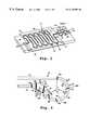
- FIG. 1is a perspective view of a microfabricated device constructed according to the present invention, having an open electrophoresis channel and liquid reservoirs formed on a substrate;
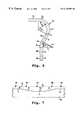
- FIG. 2is an enlarged view of a 180° bend in a serpentine channel formed in accordance with the present invention, illustrating the effect of the self-correcting bend on band distortion;
- FIGS. 3 A- 3 Care sectional views taken along lines 3 A- 3 A, 3 B- 3 B, and 3 C- 3 C, respectively, in FIG. 2;
- FIG. 4is an enlarged view of a 90° bend in a serpentine channel formed in accordance with one embodiment of the present invention
- FIG. 5is an enlarged view of a 90° bend in a serpentine channel formed in accordance with another embodiment of the invention.
- FIG. 6is an enlarged view of a 90° bend in a serpentine channel formed in accordance with yet another embodiment of the invention.
- FIG. 7is a cross-section of the channel region in FIG. 6, taken along the channel pathway 7 — 7 in FIG. 6 .
- FIG. 1shows a microfabricated device 10 constructed in accordance with the invention, for electrophoretic separation and/or characterization of one or more analytes in a sample mixture.
- the devicegenerally includes a planar substrate 12 having formed in its upper surface 14 , open reservoirs 16 , 18 , 19 , and 20 , and a serpentine electrophoresis channel 22 connecting the reservoirs.
- Reservoirs 18 and 16which are intended to contain electrophoresis buffer and sample fluid, respectively, are connected in fluid communication with each other and with channel 22 through a fork-like connector 24 .
- Reservoirs 19 , 20are intended to hold the waste reservoir.
- the four reservoirsare connected to electrodes 26 , 28 , 21 , and 30 , as shown, which are in turn connected to suitable voltage leads during operation of the device, for (i) loading sample from reservoir 16 into channel 22 , by applying a voltage across electrodes 26 , 28 , and (ii) (ii) electrophoretically separating charged sample components, by applying a voltage difference across opposite ends of the channel, i.e., across electrodes 21 , 30 .
- channel 22includes a plurality of parallel linear channel segments, such as segments 32 , 34 , and 36 , and curved channel regions connecting the adjacent ends of adjacent linear segments, such as curved channel region 38 connecting adjacent ends of segments 32 , 34 .
- the substrate or chiphas side dimensions of between about 1 to 15 cm, and the linear segments are each about 0.5 to 10 cm in length.
- a channel having 30 linear segments, each about 8 mm in lengthhas a column length, ignoring the lengths of the connecting regions, of about 250 mm. With the added lengths of the connecting regions, the total length may be in the 30 cm range, on a chip whose side dimensions may be as little as 1 cm.
- a coverslip 23 placed over the portion of the substrate having the serpentine channelserves to enclose the channel, although an open serpentine channel is also contemplated.
- region 38The construction of a curved connecting region—in this case, region 38 —is shown in enlarged plan view in FIG. 2, which shows portions of linear segments 32 , 34 connected by the region.
- the regionincludes a first curved channel portion 40 which subtends an angle ⁇ f which is greater than the minimum angle ⁇ needed to connect the two segments.
- ⁇ fis typically between about 200°-250°, i.e., about 20°-70° over the minimum angle.
- portion 40has a substantially constant channel width W f along its length, equal to the channel width of the connected linear segments.
- the channelhas a substantially rectangular cross-section with a width dimension W f and depth dimension d f .
- W fis typically between about 25-200, preferably 50-100 microns
- d fis typically about 5-100, preferably 25-75 microns.
- ⁇ s⁇ f ⁇ .
- the width W s of the second curved portionis greater than W f and is selected, in relation to the two angles ⁇ f and ⁇ s , and in accordance with the invention, to correct band distortion produced as a band moves through portion 40 , as will be described below.
- W sis greater than W f , acting in effect reduce the electric field strength on analyte molecules migrating through this portion, relative to portion 40 .
- Channel region 38further includes two tapered-width segments 44 , 46 , which serve as interfaces between (i) the smaller-width portion 40 and the larger-width portion 42 (segment 44 ) and between (ii) the larger-width portion 42 and the smaller-width linear segment 34 (segment 46 ).
- a cross-sectional view of segment 44is shown in FIG. 3B, showing a channel width intermediate between that of portions 40 , 42 , and the same channel depth.
- a charged species migrating as a band through the channelis indicated at various stages through the curved channel regions by numerals 48 a - 48 g .
- Band 48 awhich is at the position just entering the curved channel portion, is substantially undistorted, meaning that the band is both narrow and disposed along an axis substantially normal to the channel axis.
- As the band enters channel portion 40it begins to distort, as shown at 48 b , due to the shorter migration distance of molecules along the inner track 40 a and the longer migration distance of molecules along the outer track 40 b .
- the distortionincreases progressively as the band migrates through portion 40 , as illustrated by bands 48 c and 48 d.
- a band on the inside trackwill lead a band on the outside track with a time ⁇ t f approximately equal to ⁇ f (2W f R f )/ ⁇ E f-center , where R f is the radius of curvature of curved portion 40 , W f is the channel width, ⁇ is the mobility of the migrating species, in m 2 /Vsec, and E f-center is the electric field in portion 40 at the center of the track, resulting from the potential difference applied across opposite ends of the channel.
- the purpose of the second curved portionis to provide a correction, on the opposite channel side, for the band distortion produced in the first curved portion.
- this second curved portionis designed such that a band on the inside track 42 b (which is the shorter of the two tracks) will lead the band on the outside track 42 a by a time ⁇ t s substantially equal to ⁇ t f .
- W fis 50 ⁇ m
- ⁇ sis 210°
- ⁇ sis 30°
- W sis then ((50 ⁇ m) 2 ( 210/30)) 1 ⁇ 2 , or about 132 ⁇ m.
- band 48 dmigrates through tapered segment 44 substantially without correction, is fully corrected within portion 42 , and then migrates through segment 46 and into segment 34 in corrected form, i.e., with the band axis oriented substantially normal to the segment axis.
- FIG. 4shows an embodiment of a 90° curved channel region 50 constructed in accordance with the invention, for use, for example, in a serpentine channel of the type described above, but where each 180° turn is produced by two adjoining 90° turns.
- Channel region 50joins two linear channel segments 52 , 54 which in this embodiment are disposed at right angles with respect to one another.
- ⁇ fis typically between about 110° and 160°
- ⁇ sis between about 20° and 70°, respectively.
- the width W s of the second curved portionis greater than W f and is selected, in relation to the two angles ⁇ f and ⁇ s , and in accordance with the invention, to correct band distortion produced as a band moves through portion 56 , as will be described below.
- W fis 50 ⁇ m
- ⁇ sis 120° and ⁇ s is 30°
- W sis then (50 ⁇ m 2 (120/30)) 1 ⁇ 2 , or 100 ⁇ m.
- Region 50further includes tapered segments 60 , 62 which serve as interfaces between (i) the smaller-width portion 56 and the larger-width portion 58 , and (ii) the larger-width portion 58 and the smaller-width linear segment 54 .
- an analyte band migrating into portion 56substantially normal to the axis of segment 52 , will become distorted by its migration through portion 56 , with the outer-side of the band trailing the inner side of the band.
- the analytemigrates through tapered segment 60 substantially without correction, is fully corrected within portion 58 and then migrates through segment 62 and into segment 54 in corrected form, i.e., with the band axis oriented substantially normal to the segment axis.
- FIG. 5shows another embodiment of a 90° curved channel region 64 constructed in accordance with the invention, for use, for example, in a serpentine channel 66 of the type described above.
- Channel region 64joins two linear channel segments 68 , 70 which in this embodiment are disposed at right angles with respect to one another.
- Channel region 64includes a first curved channel portion 72 subtending an angle ⁇ f which is greater than 90°, and a second channel portion 74 subtending an angle ⁇ s which corrects the overangle ⁇ f to provided the desired 90° total angle in the curved portion.
- This embodimentdiffers from the one illustrated in FIG. 4 in that curved portion 74 replaces portion 58 and the two tapered segments 60 , 62 in portion 58 , as a continuously curved portion. That is, W s is continuously variable through portion 74 , from a minimum width W s to a maximum width W s-max .
- Exemplary angles ⁇ s , ⁇ fare as above, where the radius of curvature R s of portion 74 is about 3-4 times that in the FIG. 4 embodiment, but the angle ⁇ s subtending the portion is about the same in both embodiments.
- the relationship between W s and W fis more complex than that shown above, but can be determined from the relationships given above, by integrating over ⁇ s , where the value of W s varies continuously over portion 74 according to a known angle-dependent relationship.
- portion 74in correcting band distortion produced in portion 72 is substantially as described above, but where band correction occurs over the entire region between portion 72 and segment 70 .
- angle channel region 76is illustrated by angle channel region 76 in FIG. 6 .
- the channel regionwhich joins right-angle channel segments 78 , 80 , includes a first curved channel portion 82 subtending an angle ⁇ f >90°, and a second curved channel portion 84 subtending an angle ⁇ s , which corrects the overangle ⁇ f to provide the desired 90° total angle in the curved portion.
- interface segments 86 , 88connecting portion 82 to portion 84 , and portion 84 to segment 80 , respectively.
- Exemplary ⁇ f and ⁇ sare as above.
- the embodimentdiffers from those above in that the width W f of portion 84 is the same the width W s of portion 82 , but portion 84 has a depth d s which is greater than d f , as illustrated in FIG. 7, which shows a segmented cross-section (through segments indicated by A, B, C, D, and E) along indicated portions of region 76 . Also as seen, interface segments 86 , 88 have tapered channel depths, rather than the tapered channel widths of the interface segments in the earlier described embodiments.
- d sis then (50 ⁇ m) (120/30), or about 200 ⁇ m.
- region 76 in correcting band distortionis similar to that described above, for example, with respect to the embodiment shown in FIG. 4 .
- a bandbecomes distorted by its migration through portion 82 , with the outer-side of the band trailing the inner side of the band.
- the bandmigrates through tapered segment 86 substantially without correction, is fully corrected within portion 84 and then migrates through segment 88 and into segment 80 in corrected form, i.e., with the band axis oriented substantially normal to the segment axis.
- the inventionis compatible with tightly coiled serpentine electrophoresis or other chromatographic channel configurations formed in a small-area microchip, for example, using conventional microfabrication techniques.
- the microfabrication methodmay involve either same-depth, variable-width etching, or same-width, variable depth etching, or a combination of the two.
- the self-correcting bend feature of the inventionacts to correct distortion produced by band migration around a turn, due to slower migration at the outside of the turn, acting to preserve band resolution along the entire channel length, which may include numerous turns, typically 90° or 180° turns.
- the serpentine channelmay be formed by chemical or laser etching techniques on a relatively large-scale plate, e.g., a 10 cm ⁇ 10 cm plate designed for preparative electrophoresis or chromatography.
- the serpentine channelmay be formed in a closed tube, such as a capillary electrophoresis tube, where each turn in the tube includes an expanded diameter, self-correcting counter turn.
- the self-correcting turnmay apply to other types of chromatography channels or tubes, dependent on pressurized fluid flow or gravity rather than a voltage difference as a motive force for moving analyte molecules through a separation medium.
Landscapes
- Health & Medical Sciences (AREA)
- Life Sciences & Earth Sciences (AREA)
- Chemical & Material Sciences (AREA)
- Molecular Biology (AREA)
- Analytical Chemistry (AREA)
- Pathology (AREA)
- Electrochemistry (AREA)
- Physics & Mathematics (AREA)
- Chemical Kinetics & Catalysis (AREA)
- Biochemistry (AREA)
- General Health & Medical Sciences (AREA)
- General Physics & Mathematics (AREA)
- Immunology (AREA)
- Dispersion Chemistry (AREA)
- Automatic Analysis And Handling Materials Therefor (AREA)
- Investigating Or Analyzing Materials By The Use Of Electric Means (AREA)
- Investigating, Analyzing Materials By Fluorescence Or Luminescence (AREA)
- Devices For Indicating Variable Information By Combining Individual Elements (AREA)
- Micromachines (AREA)
Abstract
Description
Claims (30)
Priority Applications (1)
| Application Number | Priority Date | Filing Date | Title |
|---|---|---|---|
| US09/191,417US6176991B1 (en) | 1997-11-12 | 1998-11-12 | Serpentine channel with self-correcting bends |
Applications Claiming Priority (2)
| Application Number | Priority Date | Filing Date | Title |
|---|---|---|---|
| US6510097P | 1997-11-12 | 1997-11-12 | |
| US09/191,417US6176991B1 (en) | 1997-11-12 | 1998-11-12 | Serpentine channel with self-correcting bends |
Publications (1)
| Publication Number | Publication Date |
|---|---|
| US6176991B1true US6176991B1 (en) | 2001-01-23 |
Family
ID=22060347
Family Applications (1)
| Application Number | Title | Priority Date | Filing Date |
|---|---|---|---|
| US09/191,417Expired - Fee RelatedUS6176991B1 (en) | 1997-11-12 | 1998-11-12 | Serpentine channel with self-correcting bends |
Country Status (8)
| Country | Link |
|---|---|
| US (1) | US6176991B1 (en) |
| EP (1) | EP1031032B1 (en) |
| JP (1) | JP2001523001A (en) |
| AT (1) | ATE220456T1 (en) |
| AU (1) | AU747940B2 (en) |
| CA (1) | CA2307623C (en) |
| DE (1) | DE69806499T2 (en) |
| WO (1) | WO1999024828A1 (en) |
Cited By (47)
| Publication number | Priority date | Publication date | Assignee | Title |
|---|---|---|---|---|
| US20010035350A1 (en)* | 2000-03-28 | 2001-11-01 | Minoru Seki | Microchip for aqueous distribution and method of aqueous distribution using the same |
| WO2002037092A1 (en)* | 2000-11-06 | 2002-05-10 | Dna Sciences, Inc. | Microchannel turn design |
| US20020148640A1 (en)* | 2001-04-12 | 2002-10-17 | Holl Technologies Company | Methods of manufacture of electric circuit substrates and components having multiple electric characteristics and substrates and components so manufactured |
| US20030031090A1 (en)* | 2000-08-10 | 2003-02-13 | University Of California | Micro chaotic mixer |
| US20030043690A1 (en)* | 2001-03-07 | 2003-03-06 | Holl Technologies Company | Methods and apparatus for materials processing |
| US20030066624A1 (en)* | 2001-09-13 | 2003-04-10 | Holl Richard A. | Methods and apparatus for transfer of heat energy between a body surface and heat transfer fluid |
| US20030166265A1 (en)* | 2002-02-26 | 2003-09-04 | Pugia Michael J. | Method and apparatus for precise transfer and manipulation of fluids by centrifugal and/or capillary forces |
| US20030230489A1 (en)* | 2002-06-10 | 2003-12-18 | Cummings Eric B. | Piecewise uniform conduction-like flow channels and method therefor |
| US20040013587A1 (en)* | 2002-07-16 | 2004-01-22 | Holl Richard A. | Processes employing multiple successive chemical reaction process steps and apparatus therefore |
| US20040052158A1 (en)* | 2002-09-11 | 2004-03-18 | Holl Richard A. | Methods and apparatus for high-shear mixing and reacting of materials |
| US6712925B1 (en) | 1998-05-18 | 2004-03-30 | University Of Washington | Method of making a liquid analysis cartridge |
| US6733730B1 (en)* | 1999-04-26 | 2004-05-11 | Sandia Corporation | Method and apparatus for reducing sample dispersion in turns and junctions of microchannel systems |
| US6742774B2 (en) | 1999-07-02 | 2004-06-01 | Holl Technologies Company | Process for high shear gas-liquid reactions |
| US20040121449A1 (en)* | 2002-12-19 | 2004-06-24 | Pugia Michael J. | Method and apparatus for separation of particles in a microfluidic device |
| US6787246B2 (en) | 2001-10-05 | 2004-09-07 | Kreido Laboratories | Manufacture of flat surfaced composites comprising powdered fillers in a polymer matrix |
| US20040188077A1 (en)* | 2002-10-03 | 2004-09-30 | Holl Technologies Company | Apparatus for transfer of heat energy between a body surface and heat transfer fluid |
| US20040241042A1 (en)* | 2003-05-29 | 2004-12-02 | Pugia Michael J. | Packaging of microfluidic devices |
| US6830729B1 (en) | 1998-05-18 | 2004-12-14 | University Of Washington | Sample analysis instrument |
| US20040252584A1 (en)* | 2003-06-11 | 2004-12-16 | Agency For Science, Technology And Research | Micromixer apparatus and methods of using same |
| US20040265172A1 (en)* | 2003-06-27 | 2004-12-30 | Pugia Michael J. | Method and apparatus for entry and storage of specimens into a microfluidic device |
| US20040265171A1 (en)* | 2003-06-27 | 2004-12-30 | Pugia Michael J. | Method for uniform application of fluid into a reactive reagent area |
| US20050033069A1 (en)* | 1999-07-02 | 2005-02-10 | Holl Richard A. | Process for high shear gas-liquid reactions |
| US20050041525A1 (en)* | 2003-08-19 | 2005-02-24 | Pugia Michael J. | Mixing in microfluidic devices |
| US20050153433A1 (en)* | 2001-08-28 | 2005-07-14 | Gyros Ab | Retaining microfluidic microcavity and other microfluidic structures |
| US20050238506A1 (en)* | 2002-06-21 | 2005-10-27 | The Charles Stark Draper Laboratory, Inc. | Electromagnetically-actuated microfluidic flow regulators and related applications |
| US20060030837A1 (en)* | 2004-01-29 | 2006-02-09 | The Charles Stark Draper Laboratory, Inc. | Drug delivery apparatus |
| US7125711B2 (en) | 2002-12-19 | 2006-10-24 | Bayer Healthcare Llc | Method and apparatus for splitting of specimens into multiple channels of a microfluidic device |
| US20060243140A1 (en)* | 2003-01-27 | 2006-11-02 | Uwe Lehmann | Separating column, especially for a miniaturised gas chromatograph |
| US20060285433A1 (en)* | 2005-06-20 | 2006-12-21 | Jing-Tang Yang | Fluidic mixer of serpentine channel incorporated with staggered sudden-expansion and convergent cross sections |
| US20070246106A1 (en)* | 2006-04-25 | 2007-10-25 | Velocys Inc. | Flow Distribution Channels To Control Flow in Process Channels |
| US20080087546A1 (en)* | 2003-05-19 | 2008-04-17 | Protasis Corporation | Electrophoresis Devices And Methods For Focusing Charged Analytes |
| WO2008108191A1 (en)* | 2007-03-02 | 2008-09-12 | Canon Kabushiki Kaisha | Fluid transport channel, fluid processing apparatus and fluid processing system |
| US20080249510A1 (en)* | 2007-01-31 | 2008-10-09 | Mescher Mark J | Membrane-based fluid control in microfluidic devices |
| US20080257754A1 (en)* | 2003-06-27 | 2008-10-23 | Pugia Michael J | Method and apparatus for entry of specimens into a microfluidic device |
| US20090111192A1 (en)* | 2007-10-26 | 2009-04-30 | Seiko Epson Corporation | Biogenic substance detector and biogenic substance detection method |
| US20090268548A1 (en)* | 2005-08-11 | 2009-10-29 | Eksigent Technologies, Llc | Microfluidic systems, devices and methods for reducing diffusion and compliance effects at a fluid mixing region |
| US7867194B2 (en) | 2004-01-29 | 2011-01-11 | The Charles Stark Draper Laboratory, Inc. | Drug delivery apparatus |
| US20110024296A1 (en)* | 2003-09-05 | 2011-02-03 | Caliper Life Sciences, Inc. | Analyte Injection System |
| US20110223605A1 (en)* | 2009-06-04 | 2011-09-15 | Lockheed Martin Corporation | Multiple-sample microfluidic chip for DNA analysis |
| CN102788831A (en)* | 2012-08-13 | 2012-11-21 | 中国科学院研究生院 | Microfluidic chip electrophoretic-electrochemical detecting device with adjustable pH after separation and use thereof |
| US8430558B1 (en)* | 2008-09-05 | 2013-04-30 | University Of Central Florida Research Foundation, Inc. | Microfluidic mixer having channel width variation for enhanced fluid mixing |
| WO2013105966A1 (en)* | 2012-01-12 | 2013-07-18 | Senftleber Fred | Apparatus and methods for transferring materials between locations possessing different cross-sectional areas with minimal band spreading and dispersion due to unequal path-lengths |
| US20140065034A1 (en)* | 2012-08-31 | 2014-03-06 | Yun Zheng | Microfluidic device and method of fabricating microfluidic devices |
| US8876795B2 (en) | 2011-02-02 | 2014-11-04 | The Charles Stark Draper Laboratory, Inc. | Drug delivery apparatus |
| US8961764B2 (en) | 2010-10-15 | 2015-02-24 | Lockheed Martin Corporation | Micro fluidic optic design |
| US9322054B2 (en) | 2012-02-22 | 2016-04-26 | Lockheed Martin Corporation | Microfluidic cartridge |
| WO2022241247A1 (en)* | 2021-05-13 | 2022-11-17 | Fluid-Screen, Inc. | Microfluidic device with improved flow profile |
Families Citing this family (11)
| Publication number | Priority date | Publication date | Assignee | Title |
|---|---|---|---|---|
| US6913679B1 (en)* | 1999-02-11 | 2005-07-05 | The Regents Of The University Of California | Apparatus and methods for high resolution separation of sample components on microfabricated channel devices |
| US6596140B2 (en) | 2001-05-01 | 2003-07-22 | Applera Corporation | Multi-channel capillary electrophoresis device and method |
| KR100442680B1 (en)* | 2001-05-10 | 2004-08-02 | 주식회사 디지탈바이오테크놀러지 | Apparatus for mixing fluids by micro channel |
| KR100442681B1 (en)* | 2001-05-10 | 2004-08-02 | 주식회사 디지탈바이오테크놀러지 | Channel unit and apparatus for mixing fluids using the unit |
| KR100473364B1 (en)* | 2001-10-17 | 2005-03-08 | 주식회사 디지탈바이오테크놀러지 | Microchannel apparatus for mixing liquids using microchannel and method therefor |
| JP2005024316A (en)* | 2003-06-30 | 2005-01-27 | Kyocera Corp | Microchemical chip and manufacturing method thereof |
| CN101765762B (en)* | 2007-04-16 | 2013-08-14 | 通用医疗公司以马萨诸塞州通用医疗公司名义经营 | Systems and methods for aggregating particles in microchannels |
| US8377277B2 (en) | 2008-10-22 | 2013-02-19 | General Electric Company | System and method for performing microfluidic manipulation |
| JP5008690B2 (en)* | 2009-03-31 | 2012-08-22 | 信和化工株式会社 | Microchannel device and method for manufacturing microchannel device |
| CA2810805C (en)* | 2010-09-26 | 2014-11-18 | Da Yu Enterprises, Llc | Separation of analytes |
| CN106596692B (en)* | 2017-01-14 | 2018-12-28 | 常州大学 | A kind of method of tortuous capillary electrophoresis detection antibody polypeptides interaction |
Citations (6)
| Publication number | Priority date | Publication date | Assignee | Title |
|---|---|---|---|---|
| WO1991016966A1 (en) | 1990-05-10 | 1991-11-14 | Pharmacia Biosensor Ab | Microfluidic structure and process for its manufacture |
| WO1996004547A1 (en) | 1994-08-01 | 1996-02-15 | Lockheed Martin Energy Systems, Inc. | Apparatus and method for performing microfluidic manipulations for chemical analysis and synthesis |
| US5599432A (en) | 1993-11-11 | 1997-02-04 | Ciba-Geigy Corporation | Device and a method for the electrophoretic separation of fluid substance mixtures |
| US5958694A (en)* | 1997-10-16 | 1999-09-28 | Caliper Technologies Corp. | Apparatus and methods for sequencing nucleic acids in microfluidic systems |
| US5993750A (en)* | 1997-04-11 | 1999-11-30 | Eastman Kodak Company | Integrated ceramic micro-chemical plant |
| US6033628A (en)* | 1994-10-19 | 2000-03-07 | Agilent Technologies, Inc. | Miniaturized planar columns for use in a liquid phase separation apparatus |
Family Cites Families (4)
| Publication number | Priority date | Publication date | Assignee | Title |
|---|---|---|---|---|
| EP0339780B1 (en)* | 1988-04-29 | 1996-08-28 | Beckman Instruments, Inc. | Capillary detector cartridge for electrophoresis |
| JPH03223674A (en)* | 1989-11-30 | 1991-10-02 | Mochida Pharmaceut Co Ltd | Reaction vessel |
| WO1993022053A1 (en)* | 1992-05-01 | 1993-11-11 | Trustees Of The University Of Pennsylvania | Microfabricated detection structures |
| JP3839524B2 (en)* | 1995-06-07 | 2006-11-01 | アジレント・テクノロジーズ・インク | Miniaturized total analysis system |
- 1998
- 1998-11-12WOPCT/US1998/024202patent/WO1999024828A1/enactiveIP Right Grant
- 1998-11-12EPEP98958561Apatent/EP1031032B1/ennot_activeExpired - Lifetime
- 1998-11-12ATAT98958561Tpatent/ATE220456T1/ennot_activeIP Right Cessation
- 1998-11-12JPJP2000519780Apatent/JP2001523001A/enactivePending
- 1998-11-12AUAU14580/99Apatent/AU747940B2/ennot_activeCeased
- 1998-11-12DEDE69806499Tpatent/DE69806499T2/ennot_activeExpired - Lifetime
- 1998-11-12CACA002307623Apatent/CA2307623C/ennot_activeExpired - Fee Related
- 1998-11-12USUS09/191,417patent/US6176991B1/ennot_activeExpired - Fee Related
Patent Citations (7)
| Publication number | Priority date | Publication date | Assignee | Title |
|---|---|---|---|---|
| WO1991016966A1 (en) | 1990-05-10 | 1991-11-14 | Pharmacia Biosensor Ab | Microfluidic structure and process for its manufacture |
| US5599432A (en) | 1993-11-11 | 1997-02-04 | Ciba-Geigy Corporation | Device and a method for the electrophoretic separation of fluid substance mixtures |
| WO1996004547A1 (en) | 1994-08-01 | 1996-02-15 | Lockheed Martin Energy Systems, Inc. | Apparatus and method for performing microfluidic manipulations for chemical analysis and synthesis |
| US6033546A (en)* | 1994-08-01 | 2000-03-07 | Lockheed Martin Energy Research Corporation | Apparatus and method for performing microfluidic manipulations for chemical analysis and synthesis |
| US6033628A (en)* | 1994-10-19 | 2000-03-07 | Agilent Technologies, Inc. | Miniaturized planar columns for use in a liquid phase separation apparatus |
| US5993750A (en)* | 1997-04-11 | 1999-11-30 | Eastman Kodak Company | Integrated ceramic micro-chemical plant |
| US5958694A (en)* | 1997-10-16 | 1999-09-28 | Caliper Technologies Corp. | Apparatus and methods for sequencing nucleic acids in microfluidic systems |
Non-Patent Citations (3)
| Title |
|---|
| Jacobson, S.C., and Ramsey J.M., "Microchip electrophoresis with sample stacking," Electrophoresis 16:481-486 (1995). |
| Jacobson, S.C., et al., "Effects of Injection Schemes and Column Geometry on the Performance of Microchip Electrophoresis Devices" Anal. Chem. (1994) 66:1107-1113. |
| Jacobson, S.C., et al., "Open Channel Electrochromatography on a Microchip," Anal. Chem. 66:2369-2373 (1994). |
Cited By (90)
| Publication number | Priority date | Publication date | Assignee | Title |
|---|---|---|---|---|
| US6712925B1 (en) | 1998-05-18 | 2004-03-30 | University Of Washington | Method of making a liquid analysis cartridge |
| US20060127275A1 (en)* | 1998-05-18 | 2006-06-15 | University Of Washington | Liquid analysis cartridge |
| US6830729B1 (en) | 1998-05-18 | 2004-12-14 | University Of Washington | Sample analysis instrument |
| US6852284B1 (en) | 1998-05-18 | 2005-02-08 | University Of Washington | Liquid analysis cartridge |
| US7226562B2 (en) | 1998-05-18 | 2007-06-05 | University Of Washington | Liquid analysis cartridge |
| US6733730B1 (en)* | 1999-04-26 | 2004-05-11 | Sandia Corporation | Method and apparatus for reducing sample dispersion in turns and junctions of microchannel systems |
| US7538237B2 (en) | 1999-07-02 | 2009-05-26 | Kreido Laboratories | Process for high shear gas-liquid reactions |
| US6994330B2 (en) | 1999-07-02 | 2006-02-07 | Kriedo Laboratories | Process for high shear gas-liquid reactions |
| US6742774B2 (en) | 1999-07-02 | 2004-06-01 | Holl Technologies Company | Process for high shear gas-liquid reactions |
| US20050033069A1 (en)* | 1999-07-02 | 2005-02-10 | Holl Richard A. | Process for high shear gas-liquid reactions |
| US20040222536A1 (en)* | 1999-07-02 | 2004-11-11 | Holl Richard A. | Process for high shear gas-liquid reactions |
| US20010035350A1 (en)* | 2000-03-28 | 2001-11-01 | Minoru Seki | Microchip for aqueous distribution and method of aqueous distribution using the same |
| US6902313B2 (en)* | 2000-08-10 | 2005-06-07 | University Of California | Micro chaotic mixer |
| US20030031090A1 (en)* | 2000-08-10 | 2003-02-13 | University Of California | Micro chaotic mixer |
| US20020060153A1 (en)* | 2000-11-06 | 2002-05-23 | Dna Sciences, Inc. | Microchannel turn design |
| WO2002037092A1 (en)* | 2000-11-06 | 2002-05-10 | Dna Sciences, Inc. | Microchannel turn design |
| US20030043690A1 (en)* | 2001-03-07 | 2003-03-06 | Holl Technologies Company | Methods and apparatus for materials processing |
| US6752529B2 (en)* | 2001-03-07 | 2004-06-22 | Holl Technologies Company | Methods and apparatus for materials processing |
| US6830806B2 (en) | 2001-04-12 | 2004-12-14 | Kreido Laboratories | Methods of manufacture of electric circuit substrates and components having multiple electric characteristics and substrates and components so manufactured |
| US20020148640A1 (en)* | 2001-04-12 | 2002-10-17 | Holl Technologies Company | Methods of manufacture of electric circuit substrates and components having multiple electric characteristics and substrates and components so manufactured |
| US8268262B2 (en)* | 2001-08-28 | 2012-09-18 | Gyros Patent Ab | Retaining microfluidic microcavity and other microfluidic structures |
| US20050153433A1 (en)* | 2001-08-28 | 2005-07-14 | Gyros Ab | Retaining microfluidic microcavity and other microfluidic structures |
| US20030066624A1 (en)* | 2001-09-13 | 2003-04-10 | Holl Richard A. | Methods and apparatus for transfer of heat energy between a body surface and heat transfer fluid |
| US6787246B2 (en) | 2001-10-05 | 2004-09-07 | Kreido Laboratories | Manufacture of flat surfaced composites comprising powdered fillers in a polymer matrix |
| US8337775B2 (en) | 2002-02-26 | 2012-12-25 | Siemens Healthcare Diagnostics, Inc. | Apparatus for precise transfer and manipulation of fluids by centrifugal and or capillary forces |
| US20090004059A1 (en)* | 2002-02-26 | 2009-01-01 | Siemens Healthcare Diagnostics Inc. | Method and apparatus for precise transfer and manipulation of fluids by centrifugal and or capillary forces |
| US7459127B2 (en) | 2002-02-26 | 2008-12-02 | Siemens Healthcare Diagnostics Inc. | Method and apparatus for precise transfer and manipulation of fluids by centrifugal and/or capillary forces |
| US20030166265A1 (en)* | 2002-02-26 | 2003-09-04 | Pugia Michael J. | Method and apparatus for precise transfer and manipulation of fluids by centrifugal and/or capillary forces |
| US20030230489A1 (en)* | 2002-06-10 | 2003-12-18 | Cummings Eric B. | Piecewise uniform conduction-like flow channels and method therefor |
| US7005301B2 (en)* | 2002-06-10 | 2006-02-28 | Sandia National Laboratories | Piecewise uniform conduction-like flow channels and method therefor |
| US20050238506A1 (en)* | 2002-06-21 | 2005-10-27 | The Charles Stark Draper Laboratory, Inc. | Electromagnetically-actuated microfluidic flow regulators and related applications |
| US7575728B2 (en) | 2002-07-16 | 2009-08-18 | Kreido Laboratories | Processes employing multiple successive chemical reaction process steps and apparatus therefore |
| US7098360B2 (en) | 2002-07-16 | 2006-08-29 | Kreido Laboratories | Processes employing multiple successive chemical reaction process steps and apparatus therefore |
| US20060245991A1 (en)* | 2002-07-16 | 2006-11-02 | Kreido Laboratories | Processes Employing Multiple Successive Chemical Reaction Process Steps and Apparatus Therefore |
| US20040013587A1 (en)* | 2002-07-16 | 2004-01-22 | Holl Richard A. | Processes employing multiple successive chemical reaction process steps and apparatus therefore |
| US20040052158A1 (en)* | 2002-09-11 | 2004-03-18 | Holl Richard A. | Methods and apparatus for high-shear mixing and reacting of materials |
| US7165881B2 (en) | 2002-09-11 | 2007-01-23 | Holl Technologies Corporation | Methods and apparatus for high-shear mixing and reacting of materials |
| US6938687B2 (en) | 2002-10-03 | 2005-09-06 | Holl Technologies Company | Apparatus for transfer of heat energy between a body surface and heat transfer fluid |
| US20040188077A1 (en)* | 2002-10-03 | 2004-09-30 | Holl Technologies Company | Apparatus for transfer of heat energy between a body surface and heat transfer fluid |
| US7094354B2 (en) | 2002-12-19 | 2006-08-22 | Bayer Healthcare Llc | Method and apparatus for separation of particles in a microfluidic device |
| US7125711B2 (en) | 2002-12-19 | 2006-10-24 | Bayer Healthcare Llc | Method and apparatus for splitting of specimens into multiple channels of a microfluidic device |
| US20040121449A1 (en)* | 2002-12-19 | 2004-06-24 | Pugia Michael J. | Method and apparatus for separation of particles in a microfluidic device |
| US20060243140A1 (en)* | 2003-01-27 | 2006-11-02 | Uwe Lehmann | Separating column, especially for a miniaturised gas chromatograph |
| US8142630B2 (en)* | 2003-05-19 | 2012-03-27 | Protasis Corporation | Electrophoresis devices and methods for focusing charged analytes |
| US20080087546A1 (en)* | 2003-05-19 | 2008-04-17 | Protasis Corporation | Electrophoresis Devices And Methods For Focusing Charged Analytes |
| US20040241042A1 (en)* | 2003-05-29 | 2004-12-02 | Pugia Michael J. | Packaging of microfluidic devices |
| US7435381B2 (en) | 2003-05-29 | 2008-10-14 | Siemens Healthcare Diagnostics Inc. | Packaging of microfluidic devices |
| US20060087918A1 (en)* | 2003-06-11 | 2006-04-27 | Agency For Science, Technology And Research | Micromixer apparatus and methods of using same |
| US20040252584A1 (en)* | 2003-06-11 | 2004-12-16 | Agency For Science, Technology And Research | Micromixer apparatus and methods of using same |
| US7160025B2 (en)* | 2003-06-11 | 2007-01-09 | Agency For Science, Technology And Research | Micromixer apparatus and methods of using same |
| US20040265171A1 (en)* | 2003-06-27 | 2004-12-30 | Pugia Michael J. | Method for uniform application of fluid into a reactive reagent area |
| US20040265172A1 (en)* | 2003-06-27 | 2004-12-30 | Pugia Michael J. | Method and apparatus for entry and storage of specimens into a microfluidic device |
| US20080257754A1 (en)* | 2003-06-27 | 2008-10-23 | Pugia Michael J | Method and apparatus for entry of specimens into a microfluidic device |
| US7347617B2 (en)* | 2003-08-19 | 2008-03-25 | Siemens Healthcare Diagnostics Inc. | Mixing in microfluidic devices |
| US20050041525A1 (en)* | 2003-08-19 | 2005-02-24 | Pugia Michael J. | Mixing in microfluidic devices |
| US9539574B2 (en)* | 2003-09-05 | 2017-01-10 | Caliper Life Sciences, Inc. | Analyte injection system |
| US20110024296A1 (en)* | 2003-09-05 | 2011-02-03 | Caliper Life Sciences, Inc. | Analyte Injection System |
| US20060030837A1 (en)* | 2004-01-29 | 2006-02-09 | The Charles Stark Draper Laboratory, Inc. | Drug delivery apparatus |
| US9180054B2 (en) | 2004-01-29 | 2015-11-10 | The Charles Stark Draper Laboratory, Inc. | Drug delivery apparatus |
| US7867193B2 (en) | 2004-01-29 | 2011-01-11 | The Charles Stark Draper Laboratory, Inc. | Drug delivery apparatus |
| US7867194B2 (en) | 2004-01-29 | 2011-01-11 | The Charles Stark Draper Laboratory, Inc. | Drug delivery apparatus |
| US20060285433A1 (en)* | 2005-06-20 | 2006-12-21 | Jing-Tang Yang | Fluidic mixer of serpentine channel incorporated with staggered sudden-expansion and convergent cross sections |
| US20090268548A1 (en)* | 2005-08-11 | 2009-10-29 | Eksigent Technologies, Llc | Microfluidic systems, devices and methods for reducing diffusion and compliance effects at a fluid mixing region |
| US9752831B2 (en) | 2006-04-25 | 2017-09-05 | Velocys, Inc. | Flow distribution channels to control flow in process channels |
| US20070246106A1 (en)* | 2006-04-25 | 2007-10-25 | Velocys Inc. | Flow Distribution Channels To Control Flow in Process Channels |
| US9046192B2 (en) | 2007-01-31 | 2015-06-02 | The Charles Stark Draper Laboratory, Inc. | Membrane-based fluid control in microfluidic devices |
| US9651166B2 (en) | 2007-01-31 | 2017-05-16 | The Charles Stark Draper Laboratory, Inc. | Membrane-based fluid control in microfluidic devices |
| US20080249510A1 (en)* | 2007-01-31 | 2008-10-09 | Mescher Mark J | Membrane-based fluid control in microfluidic devices |
| US20100051128A1 (en)* | 2007-03-02 | 2010-03-04 | Canon Kabushiki Kaisha | Fluid transport channel, fluid processing apparatus and fluid processing system |
| WO2008108191A1 (en)* | 2007-03-02 | 2008-09-12 | Canon Kabushiki Kaisha | Fluid transport channel, fluid processing apparatus and fluid processing system |
| US7883901B2 (en)* | 2007-10-26 | 2011-02-08 | Seiko Epson Corporation | Biogenic substance detector and biogenic substance detection method |
| US20090111192A1 (en)* | 2007-10-26 | 2009-04-30 | Seiko Epson Corporation | Biogenic substance detector and biogenic substance detection method |
| US8430558B1 (en)* | 2008-09-05 | 2013-04-30 | University Of Central Florida Research Foundation, Inc. | Microfluidic mixer having channel width variation for enhanced fluid mixing |
| US20130223182A1 (en)* | 2008-09-05 | 2013-08-29 | University Of Central Florida Research Foundation, Inc. | Microfluidic mixing using channel width variation for enhanced fluid mixing |
| US9259693B2 (en)* | 2008-09-05 | 2016-02-16 | University Of Central Florida Research Foundation, Inc. | Microfluidic mixing using channel width variation for enhanced fluid mixing |
| US9067207B2 (en) | 2009-06-04 | 2015-06-30 | University Of Virginia Patent Foundation | Optical approach for microfluidic DNA electrophoresis detection |
| US9649631B2 (en) | 2009-06-04 | 2017-05-16 | Leidos Innovations Technology, Inc. | Multiple-sample microfluidic chip for DNA analysis |
| US20110229897A1 (en)* | 2009-06-04 | 2011-09-22 | Lockheed Martin Corporation | Optical approach for microfluidic DNA electrophoresis detection |
| US20110223605A1 (en)* | 2009-06-04 | 2011-09-15 | Lockheed Martin Corporation | Multiple-sample microfluidic chip for DNA analysis |
| US9656261B2 (en) | 2009-06-04 | 2017-05-23 | Leidos Innovations Technology, Inc. | DNA analyzer |
| US8961764B2 (en) | 2010-10-15 | 2015-02-24 | Lockheed Martin Corporation | Micro fluidic optic design |
| US8876795B2 (en) | 2011-02-02 | 2014-11-04 | The Charles Stark Draper Laboratory, Inc. | Drug delivery apparatus |
| US9764121B2 (en) | 2011-02-02 | 2017-09-19 | The Charles Stark Draper Laboratory, Inc. | Drug delivery apparatus |
| WO2013105966A1 (en)* | 2012-01-12 | 2013-07-18 | Senftleber Fred | Apparatus and methods for transferring materials between locations possessing different cross-sectional areas with minimal band spreading and dispersion due to unequal path-lengths |
| US9322054B2 (en) | 2012-02-22 | 2016-04-26 | Lockheed Martin Corporation | Microfluidic cartridge |
| US9988676B2 (en) | 2012-02-22 | 2018-06-05 | Leidos Innovations Technology, Inc. | Microfluidic cartridge |
| CN102788831A (en)* | 2012-08-13 | 2012-11-21 | 中国科学院研究生院 | Microfluidic chip electrophoretic-electrochemical detecting device with adjustable pH after separation and use thereof |
| CN102788831B (en)* | 2012-08-13 | 2014-07-30 | 中国科学院研究生院 | Microfluidic chip electrophoretic-electrochemical detecting device with adjustable pH after separation and use thereof |
| US20140065034A1 (en)* | 2012-08-31 | 2014-03-06 | Yun Zheng | Microfluidic device and method of fabricating microfluidic devices |
| WO2022241247A1 (en)* | 2021-05-13 | 2022-11-17 | Fluid-Screen, Inc. | Microfluidic device with improved flow profile |
Also Published As
| Publication number | Publication date |
|---|---|
| EP1031032B1 (en) | 2002-07-10 |
| ATE220456T1 (en) | 2002-07-15 |
| CA2307623A1 (en) | 1999-05-20 |
| EP1031032A1 (en) | 2000-08-30 |
| JP2001523001A (en) | 2001-11-20 |
| CA2307623C (en) | 2004-03-16 |
| AU1458099A (en) | 1999-05-31 |
| DE69806499T2 (en) | 2003-02-27 |
| AU747940B2 (en) | 2002-05-30 |
| DE69806499D1 (en) | 2002-08-14 |
| WO1999024828A1 (en) | 1999-05-20 |
Similar Documents
| Publication | Publication Date | Title |
|---|---|---|
| US6176991B1 (en) | Serpentine channel with self-correcting bends | |
| US6344145B1 (en) | Device to improve detection in electro-chromatography | |
| US6695009B2 (en) | Microfluidic methods, devices and systems for in situ material concentration | |
| US7285421B2 (en) | Apparatus for capillary electrophoresis and associated method | |
| US6270641B1 (en) | Method and apparatus for reducing sample dispersion in turns and junctions of microchannel systems | |
| Riekkola et al. | Terminology for analytical capillary electromigration techniques (IUPAC Recommendations 2003) | |
| US6627076B2 (en) | Compact microchannel system | |
| US8241476B1 (en) | Sol-gel coatings for on-line preconcentration in capillary electrophoresis | |
| JP5342031B2 (en) | Apparatus and method for high resolution separation of sample components on microfabricated channel devices | |
| WO2007002141A2 (en) | Apparatus and method for coupling microfluidic systems with electrospray ionization mass spectrometry utilizing a hydrodynamic flow restrictor | |
| AU2001280951A1 (en) | High throughput separations based analysis systems | |
| JPH02245655A (en) | Electrophoresis system | |
| US20040047767A1 (en) | Microfluidic channel for band broadening compensation | |
| US20030057092A1 (en) | Microfluidic methods, devices and systems for in situ material concentration | |
| Nashabeh et al. | Coupled fused silica capillaries for rapid capillary zone electrophoresis of proteins | |
| Law et al. | On‐line sample enrichment for the determination of proteins by capillary zone electrophoresis with poly (vinyl alcohol)‐coated bubble cell capillaries | |
| Gustafsson et al. | An electrochromatography chip with integrated waveguides for UV absorbance detection | |
| Shimura et al. | Isoelectric focusing in a microfluidically defined electrophoresis channel | |
| WO2001071331A1 (en) | Electrophoresis microchip and system | |
| US20050011761A1 (en) | Microfluidic methods, devices and systems for in situ material concentration | |
| US20090127114A1 (en) | Multi-channel capillary electrophoresis microchips and uses thereof | |
| JPH0943223A (en) | Capillary column | |
| US20020060153A1 (en) | Microchannel turn design | |
| Culbertson et al. | Minimizing Dispersion Introduced by Turns on Microchips | |
| Zhuang | Electrokinetic separations on microfluidic devices for N-glycan profiling |
Legal Events
| Date | Code | Title | Description |
|---|---|---|---|
| AS | Assignment | Owner name:PERKIN-ELMER CORPORATION/APPLIED BIOSYSTEMS DIVISI Free format text:ASSIGNMENT OF ASSIGNORS INTEREST;ASSIGNOR:NORDMAN, ERIC S.;REEL/FRAME:009741/0147 Effective date:19990113 | |
| AS | Assignment | Owner name:PE CORPORATION (NY), CALIFORNIA Free format text:CHANGE OF NAME;ASSIGNOR:PERKIN-ELMER CORPORATION, THE;REEL/FRAME:012676/0767 Effective date:20000522 | |
| AS | Assignment | Owner name:APPLERA CORPORATION, CALIFORNIA Free format text:ASSIGNMENT OF ASSIGNORS INTEREST;ASSIGNOR:PE CORPORATION (NY);REEL/FRAME:013563/0534 Effective date:20020628 | |
| FPAY | Fee payment | Year of fee payment:4 | |
| FPAY | Fee payment | Year of fee payment:8 | |
| AS | Assignment | Owner name:BANK OF AMERICA, N.A, AS COLLATERAL AGENT, WASHING Free format text:SECURITY AGREEMENT;ASSIGNOR:APPLIED BIOSYSTEMS, LLC;REEL/FRAME:021976/0001 Effective date:20081121 Owner name:BANK OF AMERICA, N.A, AS COLLATERAL AGENT,WASHINGT Free format text:SECURITY AGREEMENT;ASSIGNOR:APPLIED BIOSYSTEMS, LLC;REEL/FRAME:021976/0001 Effective date:20081121 | |
| AS | Assignment | Owner name:APPLIED BIOSYSTEMS INC.,CALIFORNIA Free format text:CHANGE OF NAME;ASSIGNOR:APPLERA CORPORATION;REEL/FRAME:023994/0538 Effective date:20080701 Owner name:APPLIED BIOSYSTEMS, LLC,CALIFORNIA Free format text:MERGER;ASSIGNOR:APPLIED BIOSYSTEMS INC.;REEL/FRAME:023994/0587 Effective date:20081121 Owner name:APPLIED BIOSYSTEMS INC., CALIFORNIA Free format text:CHANGE OF NAME;ASSIGNOR:APPLERA CORPORATION;REEL/FRAME:023994/0538 Effective date:20080701 Owner name:APPLIED BIOSYSTEMS, LLC, CALIFORNIA Free format text:MERGER;ASSIGNOR:APPLIED BIOSYSTEMS INC.;REEL/FRAME:023994/0587 Effective date:20081121 | |
| REMI | Maintenance fee reminder mailed | ||
| LAPS | Lapse for failure to pay maintenance fees | ||
| STCH | Information on status: patent discontinuation | Free format text:PATENT EXPIRED DUE TO NONPAYMENT OF MAINTENANCE FEES UNDER 37 CFR 1.362 | |
| FP | Lapsed due to failure to pay maintenance fee | Effective date:20130123 | |
| AS | Assignment | Owner name:APPLIED BIOSYSTEMS, INC., CALIFORNIA Free format text:LIEN RELEASE;ASSIGNOR:BANK OF AMERICA, N.A.;REEL/FRAME:030182/0677 Effective date:20100528 | |
| AS | Assignment | Owner name:APPLIED BIOSYSTEMS, LLC, CALIFORNIA Free format text:CORRECTIVE ASSIGNMENT TO CORRECT THE RECEIVING PARTY NAME PREVIOUSLY RECORDED AT REEL: 030182 FRAME: 0684. ASSIGNOR(S) HEREBY CONFIRMS THE SECURITY INTEREST;ASSIGNOR:BANK OF AMERICA, N.A.;REEL/FRAME:037997/0551 Effective date:20100528 Owner name:APPLIED BIOSYSTEMS, LLC, CALIFORNIA Free format text:CORRECTIVE ASSIGNMENT TO CORRECT THE RECEIVING PARTY NAME PREVIOUSLY RECORDED AT REEL: 030182 FRAME: 0677. ASSIGNOR(S) HEREBY CONFIRMS THE SECURITY INTEREST;ASSIGNOR:BANK OF AMERICA, N.A.;REEL/FRAME:037997/0551 Effective date:20100528 |