US6176903B1 - Device for removing gases from fluids - Google Patents
Device for removing gases from fluidsDownload PDFInfo
- Publication number
- US6176903B1 US6176903B1US08/861,543US86154397AUS6176903B1US 6176903 B1US6176903 B1US 6176903B1US 86154397 AUS86154397 AUS 86154397AUS 6176903 B1US6176903 B1US 6176903B1
- Authority
- US
- United States
- Prior art keywords
- chamber
- container
- fluid
- orifice
- partition wall
- Prior art date
- Legal status (The legal status is an assumption and is not a legal conclusion. Google has not performed a legal analysis and makes no representation as to the accuracy of the status listed.)
- Expired - Fee Related
Links
Images

Classifications
- A—HUMAN NECESSITIES
- A61—MEDICAL OR VETERINARY SCIENCE; HYGIENE
- A61M—DEVICES FOR INTRODUCING MEDIA INTO, OR ONTO, THE BODY; DEVICES FOR TRANSDUCING BODY MEDIA OR FOR TAKING MEDIA FROM THE BODY; DEVICES FOR PRODUCING OR ENDING SLEEP OR STUPOR
- A61M1/00—Suction or pumping devices for medical purposes; Devices for carrying-off, for treatment of, or for carrying-over, body-liquids; Drainage systems
- A61M1/14—Dialysis systems; Artificial kidneys; Blood oxygenators ; Reciprocating systems for treatment of body fluids, e.g. single needle systems for hemofiltration or pheresis
- A61M1/16—Dialysis systems; Artificial kidneys; Blood oxygenators ; Reciprocating systems for treatment of body fluids, e.g. single needle systems for hemofiltration or pheresis with membranes
- A61M1/1654—Dialysates therefor
- A61M1/1656—Apparatus for preparing dialysates
- A61M1/1658—Degasification
- A—HUMAN NECESSITIES
- A61—MEDICAL OR VETERINARY SCIENCE; HYGIENE
- A61M—DEVICES FOR INTRODUCING MEDIA INTO, OR ONTO, THE BODY; DEVICES FOR TRANSDUCING BODY MEDIA OR FOR TAKING MEDIA FROM THE BODY; DEVICES FOR PRODUCING OR ENDING SLEEP OR STUPOR
- A61M2205/00—General characteristics of the apparatus
- A61M2205/75—General characteristics of the apparatus with filters
- A61M2205/7536—General characteristics of the apparatus with filters allowing gas passage, but preventing liquid passage, e.g. liquophobic, hydrophobic, water-repellent membranes
Definitions
- the inventionrelates to a device for removing gases from fluids, in particular from a dialyzing fluid.
- a plurality of devices for separating out airare known, such as bubble traps or air-venting devices, whose task is to effectively separate out the gases, which are present and partly dissolved in the fluid from the fluid.
- the dialyzing fluids used in dialysis release gases in response to low pressure air separatorswhich usually include a laterally disposed upper inlet, whose intended use is to impress a helical path upon the inflowing fluid.
- the air bubblesare to be separated out through a hydrophobic filter situated at the top.
- An arrangement of this kindis disclosed, for example, by the German Patent No. 32 15 003.
- separation aids in the form of small plateswere introduced into the venting space.
- the air separatorswere often built with very long dimensions to form the largest possible separation surface.
- a deviceis disclosed in U.S. Pat. No. 4,061,031 that can be used both as a flow meter as well as an air separator.
- the known devicehas a container, which is divided by a partition wall that includes two chambers, one chamber being provided with an inlet orifice, and the other chamber with an outlet orifice.
- the partition wallincludes an opening, and extends from the bottom of the container up to near the container cover, forming a gap-shaped interstitial space between the inlet chamber and the outlet chamber as well as the container cover.
- the cut-through partition wallis comprised of two plate-shaped elements in a staggered arrangement, the orifices of the inlet and outlet chambers being situated at the bottom of the container. Since the opening in the partition wall has a smaller cross-section than the inlet orifice, fluid columns of different heights form in the chambers, making it possible to measure the flow rate. In this context, the difference between the two fluid columns is a measure of the level of the flow rate.
- the two chambersfunction as bubble traps.
- the air bubbles entrapped in the fluidrise to the top of the chambers and remain as gas above the fluid level. An active separation is no longer possible when working with the known device.
- the inlet chamberhas an elongated shape, which leads to a relatively substantial overall height.
- the partition wallis formed as a continuous traversing body, so that the first orifice and the second orifice are in fluid communication only via a gap-shaped interstitial space. Furthermore, provision is made on the container cover for a venting orifice that is sealed by a vent unit, which permits gas to pass through, but not fluid.
- the containeri.e., the two chambers and the gap-shaped interstitial space, are completely filled with fluid. The is fluid to be degassed flows out of the one chamber, across the gap-shaped interstitial space beneath the container cover, into the other chamber.
- a reversal of the flow directiontakes place, the gases entrapped in the fluid are able to escape through the venting orifice provided on the container cover.
- An especially high separation rateis achieved with a device of a compact design, particularly when the partition wall is conceived in the form of a hollow body, which, while forming the first and second chamber, is so arranged inside the container that the inner first chamber has a smaller cross-section than the outer second chamber.
- the first chamberforms the inlet chamber and the second chamber the outlet chamber. Since the inlet chamber has a smaller cross-section than the outlet chamber, the flow rate in the first chamber and, thus, the static pressure acting on the venting orifice is increased. On the other hand, the dynamic pressure at the venting orifice is kept low, so that in spite of the increased flow rate in the first chamber, virtually no air is entrained.
- the vent unitcan be designed, for example, as a hydrophobic membrane.
- This membraneis advantageously integrated in the container cover, so that the fluid to be degassed is pressed against the membrane.
- the hydrophobic membraneshould form the largest possible working surface for the fluid and preferably extend nearly over the entire cross-sectional surface of the gap-shaped interstitial space.
- the inflowing fluidis essentially carried upwards in a spiral shape, thereby improving the air separation.
- the inflowing fluid mixtureis set into a rotational motion within the air separator according to the invention, through which means gas is automatically conveyed in the direction of the shared axis.
- the bottom of the tubular inside part of the first chamberis elongated toward the lower end with respect to the bottom of the outside part of the second chamber and, accordingly, extends out downwardly.
- the first orificeis arranged on the tubular side wall adjacent to the bottom and the intake connector is in fluid communication with the first orifice.
- the connectoris advantageously positioned tangentially to the partition wall.
- the outflow connector in fluid communication with the second orificecan likewise be arranged horizontally adjacent to the bottom of the container and open through into the second orifice.
- the outflow connectoris preferably positioned tangentially to the container wall.
- the horizontal walls of the first chamber and of the second chamberare formed in an annular shape and, thus, constitute a tube-in-tube arrangement, so that a circular annular space is formed between the first chamber and the second chamber.
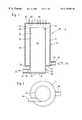
- FIG. 1shows a longitudinal section through a first embodiment of the device according to the present invention.
- FIG. 2shows a bottom view of the embodiment depicted in FIG. 1 .
- FIG. 3shows a longitudinal section through a second embodiment of the device according to the present invention.
- 10denotes a device for removing gases from medical fluids, in particular for removing air from a dialyzing fluid, said device having a container 12 .
- This container 12has a substantially vertically arranged container wall 14 , which is substantially circular in design in accordance with the specific embodiment shown in FIG. 1 .
- Container 12is delimited on its bottom side by a container bottom 16 and on its top side by a container cover 18 .
- container bottom 16is offset, forming a step 20 , through which means the container bottom is divided into an outer annular region 22 and an inner, substantially circular region 24 . Therefore, stepped region 20 forms a substantially cylindrical region 26 .
- Container 12has an inside space 28 , which is divided by a toroidally-closed partition wall 30 into a first chamber 32 , situated inside partition wall 30 , and a second chamber 34 , which has a substantially annular structure, surrounds partition wall 30 and is bounded by container wall 14 .
- Partition wall 30is secured to container bottom 16 and is so formed in accordance with the specific embodiment shown in FIG. 1 that, at annular bottom region 22 , it passes over into cylindrical region 26 and coincides with this region.
- the entire bottom 16can also have a flat design, so that partition wall 30 stands on this bottom and is secured thereto.
- first orifice 38which is advantageously conceived as an intake orifice.
- this first orifice 38is positioned at downwardly projecting cylindrical region 26 .
- partition wall 30 opposite bottom 16is brought to the vicinity of the container cover and opens through there into a tubular orifice 39 , which is defined by a circumferential tubular rim 40 , functioning as a spillover weir for a supplied fluid. Provision is made between tubular rim 40 and container cover 18 for a gap-shaped flow space 42 , which provides for flow communication between first chamber 32 and second chamber 34 over tubular rim 40 .
- container 12as well as its container wall 14 and partition wall 30 is, for the most part, not critical.
- container 12 , container wall 14 and partition wall 30are preferably circular.
- the two divided chambers formed from container wall 14 and partition wall 30have a common circular center.
- Inner first chamber 32is advantageously constituted as an inlet chamber, while second chamber 34 lying concentrically to the outside functions as an outlet chamber.
- the outlet chamberadvantageously has a larger cross-section than the inlet chamber, so that the fluid is able to flow substantially unhindered over tubular rim 40 .
- no significant pressure differenceprevails.
- the containermay be designed for a different kind of incident flow, for example a flow from the outside to the inside, although this is not preferred.
- a first tube connector 44is arranged at first chamber 32 in the area of first tubular orifice 38 .
- the longitudinal tubular axis of tube connector 44leads tangentially into the circular form of first chamber 32 and extends substantially horizontally in the position of normal use.
- second tube connector 46which functions as an outlet connector, its axis likewise being advantageously disposed horizontally in the position of normal use.
- container cover 18has a venting orifice 48 , which is sealed by a vent unit.
- the vent unitis a microporous, hydrophobic filter 50 , which allows the passage of the separated gas, but does not permit the passage of the aqueous fluid.
- the hydrophobic filteris concerned, reference is made to the disclosure of German Patent No. 32 15 003.
- Container 52 of FIG. 3differs from the specific embodiment shown in FIG. 1 merely in that container cover 54 is tapered conically toward the top in the direction of venting orifice 48 and in that venting orifice 48 has a boost pressure valve 56 as a vent unit, which is able to be connected via a line 58 to a hydraulic unit (not shown).
- Containers 12 and 52are usually made of a plastic material and function as primary air separators, for example, for separating out air in the preparation of dialyzing fluid.
- the air dissolved physically in the fluidis initially released from the freshly prepared fluid in a low pressure system.
- the fluid-air mixtureis fed to tube connector 44 , the mixture moving helically upwards because of the tangential introduction and, as a result, the air being automatically separated from the fluid in the direction of the body axis thereby forming small air bubbles.
- the air separationfollows then in the area of hydrophobic membrane 50 , i.e., of boost pressure valve 56 .
- a considerable advantage of the device according to the invention for removing gasesis the simple, continuous, very efficient separation of air, particularly when working with single-pass dialysis.
- a further advantageis that the container of the device is constantly filled with fluid, the result being very good disinfection or thorough flushing out of the system.
- the device according to the inventioncan be reduced in size by about half as compared to air separators currently in use.
Landscapes
- Health & Medical Sciences (AREA)
- Heart & Thoracic Surgery (AREA)
- Urology & Nephrology (AREA)
- Hematology (AREA)
- Animal Behavior & Ethology (AREA)
- Engineering & Computer Science (AREA)
- Anesthesiology (AREA)
- Biomedical Technology (AREA)
- Emergency Medicine (AREA)
- Life Sciences & Earth Sciences (AREA)
- Vascular Medicine (AREA)
- General Health & Medical Sciences (AREA)
- Public Health (AREA)
- Veterinary Medicine (AREA)
- External Artificial Organs (AREA)
- Degasification And Air Bubble Elimination (AREA)
- Treating Waste Gases (AREA)
- Separation Using Semi-Permeable Membranes (AREA)
Abstract
Description
The invention relates to a device for removing gases from fluids, in particular from a dialyzing fluid.
When setting up an extracorporeal blood circuit, as well as when preparing dialyzing fluids for dialysis, a plurality of devices for separating out air are known, such as bubble traps or air-venting devices, whose task is to effectively separate out the gases, which are present and partly dissolved in the fluid from the fluid.
The dialyzing fluids used in dialysis release gases in response to low pressure air separators which usually include a laterally disposed upper inlet, whose intended use is to impress a helical path upon the inflowing fluid. In this context, the air bubbles are to be separated out through a hydrophobic filter situated at the top. An arrangement of this kind is disclosed, for example, by the German Patent No. 32 15 003. However, in practical use, it was determined that the suction created partly entrains the separated air into the outflow so that further precautions had to be taken to improve the separation. Thus, for example, separation aids in the form of small plates were introduced into the venting space. Furthermore, the air separators were often built with very long dimensions to form the largest possible separation surface.
A device is disclosed in U.S. Pat. No. 4,061,031 that can be used both as a flow meter as well as an air separator. The known device has a container, which is divided by a partition wall that includes two chambers, one chamber being provided with an inlet orifice, and the other chamber with an outlet orifice. The partition wall includes an opening, and extends from the bottom of the container up to near the container cover, forming a gap-shaped interstitial space between the inlet chamber and the outlet chamber as well as the container cover.
The cut-through partition wall is comprised of two plate-shaped elements in a staggered arrangement, the orifices of the inlet and outlet chambers being situated at the bottom of the container. Since the opening in the partition wall has a smaller cross-section than the inlet orifice, fluid columns of different heights form in the chambers, making it possible to measure the flow rate. In this context, the difference between the two fluid columns is a measure of the level of the flow rate.
In the known device, the two chambers function as bubble traps. The air bubbles entrapped in the fluid rise to the top of the chambers and remain as gas above the fluid level. An active separation is no longer possible when working with the known device. To keep the fluid from flowing over the top edge of the partition wall into the outlet chamber, the inlet chamber has an elongated shape, which leads to a relatively substantial overall height.
It is the underlying object of the invention to create a device for removing gases from fluids, which, with a compact and simple type of construction, will enable a high separation rate to be attained.
In the device according to the invention, the partition wall is formed as a continuous traversing body, so that the first orifice and the second orifice are in fluid communication only via a gap-shaped interstitial space. Furthermore, provision is made on the container cover for a venting orifice that is sealed by a vent unit, which permits gas to pass through, but not fluid. During operation, the container, i.e., the two chambers and the gap-shaped interstitial space, are completely filled with fluid. The is fluid to be degassed flows out of the one chamber, across the gap-shaped interstitial space beneath the container cover, into the other chamber. At the partition wall, a reversal of the flow direction takes place, the gases entrapped in the fluid are able to escape through the venting orifice provided on the container cover.
An especially high separation rate is achieved with a device of a compact design, particularly when the partition wall is conceived in the form of a hollow body, which, while forming the first and second chamber, is so arranged inside the container that the inner first chamber has a smaller cross-section than the outer second chamber. In this arrangement, the first chamber forms the inlet chamber and the second chamber the outlet chamber. Since the inlet chamber has a smaller cross-section than the outlet chamber, the flow rate in the first chamber and, thus, the static pressure acting on the venting orifice is increased. On the other hand, the dynamic pressure at the venting orifice is kept low, so that in spite of the increased flow rate in the first chamber, virtually no air is entrained.
In the device according to the invention, the vent unit can be designed, for example, as a hydrophobic membrane. This membrane is advantageously integrated in the container cover, so that the fluid to be degassed is pressed against the membrane. The hydrophobic membrane should form the largest possible working surface for the fluid and preferably extend nearly over the entire cross-sectional surface of the gap-shaped interstitial space.
In one preferred specific embodiment, provision is made for the influx of fluid to be able to take place horizontally into the first orifice to the first chamber, this horizontal influx of fluid advantageously provides a tangential flow component. As a result, the inflowing fluid is essentially carried upwards in a spiral shape, thereby improving the air separation. Thus, the inflowing fluid mixture is set into a rotational motion within the air separator according to the invention, through which means gas is automatically conveyed in the direction of the shared axis.
In another preferred specific embodiment, the bottom of the tubular inside part of the first chamber is elongated toward the lower end with respect to the bottom of the outside part of the second chamber and, accordingly, extends out downwardly. In this specific embodiment, the first orifice is arranged on the tubular side wall adjacent to the bottom and the intake connector is in fluid communication with the first orifice. Preferably, the connector is advantageously positioned tangentially to the partition wall.
Similarly, the outflow connector in fluid communication with the second orifice can likewise be arranged horizontally adjacent to the bottom of the container and open through into the second orifice. The outflow connector is preferably positioned tangentially to the container wall.
Especially preferred is the specific embodiment where the horizontal walls of the first chamber and of the second chamber are formed in an annular shape and, thus, constitute a tube-in-tube arrangement, so that a circular annular space is formed between the first chamber and the second chamber.
FIG. 1 shows a longitudinal section through a first embodiment of the device according to the present invention.
FIG. 2 shows a bottom view of the embodiment depicted in FIG.1.
FIG. 3 shows a longitudinal section through a second embodiment of the device according to the present invention.
In FIG. 1,10 denotes a device for removing gases from medical fluids, in particular for removing air from a dialyzing fluid, said device having acontainer 12. Thiscontainer 12 has a substantially vertically arrangedcontainer wall 14, which is substantially circular in design in accordance with the specific embodiment shown in FIG.1.Container 12 is delimited on its bottom side by acontainer bottom 16 and on its top side by acontainer cover 18.
In accordance with the specific embodiment shown in FIG. 1,container bottom 16 is offset, forming astep 20, through which means the container bottom is divided into an outerannular region 22 and an inner, substantiallycircular region 24. Therefore, steppedregion 20 forms a substantiallycylindrical region 26.
In the area ofbottom 16, provision is made in the area offirst chamber 32 for afirst orifice 38, which is advantageously conceived as an intake orifice. In accordance with the specific embodiment shown in FIG. 1, thisfirst orifice 38 is positioned at downwardly projectingcylindrical region 26.
The end ofpartition wall 30 oppositebottom 16 is brought to the vicinity of the container cover and opens through there into atubular orifice 39, which is defined by a circumferential tubular rim40, functioning as a spillover weir for a supplied fluid. Provision is made between tubular rim40 andcontainer cover 18 for a gap-shaped flow space 42, which provides for flow communication betweenfirst chamber 32 andsecond chamber 34 over tubular rim40.
The cross-sectional shape ofcontainer 12 as well as itscontainer wall 14 andpartition wall 30 is, for the most part, not critical. However,container 12,container wall 14 andpartition wall 30 are preferably circular. Preferably, the two divided chambers formed fromcontainer wall 14 andpartition wall 30 have a common circular center.
Innerfirst chamber 32 is advantageously constituted as an inlet chamber, whilesecond chamber 34 lying concentrically to the outside functions as an outlet chamber. In this context, the outlet chamber advantageously has a larger cross-section than the inlet chamber, so that the fluid is able to flow substantially unhindered over tubular rim40. In the container, as a whole, no significant pressure difference prevails.
It should also be added here, however, that the container may be designed for a different kind of incident flow, for example a flow from the outside to the inside, although this is not preferred.
In accordance with the specific embodiment of FIGS. 1 and 2, afirst tube connector 44 is arranged atfirst chamber 32 in the area of firsttubular orifice 38. In this context, the longitudinal tubular axis oftube connector 44—as is apparent from FIG. 2 leads tangentially into the circular form offirst chamber 32 and extends substantially horizontally in the position of normal use.
In addition, arranged atsecond chamber 34 in the area ofsecond orifice 36 is asecond tube connector 46, which functions as an outlet connector, its axis likewise being advantageously disposed horizontally in the position of normal use.
The arrows indicated attube connectors
In addition,container cover 18 has a ventingorifice 48, which is sealed by a vent unit. In the specific embodiment shown in FIG. 1, the vent unit is a microporous,hydrophobic filter 50, which allows the passage of the separated gas, but does not permit the passage of the aqueous fluid. To the extent that the hydrophobic filter is concerned, reference is made to the disclosure of German Patent No. 32 15 003.
The air separation follows then in the area ofhydrophobic membrane 50, i.e., ofboost pressure valve 56.
A considerable advantage of the device according to the invention for removing gases is the simple, continuous, very efficient separation of air, particularly when working with single-pass dialysis. A further advantage is that the container of the device is constantly filled with fluid, the result being very good disinfection or thorough flushing out of the system. Finally, because of its excellent separation properties, the device according to the invention can be reduced in size by about half as compared to air separators currently in use.
Claims (13)
1. A device for removing gases from fluids comprising:
a substantially cylindrical container having a side surface, a top end and a bottom end;
a substantially cylindrical partition wall positioned in the container to divide the container into a first chamber, a second chamber, and an interstitial space substantially above the first and second chambers, wherein the first chamber is in fluid communication with the second chamber via the interstitial space;
a cover positioned substantially at the top end of the container and including a hydrophobic membrane which permits passage of gas from the container while the container is completely filled with fluid such that the fluid is pressed against the hydrophobic membrane;
a first orifice formed on the partition wall adjacent to a bottom of the first chamber; and
a second orifice formed on the side surface adjacent a bottom of the second chamber.
2. The device according to claim1, wherein the partition wall extends from the bottom end of the container to substantially to the cover.
3. The device according to claim2, wherein the diameter of the cross-section of the first chamber is smaller than the diameter of the cross-section of the second chamber.
4. The device according to claim1, wherein a first connector is in fluid communication with a first orifice of the first chamber; a second connector is in fluid communication with a second orifice of the second chamber; and wherein the first connector and the second connector extend in opposite directions substantially horizontal to the first orifice and the second orifice.
5. The device according to claim4, wherein the first connector is in fluid communication with the first orifice of the container and directs a rotational fluid flow into the first chamber.
6. The device according to claim1, wherein the sealing member is a hydrophobic membrane.
7. The device according to claim1, wherein the second chamber has an outlet orifice.
8. The device according to claim1, wherein the partition wall is toroidally-closed.
9. The device according to claim1, wherein the fluids are medical fluids.
10. The device according to claim1, wherein the fluids are dialysis fluids.
11. The device according to claim1, wherein the first chamber is in fluid connection with the second chamber only via the interstitial space.
12. A method for removing gases from fluids comprising the steps of:
passing fluid into a substantially cylindrical first chamber of a container, the container having a partition wall dividing the container into the first chamber, a second substantially cylindrical chamber and an interstitial space substantially above the first and second chambers, the fluid passing through a first orifice formed in the partition wall adjacent a bottom of the first chamber;
flowing the fluid from the first chamber over a top of the partition wall into the second chamber;
removing air from the fluid through a hydrophobic membrane positioned substantially at a top end of the container while the container is completely filled with fluid such that the fluid is pressed against the hydrophobic membrane; and
passing the fluid out of the second chamber through a second orifice formed in a side surface of the container, adjacent a bottom of the second chamber.
13. The method as recited in claim12 wherein the passing the fluid step creates a rotational fluid flow in the first chamber.
Applications Claiming Priority (2)
| Application Number | Priority Date | Filing Date | Title |
|---|---|---|---|
| DE19620591ADE19620591B4 (en) | 1996-05-22 | 1996-05-22 | Device for removing gases from liquids |
| DE19620591 | 1996-05-22 |
Publications (1)
| Publication Number | Publication Date |
|---|---|
| US6176903B1true US6176903B1 (en) | 2001-01-23 |
Family
ID=7795005
Family Applications (1)
| Application Number | Title | Priority Date | Filing Date |
|---|---|---|---|
| US08/861,543Expired - Fee RelatedUS6176903B1 (en) | 1996-05-22 | 1997-05-22 | Device for removing gases from fluids |
Country Status (6)
| Country | Link |
|---|---|
| US (1) | US6176903B1 (en) |
| EP (1) | EP0808633B1 (en) |
| JP (1) | JP4307576B2 (en) |
| AT (1) | ATE226457T1 (en) |
| DE (2) | DE19620591B4 (en) |
| ES (1) | ES2185834T3 (en) |
Cited By (37)
| Publication number | Priority date | Publication date | Assignee | Title |
|---|---|---|---|---|
| US6451257B1 (en)* | 1999-09-16 | 2002-09-17 | Terumo Kabushiki Kaisha | Arterial blood filter |
| US20030141018A1 (en)* | 2002-01-28 | 2003-07-31 | Applied Materials, Inc. | Electroless deposition apparatus |
| US6623698B2 (en) | 2001-03-12 | 2003-09-23 | Youti Kuo | Saliva-monitoring biosensor electrical toothbrush |
| US20030232228A1 (en)* | 2002-06-17 | 2003-12-18 | Grasso Albert P. | Coolant mixture separator assembly for use in a polymer electrolyte membrane (PEM) fuel cell power plant |
| US20040194627A1 (en)* | 2003-04-04 | 2004-10-07 | United Technologies Corporation | System and method for thermal management |
| WO2005044341A1 (en)* | 2003-11-07 | 2005-05-19 | Gambro Lundia Ab | Integrated blood treatment module |
| US20050247203A1 (en)* | 2002-06-24 | 2005-11-10 | Jacques Chevallet | Gas separation devices |
| US20060065046A1 (en)* | 2004-09-24 | 2006-03-30 | Battiston Felice M | Measurement cell and method for the analysis of liquids |
| US20070056889A1 (en)* | 2005-09-09 | 2007-03-15 | Cds Technologies, Inc. | Apparatus for separating solids from flowing liquids |
| US7314453B2 (en) | 2001-05-14 | 2008-01-01 | Youti Kuo | Handheld diagnostic device with renewable biosensor |
| US20080287887A1 (en)* | 2007-05-16 | 2008-11-20 | Smiths Medical Asd, Inc. | Pump Module For Use In A Medical Fluid Dispensing System |
| US20090084721A1 (en)* | 2007-10-01 | 2009-04-02 | Baxter International Inc. | Dialysis systems having air separation chambers with internal structures to enhance air removal |
| US20090084719A1 (en)* | 2007-10-01 | 2009-04-02 | Baxter International Inc. | Dialysis systems having air separation chambers with internal structures to enhance air removal |
| US20090084718A1 (en)* | 2007-10-01 | 2009-04-02 | Baxter International Inc. | Dialysis systems having air traps with internal structures to enhance air removal |
| US20090084720A1 (en)* | 2003-11-24 | 2009-04-02 | Jurgen Dannenmaier | Degassing Device and End-Cap Assembly for a Filter Including such a Degassing Device |
| US20090088675A1 (en)* | 2007-10-01 | 2009-04-02 | Baxter International Inc. | Fluid and air handling in blood and dialysis circuits |
| US20090101576A1 (en)* | 2007-10-22 | 2009-04-23 | Baxter International Inc. | Priming and air removal systems and methods for dialysis |
| CN100586494C (en)* | 2003-11-07 | 2010-02-03 | 甘布罗伦迪亚股份公司 | Integrated blood treatment module |
| US20110092875A1 (en)* | 2008-04-30 | 2011-04-21 | Gambro Lundia Ab | Degassing device |
| US8114276B2 (en) | 2007-10-24 | 2012-02-14 | Baxter International Inc. | Personal hemodialysis system |
| US8382711B2 (en) | 2010-12-29 | 2013-02-26 | Baxter International Inc. | Intravenous pumping air management systems and methods |
| US20140298991A1 (en)* | 2013-04-08 | 2014-10-09 | Hamilton Sundstrand Space Systems International Inc. | Vortex separator and separation method |
| AU2015200177B2 (en)* | 2008-10-30 | 2016-01-28 | Porous Media Corporation | Venting and filtration systems with gas permeable membrane |
| US9486590B2 (en) | 2014-09-29 | 2016-11-08 | Fenwal, Inc. | Automatic purging of air from a fluid processing system |
| EP3266477A4 (en)* | 2015-03-03 | 2018-09-05 | Nikkiso Company Limited | Air trap chamber |
| US10179200B2 (en) | 2002-07-19 | 2019-01-15 | Baxter International Inc. | Disposable cassette and system for dialysis |
| CN109954181A (en)* | 2017-12-25 | 2019-07-02 | 涩谷工业株式会社 | Degasser |
| EP3520837A1 (en)* | 2008-01-18 | 2019-08-07 | Fresenius Medical Care Holdings, Inc. | A wearable dialysis system |
| US10589008B2 (en) | 2014-08-29 | 2020-03-17 | Fresenius Kabi Deutschland Gmbh | Tubing set for use in a blood processing apparatus |
| CN111050820A (en)* | 2017-09-11 | 2020-04-21 | 费森尤斯医疗保健控股公司 | Hydrophobic filters for air management in dialysis machines |
| US10625009B2 (en) | 2016-02-17 | 2020-04-21 | Baxter International Inc. | Airtrap, system and method for removing microbubbles from a fluid stream |
| US10646634B2 (en) | 2008-07-09 | 2020-05-12 | Baxter International Inc. | Dialysis system and disposable set |
| US11396893B2 (en)* | 2018-10-19 | 2022-07-26 | Robert Bosch Gmbh | Tank for a hydraulic unit |
| US11495334B2 (en) | 2015-06-25 | 2022-11-08 | Gambro Lundia Ab | Medical device system and method having a distributed database |
| US11516183B2 (en) | 2016-12-21 | 2022-11-29 | Gambro Lundia Ab | Medical device system including information technology infrastructure having secure cluster domain supporting external domain |
| US20230042212A1 (en)* | 2019-12-25 | 2023-02-09 | Fresenius Medical Care Deutschland Gmbh | Pressure Vessel, Liquid Mixing Equipment, Liquid Mixing System, Method for Preparing Solution, Control System and Computer Readable Program Carrier |
| WO2023152008A1 (en)* | 2022-02-08 | 2023-08-17 | Fresenius Kabi Deutschland Gmbh | Infusion system for administering a fluid to a patient |
Families Citing this family (25)
| Publication number | Priority date | Publication date | Assignee | Title |
|---|---|---|---|---|
| DE19750062A1 (en) | 1997-11-12 | 1999-05-20 | Jostra Medizintechnik Ag | Device for the filtration and degassing of body fluids, especially blood |
| JP4839028B2 (en)* | 2005-07-06 | 2011-12-14 | テルモ株式会社 | Bubble removal device |
| JP4839030B2 (en)* | 2005-07-06 | 2011-12-14 | テルモ株式会社 | Extracorporeal circulation device |
| JP4839029B2 (en)* | 2005-07-06 | 2011-12-14 | テルモ株式会社 | Bubble removal device |
| JP2007275473A (en)* | 2006-04-11 | 2007-10-25 | Terumo Corp | Bubble removing device |
| JP2008018101A (en)* | 2006-07-13 | 2008-01-31 | Terumo Corp | Bubble removing device |
| US8597505B2 (en) | 2007-09-13 | 2013-12-03 | Fresenius Medical Care Holdings, Inc. | Portable dialysis machine |
| US9308307B2 (en) | 2007-09-13 | 2016-04-12 | Fresenius Medical Care Holdings, Inc. | Manifold diaphragms |
| US9358331B2 (en) | 2007-09-13 | 2016-06-07 | Fresenius Medical Care Holdings, Inc. | Portable dialysis machine with improved reservoir heating system |
| US8105487B2 (en) | 2007-09-25 | 2012-01-31 | Fresenius Medical Care Holdings, Inc. | Manifolds for use in conducting dialysis |
| US8240636B2 (en) | 2009-01-12 | 2012-08-14 | Fresenius Medical Care Holdings, Inc. | Valve system |
| CA3057807C (en) | 2007-11-29 | 2021-04-20 | Thomas P. Robinson | System and method for conducting hemodialysis and hemofiltration |
| US7712360B2 (en)* | 2007-12-13 | 2010-05-11 | Bausch & Lomb Incorporated | Air separator for ophthalmic surgical system |
| EP3586946B1 (en) | 2008-10-07 | 2023-03-29 | Fresenius Medical Care Holdings, Inc. | Priming system and method for dialysis systems |
| EA024555B1 (en) | 2008-10-30 | 2016-09-30 | Фрезениус Медикал Кеа Холдингс, Инк. | Modular, portable dialysis system |
| WO2010114932A1 (en) | 2009-03-31 | 2010-10-07 | Xcorporeal, Inc. | Modular reservoir assembly for a hemodialysis and hemofiltration system |
| AU2010238834B2 (en)* | 2009-04-23 | 2015-06-18 | Fresenius Medical Care Deutschland Gmbh | Device, external functional device and treatment device for treating medical fluids |
| US9201036B2 (en) | 2012-12-21 | 2015-12-01 | Fresenius Medical Care Holdings, Inc. | Method and system of monitoring electrolyte levels and composition using capacitance or induction |
| US9157786B2 (en) | 2012-12-24 | 2015-10-13 | Fresenius Medical Care Holdings, Inc. | Load suspension and weighing system for a dialysis machine reservoir |
| US9354640B2 (en) | 2013-11-11 | 2016-05-31 | Fresenius Medical Care Holdings, Inc. | Smart actuator for valve |
| JP6560743B2 (en)* | 2014-08-29 | 2019-08-14 | フレゼニウス カービ ドイチュラント ゲーエムベーハー | Blood processing apparatus equipped with a measuring device |
| JP6335333B2 (en) | 2014-12-25 | 2018-05-30 | アサヒカセイメディカルヨーロッパゲーエムベーハー | Solution generator and blood purification system |
| BR112018076718A2 (en)* | 2016-06-23 | 2019-04-02 | Medtronic, Inc. | arterial air capture chamber |
| JP6799734B2 (en)* | 2018-03-12 | 2020-12-16 | 国立研究開発法人産業技術総合研究所 | Gas production system and gas production method |
| JP2022134386A (en)* | 2021-03-03 | 2022-09-15 | 国立研究開発法人宇宙航空研究開発機構 | Gas-liquid separator, gas-liquid separation method, electrolyzer, electrolysis method |
Citations (18)
| Publication number | Priority date | Publication date | Assignee | Title |
|---|---|---|---|---|
| US3088595A (en)* | 1959-10-07 | 1963-05-07 | British Oxygen Co Ltd | Filter unit |
| US3771288A (en)* | 1971-10-08 | 1973-11-13 | Tno | Device for degassing a liquid |
| US3827561A (en) | 1972-09-20 | 1974-08-06 | Milton Roy Co | Deaerator for dialysis system |
| US3920556A (en) | 1974-06-17 | 1975-11-18 | Donald B Bowman | Hemodialysis system |
| US4061031A (en) | 1975-11-05 | 1977-12-06 | Lars Grimsrud | Combination of flow meter and bubble trap |
| US4279626A (en)* | 1979-06-07 | 1981-07-21 | Messer Griesheim Gmbh | Apparatus for separating the gas which evaporates during the transfer of low-boiling liquified gases |
| US4344777A (en) | 1980-01-07 | 1982-08-17 | Siposs George G | Directed flow bubble trap for arterial blood |
| US4368118A (en) | 1980-01-07 | 1983-01-11 | Siposs George G | Blood-air separator and filter |
| DE3215003A1 (en) | 1982-04-22 | 1983-11-03 | Fresenius AG, 6380 Bad Homburg | DIALYSIS DEVICE WITH IMPROVED AIR DEPOSITION |
| SU1212467A1 (en)* | 1983-12-27 | 1986-02-23 | МВТУ им.Н.Э.Баумана | Vortex-type liquid deaerator |
| SU1327909A1 (en)* | 1985-12-27 | 1987-08-07 | Коми Государственный Проектный И Научно-Исследовательский Институт Лесной Промышленности | Apparatus for degassing liquid |
| US4690762A (en)* | 1983-06-10 | 1987-09-01 | Terumo Kabushiki Kaisha | Apparatus for removing bubbles from a liquid |
| US4860591A (en)* | 1987-01-26 | 1989-08-29 | Societe Nationale Elf Aquitaine (Production) | Gas-liquid separation and flow measurement apparatus |
| SU1699496A1 (en)* | 1989-11-27 | 1991-12-23 | Конструкторское Бюро Транспортно-Химического Машиностроения | Eddy liquid deaerator |
| US5203891A (en)* | 1992-04-03 | 1993-04-20 | The United States Of America As Represented By The Secretary Of The Navy | Gas/liquid separator |
| US5468388A (en)* | 1993-07-01 | 1995-11-21 | Sartorius Ag | Filter module with degassing feature |
| US5622545A (en)* | 1995-04-21 | 1997-04-22 | Claude Laval Corporation | Separator for removing gases from water |
| US5849065A (en)* | 1996-04-27 | 1998-12-15 | Fresenius Ag | Device for separating gas bubbles from fluids, in particular blood |
Family Cites Families (2)
| Publication number | Priority date | Publication date | Assignee | Title |
|---|---|---|---|---|
| US4681606A (en)* | 1986-02-26 | 1987-07-21 | Cobe Laboratories, Inc. | Drip chamber |
| DE9415480U1 (en)* | 1994-09-24 | 1996-02-01 | AEG Hausgeräte GmbH, 90429 Nürnberg | Venting device for liquid-carrying hollow components |
- 1996
- 1996-05-22DEDE19620591Apatent/DE19620591B4/ennot_activeExpired - Fee Related
- 1997
- 1997-05-17ESES97108082Tpatent/ES2185834T3/ennot_activeExpired - Lifetime
- 1997-05-17ATAT97108082Tpatent/ATE226457T1/enactive
- 1997-05-17EPEP97108082Apatent/EP0808633B1/ennot_activeExpired - Lifetime
- 1997-05-17DEDE59708524Tpatent/DE59708524D1/ennot_activeExpired - Lifetime
- 1997-05-22USUS08/861,543patent/US6176903B1/ennot_activeExpired - Fee Related
- 1997-05-22JPJP13264197Apatent/JP4307576B2/ennot_activeExpired - Fee Related
Patent Citations (18)
| Publication number | Priority date | Publication date | Assignee | Title |
|---|---|---|---|---|
| US3088595A (en)* | 1959-10-07 | 1963-05-07 | British Oxygen Co Ltd | Filter unit |
| US3771288A (en)* | 1971-10-08 | 1973-11-13 | Tno | Device for degassing a liquid |
| US3827561A (en) | 1972-09-20 | 1974-08-06 | Milton Roy Co | Deaerator for dialysis system |
| US3920556A (en) | 1974-06-17 | 1975-11-18 | Donald B Bowman | Hemodialysis system |
| US4061031A (en) | 1975-11-05 | 1977-12-06 | Lars Grimsrud | Combination of flow meter and bubble trap |
| US4279626A (en)* | 1979-06-07 | 1981-07-21 | Messer Griesheim Gmbh | Apparatus for separating the gas which evaporates during the transfer of low-boiling liquified gases |
| US4344777A (en) | 1980-01-07 | 1982-08-17 | Siposs George G | Directed flow bubble trap for arterial blood |
| US4368118A (en) | 1980-01-07 | 1983-01-11 | Siposs George G | Blood-air separator and filter |
| DE3215003A1 (en) | 1982-04-22 | 1983-11-03 | Fresenius AG, 6380 Bad Homburg | DIALYSIS DEVICE WITH IMPROVED AIR DEPOSITION |
| US4690762A (en)* | 1983-06-10 | 1987-09-01 | Terumo Kabushiki Kaisha | Apparatus for removing bubbles from a liquid |
| SU1212467A1 (en)* | 1983-12-27 | 1986-02-23 | МВТУ им.Н.Э.Баумана | Vortex-type liquid deaerator |
| SU1327909A1 (en)* | 1985-12-27 | 1987-08-07 | Коми Государственный Проектный И Научно-Исследовательский Институт Лесной Промышленности | Apparatus for degassing liquid |
| US4860591A (en)* | 1987-01-26 | 1989-08-29 | Societe Nationale Elf Aquitaine (Production) | Gas-liquid separation and flow measurement apparatus |
| SU1699496A1 (en)* | 1989-11-27 | 1991-12-23 | Конструкторское Бюро Транспортно-Химического Машиностроения | Eddy liquid deaerator |
| US5203891A (en)* | 1992-04-03 | 1993-04-20 | The United States Of America As Represented By The Secretary Of The Navy | Gas/liquid separator |
| US5468388A (en)* | 1993-07-01 | 1995-11-21 | Sartorius Ag | Filter module with degassing feature |
| US5622545A (en)* | 1995-04-21 | 1997-04-22 | Claude Laval Corporation | Separator for removing gases from water |
| US5849065A (en)* | 1996-04-27 | 1998-12-15 | Fresenius Ag | Device for separating gas bubbles from fluids, in particular blood |
Cited By (96)
| Publication number | Priority date | Publication date | Assignee | Title |
|---|---|---|---|---|
| US6451257B1 (en)* | 1999-09-16 | 2002-09-17 | Terumo Kabushiki Kaisha | Arterial blood filter |
| US6623698B2 (en) | 2001-03-12 | 2003-09-23 | Youti Kuo | Saliva-monitoring biosensor electrical toothbrush |
| US7314453B2 (en) | 2001-05-14 | 2008-01-01 | Youti Kuo | Handheld diagnostic device with renewable biosensor |
| US20030141018A1 (en)* | 2002-01-28 | 2003-07-31 | Applied Materials, Inc. | Electroless deposition apparatus |
| US7138014B2 (en)* | 2002-01-28 | 2006-11-21 | Applied Materials, Inc. | Electroless deposition apparatus |
| US20050199489A1 (en)* | 2002-01-28 | 2005-09-15 | Applied Materials, Inc. | Electroless deposition apparatus |
| US20060083969A1 (en)* | 2002-06-17 | 2006-04-20 | Grasso Albert P | Coolant mixture separator assembly for use in a polymer electrolyte membrane (PEM) fuel cell power plant |
| US20030232228A1 (en)* | 2002-06-17 | 2003-12-18 | Grasso Albert P. | Coolant mixture separator assembly for use in a polymer electrolyte membrane (PEM) fuel cell power plant |
| US7670702B2 (en)* | 2002-06-17 | 2010-03-02 | Utc Power Corp. | Coolant mixture separator assembly for use in a polymer electrolyte membrane (PEM) fuel cell power plant |
| US7172647B2 (en)* | 2002-06-17 | 2007-02-06 | Utc Fuel Cells, Llc | Coolant mixture separator assembly for use in a polymer electrolyte membrane (PEM) fuel cell power plant |
| US7118819B2 (en)* | 2002-06-17 | 2006-10-10 | Utc Fuel Cells Llc | Coolant mixture separator assembly for use in a polymer electrolyte membrane (PEM) fuel cell power plant |
| US20060035127A1 (en)* | 2002-06-17 | 2006-02-16 | Grasso Albert P | Coolant mixture separator assembly for use in a polymer electrolyte membrane (PEM) fuel cell power plant |
| US7517387B2 (en) | 2002-06-24 | 2009-04-14 | Gambro Lundia Ab | Gas separation devices |
| US20050247203A1 (en)* | 2002-06-24 | 2005-11-10 | Jacques Chevallet | Gas separation devices |
| US11235094B2 (en) | 2002-07-19 | 2022-02-01 | Baxter International Inc. | System for peritoneal dialysis |
| US10363352B2 (en) | 2002-07-19 | 2019-07-30 | Baxter International Inc. | Disposable set and system for dialysis |
| US10179200B2 (en) | 2002-07-19 | 2019-01-15 | Baxter International Inc. | Disposable cassette and system for dialysis |
| US20040194627A1 (en)* | 2003-04-04 | 2004-10-07 | United Technologies Corporation | System and method for thermal management |
| US6939392B2 (en) | 2003-04-04 | 2005-09-06 | United Technologies Corporation | System and method for thermal management |
| CN100586494C (en)* | 2003-11-07 | 2010-02-03 | 甘布罗伦迪亚股份公司 | Integrated blood treatment module |
| CN1874804B (en)* | 2003-11-07 | 2010-08-25 | 甘布罗伦迪亚股份公司 | Fluid distribution module and extracorporeal blood circuit including such a module |
| AU2004286782B2 (en)* | 2003-11-07 | 2010-08-26 | Gambro Lundia Ab | Fluid distribution module and extracorporeal blood circuit including such a module |
| US20090008310A1 (en)* | 2003-11-07 | 2009-01-08 | Jurgen Dannenmaier | Integrated blood treatment module |
| US8403150B2 (en) | 2003-11-07 | 2013-03-26 | Gambro Lundia Ab | End-cap assembly with pump hose for a filter and filter comprising such an end-cap assembly |
| WO2005044341A1 (en)* | 2003-11-07 | 2005-05-19 | Gambro Lundia Ab | Integrated blood treatment module |
| WO2005044340A1 (en)* | 2003-11-07 | 2005-05-19 | Gambro Lundia Ab | Fluid distribution module and extracorporeal blood circuit including such a module |
| EP1529545A3 (en)* | 2003-11-07 | 2005-06-01 | Gambro Lundia AB | Integrated blood treatment module |
| US8206580B2 (en) | 2003-11-07 | 2012-06-26 | Gambro Lundia Ab | Integrated blood treatment module |
| US8142383B2 (en) | 2003-11-07 | 2012-03-27 | Gambro Ab | Fluid distribution module and extracorporeal blood circuit including such a module |
| US20090084720A1 (en)* | 2003-11-24 | 2009-04-02 | Jurgen Dannenmaier | Degassing Device and End-Cap Assembly for a Filter Including such a Degassing Device |
| US8048209B2 (en) | 2003-11-24 | 2011-11-01 | Gambro Lundia Ab | Degassing device and end-cap assembly for a filter including such a degassing device |
| CN1878582B (en)* | 2003-11-24 | 2011-05-25 | 甘布罗伦迪亚股份公司 | Degassing device and end cap assembly for a filter having such a degassing device |
| US7389679B2 (en) | 2004-09-24 | 2008-06-24 | Concentris Gmbh | Measurement cell and method for the analysis of liquids |
| US20060065046A1 (en)* | 2004-09-24 | 2006-03-30 | Battiston Felice M | Measurement cell and method for the analysis of liquids |
| US20070056889A1 (en)* | 2005-09-09 | 2007-03-15 | Cds Technologies, Inc. | Apparatus for separating solids from flowing liquids |
| US7465391B2 (en)* | 2005-09-09 | 2008-12-16 | Cds Technologies, Inc. | Apparatus for separating solids from flowing liquids |
| US8876765B2 (en) | 2007-05-16 | 2014-11-04 | Smiths Medical Asd, Inc. | Pump module for use in a medical fluid dispensing system |
| US20080287887A1 (en)* | 2007-05-16 | 2008-11-20 | Smiths Medical Asd, Inc. | Pump Module For Use In A Medical Fluid Dispensing System |
| US8080091B2 (en) | 2007-10-01 | 2011-12-20 | Baxter International Inc. | Dialysis systems and methods including cassette with fluid heating and air removal |
| US7892331B2 (en)* | 2007-10-01 | 2011-02-22 | Baxter International Inc. | Dialysis systems having air separation chambers with internal structures to enhance air removal |
| US20110137237A1 (en)* | 2007-10-01 | 2011-06-09 | Baxter International Inc. | Dialysis systems and methods having vibration-aided air removal |
| US20110137236A1 (en)* | 2007-10-01 | 2011-06-09 | Baxter International Inc. | Fluid delivery systems and methods having floating baffle aided air removal |
| US20110144557A1 (en)* | 2007-10-01 | 2011-06-16 | Baxter International Inc. | Dialysis systems and methods including cassette with fluid heating and air removal |
| US7988768B2 (en) | 2007-10-01 | 2011-08-02 | Baxter International Inc. | Dialysis systems having spiraling fluid air separation chambers |
| US8025714B2 (en) | 2007-10-01 | 2011-09-27 | Baxter International Inc. | Dialysis systems and methods having vibration-aided air removal |
| US8025716B2 (en) | 2007-10-01 | 2011-09-27 | Baxter International Inc. | Fluid delivery systems and methods having floating baffle aided air removal |
| US7871462B2 (en) | 2007-10-01 | 2011-01-18 | Baxter International Inc. | Dialysis systems having air separation chambers with internal structures to enhance air removal |
| US12023428B2 (en) | 2007-10-01 | 2024-07-02 | Baxter International Inc. | Blood treatment air purging system and method |
| US7892332B2 (en) | 2007-10-01 | 2011-02-22 | Baxter International Inc. | Dialysis systems having air traps with internal structures to enhance air removal |
| US10653826B2 (en) | 2007-10-01 | 2020-05-19 | Baxter International Inc. | Blood treatment air purging systems |
| US20110092895A1 (en)* | 2007-10-01 | 2011-04-21 | Baxter International Inc. | Dialysis systems having spiraling fluid air separation chambers |
| US20090088675A1 (en)* | 2007-10-01 | 2009-04-02 | Baxter International Inc. | Fluid and air handling in blood and dialysis circuits |
| US8221529B2 (en) | 2007-10-01 | 2012-07-17 | Baxter International | Dialysis systems and methods including cassette with air removal |
| US10391228B2 (en) | 2007-10-01 | 2019-08-27 | Baxter International Inc. | Air purging systems for blood treatments |
| US20090084718A1 (en)* | 2007-10-01 | 2009-04-02 | Baxter International Inc. | Dialysis systems having air traps with internal structures to enhance air removal |
| US20090084719A1 (en)* | 2007-10-01 | 2009-04-02 | Baxter International Inc. | Dialysis systems having air separation chambers with internal structures to enhance air removal |
| US20090084721A1 (en)* | 2007-10-01 | 2009-04-02 | Baxter International Inc. | Dialysis systems having air separation chambers with internal structures to enhance air removal |
| US8444587B2 (en) | 2007-10-01 | 2013-05-21 | Baxter International Inc. | Fluid and air handling in blood and dialysis circuits |
| US9795731B2 (en) | 2007-10-01 | 2017-10-24 | Baxter International Inc. | Blood treatment air purging methods |
| US8834403B2 (en) | 2007-10-01 | 2014-09-16 | Baxter International Inc. | Fluid and air handling in blood and dialysis circuits |
| US8123947B2 (en) | 2007-10-22 | 2012-02-28 | Baxter International Inc. | Priming and air removal systems and methods for dialysis |
| US20090101576A1 (en)* | 2007-10-22 | 2009-04-23 | Baxter International Inc. | Priming and air removal systems and methods for dialysis |
| US8323492B2 (en) | 2007-10-24 | 2012-12-04 | Baxter International Inc. | Hemodialysis system having clamping mechanism for peristaltic pumping |
| US11975129B2 (en) | 2007-10-24 | 2024-05-07 | Baxter International Inc. | Hemodialysis system including a disposable set and a dialysis instrument |
| US10695479B2 (en) | 2007-10-24 | 2020-06-30 | Baxter International Inc. | Renal therapy machine and method including a priming sequence |
| US8114276B2 (en) | 2007-10-24 | 2012-02-14 | Baxter International Inc. | Personal hemodialysis system |
| US8932469B2 (en) | 2007-10-24 | 2015-01-13 | Baxter International Inc. | Personal hemodialysis system including priming sequence and methods of same |
| US11291752B2 (en) | 2007-10-24 | 2022-04-05 | Baxter International Inc. | Hemodialysis system including a disposable set and a dialysis instrument |
| US9855377B2 (en) | 2007-10-24 | 2018-01-02 | Baxter International Inc. | Dialysis system including heparin injection |
| US9925320B2 (en) | 2007-10-24 | 2018-03-27 | Baxter International Inc. | Renal therapy machine and system including a priming sequence |
| US8329030B2 (en) | 2007-10-24 | 2012-12-11 | Baxter International Inc. | Hemodialysis system with cassette and pinch clamp |
| US8834719B2 (en) | 2007-10-24 | 2014-09-16 | Baxter International Inc. | Personal hemodialysis system |
| EP3520837A1 (en)* | 2008-01-18 | 2019-08-07 | Fresenius Medical Care Holdings, Inc. | A wearable dialysis system |
| US8444586B2 (en)* | 2008-04-30 | 2013-05-21 | Gambro Lundia Ab | Degassing device |
| US20110092875A1 (en)* | 2008-04-30 | 2011-04-21 | Gambro Lundia Ab | Degassing device |
| US11918721B2 (en) | 2008-07-09 | 2024-03-05 | Baxter International Inc. | Dialysis system having adaptive prescription management |
| US10646634B2 (en) | 2008-07-09 | 2020-05-12 | Baxter International Inc. | Dialysis system and disposable set |
| US11311658B2 (en) | 2008-07-09 | 2022-04-26 | Baxter International Inc. | Dialysis system having adaptive prescription generation |
| AU2015200177B2 (en)* | 2008-10-30 | 2016-01-28 | Porous Media Corporation | Venting and filtration systems with gas permeable membrane |
| US8382711B2 (en) | 2010-12-29 | 2013-02-26 | Baxter International Inc. | Intravenous pumping air management systems and methods |
| US10112009B2 (en) | 2010-12-29 | 2018-10-30 | Baxter International Inc. | Intravenous pumping air management systems and methods |
| US9084858B2 (en) | 2010-12-29 | 2015-07-21 | Baxter International Inc. | Intravenous pumping air management systems and methods |
| US20140298991A1 (en)* | 2013-04-08 | 2014-10-09 | Hamilton Sundstrand Space Systems International Inc. | Vortex separator and separation method |
| US9084946B2 (en)* | 2013-04-08 | 2015-07-21 | Hamilton Sundstrand Space Systems International Inc. | Vortex separator and separation method |
| US10589008B2 (en) | 2014-08-29 | 2020-03-17 | Fresenius Kabi Deutschland Gmbh | Tubing set for use in a blood processing apparatus |
| US9486590B2 (en) | 2014-09-29 | 2016-11-08 | Fenwal, Inc. | Automatic purging of air from a fluid processing system |
| EP3266477A4 (en)* | 2015-03-03 | 2018-09-05 | Nikkiso Company Limited | Air trap chamber |
| US11495334B2 (en) | 2015-06-25 | 2022-11-08 | Gambro Lundia Ab | Medical device system and method having a distributed database |
| US10625009B2 (en) | 2016-02-17 | 2020-04-21 | Baxter International Inc. | Airtrap, system and method for removing microbubbles from a fluid stream |
| US11516183B2 (en) | 2016-12-21 | 2022-11-29 | Gambro Lundia Ab | Medical device system including information technology infrastructure having secure cluster domain supporting external domain |
| US10806842B2 (en)* | 2017-09-11 | 2020-10-20 | Fresenius Medical Care Holdings, Inc. | Hydrophobic filters for air management in dialysis machines |
| CN111050820A (en)* | 2017-09-11 | 2020-04-21 | 费森尤斯医疗保健控股公司 | Hydrophobic filters for air management in dialysis machines |
| CN109954181A (en)* | 2017-12-25 | 2019-07-02 | 涩谷工业株式会社 | Degasser |
| US11396893B2 (en)* | 2018-10-19 | 2022-07-26 | Robert Bosch Gmbh | Tank for a hydraulic unit |
| US20230042212A1 (en)* | 2019-12-25 | 2023-02-09 | Fresenius Medical Care Deutschland Gmbh | Pressure Vessel, Liquid Mixing Equipment, Liquid Mixing System, Method for Preparing Solution, Control System and Computer Readable Program Carrier |
| WO2023152008A1 (en)* | 2022-02-08 | 2023-08-17 | Fresenius Kabi Deutschland Gmbh | Infusion system for administering a fluid to a patient |
Also Published As
| Publication number | Publication date |
|---|---|
| EP0808633B1 (en) | 2002-10-23 |
| JP4307576B2 (en) | 2009-08-05 |
| DE59708524D1 (en) | 2002-11-28 |
| ES2185834T3 (en) | 2003-05-01 |
| EP0808633A2 (en) | 1997-11-26 |
| DE19620591B4 (en) | 2004-08-26 |
| EP0808633A3 (en) | 1998-07-15 |
| ATE226457T1 (en) | 2002-11-15 |
| JPH1080602A (en) | 1998-03-31 |
| DE19620591A1 (en) | 1997-11-27 |
Similar Documents
| Publication | Publication Date | Title |
|---|---|---|
| US6176903B1 (en) | Device for removing gases from fluids | |
| US4919802A (en) | Blood filter | |
| US5849065A (en) | Device for separating gas bubbles from fluids, in particular blood | |
| US6117342A (en) | Bubble trap with directed horizontal flow and method of using | |
| AU624630B2 (en) | Blood filter | |
| US5439587A (en) | Self priming filter apparatus | |
| CA1054073A (en) | Gas purging fluid filter | |
| US4906260A (en) | Self-priming intravenous filter | |
| US4698207A (en) | Integrated membrane oxygenator, heat exchanger and reservoir | |
| US5707431A (en) | Vortex gas elimination device | |
| US4412916A (en) | Airless artificial kidney assembly | |
| US8641657B2 (en) | Blood transfer chamber | |
| US6562107B2 (en) | Bubble trap | |
| JP2007044546A (en) | Drip chamber to remove gas from liquid | |
| JP4414161B2 (en) | Cyclone separator suitable for fluid flow fluctuations | |
| JP2002536161A (en) | Filter for vacuum filtration | |
| KR20250003057A (en) | Double filter structure for fluid line | |
| CN120285318A (en) | A drainage device capable of adjusting negative pressure source and stabilizing pressure | |
| JPH0282982A (en) | Blood storage device and blood circuit apparatus |
Legal Events
| Date | Code | Title | Description |
|---|---|---|---|
| AS | Assignment | Owner name:FRESENIUS MEDICAL CARE DEUTSCHLAND GMBH, GERMANY Free format text:ASSIGNMENT OF ASSIGNORS INTEREST;ASSIGNOR:WAMSIEDLER, RALF;REEL/FRAME:008815/0184 Effective date:19970916 | |
| FEPP | Fee payment procedure | Free format text:PAYOR NUMBER ASSIGNED (ORIGINAL EVENT CODE: ASPN); ENTITY STATUS OF PATENT OWNER: LARGE ENTITY | |
| FPAY | Fee payment | Year of fee payment:4 | |
| FPAY | Fee payment | Year of fee payment:8 | |
| REMI | Maintenance fee reminder mailed | ||
| LAPS | Lapse for failure to pay maintenance fees | ||
| STCH | Information on status: patent discontinuation | Free format text:PATENT EXPIRED DUE TO NONPAYMENT OF MAINTENANCE FEES UNDER 37 CFR 1.362 | |
| FP | Lapsed due to failure to pay maintenance fee | Effective date:20130123 |