US6176395B1 - Dual dispense container - Google Patents
Dual dispense containerDownload PDFInfo
- Publication number
- US6176395B1 US6176395B1US09/295,824US29582499AUS6176395B1US 6176395 B1US6176395 B1US 6176395B1US 29582499 AUS29582499 AUS 29582499AUS 6176395 B1US6176395 B1US 6176395B1
- Authority
- US
- United States
- Prior art keywords
- neck
- container
- tube
- base
- groove
- Prior art date
- Legal status (The legal status is an assumption and is not a legal conclusion. Google has not performed a legal analysis and makes no representation as to the accuracy of the status listed.)
- Expired - Lifetime
Links
- 230000009977dual effectEffects0.000titleclaimsabstractdescription95
- 239000011324beadSubstances0.000claimsabstractdescription111
- 238000000034methodMethods0.000claimsabstractdescription22
- 210000003739neckAnatomy0.000claimsdescription377
- 239000007924injectionSubstances0.000claimsdescription17
- 238000002347injectionMethods0.000claimsdescription16
- 238000009966trimmingMethods0.000claimsdescription11
- 238000001746injection mouldingMethods0.000claimsdescription8
- 238000003780insertionMethods0.000claimsdescription5
- 238000005304joiningMethods0.000claimsdescription4
- 230000037431insertionEffects0.000claimsdescription2
- 239000000463materialSubstances0.000description12
- 238000010008shearingMethods0.000description8
- 238000004519manufacturing processMethods0.000description6
- 241000680172PlatytroctidaeSpecies0.000description5
- 238000010276constructionMethods0.000description5
- 238000013461designMethods0.000description5
- 238000007373indentationMethods0.000description4
- 239000002184metalSubstances0.000description3
- 229920003023plasticPolymers0.000description3
- 239000004033plasticSubstances0.000description3
- 229920000573polyethylenePolymers0.000description3
- 230000002028prematureEffects0.000description3
- 238000013459approachMethods0.000description2
- 230000006835compressionEffects0.000description2
- 238000007906compressionMethods0.000description2
- 238000005520cutting processMethods0.000description2
- 238000006073displacement reactionMethods0.000description2
- 229920001903high density polyethylenePolymers0.000description2
- 230000007246mechanismEffects0.000description2
- -1polyethylenePolymers0.000description2
- 229920001155polypropylenePolymers0.000description2
- 239000002356single layerSubstances0.000description2
- VGGSQFUCUMXWEO-UHFFFAOYSA-NEtheneChemical compoundC=CVGGSQFUCUMXWEO-UHFFFAOYSA-N0.000description1
- 239000005977EthyleneSubstances0.000description1
- 239000004698PolyethyleneSubstances0.000description1
- 238000009825accumulationMethods0.000description1
- 230000004075alterationEffects0.000description1
- 230000004323axial lengthEffects0.000description1
- 230000004888barrier functionEffects0.000description1
- 238000000748compression mouldingMethods0.000description1
- 229920001577copolymerPolymers0.000description1
- 230000000694effectsEffects0.000description1
- 229920001038ethylene copolymerPolymers0.000description1
- 238000001125extrusionMethods0.000description1
- 239000004700high-density polyethyleneSubstances0.000description1
- 230000006698inductionEffects0.000description1
- 238000003475laminationMethods0.000description1
- 229920001179medium density polyethylenePolymers0.000description1
- 239000000203mixtureSubstances0.000description1
- 238000012986modificationMethods0.000description1
- 230000004048modificationEffects0.000description1
- 230000001151other effectEffects0.000description1
- 238000004806packaging method and processMethods0.000description1
- 230000002093peripheral effectEffects0.000description1
- 238000007789sealingMethods0.000description1
- 229920001169thermoplasticPolymers0.000description1
- 239000004416thermosoftening plasticSubstances0.000description1
- 229940034610toothpasteDrugs0.000description1
- 239000000606toothpasteSubstances0.000description1
Images


Classifications
- B—PERFORMING OPERATIONS; TRANSPORTING
- B29—WORKING OF PLASTICS; WORKING OF SUBSTANCES IN A PLASTIC STATE IN GENERAL
- B29C—SHAPING OR JOINING OF PLASTICS; SHAPING OF MATERIAL IN A PLASTIC STATE, NOT OTHERWISE PROVIDED FOR; AFTER-TREATMENT OF THE SHAPED PRODUCTS, e.g. REPAIRING
- B29C65/00—Joining or sealing of preformed parts, e.g. welding of plastics materials; Apparatus therefor
- B29C65/56—Joining or sealing of preformed parts, e.g. welding of plastics materials; Apparatus therefor using mechanical means or mechanical connections, e.g. form-fits
- B29C65/58—Snap connection
- B—PERFORMING OPERATIONS; TRANSPORTING
- B29—WORKING OF PLASTICS; WORKING OF SUBSTANCES IN A PLASTIC STATE IN GENERAL
- B29C—SHAPING OR JOINING OF PLASTICS; SHAPING OF MATERIAL IN A PLASTIC STATE, NOT OTHERWISE PROVIDED FOR; AFTER-TREATMENT OF THE SHAPED PRODUCTS, e.g. REPAIRING
- B29C66/00—General aspects of processes or apparatus for joining preformed parts
- B29C66/50—General aspects of joining tubular articles; General aspects of joining long products, i.e. bars or profiled elements; General aspects of joining single elements to tubular articles, hollow articles or bars; General aspects of joining several hollow-preforms to form hollow or tubular articles
- B29C66/51—Joining tubular articles, profiled elements or bars; Joining single elements to tubular articles, hollow articles or bars; Joining several hollow-preforms to form hollow or tubular articles
- B29C66/54—Joining several hollow-preforms, e.g. half-shells, to form hollow articles, e.g. for making balls, containers; Joining several hollow-preforms, e.g. half-cylinders, to form tubular articles
- B29C66/545—Joining several hollow-preforms, e.g. half-shells, to form hollow articles, e.g. for making balls, containers; Joining several hollow-preforms, e.g. half-cylinders, to form tubular articles one hollow-preform being placed inside the other
- B—PERFORMING OPERATIONS; TRANSPORTING
- B65—CONVEYING; PACKING; STORING; HANDLING THIN OR FILAMENTARY MATERIAL
- B65D—CONTAINERS FOR STORAGE OR TRANSPORT OF ARTICLES OR MATERIALS, e.g. BAGS, BARRELS, BOTTLES, BOXES, CANS, CARTONS, CRATES, DRUMS, JARS, TANKS, HOPPERS, FORWARDING CONTAINERS; ACCESSORIES, CLOSURES, OR FITTINGS THEREFOR; PACKAGING ELEMENTS; PACKAGES
- B65D35/00—Pliable tubular containers adapted to be permanently or temporarily deformed to expel contents, e.g. collapsible tubes for toothpaste or other plastic or semi-liquid material; Holders therefor
- B65D35/02—Body construction
- B65D35/10—Body construction made by uniting or interconnecting two or more components
- B—PERFORMING OPERATIONS; TRANSPORTING
- B65—CONVEYING; PACKING; STORING; HANDLING THIN OR FILAMENTARY MATERIAL
- B65D—CONTAINERS FOR STORAGE OR TRANSPORT OF ARTICLES OR MATERIALS, e.g. BAGS, BARRELS, BOTTLES, BOXES, CANS, CARTONS, CRATES, DRUMS, JARS, TANKS, HOPPERS, FORWARDING CONTAINERS; ACCESSORIES, CLOSURES, OR FITTINGS THEREFOR; PACKAGING ELEMENTS; PACKAGES
- B65D35/00—Pliable tubular containers adapted to be permanently or temporarily deformed to expel contents, e.g. collapsible tubes for toothpaste or other plastic or semi-liquid material; Holders therefor
- B65D35/22—Pliable tubular containers adapted to be permanently or temporarily deformed to expel contents, e.g. collapsible tubes for toothpaste or other plastic or semi-liquid material; Holders therefor with two or more compartments
- B—PERFORMING OPERATIONS; TRANSPORTING
- B65—CONVEYING; PACKING; STORING; HANDLING THIN OR FILAMENTARY MATERIAL
- B65D—CONTAINERS FOR STORAGE OR TRANSPORT OF ARTICLES OR MATERIALS, e.g. BAGS, BARRELS, BOTTLES, BOXES, CANS, CARTONS, CRATES, DRUMS, JARS, TANKS, HOPPERS, FORWARDING CONTAINERS; ACCESSORIES, CLOSURES, OR FITTINGS THEREFOR; PACKAGING ELEMENTS; PACKAGES
- B65D35/00—Pliable tubular containers adapted to be permanently or temporarily deformed to expel contents, e.g. collapsible tubes for toothpaste or other plastic or semi-liquid material; Holders therefor
- B65D35/24—Pliable tubular containers adapted to be permanently or temporarily deformed to expel contents, e.g. collapsible tubes for toothpaste or other plastic or semi-liquid material; Holders therefor with auxiliary devices
- B65D35/242—Pliable tubular containers adapted to be permanently or temporarily deformed to expel contents, e.g. collapsible tubes for toothpaste or other plastic or semi-liquid material; Holders therefor with auxiliary devices for mixing or discharging of two or more components
- B—PERFORMING OPERATIONS; TRANSPORTING
- B65—CONVEYING; PACKING; STORING; HANDLING THIN OR FILAMENTARY MATERIAL
- B65D—CONTAINERS FOR STORAGE OR TRANSPORT OF ARTICLES OR MATERIALS, e.g. BAGS, BARRELS, BOTTLES, BOXES, CANS, CARTONS, CRATES, DRUMS, JARS, TANKS, HOPPERS, FORWARDING CONTAINERS; ACCESSORIES, CLOSURES, OR FITTINGS THEREFOR; PACKAGING ELEMENTS; PACKAGES
- B65D81/00—Containers, packaging elements, or packages, for contents presenting particular transport or storage problems, or adapted to be used for non-packaging purposes after removal of contents
- B65D81/32—Containers, packaging elements, or packages, for contents presenting particular transport or storage problems, or adapted to be used for non-packaging purposes after removal of contents for packaging two or more different materials which must be maintained separate prior to use in admixture
- B65D81/3216—Rigid containers disposed one within the other
- B65D81/3227—Rigid containers disposed one within the other arranged parallel or concentrically and permitting simultaneous dispensing of the two materials without prior mixing
- B—PERFORMING OPERATIONS; TRANSPORTING
- B65—CONVEYING; PACKING; STORING; HANDLING THIN OR FILAMENTARY MATERIAL
- B65D—CONTAINERS FOR STORAGE OR TRANSPORT OF ARTICLES OR MATERIALS, e.g. BAGS, BARRELS, BOTTLES, BOXES, CANS, CARTONS, CRATES, DRUMS, JARS, TANKS, HOPPERS, FORWARDING CONTAINERS; ACCESSORIES, CLOSURES, OR FITTINGS THEREFOR; PACKAGING ELEMENTS; PACKAGES
- B65D81/00—Containers, packaging elements, or packages, for contents presenting particular transport or storage problems, or adapted to be used for non-packaging purposes after removal of contents
- B65D81/32—Containers, packaging elements, or packages, for contents presenting particular transport or storage problems, or adapted to be used for non-packaging purposes after removal of contents for packaging two or more different materials which must be maintained separate prior to use in admixture
- B65D81/3233—Flexible containers disposed within rigid containers
- B65D81/3244—Flexible containers disposed within rigid containers arranged parallel or concentrically and permitting simultaneous dispensing of the two materials without prior mixing
- B—PERFORMING OPERATIONS; TRANSPORTING
- B29—WORKING OF PLASTICS; WORKING OF SUBSTANCES IN A PLASTIC STATE IN GENERAL
- B29C—SHAPING OR JOINING OF PLASTICS; SHAPING OF MATERIAL IN A PLASTIC STATE, NOT OTHERWISE PROVIDED FOR; AFTER-TREATMENT OF THE SHAPED PRODUCTS, e.g. REPAIRING
- B29C2793/00—Shaping techniques involving a cutting or machining operation
- B29C2793/009—Shaping techniques involving a cutting or machining operation after shaping
- B—PERFORMING OPERATIONS; TRANSPORTING
- B29—WORKING OF PLASTICS; WORKING OF SUBSTANCES IN A PLASTIC STATE IN GENERAL
- B29C—SHAPING OR JOINING OF PLASTICS; SHAPING OF MATERIAL IN A PLASTIC STATE, NOT OTHERWISE PROVIDED FOR; AFTER-TREATMENT OF THE SHAPED PRODUCTS, e.g. REPAIRING
- B29C66/00—General aspects of processes or apparatus for joining preformed parts
- B29C66/01—General aspects dealing with the joint area or with the area to be joined
- B29C66/05—Particular design of joint configurations
- B29C66/10—Particular design of joint configurations particular design of the joint cross-sections
- B29C66/13—Single flanged joints; Fin-type joints; Single hem joints; Edge joints; Interpenetrating fingered joints; Other specific particular designs of joint cross-sections not provided for in groups B29C66/11 - B29C66/12
- B29C66/131—Single flanged joints, i.e. one of the parts to be joined being rigid and flanged in the joint area
- B—PERFORMING OPERATIONS; TRANSPORTING
- B29—WORKING OF PLASTICS; WORKING OF SUBSTANCES IN A PLASTIC STATE IN GENERAL
- B29C—SHAPING OR JOINING OF PLASTICS; SHAPING OF MATERIAL IN A PLASTIC STATE, NOT OTHERWISE PROVIDED FOR; AFTER-TREATMENT OF THE SHAPED PRODUCTS, e.g. REPAIRING
- B29C66/00—General aspects of processes or apparatus for joining preformed parts
- B29C66/70—General aspects of processes or apparatus for joining preformed parts characterised by the composition, physical properties or the structure of the material of the parts to be joined; Joining with non-plastics material
- B29C66/71—General aspects of processes or apparatus for joining preformed parts characterised by the composition, physical properties or the structure of the material of the parts to be joined; Joining with non-plastics material characterised by the composition of the plastics material of the parts to be joined
- B—PERFORMING OPERATIONS; TRANSPORTING
- B29—WORKING OF PLASTICS; WORKING OF SUBSTANCES IN A PLASTIC STATE IN GENERAL
- B29C—SHAPING OR JOINING OF PLASTICS; SHAPING OF MATERIAL IN A PLASTIC STATE, NOT OTHERWISE PROVIDED FOR; AFTER-TREATMENT OF THE SHAPED PRODUCTS, e.g. REPAIRING
- B29C66/00—General aspects of processes or apparatus for joining preformed parts
- B29C66/70—General aspects of processes or apparatus for joining preformed parts characterised by the composition, physical properties or the structure of the material of the parts to be joined; Joining with non-plastics material
- B29C66/72—General aspects of processes or apparatus for joining preformed parts characterised by the composition, physical properties or the structure of the material of the parts to be joined; Joining with non-plastics material characterised by the structure of the material of the parts to be joined
- B29C66/723—General aspects of processes or apparatus for joining preformed parts characterised by the composition, physical properties or the structure of the material of the parts to be joined; Joining with non-plastics material characterised by the structure of the material of the parts to be joined being multi-layered
- B—PERFORMING OPERATIONS; TRANSPORTING
- B29—WORKING OF PLASTICS; WORKING OF SUBSTANCES IN A PLASTIC STATE IN GENERAL
- B29L—INDEXING SCHEME ASSOCIATED WITH SUBCLASS B29C, RELATING TO PARTICULAR ARTICLES
- B29L2023/00—Tubular articles
- B29L2023/20—Flexible squeeze tubes, e.g. for cosmetics
- B—PERFORMING OPERATIONS; TRANSPORTING
- B29—WORKING OF PLASTICS; WORKING OF SUBSTANCES IN A PLASTIC STATE IN GENERAL
- B29L—INDEXING SCHEME ASSOCIATED WITH SUBCLASS B29C, RELATING TO PARTICULAR ARTICLES
- B29L2024/00—Articles with hollow walls
Definitions
- This inventionrelates to multiple product dispensing containers, such as dual dispense containers, comprised of an outer container and an inner container, wherein products contained in the respective inner and outer containers are simultaneously dispensed from the dual dispense container orifice. More particularly, this invention is directed to the securement of inner containers to outer containers of dual dispense containers.
- Dual dispense containersincluding collapsible dual dispense tubes
- dual dispense containersare well known.
- a mere friction fit between the necks of the inner and outer containers, for example, tubeshas not been effective.
- Providing interengaging portions, e.g., protrusions and indentations at the middle to upper portions of the respective inner and outer tube neckshas been somewhat effective in providing less axial movement between the inner and outer tubes, but this approach has not eliminated relative axial or lateral movement, and it has posed problems in manufacturing and assembling the respective tubes.
- the approachhas presented manufacturing problems because once the particular neck is molded with such an upper protrusion, the neck must be moved a relatively long distance along the mold tooling to remove the neck from the tooling. This causes shearing of a portion of the protrusion, and/or distortion or deformation of the tube neck.
- the distortion or deformationcan be permanent or can weaken the neck wall of the tube such that, the inner and outer tube necks, once assembled, may not fit tightly one within the other. This may cause disengagement and/or axial movement of the protrusion relative to its indentation, leakage, and/or an alteration in the product dispense ratios designed for the dual dispense tube.
- providing interengaging portions at the middle to upper portions of the tube neckscan present filling problems. It allows the inner tube to cant or become non-concentric at the bottom open end of the dual dispense tube and thereby cause misalignments with concentric filling heads of filling machines.
- U.S. Pat. No. 1,699,532 to Hopkinsdiscloses an inner collapsible tube disposed within an outer collapsible tube.
- the upper end of the inner tube neckhas outwardly extending projecting portions which friction fit within the outer tube neck, and the inner tube shoulder has projections or knots having an edge which engage the downwardly sloping inner surface of the outer tube shoulder at points spatially removed from the base of the outer tube neck.
- the tubesare not locked securely together. There can be relative axial movement between the tubes. For example, the inner tube can be pushed downwardly into the outer tube.
- the inner tube neckcan be pushed too far such that the inner tube knots can ride up the inclined outer tube shoulder surface and the projecting portions at the upper end of the neck can be pushed beyond the orifice of the outer tube. It has been found that if the dual tube is designed with greater friction between the outer and inner tube necks, the inner tube neck can collapse or be distorted. If the walls of the inner tube neck are thickened to prevent this, the dispense area of the inner tube is reduced and during dispensing, there is an increased pressure drop and less product flow from the inner tube for mixing with product from the outer tube.
- U.S. Pat. No. 2,218,092 to Nitardydiscloses another collapsible dual dispensing tube wherein the securement of a metal inner tube within a metal outer tube is effected by a mere friction fit between radially outwardly projecting lugs on the inner tube neck and the inner surface of the outer tube neck, and between lower sloping portions of the lugs and the sloping portion of the outer tube under the base of its neck.
- the inner tube neckcan move axially within the outer tube neck.
- the upper tube neckextends beyond the outer tube neck and there is nothing to prevent the inner tube neck from being pushed down into the outer tube neck.
- the sloping portion of the inner tube neckcan ride up on the sloping portion of the outer tube.
- U.S. Pat. No. 2,939,610 to Castelli et aldiscloses a collapsible dual dispensing tube wherein the securement between the inner and outer tubes is effected by a friction fit between opposed portions of the inner tube neck and the outer tube neck.
- the outer tube neck orificehas a flange which extends radially inwardly over the lip of the inner tube and prevents the inner tube from being pushed further up into the outer tube, the inner tube neck still can move axially down into the outer tube neck.
- This constructionis also undesirable because at the flange of the orifice, there will be an accumulation and premature mixing of inner product and outer product. Also, such mixed product will be pushed into the dual dispense tube neck when the cap is secured into the tube.
- U.S. Pat. No. 4,687,663 to Schaefferdiscloses a collapsible dual dispense tube whose inner tube neck has opposed outward protrusions which fit in a groove on the inner surface of the outer tube neck. While this construction would prevent axial movement between the tubes, it would not prevent the inner tube neck from being overinserted into the outer tube neck. Also, it would not prevent lateral, rocking or canting movement of the inner tube within the outer tube. This movement could cause filling problems. It could also affect the sizes and shapes of one or both of the respective dispense orifices and of the channels leading to those orifices and could thereby cause the actual product dispense ratio to be different from that designed for the inner and outer tubes.
- U.S. Pat. No. 5,328,056 to Schneider et aldiscloses an improved collapsible dual dispensing tube having an annular fixing rib extending radially inward from the inner surface of the outer tube neck near its orifice, and which is engaged within an annular groove in the outer surface of the inner tube neck.
- the inner tubealso has ribs whose edges abut against the inner surface of sloping shoulders of the outer tube at points spatially removed from the base of the outer tube neck.
- Another object of this inventionis to provide aforementioned desired collapsible dual dispense containers having securement means located at the base of the neck of the outer tube, for securing the inner and outer tubes together.
- Another object of this inventionis to provide such a desired collapsible dual dispense tube having improved securement means in the form of a bead extending outward from the outer surface of the inner tube neck and which is frictionally engaged within a groove in the inner surface of the outer tube neck, wherein the bead is located at, adjacent or proximate to the base of the neck of the outer container.
- Another object of this inventionis to provide an aforementioned desired collapsible dual dispense tube whose inner tube has a plurality of locking members disposed about the inner tube neck, whose outer tube neck has an undersurface, and wherein the locking members abut the undersurface and assist in maintaining the bead within the groove.
- Yet another object of this inventionis to provide an aforementioned collapsible dispense tube whose outer tube has a latch at the base of the outer tube neck below the groove, such that the abutment of the locking means of the inner tube against the undersurface of the outer tube latches and locks the bead of the inner tube in the groove of the outer tube.
- Still another object of this inventionto provide aforementioned desired dual dispense containers which are easy to manufacture, assemble and fill.
- This inventionis directed to a dual dispense container, comprising an outer container and an inner container locked within the outer container, each container being comprised of a body wall defining a chamber, and a head comprised of a neck, and a shoulder communicating with the neck and body wall, the neck having a dispense orifice, a base, and a bore communicating with the orifice and the chamber.
- the neck of the outer containerincludes securement means at the base of and communicating with the bore of the outer container neck, the base of the neck of the outer container having an undersurface, and the securement means of the outer container including the undersurface.
- the neck of the inner containeris disposed within the neck of the outer container.
- the inner containerhas securement means engaged with the securement means of the outer container neck, the securement means of the inner container including locking means disposed about the inner container neck, and which abut the undersurface of the base of the outer tube neck, the securement means of the outer and inner container necks and the locking means of the inner container thereby cooperating to lock the inner container axially within the outer container.
- the abutment of the locking means against the undersurface of the base of the outer container neckenhances the engagement of the respective securement means of the inner and outer containers and thereby helps lock the inner container axially within the outer container.
- the base of the outer container neckcan include an interstitial portion or wall between the securement means of the outer container neck and the undersurface of the outer container neck, such that the abutment of the locking means against the undersurface locks the interstitial portion or wall between the securement means of the inner container and the locking means of the inner container.
- the securement means at the base of the outer container neckcan include a groove extending from the bore into the interior surface of the outer container neck, and a latch between the groove and the undersurface.
- the securement means of the inner container neckcan include a bead extending outward from an outer surface of the inner container neck, and fitting within and being frictionally engaged by the groove of the outer container neck.
- the inner container locking meanswhich abut a portion of the undersurface of the base of the outer container neck cause the latch of the outer container neck to lock the bead of the inner container neck in the groove of the outer container neck and thereby lock the inner container axially within the outer container.
- the latchcan include an interstitial wall which forms part of the bore of the inner container neck, and the abutment of the locking means against the undersurface of the inner container neck can lock the interstitial wall between the bead of the inner container neck and the locking means of the inner container.
- the groovecan extend about the entirety of the bore of the outer tube neck, and the bead of the inner tube neck can be interrupted and preferably extends a total of at least 180° about the inner tube neck.
- the groovecan be defined in part by a lower wall portion, and the lower wall portion can form part of the latch. Also, the portion of the undersurface of the base of the outer container neck which is abutted by the locking means can form part of the latch.
- the latch, and/or the interstitial wallpreferably has an axial height which is less than, preferably about one-quarter to one-half of the axial height of the groove.
- the latchpreferably is flexible, and movable radially outward and downward relative to the longitudinal central axis of the outer container neck.
- the base of the outer container neckcan be movable radially outward and downward relative to the longitudinal central axis.
- the undersurface of the base of the outer container neck which is abutted by the locking meansfor example, the portion of the undersurface which extends under the bead in the groove, preferably lies in a plane which is at an angle equal to or less than 90° relative to the longitudinal central axis of the outer container neck.
- the locking meanscan have abutment surfaces for abutting the undersurface and the disposition of the abutment surfaces and of said abutted undersurface can correspond.
- the locking meanscan comprise a plurality of upstanding rigid ribs. The ribs are sufficient in number and sufficiently spaced from one another to prevent the inner container from moving laterally within the outer container, and the ribs can communicate with and extend from the inner tube neck and shoulder.
- the securement means at the base of the outer container neckcan include a bead extending into the bore of the outer container neck, and an undersurface extending in a direction away from the bore.
- the securement means of the inner container neckcan include a groove extending thereinto, the bead of the outer container neck fitting within and being frictionally engaged by the groove of the inner container neck.
- the inner containercan have locking means which abut a portion of the undersurface thereby locking the bead of the outer container neck in the groove of the inner container neck and locking the inner container axially within the outer container.
- the dual dispense tube of the inventioncan be a collapsible dual dispense tube having an inner tube, an outer tube and a combined orifice comprised of multiple, e.g., three or more sections.
- the neck of the inner tubecan have a rectangular shape defining a rectangular bore and orifice, the neck of the inner tube being diametrically disposed within the cylindrical bore of the outer tube neck and forming a central rectangular section of the orifice of the dual dispense tube.
- the inner tube neckcan have opposed elongated side walls with opposed shorter end walls, each end wall having an arcuate outer surface which fits snugly within and against a portion of the interior surface of the outer tube neck wall.
- Each side wall of the inner tube neck and the portion of the interior surface of the cylindrical bore of the outer tube neck juxtaposed to the respective side walltogether form a channel and orifice shaped as a segment of circle, the respective channels and orifices being disposed to each side of the inner tube neck and communicating with the chamber of the outer tube.
- the inner tube neckcan have locking means disposed thereabout, and which abut a portion of the undersurface of the base of the outer tube neck, thereby causing the latch of the outer tube neck to lock the bead of the inner tube neck within the groove of the outer tube neck, and thereby lock the inner tube axially within the outer tube.
- Each end wallcan include an extended axial edge portion and an extended portion of the bead, and the bead of the end walls preferably extends a total of more than 180° about the interior surface of the cylindrical bore of the outer tube neck.
- the inventionincludes a method of locking an inner dispense tube within an outer dispense tube to form an assembled dual dispense tube.
- the methodcomprises forming an inner tube having a head joined to a body, the head having a neck and a shoulder, and the neck having an orifice, a lower portion, a base below the lower portion and adjoining the shoulder, a radially outwardly extending bead which preferably extends a total of at least 180° about the lower portion, and a plurality of locking means disposed about the neck axially spaced a short distance below the bead; forming an outer tube having a head joined to a body, the head having a neck with a bore, an orifice, a base, and a groove extending into the outer tube neck bore at the base and adapted to frictionally engage the bead of the inner tube neck, the base of the outer tube neck having an undersurface a portion of which extends under the groove, and having an open latch between the groove and the undersurface; inserting the inner
- the steps of forming the inner and outer tubespreferably are effected by separately axially injection molding the inner tube head and the outer tube head such that the orifice of each tube of the assembled dual dispense tube is closed by a gate.
- the methodcan include simultaneously trimming and removing the gates of the inner and outer tubes in one operation to thereby provide that the orifices of the inner and outer tubes are in the same plane.
- prior to the inserting stepthere can be included the steps of trimming and removing the gate of the outer tube, using the untrimmed gate of the inner tube neck for orienting and facilitating insertion of the inner tube neck into the outer tube neck, and after the locking step, trimming the gate from the inner tube neck.
- the inventionalso includes a method of forming a dual dispense tube having an inner tube neck secured within an outer tube neck, such that the respective orifices of the inner and outer tube necks which comprise the orifice of the dual dispense tube are in the same plane.
- the methodcomprises separately axially injection molding the head of the inner tube and the head of the outer tube such that the neck of each head has an integral gate closing its intended orifice; joining a tubular body to the injection molded head of the inner tube and joining a tubular body to the injection molded head of the outer tube; forming a dual dispense tube by inserting the neck of the inner tube within the neck of the outer tube; axially and laterally locking the inner tube neck within the outer tube neck; and, in one operation, simultaneously trimming and removing the gates of the inner and outer tubes of the dual dispense tube to provide that the orifices of the necks of the inner and outer tubes which comprise the orifice of the dual dispense tube are in the same plane.
- FIG. 1is a perspective view, with portions broken away, of a preferred collapsible dual dispense container of this invention.
- FIG. 2is a top plan view of the container of FIG. 1 .
- FIG. 3is a vertical sectional view, with portions broken away, as would be seen through the outer tube, along line 3 — 3 of FIG. 2 .
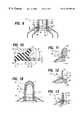
- FIG. 4is a perspective view, with portions broken away, of the inner tube of FIG. 1 .
- FIG. 5is a top plan view of the inner tube of FIG. 4 .
- FIG. 6is a side elevational view, with portions broken away, of the inner tube as would be seen along line 6 — 6 of FIG. 4 .
- FIG. 7is a front end elevational view, with portions broken away, of the inner tube, as would be seen along line 7 — 7 of FIG. 2 .
- FIG. 8is a vertical sectional view, with portions broken away, as would be seen along line 8 -S of FIG. 2 .
- FIG. 9is a vertical sectional view, with portions broken away, as would be seen along line 9 — 9 of FIG. 2 .
- FIG. 10is an enlarged view of the encircled portion shown in FIG. 3 .
- FIG. 11is a vertical sectional view, with portions broken away, of a portion of the outer tube positioned on injection mold tooling.
- FIG. 12is a vertical sectional view, with portions broken away, of the lower injection mold tooling being withdrawn from the outer tube of FIG. 11 .
- FIG. 13is a vertical sectional view, with portions broken away, of the inner tube inserted into and locked within the outer tube of FIG. 12 .
- FIG. 14is a vertical sectional view, with portions broken away, of an alternative embodiment of a dual dispense tube of the invention.
- FIG. 15is a vertical sectional view, with portions broken away, of another embodiment of a dual dispense tube of the invention.
- FIG. 16is a side elevational view, with portions broken away, showing an alternative embodiment of locking means of the inner tube of the dual dispense tube of the invention.
- FIG. 17is a side elevational view, with portions broken away, showing another embodiment of locking means of the inner tube of the dual dispense tube of the invention.
- FIG. 18is a vertical sectional view, with portions broken away, showing a method for removing the gates of assembled axially injection molded inner and outer tubes of the invention.
- FIGS. 1 and 2show a preferred embodiment of a dual dispense container of the invention. More particularly, FIGS. 1 and 2 show a collapsible dual dispense tube, generally designated 10 , comprised of an outer tube 12 and an inner tube 112 (dashed line) locked within the outer tube. Each tube 12 , 112 , is comprised of a tubular body wall 14 , 114 , respectively defining a portion of a first chamber 16 and of a second chamber 116 . Each tube 12 , 112 respectively additionally comprises a head, generally designated 18 , 118 , which in turn is comprised of a neck 22 , 122 , and a shoulder 20 , 120 to which the respective body wall 14 , 114 is joined.
- a headgenerally designated 18 , 118
- each neck 22 , 122has a dispense orifice 24 , 124 , the dispense orifices together defining main or combined, annular dual dispense orifice 0 of dual dispense tube 10 .
- each body wall 14 , 114is closed at its bottom by suitable means, as by interfolding and/or sealing the respective body wall to itself.
- the bottom of inner body wall 114is closed by being interfolded within and/or sealed within the seal of the bottom of outer body wall 14 .
- FIG. 3shows that outer tube neck 22 has a longitudinal axis LA, a base 26 , and a wall with an interior surface defining a cylindrical bore 28 which communicates with orifice 24 and chamber 16 .
- Bore 28is slightly tapered from a wider diameter at base 26 to a narrower diameter adjacent orifice 24 .
- Bore 28has a slight annular radially outward step 29 for assuring a liquid-tight seal between outer and inner tube necks 22 , 122 .
- Outer tube neck 22also includes securement means, here shown as preferably including a groove 30 at, including adjacent or proximate to, base 26 and extending from bore 28 into the interior surface of outer tube neck 22 .
- securement meanshere shown as preferably including a groove 30 at, including adjacent or proximate to, base 26 and extending from bore 28 into the interior surface of outer tube neck 22 .
- the securement means of outer tube neck base 26preferably also include an undersurface 32 , and an interstitial wall 34 between groove 30 and undersurface 32 and which forms part of outer tube neck bore 28 .
- a portion of undersurface 32communicates with outer tube chamber 16 and extends under a portion of the securement means, here, under groove 30 .
- the securement means of outer tube neck 22preferably includes latch 36 , which is comprised of a portion of neck base 26 and preferably is formed by a lower wall portion 31 (FIG. 10) of the lower wall which defines groove 30 , and by interstitial portion or wall 34 and a portion of base undersurface 32 .
- Base 26 of outer tube neck 22is the portion of the head at the junction of the vertical portion of neck 22 and the shoulder 20 .
- Base 26can include outer tube land 27 , and portions of the neck which are adjacent or proximate to the base, such as a short extent of the vertical portion of neck 22 , usually below the lowermost thread of a threaded neck.
- a portion neck 22 which is adjacent or proximate to base 26is below the mid-point of the axial extent of the neck.
- FIGS. 4 - 7show inner tube 112 . More particularly, FIGS. 4 - 7 show that inner tube neck 122 has a base 126 , and a wall with an interior surface defining a bore 128 which communicates with orifice 124 and chamber 116 .
- Inner tube 112has securement means, here shown as preferably including a bead 130 extending outward from the outer surface of the inner tube neck 122 , and being adapted to fit within and be frictionally engaged by groove 30 of outer tube neck 22 .
- FIGS. 4 - 7show that inner tube neck 122 has a base 126 , and a wall with an interior surface defining a bore 128 which communicates with orifice 124 and chamber 116 .
- Inner tube 112has securement means, here shown as preferably including a bead 130 extending outward from the outer surface of the inner tube neck 122 , and being adapted to fit within and be frictionally engaged by groove 30 of outer tube neck 22 .
- inner tube 112has locking means, here shown as a plurality of upstanding, preferably rigid, ribs 136 disposed about inner tube neck 122 and each having an abutment surface 137 which is adapted to abut a portion of undersurface 32 of outer tube neck base 26 , to thereby assist in securing inner tube 112 to outer tube 12 in a manner to be described.
- locking meanshere shown as a plurality of upstanding, preferably rigid, ribs 136 disposed about inner tube neck 122 and each having an abutment surface 137 which is adapted to abut a portion of undersurface 32 of outer tube neck base 26 , to thereby assist in securing inner tube 112 to outer tube 12 in a manner to be described.
- FIGS. 4 - 7also show that inner tube neck 122 is rectangular, and it has a rectangular orifice 124 and bore 128 , opposed elongated substantially straight side walls 138 , and opposed shorter arcuate end walls 140 .
- Inner tube neck 122is tapered from its narrow upper portion adjacent orifice 124 to its wider base portion adjacent base 126 and land 142 .
- the upper portion of each end wall 140extends about a shorter arc than the lower portion of each end wall.
- Each end wall 140is defined by opposed axial edges 144 which, at the upper portions of end walls 240 , directly adjoin with the respective upper portions of side walls 138 .
- Axial edges 144include circumferentially opposed outwardly projecting steps 146 , and circumferentially opposed extended axial edge portions 148 which define the wider, middle-to-lower and base portions of end walls 140 .
- the middle-to-lower and base portions of end walls 140adjoin each side wall 138 through an arcuate, axially extending side wall surface 150 .
- the wider middle-to-lower and base portions of end walls 140help provide lateral stability to the securement of inner tube 112 within outer tube 12 .
- FIG. 5shows that ribs 136 preferably are spaced equally, preferably 90°, from each other about the circumference of inner tube neck 122
- FIG. 7shows that the ribs communicate with and extend from inner tube neck 122 and with and from land 142 .
- FIGS. 8 - 10show the manner in which inner tube neck 122 is locked within outer tube neck 22 .
- FIG. 8a sectional view of dual dispense tube 10 as would be seen along line 8 — 8 of FIG. 2, shows inner tube 112 locked within outer tube 12 .
- FIG. 8is a vertical section through inner tube side walls 138 which shows, in front elevation, tube side wall surfaces 150 , and the cut edges of bead 130 frictionally engaged within outer tube neck groove 30 , and it shows portions of groove 30 which are not engaged with bead 130 .
- FIG. 8also shows upper surfaces 137 of inner tube ribs 136 in abutting engagement with a portion of outer tube neck base undersurface 32 which underlies groove 30 .
- FIG. 8shows that when a dual dispense tube 10 is squeezed, product A, contained in first chamber 16 between outer tube side wall 14 and inner tube side wall 114 , is moved upward between those side walls, between outer and inner tube shoulders 20 , 120 , to either side of and between and past ribs 136 , between inner tube side walls 138 and the juxtaposed portions of outer tube neck bore 28 , and out of a section or portion of outer tube orifice 24 of dual dispense tube orifice 0.
- product Bcontained in second chamber 116 within inner tube side wall 114 , is moved upward through bore 128 and directly out of inner tube orifice 124 , which is the central rectangular portion or section of dual dispense tube orifice 0.
- FIG. 9is a sectional view of dual dispense tube 10 of FIG. 2, taken along line 9 — 9 through inner tube end walls 140 , bead 130 and ribs 136 . More particularly, FIG. 9 shows inner tube neck 122 disposed and locked within outer tube neck 22 , wherein the outer surfaces of inner tube neck end walls 140 , including radially outwardly extending step wall 129 , are frictionally engaged with the juxtaposed portions of outer tube neck bore 28 . Bead 130 of each opposed end wall 140 is frictionally engaged with groove 30 in outer tube neck base 26 , and the portion of each end wall 140 directly below bead 130 is frictionally engaged with outer tube interstitial wall 34 .
- “Frictionally engaged”here preferably means that there is from a zero about a 0.002 (0.051 mm) or 0.003 inch (0.076 mm) tolerance or gap between the outer surface of inner tube end walls 140 , including bead 130 , and the inner surfaces of outer tube bore 28 , groove 30 and interstitial wall 34 .
- FIG. 9also shows that upper surfaces 137 of opposed inner tube ribs 136 abut a portion of outer tube neck base undersurface 32 which underlies bead 130 in groove 30 to thereby pinch and lock interstitial wall 34 firmly between rib upper surfaces 137 and bead 130 .
- the securement means of outer tube 12including groove 30 , interstitial wall 34 , latch 36 and undersurface 32 , and the securement means of inner tube 112 , including bead 130 and the locking means, comprised of ribs 136 , cooperate to lock inner tube 112 axially and laterally within outer tube 12 .
- inner tube neck 122can be locked within outer tube neck 22 by the aforesaid abutment and latching mechanism, without frictional engagement of an outer tube interstitial wall 34 with a juxtaposed portion of inner tube end wall 140 , and/or without pinching and locking of an interstitial wall.
- FIG. 10is an enlarged view with portions broken away of the encircled portion of FIG. 3 .
- FIG. 10shows that groove 30 extends in a direction radially outward from longitudinal axis LA of outer tube 12 (FIG. 3) and into the outer tube neck interior surface which forms bore 28 .
- FIG. 10shows that groove 30 has, and is defined in part by, a lower wall portion 31 which also forms the upper portion of latch 36 .
- Latch 36is here shown in the form of a lip, and is formed by a portion of outer tube neck base 26 , lower wall portion 31 , interstitial wall 34 and a portion of outer tube neck base undersurface 32 .
- interstitial wall 34forms part of bore 28 and is located between the lower edge defining groove 30 and the radially inward edge of undersurface 32 .
- the radially inward edgeis chamfered.
- groove 30has an axial height H
- interstitial wall 34 of latch 36has an axial height h.
- height hcan equal or approximately equal height H.
- interstitial wall axial height his less than groove axial height H, more preferably it is less than 1 ⁇ 2, and most preferably it is about 1 ⁇ 4 to about 1 ⁇ 3 of groove axial height h.
- outer and inner tube necks 22 , 122are made of a polyethylene material such as a high density polyethylene
- inner tube neck 122can be locked firmly within outer tube neck 22 by employing an outer tube groove 30 having an axial height H of about 0.064 inch (1.626 mm) and an outer tube interstitial wall 34 whose axial height h is about 0.019 inch (0.483 mm).
- These heights, particularly axial height hcan vary depending on the polymeric materials employed and their physical characteristics, particularly their flexibility.
- axial height hcould equal or possibly even exceed axial height H.
- the axial height hmay be less than 1 ⁇ 4 of groove axial H.
- FIG. 10shows that groove 30 preferably is formed in part by two curved surfaces, an upper curved surface formed by a radius R, and a lower curved surface formed by a radius r.
- radius ris shorter than radius R.
- the outer surface of convexly shaped bead 130is formed with basically the same radii as employed for groove 30 .
- the greater radius B of the upper curved surface of bead 130allows bead 130 to slip easily past interstitial wall 34 if these surfaces come into contact during assembly of dual dispense tube 10 , when inner tube neck 122 is pushed up into outer tube neck 12 .
- inner tube neck and outer tube neckare adapted such that when bead 130 is seated within groove 30 , ribs 136 abut a portion of outer tube neck undersurface 32 . Inner tube 112 is thereby prevented from being inserted further into outer tube 12 , without need of any aforementioned problematical prior art radially inwardly directed flange at the orifice of outer tube orifice 24 .
- groove 30includes an upper curved surface radius B of about 0.040 inch (1.016 mm), a lower curved surface radius r of about 0.015 inch (0.381 mm), a groove radial depth and consequently a latch radial length L of about 0.018 inch (0.457 mm).
- the interstitial wall axial height his about 0.019 inch (0.483 mm).
- the chamfered edge adjoining undersurface 32 and interstitial wall 34can be formed by a radius of about 0.005 inch (0.127 mm).
- the physical and other characteristics and dimensions of base 26 and/or of latch 36are chosen and/or adapted to enable latch 36 to flex and deflect downward and radially outward when outer tube neck 22 is disassociated from the injection mold tooling on which the neck is formed, and to be forced radially inward and upward by locking means to latch, entrap and lock bead 130 in groove 30 .
- some flexibility and deflection of latch 36can be obtained by design of some flexibility in or some flexing of inner tube neck base connecting wall 33 , most of the flexing or deflection is of latch 36 itself.
- FIGS. 11 and 12show apparatus for forming head 18 of outer tube 12 . More particularly, FIG. 11 shows head 18 of outer tube 12 formed on male injection molding tooling comprised of an upper tool 152 , and a lower tool 154 having an outwardly extending bead 156 forming groove 30 in bore 28 of outer tube neck 22 .
- outer tube head 18As shown in FIG. 12, once outer tube head 18 is formed, the head and tooling are separated from one another. For example, head 18 can be held stationary while upper tool 152 (FIG. 11) is withdrawn axially upward (not shown) and lower tool 154 is withdrawn axially downward from outer tube neck 22 . As lower tool 154 is being withdrawn, bead 156 of lower tool 154 engages groove lower wall 31 and causes latch 36 to deflect and pivot radially outward and downward. Outer tube neck base 26 may also be deflected outward.
- head 18 of outer tube 12 , and head 118 of inner tube 122can be formed by any suitable method, for example by injection or compression molding, and that each head can be assembled or secured to a tubular body wall by any suitable method, for example, with heat by induction to weld the head to the body wall.
- Axial downward movement of inner tube 112 relative to outer tube 12is prevented by the frictional engagement and entrapment of bead 130 in groove 30 , particularly at groove lower wall 31 which wall is immobilized by latch 36 being pinched, held and locked primarily between bead 130 and ribs 136 , and preferably also by interstitial wall 34 being frictionally engaged with the juxtaposed portion of end wall 140 .
- Lateral movement of inner tube 112 within outer tube 12is prevented by one or more of a number of features, including mainly that upper surfaces 137 of inner tube ribs 136 directly abut against outer tube neck base undersurface 32 .
- the surface portions of ribs 136 and of undersurface 32 which abut each otherpreferably are in the same or corresponding planes, which planes preferably are parallel and at an angle which is equal to or less than 90° relative to the longitudinal central axis LA of outer tube neck 22 .
- the planescan be at an angle greater than 90°.
- the abutting surfaces portions of ribs 136 and of undersurface 32abut along a length or extent sufficient to provide lateral stability of inner tube 112 within outer tube 12 .
- the plurality of at least three, preferably four, ribs 136are spaced from each other about inner tube neck 122 a sufficient, preferably equal, distance to prevent inner tube 112 from rocking or moving laterally within outer tube neck 22 .
- the lower portions of inner tube end walls 140are broader than their upper portions, and the lower portions of end walls 140 and bead 130 extend through an arc which is greater than 180° about inner tube neck 122 .
- FIG. 14shows an alternative embodiment of the dual dispense container of this invention. More particularly, FIG. 14 shows a dual dispense tube 10 ′ whose outer tube neck 22 ′, has means in the form of a radially inwardly extending bead 130 ′, an undersurface 32 ′ and an interstitial wall 34 ′ between bead 130 ′ and undersurface 32 ′.
- Inner tube neck 122 ′has securement means in the form of a radially inwardly extending groove 30 ′ in the exterior surface of inner tube end wall 140 ′, ribs 136 having an upper surface 137 , and a radially outwardly extending step 141 ′ between groove 30 ′ and undersurface 32 ′.
- FIG. 15shows an alternative embodiment of the dual dispense container of this invention. More particularly, FIG. 15 shows a dual dispense tube 10 ′′ whose outer tube neck 22 ′′ has at its base 26 ′′, securement means in the form of a radially inwardly extending bead 130 ′′, and an undersurface 32 ′′.
- Inner tube neck 122 ′′has securement means in the form of a radially inwardly extending groove 30 ′′ in the exterior surface of inner tube end wall 140 ′, and ribs 136 having an upper surface 137 .
- FIG. 15shows that it is within the scope of this invention that an inner tube neck can be locked within an outer tube neck without a latching mechanism or an interstitial wall.
- ribs 136rigidify and stabilize inner tube necks 122 ′, 122 ′′ against radially inward movement.
- FIG. 16shows an inner tube 112 ′′′ having the same elements as inner tube 112 except that, here, the locking means are in the form of a plurality of members, e.g. arms 136 ′ or pins which are integral with and extend radially outward from end walls 140 . Arms 136 ′ are not supported by or connected to inner tube land 142 .
- FIG. 17shows an inner tube 112 ′′′′ having the same elements as inner tube 112 except that, here, the locking means are in the form of pillars 136 ′′ which are integral with and supported by land 142 , but are not connected to inner tube end wall 140 ′. Also, inner tube end wall 140 ′ has indentations 158 therein (one shown by dashed lines) each of which is radially aligned with and in which resides the radially inner side edge 160 of rib 136 ′′.
- FIGS. 1 through 17show that improved securement of an inner container within an outer container can be obtained for a dual dispense container by providing the securement means at, including adjacent or proximate, the base of the outer tube neck, and preferably also at, including adjacent or proximate, the base of or a lower portion of the inner tube neck, which securement means at those locations, are relatively more stable than they would be at other locations of the tube necks.
- main features of the invention for providing the lack of movement, stability and lockare the aforementioned locations of the securement means, and the abutment of the locking means, e.g. ribs, 136 , of inner tube 112 directly against a portion of undersurface 32 , 32 ′, 32 ′′ of outer tube neck base 26 , 26 ′, 26 ′′.
- the dual dispense tube of the inventionis advantageous for several reasons.
- latch 36flexes radially outward and downward, and shoulder 20 may flex slightly outward.
- the male toolcan be removed with little or no shearing of latch 36 or its interstitial wall 34 .
- the short axial travel distance of beaded inner tube 112 along the toolingminimizes or eliminates shearing of bead 130 .
- inner tube neck 122 with bead 130can be moved past latch 36 and inserted into outer tube neck 22 typically with slight (or possibly with no) contact between bead 130 and latch 36 and thus with no shearing of bead 130 . Shearing and extensive contact of bead 130 with the surface of bore 28 is avoided also because bead 130 need only travel a short axial distance into or near outer tube neck base 26 to reach and seat in groove 30 .
- Avoidance of a long axial travel of bead 130 into upper portions of the outer tube neckalso avoids possible outward distortion of outer tube neck 12 , inward compression and distortion of inner tube neck 112 , and the consequent possible problems of leakage and loose bead/groove engagement.
- the provision of abutment surfaces 137 of ribs 136 directly or nearly directly below bead 130provides, preferably along extended surfaces, an immediate, full stop of axial travel of inner tube neck 122 up into outer tube neck 22 . This avoids over-insertion of inner tube 112 into outer tube 12 , and displacement of the bead from the groove during product filling of tube chambers 16 , 116 .
- land 142is about 0.020 inch high (0.508 mm)
- ribs 136are about 0.125 inch (3.175 mm) high and about 0.040 inch (1.016 mm) wide.
- the axial height of the gap between rib upper surfaces 137 and the junction of side wall 140 with bead 130is about 0.028 inch (0.711 mm).
- Assembled dual dispense containers employing the securement system of the invention and therefore having an inner tube locked axially and also laterally within an outer tubeare advantageous because the tube necks can be provided with a dual dispense orifice in one plane and having a uniform rim seal surface. As shown in FIG.
- inner and outer tube heads 18 , 112can be made separately by an axial injection molding process, and the resulting inner and outer tubes 12 , 112 , each having a gate G, g, closing the orifice of its neck, can be assembled, secured together in accordance with the invention, and have their gates G, g simultaneously removed by a suitably operated cutting means, e.g., by blade B in one snipping, cutting, or trimming operation.
- a suitably operated cutting meanse.g., by blade B in one snipping, cutting, or trimming operation.
- thisprovides an assembled dual dispense tube whose orifices, that is, whose rims or upper edges of outer and inner tube orifices 24 , 124 are in the same plane, and thereby have a uniform seal surface.
- the orifices of the outer and inner tubesare surface.
- the orifices of the outer and inner tubesare considered to be in the same plane and provide a uniform seal surface if they are within a range of from about 0 to about 0.003 inch (0.076 mm). Simultaneously removing the gates of the assembled dual dispense tube minimizes variations in the axial lengths of the tube necks and thereby minimizes possibilities of leakage and premature mixing of contained products.
- One methodis to trim and remove gate G of outer tube neck, insert the untrimmed inner tube neck into the outer tube neck, using untrimmed gate of the inner tube to orient and facilitate placement of the inner tube neck within the outer tube neck, trim and remove inner tube gate g, and cap the outer tube neck.
- a capis preferred and advantageous because it helps to prevent lateral movement or canting of the inner tube within the outer tube, especially if the fit of the inner tube neck within the outer tube neck and the bead/groove interlock are not sufficient to prevent canting.
- latch 36An important feature of this invention is the flexibility or deflectability of latch 36 .
- thispreferably is provided primarily by the design, and selection of the characteristics and dimensions of latch 36 itself, and secondarily, if at all, of adjacent portions of base portion 26 of outer tube neck 22 .
- latch 36preferably is primarily designed to flex, deflect, pivot or be displaced radially outward and downward from or about what can be considered a hinge point adjacent a curved portion of lower wall 31 of groove 30 , and secondarily, to a lesser extent, if at all, from or about neck base connecting wall portion 33 (FIG. 10 ).
- base wall connecting portion 33is annular, is tapered radially inwardly and upwardly, and has concave outer and inner surfaces which form a thinned region therebetween which may provide an area for minor movement or displacement of outer tube neck base 26 and therefore of latch 36 .
- latch 36need not be an integral or singular member.
- itcan be split, for example by a horizontal radially outwardly extending cut or its function can be provided by separate cooperative members.
- latch 36need not be or have a surface which is contiguous with lower wall surface 31 of groove 30 .
- interstitial wall 34need not be an annular or axial surface. It can have any suitable configuration, shape, or dimension.
- interstitial wall 34need not frictionally engage the juxtaposed portion of end wall 140 which is below bead 130 , and it need not form part of or be aligned with slightly tapered (about 30) outer tube neck bore 28 .
- latch 36can be a radially short member such that it extends under only a portion of groove 30 or bead 130 , so long as when abutted, it functions as a latch to hold and lock bead 130 in groove 30 .
- outer tube neck base undersurface 32need not be part of latch 36 .
- the portion of undersurface 32 which is abutted by ribs 136can be a single surface in one plane, or several surfaces in several planes, and it or they can be of any suitable shape, dimension, or configuration, e.g. angled, undulating, stepped, etc.
- the same applies to the abutting upper surface(s) 137 of ribs 136so long as the abutment of upper surface(s) 137 against undersurface(s) 32 cause(s) the latching and locking of bead 130 or of a similar functioning protruding member or members of inner tube neck 122 .
- latch 36Although three or more preferably equally spaced ribs can be employed, four equally spaced ribs are preferred as they render latch 36 effective in preventing canting of inner tube 112 and in abutting and latching latch 36 , while also providing a minimum of interference of only one thin rib in each product A flow passageway between bore 28 and inner tube side wall 138 .
- outer tube groove 30preferably is annular and continuous about outer tube bore 28 , as this permits the use of a discontinuous bead 130 or protrusion and obviates need for orientation between the bead or protrusion and groove.
- the bead or protrusionis provided at the base of the outer tube neck, and the groove is provided in the outer surface of the inner tube neck, it is preferred that each be discontinuous and oriented so to avoid interference with the wall surfaces which define the flow passageways for product A from chamber 16 to orifices 24 .
- the groove/bead or protrusion interlocking or similar functioning memberscan cover any suitable circumferential distance about the inner tube neck, preferably they cover a total of at least 180° thereabout, so as to provide stability to the securement and to prevent rocking of the inner tube neck within the outer tube neck.
- bead 130 and groove 30can be annular and continuous, such is not preferred because it requires complicated designs and manufacturing equipment to create passageways for flow of product A contained in outer tube 12 radially inwardly or outwardly of the continuous annular bead and groove.
- the bead and groovecan be of any suitable shape, size or configuration.
- the beadcan have a downwardly sloping upper wall, a vertical side wall and a horizontal bottom wall.
- the dual dispense container of this inventioncan be made of any material(s) suitable for making such containers. Such materials are known to persons skilled in the art.
- the tubular bodies of the containerscan be made of metal(s), plastic(s) or combinations of the same.
- the heads of the containerscan be made of any suitable material, preferably one which will provide an operative, movable, preferably flexible latch according to the invention.
- Preferred materialsinclude thermoplastics, such as ethylene polymers, including high and medium density polyethylenes, ethylene copolymers, propylene polymers, including polypropylene, propylene copolymers, and blends and ethylene and propylene polymers and copolymers.
- the dual dispense container of this inventioncan be made by methods and tooling known to those skilled in the art.
- a tubular bodycan be formed by extrusion of a single layer of plastic material for forming a single layer plastic tube, or by lamination or coextrusion of a multiple layer film which is formed into a tubular body.
- the tubular bodycan be placed on appropriate tooling and a head, for example, a pre-formed compression or injection molded head, can be joined to the tubular body.
- the tubular bodycan be placed in injection mold tooling wherein a tube head is axially injection molded and thermally joined at its shoulder to the tubular body.
- the procedurescan be employed to separately form inner tube 12 and outer tube 112 of the invention.
- the tube headsare injection molded with tooling adapted to provide the securement means of the invention at the preferred locations as described above.
- injection mold toolingwhich forms the groove in the outer tube neck base and which is withdrawn axially downward from the outer tube neck, the latch is moved or is pivoted radially outward to an open latch position.
- the dual dispense tubeis assembled by inserting the inner tube neck within the outer tube neck with the bead of the inner tube neck passing axially by and without contacting or slightly contacting but not shearing the open latch of the outer tube neck.
- the inner tube neckis inserted into the outer tube neck until the bead is seated in the groove of the latter and the locking means of the former abut the undersurface of the outer tube neck base. This moves the latch radially upward and inward and latches and locks the bead of the inner tube within the groove of the outer tube.
- the gates of the orifices of the heads of the assembled axially injection molded inner and outer tubescan be simultaneously cut or trimmed by suitable means and removed in one operation to provide resulting orifices of the inner and outer tubes in the same plane, and thereby provide the dual dispense tube with a uniform seal surface.
- the assembled tubeis then capped using conventional capping methods. After the inner tube and outer tube are simultaneously or serially conventionally filled with product, the open bottom ends of the tubes are conventional sealed individually or together.
- the securement system of this inventionis not limited to being employed in connection with any particular design or configuration of multiple product or other dispensing orifice, or with any particular design or configuration of dual dispense container, meaning and including a multiple product, or multiple effect, dispensing container.
- the securement systemcan be employed to hold and lock an inner container, or any inner member, structure or insert at, adjacent or proximate, to or in the base of an outer container neck.
- the securement systemcan be employed in connection with a dual tube whose inner tube neck is short and does not extend fully to the orifice of the outer tube, such that the contained products are finally dispensed from only the orifice of the outer tube.
- the securement systemalso can be employed in connection with an outer tube that does not have an inner tube, but only has an insert attached at the base of the outer tube neck, for example, for segregating flow or providing a striping or other effect to one or more products, or for providing barrier properties to the outer tube head.
- the preferred dual dispense tube 10 of this inventionconfigured as described herein and having a rectangular inner tube orifice 124 positioned or sandwiched between the opposed sections of outer tube orifice 24 , is employed for packaging products which have dissimilar flow characteristics. More particularly, dual dispense tube 10 with its sandwich-type dual dispense orifice and passageways is designed to dispense a product A, contained in the outer tube and having, for example, a lower viscosity, through outer tube channels and orifices which present more surface resistance and impart a greater pressure drop, together with a product B, contained in the inner tube and having, for example, a higher viscosity, through bore 128 which presents relatively less flow resistance and pressure drop.
Landscapes
- Engineering & Computer Science (AREA)
- Mechanical Engineering (AREA)
- Containers And Packaging Bodies Having A Special Means To Remove Contents (AREA)
- Tubes (AREA)
- Closures For Containers (AREA)
- Details Of Rigid Or Semi-Rigid Containers (AREA)
- Packages (AREA)
Abstract
Description
Claims (27)
Priority Applications (18)
| Application Number | Priority Date | Filing Date | Title |
|---|---|---|---|
| US09/295,824US6176395B1 (en) | 1999-04-21 | 1999-04-21 | Dual dispense container |
| PCT/US2000/009770WO2000063112A1 (en) | 1999-04-21 | 2000-04-12 | Dual dispense container |
| DE60025598TDE60025598T2 (en) | 1999-04-21 | 2000-04-12 | TWO CHAMBER SUPPLY VESSEL |
| AU42344/00AAU756538B2 (en) | 1999-04-21 | 2000-04-12 | Dual dispense container |
| CZ20013755ACZ20013755A3 (en) | 1999-04-21 | 2000-04-12 | Dual dispense container and a method for locking thereof |
| CA2370732ACA2370732C (en) | 1999-04-21 | 2000-04-12 | Dual dispense container |
| MXPA01009944AMXPA01009944A (en) | 1999-04-21 | 2000-04-12 | Dual dispense container. |
| ES00922108TES2260008T3 (en) | 1999-04-21 | 2000-04-12 | DOUBLE DOSAGE CONTAINER. |
| JP2000612213AJP3966692B2 (en) | 1999-04-21 | 2000-04-12 | Double supply container |
| CNB008064555ACN1247440C (en) | 1999-04-21 | 2000-04-12 | Dual dispense container |
| PT00922108TPT1194367E (en) | 1999-04-21 | 2000-04-12 | DOUBLE DISPENSING CONTAINER |
| BRPI0009849-3ABR0009849B1 (en) | 1999-04-21 | 2000-04-12 | double dispense container, contractile double dispense tube, and methods for locking an inner dispense tube into an outer dispense tube to form a mounted double dispense tube, and to form a double dispense tube. |
| EP00922108AEP1194367B1 (en) | 1999-04-21 | 2000-04-12 | Dual dispense container |
| PL00350316APL193626B1 (en) | 1999-04-21 | 2000-04-12 | Dual dispense container |
| AT00922108TATE316066T1 (en) | 1999-04-21 | 2000-04-12 | TWO-CHAMBER DISPENSING CONTAINER |
| RU2001131358/12ARU2224700C2 (en) | 1999-04-21 | 2000-04-12 | Double dispensing container (variants), method of container securing into outer dispensing container and method for container production |
| ARP000101837AAR035840A1 (en) | 1999-04-21 | 2000-04-19 | DUAL DISPENSER CONTAINER, COLLAPSABLE DUAL DISPENSER TUBE, SAME CLOSURE METHOD AND METHOD FOR FORMING SUCH DUAL DISPENSER TUBE |
| MYPI20001665AMY124019A (en) | 1999-04-21 | 2000-04-19 | Dual dispense container. |
Applications Claiming Priority (1)
| Application Number | Priority Date | Filing Date | Title |
|---|---|---|---|
| US09/295,824US6176395B1 (en) | 1999-04-21 | 1999-04-21 | Dual dispense container |
Publications (1)
| Publication Number | Publication Date |
|---|---|
| US6176395B1true US6176395B1 (en) | 2001-01-23 |
Family
ID=23139377
Family Applications (1)
| Application Number | Title | Priority Date | Filing Date |
|---|---|---|---|
| US09/295,824Expired - LifetimeUS6176395B1 (en) | 1999-04-21 | 1999-04-21 | Dual dispense container |
Country Status (18)
| Country | Link |
|---|---|
| US (1) | US6176395B1 (en) |
| EP (1) | EP1194367B1 (en) |
| JP (1) | JP3966692B2 (en) |
| CN (1) | CN1247440C (en) |
| AR (1) | AR035840A1 (en) |
| AT (1) | ATE316066T1 (en) |
| AU (1) | AU756538B2 (en) |
| BR (1) | BR0009849B1 (en) |
| CA (1) | CA2370732C (en) |
| CZ (1) | CZ20013755A3 (en) |
| DE (1) | DE60025598T2 (en) |
| ES (1) | ES2260008T3 (en) |
| MX (1) | MXPA01009944A (en) |
| MY (1) | MY124019A (en) |
| PL (1) | PL193626B1 (en) |
| PT (1) | PT1194367E (en) |
| RU (1) | RU2224700C2 (en) |
| WO (1) | WO2000063112A1 (en) |
Cited By (55)
| Publication number | Priority date | Publication date | Assignee | Title |
|---|---|---|---|---|
| US20010053334A1 (en)* | 2000-02-22 | 2001-12-20 | Shiping Chen | Microarray fabrication techniques and apparatus |
| US6347726B1 (en)* | 1999-04-21 | 2002-02-19 | Pechiney Plastic Packaging, Inc. | Dual dispense container having cloverleaf orifice |
| US6460733B2 (en)* | 2001-02-20 | 2002-10-08 | Mti Microfuel Cells, Inc. | Multiple-walled fuel container and delivery system |
| US6615883B2 (en) | 2001-12-07 | 2003-09-09 | Pechiney Plastic Packagaing, Inc. | Container having splines and method for using same |
| US6662530B1 (en)* | 2000-11-16 | 2003-12-16 | Colgate-Palmolive Company | Method of making dual chamber sachet |
| US20040007594A1 (en)* | 2002-07-09 | 2004-01-15 | Esch Willy Van | Bonus flavor dispenser |
| US20040057920A1 (en)* | 2002-09-20 | 2004-03-25 | The Procter & Gamble Company | Striped liquid personal cleansing compositions containing a cleansing phase and a seperate benefit phase |
| US20040074860A1 (en)* | 2002-08-21 | 2004-04-22 | L'oreal | Receptacle having a reinforced wall |
| US20040092415A1 (en)* | 2002-11-04 | 2004-05-13 | The Procter & Gamble Company | Striped liquid personal cleansing compositions containing a cleansing phase and a separate benefit phase with improved stability |
| US20040159678A1 (en)* | 2002-03-12 | 2004-08-19 | Chemque, Incorporated | Apparatus and method for mixing and dispensing components of a composition |
| US20040223991A1 (en)* | 2003-05-08 | 2004-11-11 | The Procter & Gamble Company | Multi-phase personal care composition |
| US20040235693A1 (en)* | 2003-05-01 | 2004-11-25 | The Procter & Gamble Company | Striped liquid personal cleansing compositions containing a cleansing phase and a separate benefit phase comprising a high internal phase emulsion |
| US20050143268A1 (en)* | 2003-11-14 | 2005-06-30 | The Procter & Gamble Company | Personal care composition containing a cleansing phase and a benefit phase |
| US20050143269A1 (en)* | 2003-12-24 | 2005-06-30 | Wei Karl S. | Multi-phase personal cleansing compositions comprising a lathering cleansing phase and a non-lathering structured aqueous phase |
| US20050192187A1 (en)* | 2004-02-27 | 2005-09-01 | Wagner Julie A. | Mild multi-phased personal care composition |
| US20050192189A1 (en)* | 2004-02-27 | 2005-09-01 | Wagner Julie A. | Mild body wash |
| US20050192188A1 (en)* | 2004-02-27 | 2005-09-01 | Wagner Julie A. | Mild body wash |
| US20050276768A1 (en)* | 2004-06-14 | 2005-12-15 | Karl Shiqing Wei | Multi-phased personal care composition |
| US20060008438A1 (en)* | 2004-07-09 | 2006-01-12 | Velarde Andres E | Multi-phased personal care composition |
| US20060079420A1 (en)* | 2004-10-08 | 2006-04-13 | Wagner Julie A | Multi-phase personal cleansing composition |
| US20060094628A1 (en)* | 2003-12-24 | 2006-05-04 | Wei Karl S | Multi-phase personal cleansing compositions comprising a lathering cleansing phase and a non-lathering structured aqueous phase |
| US20060102581A1 (en)* | 2004-11-15 | 2006-05-18 | Yates William M Iii | Multiple chamber bottle and method of filling and assembling same |
| US20060191589A1 (en)* | 2005-02-25 | 2006-08-31 | Mccall Patrick C | Multi-phase personal care compositions, processes for making and providing, and articles of commerce |
| US20060198686A1 (en)* | 2005-03-04 | 2006-09-07 | Cosmolab Inc. | Multi-reservoir container with applicator tip and method of making the same |
| US20060210505A1 (en)* | 2005-03-21 | 2006-09-21 | Clapp Mannie L | Multi-phase personal care composition comprising visually distinct phases |
| US20060252662A1 (en)* | 2005-04-13 | 2006-11-09 | Soffin Daniel J | Mild, structured, multiphase personal cleansing compositions comprising density modifiers |
| US20070072781A1 (en)* | 2005-04-13 | 2007-03-29 | Soffin Daniel J | Mild, structured, multi-phase personal cleansing compositions comprising density modifiers |
| US20070095702A1 (en)* | 2004-02-24 | 2007-05-03 | Theodor Park | Multi-chamber tube package |
| US20070137042A1 (en)* | 2005-12-20 | 2007-06-21 | Focht Heather L | Shaving kit, article of commerce and a method of shaving comprising a personal care composition |
| US20070141001A1 (en)* | 2005-12-15 | 2007-06-21 | The Procter & Gamble Company | Non-migrating colorants in multi-phase personal cleansing compositions |
| US20070167338A1 (en)* | 2006-01-09 | 2007-07-19 | Mchugh Colin M | Multiphase personal care compositions comprising beads |
| US20070163990A1 (en)* | 2005-12-08 | 2007-07-19 | Roberto Escobosa | Container comprising an in-mold label positioned proximate to a surface topography |
| US20070187429A1 (en)* | 2006-02-15 | 2007-08-16 | Bardia Farahmand | Dual opening tubular dispenser |
| US20070199955A1 (en)* | 2006-02-27 | 2007-08-30 | Stalions Stephen E | Dispensing container for two flowable products |
| US20070199953A1 (en)* | 2006-02-27 | 2007-08-30 | Laveault Richard A | Dispensing container for two flowable products |
| US20070199954A1 (en)* | 2006-02-27 | 2007-08-30 | Law Brian R | Dispensing container for two flowable products |
| US20070248562A1 (en)* | 2006-02-28 | 2007-10-25 | The Procter & Gamble Company | Stable multiphase composition comprising alkylamphoacetate |
| US20070280976A1 (en)* | 2005-06-07 | 2007-12-06 | The Procter & Gamble Company | Multi-phased personal care composition comprising a blooming perfume composition |
| US20080121653A1 (en)* | 2005-05-30 | 2008-05-29 | Cebal Sas | Sealing Condition of Multiple-Container, in Particular Double-Tube, Packages Designed for Instant Preparation |
| US20080242573A1 (en)* | 2007-03-30 | 2008-10-02 | Karl Shiqing Wei | Multiphase personal care composition comprising a structuring system that comprises an associative polymer, a low hlb emulsifier and an electrolyte |
| US20090028809A1 (en)* | 2007-07-27 | 2009-01-29 | Jonathan Robert Cetti | Personal care article for sequentially dispensing compositions with variable concentrations of hydrophobic benefit materials |
| US20090028808A1 (en)* | 2007-07-27 | 2009-01-29 | The Procter & Gamble Company | Personal care article for sequentially dispensing compositions with variable concentrations of partitioned benefit or suspended benefit agents |
| US20090029900A1 (en)* | 2007-07-27 | 2009-01-29 | The Procter & Gamble Company | Personal care article for sequentially dispensing compositions with distinct fragrance characters |
| US20090026222A1 (en)* | 2005-11-08 | 2009-01-29 | Belcap Switzerland Ag | Container Closure for Simultaneously Pouring Out Two Separate Liquids With a Specified Quantitative Ratio |
| US7531497B2 (en) | 2004-10-08 | 2009-05-12 | The Procter & Gamble Company | Personal care composition containing a cleansing phase and a benefit phase |
| US20090152294A1 (en)* | 2007-12-12 | 2009-06-18 | Mizell Jeffrey W | Dual-Tube Product Container and Dispenser |
| US20090324520A1 (en)* | 2007-07-27 | 2009-12-31 | Jonathan Robert Cetti | Personal-care article for sequentially dispensing compositions with variable concentrations of partitioned benefit or suspended benefit agents |
| US7666825B2 (en) | 2004-10-08 | 2010-02-23 | The Procter & Gamble Company | Stable, patterned multi-phased personal care composition |
| WO2011003048A1 (en)* | 2009-07-01 | 2011-01-06 | Fadi Kalaouze | Multi-compartment beverage container |
| US20110117225A1 (en)* | 2007-03-30 | 2011-05-19 | Karl Shiqing Wei | Multiphase personal care composition comprising a structuring system that comprises an associative polymer, a low hlb emulsifier and an electrolyte |
| US20110127296A1 (en)* | 2009-11-30 | 2011-06-02 | Jeffrey Marc Hayet | Apparatus for simultaneously dispensing two products |
| US8104616B2 (en) | 2006-02-11 | 2012-01-31 | The Procter & Gamble Company | Clamshell package for holding and displaying consumer products |
| US8413845B1 (en) | 2009-07-20 | 2013-04-09 | Thomas J. Duncan | Dual-compartment dispensing container |
| US9114087B2 (en) | 2003-05-01 | 2015-08-25 | The Procter & Gamble Company | Process for making visually distinctive multiple liquid phase compositions |
| CN114162452A (en)* | 2020-09-10 | 2022-03-11 | 株式会社三和 | Container for spraying liquid |
Families Citing this family (7)
| Publication number | Priority date | Publication date | Assignee | Title |
|---|---|---|---|---|
| RU2408458C2 (en)* | 2006-06-27 | 2011-01-10 | АйДиЭм Уорлд, С.Л. | Device for moulding, filling and closing foamed-polymer containers |
| NL1034895C2 (en)* | 2008-01-08 | 2009-07-13 | Dispensing Technologies Bv | Composite container and method for manufacturing thereof. |
| IT1398945B1 (en)* | 2010-03-17 | 2013-03-28 | Lumson Spa | METHOD FOR THE REALIZATION OF A CONTAINER TO BE USED WITH A HERMETIC PUMP. |
| JP5972306B2 (en)* | 2014-04-10 | 2016-08-17 | 株式会社セレス | Tube container |
| KR102190119B1 (en)* | 2020-06-16 | 2020-12-11 | 차수현 | Double tube container for separate cleaning and hand cream |
| KR102231360B1 (en)* | 2020-09-10 | 2021-03-25 | 차수현 | Double tube container for separate cleaning and hand cream |
| KR102443577B1 (en)* | 2020-09-11 | 2022-09-15 | 주식회사 대일물산 | hand shower cleaner |
Citations (41)
| Publication number | Priority date | Publication date | Assignee | Title |
|---|---|---|---|---|
| FR577523A (en) | 1924-02-21 | 1924-09-06 | Dentifrices Bi Oxyne | Tubes for pasty, viscous or other products |
| US1535529A (en) | 1921-06-11 | 1925-04-28 | Hopkins Nevil Monroe | Collapsible tube |
| US1555676A (en) | 1922-08-18 | 1925-09-29 | John T Leland | Collapsible tube |
| US1639699A (en) | 1923-08-29 | 1927-08-23 | Gilmont Products Corp | Article of manufacture comprising container and contents therefor |
| US1698404A (en) | 1923-10-16 | 1929-01-08 | Gilmont Products Corp | Ultiple-compartment collapsible tube |
| US1699532A (en) | 1924-07-11 | 1929-01-22 | Gilmont Products Gorporation | Multiple collapsible tube |
| US2218092A (en) | 1939-10-06 | 1940-10-15 | Squibb & Sons Inc | Container |
| US2918199A (en) | 1957-02-25 | 1959-12-22 | John J Spero | Method of dispensing paste-like material |
| US2939610A (en) | 1957-10-03 | 1960-06-07 | Johnson & Johnson | Dispensing device |
| US3007614A (en) | 1958-04-28 | 1961-11-07 | Fred A Morrow | Dispenser closure |
| US3042263A (en) | 1959-11-13 | 1962-07-03 | Sr John Gallo | Striped paste dispenser |
| GB956377A (en) | 1959-12-30 | 1964-04-29 | Unilever Ltd | Improvements in or relating to devices for dispensing paste-like materials |
| US3135428A (en) | 1963-02-18 | 1964-06-02 | Gallo John | Dispensing device |
| US3168968A (en) | 1963-01-11 | 1965-02-09 | Hans Schwarzkopf | Elastically deformable container |
| US3175731A (en) | 1963-02-28 | 1965-03-30 | Irving A Ellman | Fluoride-containing dentifrice dispenser |
| US3200995A (en) | 1962-08-30 | 1965-08-17 | Colgate Palmolive Co | Multicompartment dispensing package |
| US3206074A (en) | 1962-09-18 | 1965-09-14 | Colgate Palmolive Co | Multiple compartmented dispensing package |
| US3217931A (en) | 1962-07-31 | 1965-11-16 | Colgate Palmolive Co | Multicompartment dispensing of different fluent materials |
| US3335912A (en) | 1966-11-02 | 1967-08-15 | Colgate Palmolive Co | Collapsible compartmented dispensing container |
| US3506157A (en) | 1968-12-11 | 1970-04-14 | Joseph Dukess | Pronged closure device for multiple compartment squeeze tube |
| US3724722A (en) | 1971-06-03 | 1973-04-03 | F Ballo | Container construction |
| GB1385924A (en) | 1972-11-10 | 1975-03-05 | Ump Venesta Ltd | Packaging tubes |
| US3876111A (en) | 1972-04-20 | 1975-04-08 | Cambridge Res & Dev Group | Plural chambered squeeze tube |
| US3936334A (en) | 1971-12-25 | 1976-02-03 | Yoshino Kogyosho Co., Ltd. | Collapsable tube |
| US4148416A (en) | 1976-08-20 | 1979-04-10 | Metal Box Limited | Aerosol containers |
| US4211341A (en) | 1976-08-16 | 1980-07-08 | Colgate-Palmolive Company | Dispensing container of stabilized extrudable dentifrice containing normally chemically reactive components |
| US4528180A (en) | 1983-03-01 | 1985-07-09 | Schaeffer Hans A | Dental preparation, article and method for storage and delivery thereof |
| JPS60188150A (en) | 1984-03-06 | 1985-09-25 | 株式会社トプコン | Ophthalmological phototherapy device |
| US4585149A (en) | 1982-10-27 | 1986-04-29 | Wella Aktiengesellschaft | Double container for two separated fluids |
| US4687663A (en) | 1983-03-01 | 1987-08-18 | Schaeffer Hans A | Dental preparation, article and method for storage and delivery thereof |
| US4964539A (en) | 1989-04-06 | 1990-10-23 | Seaquist Closures | Multiple chamber dispensing container and closure system |
| US5076470A (en) | 1989-07-26 | 1991-12-31 | Yoshida Industry Co., Ltd. | Tube container |
| US5102013A (en) | 1989-07-11 | 1992-04-07 | Cebal | Tube type container with plural flow controller |
| US5318192A (en) | 1990-07-27 | 1994-06-07 | Cebal | Assembly comprising a screw closure cap of plastic material with a guarantee strip and a receptacle, and the corresponding cap |
| US5318203A (en) | 1993-07-01 | 1994-06-07 | Chesebrough-Pond's Usa Co., Division Of Conopco, Inc. | Dual chamber dispenser |
| US5324505A (en) | 1988-12-12 | 1994-06-28 | Henkel Kommanditgeselschaft Auf Aktien | Striped, multicolored toothpaste and dispenser therefor |
| US5328056A (en) | 1992-03-16 | 1994-07-12 | Cebal S.A. | Tube and distributor incorporating the latter for storing and distributing two creamy or pasty products |
| US5553747A (en) | 1994-12-07 | 1996-09-10 | Smithkline Beecham Corporation | Container for multisegmental toothpaste |
| WO1997014624A1 (en) | 1995-10-16 | 1997-04-24 | Unilever N.V. | Double chamber squeeze tube |
| US5823387A (en) | 1993-05-18 | 1998-10-20 | Colgate-Palmolive Company | Method and apparatus for simultaneously dispensing viscous materials |
| US5941420A (en) | 1997-08-06 | 1999-08-24 | Colgate-Palmolive Company | Multichamber container dispensing orifices |
Family Cites Families (2)
| Publication number | Priority date | Publication date | Assignee | Title |
|---|---|---|---|---|
| FR1209359A (en)* | 1958-07-31 | 1960-03-01 | Tuboplast France | Compartmentalized automix container |
| SU1486416A1 (en)* | 1987-10-19 | 1989-06-15 | Ts Le Ni Lab Sudebnoj Eksperti | Tube-like container for separate storing of matter |
- 1999
- 1999-04-21USUS09/295,824patent/US6176395B1/ennot_activeExpired - Lifetime
- 2000
- 2000-04-12EPEP00922108Apatent/EP1194367B1/ennot_activeExpired - Lifetime
- 2000-04-12RURU2001131358/12Apatent/RU2224700C2/ennot_activeIP Right Cessation
- 2000-04-12CACA2370732Apatent/CA2370732C/ennot_activeExpired - Fee Related
- 2000-04-12PTPT00922108Tpatent/PT1194367E/enunknown
- 2000-04-12DEDE60025598Tpatent/DE60025598T2/ennot_activeExpired - Fee Related
- 2000-04-12ATAT00922108Tpatent/ATE316066T1/ennot_activeIP Right Cessation
- 2000-04-12JPJP2000612213Apatent/JP3966692B2/ennot_activeExpired - Fee Related
- 2000-04-12ESES00922108Tpatent/ES2260008T3/ennot_activeExpired - Lifetime
- 2000-04-12AUAU42344/00Apatent/AU756538B2/ennot_activeCeased
- 2000-04-12MXMXPA01009944Apatent/MXPA01009944A/enactiveIP Right Grant
- 2000-04-12CNCNB008064555Apatent/CN1247440C/ennot_activeExpired - Fee Related
- 2000-04-12BRBRPI0009849-3Apatent/BR0009849B1/ennot_activeIP Right Cessation
- 2000-04-12PLPL00350316Apatent/PL193626B1/enunknown
- 2000-04-12WOPCT/US2000/009770patent/WO2000063112A1/enactiveIP Right Grant
- 2000-04-12CZCZ20013755Apatent/CZ20013755A3/enunknown
- 2000-04-19MYMYPI20001665Apatent/MY124019A/enunknown
- 2000-04-19ARARP000101837Apatent/AR035840A1/enactiveIP Right Grant
Patent Citations (43)
| Publication number | Priority date | Publication date | Assignee | Title |
|---|---|---|---|---|
| US1535529A (en) | 1921-06-11 | 1925-04-28 | Hopkins Nevil Monroe | Collapsible tube |
| US1555676A (en) | 1922-08-18 | 1925-09-29 | John T Leland | Collapsible tube |
| US1639699A (en) | 1923-08-29 | 1927-08-23 | Gilmont Products Corp | Article of manufacture comprising container and contents therefor |
| US1698404A (en) | 1923-10-16 | 1929-01-08 | Gilmont Products Corp | Ultiple-compartment collapsible tube |
| FR577523A (en) | 1924-02-21 | 1924-09-06 | Dentifrices Bi Oxyne | Tubes for pasty, viscous or other products |
| US1699532A (en) | 1924-07-11 | 1929-01-22 | Gilmont Products Gorporation | Multiple collapsible tube |
| US2218092A (en) | 1939-10-06 | 1940-10-15 | Squibb & Sons Inc | Container |
| US2918199A (en) | 1957-02-25 | 1959-12-22 | John J Spero | Method of dispensing paste-like material |
| US2939610A (en) | 1957-10-03 | 1960-06-07 | Johnson & Johnson | Dispensing device |
| US3007614A (en) | 1958-04-28 | 1961-11-07 | Fred A Morrow | Dispenser closure |
| US3042263A (en) | 1959-11-13 | 1962-07-03 | Sr John Gallo | Striped paste dispenser |
| GB956377A (en) | 1959-12-30 | 1964-04-29 | Unilever Ltd | Improvements in or relating to devices for dispensing paste-like materials |
| US3217931A (en) | 1962-07-31 | 1965-11-16 | Colgate Palmolive Co | Multicompartment dispensing of different fluent materials |
| US3200995A (en) | 1962-08-30 | 1965-08-17 | Colgate Palmolive Co | Multicompartment dispensing package |
| US3206074A (en) | 1962-09-18 | 1965-09-14 | Colgate Palmolive Co | Multiple compartmented dispensing package |
| US3168968A (en) | 1963-01-11 | 1965-02-09 | Hans Schwarzkopf | Elastically deformable container |
| US3135428A (en) | 1963-02-18 | 1964-06-02 | Gallo John | Dispensing device |
| US3175731A (en) | 1963-02-28 | 1965-03-30 | Irving A Ellman | Fluoride-containing dentifrice dispenser |
| US3335912A (en) | 1966-11-02 | 1967-08-15 | Colgate Palmolive Co | Collapsible compartmented dispensing container |
| US3506157A (en) | 1968-12-11 | 1970-04-14 | Joseph Dukess | Pronged closure device for multiple compartment squeeze tube |
| US3724722A (en) | 1971-06-03 | 1973-04-03 | F Ballo | Container construction |
| US3936334A (en) | 1971-12-25 | 1976-02-03 | Yoshino Kogyosho Co., Ltd. | Collapsable tube |
| US3876111A (en) | 1972-04-20 | 1975-04-08 | Cambridge Res & Dev Group | Plural chambered squeeze tube |
| GB1385924A (en) | 1972-11-10 | 1975-03-05 | Ump Venesta Ltd | Packaging tubes |
| US4211341A (en) | 1976-08-16 | 1980-07-08 | Colgate-Palmolive Company | Dispensing container of stabilized extrudable dentifrice containing normally chemically reactive components |
| US4148416A (en) | 1976-08-20 | 1979-04-10 | Metal Box Limited | Aerosol containers |
| US4585149A (en) | 1982-10-27 | 1986-04-29 | Wella Aktiengesellschaft | Double container for two separated fluids |
| US4528180A (en) | 1983-03-01 | 1985-07-09 | Schaeffer Hans A | Dental preparation, article and method for storage and delivery thereof |
| US4687663B1 (en) | 1983-03-01 | 1997-10-07 | Chesebrough Ponds Usa Co | Dental preparation article and method for storage and delivery thereof |
| US4687663A (en) | 1983-03-01 | 1987-08-18 | Schaeffer Hans A | Dental preparation, article and method for storage and delivery thereof |
| JPS60188150A (en) | 1984-03-06 | 1985-09-25 | 株式会社トプコン | Ophthalmological phototherapy device |
| US5324505A (en) | 1988-12-12 | 1994-06-28 | Henkel Kommanditgeselschaft Auf Aktien | Striped, multicolored toothpaste and dispenser therefor |
| US4964539A (en) | 1989-04-06 | 1990-10-23 | Seaquist Closures | Multiple chamber dispensing container and closure system |
| US5102013A (en) | 1989-07-11 | 1992-04-07 | Cebal | Tube type container with plural flow controller |
| US5076470A (en) | 1989-07-26 | 1991-12-31 | Yoshida Industry Co., Ltd. | Tube container |
| US5318192A (en) | 1990-07-27 | 1994-06-07 | Cebal | Assembly comprising a screw closure cap of plastic material with a guarantee strip and a receptacle, and the corresponding cap |
| US5328056A (en) | 1992-03-16 | 1994-07-12 | Cebal S.A. | Tube and distributor incorporating the latter for storing and distributing two creamy or pasty products |
| US5823387A (en) | 1993-05-18 | 1998-10-20 | Colgate-Palmolive Company | Method and apparatus for simultaneously dispensing viscous materials |
| US5318203A (en) | 1993-07-01 | 1994-06-07 | Chesebrough-Pond's Usa Co., Division Of Conopco, Inc. | Dual chamber dispenser |
| US5553747A (en) | 1994-12-07 | 1996-09-10 | Smithkline Beecham Corporation | Container for multisegmental toothpaste |
| US5590818A (en) | 1994-12-07 | 1997-01-07 | Smithkline Beecham Corporation | Mulitsegmented nozzle for dispensing viscous materials |
| WO1997014624A1 (en) | 1995-10-16 | 1997-04-24 | Unilever N.V. | Double chamber squeeze tube |
| US5941420A (en) | 1997-08-06 | 1999-08-24 | Colgate-Palmolive Company | Multichamber container dispensing orifices |
Cited By (84)
| Publication number | Priority date | Publication date | Assignee | Title |
|---|---|---|---|---|
| US6347726B1 (en)* | 1999-04-21 | 2002-02-19 | Pechiney Plastic Packaging, Inc. | Dual dispense container having cloverleaf orifice |
| US6953551B2 (en)* | 2000-02-22 | 2005-10-11 | Genospectra, Inc. | Microarray fabrication techniques and apparatus |
| US20010053334A1 (en)* | 2000-02-22 | 2001-12-20 | Shiping Chen | Microarray fabrication techniques and apparatus |
| US6662530B1 (en)* | 2000-11-16 | 2003-12-16 | Colgate-Palmolive Company | Method of making dual chamber sachet |
| US6460733B2 (en)* | 2001-02-20 | 2002-10-08 | Mti Microfuel Cells, Inc. | Multiple-walled fuel container and delivery system |
| US6615883B2 (en) | 2001-12-07 | 2003-09-09 | Pechiney Plastic Packagaing, Inc. | Container having splines and method for using same |
| US6971787B2 (en)* | 2002-03-12 | 2005-12-06 | Chemque, Incorporated | Apparatus and method for mixing and dispensing components of a composition |
| US20040159678A1 (en)* | 2002-03-12 | 2004-08-19 | Chemque, Incorporated | Apparatus and method for mixing and dispensing components of a composition |
| US20040007594A1 (en)* | 2002-07-09 | 2004-01-15 | Esch Willy Van | Bonus flavor dispenser |
| US7258250B2 (en)* | 2002-08-21 | 2007-08-21 | L'oreal | Receptacle having a reinforced wall |
| US20040074860A1 (en)* | 2002-08-21 | 2004-04-22 | L'oreal | Receptacle having a reinforced wall |
| US9675530B2 (en) | 2002-09-20 | 2017-06-13 | The Procter & Gamble Company | Striped liquid personal cleansing compositions containing a cleansing phase and a seperate benefit phase |
| US20040057920A1 (en)* | 2002-09-20 | 2004-03-25 | The Procter & Gamble Company | Striped liquid personal cleansing compositions containing a cleansing phase and a seperate benefit phase |
| US20080045428A1 (en)* | 2002-11-04 | 2008-02-21 | Focht Heather L | Striped liquid personal cleansing compositions containing a cleansing phase and a separate benefit phase with improved stability |
| US7511003B2 (en) | 2002-11-04 | 2009-03-31 | The Procter & Gamble Company | Striped liquid personal cleansing compositions containing a cleansing phase and a separate benefit phase with improved stability |
| US20080045429A1 (en)* | 2002-11-04 | 2008-02-21 | Focht Heather L | Striped liquid personal cleansing compositions containing a cleansing phase and a separate benefit phase with improved stability |
| US8124573B2 (en) | 2002-11-04 | 2012-02-28 | The Procter & Gamble Company | Striped liquid personal cleansing compositions containing a cleansing phase and a separate benefit phase with improved stability |
| US20080039353A1 (en)* | 2002-11-04 | 2008-02-14 | Focht Heather L | Striped liquid personal cleansing compositions containing a cleansing phase and a separate benefit phase with improved stability |
| US20070293411A1 (en)* | 2002-11-04 | 2007-12-20 | Focht Heather L | Striped liquid personal cleansing compositions containing a cleansing phase and a separate benefit phase with improved stability |
| US20040092415A1 (en)* | 2002-11-04 | 2004-05-13 | The Procter & Gamble Company | Striped liquid personal cleansing compositions containing a cleansing phase and a separate benefit phase with improved stability |
| US7867962B2 (en) | 2003-05-01 | 2011-01-11 | The Procter & Gamble Company | Striped liquid personal cleansing article containing a cleansing phase and a separate benefit phase comprising a high internal phase emulsion |
| US20100307523A1 (en)* | 2003-05-01 | 2010-12-09 | Karl Shiqing Wei | Striped liquid personal cleansing compositions containing a cleansing phase and a separate benefit phase comprising a high internal phase emulsion |
| US20040235693A1 (en)* | 2003-05-01 | 2004-11-25 | The Procter & Gamble Company | Striped liquid personal cleansing compositions containing a cleansing phase and a separate benefit phase comprising a high internal phase emulsion |
| US9114087B2 (en) | 2003-05-01 | 2015-08-25 | The Procter & Gamble Company | Process for making visually distinctive multiple liquid phase compositions |
| US8084408B2 (en) | 2003-05-01 | 2011-12-27 | The Procter & Gamble Company | Striped liquid personal cleansing compositions containing a cleansing phase and a separate benefit phase comprising a high internal phase emulsion |
| US20040223991A1 (en)* | 2003-05-08 | 2004-11-11 | The Procter & Gamble Company | Multi-phase personal care composition |
| US20050143268A1 (en)* | 2003-11-14 | 2005-06-30 | The Procter & Gamble Company | Personal care composition containing a cleansing phase and a benefit phase |
| US8951947B2 (en) | 2003-12-24 | 2015-02-10 | The Procter & Gamble Company | Multi-phase personal cleansing compositions comprising a lathering cleansing phase and a non-lathering structured aqueous phase |
| US20050143269A1 (en)* | 2003-12-24 | 2005-06-30 | Wei Karl S. | Multi-phase personal cleansing compositions comprising a lathering cleansing phase and a non-lathering structured aqueous phase |
| US20060094628A1 (en)* | 2003-12-24 | 2006-05-04 | Wei Karl S | Multi-phase personal cleansing compositions comprising a lathering cleansing phase and a non-lathering structured aqueous phase |
| US20070095702A1 (en)* | 2004-02-24 | 2007-05-03 | Theodor Park | Multi-chamber tube package |
| US8314054B2 (en) | 2004-02-27 | 2012-11-20 | The Procter & Gamble Company | Mild multi-phased personal care composition |
| US20050192188A1 (en)* | 2004-02-27 | 2005-09-01 | Wagner Julie A. | Mild body wash |
| US20050192189A1 (en)* | 2004-02-27 | 2005-09-01 | Wagner Julie A. | Mild body wash |
| US20050192187A1 (en)* | 2004-02-27 | 2005-09-01 | Wagner Julie A. | Mild multi-phased personal care composition |
| US20050276768A1 (en)* | 2004-06-14 | 2005-12-15 | Karl Shiqing Wei | Multi-phased personal care composition |
| US20060008438A1 (en)* | 2004-07-09 | 2006-01-12 | Velarde Andres E | Multi-phased personal care composition |
| US20060079420A1 (en)* | 2004-10-08 | 2006-04-13 | Wagner Julie A | Multi-phase personal cleansing composition |
| US7666825B2 (en) | 2004-10-08 | 2010-02-23 | The Procter & Gamble Company | Stable, patterned multi-phased personal care composition |
| US7531497B2 (en) | 2004-10-08 | 2009-05-12 | The Procter & Gamble Company | Personal care composition containing a cleansing phase and a benefit phase |
| US20060102581A1 (en)* | 2004-11-15 | 2006-05-18 | Yates William M Iii | Multiple chamber bottle and method of filling and assembling same |
| US7527077B2 (en) | 2005-02-25 | 2009-05-05 | The Procter & Gamble Company | Multi-phase personal care compositions, processes for making and providing, and articles of commerce |
| US20060191589A1 (en)* | 2005-02-25 | 2006-08-31 | Mccall Patrick C | Multi-phase personal care compositions, processes for making and providing, and articles of commerce |
| US7435027B2 (en) | 2005-03-04 | 2008-10-14 | Cosmolab Inc. | Multi-reservoir container with applicator tip and method of making the same |
| US20060198686A1 (en)* | 2005-03-04 | 2006-09-07 | Cosmolab Inc. | Multi-reservoir container with applicator tip and method of making the same |
| US20060210505A1 (en)* | 2005-03-21 | 2006-09-21 | Clapp Mannie L | Multi-phase personal care composition comprising visually distinct phases |
| US20110009302A1 (en)* | 2005-04-13 | 2011-01-13 | Daniel Jacob Soffin | Mild, Structured, Multi-Phase Personal Cleansing Compositions Comprising Density Modifiers |
| US20070155637A1 (en)* | 2005-04-13 | 2007-07-05 | Smith Edward D Iii | Structured multi-phased personal cleansing composition comprising branched anionic surfactants |
| US7820609B2 (en) | 2005-04-13 | 2010-10-26 | The Procter & Gamble Company | Mild, structured, multi-phase personal cleansing compositions comprising density modifiers |
| US20070072781A1 (en)* | 2005-04-13 | 2007-03-29 | Soffin Daniel J | Mild, structured, multi-phase personal cleansing compositions comprising density modifiers |
| US8088721B2 (en) | 2005-04-13 | 2012-01-03 | The Procter & Gamble Company | Mild, structured, multi-phase personal cleansing compositions comprising density modifiers |
| US8084407B2 (en) | 2005-04-13 | 2011-12-27 | The Procter & Gamble Company | Mild, structured, multiphase personal cleansing compositions comprising density modifiers |
| US20060252662A1 (en)* | 2005-04-13 | 2006-11-09 | Soffin Daniel J | Mild, structured, multiphase personal cleansing compositions comprising density modifiers |
| US8622245B2 (en)* | 2005-05-30 | 2014-01-07 | Cebal S.A.S. | Sealing condition of multiple-container, in particular double-tube, packages designed for instant preparation |
| US20080121653A1 (en)* | 2005-05-30 | 2008-05-29 | Cebal Sas | Sealing Condition of Multiple-Container, in Particular Double-Tube, Packages Designed for Instant Preparation |
| US20070280976A1 (en)* | 2005-06-07 | 2007-12-06 | The Procter & Gamble Company | Multi-phased personal care composition comprising a blooming perfume composition |
| US7934624B2 (en)* | 2005-11-08 | 2011-05-03 | Belcap Switzerland Ag | Container closure for simultaneously pouring out two separate liquids with a specified quantitative ratio |
| US20090026222A1 (en)* | 2005-11-08 | 2009-01-29 | Belcap Switzerland Ag | Container Closure for Simultaneously Pouring Out Two Separate Liquids With a Specified Quantitative Ratio |
| US20070163990A1 (en)* | 2005-12-08 | 2007-07-19 | Roberto Escobosa | Container comprising an in-mold label positioned proximate to a surface topography |
| US20070141001A1 (en)* | 2005-12-15 | 2007-06-21 | The Procter & Gamble Company | Non-migrating colorants in multi-phase personal cleansing compositions |
| US9636283B2 (en) | 2005-12-15 | 2017-05-02 | The Procter & Gamble Company | Non-migrating colorants in multi-phase personal cleansing compositions |
| US20070137042A1 (en)* | 2005-12-20 | 2007-06-21 | Focht Heather L | Shaving kit, article of commerce and a method of shaving comprising a personal care composition |
| US20070167338A1 (en)* | 2006-01-09 | 2007-07-19 | Mchugh Colin M | Multiphase personal care compositions comprising beads |
| US8104616B2 (en) | 2006-02-11 | 2012-01-31 | The Procter & Gamble Company | Clamshell package for holding and displaying consumer products |
| US20070187429A1 (en)* | 2006-02-15 | 2007-08-16 | Bardia Farahmand | Dual opening tubular dispenser |
| US20070199953A1 (en)* | 2006-02-27 | 2007-08-30 | Laveault Richard A | Dispensing container for two flowable products |
| US20070199954A1 (en)* | 2006-02-27 | 2007-08-30 | Law Brian R | Dispensing container for two flowable products |
| US20070199955A1 (en)* | 2006-02-27 | 2007-08-30 | Stalions Stephen E | Dispensing container for two flowable products |
| US7464834B2 (en) | 2006-02-27 | 2008-12-16 | Rieke Corporation | Dispensing container for two flowable products |
| US20070248562A1 (en)* | 2006-02-28 | 2007-10-25 | The Procter & Gamble Company | Stable multiphase composition comprising alkylamphoacetate |
| US8153144B2 (en) | 2006-02-28 | 2012-04-10 | The Proctor & Gamble Company | Stable multiphase composition comprising alkylamphoacetate |
| US20110117225A1 (en)* | 2007-03-30 | 2011-05-19 | Karl Shiqing Wei | Multiphase personal care composition comprising a structuring system that comprises an associative polymer, a low hlb emulsifier and an electrolyte |
| US8105996B2 (en) | 2007-03-30 | 2012-01-31 | The Procter & Gamble Company | Multiphase personal care composition comprising a structuring |
| US8158566B2 (en) | 2007-03-30 | 2012-04-17 | The Procter & Gamble Company | Multiphase personal care composition comprising a structuring system that comprises an associative polymer, a low HLB emulsifier and an electrolyte |
| US20080242573A1 (en)* | 2007-03-30 | 2008-10-02 | Karl Shiqing Wei | Multiphase personal care composition comprising a structuring system that comprises an associative polymer, a low hlb emulsifier and an electrolyte |
| US20090028809A1 (en)* | 2007-07-27 | 2009-01-29 | Jonathan Robert Cetti | Personal care article for sequentially dispensing compositions with variable concentrations of hydrophobic benefit materials |
| US20090028808A1 (en)* | 2007-07-27 | 2009-01-29 | The Procter & Gamble Company | Personal care article for sequentially dispensing compositions with variable concentrations of partitioned benefit or suspended benefit agents |
| US20090029900A1 (en)* | 2007-07-27 | 2009-01-29 | The Procter & Gamble Company | Personal care article for sequentially dispensing compositions with distinct fragrance characters |
| US20090324520A1 (en)* | 2007-07-27 | 2009-12-31 | Jonathan Robert Cetti | Personal-care article for sequentially dispensing compositions with variable concentrations of partitioned benefit or suspended benefit agents |
| US20090152294A1 (en)* | 2007-12-12 | 2009-06-18 | Mizell Jeffrey W | Dual-Tube Product Container and Dispenser |
| WO2011003048A1 (en)* | 2009-07-01 | 2011-01-06 | Fadi Kalaouze | Multi-compartment beverage container |
| US8413845B1 (en) | 2009-07-20 | 2013-04-09 | Thomas J. Duncan | Dual-compartment dispensing container |
| US20110127296A1 (en)* | 2009-11-30 | 2011-06-02 | Jeffrey Marc Hayet | Apparatus for simultaneously dispensing two products |
| CN114162452A (en)* | 2020-09-10 | 2022-03-11 | 株式会社三和 | Container for spraying liquid |
Also Published As
| Publication number | Publication date |
|---|---|
| PL350316A1 (en) | 2002-12-02 |
| BR0009849B1 (en) | 2008-11-18 |
| DE60025598T2 (en) | 2006-09-21 |
| ES2260008T3 (en) | 2006-11-01 |
| EP1194367A1 (en) | 2002-04-10 |
| MY124019A (en) | 2006-06-30 |
| WO2000063112A1 (en) | 2000-10-26 |
| PT1194367E (en) | 2006-06-30 |
| PL193626B1 (en) | 2007-02-28 |
| JP3966692B2 (en) | 2007-08-29 |
| CZ20013755A3 (en) | 2003-02-12 |
| CA2370732A1 (en) | 2000-10-26 |
| EP1194367B1 (en) | 2006-01-18 |
| BR0009849A (en) | 2002-01-08 |
| CA2370732C (en) | 2010-02-09 |
| JP2002542121A (en) | 2002-12-10 |
| AU756538B2 (en) | 2003-01-16 |
| EP1194367A4 (en) | 2003-09-03 |
| AU4234400A (en) | 2000-11-02 |
| ATE316066T1 (en) | 2006-02-15 |
| CN1347385A (en) | 2002-05-01 |
| MXPA01009944A (en) | 2002-08-20 |
| DE60025598D1 (en) | 2006-04-06 |
| AR035840A1 (en) | 2004-07-21 |
| CN1247440C (en) | 2006-03-29 |
| RU2224700C2 (en) | 2004-02-27 |
Similar Documents
| Publication | Publication Date | Title |
|---|---|---|
| US6176395B1 (en) | Dual dispense container | |
| AU763308B2 (en) | Dual dispense container having cloverleaf orifice | |
| CA1328091C (en) | Liquid containing and dispensing package | |
| US6631832B2 (en) | Single piece, push-pull dispensing closure and assembly | |
| EP1131252B1 (en) | Dispensing closures | |
| US5421487A (en) | Dispenser cap for a fluid substance container, with a movable dispensing nozzle | |
| JP2523431B2 (en) | Inner tube forming a distributor for storing and distributing two kinds of cream-shaped or paste-shaped products and the distributor | |
| JP2002542121A5 (en) | ||
| JPH0858815A (en) | Torque resistant closure for sealed containers | |
| US5305932A (en) | Permanent snap-on, twist-open cap and container | |
| US4057160A (en) | Self-retaining bottle stopper | |
| US20070205229A1 (en) | Multiple Layer Beverage Closure | |
| EP3976496B1 (en) | Closure device for a container | |
| US5199605A (en) | Creamy or pasty product dispenser with a rotationally controlled aperture in the cap and with safety means against uncontrolled opening | |
| MXPA06003984A (en) | Child-resistant package. | |
| EP1789336B1 (en) | Sealing means for a closure, closure and process | |
| US4951830A (en) | Snap-on closure with corking skirt | |
| US20030189065A1 (en) | Multi-piece snap-together cap | |
| EP0842090A1 (en) | Container-closure assembly | |
| US4819906A (en) | Mold for improved press-on cap and seal | |
| EP4488192A1 (en) | A closure assembly and container provided with such a closure assembly | |
| GB2307901A (en) | Child-resistant and tamper-evident screw closure | |
| CA1107244A (en) | Closure assemblies | |
| HK1099893B (en) | Sealing means for a closure, closure and process |
Legal Events
| Date | Code | Title | Description |
|---|---|---|---|
| AS | Assignment | Owner name:AMERICAN NATIONAL CAN COMPANY, CONNECTICUT Free format text:ASSIGNMENT OF ASSIGNORS INTEREST;ASSIGNORS:ABBOTT, DOUGLAS A.;MCDONOUGH, JUSTIN E.;REEL/FRAME:010111/0099;SIGNING DATES FROM 19990513 TO 19990524 | |
| STCF | Information on status: patent grant | Free format text:PATENTED CASE | |
| FPAY | Fee payment | Year of fee payment:4 | |
| FPAY | Fee payment | Year of fee payment:8 | |
| AS | Assignment | Owner name:TECHPACK AMERICA, INC., NEW YORK Free format text:ASSIGNMENT OF ASSIGNORS INTEREST;ASSIGNOR:PECHINEY PLASTIC PACKAGING, INC.;REEL/FRAME:025137/0618 Effective date:20100414 | |
| AS | Assignment | Owner name:PNC BANK, NATIONAL ASSOCIATION, NORTH CAROLINA Free format text:SECURITY AGREEMENT;ASSIGNOR:TECHPACK AMERICA, INC.;REEL/FRAME:025523/0611 Effective date:20101217 | |
| FPAY | Fee payment | Year of fee payment:12 | |
| AS | Assignment | Owner name:ALBEA COSMETICS AMERICA, INC., NEW YORK Free format text:CHANGE OF NAME;ASSIGNOR:TECHPACK AMERICA, INC.;REEL/FRAME:029381/0104 Effective date:20110201 | |
| AS | Assignment | Owner name:ALBEA COSMETICS AMERICA, INC., CONNECTICUT Free format text:RELEASE BY SECURED PARTY;ASSIGNOR:PNC BANK;REEL/FRAME:029561/0710 Effective date:20121231 | |
| AS | Assignment | Owner name:WILMINGTON TRUST (LONDON) LIMITED, UNITED KINGDOM Free format text:SECURITY AGREEMENT;ASSIGNORS:ALBEA COSMETICS AMERICA, INC.;REXAM BEAUTY AND CLOSURES INC.;ALBEA BEAUTY SOLUTIONS USA, LLC;REEL/FRAME:029603/0251 Effective date:20121231 | |
| AS | Assignment | Owner name:BNP PARIBAS S.A., AS SECURITY AGENT, FRANCE Free format text:SECURITY INTEREST;ASSIGNOR:ALBEA COSMETICS AMERICA, INC.;REEL/FRAME:042081/0487 Effective date:20170420 | |
| AS | Assignment | Owner name:ALBEA COSMETICS AMERICA, INC., NEW JERSEY Free format text:RELEASE BY SECURED PARTY;ASSIGNOR:WILMINGTON TRUST (LONDON) LIMITED;REEL/FRAME:042310/0875 Effective date:20170420 Owner name:ALBEA THOMASTON INC. (FORMERLY KNOWN AS REXAM BEAU Free format text:RELEASE BY SECURED PARTY;ASSIGNOR:WILMINGTON TRUST (LONDON) LIMITED;REEL/FRAME:042310/0875 Effective date:20170420 Owner name:ALBEA BEAUTY SOLUTIONS USA, LLC, NEW JERSEY Free format text:RELEASE BY SECURED PARTY;ASSIGNOR:WILMINGTON TRUST (LONDON) LIMITED;REEL/FRAME:042310/0875 Effective date:20170420 |