US6175902B1 - Method and apparatus for maintaining a time order by physical ordering in a memory - Google Patents
Method and apparatus for maintaining a time order by physical ordering in a memoryDownload PDFInfo
- Publication number
- US6175902B1 US6175902B1US08/992,925US99292597AUS6175902B1US 6175902 B1US6175902 B1US 6175902B1US 99292597 AUS99292597 AUS 99292597AUS 6175902 B1US6175902 B1US 6175902B1
- Authority
- US
- United States
- Prior art keywords
- entry
- frame
- row
- memory
- queue
- Prior art date
- Legal status (The legal status is an assumption and is not a legal conclusion. Google has not performed a legal analysis and makes no representation as to the accuracy of the status listed.)
- Expired - Lifetime
Links
Images


Classifications
- H—ELECTRICITY
- H04—ELECTRIC COMMUNICATION TECHNIQUE
- H04L—TRANSMISSION OF DIGITAL INFORMATION, e.g. TELEGRAPHIC COMMUNICATION
- H04L49/00—Packet switching elements
- H04L49/90—Buffering arrangements
- H04L49/901—Buffering arrangements using storage descriptor, e.g. read or write pointers
- G—PHYSICS
- G06—COMPUTING OR CALCULATING; COUNTING
- G06F—ELECTRIC DIGITAL DATA PROCESSING
- G06F12/00—Accessing, addressing or allocating within memory systems or architectures
- G06F12/02—Addressing or allocation; Relocation
- G06F12/08—Addressing or allocation; Relocation in hierarchically structured memory systems, e.g. virtual memory systems
- G06F12/12—Replacement control
- G06F12/121—Replacement control using replacement algorithms
- G06F12/128—Replacement control using replacement algorithms adapted to multidimensional cache systems, e.g. set-associative, multicache, multiset or multilevel
- G—PHYSICS
- G11—INFORMATION STORAGE
- G11C—STATIC STORES
- G11C7/00—Arrangements for writing information into, or reading information out from, a digital store
- G11C7/10—Input/output [I/O] data interface arrangements, e.g. I/O data control circuits, I/O data buffers
- G11C7/1015—Read-write modes for single port memories, i.e. having either a random port or a serial port
- H—ELECTRICITY
- H04—ELECTRIC COMMUNICATION TECHNIQUE
- H04L—TRANSMISSION OF DIGITAL INFORMATION, e.g. TELEGRAPHIC COMMUNICATION
- H04L41/00—Arrangements for maintenance, administration or management of data switching networks, e.g. of packet switching networks
- H04L41/02—Standardisation; Integration
- H04L41/0213—Standardised network management protocols, e.g. simple network management protocol [SNMP]
- H—ELECTRICITY
- H04—ELECTRIC COMMUNICATION TECHNIQUE
- H04L—TRANSMISSION OF DIGITAL INFORMATION, e.g. TELEGRAPHIC COMMUNICATION
- H04L49/00—Packet switching elements
- H04L49/90—Buffering arrangements
- H—ELECTRICITY
- H04—ELECTRIC COMMUNICATION TECHNIQUE
- H04L—TRANSMISSION OF DIGITAL INFORMATION, e.g. TELEGRAPHIC COMMUNICATION
- H04L49/00—Packet switching elements
- H04L49/90—Buffering arrangements
- H04L49/9084—Reactions to storage capacity overflow
- H—ELECTRICITY
- H04—ELECTRIC COMMUNICATION TECHNIQUE
- H04Q—SELECTING
- H04Q3/00—Selecting arrangements
- H04Q3/42—Circuit arrangements for indirect selecting controlled by common circuits, e.g. register controller, marker
- H04Q3/54—Circuit arrangements for indirect selecting controlled by common circuits, e.g. register controller, marker in which the logic circuitry controlling the exchange is centralised
- H04Q3/545—Circuit arrangements for indirect selecting controlled by common circuits, e.g. register controller, marker in which the logic circuitry controlling the exchange is centralised using a stored programme
- H04Q3/54575—Software application
- H04Q3/54591—Supervision, e.g. fault localisation, traffic measurements, avoiding errors, failure recovery, monitoring, statistical analysis
- H—ELECTRICITY
- H04—ELECTRIC COMMUNICATION TECHNIQUE
- H04L—TRANSMISSION OF DIGITAL INFORMATION, e.g. TELEGRAPHIC COMMUNICATION
- H04L49/00—Packet switching elements
- H04L49/20—Support for services
- H04L49/201—Multicast operation; Broadcast operation
Definitions
- the present inventionrelates to the field of data storage, and more particularly, to method and apparatus for maintaining a time order of entries in a memory.
- Time stampinginvolves encoding and associating a “time stamp” with an entry. This time stamp is decoded by the memory manager in order to determine the relative ages of the entries in the memory, and allow the memory manager to remove old entries in favor of newer entries.
- the time stamping procedure and arrangements in the prior artrequire additional overhead and structure, and may slow down a memory due to the time it takes to perform the time stamping procedures.
- a similar problem in memoriesis that of determining the validity of entries. Again, in order to keep cache memories as small as practical, it is normally important to remove invalid entries from the cache memory in order to provide room for new, valid entries. Typically, an entry will be provided with a valid bit, which indicates the validity of that entry. A memory manager will examine these valid bits in the cache when accessing an entry in the memory to determine if the accessed entry in the memory is valid. This separately provided valid bit adds to the size of the cache and the complexity of the memory arrangement.
- a memory arrangement for storing entries in a memory and maintaining a time order of the entriescomprising an n-way set associative memory divided into m rows and n columns.
- Each rowcontains n entry locations and each entry location stores a separate entry.
- the entry locations in each roware ordered from a newest to an oldest entry location.
- a managerstores an entry in the memory by writing the entry into the newest entry location in the row, and shifting each entry previously in a newer entry location into the next older entry location in the row.
- time stampsas the entries are aged (i.e., time order of the entries is maintained) by a physical reordering of the entries in the memory.
- Time stampsare not required, as the relative physical position of an entry within a row indicates the relative age of that entry with respect to the other entries in that row.
- Another embodiment of the inventionalso satisfies the earlier stated needs and provides a network switch for a packet switched network, the switch being able to transmit multiple copies of a single frame of received data.
- the switchhas a multicopy queue configured to queue entries, each entry containing a frame pointer that points to a location at which a frame is stored and a copy number that indicates the number of copies to be transmitted.
- a memory arrangementis provided for storing entries exiting the multicopy queue that have a positive copy number and maintaining a time order of these entries.
- the memory arrangementincludes an n-way set associative memory divided into m rows and n columns, each row containing n entry locations, each entry location configured to store a separate entry, with the n entry locations in each row being ordered from a newest to an oldest entry location.
- the manageris configured to store entries in the memory by writing the entry into the newest entry location in the row, and shifting each entry previously in a newer entry location into the next older entry location in the row.
- the network switch of the present inventionemploys a memory arrangement that orders the entries by physically reordering the entries in the memory. This avoids the use of time stamp structure in the cache and allows the cache to be kept smaller, a critical consideration in devices such as network switches, in which space on the chip is at a premium. The less on-chip space devoted to memory, the smaller the chip and/or the more functionality can be placed on the chip. Also, in certain embodiment of the network switch of the present invention, the validity of an entry is encoded within the entry itself. For example, the copy number is used as an encoded validity indication in certain embodiments. A null copy number means in a stored entry that the entry in the memory is not valid. The encoding of the validity avoids the need for a separate validity bit for each entry, and further reduces the complication and size of the memory arrangement.
- Another embodiment of the present inventionwhich provides a method of maintaining a time order of entries in a memory, comprising the steps of logically dividing a memory into rows and columns, with each column within a row providing storage for a different entry, with the columns within a row arranged sequentially from a column that stores a newest entry to a column that stores an oldest entry.
- a new entry received at the memory and the row in which the entry will be storedis then determined.
- Each entry currently stored in a rowis reordered from a newer column to the next older column in the row. If an entry originally is stored in the oldest column in the row prior to the reordering, that entry is removed from the row. The new entry is then written in the newest column in the determined row.
- FIG. 1is a block diagram of a packet switched system constructed in accordance with an embodiment of the present invention.
- FIG. 2is a block diagram of a multiport switch constructed in accordance with an embodiment of the present invention and used in the packet switched system of FIG. 1 .
- FIG. 3is a schematic depiction of a switch subsystem of the multiport switch of FIG. 2, constructed in accordance with an embodiment of the present invention.
- FIG. 4is a block diagram of a single output queue of the switch subsystem of FIG. 3, constructed in accordance with an embodiment of the present invention.
- FIG. 5is a detail of a first type of output queue in accordance with an embodiment of the present invention.
- FIG. 6is a detail of a second type of output queue in accordance with an embodiment of the present invention.
- FIG. 7is a detail of an overflow area of the external memory, configured in accordance with an embodiment of the present invention.
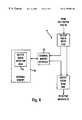
- FIG. 8is a block diagram of a linked list data structure employed in the present invention.
- FIG. 9schematically depicts a frame buffer header format in accordance with an embodiment of the present invention.
- FIG. 10is a detail of the multicopy, reclaim and free buffer pool area of the switch subsystem of FIG. 4, constructed in accordance with an embodiment of the present invention.
- FIG. 11is block diagram of a free buffer pool structure constructed in accordance with an embodiment of the present invention.
- FIG. 12is a block diagram of a multicopy queue configured in accordance with an embodiment of the present invention.
- FIG. 13is a schematic representation of the multicopy cache constructed in accordance with an embodiment of the present invention.
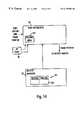
- FIG. 14is a block diagram of a queuing block of the buffer manager of the switch subsystem and a port vector FIFO, constructed in accordance with an embodiment of the present invention.
- the present inventionwill be described with the example of a switch in a packet switched network, such as an Ethernet (IEEE 802.3) network. It will become apparent, however, that the present invention is also applicable to other packet switched systems, as described in detail below, as well as to other types of systems in general.
- a packet switched networksuch as an Ethernet (IEEE 802.3) network.
- FIG. 1is a block diagram of an exemplary system in which the present invention may be advantageously employed.
- the exemplary system 10is a packet switched network, such as an Ethernet network.
- the packet switched networkincludes an integrated multiport switch (IMS) 12 that enables communication of data packets between network stations.
- the networkmay include network stations having different configurations, for example twenty-four (24) 10 megabit per second (Mbps) network stations 14 that send and receive data at a network data rate of 10 Mbps, and two 100 Mbps network stations 22 that send and receive data packets at a network speed of 100 Mbps.
- the switch 12selectively forwards data packets received from the network stations 14 or 22 to the appropriate destination based upon Ethernet protocol.
- the 10 Mbps network stations 14send and receive data packets to and from the switch 12 via a media 17 and according to half-duplex Ethernet protocol.
- the Ethernet protocol ISO/IEC 8802-3(ANSI/IEEE Std. 802.3, 1993 Ed.) defines a half-duplex media access mechanism that permits all stations 14 to access the network channel with equality. Traffic in a half-duplex environment is not distinguished or prioritized over the medium 17 . Rather, each station 14 includes an Ethernet interface card that uses carrier-sense multiple access with collision detection (CSMA/CD) to listen for traffic on the media. The absence of network traffic is detected by sensing a deassertion of a receive carrier on the media.
- CSMA/CDcarrier-sense multiple access with collision detection
- Any station 14 having data to sendwill attempt to access the channel by waiting a predetermined time after the deassertion of a receive carrier on the media, known as the interpacket gap interval (IPG). If a plurality of stations 14 have data to send on the network, each of the stations will attempt to transmit in response to the sensed deassertion of the receive carrier on the media and after the IPG interval, resulting in a collision. Hence, the transmitting station will monitor the media to determine if there has been a collision due to another station sending data at the same time. If a collision is detected, both stations stop, wait a random amount of time, and retry transmission.
- IPGinterpacket gap interval
- the 100 Mbps network stations 22preferably operate in full-duplex mode according to the proposed Ethernet standard IEEE 802.3 ⁇ Full-Duplex with Flow Control—Working Draft (0.3).
- the full-duplex environmentprovides a two-way, point-to-point communication link between each 100 Mbps network station 22 and the switch 12 , where the switch 12 and the respective stations 22 can simultaneously transmit and receive data packets without collisions.
- the 100 Mbps network stations 22each are coupled to network media 17 via 100 Mbps physical (PHY) devices 20 of type 100 Base-TX, 100 Base-T4, or 100 Base-FX.
- the switch 12includes a media independent interface (MII) 24 that provides a connection to the physical devices 20 .
- the 100 Mbps network stations 22may be implemented as servers or routers for connection to other networks.
- the network 10includes a series of switch transceivers 16 that perform time division multiplexing and time division demultiplexing for data packets transmitted between the switch 12 and the 10 Mbps stations 14 .
- a magnetic transformer module 19maintains the signal waveform shapes on the media 17 .
- the switch 12includes a transceiver interface 18 that transmits and receives data packets to and from each switch transceiver 16 using a time-division multiplexed protocol across a single serial non-return to zero (NRZ) interface 23 .
- the switch transceiver 16receives packets from the serial NRZ interface 23 , demultiplexes the received packets, and outputs the packets to the appropriate end station 14 via the network media 17 .
- each switch transceiver 16has four independent 10 Mbps twisted-pair ports and uses 4:1 multiplexing across the serial NRZ interface enabling a four-fold reduction in the number of pins required by the switch 12 .
- the switch 12contains a decision making engine, switching engine, buffer memory interface, configuration/control/status registers, management counters, and MAC (media access control) protocol interface to support the routing of data packets between the Ethernet ports serving the network stations 14 and 22 .
- the switch 12also includes enhanced functionality to make intelligent switching decisions, and to provide statistical network information in the form of management information base (MIB) objects to an external management entity, described below.
- the switch 12also includes interfaces to enable external storage of packet data and switching logic in order to minimize the chip size of the switch 12 .
- the switch 12includes a synchronous dynamic RAM (SDRAM) interface 34 that provides access to an external memory 36 for storage of received frame data, memory structures, and MIB counter information.
- SDRAMsynchronous dynamic RAM
- the memory 36may be an 80, 100 or 120 MHz synchronous DRAM having a memory size of 2 or 4 Mbytes.
- the switch 12also includes a management port 30 that enables an external management entity to control overall operations of the switch 12 by a management MAC interface 32 .
- the switch 12also includes a PCI interface 26 enabling access by the management entity via a PCI host and bridge 28 .
- the PCI host and bridge 28may serve as an expansion bus for a plurality of switch devices 12 .
- the switch 12includes an internal decision making engine (FIG. 2) that selectively transmits data packets received from one source to one, many, or no destination stations.
- the internal decision making enginemay be substituted with an external rules checker.
- the switch 12includes an external rules checker interface (ERCI) 40 that allows use of an external rules checker 42 to make frame forwarding decisions in place of the internal decision making engine. Hence, frame forwarding decisions can be made either by the internal rules checker or the external rules checker 42 .
- ERCIexternal rules checker interface
- the switch 12also includes an LED interface 44 that clocks out the status of conditions per port and drives LED external logic 46 .
- the LED external logic 46drives LED display elements 48 that are human readable.
- An oscillator 38provides a 40 MHz clock input for the system functions of the switch 12 .
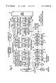
- FIG. 2is a block diagram of the integrated multiport switch (IMS) 12 of FIG. 1 .
- the switch 12includes twenty-four (24) 10 M ⁇ bps media access control (MAC) ports 50 for sending and receiving data packets in half-duplex between the respective 10 Mbps network stations 14 (ports 1-24), and two 100 Mbps MAC ports 53 for sending and receiving data packets in full-duplex between the respective 100 M ⁇ bps network stations (ports 25, 26).
- the management interface 30(port 0) also operates according to MAC layer protocol.
- Each of the MAC ports 50 , 53 and 30has a receive first in-first out (FIFO) buffer 52 and transmit FIFO 54 . Data packets from a network station are received by the corresponding MAC port and stored in the corresponding receive FIFO 52 . The received data packet is output from the corresponding receive FIFO 52 to the external memory interface 34 for storage in the external memory 36 .
- FIFOreceive first in-first out
- the header of the received packetis also forwarded to a decision making engine, either internal rules checker 58 or the external rules checker interface 40 , to determine which MAC ports will output the data packet.
- a decision making engineeither internal rules checker 58 or the external rules checker interface 40 , to determine which MAC ports will output the data packet.
- the packet headeris forwarded to the internal rules checker 58 or the external rules checker interface 40 , depending on whether the switch 12 is configured to operate using the internal rules checker 58 or the external rules checker 42 .
- the internal rules checker 58 and external rules checker 42provide the decision making logic for determining the destination MAC port for a given data packet.
- the decision making enginemay thus output a given data packet to either a single port, all ports (i.e., broadcast), or no ports (i.e., filtering).
- each data packetincludes a header having source and destination address, where the decision making engine may identify the appropriate output MAC port based upon the destination address.
- the destination addressmay correspond to a virtual address that the appropriate decision making engine identifies as corresponding to a plurality of network stations.
- the received data packetmay include a VLAN (virtual LAN) tagged frame according to IEEE 802.1d protocol that specifies another network (via a router at one of the 100 Mbps stations 22 ) or a prescribed group of stations.
- Use of the external rules checker 42provides advantages such as increased capacity, a random-based ordering in the decision queue, and enables decisions to be made in an order independent from the order in which the frames were received by the switch 12 and decision making based on a larger amount of data from the beginning of the frame (up to 64 bytes).
- the decision making enginei.e., internal rules checker 58 or the external rules checker 42 ) outputs a forwarding decision to a switch subsystem 56 in the form of a port vector identifying each MAC port that should receive the data packet.
- the port vector from the rules checkerincludes the address location storing the data packet in the external memory 36 , and the identification of the MAC ports to receive the data packet for transmission (e.g., MAC ports 0-26).
- the switch subsystem 56fetches the data packet identified in the port vector from the external memory 36 via the external memory interface 34 , and supplies the retrieved data packet to the appropriate transmit FIFO 54 of the identified ports.
- a management data interface 59enables the switch 12 to exchange control and status information with the switch transceivers 16 and the 100 Mbps physical devices 20 according to the MII management specification (IEEE 802.3u).
- the management data interface 59outputs a management data clock (MDC) providing a timing reference on the bidirectional management data IO (MDIO) signal path.
- MDCmanagement data clock
- the PCI interface 26is a 32-bit PCI revision 2.1 compliant slave interface for access by the PCI host processor 28 to internal IMS status and configuration registers 60 , and access external memory 36 .
- the PCI interface 26can also serve as an expansion bus for multiple switch devices.
- the management port 30interfaces to an external MAC engine through a standard seven-wire inverted serial GPSI interface, enabling a host controller access to the switch 12 via a standard MAC layer protocol.
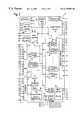
- FIG. 3depicts the switch subsystem 56 of FIG. 2 in more detail according to an exemplary embodiment of the present invention.
- Other elements of the multiport switch 12 of FIG. 2are reproduced in FIG. 3 to illustrate the connections of the switch subsystem 56 to these other elements.
- the switch subsystem 56contains the core switching engine for receiving and forwarding frames.
- the main functional blocks used to implement the switching engineinclude: a port vector FIFO 70 , a buffer manager 72 , a plurality of port output queues 74 , a management port output queue 75 , an expansion bus port output queue 77 , a free buffer pool 104 , a multicopy queue 90 , a multicopy cache 96 and a reclaim queue 98 .
- the operation and structure of these functional blockswill be described in more detail, but a brief overview of the switch subsystem 56 of FIG. 3 is first presented to provide context to the later discussion of the individual elements.
- a unicopy frameis a frame that is received at a port which is to be transmitted by the multiport switch 12 to only one other port.
- a multicopy frameis a frame that is received at one port for transmission to more than one port.
- each portis represented by a separate MAC 50 , having its own receive FIFO 52 and transmit FIFO 54 .
- Framesare received by the internal MAC engines 50 .
- the frame packetWhen the frame packet is received at the port, it is placed in the receive FIFO 52 .
- Each framehas a header, which is provided to a rules checker, either the internal rules checker 58 or the external rules checker 42 .
- the rules checker 42 or 58based on the information in the header (or in the case of 42, up to 64 bytes of data from the frame) determines from where the frame packet will be cast, i.e., through which port or ports will the frame packet be transmitted.
- the buffer manager 72obtains a free buffer pointer from the free buffer pool 104 .
- This free buffer pointeris the location in external memory 36 at which the frame will be stored by the receive FIFO 52 .
- the buffer pointed to by the free buffer pointeris no longer considered free.
- the frame datais transferred over data bus 80 from the receive FIFO 52 to the external memory 36 in a direct memory access (DMA) transaction.
- DMAdirect memory access
- the rules checker 42 or 58also receives the free buffer pointer from the buffer manager 72 .
- This free buffer pointeris now referred to as a frame pointer since it points to the memory location in the external memory 36 where the frame is stored.
- the rules checker 42 or 58uses the header information to make the forwarding decision and generate a forwarding instruction in the form of a “port vector”.
- the port vectoris a 28-bit vector with a bit set for each output port to which the frame should be forwarded. Assume for this overview example that the received frame is a unicopy frame. Accordingly, only one bit is set in the port vector generated by the rules checker 42 or 58 . The bit that is set in the port vector corresponds to a particular one of the ports.
- the rules checker 42 or 58places the port vector and the frame pointer (as well as a control opcode and a VLAN index in the case of 100 Mbps ports, management port and PCI port) into the port vector FIFO 70 .
- the port vectoris examined by the port vector FIFO 70 to determines into which particular output queue 74 (or queues) the frame pointer associated with the port vector should be input.
- the port vector FIFO 70places the frame pointer into the top of the appropriate output queue 74 . This queues the transmission of the frame.
- the frame pointerreaches the bottom of the output queue 74 after passing through the output queue 74 .
- the buffer manager 72takes the frame pointer when it arrives at the bottom of the output queue 74 and passes the frame pointer to the appropriate transmit FIFO 54 of the correct port via frame pointer read bus 86 . This schedules the transmission of the frame.
- the frame datais read in a DMA transaction from the location in external memory 36 pointed to by the frame pointer, is placed in the appropriate transmit FIFO 54 and then transmitted.
- a multicopy transmissionis similar to the unicopy transmission, except that the port vector has multiple bits set, designating the multiple ports from which the frame will be transmitted.
- the frame pointeris placed into each of the appropriate output queues 74 and transmitted from the corresponding transmit FIFOs 54 .
- the buffer manager 72uses the special control queues, i.e., the free buffer pool 104 , the multicopy queue 90 , and the reclaim queue 98 , and the multicopy cache 96 to manage the process of allocating buffers to store received frames and retrieving buffers for re-use once the frame has been transmitted to its designated output port(s).
- the buffer manager 72also maintains “overflow” regions in external memory 36 for the output queues 74 and the control queues 104 , 90 and 98 , as will be described in more detail later.
- an output queue 75is provided for the management port 30
- an output queue 77is provided for the expansion port 26 .
- These output queues 75 , 77have the same external structure as the output queues 74 , but different internal configurations, as will be described.
- FIG. 4is a block diagram of the external structure of an output queue 74 in accordance with an embodiment of the present invention.
- the output queue 74 of the present inventionhas a three-part configuration. For highest performance it is preferable to keep all of the queuing structure on the chip (referring to the multiport switch 12 ), but the real estate on a chip is very expensive. This presents a dilemma when the chip is designed to switch, and needs to queue, a large number of entries.
- the present inventionsolves this dilemma by providing a single output queue that includes a high performance, low capacity section that is on-chip, and an overflow area that is off-chip. The overflow area allows the queue to serve as a large capacity queue as needed, albeit with a relatively lower performance than the on-chip portion.
- a single logical output queue 74 of the present inventionhas three physical sections. These include an output queue write side 76 , an output queue read side 78 , and an output queue overflow area (generally designated as 110 ) located in the external memory 36 . Access to the external memory 36 for all of the output queues 74 is through the external memory interface 34 , as described earlier.
- the present inventiontakes advantage of the bursting nature of current external memories, so that the data (e.g., frame pointers) is sent on and off the chip to the overflow queue area 110 in bursts over the bus 84 connecting the chip 12 to the external memory 36 .
- the output queue write side 76 and the output queue read side 78are located on the chip 12 .
- the write side 76 and the read side 78are considered to be small, expensive resources.
- the overflow area 110forming the third part of the output queue 74 , is large and inexpensive.
- the write side 76 and the read side 78provide high performance, while the path through the overflow area provides a low-performance, large capacity path.
- the output queue write side 76receives an entry.
- the entryis a frame pointer that points to the first buffer in external memory in which the first 240 bytes of a frame are stored. It should be apparent to those of skill in the art, however, that the output queue structure 74 is not limited to frame pointers as entries, but is widely applicable to queue other types of entries, both in multiport switches and in other technologies.
- control logic associated with the output queue 74makes a decision as to what to do with the entry. If there is space in the output queue read side 78 , and the overflow area 110 for that output queue 74 is empty, then one or more entries are passed directly from the output queue write side 76 to the output queue read side. This passing of the entry or entries directly from the write side 76 to the read side 78 is performed entirely on the chip 12 , and is therefore a low-latency, fast flow-through of an entry.
- the output queue read side 78If the output queue read side 78 is full, and there is at least a burst-size amount of data (e.g., 16 bytes worth of entries) in the output queue write side 76 , then the data is written in a burst fashion into the overflow area 110 for that output queue 74 . If the output queue read side 78 is full, but there is not yet a burst-size amount of data in the output queue write side 76 , then the entry remains in the output queue write side and nothing further is done.
- a burst-size amount of datae.g. 16 bytes worth of entries
- the output queue read side 78will empty, and when the output queue read side 78 has enough space to accommodate a burst-size amount of data, and there is data in the overflow area 110 , a burst of data is provided from the overflow area 110 into the output queue read side 78 .
- the read side 78is acting most like a traditional queue, because it is from this portion that entries are taken, one by one.
- the output queue write side 76mostly serves a collection function to assemble the data into bursts for writing to the external memory 36 .
- the present inventiontransforms single events (placing an entry into the output queue 74 ) into a burst event.
- the write side 76allows an accumulation of data to then burst, if necessary, to the overflow area 110 in the external memory 36 .
- the overflow area 110provides inexpensive storage in times of congestion, rather than dedicating expensive chip resources to a function that will only be needed on relatively rare occasions.
- the accessing of this area 110is performed in a manner that is efficient, by bursting a number of bytes of information at a time. This is in contrast to conventional queuing structures in which single entries are written and read to and from the queue.
- the overflow area 110During operation, if there is a lot of entries arriving at the output queue 74 , these entries are placed into the overflow area 110 to avoid overflowing the on-chip queue 78 . Hence, the discarding of frames is largely prevented with the queue structure of the present invention. Also, the total amount of memory dedicated to the overflow areas 110 may be readily changed by changing the size of the external memory 36 . Furthermore, the sizes of the individual specific overflow areas 110 are programmable to customize the queue sizes, without impacting the performance of the output queues 74 .
- a queueis an ordered structure with a first-in, first-out arrangement.
- the order of entriesdoes not matter. If it is possible to send data directly from the write side 100 to the read side 102 , the present invention permits information to be directly sent this route, bypassing the overflow area for the queue. This is permitted even if there is information in the associated overflow area, as long as the information is not order-sensitive. For example, the reclamation of buffers is not order-sensitive, since any order in which the buffers are eventually returned to the free list in the free buffer pool 104 after the buffer is no longer needed to store the frame is acceptable.
- the informationis passed directly from the write side 100 to the read side 102 , assuming the read side 102 has room for more entries.
- the reclaim queue 98is an example of a type of queue that queues data which is not order-sensitive.
- this feature of the present inventionfinds utility in queues that queue these other types of data.
- FIGS. 1 and 2there are twenty-eight output queues (each associated with an output port): twenty-four for the 10 Mb/s user ports, two for the 100 Mb/s server ports, one for the management port and one for the expansion bus port.
- the output queues 74 , 75 and 77provide temporary storage for frame pointers when they are queued for transmission. Queuing takes the form of the port vector FIFO 70 writing frame pointers into the various output queues 74 , 75 and 77 indicated in a forwarding port vector.
- the various output queues 74 , 75 and 77contain several or all of the following fields: unicopy bit, frame pointer, control opcode or control signals, and VLAN (virtual local area network) index.
- the unicopy bitflags a frame which is to be forwarded to only one output port.
- the frame pointerpoints to the beginning of the frame in external memory 36 .
- the control opcodeidentifies special information about the address (i.e., newly learned frame, etc.).
- the control signalsuse information from the control opcode to indicate how the ports will handle frames before transmission.
- the VLAN indexprovides the reference to a VLAN tag which should be inserted (if necessary) into the outgoing frame.
- these fieldsare exemplary only, as the present invention is applicable to other output queues with different types of fields.
- the internal structure of an exemplary embodiment of a first type of output queue 74is depicted in FIG. 5 .
- the 10 Mb/s output queues 74hold entries for frames to be forwarded to the 10 Mb/s ports.
- the output queue write sides 76 for these queueshold thirty-two entries and the output queue read sides 78 hold sixteen entries in the exemplary illustrated embodiment, although other sizes are contemplated and within the scope of the invention.
- Each entry in a 10 Mb/s output queue 74comprises a unicopy bit and a frame pointer (14 bits).
- the VLAN indexis not necessary because there is no VLAN tagging on 10 Mb/s ports.
- the internal structure of an exemplary embodiment of a second type of output queue 74is depicted in FIG. 6 .
- the 100 Mb/s port output queueshold entries for frames to be forwarded to the 100 Mb/s ports.
- the output queue write side 76holds sixty-four entries in this type of output queue, and the output queue read side holds sixteen entries. Each entry comprises a VLAN index, a partial control opcode (bits 4 - 0 ), a unicopy bit and a frame pointer.
- FIG. 7An exemplary map of the external memory 36 is depicted in FIG. 7 .
- the overall capacity of the external memory 36may be, for example, 4 Mb, although other capacity memories are employed in different embodiments.
- the use of an external memory 36 for the overflow areas according to the present inventionpermits increasing or decreasing the size of the output queues by simply changing the size of the overflow area in the external memory. This is an advantage over systems in which the queue structure is entirely on the chip, as the overall queuing capacity is set at manufacture of the chip.
- an exemplary embodiment of the external memory 36allocates space for the following areas: free buffer pool overflow 120 , reclaim queue overflow 122 , multicopy queue overflow 124 , management port output queue overflow 126 , individual output queue overflows 128 for each of the 10 Mb/s and 100 Mb/s destination ports, expansion bus port output queue overflow 130 , the MIB counters 132 , and the global frame buffer pool 134 .
- the BASE Address for the entire memory regionis programmable in a memory base address register among the registers 60 on the chip.
- the BASE Address for each area in the external memory mapis programmable in the register set. No length register is required, the length for a given area being equal to the area from that area's BASE Address to the BASE Address of the next area in the mapping.
- each of the individual overflow areasSince the length (and therefore capacity) of each of the individual overflow areas is programmable, the overall capacity of each queue is programmable. This feature of the present invention permits customization of the switch to provide particular output queues with increased capacity, as needed.
- the following overflow areasstore entries that do not fit into the control queues on the chip 12 are therefore placed into the external memory 36 .
- the free buffer pool overflow area 120stores the address pointers to currently unused buffers in the global frame buffer pool 134 .
- the reclaim queue overflow area 122stores frame pointers to linked-list chains that are no longer needed.
- the following overflow areasstore entries for output queues which do not fit on-chip.
- the management port output queue overflow area 126stores frame pointers awaiting transmission to the management port.
- Output queue overflow areas 128store frame pointers awaiting transmission to the appropriate 10 Mb/s port or 100 Mb/s port.
- the expansion bus port output queue overflow area 130stores frame pointers awaiting transmission to the expansion bus port.
- the MIB counter region 132contains all the per port statistics which are updated periodically by the switch 12 .
- the switch 12maintains 8-bit and 16-bit counters on-chip for storing MIB statistics.
- the switch 12updates the 32-bit or 64-bit MIB counters in external memory 36 with the frequency required to prevent loss of MIB data.
- the global frame buffer pool 134contains buffers in linked-lists which store received frame data. At any given time, these linked lists contain valid frame data, obsolete buffers which will be returned by the buffer manager 72 to the free buffer pool 104 or are owned by the PCI host processor 28 .
- frame data received from any MAC port or the PCI busis stored in external memory 36 in a linked-list data structure format in an exemplary embodiment of the present invention.
- the buffers 140 used to create the linked-listare 256 bytes in length, although other sized buffer lengths are employed in different embodiments of the invention. Address pointers to each of these buffers 140 are stored by the free buffer pool 104 in the switch 12 .
- the buffer manager 72requests address pointers from the free buffer pool 104 for linking buffers 140 to store the frame.
- the address pointer to the first buffer in external memory 36 that stores the framebecomes the frame pointer for that frame.
- the frame pointeris used in the switch subsystem 56 for queuing frames to be transmitted.
- the buffers 140are chained together by address pointers in each buffer header 142 that indicate the location of the next buffer in memory.
- the buffer headers 142also contain other information about the frame data contained in the buffer 140 .
- the first buffer's headeris 12 bytes, as depicted in the exemplary buffer header format of FIG. 9 a .
- Each subsequent buffer's headeris 4 bytes, as depicted in FIG. 9 b .
- the first and subsequent buffer header formatscontain the following fields:
- Buffer Format Bitindicates what buffer format is in use. A one indicates the first buffer's format, which is 12 bytes in length. A zero indicates a subsequent buffer's format, which is 4 bytes. It is used for each of the remaining buffers when chaining buffers.
- E Bit(End of Frame Marker): indicates this is the last buffer for a frame. When the E bit is set, there are no more buffers in the chain.
- C BitC Bit (CRC Error Detected): indicates a CRC error was detected by the receiver.
- the transmit functionwill purposely transmit an inverted CRC.
- L Bitindicates a Frame Alignment Error was detected (along with a CRC Error) in the receive frame.
- O Bit(Receive FIFO Overflow): indicates the receive FIFO overflowed and the data in the buffer may not be valid.
- Buffer Lengththe total number of bytes which are valid in the data field of the buffer beginning with the first byte after the buffer header. This length should not include the Offset Byte value.
- Next Buffer Pointerthe pointer to the next buffer.
- the next buffer pointeris not valid when the E Bit is set.
- Offset Byte Countindicates where the first byte of the frame starts in the frame data section of the buffer. An offset of zero means the data will begin at the first byte after the buffer header 142 . An offset of zero indicates frame data will begin at the byte following the 16 th byte in the buffer. For non-zero values of offset, frame data will begin following 16B+Offset from the beginning of the buffer. The transmit function will skip over the number of bytes indicated in the offset Byte field.
- P Bitindicates the port type of the incoming receive frame. A zero indicates a 10 Mb/s port and a one indicates a 100 Mb/s port. This bit is used by the host 28 in conjunction with the time stamp field when it programs the switch 12 to forward frames to the expansion bus before the frame is completely received and buffered to external memory 36 .
- T Bitindicates the received frame type: tagged or untagged. A one indicates a tagged frame and the VLAN Identifier field contains the received VLAN ID. A zero indicates an untagged frame and the VLAN ID is not valid.
- Receive Port Numberthe number of the port from which the frame was received.
- VLAN Identifierthe VLAN ID received from a “tagged” port. If the frame was received from an untagged port, this field is invalid.
- R Bitindicates the CRC needs to be stripped and recalculated at the transmit function.
- the switch 12sets this bit when a tagged frame is received.
- the host 28modifies a frame's contents, the host 28 should set this bit.
- the switch 12transmits a frame, it will examine this bit to determine whether to transmit the existing CRC or strip and recalculate the CRC.
- a Bitindicates that there is no CRC at the end of the frame data.
- the hostcan create a frame in memory (without a CRC) then set this bit.
- the switch 12will generate and append a CRC when transmitting the frame. If the A Bit is set, the frame length should not include CRC.
- F Bitidentifies the Frame Length/Time Stamp field. A zero indicates the field is the time stamp of the incoming frame. A one indicates the field is the frame length of the received frame.
- Frame length/time stampdependent on F Bit. IF F Bit is cleared, this field represents the time stamp from the beginning of the received frame. The time stamp has a resolution of 1 ⁇ s. If the F Bit is set, indicates the total length of the received frame including CRC and any received VLAN Tag. When a frame is received, the switch 12 marks this field with the time stamp (from the timer register). If the host 28 has programmed the switch 12 to forward expansion bus frames before the frame has been completely received, it can use the time stamp (along with the speed of the receive port) to gauge how much data it can fetch from external memory 36 without over-reading the frame data. Once the entire frame has been received, the switch 12 writes the frame length into this field and sets the F Bit.
- Copy numberused to indicate the number of copies successfully queued for transmission by the port vector FIFO 70 . This field is used to store the copy number for a frame pointer if the buffer manager 72 needs to make space in the multicopy cache 96 for new entries.
- FIG. 10is a detailed depiction of some of the elements of the switch subsystem 56 of FIG. 3 . These elements are used to provide the buffers for storage of frames, and to reclaim these buffers and make them available for use again once the buffers are no longer needed for storage of the frame. As described earlier, each output queue 74 , 75 (except output queue 77 ) passes frame pointers to the buffer manager 72 , which schedules transmission of the frames pointed to by the frame pointers.
- the buffer manager 72controls the following functions: 1) managing the internal busses of the switch 12 ; 2) facilitating queuing/dequeuing frame pointers to/from the output queues 74 ; 3) managing the control queues 90 , 98 in order to locate and return buffers to the free buffer pool 104 ; 4) controlling the flow of data to and from the external memory 36 ; and 5) maintaining the memory structures, including MIBs and overflow areas.
- the buffer manager 72contains a scheduler function for allocating all accesses to external memory 36 .
- These accessesinclude 1) writing received frame data to memory buffers 140 , 2) reading frame data from memory buffers 140 for transmission and 3) maintaining (i.e., writing and reading) the frame pointers in each of the overflow areas for the output queues 74 and control queues 90 , 98 and 104 ) updating MIB counters.
- the port vector FIFO 70calculates the number of copies (the “copy number”).
- the copy numbermay be “ 0 ”, indicating that the frame should not be forwarded, a “1”, indicating a unicopy transmission, or a number “>1”, indicating a multicopy transmission.
- the port vector FIFO 70passes the frame pointer directly to the write side 100 of the reclaim queue 98 .
- the buffer manager 72breaks down the linked-list chain of buffers and returns the address pointer for each “free” buffer to the write side 106 of the free buffer pool 104 .
- the port vector FIFO 70copies the frame pointer, control signals/control opcode and the VLAN index to the output queue 74 of the appropriate port.
- the port vector FIFO 70sets the unicopy bit in the output queue 74 (see FIGS. 5 and 6) to indicate that this is a single transmission.
- the buffer manager 72reads the frame pointer and the unicopy bit from the output queue 74 of the port, it schedules the transmission as discussed previously.
- the buffer manager 72uses the frame pointer to locate the first buffer in external memory 36 in which the frame is stored.
- the buffer manager 72reads the buffer header from this first buffer, captures data from the first buffer and places this data in the appropriate MAC transmit FIFO 54 .
- the links to subsequent buffersassuming that the frame spans multiple buffers, provides the buffer manager 72 with the address to find and transmit all of the buffers in the chain for that frame.
- the port vector FIFO 70copies the frame pointer, VLAN index and control signals/control opcode to each of the appropriate output queues 74 . (When referring to queues 74 , reference is also made to queues 75 , 77 ). The port vector FIFO 70 clears the unicopy bit for the appropriate frame pointers in the output queues 74 and places the frame pointer with a copy number of “>1” into the write side 92 of the multicopy queue 90 .
- the buffer manager 72Whenever the buffer manager 72 reads a frame pointer and a cleared unicopy bit from one of the output queues 74 , the buffer manager 72 schedules the transmission of the frame, but also checks the multicopy cache 96 for an entry with a frame pointer having a copy number of “1”. If a frame pointer with a copy number of “1” is found in the multicopy cache 96 , then the buffer manager 72 schedules the frame for transmission and reclaims the buffers during transmission in the same manner as in the unicopy transmission of a frame. However, if the frame pointer is not in the multicopy cache 96 or the copy number of the frame pointer in the multicopy cache 96 is greater than 1, then the buffer manager 72 transmits the frame but does not reclaim the buffers. After successful transmission, the buffer manager 72 places a copy of the frame pointer, along with a copy number of “ ⁇ 1” into the write side 92 of the multicopy queue 90 .
- the buffer manager 72places a copy of the frame pointer into the multicopy queue 90 , provided the buffer manager 72 did not find the frame pointer in the multicopy cache 96 with a copy number of “1”.
- the multicopy queue 90may contain the frame pointer with a copy number that is >“1” and/or several copies of the same frame pointer, each with a copy number of ⁇ 1.
- the buffer manager 72constantly services the multicopy queue 90 and the multicopy cache 96 in order to reclaim obsolete buffers. When it services the multicopy queue 90 and reads a frame pointer with a copy number “>1”, the buffer manager 72 attempts to place this new entry (frame pointer and copy number) into the multicopy cache 96 . If the multicopy cache 96 is full, the buffer manager 72 makes space for the new frame pointer. The buffer manager 72 reads an “older” multicopy cache entry, updates the copy number for this entry in its buffer header in external memory 36 , then clears the entry from the multicopy cache 96 . As room becomes available in the multicopy cache 96 , the buffer manager 72 is able to place the new entry from the multicopy queue 90 into the multicopy cache 96 .
- the buffer manager 72searches the frame pointer's buffer header in external memory 36 (see FIG. 9) for the copy number. If the copy number in memory is “1”, the buffer manager 72 places the frame pointer into the reclaim queue 98 . If the copy number in memory is “>1”, the buffer manager 72 decrements the copy number, then places the frame pointer with this copy number into the multicopy cache 96 .
- the buffer manager 72constantly services the reclaim queue 98 by reading frame pointers, then “walking” the linked-list chain to return buffers to the free buffer pool 104 . This activity only returns buffers for frames that had null port vectors and were queued to the reclaim queue by the port vector FIFO 70 , or frames with a multicopy forwarding vector and have completed transmissions of all of the copies. Buffers linked for unicopy frames are returned directly to the free buffer pool 104 when the frame is transmitted, as described above.
- the port vector FIFO 70is not able to place a frame pointer for a unicopy forwarding vector into an output queue 74 , because that output queue 74 and its overflow area 110 in external memory 36 are full, the frame is discarded. The frame pointer is returned to the reclaim queue 98 and the discarding of the frame is noted by the management resources of the switch. If the port vector FIFO 70 is not able to place one or more frame pointers for a multicopy forwarding vector, because one or more of the output queues 74 and their overflow areas 110 in external memory 36 are full, the frame is only forwarded to the output queues with available space and the copy number placed into the multicopy queue 90 will only reflect the successfully placed frame pointers.
- the non-placement of the frame pointeris noted by the switch management resources for each of the ports for which the frame pointer could not be queued. If the port vector FIFO 70 is not able to place any of the frame pointers for a multicopy forwarding vector, because all of the output queues 74 and their overflow areas 110 in external memory 36 are full, the frame pointer is passed to the reclaim queue 98 , and the switch management resources are duly notified.
- the multicopy queue 90is a high priority queue used by the buffer manager 72 to keep track of how many transmissions must be completed of a particular multicopy frame before all buffers (i.e., address pointers) used to store the frame can be returned to the free buffer pool 104 .
- the write side 92 and read side 94 of this output queuehold 64 and 16 entries, respectively.
- the multicopy queue 90feeds the multicopy cache 96 , which is used by the buffer manager 72 to determine when to reclaim buffers.
- the multicopy queue internal structureis depicted in FIG. 12 .
- the port vector FIFO 70places a copy of a frame's frame pointer and copy number which is “>1”, based on the number of frame pointers it successfully placed in the output queues 74 , into the multicopy queue 90 . If a particular port's output queue 74 is full, the port vector FIFO 70 cannot place a copy of the frame pointer into the output queue 74 ; hence it cannot include this as a successful event in determining the copy number.
- the buffer manager 72Each time the buffer manager 72 reads an output queue frame pointer and finds the unicopy bit is “0”, (i.e., a multicopy), it checks the multicopy cache for the frame pointer with a copy number of “1”, which indicates that this is the last transmission. If this match is found, the buffer manager 72 transmits the frame and reclaims the buffers in the same manner as in the unicopy transmission, by providing the obsolete buffers to the free buffer pool 104 after the transmission of the contents of each buffer. If the match is not found, the buffer manager 72 transmits the multicopy frame and places a copy of the frame pointer with a copy number of “ ⁇ 1” into the multicopy queue 90 .
- This registeris one of the registers depicted in the block of registers 60 in FIG. 2 .
- the multicopy queue 90is structured with an input path and an output path.
- the input path, or write sideallows the port vector FIFO 70 and buffer manager to place frame pointers/copy numbers into the multicopy queue 90 .
- the output path, or read sideallows the multicopy queue 90 to place frame pointers/copy numbers into the multicopy cache 96 .
- Additional storage for frame pointers/copy numbers, termed the multicopy queue overflow 124is provided in external memory 36 .
- frame pointers/copy numbersWhen frame pointers/copy numbers are written into an empty multicopy queue 90 , they pass from the write side 92 to the read side 94 until the read side 94 is full. Additional frame pointers/copy numbers written to the write side 92 of the multicopy queue 90 are placed into the multicopy queue overflow area 124 in external memory 36 . Once the read side 94 of the multicopy queue 90 and its overflow area 124 are full, additional frame pointers/copy numbers placed into the multicopy queue begin to fill the write side 92 .
- the ordering of the frame pointers passing through the multicopy queue 90is maintained, such that when space clears in the multicopy queue read side 94 , frame pointers/copy numbers are moved from the multicopy queue overflow area 124 to the multicopy queue read side 94 and from the multicopy queue write side 92 to the multicopy queue overflow area 124 .
- the multicopy cache 96is similar to the multicopy queue 90 but provides a searchable region for scanning frame pointers/copy numbers.
- the multicopy cache 96holds up to 256 entries.
- the buffer manager 72reads a frame pointer from the multicopy queue 90 and either places it into the multicopy cache 96 or processes it, depending on whether the copy number is “>1” or “ ⁇ 1”.
- the buffer manager 72schedules the transmission. If the unicopy bit is “0” (meaning a multicopy frame), the buffer manager 72 scans the multicopy cache 96 for the frame pointer with a copy number of “1”, which indicates this is the last transmission of this frame. If there is a match, the buffer manager 72 removes the entry and returns buffers to the free buffer pool during frame transmission. If there is not a match, the buffer manager 72 places the frame pointer with a copy number of “ ⁇ 1” into the multicopy queue 90 upon completion of the transmission.
- the buffer manager 72services the multicopy queue 90 by reading a frame pointer/copy number and placing it into the multicopy cache 96 or processing it. This is done independently of frame transmission. Two cases follow depending on whether the buffer manager reads a frame pointer with a copy number “>1” or “ ⁇ 1”:
- the buffer manager 72reads a frame pointer with a copy number “>1” from the multicopy queue 90 . Provided there is room in the multicopy cache 96 , it writes a new entry. If the multicopy cache 96 is full, the buffer manager 72 must clear space in the cache 96 . This is done by reading one of the older frame pointer/copy numbers from the multicopy cache 96 , updating that frame pointer's buffer header in external memory 36 with the copy number in the multicopy cache 96 , then deleting this cache entry. Once there is space, the new frame pointer/copy number is written into the multicopy cache 96 .
- the buffer manager 72reads a frame pointer with a copy number “ ⁇ 1” from the multicopy queue 90 .
- the buffer manager 72finds a frame pointer match. If the multicopy cache 96 entry's copy number is “1”, the buffer manager 72 deletes the multicopy cache entry and places the frame pointer in the reclaim queue 98 . If the cache entry's copy number is “>1”, the buffer manager 72 decrements the copy number by “1”.
- the buffer manager 72does not find a frame pointer match in the multicopy cache 96 . This means that the matching frame has previously been moved to the buffer header of the frame's linked-list chain in external memory 36 .
- the buffer manager 72must go to the buffer header and read the copy number. If this value (in memory) is “1”, the frame is no longer needed and the buffer manager 72 places the frame pointer in the reclaim queue 98 . If this value (in memory) is “>1”, the buffer manager 72 decrements the copy number (that was in external memory 36 ), then places it into the multicopy cache 96 . If the multicopy cache 96 is full, the buffer manager clears space by moving one of the older frame pointer/copy numbers into external memory 36 .
- the reclaim queue 98holds the frame pointers to the linked-list chains which are no longer needed.
- the buffer manager 72writes a frame pointer to the reclaim queue when it services the multicopy cache and discovers that a frame pointer's copy number is “1” (i.e., the last transmission of the frame has completed successfully).
- the port vector FIFO 70writes frame pointers to the reclaim queue 98 under the following conditions: 1) a frame pointer's port vector is null or 2) the frame pointer could not be queued because all of the forwarding vector's output queues were full.
- the hostwrites a frame pointer to the reclaim queue 98 (using a frame pointer register) when it has finished using a unicopy frame which was queued to the expansion bus output queue 77 or the management port output queue 75 .
- the buffer manager 72When the buffer manager 72 processes reclaim queue entries, it walks a frame pointer's linked-list chain to return each buffer to the free buffer pool 104 .
- the internal structure of the reclaim queue structureis not depicted, but contains only the frame pointers (14 bits) in the exemplary embodiment of the invention.
- the reclaim queue write side 100holds 64 entries and the reclaim queue write side 102 side holds 16 entries.
- the reclaim queue 98is structured with an input path and an output path.
- the input path, or write side 100allows the buffer manager 72 to place frame pointers in the reclaim queue 98 .
- the output path, or read side 102allows the buffer manager 72 to read a frame pointer and return all associated buffers to the free buffer pool 104 . Additional storage for frame pointers is provided in the reclaim queue overflow area 122 provided in external memory 36 .
- frame pointersWhen frame pointers are written into an empty reclaim queue 98 , they pass from the write side 100 to the read side 102 until the read side 102 is full. Additional frame pointers written to the write side 100 of the reclaim queue 98 are placed into the reclaim queue overflow area 122 in external memory 36 . Once the read side 102 and overflow area 122 of the reclaim queue 98 are full, additional frame pointers placed into the reclaim queue 98 begin to fill the write side 100 .
- FIG. 11depicts an exemplary embodiment of the internal structure of the free buffer pool 104 .
- the free buffer pool 104is a FIFO that contains address pointers to all free buffers 140 in external memory 36 .
- the buffer manager 72captures available address pointers from the free buffer pool 104 to store incoming data.
- the buffer manager 72also allocates address pointers from the free buffer pool 104 to the host processor 28 (when requested).
- the hostcan request or return address pointers to the free buffer pool 104 by reading or writing a free buffer pool register among the registers 60 in direct input/output space.
- the write side 106 and the read side 108 of the free buffer pool 104each holds 64 entries in an exemplary embodiment of the invention.
- the free buffer pool 104is structured with an input path and an output path (similar to the output queues 74 ).
- the input path, or write side 106allows the buffer manager 72 or host 28 to place address pointers into the free buffer pool 104 .
- the output path, or read side 108 of the free buffer pool 104allows the buffer manager 72 to provide address pointers to the host 28 or pull address pointers from the pool 104 for storing receive frame data. Additional storage for available address pointers, the free buffer pool overflow area 120 , is provided in external memory 36 , as described earlier.
- the free buffer poolUpon start-up of the switch 12 , the free buffer pool generates address pointers from the read side 108 . As frames come in, the free list in the free buffer pool 104 is read. If there are not enough buffer pointers in the write side 106 to handle the traffic demands, the overflow area 120 is accessed to obtain more buffer pointers.
- Certain embodiments of the present inventionprovide an advantageous arrangement and method of providing the buffer pointers upon start-up of the switch 12 .
- the switch 12When the switch 12 first powers up, it is not required for the overflow area 120 in external memory 36 to contain buffer pointers. Instead, the buffer pointers are created on the fly.
- the switch 12 on power upcould generate and place into the overflow area 120 the buffer pointers, but there may be 16,000 or 32,000 such pointers, and this would slow up the powering on procedure of the switch 12 .
- the present inventiontakes advantage of the fact that on power up, all of the buffers are free, and the identities of these buffers are known. Therefore, the buffer pointers are generated as they are needed after power up, using a counter 180 , as depicted in FIG. 10 .
- the free list count generator 180is connected to the input of a multiplexer 182 . Since the free list in the free buffer pool 104 is empty on startup, the free list counter 180 generates the buffer pointers. Once the free list reaches the highest count, it will not generate any more buffer pointers.
- the frame packetWhen a frame packet is received in the switch 12 , the frame packet is broken up into fixed length buffers. Typically, frames vary in size. The buffers are 256 bytes in size and the data portion of a buffer is 240 bytes. Following transmission of the frame, the frame pointer is put into reclaim queue 98 or, in the case of an unicopy frame the individual buffer pointer in the linked list are put, directly into the free list of the free buffer pool 104 . During operation of the switch 12 , any address pointers returned to the free buffer pool 104 pass from the write side 106 to the read side 108 . If the read side 108 becomes full, additional address pointers are passed to the overflow area 120 . Once the read side 108 and the overflow area 120 are full, additional address pointers placed into the free buffer pool 104 will begin to fill the write side 106 of the pool 104 again.
- FIG. 13depicts a schematic representation of the internal arrangement of the multicopy cache 96 in accordance with an embodiment of the present invention.
- the time order of the entries to the multicopy cache 96is maintained. In the present invention, this maintaining of a time order is not done by time stamping, as in the prior art, but by physical ordering in a memory.
- the multicopy cache 96 of the present inventionalso avoids the use of validity bits, and instead encodes validity, as will be discussed.
- the multicopy cache 96is configured as a four-way set-associative memory.
- An entry into the multicopy cache 96includes a frame pointer and its copy number, as explained earlier.
- the lowest six bits of the frame pointerdetermine the row in the set-associative cache 96 in which the entry will be stored.
- there are sixty-four rows in the cache 96although other numbers of rows are not limited if the cache size is made larger.
- the set-associative cache 96is divided into four columns, each of which can be searched in parallel.
- the entryalways enters the first column, the uppermost (51:39) bits of the row indicated by the six least significant bits of the frame pointer.
- the rowis read, all of the entries are shifted to the right by 13 bits, and the row is written back.
- the entry that is actually written into the cache 96includes the upper eight bits of the frame pointer that form an address tag, and the five-bit copy number associated with the frame pointer.
- the frame pointeris re-formed with the address tag and the bits that index the row number of the cache 96 .
- the oldest entry in the cache 96is removed from the cache 96 if the row is full and a new entry to the row is written.
- the copy number associated with the frame pointer that is removedis written into the buffer header 142 of the frame in external memory pointed to by the removed frame pointer.
- the framesi.e., the buffers 140
- the frames stored in external memory 36serve as an overflow area for the multicopy cache 96 to store copy numbers.
- One of the advantageous features of the present inventionis that there is no separate valid bit in the set-associative cache 96 .
- the buffer manager 72knows that the entry is no longer valid and removes the entry from the cache 96 . This simplifies the organization of the cache.
- Another advantage of the cache 96 of the present inventionis that it allows a very fast search to be performed, since the buffer manager 72 needs only to examine a single row, already determined by the frame pointer that has exited the multicopy queue 90 . The four entries in the row are examined in parallel, further increasing the speed of the search.
- thisis exemplary only as the memory can be n-way set-associative without departing from the scope of the invention.
- the present inventionmaintains a time order (age) of the cache entries by physical positioning of the entries in the cache on a row basis.
- the physical position of the entry in the cacheis an indication of the relative age of an entry.
- the aging of an entryis performed by the physical re-ordering of the entries in the memory.
- the port vector FIFO 70examines the programmed switch mode of the receive port to determine when to place the frame pointer and associated information into the appropriate output queue 74 of the transmit port. For a first mode (low latency mode), the port vector FIFO 70 has no restrictions on when to place the frame pointer into the output queue(s) 74 . For a second mode (intermediate latency mode), the port vector FIFO 70 places the frame pointer into the output queue(s) 74 only after 64 bytes of the frame have been received. For a third mode (high latency mode), the port vector FIFO 70 places the frame pointer into the output queue(s) 70 only after the frame has been completely received.
- first modelow latency mode
- the port vector FIFO 70has no restrictions on when to place the frame pointer into the output queue(s) 74 .
- the port vector FIFO 70places the frame pointer into the output queue(s) 74 only after 64 bytes of the frame have been received.
- any frame forwarding to the expansion bus portuses the switch mode of the expansion bus port 26 .
- the queuing of the frame pointers for the entire port vectorbecomes that of the longest latency switch mode represented in the port vector. For example, if a frame is received by a first or a second mode port, but its multicopy forwarding port vector contains the management port 30 , the switch mode is the third mode. In this situation, a copy of the frame pointer is placed into all the output queues 74 only after the frame has been completely received.
- the switch mode that applies to the input (i.e., receive) portdetermines forwarding latency (how soon the switch 12 will forward a frame once it begins receiving the frame) and the ability to reduce fragment/error propagation to output ports.
- the second, intermediate latency modeis the default for each port; however, the switch mode is programmable on a per-port basis in the registers 60 .
- frame data received at the receive FIFO 52 of an internal MAC portis forwarded to a buffer 140 in the external memory 52 as soon as possible.
- the rules checker 42 or 58receives the destination address and source address, the receive port number, the frame pointer and some additional information, then performs the appropriate lookup. Once the lookup is completed, the rules checker 42 or 58 returns the frame pointer and the forwarding port vector to the port vector FIFO 70 .
- the port vector FIFO 70places the frame pointer in the write side 76 of the output queues 74 for the output port(s) identified in the port vector.
- the receive port's switch modedefines the latency between when the port vector FIFO 70 receives the port vector (and the frame pointer) and places the frame pointer into the output queue(s) 74 . This is described for the three modes below.
- the first modeis designed to provide the lowest latency. Frames are received and forwarded at line-rate speed. In this first mode, there is no network error protection because a frame is queued for transmission before it can be determined whether the frame is a fragment (i.e., ⁇ 64 bytes in length) or contains a CRC error. In the first mode, frame reception may not complete before frame transmission at the output port(s) commences. If a receive frame terminates in a runt or with an invalid CRC, the receive MAC marks the buffer header 142 in external memory 36 to indicate these conditions. The transmit MAC guarantees that if transmission commences on a frame which later terminates as a runt or with an invalid CRC, the MAC will generate a bad CRC. If the transmit MAC has not started a frame's transmission and the buffer header 142 indicates the frame terminated in a runt or an invalid CRC, the buffer manager 72 will not forward the frame to the output port.
- the second modeprovides low latency for forwarding frames and some network error protection. Frames are received and forwarded after sixty-four or more bytes have been received. This allows the switch 12 to filter (i.e., not forward) fragments of frame; however, it does not completely filter CRC error frames that are greater than sixty-four bytes.
- frame pointers for frames which achieve the sixty-four byte threshold at the receive MACare queued to the appropriate output queue(s) 74 .
- Frames which fail to achieve the minimum sixty-four byte thresholdare deleted and their frame pointers are not placed in output queue(s) 74 .
- the receive MACmarks the buffer header 142 in external memory 36 to indicate this condition. If transmission has commenced on a frame greater than or equal to sixty-four bytes which later terminates with an invalid CRC, the transmit MAC will complete the transmission with a bad CRC.
- the buffer manager 72If the transmit MAC has not started a frame transmission and the buffer header 142 indicates the frame (greater than or equal to sixty-four bytes) terminated in an invalid CRC, the buffer manager 72 returns the frame pointer to the reclaim queue 98 (for a unicopy forward) or the multicopy queue 96 (for a multicopy forward) without forwarding to the output port(s) 74 .
- the third modeis a store-and-forward mode that provides the highest level of network error protection among the three modes, but has a higher forwarding latency. Frames are completely received before the switch 12 forwarding them to output ports. In this mode, the switch 12 screens out all fragments and CRC error frames before forwarding. In the third mode, once a valid frame completes successfully at the receiver (i.e., greater than or equal to sixty-four bytes with a valid CRC), the frame pointer is queued to the appropriate output queue(s) 74 . Frames which terminate in a receive error (invalid CRC, runt (>64 bytes) etc.) are deleted and their frame pointers are not placed in output queue(s) 74 .
- the port vector FIFO 70makes the decision to put the port vector into an output queue 74 , in dependence on the selected mode of the receive port and the amount of data that has been received.
- these thresholdsare: 1) receiving n bytes (e.g. 6 bytes) where n ⁇ 64 bytes; 2) receiving 64 bytes; and 3) receiving all of the frame.
- the present inventionforwards frames to the output queues 74 based on thresholds.
- the port vector FIFO 70re-orders the sequence of transmission based on amount of type of data received and the mode in which the port is programmed.
- the exemplary embodimentmakes forwarding decisions based on the amount of received data
- other embodiments of the inventionmake forwarding decisions based on other factors, such as the types of data received.
- the buffer manager 72maintains a table 160 in a content addressable memory (CAM) 161 that associates a frame pointer with a receive port. Every time the port vector FIFO 70 receives a new port vector and frame pointer from the rules checker 42 or 58 , it makes an association to determine whether the receive port has finished receiving a frame, and if not, how much of the frame has already been received. The port vector FIFO 70 does not receive any information regarding the identity of the receive port from the rules checker 42 or 58 . The only information the port vector receives that provides any identification of the port are the frame pointers.
- CAMcontent addressable memory
- the port vector FIFO 70queries the address table 160 with the frame pointer. Either the address table returns the receive port if the frame is still being received, or the address table 160 cannot find the frame pointer which means that the frame has already been received. Once the frame is completely received, the frame pointer is moved out of the address table 160 . This means that the third threshold (the frame complete) is met. Accordingly, the frame pointer may be dropped into the output queue 74 immediately.
- the port vector FIFO 70puts the frame pointer and associated information into a holding area 162 and begins monitoring two signals from that receive port. These two signals flag one of three events. The first event is flagged when the port receives n bytes. At that point, if that port is in the first mode, the port vector FIFO 70 starts processing the frame pointer by sending it to the appropriate output queue 74 . If the receive port is not in the first mode, the port vector FIFO 70 waits until it receives the a signal indicating occurrence of the second event. If this port is in the second mode, then the port vector FIFO 70 releases the frame pointer from the holding area 162 to enter the proper output queue 74 .
- the port vector FIFO 70awaits receipt of the flag indicating that the frame is complete. Every receive port (reference numeral 164 in FIG. 14) maintains this flag, and provides this information to the port vector FIFO 70 . It is up to the port vector FIFO 70 to determine the port associated with the frame pointer. The port vector FIFO 70 maintains the information identifying the mode each port is in. In summary, upon receiving a frame pointer, the port vector FIFO 70 first queries the address table 160 of the buffer manager 72 to determine the receive port, determines the mode for that receive port, and then monitors the flags from that receive port and releases the frame pointer according to the mode and the flags.
- the buffer manager 72performs numerous functions in the switch 12 of the present invention.
- the buffer manager 72comprises control logic and/or software to implement these functions, and is readily implemented by one of ordinary skill in the art given the description of the functions of the buffer manager 72 provided above.
Landscapes
- Engineering & Computer Science (AREA)
- Computer Networks & Wireless Communication (AREA)
- Signal Processing (AREA)
- Theoretical Computer Science (AREA)
- Physics & Mathematics (AREA)
- General Engineering & Computer Science (AREA)
- General Physics & Mathematics (AREA)
- Data Exchanges In Wide-Area Networks (AREA)
Abstract
Description
Claims (13)
Priority Applications (5)
| Application Number | Priority Date | Filing Date | Title |
|---|---|---|---|
| US08/992,925US6175902B1 (en) | 1997-12-18 | 1997-12-18 | Method and apparatus for maintaining a time order by physical ordering in a memory |
| DE69807656TDE69807656T2 (en) | 1997-02-14 | 1998-01-30 | METHOD AND DEVICE FOR CONTAINING A TIMING BY PHYSICAL ORDER IN A STORAGE |
| JP53576898AJP4452781B2 (en) | 1997-02-14 | 1998-01-30 | Method and apparatus for maintaining time order by physical order in memory |
| PCT/US1998/001687WO1998036358A1 (en) | 1997-02-14 | 1998-01-30 | Method and apparatus for maintaining a time order by physical ordering in a memory |
| EP98902740AEP0960373B1 (en) | 1997-02-14 | 1998-01-30 | Method and apparatus for maintaining a time order by physical ordering in a memory |
Applications Claiming Priority (1)
| Application Number | Priority Date | Filing Date | Title |
|---|---|---|---|
| US08/992,925US6175902B1 (en) | 1997-12-18 | 1997-12-18 | Method and apparatus for maintaining a time order by physical ordering in a memory |
Publications (1)
| Publication Number | Publication Date |
|---|---|
| US6175902B1true US6175902B1 (en) | 2001-01-16 |
Family
ID=25538892
Family Applications (1)
| Application Number | Title | Priority Date | Filing Date |
|---|---|---|---|
| US08/992,925Expired - LifetimeUS6175902B1 (en) | 1997-02-14 | 1997-12-18 | Method and apparatus for maintaining a time order by physical ordering in a memory |
Country Status (1)
| Country | Link |
|---|---|
| US (1) | US6175902B1 (en) |
Cited By (81)
| Publication number | Priority date | Publication date | Assignee | Title |
|---|---|---|---|---|
| US20010033571A1 (en)* | 2000-02-28 | 2001-10-25 | Jun Cao | Switch using a segmented ring |
| US6314477B1 (en)* | 1998-10-30 | 2001-11-06 | Agilent Technologies, Inc. | Performance of fibre channel protocol sequence reassembly using expected frame information and buffer list calculations |
| US20010050912A1 (en)* | 2000-05-03 | 2001-12-13 | Govind Malalur | Gigabit switch on chip architecture |
| US6335932B2 (en)* | 1998-07-08 | 2002-01-01 | Broadcom Corporation | High performance self balancing low cost network switching architecture based on distributed hierarchical shared memory |
| US20020009084A1 (en)* | 2000-06-09 | 2002-01-24 | Broadcom Corporation | Gigabit switch supporting multiple stacking configurations |
| US20020012341A1 (en)* | 2000-06-19 | 2002-01-31 | Broadcom Corporation | Memory management unit architecture for switch fabric |
| US20020027916A1 (en)* | 2000-06-23 | 2002-03-07 | Broadcom Corporation | Switch having external address resolution interface |
| US20020034187A1 (en)* | 2000-09-20 | 2002-03-21 | Broadcom Corporation | Network switch having port blocking capability |
| US20020037006A1 (en)* | 2000-07-25 | 2002-03-28 | Broadcom Corporation | Hardware assist for address learning |
| US20020042787A1 (en)* | 2000-10-03 | 2002-04-11 | Broadcom Corporation | Switch memory management using a linked list structure |
| US20020041599A1 (en)* | 2000-10-03 | 2002-04-11 | Altima Communications Inc. | Method and apparatus for reducing clock speed and power consumption |
| US20020061030A1 (en)* | 2000-11-22 | 2002-05-23 | Ofer Iny | Method and system for switching variable sized packets |
| US20020061018A1 (en)* | 2000-10-03 | 2002-05-23 | Altima Communications, Inc. | Switch transferring data using data encapsulation and decapsulation |
| US20020069301A1 (en)* | 2000-10-03 | 2002-06-06 | Altima Communications, Inc. | Method and apparatus of inter-chip bus shared by message passing and memory access |
| US20020085586A1 (en)* | 2000-11-14 | 2002-07-04 | Altima Communications, Inc. | Linked network switch configuration |
| US20020085551A1 (en)* | 2000-11-14 | 2002-07-04 | Altima Communications, Inc. | Linked network switch configuration |
| US20020093973A1 (en)* | 2000-11-14 | 2002-07-18 | Altima Communications, Inc. | Linked network switch configuration |
| US6430188B1 (en) | 1998-07-08 | 2002-08-06 | Broadcom Corporation | Unified table for L2, L3, L4, switching and filtering |
| US20020124149A1 (en)* | 2001-03-02 | 2002-09-05 | Broadcom Corporation | Efficient optimization algorithm in memory utilization for network applications |
| US6463484B1 (en)* | 1999-07-09 | 2002-10-08 | C-Sierra, Inc. | Egress port scheduling using memory efficient request storage |
| US6487199B1 (en)* | 1999-04-07 | 2002-11-26 | Advanced Micro Devices, Inc. | Method and apparatus for maintaining randomly accessible copy number information on a network switch |
| US20020181450A1 (en)* | 2000-10-03 | 2002-12-05 | Altima Communications, Inc. | Switch having virtual shared memory |
| US6515990B1 (en)* | 1999-03-31 | 2003-02-04 | Advanced Micro Devices, Inc. | Dequeuing logic architecture and operation in a multiport communication switch |
| US20030091042A1 (en)* | 2001-10-05 | 2003-05-15 | Broadcom Corporation | Method and apparatus for enabling access on a network switch |
| US6591342B1 (en)* | 1999-12-14 | 2003-07-08 | Intel Corporation | Memory disambiguation for large instruction windows |
| US20030156586A1 (en)* | 2002-02-19 | 2003-08-21 | Broadcom Corporation | Method and apparatus for flexible frame processing and classification engine |
| US6618390B1 (en)* | 1999-05-21 | 2003-09-09 | Advanced Micro Devices, Inc. | Method and apparatus for maintaining randomly accessible free buffer information for a network switch |
| US20030196132A1 (en)* | 2002-04-15 | 2003-10-16 | Broadcom Corporation | Robust and scalable de-skew method for data path skew control |
| US20030198231A1 (en)* | 1999-06-30 | 2003-10-23 | Broadcom Corporation | Frame forwarding in a switch fabric |
| US20030212815A1 (en)* | 2002-05-09 | 2003-11-13 | Altima Communications, Inc. | Across-device communication protocol |
| US6678678B2 (en) | 2000-03-09 | 2004-01-13 | Braodcom Corporation | Method and apparatus for high speed table search |
| US20040052211A1 (en)* | 2002-09-18 | 2004-03-18 | Broadcom Corporation | Per CoS memory partitioning |
| US20040066780A1 (en)* | 2002-10-07 | 2004-04-08 | Broadcom Corporation | Fast-path implementation for transparent LAN services using double tagging |
| US20040071166A1 (en)* | 2002-10-15 | 2004-04-15 | Broadcom Corporation | Programmable inter-packet gap generator with byte granularity |
| US20040085821A1 (en)* | 2002-10-30 | 2004-05-06 | Broadcom Corporation | Self-repairing built-in self test for linked list memories |
| US20040151120A1 (en)* | 2003-02-05 | 2004-08-05 | Broadcom Corporation | Fast-path implementation for a double tagging loopback engine |
| US20040160954A1 (en)* | 2003-02-07 | 2004-08-19 | Fujitsu Limited | High speed routing table learning and lookup |
| US20040170176A1 (en)* | 1999-03-17 | 2004-09-02 | Broadcom Corporation | Method for handling IP multicast packets in network switch |
| US6826561B2 (en) | 2000-05-22 | 2004-11-30 | Broadcom Corporation | Method and apparatus for performing a binary search on an expanded tree |
| US6839349B2 (en) | 1999-12-07 | 2005-01-04 | Broadcom Corporation | Mirroring in a stacked network switch configuration |
| US20050008009A1 (en)* | 2003-06-27 | 2005-01-13 | Broadcom Corporation | Single and double tagging schemes for packet processing in a network device |
| US6850542B2 (en) | 2000-11-14 | 2005-02-01 | Broadcom Corporation | Linked network switch configuration |
| US6851000B2 (en) | 2000-10-03 | 2005-02-01 | Broadcom Corporation | Switch having flow control management |
| US20050036488A1 (en)* | 1999-05-21 | 2005-02-17 | Broadcom Corporation | Stacked network switch configuration |
| US6859454B1 (en) | 1999-06-30 | 2005-02-22 | Broadcom Corporation | Network switch with high-speed serializing/deserializing hazard-free double data rate switching |
| US20050046453A1 (en)* | 2003-09-03 | 2005-03-03 | Broadcom Corporation | Method and apparatus for glitch-free control of a delay-locked loop in a network device |
| US20050065745A1 (en)* | 2003-09-03 | 2005-03-24 | Broadcom Corporation | Method and apparatus for numeric optimization of the control of a delay-locked loop in a network device |
| US20050076238A1 (en)* | 2003-10-03 | 2005-04-07 | Ormazabal Gaston S. | Security management system for monitoring firewall operation |
| US20050122966A1 (en)* | 1999-11-16 | 2005-06-09 | Bowes Michael J. | Network switch with high-speed serializing/deserializing hazard-free double data rate switch |
| US20050141501A1 (en)* | 1999-03-17 | 2005-06-30 | Broadcom Corporation | Network switch having a programmable counter |
| US7031302B1 (en) | 1999-05-21 | 2006-04-18 | Broadcom Corporation | High-speed stats gathering in a network switch |
| US7046686B1 (en)* | 1999-08-17 | 2006-05-16 | Mindspeed Technologies, Inc. | Integrated circuit that processes communication packets with a buffer management engine having a pointer cache |
| US7082133B1 (en) | 1999-09-03 | 2006-07-25 | Broadcom Corporation | Apparatus and method for enabling voice over IP support for a network switch |
| US20060187827A1 (en)* | 2005-02-18 | 2006-08-24 | Broadcom Corporation | Programmable metering behavior based on table lookup |
| US20060187930A1 (en)* | 2005-02-18 | 2006-08-24 | Broadcom Corporation | Dynamic table sharing of memory space within a network device |
| US20060187917A1 (en)* | 2005-02-18 | 2006-08-24 | Broadcom Corporation | Pre-learning of values with later activation in a network device |
| US20060187839A1 (en)* | 2005-02-18 | 2006-08-24 | Broadcom Corporation | Timestamp metering and rollover protection in a network device |
| US20060187828A1 (en)* | 2005-02-18 | 2006-08-24 | Broadcom Corporation | Packet identifier for use in a network device |
| US20060187965A1 (en)* | 2005-02-18 | 2006-08-24 | Broadcom Corporation | Creating an IP checksum in a pipeline architecture with packet modification |
| US20060187935A1 (en)* | 2005-02-18 | 2006-08-24 | Broadcom Corporation | Bookkeeping memory use in a search engine of a network device |
| US7120117B1 (en) | 2000-08-29 | 2006-10-10 | Broadcom Corporation | Starvation free flow control in a shared memory switching device |
| US20060239264A1 (en)* | 2005-04-25 | 2006-10-26 | Samsung Electronics Co., Ltd. | Method for transmitting/receiving data in a communication system |
| US7131001B1 (en) | 1999-10-29 | 2006-10-31 | Broadcom Corporation | Apparatus and method for secure filed upgradability with hard wired public key |
| US7143294B1 (en) | 1999-10-29 | 2006-11-28 | Broadcom Corporation | Apparatus and method for secure field upgradability with unpredictable ciphertext |
| US20070140282A1 (en)* | 2005-12-21 | 2007-06-21 | Sridhar Lakshmanamurthy | Managing on-chip queues in switched fabric networks |
| US20070147380A1 (en)* | 2005-11-08 | 2007-06-28 | Ormazabal Gaston S | Systems and methods for implementing protocol-aware network firewall |
| US20070291650A1 (en)* | 2003-10-03 | 2007-12-20 | Ormazabal Gaston S | Methodology for measurements and analysis of protocol conformance, performance and scalability of stateful border gateways |
| CN100401967C (en)* | 2004-12-30 | 2008-07-16 | 天津大学 | A scrubbing device for glass windows with an angle |
| US20080222724A1 (en)* | 2006-11-08 | 2008-09-11 | Ormazabal Gaston S | PREVENTION OF DENIAL OF SERVICE (DoS) ATTACKS ON SESSION INITIATION PROTOCOL (SIP)-BASED SYSTEMS USING RETURN ROUTABILITY CHECK FILTERING |
| US20090007220A1 (en)* | 2007-06-29 | 2009-01-01 | Verizon Services Corp. | Theft of service architectural integrity validation tools for session initiation protocol (sip)-based systems |
| US20090006841A1 (en)* | 2007-06-29 | 2009-01-01 | Verizon Services Corp. | System and method for testing network firewall for denial-of-service (dos) detection and prevention in signaling channel |
| US20090083845A1 (en)* | 2003-10-03 | 2009-03-26 | Verizon Services Corp. | Network firewall test methods and apparatus |
| US7539134B1 (en) | 1999-11-16 | 2009-05-26 | Broadcom Corporation | High speed flow control methodology |
| US7593953B1 (en) | 1999-11-18 | 2009-09-22 | Broadcom Corporation | Table lookup mechanism for address resolution |
| US7606231B2 (en) | 2005-02-18 | 2009-10-20 | Broadcom Corporation | Pipeline architecture for a network device |
| US20100058457A1 (en)* | 2003-10-03 | 2010-03-04 | Verizon Services Corp. | Methodology, Measurements and Analysis of Performance and Scalability of Stateful Border Gateways |
| US20110164533A1 (en)* | 2000-07-07 | 2011-07-07 | Krumel Andrew K | Methods and systems using PLD-based network communication protocols |
| US20120278792A1 (en)* | 2011-04-29 | 2012-11-01 | International Business Machines Corporation | Automatic Verification and Synthesis for Weak Memory Models |
| US9374342B2 (en) | 2005-11-08 | 2016-06-21 | Verizon Patent And Licensing Inc. | System and method for testing network firewall using fine granularity measurements |
| US9473529B2 (en) | 2006-11-08 | 2016-10-18 | Verizon Patent And Licensing Inc. | Prevention of denial of service (DoS) attacks on session initiation protocol (SIP)-based systems using method vulnerability filtering |
| US10397670B2 (en)* | 2016-07-22 | 2019-08-27 | Intel Corporation | Techniques to process packets in a dual-mode switching environment |
Citations (11)
| Publication number | Priority date | Publication date | Assignee | Title |
|---|---|---|---|---|
| GB2107092A (en) | 1981-10-02 | 1983-04-20 | Western Electric Co | Data processing systems |
| FR2624994A1 (en) | 1987-12-18 | 1989-06-23 | Nec Corp | INTERMEDIATE TRANSLATION REGISTER CONTROL SYSTEM |
| US5155831A (en)* | 1989-04-24 | 1992-10-13 | International Business Machines Corporation | Data processing system with fast queue store interposed between store-through caches and a main memory |
| US5226125A (en)* | 1989-11-17 | 1993-07-06 | Keith Balmer | Switch matrix having integrated crosspoint logic and method of operation |
| US5256958A (en)* | 1991-11-26 | 1993-10-26 | At&T Bell Laboratories | Concentrator-based growable packet switch |
| EP0622922A1 (en) | 1993-04-29 | 1994-11-02 | International Business Machines Corporation | Method and device of multicasting data in a communications system |
| US5440546A (en)* | 1991-10-16 | 1995-08-08 | Carnegie Mellon University | Packet switch |
| US5515376A (en) | 1993-07-19 | 1996-05-07 | Alantec, Inc. | Communication apparatus and methods |
| US5590122A (en)* | 1994-12-22 | 1996-12-31 | Emc Corporation | Method and apparatus for reordering frames |
| US5842224A (en)* | 1989-06-16 | 1998-11-24 | Fenner; Peter R. | Method and apparatus for source filtering data packets between networks of differing media |
| US5953335A (en)* | 1997-02-14 | 1999-09-14 | Advanced Micro Devices, Inc. | Method and apparatus for selectively discarding packets for blocked output queues in the network switch |
- 1997
- 1997-12-18USUS08/992,925patent/US6175902B1/ennot_activeExpired - Lifetime
Patent Citations (12)
| Publication number | Priority date | Publication date | Assignee | Title |
|---|---|---|---|---|
| GB2107092A (en) | 1981-10-02 | 1983-04-20 | Western Electric Co | Data processing systems |
| FR2624994A1 (en) | 1987-12-18 | 1989-06-23 | Nec Corp | INTERMEDIATE TRANSLATION REGISTER CONTROL SYSTEM |
| US4980816A (en)* | 1987-12-18 | 1990-12-25 | Nec Corporation | Translation look-aside buffer control system with multiple prioritized buffers |
| US5155831A (en)* | 1989-04-24 | 1992-10-13 | International Business Machines Corporation | Data processing system with fast queue store interposed between store-through caches and a main memory |
| US5842224A (en)* | 1989-06-16 | 1998-11-24 | Fenner; Peter R. | Method and apparatus for source filtering data packets between networks of differing media |
| US5226125A (en)* | 1989-11-17 | 1993-07-06 | Keith Balmer | Switch matrix having integrated crosspoint logic and method of operation |
| US5440546A (en)* | 1991-10-16 | 1995-08-08 | Carnegie Mellon University | Packet switch |
| US5256958A (en)* | 1991-11-26 | 1993-10-26 | At&T Bell Laboratories | Concentrator-based growable packet switch |
| EP0622922A1 (en) | 1993-04-29 | 1994-11-02 | International Business Machines Corporation | Method and device of multicasting data in a communications system |
| US5515376A (en) | 1993-07-19 | 1996-05-07 | Alantec, Inc. | Communication apparatus and methods |
| US5590122A (en)* | 1994-12-22 | 1996-12-31 | Emc Corporation | Method and apparatus for reordering frames |
| US5953335A (en)* | 1997-02-14 | 1999-09-14 | Advanced Micro Devices, Inc. | Method and apparatus for selectively discarding packets for blocked output queues in the network switch |
Non-Patent Citations (1)
| Title |
|---|
| Kenneth J. Schultz et al., "Cam-Based Single-Chip Shared Buffer ATM Switch", Supercomm/ICC, New Orleans, May 1-5, vol. 2, Institute of Electrical and Electronics Engineers, 1994, pp. 1190-1195. |
Cited By (226)
| Publication number | Priority date | Publication date | Assignee | Title |
|---|---|---|---|---|
| US6430188B1 (en) | 1998-07-08 | 2002-08-06 | Broadcom Corporation | Unified table for L2, L3, L4, switching and filtering |
| US7103055B2 (en) | 1998-07-08 | 2006-09-05 | Broadcom Corporation | Unified table for L2, L3, L4, switching and filtering |
| US6335932B2 (en)* | 1998-07-08 | 2002-01-01 | Broadcom Corporation | High performance self balancing low cost network switching architecture based on distributed hierarchical shared memory |
| US20020186705A1 (en)* | 1998-07-08 | 2002-12-12 | Shiri Kadambi | Unified table for L2, L3, L4, switching and filtering |
| US6643261B2 (en) | 1998-07-08 | 2003-11-04 | Broadcom Corporation | High performance self balancing low cost network switching architecture based on distributed hierarchical shared memory |
| US6795447B2 (en) | 1998-07-08 | 2004-09-21 | Broadcom Corporation | High performance self balancing low cost network switching architecture based on distributed hierarchical shared |
| US6314477B1 (en)* | 1998-10-30 | 2001-11-06 | Agilent Technologies, Inc. | Performance of fibre channel protocol sequence reassembly using expected frame information and buffer list calculations |
| US8411574B2 (en) | 1999-03-05 | 2013-04-02 | Broadcom Corporation | Starvation free flow control in a shared memory switching device |
| US20060291458A1 (en)* | 1999-03-05 | 2006-12-28 | Broadcom Corporation | Starvation free flow control in a shared memory switching device |
| US7782891B2 (en) | 1999-03-17 | 2010-08-24 | Broadcom Corporation | Network switch memory interface configuration |
| US20080056278A1 (en)* | 1999-03-17 | 2008-03-06 | Broadcom Corporation | Network switch memory interface configuration |
| US20050141501A1 (en)* | 1999-03-17 | 2005-06-30 | Broadcom Corporation | Network switch having a programmable counter |
| US7720055B2 (en) | 1999-03-17 | 2010-05-18 | Broadcom Corporation | Method for handling IP multicast packets in network switch |
| US20040170176A1 (en)* | 1999-03-17 | 2004-09-02 | Broadcom Corporation | Method for handling IP multicast packets in network switch |
| US7643481B2 (en) | 1999-03-17 | 2010-01-05 | Broadcom Corporation | Network switch having a programmable counter |
| US6515990B1 (en)* | 1999-03-31 | 2003-02-04 | Advanced Micro Devices, Inc. | Dequeuing logic architecture and operation in a multiport communication switch |
| US6487199B1 (en)* | 1999-04-07 | 2002-11-26 | Advanced Micro Devices, Inc. | Method and apparatus for maintaining randomly accessible copy number information on a network switch |
| US6618390B1 (en)* | 1999-05-21 | 2003-09-09 | Advanced Micro Devices, Inc. | Method and apparatus for maintaining randomly accessible free buffer information for a network switch |
| US20050036488A1 (en)* | 1999-05-21 | 2005-02-17 | Broadcom Corporation | Stacked network switch configuration |
| US7031302B1 (en) | 1999-05-21 | 2006-04-18 | Broadcom Corporation | High-speed stats gathering in a network switch |
| US7593403B2 (en) | 1999-05-21 | 2009-09-22 | Broadcom Corporation | Stacked network switch configuration |
| US20030198231A1 (en)* | 1999-06-30 | 2003-10-23 | Broadcom Corporation | Frame forwarding in a switch fabric |
| US6859454B1 (en) | 1999-06-30 | 2005-02-22 | Broadcom Corporation | Network switch with high-speed serializing/deserializing hazard-free double data rate switching |
| US7315552B2 (en) | 1999-06-30 | 2008-01-01 | Broadcom Corporation | Frame forwarding in a switch fabric |
| US6463484B1 (en)* | 1999-07-09 | 2002-10-08 | C-Sierra, Inc. | Egress port scheduling using memory efficient request storage |
| USRE42092E1 (en) | 1999-08-17 | 2011-02-01 | Tompkins Joseph B | Integrated circuit that processes communication packets with a buffer management engine having a pointer cache |
| US7046686B1 (en)* | 1999-08-17 | 2006-05-16 | Mindspeed Technologies, Inc. | Integrated circuit that processes communication packets with a buffer management engine having a pointer cache |
| US7577148B2 (en) | 1999-09-03 | 2009-08-18 | Broadcom Corporation | Apparatus and method for enabling Voice Over IP support for a network switch |
| US7082133B1 (en) | 1999-09-03 | 2006-07-25 | Broadcom Corporation | Apparatus and method for enabling voice over IP support for a network switch |
| US20060209807A1 (en)* | 1999-09-03 | 2006-09-21 | Broadcom Corporation | Apparatus and method for enabling voice over IP support for a network switch |
| US7634665B2 (en) | 1999-10-29 | 2009-12-15 | Broadcom Corporation | Apparatus and method for secure field upgradability with unpredictable ciphertext |
| US7131001B1 (en) | 1999-10-29 | 2006-10-31 | Broadcom Corporation | Apparatus and method for secure filed upgradability with hard wired public key |
| US7143294B1 (en) | 1999-10-29 | 2006-11-28 | Broadcom Corporation | Apparatus and method for secure field upgradability with unpredictable ciphertext |
| US20080040617A1 (en)* | 1999-10-29 | 2008-02-14 | Broadcom Corporation | Apparatus and method for secure field upgradability with unpredictable ciphertext |
| US20050122966A1 (en)* | 1999-11-16 | 2005-06-09 | Bowes Michael J. | Network switch with high-speed serializing/deserializing hazard-free double data rate switch |
| US20100135289A1 (en)* | 1999-11-16 | 2010-06-03 | Broadcom Corporation | High speed flow control methodology |
| US7366208B2 (en) | 1999-11-16 | 2008-04-29 | Broadcom | Network switch with high-speed serializing/deserializing hazard-free double data rate switch |
| US8081570B2 (en) | 1999-11-16 | 2011-12-20 | Broadcom Corporation | High speed flow control methodology |
| US7539134B1 (en) | 1999-11-16 | 2009-05-26 | Broadcom Corporation | High speed flow control methodology |
| US7593953B1 (en) | 1999-11-18 | 2009-09-22 | Broadcom Corporation | Table lookup mechanism for address resolution |
| US8086571B2 (en) | 1999-11-18 | 2011-12-27 | Broadcom Corporation | Table lookup mechanism for address resolution |
| US20100014516A1 (en)* | 1999-11-18 | 2010-01-21 | Broadcom Corporation | Table lookup mechanism for address resolution |
| US20050074006A1 (en)* | 1999-12-07 | 2005-04-07 | Broadcom Corporation | Mirroring in a stacked network switch configuration |
| US6839349B2 (en) | 1999-12-07 | 2005-01-04 | Broadcom Corporation | Mirroring in a stacked network switch configuration |
| US7715328B2 (en) | 1999-12-07 | 2010-05-11 | Broadcom Corporation | Mirroring in a stacked network switch configuration |
| US6591342B1 (en)* | 1999-12-14 | 2003-07-08 | Intel Corporation | Memory disambiguation for large instruction windows |
| US7418552B2 (en) | 1999-12-14 | 2008-08-26 | Intel Corporation | Memory disambiguation for large instruction windows |
| US20030196075A1 (en)* | 1999-12-14 | 2003-10-16 | Intel Corporation | Memory disambiguation for large instruction windows |
| US7009973B2 (en) | 2000-02-28 | 2006-03-07 | Broadcom Corporation | Switch using a segmented ring |
| US20010033571A1 (en)* | 2000-02-28 | 2001-10-25 | Jun Cao | Switch using a segmented ring |
| US6678678B2 (en) | 2000-03-09 | 2004-01-13 | Braodcom Corporation | Method and apparatus for high speed table search |
| US7260565B2 (en) | 2000-03-09 | 2007-08-21 | Broadcom Corporation | Method and apparatus for high speed table search |
| US20040139071A1 (en)* | 2000-03-09 | 2004-07-15 | Broadcom Corporation | Method and apparatus for high speed table search |
| US7675924B2 (en) | 2000-05-03 | 2010-03-09 | Broadcom Corporation | Gigabit switch on chip architecture |
| US20060274786A1 (en)* | 2000-05-03 | 2006-12-07 | Broadcom Corporation | Gigabit switch on chip architecture |
| US7103053B2 (en) | 2000-05-03 | 2006-09-05 | Broadcom Corporation | Gigabit switch on chip architecture |
| US20010050912A1 (en)* | 2000-05-03 | 2001-12-13 | Govind Malalur | Gigabit switch on chip architecture |
| US7610271B2 (en) | 2000-05-22 | 2009-10-27 | Broadcom Corporation | Method and apparatus for performing a binary search on an expanded tree |
| US6826561B2 (en) | 2000-05-22 | 2004-11-30 | Broadcom Corporation | Method and apparatus for performing a binary search on an expanded tree |
| US7072885B2 (en) | 2000-05-22 | 2006-07-04 | Broadcom Corporation | Method and apparatus for performing a binary search on an expanded tree |
| US20050071501A1 (en)* | 2000-05-22 | 2005-03-31 | Broadcom Corporation | Method and apparatus for performing a binary search on an expanded tree |
| US7075939B2 (en) | 2000-06-09 | 2006-07-11 | Broadcom Corporation | Flexible header protocol for network switch |
| US20060251085A1 (en)* | 2000-06-09 | 2006-11-09 | Broadcom Corporation | Cascading of gigabit switches |
| US20020018489A1 (en)* | 2000-06-09 | 2002-02-14 | Broadcom Corporation | Gigabit switch supporting improved layer 3 switching |
| US7046679B2 (en)* | 2000-06-09 | 2006-05-16 | Broadcom Corporation | Gigabit switch with frame forwarding and address learning |
| US7106736B2 (en) | 2000-06-09 | 2006-09-12 | Broadcom Corporation | Gigabit switch supporting multiple stacking configurations |
| US20020009084A1 (en)* | 2000-06-09 | 2002-01-24 | Broadcom Corporation | Gigabit switch supporting multiple stacking configurations |
| US20020012585A1 (en)* | 2000-06-09 | 2002-01-31 | Broadcom Corporation | Gigabit switch with fast filtering processor |
| US7050430B2 (en) | 2000-06-09 | 2006-05-23 | Broadcom Corporation | Gigabit switch with fast filtering processor |
| US7710954B2 (en) | 2000-06-09 | 2010-05-04 | Broadcom Corporation | Cascading of gigabit switches |
| US7009968B2 (en) | 2000-06-09 | 2006-03-07 | Broadcom Corporation | Gigabit switch supporting improved layer 3 switching |
| US20020009081A1 (en)* | 2000-06-09 | 2002-01-24 | Broadcom Corporation | Gigabit switch with frame forwarding and address learning |
| US20020012345A1 (en)* | 2000-06-09 | 2002-01-31 | Broadcom Corporation | Cascading of gigabit switches |
| US7099317B2 (en) | 2000-06-09 | 2006-08-29 | Broadcom Corporation | Gigabit switch with multicast handling |
| US20020010791A1 (en)* | 2000-06-09 | 2002-01-24 | Broadcom Corporation | Trunking and mirroring across stacked gigabit switches |
| US20020009083A1 (en)* | 2000-06-09 | 2002-01-24 | Broadcom Corporation | Gigabit switch with multicast handling |
| US7020139B2 (en) | 2000-06-09 | 2006-03-28 | Broadcom Corporation | Trunking and mirroring across stacked gigabit switches |
| US20020009090A1 (en)* | 2000-06-09 | 2002-01-24 | Broadcom Corporation | Flexible header protocol for network switch |
| US7796612B2 (en) | 2000-06-09 | 2010-09-14 | Broadcom Corporation | Gigabit switch with frame forwarding and address learning |
| US7139269B2 (en) | 2000-06-09 | 2006-11-21 | Broadcom Corporation | Cascading of gigabit switches |
| US20060120389A1 (en)* | 2000-06-09 | 2006-06-08 | Broadcom Corporation | Gigabit switch with frame forwarding and address learning |
| US20020012341A1 (en)* | 2000-06-19 | 2002-01-31 | Broadcom Corporation | Memory management unit architecture for switch fabric |
| US20030118016A1 (en)* | 2000-06-19 | 2003-06-26 | Broadcom Corporation | Switch fabric with path redundancy |
| US6950430B2 (en) | 2000-06-19 | 2005-09-27 | Broadcom Corporation | Switch fabric with path redundancy |
| US7136381B2 (en) | 2000-06-19 | 2006-11-14 | Broadcom Corporation | Memory management unit architecture for switch fabric |
| US20090196303A1 (en)* | 2000-06-19 | 2009-08-06 | Broadcom Corporation | Switch fabric with memory management unit for improved flow control |
| US7519059B2 (en) | 2000-06-19 | 2009-04-14 | Broadcom Corporation | Switch fabric with memory management unit for improved flow control |
| US6535510B2 (en) | 2000-06-19 | 2003-03-18 | Broadcom Corporation | Switch fabric with path redundancy |
| US8274971B2 (en) | 2000-06-19 | 2012-09-25 | Broadcom Corporation | Switch fabric with memory management unit for improved flow control |
| US6567417B2 (en) | 2000-06-19 | 2003-05-20 | Broadcom Corporation | Frame forwarding in a switch fabric |
| US20060256787A1 (en)* | 2000-06-23 | 2006-11-16 | Broadcom Corporation | Switch having external address resolution interface |
| US7126947B2 (en) | 2000-06-23 | 2006-10-24 | Broadcom Corporation | Switch having external address resolution interface |
| US8027341B2 (en) | 2000-06-23 | 2011-09-27 | Broadcom Corporation | Switch having external address resolution interface |
| US20020027916A1 (en)* | 2000-06-23 | 2002-03-07 | Broadcom Corporation | Switch having external address resolution interface |
| US20110164533A1 (en)* | 2000-07-07 | 2011-07-07 | Krumel Andrew K | Methods and systems using PLD-based network communication protocols |
| US8879427B2 (en)* | 2000-07-07 | 2014-11-04 | 802 Systems Inc. | Methods for updating the configuration of a programmable packet filtering device including a determination as to whether a packet is to be junked |
| US6999455B2 (en) | 2000-07-25 | 2006-02-14 | Broadcom Corporation | Hardware assist for address learning |
| US20020037006A1 (en)* | 2000-07-25 | 2002-03-28 | Broadcom Corporation | Hardware assist for address learning |
| US7120117B1 (en) | 2000-08-29 | 2006-10-10 | Broadcom Corporation | Starvation free flow control in a shared memory switching device |
| US7856015B2 (en) | 2000-09-20 | 2010-12-21 | Broadcom Corporation | Network switch having port blocking capability |
| US7227862B2 (en) | 2000-09-20 | 2007-06-05 | Broadcom Corporation | Network switch having port blocking capability |
| US20070201466A1 (en)* | 2000-09-20 | 2007-08-30 | Broadcom Corporation | Network switch having port blocking capability |
| US20020034187A1 (en)* | 2000-09-20 | 2002-03-21 | Broadcom Corporation | Network switch having port blocking capability |
| US7120155B2 (en) | 2000-10-03 | 2006-10-10 | Broadcom Corporation | Switch having virtual shared memory |
| US6988177B2 (en) | 2000-10-03 | 2006-01-17 | Broadcom Corporation | Switch memory management using a linked list structure |
| US20020042787A1 (en)* | 2000-10-03 | 2002-04-11 | Broadcom Corporation | Switch memory management using a linked list structure |
| US20020041599A1 (en)* | 2000-10-03 | 2002-04-11 | Altima Communications Inc. | Method and apparatus for reducing clock speed and power consumption |
| US7274705B2 (en) | 2000-10-03 | 2007-09-25 | Broadcom Corporation | Method and apparatus for reducing clock speed and power consumption |
| US20050073957A1 (en)* | 2000-10-03 | 2005-04-07 | Broadcom Corporation | Switch having flow control management |
| US20020061018A1 (en)* | 2000-10-03 | 2002-05-23 | Altima Communications, Inc. | Switch transferring data using data encapsulation and decapsulation |
| US20020069301A1 (en)* | 2000-10-03 | 2002-06-06 | Altima Communications, Inc. | Method and apparatus of inter-chip bus shared by message passing and memory access |
| US20020181450A1 (en)* | 2000-10-03 | 2002-12-05 | Altima Communications, Inc. | Switch having virtual shared memory |
| US7420977B2 (en) | 2000-10-03 | 2008-09-02 | Broadcom Corporation | Method and apparatus of inter-chip bus shared by message passing and memory access |
| US6851000B2 (en) | 2000-10-03 | 2005-02-01 | Broadcom Corporation | Switch having flow control management |
| US20050235129A1 (en)* | 2000-10-03 | 2005-10-20 | Broadcom Corporation | Switch memory management using a linked list structure |
| US7656907B2 (en) | 2000-10-03 | 2010-02-02 | Broadcom Corporation | Method and apparatus for reducing clock speed and power consumption |
| US7020166B2 (en) | 2000-10-03 | 2006-03-28 | Broadcom Corporation | Switch transferring data using data encapsulation and decapsulation |
| US7050431B2 (en) | 2000-11-14 | 2006-05-23 | Broadcom Corporation | Linked network switch configuration |
| US7035255B2 (en) | 2000-11-14 | 2006-04-25 | Broadcom Corporation | Linked network switch configuration |
| US7035286B2 (en) | 2000-11-14 | 2006-04-25 | Broadcom Corporation | Linked network switch configuration |
| US20020085551A1 (en)* | 2000-11-14 | 2002-07-04 | Altima Communications, Inc. | Linked network switch configuration |
| US20090003213A1 (en)* | 2000-11-14 | 2009-01-01 | Broadcom Corporation | Linked network switch configuration |
| US20050105539A1 (en)* | 2000-11-14 | 2005-05-19 | Broadcom Corporation | Linked network switch configuration |
| US20020093973A1 (en)* | 2000-11-14 | 2002-07-18 | Altima Communications, Inc. | Linked network switch configuration |
| US7424012B2 (en) | 2000-11-14 | 2008-09-09 | Broadcom Corporation | Linked network switch configuration |
| US20020085586A1 (en)* | 2000-11-14 | 2002-07-04 | Altima Communications, Inc. | Linked network switch configuration |
| US20050122825A1 (en)* | 2000-11-14 | 2005-06-09 | Broadcom Corporation | Linked network switch configuration |
| US7792104B2 (en) | 2000-11-14 | 2010-09-07 | Broadcom Corporation | Linked network switch configuration |
| US7339938B2 (en) | 2000-11-14 | 2008-03-04 | Broadcom Corporation | Linked network switch configuration |
| US6850542B2 (en) | 2000-11-14 | 2005-02-01 | Broadcom Corporation | Linked network switch configuration |
| US7095744B2 (en) | 2000-11-22 | 2006-08-22 | Dune Networks | Method and system for switching variable sized packets |
| US7525995B2 (en) | 2000-11-22 | 2009-04-28 | Dune Networks Inc. | Method and system for switching packets |
| US20050174940A1 (en)* | 2000-11-22 | 2005-08-11 | Ofer Iny | Method and system for switching packets |
| US20020061030A1 (en)* | 2000-11-22 | 2002-05-23 | Ofer Iny | Method and system for switching variable sized packets |
| US20020124149A1 (en)* | 2001-03-02 | 2002-09-05 | Broadcom Corporation | Efficient optimization algorithm in memory utilization for network applications |
| US7324509B2 (en) | 2001-03-02 | 2008-01-29 | Broadcom Corporation | Efficient optimization algorithm in memory utilization for network applications |
| US20030091042A1 (en)* | 2001-10-05 | 2003-05-15 | Broadcom Corporation | Method and apparatus for enabling access on a network switch |
| US7355970B2 (en) | 2001-10-05 | 2008-04-08 | Broadcom Corporation | Method and apparatus for enabling access on a network switch |
| US20030156586A1 (en)* | 2002-02-19 | 2003-08-21 | Broadcom Corporation | Method and apparatus for flexible frame processing and classification engine |
| US7719980B2 (en) | 2002-02-19 | 2010-05-18 | Broadcom Corporation | Method and apparatus for flexible frame processing and classification engine |
| US6996738B2 (en) | 2002-04-15 | 2006-02-07 | Broadcom Corporation | Robust and scalable de-skew method for data path skew control |
| US20030196132A1 (en)* | 2002-04-15 | 2003-10-16 | Broadcom Corporation | Robust and scalable de-skew method for data path skew control |
| US20060026449A1 (en)* | 2002-04-15 | 2006-02-02 | Broadcom Corporation | Robust and scalable de-skew method |
| US20070083786A1 (en)* | 2002-04-15 | 2007-04-12 | Broadcom Corporation | Robust and scalable de-skew method for data path skew control |
| US7167995B2 (en) | 2002-04-15 | 2007-01-23 | Broadcom Corporation | Robust and scalable de-skew method |
| US7328362B2 (en) | 2002-04-15 | 2008-02-05 | Broadcom Corporation | Method and apparatus for selectively deskewing data traveling through a bus |
| US8190766B2 (en) | 2002-05-09 | 2012-05-29 | Broadcom Corporation | Across-device communication protocol |
| US20030212815A1 (en)* | 2002-05-09 | 2003-11-13 | Altima Communications, Inc. | Across-device communication protocol |
| US7124168B2 (en) | 2002-09-18 | 2006-10-17 | Broadcom Corporation | Per CoS memory partitioning |
| US7953001B2 (en) | 2002-09-18 | 2011-05-31 | Broadcom Corporation | Per CoS memory partitioning |
| US20070002746A1 (en)* | 2002-09-18 | 2007-01-04 | Broadcom Corporation | Per CoS memory partitioning |
| US20050207426A1 (en)* | 2002-09-18 | 2005-09-22 | Broadcom Corporation | Per CoS memory partitioning |
| US20040052211A1 (en)* | 2002-09-18 | 2004-03-18 | Broadcom Corporation | Per CoS memory partitioning |
| US6907453B2 (en) | 2002-09-18 | 2005-06-14 | Broadcom Corporation | Per CoS memory partitioning |
| US7515592B2 (en) | 2002-10-07 | 2009-04-07 | Broadcom Corporation | Fast-path implementation for transparent LAN services using double tagging |
| US20040066780A1 (en)* | 2002-10-07 | 2004-04-08 | Broadcom Corporation | Fast-path implementation for transparent LAN services using double tagging |
| US7184404B2 (en) | 2002-10-15 | 2007-02-27 | Broadcom Corporation | Programmable inter-packet gap generator with byte granularity |
| US20040071166A1 (en)* | 2002-10-15 | 2004-04-15 | Broadcom Corporation | Programmable inter-packet gap generator with byte granularity |
| US6781898B2 (en) | 2002-10-30 | 2004-08-24 | Broadcom Corporation | Self-repairing built-in self test for linked list memories |
| US20040085821A1 (en)* | 2002-10-30 | 2004-05-06 | Broadcom Corporation | Self-repairing built-in self test for linked list memories |
| US6917548B2 (en) | 2002-10-30 | 2005-07-12 | Broadcom Corporation | Self-repairing built-in self test for linked list memories |
| US20040257891A1 (en)* | 2002-10-30 | 2004-12-23 | Broadcom Corporation | Self-repairing built-in self test for linked list memories |
| US20080095062A1 (en)* | 2003-02-05 | 2008-04-24 | Broadcom Corporation | Fastpath implementation for a double tagging loopback engine |
| US7298705B2 (en) | 2003-02-05 | 2007-11-20 | Broadcom Corporation | Fast-path implementation for a double tagging loopback engine |
| US7636319B2 (en) | 2003-02-05 | 2009-12-22 | Broadcom Corporation | Fastpath implementation for a double tagging loopback engine |
| US20040151120A1 (en)* | 2003-02-05 | 2004-08-05 | Broadcom Corporation | Fast-path implementation for a double tagging loopback engine |
| US7477639B2 (en)* | 2003-02-07 | 2009-01-13 | Fujitsu Limited | High speed routing table learning and lookup |
| US20040160954A1 (en)* | 2003-02-07 | 2004-08-19 | Fujitsu Limited | High speed routing table learning and lookup |
| US20050008009A1 (en)* | 2003-06-27 | 2005-01-13 | Broadcom Corporation | Single and double tagging schemes for packet processing in a network device |
| US7974284B2 (en) | 2003-06-27 | 2011-07-05 | Broadcom Corporation | Single and double tagging schemes for packet processing in a network device |
| US7132866B2 (en) | 2003-09-03 | 2006-11-07 | Broadcom Corporation | Method and apparatus for glitch-free control of a delay-locked loop in a network device |
| US7064592B2 (en) | 2003-09-03 | 2006-06-20 | Broadcom Corporation | Method and apparatus for numeric optimization of the control of a delay-locked loop in a network device |
| US7348820B2 (en) | 2003-09-03 | 2008-03-25 | Broadcom Corporation | Method and apparatus for glitch-free control of a delay-locked loop in a network device |
| US20050065745A1 (en)* | 2003-09-03 | 2005-03-24 | Broadcom Corporation | Method and apparatus for numeric optimization of the control of a delay-locked loop in a network device |
| US20050046453A1 (en)* | 2003-09-03 | 2005-03-03 | Broadcom Corporation | Method and apparatus for glitch-free control of a delay-locked loop in a network device |
| US8925063B2 (en) | 2003-10-03 | 2014-12-30 | Verizon Patent And Licensing Inc. | Security management system for monitoring firewall operation |
| US20090205039A1 (en)* | 2003-10-03 | 2009-08-13 | Verizon Services Corp. | Security management system for monitoring firewall operation |
| US20100058457A1 (en)* | 2003-10-03 | 2010-03-04 | Verizon Services Corp. | Methodology, Measurements and Analysis of Performance and Scalability of Stateful Border Gateways |
| US8509095B2 (en) | 2003-10-03 | 2013-08-13 | Verizon Services Corp. | Methodology for measurements and analysis of protocol conformance, performance and scalability of stateful border gateways |
| US8015602B2 (en) | 2003-10-03 | 2011-09-06 | Verizon Services Corp. | Methodology, measurements and analysis of performance and scalability of stateful border gateways |
| US8046828B2 (en) | 2003-10-03 | 2011-10-25 | Verizon Services Corp. | Security management system for monitoring firewall operation |
| US8001589B2 (en) | 2003-10-03 | 2011-08-16 | Verizon Services Corp. | Network firewall test methods and apparatus |
| US7853996B1 (en) | 2003-10-03 | 2010-12-14 | Verizon Services Corp. | Methodology, measurements and analysis of performance and scalability of stateful border gateways |
| US20050076238A1 (en)* | 2003-10-03 | 2005-04-07 | Ormazabal Gaston S. | Security management system for monitoring firewall operation |
| US7886348B2 (en) | 2003-10-03 | 2011-02-08 | Verizon Services Corp. | Security management system for monitoring firewall operation |
| US20090083845A1 (en)* | 2003-10-03 | 2009-03-26 | Verizon Services Corp. | Network firewall test methods and apparatus |
| US20070291650A1 (en)* | 2003-10-03 | 2007-12-20 | Ormazabal Gaston S | Methodology for measurements and analysis of protocol conformance, performance and scalability of stateful border gateways |
| US7886350B2 (en) | 2003-10-03 | 2011-02-08 | Verizon Services Corp. | Methodology for measurements and analysis of protocol conformance, performance and scalability of stateful border gateways |
| CN100401967C (en)* | 2004-12-30 | 2008-07-16 | 天津大学 | A scrubbing device for glass windows with an angle |
| US7983169B2 (en) | 2005-02-18 | 2011-07-19 | Broadcom Corporation | Programmable metering behavior based on a table lookup |
| US20060187930A1 (en)* | 2005-02-18 | 2006-08-24 | Broadcom Corporation | Dynamic table sharing of memory space within a network device |
| US20060187935A1 (en)* | 2005-02-18 | 2006-08-24 | Broadcom Corporation | Bookkeeping memory use in a search engine of a network device |
| US7577096B2 (en) | 2005-02-18 | 2009-08-18 | Broadcom Corporation | Timestamp metering and rollover protection in a network device |
| US8566337B2 (en) | 2005-02-18 | 2013-10-22 | Broadcom Corporation | Pipeline architecture for a network device |
| US20100202295A1 (en)* | 2005-02-18 | 2010-08-12 | Broadcom Corporation | Programmable metering behavior based on a table lookup |
| US20060187965A1 (en)* | 2005-02-18 | 2006-08-24 | Broadcom Corporation | Creating an IP checksum in a pipeline architecture with packet modification |
| US8457131B2 (en) | 2005-02-18 | 2013-06-04 | Broadcom Corporation | Dynamic table sharing of memory space within a network device |
| US7606231B2 (en) | 2005-02-18 | 2009-10-20 | Broadcom Corporation | Pipeline architecture for a network device |
| US20060187828A1 (en)* | 2005-02-18 | 2006-08-24 | Broadcom Corporation | Packet identifier for use in a network device |
| US8331380B2 (en) | 2005-02-18 | 2012-12-11 | Broadcom Corporation | Bookkeeping memory use in a search engine of a network device |
| US20060187839A1 (en)* | 2005-02-18 | 2006-08-24 | Broadcom Corporation | Timestamp metering and rollover protection in a network device |
| US20100046373A1 (en)* | 2005-02-18 | 2010-02-25 | Broadcom Corporation | Timestamp metering and rollover protection in a network device |
| US7529191B2 (en) | 2005-02-18 | 2009-05-05 | Broadcom Corporation | Programmable metering behavior based on table lookup |
| US20060187827A1 (en)* | 2005-02-18 | 2006-08-24 | Broadcom Corporation | Programmable metering behavior based on table lookup |
| US20060187917A1 (en)* | 2005-02-18 | 2006-08-24 | Broadcom Corporation | Pre-learning of values with later activation in a network device |
| US8085668B2 (en) | 2005-02-18 | 2011-12-27 | Broadcom Corporation | Timestamp metering and rollover protection in a network device |
| US7873044B2 (en) | 2005-04-25 | 2011-01-18 | Samsung Electronics Co., Ltd. | Method for transmitting/receiving data in a communication system |
| US20060239264A1 (en)* | 2005-04-25 | 2006-10-26 | Samsung Electronics Co., Ltd. | Method for transmitting/receiving data in a communication system |
| US8027251B2 (en)* | 2005-11-08 | 2011-09-27 | Verizon Services Corp. | Systems and methods for implementing protocol-aware network firewall |
| US9374342B2 (en) | 2005-11-08 | 2016-06-21 | Verizon Patent And Licensing Inc. | System and method for testing network firewall using fine granularity measurements |
| US9077685B2 (en) | 2005-11-08 | 2015-07-07 | Verizon Patent And Licensing Inc. | Systems and methods for implementing a protocol-aware network firewall |
| US20070147380A1 (en)* | 2005-11-08 | 2007-06-28 | Ormazabal Gaston S | Systems and methods for implementing protocol-aware network firewall |
| CN101356777B (en)* | 2005-12-21 | 2014-12-03 | 英特尔公司 | Managing On-Chip Queues in Switched Fabric Networks |
| WO2007078705A1 (en)* | 2005-12-21 | 2007-07-12 | Intel Corporation | Managing on-chip queues in switched fabric networks |
| US20070140282A1 (en)* | 2005-12-21 | 2007-06-21 | Sridhar Lakshmanamurthy | Managing on-chip queues in switched fabric networks |
| US9473529B2 (en) | 2006-11-08 | 2016-10-18 | Verizon Patent And Licensing Inc. | Prevention of denial of service (DoS) attacks on session initiation protocol (SIP)-based systems using method vulnerability filtering |
| US20080222724A1 (en)* | 2006-11-08 | 2008-09-11 | Ormazabal Gaston S | PREVENTION OF DENIAL OF SERVICE (DoS) ATTACKS ON SESSION INITIATION PROTOCOL (SIP)-BASED SYSTEMS USING RETURN ROUTABILITY CHECK FILTERING |
| US8966619B2 (en) | 2006-11-08 | 2015-02-24 | Verizon Patent And Licensing Inc. | Prevention of denial of service (DoS) attacks on session initiation protocol (SIP)-based systems using return routability check filtering |
| US20090006841A1 (en)* | 2007-06-29 | 2009-01-01 | Verizon Services Corp. | System and method for testing network firewall for denial-of-service (dos) detection and prevention in signaling channel |
| US8635693B2 (en) | 2007-06-29 | 2014-01-21 | Verizon Patent And Licensing Inc. | System and method for testing network firewall for denial-of-service (DoS) detection and prevention in signaling channel |
| US8522344B2 (en) | 2007-06-29 | 2013-08-27 | Verizon Patent And Licensing Inc. | Theft of service architectural integrity validation tools for session initiation protocol (SIP)-based systems |
| US8302186B2 (en) | 2007-06-29 | 2012-10-30 | Verizon Patent And Licensing Inc. | System and method for testing network firewall for denial-of-service (DOS) detection and prevention in signaling channel |
| US20090007220A1 (en)* | 2007-06-29 | 2009-01-01 | Verizon Services Corp. | Theft of service architectural integrity validation tools for session initiation protocol (sip)-based systems |
| US20120278792A1 (en)* | 2011-04-29 | 2012-11-01 | International Business Machines Corporation | Automatic Verification and Synthesis for Weak Memory Models |
| US9110658B2 (en)* | 2011-04-29 | 2015-08-18 | International Business Machines Corporation | Automatic verification and synthesis for weak memory models |
| US10397670B2 (en)* | 2016-07-22 | 2019-08-27 | Intel Corporation | Techniques to process packets in a dual-mode switching environment |
Similar Documents
| Publication | Publication Date | Title |
|---|---|---|
| US6175902B1 (en) | Method and apparatus for maintaining a time order by physical ordering in a memory | |
| US6128654A (en) | Method and apparatus for transmitting multiple copies by replicating data identifiers | |
| US6233244B1 (en) | Method and apparatus for reclaiming buffers | |
| US6061351A (en) | Multicopy queue structure with searchable cache area | |
| US5953335A (en) | Method and apparatus for selectively discarding packets for blocked output queues in the network switch | |
| US6487212B1 (en) | Queuing structure and method for prioritization of frames in a network switch | |
| US6052751A (en) | Method and apparatus for changing the number of access slots into a memory | |
| US6115387A (en) | Method and apparatus for controlling initiation of transmission of data as a function of received data | |
| US6504846B1 (en) | Method and apparatus for reclaiming buffers using a single buffer bit | |
| US6091707A (en) | Methods and apparatus for preventing under-flow conditions in a multiple-port switching device | |
| US6618390B1 (en) | Method and apparatus for maintaining randomly accessible free buffer information for a network switch | |
| EP0960510B1 (en) | Split-queue architecture and method of queuing | |
| EP0960373B1 (en) | Method and apparatus for maintaining a time order by physical ordering in a memory |
Legal Events
| Date | Code | Title | Description |
|---|---|---|---|
| AS | Assignment | Owner name:ADVANCED MICRO DEVICES, INC., CALIFORNIA Free format text:ASSIGNMENT OF ASSIGNORS INTEREST;ASSIGNORS:RUNALDUE, THOMAS J.;ERIMLI, BAHADIR;REEL/FRAME:009182/0158;SIGNING DATES FROM 19980421 TO 19980504 | |
| STCF | Information on status: patent grant | Free format text:PATENTED CASE | |
| FEPP | Fee payment procedure | Free format text:PAYOR NUMBER ASSIGNED (ORIGINAL EVENT CODE: ASPN); ENTITY STATUS OF PATENT OWNER: LARGE ENTITY | |
| FPAY | Fee payment | Year of fee payment:4 | |
| FPAY | Fee payment | Year of fee payment:8 | |
| AS | Assignment | Owner name:GLOBALFOUNDRIES INC., CAYMAN ISLANDS Free format text:ASSIGNMENT OF ASSIGNORS INTEREST;ASSIGNOR:AMD TECHNOLOGIES HOLDINGS, INC.;REEL/FRAME:022764/0544 Effective date:20090302 Owner name:AMD TECHNOLOGIES HOLDINGS, INC., CALIFORNIA Free format text:ASSIGNMENT OF ASSIGNORS INTEREST;ASSIGNOR:ADVANCED MICRO DEVICES, INC.;REEL/FRAME:022764/0488 Effective date:20090302 | |
| FPAY | Fee payment | Year of fee payment:12 | |
| AS | Assignment | Owner name:GLOBALFOUNDRIES U.S. INC., NEW YORK Free format text:RELEASE BY SECURED PARTY;ASSIGNOR:WILMINGTON TRUST, NATIONAL ASSOCIATION;REEL/FRAME:056987/0001 Effective date:20201117 |