US6175750B1 - System and method for calibrating a reflection imaging spectrophotometer - Google Patents
System and method for calibrating a reflection imaging spectrophotometerDownload PDFInfo
- Publication number
- US6175750B1 US6175750B1US09/271,993US27199399AUS6175750B1US 6175750 B1US6175750 B1US 6175750B1US 27199399 AUS27199399 AUS 27199399AUS 6175750 B1US6175750 B1US 6175750B1
- Authority
- US
- United States
- Prior art keywords
- image
- light
- reflected
- projected
- optical filter
- Prior art date
- Legal status (The legal status is an assumption and is not a legal conclusion. Google has not performed a legal analysis and makes no representation as to the accuracy of the status listed.)
- Expired - Lifetime
Links
Images


Classifications
- G—PHYSICS
- G01—MEASURING; TESTING
- G01J—MEASUREMENT OF INTENSITY, VELOCITY, SPECTRAL CONTENT, POLARISATION, PHASE OR PULSE CHARACTERISTICS OF INFRARED, VISIBLE OR ULTRAVIOLET LIGHT; COLORIMETRY; RADIATION PYROMETRY
- G01J3/00—Spectrometry; Spectrophotometry; Monochromators; Measuring colours
- G01J3/28—Investigating the spectrum
- G01J2003/2866—Markers; Calibrating of scan
- G—PHYSICS
- G01—MEASURING; TESTING
- G01J—MEASUREMENT OF INTENSITY, VELOCITY, SPECTRAL CONTENT, POLARISATION, PHASE OR PULSE CHARACTERISTICS OF INFRARED, VISIBLE OR ULTRAVIOLET LIGHT; COLORIMETRY; RADIATION PYROMETRY
- G01J3/00—Spectrometry; Spectrophotometry; Monochromators; Measuring colours
- G01J3/02—Details
- G01J3/0205—Optical elements not provided otherwise, e.g. optical manifolds, diffusers, windows
- G01J3/0213—Optical elements not provided otherwise, e.g. optical manifolds, diffusers, windows using attenuators
- G—PHYSICS
- G01—MEASURING; TESTING
- G01J—MEASUREMENT OF INTENSITY, VELOCITY, SPECTRAL CONTENT, POLARISATION, PHASE OR PULSE CHARACTERISTICS OF INFRARED, VISIBLE OR ULTRAVIOLET LIGHT; COLORIMETRY; RADIATION PYROMETRY
- G01J3/00—Spectrometry; Spectrophotometry; Monochromators; Measuring colours
- G01J3/02—Details
- G01J3/0205—Optical elements not provided otherwise, e.g. optical manifolds, diffusers, windows
- G01J3/0224—Optical elements not provided otherwise, e.g. optical manifolds, diffusers, windows using polarising or depolarising elements
- G—PHYSICS
- G01—MEASURING; TESTING
- G01J—MEASUREMENT OF INTENSITY, VELOCITY, SPECTRAL CONTENT, POLARISATION, PHASE OR PULSE CHARACTERISTICS OF INFRARED, VISIBLE OR ULTRAVIOLET LIGHT; COLORIMETRY; RADIATION PYROMETRY
- G01J3/00—Spectrometry; Spectrophotometry; Monochromators; Measuring colours
- G01J3/02—Details
- G01J3/0264—Electrical interface; User interface
Definitions
- the present inventionis related to reflected light analysis. More particularly, the present invention is related to calibration of a reflection imaging spectrophotometer.
- Quantitative spectrophotometryrequires a means for calibrating the detection subsystem of the spectrophotometer and for verification of the calibration.
- One approach to calibrationinvolves the insertion of two or more standards of known reflectance in the measurement path and measuring the resultant detected signals from each. These standards may include, for example, a blank (i.e., a standard with zero absorption and full reflectance) plus one or more standards having other known optical densities.
- the inventioncomprises a system and method for calibrating a reflected spectral imaging apparatus, such as a reflection imaging spectrophotometer, used for analysis of living tissue.
- the calibration apparatusincludes an optical filter that is placed between the light source used in the imaging apparatus and the object under analysis, and a calibration module.
- the filteris fabricated such that when the light is passed through the filter, an image is projected onto the focal plane where imaging is to take place within the object.
- the image projected by the filtercomprises a plurality of areas, each having a different known optical density.
- the calibration modulemeasures the intensity of the light reflected from the area.
- the calibration modulemaps the area's light intensity measurement to the optical density known to be present at the area. This correspondence of multiple light intensity measurements with known optical densities is used to calibrate the reflected spectral imaging apparatus.
- the calibrationtakes into account the nature of the reflecting surface of the specific object being imaged, it is an advantage of the invention that the calibration is adaptable to subsequent objects that may be imaged.
- the inventionpermits ready recalibration of the spectrophotometer.
- the calibrationis non-invasive, it is a further advantage of the invention that, when imaging human tissue in vivo, no discomfort is caused in the patient by the calibration process.
- FIG. 1is a block diagram depicting the general structure and operation of an embodiment of a reflection imaging spectrophotometer.
- FIG. 2is a more detailed diagram depicting the structure and operation of an embodiment of a reflection imaging spectrophotometer that includes an optical filter used for calibration purposes, according to an embodiment of the invention.
- FIG. 3is an illustration of an image projected onto a region of tissue by an exemplary optical filter, according to an embodiment of the invention.
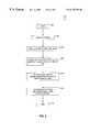
- FIG. 4is a flowchart illustrating the process of calibrating a reflection imaging spectrophotometer, according to an embodiment of the invention.
- FIG. 5illustrates a generic computer system which may be used to perform some of the operations required for calibration, according to an embodiment of the invention.
- the present inventionrepresents a system and method for calibrating a reflected spectral imaging apparatus, such as a reflection imaging spectrophotometer. Calibration is performed by inserting an optical filter into the light path of the spectrophotometer between the light source and the object being imaged.
- the filteris comprised of multiple areas which project corresponding areas on a focal plane at the object.
- the filteris fabricated such that the areas projected on the focal plane have different, known optical densities.
- the intensity of light returned from each of these areasis measured.
- the correspondence between the measured light intensity and the known optical density at each areais then used to calibrate the spectrophotometer.
- This calibration techniqueis particularly well-suited to reflection imaging spectrophotometry of living tissue.
- Calibration of a spectrophotometerrequires the use of two or more optical density standards as well as a standard reflecting surface, as discussed above.
- the use of physical standardsis not feasible when imaging living tissue below the surface. Insertion of such standards at the point where imaging is to take place would likely damage the tissue and, in the case of human tissue, injure the patient.
- control of the reflecting surfacefeasible in the case of living tissue.
- the present inventionprovides for calibration by using optically projected standards rather than physical ones, so that calibration of the spectrophotometer may be performed non-invasively, like the imaging process itself.
- the standard reflecting surfaceis that of the actual surface being imaged, so that the use of a separate standard reflecting surface is not necessary.
- a reflection image spectrophotometeris a non-invasive apparatus for analyzing physical matter.
- the spectrophotometercomprises means for illumination of an object to be imaged, such as a region of living human tissue, and for analysis of the light that is returned.
- Light which is returned from the objectwill have been affected by its interaction with the object.
- certain frequencies of the lightwill have been absorbed or attenuated.
- FIG. 1shows a block diagram illustrating one embodiment of a reflection image spectrophotometer used for non-invasive analysis of an object.
- Apparatus 100includes a light source 102 for illuminating an object under analysis, shown generally at 104 .
- a light source 102for illuminating an object under analysis, shown generally at 104 .
- each light sourcecan be monochromatic or polychromatic.
- Light source 102can be a light capable of being pulsed, or a non-pulsed light source providing continuous light, or one capable of either type of operation.
- Light source 102can include, for example, a pulsed xenon arc light, a mercury arc light, a halogen light, a tungsten light, a laser, a laser diode, or a light emitting diode (LED).
- Light source 102can be a source for coherent light, or a source for incoherent light.
- a first polarizer 110is placed between light source 102 and object under analysis 104 .
- a second polarizer or analyzer 120is placed in the reflected light path between object 104 and an image separating means 140 .
- Polarizers 110 and 120preferably have planes of polarization oriented 90° relative to each other.
- the light source and first polarizermay be combined so that a separate first polarizer 110 is not required.
- light source 102is a source of polarized light, for example, a laser or a laser diode
- second polarizer 120has a plane of polarization oriented 90° relative to the plane of polarization of polarized light source 102 .
- the output from the second polarizer 120is connected to image separating means 140 , which separates the image into two or more image portions.
- Each image portionis routed to an image capturing means, such as image capturing means 160 , 170 , and 165 .
- the output of each image capturing meansis coupled to an image correcting and analyzing means 180 .
- the output of the image correcting and analyzing means 180is connected to a display 190 .
- a more detailed illustration of such a reflection image spectrophotometeris presented in FIG. 2.
- a light path 202is formed between a light source 204 and an object 206 to be analyzed (such as living tissue), as directed by a beam splitter 208 .
- a reflected light path 210proceeds from object 206 to image capturing modules 212 and 214 .
- Suitable image capturing meansinclude, but are not limited to, a camera, a film medium, a charge coupled device (CCD) camera, or a complementary metallic oxide semiconductor (CMOS) camera.
- CCDcharge coupled device
- CMOScomplementary metallic oxide semiconductor
- a first polarizer 216is placed in light path 202 between light source 204 and object 206 .
- First polarizer 216has a plane of polarization indicated generally by an arrow 218 which is shown pointing into the plane of the figure.
- a second polarizer or analyzer 220is placed in reflected light path 210 between object 206 and image capturing modules 212 and 214 .
- Second polarizer 220has a plane of polarization shown generally at 222 . As shown in FIG. 2, planes of polarization 218 and 222 are oriented 90° relative to each other.
- Polarizers, such as polarizers 216 and 220having planes of polarization oriented 90° relative to each other, are referred to herein as “cross-polarizers”.
- Focusing lenses 224can be placed on either side of first polarizer 216 .
- a heat rejection filter 226is preferably placed in front of light source 204 .
- An objective lens 228is placed co-axially in light path 202 and reflected light path 210 .
- Image capturing modules 212 and 214are located in magnified image planes of objective lens 228 .
- An image separator 230is placed in reflected light path 210 between second polarizer 220 and image capturing means 212 , for separating the reflected image into a first portion 232 and a second portion 234 . It is to be understood that image separator 230 can separate the reflected image into a plurality of portions, and is not limited to two portions. First portion 232 of the reflected image is routed to first image capturing module 212 . Second portion 234 is routed to second image capturing module 214 . Second image capturing module 214 can be the same type of device as image capturing module 212 or it can be different. In alternative embodiments, additional image capturing modules can be used to capture further image portions separated by image separating module 230 . Alternatively, a single image capturing module can be used to capture both first portion 232 and second portion 234 of the reflected image.
- a spectral selector 236can be placed in reflected light path 210 between second polarizer 220 and image capturing means 212 .
- Spectral selector 236can be, for example, a monochromator, a spectral filter, prism, or grating.
- a spectral selector 238can be placed in reflected light path 210 between second polarizer 220 and second image capturing module 214 .
- Spectral selector 238can likewise be, for example, a monochromator, a spectral filter, prism, or grating.
- the center values for spectral selectors 236 and 238can be chosen based upon the type of analysis to be conducted.
- Image capturing module 212is coupled to an image correcting and analyzing module 240 .
- Image correcting and analyzing module 240can be a computer or other type of processing system (explained in more detail below with respect to FIG. 5 ).
- image capturing module 214is coupled to image correcting and analyzing module 240 .
- optical filter 242is placed in the light path 202 between light source 204 and object 206 for purposes of calibration of the reflection image spectrophotometer, and will be discussed in greater detail below.
- the optical filtermust be positioned in the path of the light, between the light source and the object under analysis.
- FIG. 2depicts an embodiment of the invention where an optical filter 242 is placed between heat rejection filter 226 and lenses 224 .
- the filtermay be placed elsewhere in the path between the light source and the object under analysis. The filter must, however, be placed so as to project a focused image within the object at the focal plane where imaging is to take place.
- Operation of the illustrated reflection imaging spectrophotometerbegins with the imaging of an object to produce a raw reflected image.
- Light originating from light source 204first travels along path 202 , where it passes through heat rejection filter 226 .
- the purpose of heat rejection filter 226is to block out infrared wavelengths.
- the lightthen passes through optical filter 242 so as to project an image, for purposes of calibration of the spectrophotometer, on the object under analysis 206 .
- This image for calibrationis described below in section VI.
- the light from light source 204then passes through focusing lenses 224 and first polarizer 216 .
- the lightis polarized in a first direction 218 by polarizer 216 .
- Polarized light from light source 204is then directed by beam splitter 208 through objective lens 228 , towards object 206 .
- the lightthen impinges on and is reflected from object 206 in direction 210 .
- the tissue covering the imaged portionshould be transparent and must be traversed by light to obtain a reflected image without multiple scattering.
- the reflected imageis essentially from a single scattering of the reflected light. In this manner, light from light source 204 penetrates the mucosal membrane to produce a raw reflected image of the microvascular system.
- the reflected imageis reflected from a depth less than the multiple scattering length, then passes through objective lens 228 , which magnifies the reflected image.
- the reflected lightcontains both polarized and unpolarized components.
- the Rayleigh scattering component of the reflected lightis unpolarized.
- the mirror reflection component and the rough surface scattering componentretain the polarization from polarizer 216 .
- second polarizer 220which is oriented in a direction 222 that is rotated 90° relative to first direction 218 , the mirror reflection component and the rough surface component are extinguished. Therefore, the only component of reflected light that passes through second polarizer 220 is the unpolarized Rayleigh scattering component.
- Rayleigh scatteringprovides a virtual backlighting effect that significantly increases the contrast and visualization of reflected images, and better enables the performance of quantitative analyses using reflected images.
- Image separator 230is placed in reflected light path 210 after second polarizer 220 for separating the reflected image into a first portion 232 and a second portion 234 .
- the portions 232 and 234then pass through spectral selectors 236 and 238 respectively.
- First portion 232 of the reflected imageis captured by first image capturing module 212 .
- Second portion 234is captured by second image capturing module 214 .
- Image capturing module 212is coupled to an image correcting and analyzing module 240 .
- a signal 262 representing the reflected image captured by image capturing module 212is sent by image capturing module 212 and received by image correcting and analyzing module 240 .
- image capturing module 214is coupled to image correcting and analyzing module 240 .
- a signal 272 representing the reflected image captured by image capturing module 214is sent by image capturing module 214 and received by image correcting and analyzing module 240 .
- Image correcting and analyzing module 240carries out the correction and analysis of the reflected image received, and can be a computer or other type of processing system (explained in more detail below with respect to FIG. 5 ). Image correcting and analyzing module 240 can be configured to carry out these steps through hardware, software, or a combination of hardware and software.
- image correcting and analyzing module 240may, in an embodiment of the invention, apply a correction function to the raw reflected image to normalize it with respect to the background.
- a poly-chromatic correctionsuch as a bi-chromatic correction
- a poly-chromatic correctioncan eliminate the effect of pigmentation of the tissue through which the light travels to illuminate the imaged portion of the vascular system. The tissue pigmentation will affect some wavelengths of light in the same manner, so that the tissue pigmentation effect is canceled out through use of a poly-chromatic correction.
- a velocity correctioncould be applied to extract moving cells from a stationary background. The velocity correction could be used alone, or in conjunction with, a polychromatic correction.
- Image correcting and analyzing module 240may also perform segmentation of an image.
- a sceneis segmented from the corrected reflected image to form an analysis image.
- the analysis imageis formed so that it contains the subject matter needed for analyzing a characteristic of object 206 .
- the characteristic to be analyzedmay be one for which large vessels should be analyzed, such as hemoglobin concentration per unit volume of blood, or the number of white blood cells per unit volume of blood. For these characteristics, the analysis image that contains large vessels is formed in part by the segmentation process.
- the characteristic to be analyzedmay be one for which small vessels should be analyzed, such as the number of platelets per unit volume of blood, or the concentration per unit volume of blood of components in capillary plasma, such as bilirubin. For these characteristics, the analysis image that contains small vessels is formed.
- the scenecan be segmented from the raw reflected image, and the scene then corrected to form the analysis image.
- the correction functionmay also be omitted entirely, so that the analysis image is formed from the raw reflected image.
- image correcting and analyzing module 240performs analysis of the analysis image with respect to one or more characteristics of the object 206 .
- the purpose of the present inventionis to allow calibration of the spectrophotometer so that analysis may be performed accurately.
- the spectrophotometermust be able to determine the exact optical density at specific points of the object under examination. It is this determination that permits quantitative analysis of cellular and chemical components of the blood in vivo.
- Optical densitymust be determined by measuring the intensity of light reflected from those points of the object under analysis. The light intensity measurement is used to the determine the optical density.
- the correlation between measured light intensity and optical densitymay differ from patient to patient and tissue to tissue.
- calibration of the spectrophotometermust first be performed. Such a calibration establishes the necessary correlation, i.e., the proper mapping between light intensity values and optical density values.
- the present inventionprovides a system and method for performing this mapping, by allowing the spectrophotometer to measure the light intensity emanating from areas of known optical density, i.e., the areas projected by the optical filter. Once intensity measurements are made and correlated to known optical densities at two or more points, then calibration can be performed.
- FIG. 3is an illustration of an image 300 projected by an optical filter that has been constructed according to an embodiment of the invention.
- Image 300comprises an annular ring 302 , a smaller concentric ring 304 , and a cross 306 .
- the optical filterhas been constructed so that ring 302 has an optical density of 1.00, ring 304 has an optical density of 0.50, and cross 306 has an optical density of 3.00.
- the optical filtermay be constructed so that the projected image contains areas having shapes and sizes other than what are portrayed in FIG.
- the projected areasmay have optical densities other than those portrayed in FIG. 3 .
- the optical filtermust be constructed so that projected areas of the image have two or more known optical densities. Construction of such a filter can be performed with conventional photolithographic techniques. Such techniques are well known to persons skilled in the relevant art. Moreover, optical filters similar to those described herein are readily available commercially.
- the optical filtermust be placed in the light path of the reflection image spectrophotometer in order to calibrate it.
- the optical filtermust be positioned in the path of the light, between the light source and the object under analysis.
- FIG. 2depicts an embodiment of the invention where optical filter 242 is placed between heat rejection filter 226 and lenses 224 .
- the filtermay be placed elsewhere in the path between the light source and the object under analysis. The filter must, however, be placed so as to project a focused image within the object at the focal plane where imaging is to take place.
- the optical filteris constructed so as to project an image that is optically neutral with respect to a plurality of wavelengths.
- the image from such a filterwill thus be composed of areas, each with an optical density that is constant for all such wavelengths. This results in a projected image that can be used to calibrate each of the channels of a bi-chromatic or multispectral reflection image spectrophotometer whose light source produces these wavelengths.
- the filtercan serve a secondary purpose, apart from calibration.
- a well-defined image projected by such a filtercan be used to align the images from two or more independent imaging channels. Such images may have been captured at different times, for example. This alignment is also known as registration.
- registrationBy registering the cross hairs on the respective independent images, precise superpositioning of such images is possible during analysis. Registration permits comparison of specific points or regions, so that differences or changes between the two images at those points may be identified.
- any filtermay serve this purpose if its image is well defined and if it projects two or more reference points so as to allow registration of multiple images.
- light originating from light source 204returns from object 206 under analysis (such as tissue) to image capturing devices 212 and 214 .
- object 206 under analysissuch as tissue
- the areas projected by optical filter 242 onto a focal plane of object 206also return light to image capturing devices 212 and 214 .
- the intensity of the light reflected from the projected areasis measured by image correction and analysis module 240 . For purposes of calibration, these measurements will ultimately be mapped to the known optical density values of the projected areas.
- Calibration of the spectrophotometerrequires that a plurality of measured light intensity values be correlated with known optical densities. Once the measured light intensity values are mapped to the corresponding optical densities, calibration may proceed.
- the light intensity measured for that areais mapped to the optical density value known for that area.
- the intensity of the light reflected from ring 302is recorded. This intensity is then mapped to an optical density of 1.00.
- the intensity of the light reflected from ring 304is mapped to an optical density of 0.50
- the intensity of the light reflected from cross 306is mapped to an optical density of 3.00.
- the associations between measured intensity values and known optical density valuesare then used to perform calibration.
- intensity measurementshave been taken at areas of the object under analysis where an image has been projected by an optical filter.
- the various areas of the projected imagehave known optical densities.
- the image correction/analysis module 240illustrated in FIG. 2, can now be calibrated, given that a plurality of intensity measurements are now known to correspond to specific optical densities.
- an optical filteris fabricated, having the properties described above in section II. Such a filter may be fabricated using known photolithographic methods that are well known to persons of ordinary skill in the relevant art.
- the filteris placed in the light path between the illumination source and the object (such as tissue) under analysis. The filter must be positioned so as to project a focused image at the plane in the object where imaging is to take place.
- the intensity of the light returned to the image correction and analysis moduleis measured.
- step 410for each area projected by an optical filter, the light intensity measured in step 408 for the area is mapped to the optical density known for that area.
- step 412the mapping established in step 410 is used to calibrate the image correction and analysis module of the spectrophotometer.
- optical filter creation(step 404 ), measurement of light intensity (step 408 ), mapping of measured light intensities to known optical densities (step 410 ), and use of this mapping for calibration (step 412 ) may be performed by hardware, software, human intervention, or some combination thereof.
- Computer system 500includes one or more processors, such as processor 504 .
- Processor 504is connected to a communication infrastructure 506 .
- Various software embodimentsare described in terms of this exemplary computer system. After reading this description, it will become apparent to a person skilled in the relevant art how to implement the invention using other computer systems and/or computer architectures.
- Computer system 500also includes a main memory 508 , preferably random access memory (RAM), and can also include a secondary memory 510 .
- Secondary memory 510can include, for example, a hard disk drive 512 and/or a removable storage drive 514 , representing a floppy disk drive, a magnetic tape drive, an optical disk drive, etc.
- Removable storage drive 514reads from and/or writes to a removable storage unit 518 in a well known manner.
- Removable storage unit 518represents a floppy disk, magnetic tape, optical disk, etc. which is read by and written to by removable storage drive 514 .
- removable storage unit 518includes a computer usable storage medium having stored therein computer software and/or data.
- secondary memory 510may include other similar means for allowing computer programs or other instructions to be loaded into computer system 500 .
- Such meanscan include, for example, a removable storage unit 522 and an interface 520 .
- Examples of suchcan include a program cartridge and cartridge interface (such as that found in video game devices), a removable memory chip (such as an EPROM, or PROM) and associated socket, and other removable storage units 522 and interfaces 520 which allow software and data to be transferred from removable storage unit 522 to computer system 500 .
- Computer system 500can also include a communications interface 524 .
- Communications interface 524allows software and data to be transferred between computer system 500 and external devices, such as image capturing means 212 and 214 .
- Examples of communications interface 524can include a modem, a network interface (such as an Ethernet card), a communications port, a PCMCIA slot and card, etc.
- Software and data transferred via communications interface 524are in the form of signals which can be electronic, electromagnetic, optical or other signals capable of being received by communications interface 524 .
- signals 262 and 272are provided to communications interface via a channel 528 .
- Channel 528carries signals 262 and 272 and can be implemented using wire or cable, fiber optics, a phone line, a cellular phone link, an RF link and other communications channels.
- computer program mediumand “computer usable medium” are used to generally refer to media such as removable storage device 518 , a hard disk installed in hard disk drive 512 , and signals provided via channel 528 .
- These computer program productsare means for providing software to computer system 500 .
- Computer programsare stored in main memory 508 and/or secondary memory 510 . Computer programs can also be received via communications interface 524 . Such computer programs, when executed, enable computer system 500 to perform the features of the present invention as discussed herein. In particular, the computer programs, when executed, enable processor 504 to perform the features of the present invention. Accordingly, such computer programs represent controllers of computer system 500 .
- the softwaremay be stored in a computer program product and loaded into computer system 500 using removable storage drive 514 , hard drive 512 or communications interface 524 .
- the control logicwhen executed by processor 504 , causes processor 504 to perform the functions of the invention as described herein.
- the inventionis implemented primarily in hardware using, for example, hardware components such as application specific integrated circuits (ASICs).
- ASICsapplication specific integrated circuits
Landscapes
- Physics & Mathematics (AREA)
- Spectroscopy & Molecular Physics (AREA)
- General Physics & Mathematics (AREA)
- Investigating Or Analysing Materials By Optical Means (AREA)
Abstract
Description
Claims (19)
Priority Applications (8)
| Application Number | Priority Date | Filing Date | Title |
|---|---|---|---|
| US09/271,993US6175750B1 (en) | 1999-03-19 | 1999-03-19 | System and method for calibrating a reflection imaging spectrophotometer |
| EP00917906AEP1169625A1 (en) | 1999-03-19 | 2000-03-15 | System and method for calibrating a reflection imaging spectrophotometer |
| HK02105090.6AHK1045187A1 (en) | 1999-03-19 | 2000-03-15 | System and method for calibrating a reflection imaging spectrophotometer |
| MXPA01009449AMXPA01009449A (en) | 1999-03-19 | 2000-03-15 | System and method for calibrating a reflection imaging spectrophotometer. |
| CA002366667ACA2366667A1 (en) | 1999-03-19 | 2000-03-15 | System and method for calibrating a reflection imaging spectrophotometer |
| AU38808/00AAU3880800A (en) | 1999-03-19 | 2000-03-15 | System and method for calibrating a reflection imaging spectrophotometer |
| JP2000606972AJP2002540391A (en) | 1999-03-19 | 2000-03-15 | System and method for calibrating a reflection imaging spectrophotometer |
| PCT/US2000/006587WO2000057146A1 (en) | 1999-03-19 | 2000-03-15 | System and method for calibrating a reflection imaging spectrophotometer |
Applications Claiming Priority (1)
| Application Number | Priority Date | Filing Date | Title |
|---|---|---|---|
| US09/271,993US6175750B1 (en) | 1999-03-19 | 1999-03-19 | System and method for calibrating a reflection imaging spectrophotometer |
Publications (1)
| Publication Number | Publication Date |
|---|---|
| US6175750B1true US6175750B1 (en) | 2001-01-16 |
Family
ID=23037951
Family Applications (1)
| Application Number | Title | Priority Date | Filing Date |
|---|---|---|---|
| US09/271,993Expired - LifetimeUS6175750B1 (en) | 1999-03-19 | 1999-03-19 | System and method for calibrating a reflection imaging spectrophotometer |
Country Status (8)
| Country | Link |
|---|---|
| US (1) | US6175750B1 (en) |
| EP (1) | EP1169625A1 (en) |
| JP (1) | JP2002540391A (en) |
| AU (1) | AU3880800A (en) |
| CA (1) | CA2366667A1 (en) |
| HK (1) | HK1045187A1 (en) |
| MX (1) | MXPA01009449A (en) |
| WO (1) | WO2000057146A1 (en) |
Cited By (23)
| Publication number | Priority date | Publication date | Assignee | Title |
|---|---|---|---|---|
| US20030151720A1 (en)* | 2002-02-11 | 2003-08-14 | Visx, Inc. | Apparatus and method for determining relative positional and rotational offsets between a first and second imaging device |
| US20030179929A1 (en)* | 2002-03-22 | 2003-09-25 | Unilever Home & Personal Care Usa, Division Of Conopco, Inc. | Cross-polarized imaging method for measuring skin ashing |
| US6717668B2 (en)* | 2000-03-07 | 2004-04-06 | Chemimage Corporation | Simultaneous imaging and spectroscopy apparatus |
| US20040159789A1 (en)* | 2000-10-13 | 2004-08-19 | Treado Patrick J. | Near infrared chemical imaging microscope |
| US6791676B1 (en)* | 1999-10-08 | 2004-09-14 | Dade Behring Marburg Gmbh | Spectrophotometric and nephelometric detection unit |
| US6898451B2 (en)* | 2001-03-21 | 2005-05-24 | Minformed, L.L.C. | Non-invasive blood analyte measuring system and method utilizing optical absorption |
| US20060001870A1 (en)* | 2004-06-30 | 2006-01-05 | Voigt Thomas C | System and method for dynamic chemical imaging |
| US20060082773A1 (en)* | 2004-10-14 | 2006-04-20 | The Procter & Gamble Company | Methods and apparatus for measuring an electromagnetic radiation response property associated with a substrate |
| US20060085274A1 (en)* | 2004-10-14 | 2006-04-20 | The Procter & Gamble Company | Methods and apparatus for selecting a color for use by a personal care product recommendation system |
| US20060082764A1 (en)* | 2004-10-14 | 2006-04-20 | The Procter & Gamble Company | Methods and apparatus for calibrating an electromagnetic measurement device |
| US20060098194A1 (en)* | 2004-11-08 | 2006-05-11 | David Tuschel | Method and apparatus for determining change in an attribute of a sample during nucleation, aggregation, or chemical interaction |
| US20060120566A1 (en)* | 2003-04-24 | 2006-06-08 | Toru Myogadani | Optical inspection device |
| US20060126062A1 (en)* | 2004-06-30 | 2006-06-15 | David Tuschel | Method and apparatus for producing a streaming raman image of nucleation, aggregation, and chemical interaction |
| US20060184037A1 (en)* | 2004-11-30 | 2006-08-17 | Can Ince | Pulsed lighting imaging systems and methods |
| US20070232874A1 (en)* | 2003-10-03 | 2007-10-04 | Can Ince | System and method for imaging the reflectance of a substrate |
| US7411672B2 (en) | 2004-06-30 | 2008-08-12 | Chemimage Corporation | Method and apparatus for chemical imaging in a microfluidic circuit |
| US7538872B1 (en)* | 2006-08-02 | 2009-05-26 | Butler Eugene W | Diagnostic methods and apparatus for directed energy applications |
| US20090294702A1 (en)* | 2008-05-29 | 2009-12-03 | Sony Corporation | Optical measuring instrument, and wavelength calibration method and optical measuring method for light detector |
| US20100070042A1 (en)* | 2000-08-08 | 2010-03-18 | Warsaw Orthopedic, Inc. | Implantable Joint Prosthesis |
| KR101078135B1 (en) | 2010-07-30 | 2011-10-28 | 경북대학교 산학협력단 | Full range calibration device of spectroscope for light source spectrum analysis and information acquisition method in the device |
| US20140093147A1 (en)* | 2010-04-30 | 2014-04-03 | Chemlmage Corporation | System and method for gross anatomic pathology using hyperspectral imaging |
| US9435741B2 (en) | 2010-08-30 | 2016-09-06 | Nanophoton Corporation | Spectrometry device and spectrometry method |
| US20170181670A1 (en)* | 2014-01-14 | 2017-06-29 | Analytics For Life | Noninvasive method for estimating glucose blood constituents |
Families Citing this family (2)
| Publication number | Priority date | Publication date | Assignee | Title |
|---|---|---|---|---|
| DE102009043751B4 (en) | 2009-09-30 | 2024-05-23 | Carl Zeiss Meditec Ag | Method for calibrating an ophthalmic laser system and laser system |
| CN103017901B (en)* | 2012-11-21 | 2014-07-30 | 南京邮电大学 | Spectral measurement method and micro spectrograph based on varifocus lens |
Citations (8)
| Publication number | Priority date | Publication date | Assignee | Title |
|---|---|---|---|---|
| EP0444689A2 (en) | 1990-03-01 | 1991-09-04 | X-Rite, Inc. | A compensation method adapted for use in color measuring apparatus |
| EP0529530A2 (en) | 1991-08-23 | 1993-03-03 | Eastman Kodak Company | A method of calibrating a multichannel printer |
| EP0570003A2 (en) | 1992-05-15 | 1993-11-18 | Toyota Jidosha Kabushiki Kaisha | Rendering apparatus, multispectral image scanner, and three-dimensional automatic gonio-spectrophotometer |
| US5321970A (en) | 1990-09-18 | 1994-06-21 | Davies Anthony M C | Method and apparatus for calibrating a spectrometer |
| US5565678A (en)* | 1995-06-06 | 1996-10-15 | Lumisys, Inc. | Radiographic image quality assessment utilizing a stepped calibration target |
| US5592290A (en)* | 1993-11-12 | 1997-01-07 | Fuji Photo Film Co., Ltd. | Method for correcting instrumental error of spectroscope of optical analyzer |
| US5838435A (en) | 1997-10-20 | 1998-11-17 | Sandia Corporation | Calibration method for spectroscopic systems |
| US5905808A (en)* | 1997-03-13 | 1999-05-18 | Ortho Diagnostic Systems, Inc. | Method and apparatus for calibrating imaging systems for analyzing agglutination reactions |
- 1999
- 1999-03-19USUS09/271,993patent/US6175750B1/ennot_activeExpired - Lifetime
- 2000
- 2000-03-15CACA002366667Apatent/CA2366667A1/ennot_activeAbandoned
- 2000-03-15EPEP00917906Apatent/EP1169625A1/ennot_activeWithdrawn
- 2000-03-15MXMXPA01009449Apatent/MXPA01009449A/enunknown
- 2000-03-15WOPCT/US2000/006587patent/WO2000057146A1/ennot_activeApplication Discontinuation
- 2000-03-15HKHK02105090.6Apatent/HK1045187A1/enunknown
- 2000-03-15JPJP2000606972Apatent/JP2002540391A/enactivePending
- 2000-03-15AUAU38808/00Apatent/AU3880800A/ennot_activeAbandoned
Patent Citations (8)
| Publication number | Priority date | Publication date | Assignee | Title |
|---|---|---|---|---|
| EP0444689A2 (en) | 1990-03-01 | 1991-09-04 | X-Rite, Inc. | A compensation method adapted for use in color measuring apparatus |
| US5321970A (en) | 1990-09-18 | 1994-06-21 | Davies Anthony M C | Method and apparatus for calibrating a spectrometer |
| EP0529530A2 (en) | 1991-08-23 | 1993-03-03 | Eastman Kodak Company | A method of calibrating a multichannel printer |
| EP0570003A2 (en) | 1992-05-15 | 1993-11-18 | Toyota Jidosha Kabushiki Kaisha | Rendering apparatus, multispectral image scanner, and three-dimensional automatic gonio-spectrophotometer |
| US5592290A (en)* | 1993-11-12 | 1997-01-07 | Fuji Photo Film Co., Ltd. | Method for correcting instrumental error of spectroscope of optical analyzer |
| US5565678A (en)* | 1995-06-06 | 1996-10-15 | Lumisys, Inc. | Radiographic image quality assessment utilizing a stepped calibration target |
| US5905808A (en)* | 1997-03-13 | 1999-05-18 | Ortho Diagnostic Systems, Inc. | Method and apparatus for calibrating imaging systems for analyzing agglutination reactions |
| US5838435A (en) | 1997-10-20 | 1998-11-17 | Sandia Corporation | Calibration method for spectroscopic systems |
Cited By (55)
| Publication number | Priority date | Publication date | Assignee | Title |
|---|---|---|---|---|
| US6791676B1 (en)* | 1999-10-08 | 2004-09-14 | Dade Behring Marburg Gmbh | Spectrophotometric and nephelometric detection unit |
| US6717668B2 (en)* | 2000-03-07 | 2004-04-06 | Chemimage Corporation | Simultaneous imaging and spectroscopy apparatus |
| US20100070042A1 (en)* | 2000-08-08 | 2010-03-18 | Warsaw Orthopedic, Inc. | Implantable Joint Prosthesis |
| US20060192956A1 (en)* | 2000-10-13 | 2006-08-31 | Chemimage Corp | Near infrared chemical imaging microscope |
| US7436500B2 (en) | 2000-10-13 | 2008-10-14 | Chemimage Corporation | Near infrared chemical imaging microscope |
| US7061606B2 (en) | 2000-10-13 | 2006-06-13 | Chem Image Corporation | Near infrared chemical imaging microscope |
| US7268861B2 (en) | 2000-10-13 | 2007-09-11 | Chemimage Corporation | Near infrared chemical imaging microscope |
| US7019296B2 (en) | 2000-10-13 | 2006-03-28 | Chemimage Corporation | Near infrared chemical imaging microscope |
| US7317516B2 (en) | 2000-10-13 | 2008-01-08 | Chemimage Corporation | Near infrared chemical imaging microscope |
| US7268862B2 (en) | 2000-10-13 | 2007-09-11 | Chem Image Corporation | Near infrared chemical imaging microscope |
| US20060164640A1 (en)* | 2000-10-13 | 2006-07-27 | Chem Image Corporation | Near infrared chemical imaging microscope |
| USRE39977E1 (en) | 2000-10-13 | 2008-01-01 | Chemimage Corporation | Near infrared chemical imaging microscope |
| US20040159789A1 (en)* | 2000-10-13 | 2004-08-19 | Treado Patrick J. | Near infrared chemical imaging microscope |
| US20060151702A1 (en)* | 2000-10-13 | 2006-07-13 | Chemimagie Corporation | Near infrared chemical imaging microscope |
| US7123360B2 (en) | 2000-10-13 | 2006-10-17 | Chemimage Corporation | Near infrared chemical imaging microscope |
| US20060157652A1 (en)* | 2000-10-13 | 2006-07-20 | Chemimage Corporation | Near infrared chemical imaging microscope |
| US7068357B2 (en) | 2000-10-13 | 2006-06-27 | Chemimage Corporation | Near infrared chemical imaging microscope |
| US6898451B2 (en)* | 2001-03-21 | 2005-05-24 | Minformed, L.L.C. | Non-invasive blood analyte measuring system and method utilizing optical absorption |
| US20030151720A1 (en)* | 2002-02-11 | 2003-08-14 | Visx, Inc. | Apparatus and method for determining relative positional and rotational offsets between a first and second imaging device |
| CN100450427C (en)* | 2002-02-11 | 2009-01-14 | 维思克斯公司 | Determining relative positional and rotational offsets |
| US7040759B2 (en)* | 2002-02-11 | 2006-05-09 | Visx, Incorporated | Apparatus and method for determining relative positional and rotational offsets between a first and second imaging device |
| US7024037B2 (en)* | 2002-03-22 | 2006-04-04 | Unilever Home & Personal Care Usa, A Division Of Conopco, Inc. | Cross-polarized imaging method for measuring skin ashing |
| US20030179929A1 (en)* | 2002-03-22 | 2003-09-25 | Unilever Home & Personal Care Usa, Division Of Conopco, Inc. | Cross-polarized imaging method for measuring skin ashing |
| US20060120566A1 (en)* | 2003-04-24 | 2006-06-08 | Toru Myogadani | Optical inspection device |
| US8064976B2 (en) | 2003-10-03 | 2011-11-22 | Can Ince | Systems and methods for sidesstream dark field imaging |
| US8452384B2 (en) | 2003-10-03 | 2013-05-28 | MicroVision Medical Holdings B.V. | Systems and methods for sidesstream dark field imaging |
| US20070232874A1 (en)* | 2003-10-03 | 2007-10-04 | Can Ince | System and method for imaging the reflectance of a substrate |
| US20060126062A1 (en)* | 2004-06-30 | 2006-06-15 | David Tuschel | Method and apparatus for producing a streaming raman image of nucleation, aggregation, and chemical interaction |
| US7046359B2 (en) | 2004-06-30 | 2006-05-16 | Chemimage Corporation | System and method for dynamic chemical imaging |
| US7580126B2 (en) | 2004-06-30 | 2009-08-25 | Chemimage Corp. | Method and apparatus for producing a streaming Raman image of nucleation, aggregation, and chemical interaction |
| US20060268267A1 (en)* | 2004-06-30 | 2006-11-30 | Chem Image Corporation | System and method for dynamic chemical imaging |
| US20060001870A1 (en)* | 2004-06-30 | 2006-01-05 | Voigt Thomas C | System and method for dynamic chemical imaging |
| US7411672B2 (en) | 2004-06-30 | 2008-08-12 | Chemimage Corporation | Method and apparatus for chemical imaging in a microfluidic circuit |
| US7317526B2 (en) | 2004-06-30 | 2008-01-08 | Chem Image Corporation | System and method for dynamic chemical imaging |
| WO2006044560A1 (en)* | 2004-10-14 | 2006-04-27 | The Procter & Gamble Company | Methods and apparatus for calibrating an electromagnetic measurement device |
| US20060082764A1 (en)* | 2004-10-14 | 2006-04-20 | The Procter & Gamble Company | Methods and apparatus for calibrating an electromagnetic measurement device |
| US7274453B2 (en) | 2004-10-14 | 2007-09-25 | The Procter & Gamble Company | Methods and apparatus for calibrating an electromagnetic measurement device |
| US7193712B2 (en) | 2004-10-14 | 2007-03-20 | The Procter & Gamble Company | Methods and apparatus for measuring an electromagnetic radiation response property associated with a substrate |
| US20060082773A1 (en)* | 2004-10-14 | 2006-04-20 | The Procter & Gamble Company | Methods and apparatus for measuring an electromagnetic radiation response property associated with a substrate |
| US20060085274A1 (en)* | 2004-10-14 | 2006-04-20 | The Procter & Gamble Company | Methods and apparatus for selecting a color for use by a personal care product recommendation system |
| US20080059218A1 (en)* | 2004-10-14 | 2008-03-06 | Sottery John P | Methods and systems for recommending a personal care product |
| US20090161101A1 (en)* | 2004-11-08 | 2009-06-25 | Chemimage Corporation | Method and apparatus for determining change in an attribute of a sample during nucleation, aggregation, or chemical interaction |
| US20060098194A1 (en)* | 2004-11-08 | 2006-05-11 | David Tuschel | Method and apparatus for determining change in an attribute of a sample during nucleation, aggregation, or chemical interaction |
| US20060184037A1 (en)* | 2004-11-30 | 2006-08-17 | Can Ince | Pulsed lighting imaging systems and methods |
| US9131861B2 (en) | 2004-11-30 | 2015-09-15 | Academisch Medisch Centrum | Pulsed lighting imaging systems and methods |
| US7538872B1 (en)* | 2006-08-02 | 2009-05-26 | Butler Eugene W | Diagnostic methods and apparatus for directed energy applications |
| US8263956B2 (en) | 2008-05-29 | 2012-09-11 | Sony Corporation | Optical flow channel measuring instrument |
| US20090294702A1 (en)* | 2008-05-29 | 2009-12-03 | Sony Corporation | Optical measuring instrument, and wavelength calibration method and optical measuring method for light detector |
| US20140093147A1 (en)* | 2010-04-30 | 2014-04-03 | Chemlmage Corporation | System and method for gross anatomic pathology using hyperspectral imaging |
| US9274046B2 (en)* | 2010-04-30 | 2016-03-01 | Chemimage Corporation | System and method for gross anatomic pathology using hyperspectral imaging |
| WO2012015264A3 (en)* | 2010-07-30 | 2012-05-18 | 경북대학교 산학협력단 | Full-range calibration apparatus for a spectrometer for analysis of the light spectrum, and method for acquiring information using the apparatus |
| KR101078135B1 (en) | 2010-07-30 | 2011-10-28 | 경북대학교 산학협력단 | Full range calibration device of spectroscope for light source spectrum analysis and information acquisition method in the device |
| US9435741B2 (en) | 2010-08-30 | 2016-09-06 | Nanophoton Corporation | Spectrometry device and spectrometry method |
| US20170181670A1 (en)* | 2014-01-14 | 2017-06-29 | Analytics For Life | Noninvasive method for estimating glucose blood constituents |
| US10765350B2 (en)* | 2014-01-14 | 2020-09-08 | Analytics For Life Inc. | Noninvasive method for estimating glucose blood constituents |
Also Published As
| Publication number | Publication date |
|---|---|
| CA2366667A1 (en) | 2000-09-28 |
| HK1045187A1 (en) | 2002-11-15 |
| WO2000057146A1 (en) | 2000-09-28 |
| AU3880800A (en) | 2000-10-09 |
| MXPA01009449A (en) | 2002-05-14 |
| WO2000057146A9 (en) | 2002-02-14 |
| EP1169625A1 (en) | 2002-01-09 |
| JP2002540391A (en) | 2002-11-26 |
Similar Documents
| Publication | Publication Date | Title |
|---|---|---|
| US6175750B1 (en) | System and method for calibrating a reflection imaging spectrophotometer | |
| TWI693391B (en) | Imaging device and method | |
| US6438396B1 (en) | Method and apparatus for providing high contrast imaging | |
| US5722398A (en) | Apparatus for measuring concentration of hemoglobin and method for the same | |
| US8126205B2 (en) | Sample imaging and classification | |
| US7224468B2 (en) | En-face functional imaging using multiple wavelengths | |
| US8315692B2 (en) | Multi-spectral imaging spectrometer for early detection of skin cancer | |
| US9095255B2 (en) | Method and device for locating function-supporting tissue areas in a tissue region | |
| JP7121892B2 (en) | Optical modules and optical devices | |
| WO2023007011A1 (en) | Photonic integrated circuit | |
| EP2691759B1 (en) | High flux collimated illuminator and method of uniform field illumination | |
| JPS60246733A (en) | Optical photographing apparatus of organism tissue | |
| JP2014517271A5 (en) | ||
| US20070276260A1 (en) | Method For Measuring The Vessel Diameter Of Optically Accessible Blood Vessels | |
| JP6587959B2 (en) | Skin image generation device, method of operating skin image generation device, and skin image generation processing program | |
| WO2021118805A1 (en) | Virtual hyperspectral imaging of biological tissue for blood hemoglobin analysis | |
| JP2000325295A (en) | Method and device for outputting fluorescent diagnostic information | |
| JP7603696B2 (en) | DETECTION APPARATUS AND DETECTION METHOD | |
| US20240331200A1 (en) | Endoscope device, endoscopic medical assistance system and endoscopic image processing method | |
| JPH03254727A (en) | Image photographing device | |
| JP3447877B2 (en) | Density measurement optical system | |
| JPS61107482A (en) | Photographing device of biological tissue | |
| JPS6291802A (en) | Observation measurement device |
Legal Events
| Date | Code | Title | Description |
|---|---|---|---|
| AS | Assignment | Owner name:CYTOMETRICS, INC., PENNSYLVANIA Free format text:ASSIGNMENT OF ASSIGNORS INTEREST;ASSIGNORS:COOK, CHRISTOPHER A.;GRONER, WARREN;NADEAU, RICHARD G.;REEL/FRAME:009848/0562;SIGNING DATES FROM 19990311 TO 19990316 | |
| STCF | Information on status: patent grant | Free format text:PATENTED CASE | |
| AS | Assignment | Owner name:RHEOLOGICS, INC., PENNSYLVANIA Free format text:ASSIGNMENT OF ASSIGNORS INTEREST;ASSIGNOR:CLAYBROOK, MONTAGUE;REEL/FRAME:012865/0677 Effective date:20011203 | |
| AS | Assignment | Owner name:CYTOMETRICS LLC, PENNSYLVANIA Free format text:ASSIGNMENT OF ASSIGNORS INTEREST;ASSIGNOR:RHEOLOGICS INC.;REEL/FRAME:012958/0392 Effective date:20020530 | |
| AS | Assignment | Owner name:CYTOPROP, LLC, PENNSYLVANIA Free format text:ASSIGNMENT OF ASSIGNORS INTEREST;ASSIGNOR:CYTOMETRICS, LLC;REEL/FRAME:013634/0029 Effective date:20021219 | |
| FEPP | Fee payment procedure | Free format text:PAYOR NUMBER ASSIGNED (ORIGINAL EVENT CODE: ASPN); ENTITY STATUS OF PATENT OWNER: SMALL ENTITY | |
| FPAY | Fee payment | Year of fee payment:4 | |
| AS | Assignment | Owner name:CYTOMETRICS, LLC, PENNSYLVANIA Free format text:SECURITY AGREEMENT;ASSIGNOR:INTELLIGENT MEDICAL DEVICES, INC.;REEL/FRAME:015418/0598 Effective date:20041202 | |
| AS | Assignment | Owner name:INTELLIGENT MEDICAL DEVICES, INC., MASSACHUSETTS Free format text:ASSIGNMENT OF ASSIGNORS INTEREST;ASSIGNOR:CYTOPROP, LLC;REEL/FRAME:015861/0320 Effective date:20041202 | |
| FEPP | Fee payment procedure | Free format text:PAYER NUMBER DE-ASSIGNED (ORIGINAL EVENT CODE: RMPN); ENTITY STATUS OF PATENT OWNER: SMALL ENTITY | |
| FPAY | Fee payment | Year of fee payment:8 | |
| AS | Assignment | Owner name:INTELLECTUAL PROPERTY MVM B.V., NETHERLANDS Free format text:ASSIGNMENT OF ASSIGNORS INTEREST;ASSIGNORS:WILMINGTON TRUST COMPANY;RHEOLOGICS, INC.;CYTOMETRICS, LLC;AND OTHERS;REEL/FRAME:020845/0408;SIGNING DATES FROM 20080225 TO 20080312 | |
| AS | Assignment | Owner name:INTELLIGENT MEDICAL DEVICES, INC., MASSACHUSETTS Free format text:RELEASE BY SECURED PARTY;ASSIGNOR:WILMINGTON TRUST COMPANY;REEL/FRAME:020876/0338 Effective date:20080304 | |
| FEPP | Fee payment procedure | Free format text:PAYOR NUMBER ASSIGNED (ORIGINAL EVENT CODE: ASPN); ENTITY STATUS OF PATENT OWNER: SMALL ENTITY | |
| FPAY | Fee payment | Year of fee payment:12 |