US6175688B1 - Wearable intravenous fluid heater - Google Patents
Wearable intravenous fluid heaterDownload PDFInfo
- Publication number
- US6175688B1 US6175688B1US09/113,255US11325598AUS6175688B1US 6175688 B1US6175688 B1US 6175688B1US 11325598 AUS11325598 AUS 11325598AUS 6175688 B1US6175688 B1US 6175688B1
- Authority
- US
- United States
- Prior art keywords
- fluid
- temperature
- heating
- flow path
- heating element
- Prior art date
- Legal status (The legal status is an assumption and is not a legal conclusion. Google has not performed a legal analysis and makes no representation as to the accuracy of the status listed.)
- Expired - Lifetime
Links
Images


Classifications
- A—HUMAN NECESSITIES
- A61—MEDICAL OR VETERINARY SCIENCE; HYGIENE
- A61M—DEVICES FOR INTRODUCING MEDIA INTO, OR ONTO, THE BODY; DEVICES FOR TRANSDUCING BODY MEDIA OR FOR TAKING MEDIA FROM THE BODY; DEVICES FOR PRODUCING OR ENDING SLEEP OR STUPOR
- A61M5/00—Devices for bringing media into the body in a subcutaneous, intra-vascular or intramuscular way; Accessories therefor, e.g. filling or cleaning devices, arm-rests
- A61M5/44—Devices for bringing media into the body in a subcutaneous, intra-vascular or intramuscular way; Accessories therefor, e.g. filling or cleaning devices, arm-rests having means for cooling or heating the devices or media
- A—HUMAN NECESSITIES
- A61—MEDICAL OR VETERINARY SCIENCE; HYGIENE
- A61M—DEVICES FOR INTRODUCING MEDIA INTO, OR ONTO, THE BODY; DEVICES FOR TRANSDUCING BODY MEDIA OR FOR TAKING MEDIA FROM THE BODY; DEVICES FOR PRODUCING OR ENDING SLEEP OR STUPOR
- A61M5/00—Devices for bringing media into the body in a subcutaneous, intra-vascular or intramuscular way; Accessories therefor, e.g. filling or cleaning devices, arm-rests
- A61M5/36—Devices for bringing media into the body in a subcutaneous, intra-vascular or intramuscular way; Accessories therefor, e.g. filling or cleaning devices, arm-rests with means for eliminating or preventing injection or infusion of air into body
- A61M5/365—Air detectors
- A—HUMAN NECESSITIES
- A61—MEDICAL OR VETERINARY SCIENCE; HYGIENE
- A61M—DEVICES FOR INTRODUCING MEDIA INTO, OR ONTO, THE BODY; DEVICES FOR TRANSDUCING BODY MEDIA OR FOR TAKING MEDIA FROM THE BODY; DEVICES FOR PRODUCING OR ENDING SLEEP OR STUPOR
- A61M2205/00—General characteristics of the apparatus
- A61M2205/33—Controlling, regulating or measuring
- A61M2205/3331—Pressure; Flow
- A—HUMAN NECESSITIES
- A61—MEDICAL OR VETERINARY SCIENCE; HYGIENE
- A61M—DEVICES FOR INTRODUCING MEDIA INTO, OR ONTO, THE BODY; DEVICES FOR TRANSDUCING BODY MEDIA OR FOR TAKING MEDIA FROM THE BODY; DEVICES FOR PRODUCING OR ENDING SLEEP OR STUPOR
- A61M5/00—Devices for bringing media into the body in a subcutaneous, intra-vascular or intramuscular way; Accessories therefor, e.g. filling or cleaning devices, arm-rests
- A61M5/14—Infusion devices, e.g. infusing by gravity; Blood infusion; Accessories therefor
- A61M5/168—Means for controlling media flow to the body or for metering media to the body, e.g. drip meters, counters ; Monitoring media flow to the body
- A61M5/16886—Means for controlling media flow to the body or for metering media to the body, e.g. drip meters, counters ; Monitoring media flow to the body for measuring fluid flow rate, i.e. flowmeters
Definitions
- the present inventionrelates generally to a device for heating to a desired infusion temperature a fluid to be supplied intravenously to a patient. More specifically, it relates to such a device that is (1) dimensioned to be wearable on the patient adjacent to the infusion situs (i.e., the location on the patient's body were the fluid is to be infused into the patient), and (2) configured to determine automatically when, and to provide warning if, the fluid flow rate in the device falls below a desired minimum threshold therefor, and/or gas (e.g., air) is present in the fluid.
- gase.g., air
- the present inventionfinds particular utility in heating of fluids which are to be supplied intravenously at relatively low flow rates (e.g., below about 2550 ml/hour for fluids to be heated to an infusion temperature of between 38-42 degrees C. from an input temperature into the device of 10 degrees C., or below about 3600 ml/hour for fluids to be heated to such an infusion temperature from an input temperature of 18 degrees C.), it should be understood that other utilities are also contemplated for the present invention (e.g., infusion of intravenous fluids at other temperatures and flow rates).
- the '693 patentis directed to an intravenous fluid heater that includes a disposable cassette containing a heat exchanger.
- the preferred embodiment of the heat exchanger disclosed in the '693 patentincludes a passageway-defining inner layer sandwiched between a pair of flexible, metal foil membranes.
- the inner layerdefines an extended, e.g., serpentine, path for fluid to be warmed, and serves to space apart and insulate the metal foil membranes from one another. Inlet and outlet ports to the serpentine fluid path are defined in one of the two foil membranes.
- Heat generated by heating elements which sandwich the heat exchangeris transferred through the metal foil membranes to the fluid flowing through the serpentine path.
- the heating elementsare designed to be graduated, that is, to generate more heat in the area of the inlet portion of the serpentine path than in the area of its outlet.
- the heating device disclosed in the '693 patentsuffers from several disadvantages.
- the heating elements of the '693 deviceapply non-uniform, graduated heating to the fluid traversing the flow path, the risk exists that, depending upon the fluid flow rate through the flow path, the fluid may become overheated (i.e., heated above the desired target temperature for infusion) at the portion of the heating elements applying elevated amounts of heat to the fluid. If sufficiently elevated, such overheating can damage certain types of intravenously delivered fluids (e.g., blood and blood-products, if the overheating is above about 41 degrees C.).
- intravenously delivered fluidse.g., blood and blood-products, if the overheating is above about 41 degrees C.
- the heating device disclosed in the '693 patentis not wearable by the patient adjacent the fluid infusion situs.
- the length of tubing required to deliver the heated fluid from the device to the infusion situsmay vary depending upon where the device is positioned relative to the patient, but will always be longer than that which would be required if the device were being worn by the patient at or near the infusion situs.
- the temperature of the heated fluid exiting the heating devicewill always drop, prior to being infused into the patient, more than would be the case if the heating device were wearable adjacent the infusion situs.
- the temperature drop of the heated fluidcan be especially pronounced at the aforesaid relatively low fluid flow rates. Unfortunately, a significant proportion of intravenous fluid infusions take place at such low flow rates.
- a yet further disadvantage of the '693 patent's heating arrangementis that although means are included for reducing gas bubble formation in the infusion fluid, no means are provided for automatically determining whether such bubbles are present in the fluid or whether there has been reduction in fluid flow rate, and for taking appropriate action (e.g., providing warning and/or stopping fluid flow into the patient) in the event such conditions are determined to be present.
- appropriate actione.g., providing warning and/or stopping fluid flow into the patient
- U.S. Pat. No. 5,254,094Another conventional infusion fluid warming device is disclosed in U.S. Pat. No. 5,254,094 (“the '094 patent”).
- a boxwhich may be attached to a patient's arm is provided.
- Two chambersare included in the box, containing a heat exchanger element constructed from a continuous length of stainless steel tubing in the form of two parallel coils which are connected to each other by a straight length of tubing.
- the boxincludes a passage between the chambers such that a warming fluid may be introduced through an aperture in the box into one of the chambers, flow into the other chamber, and then exit the warmer through another aperture in the box.
- the infusion fluid to be warmedis supplied to the coils through a first flexible plastic inlet tube and discharged for infusion into a patient through a second flexible plastic tube.
- the warming fluidis supplied via fluid supply tubing to the box from a separate fluid source that is not dimensioned or suitable for being worn by the patient, such as a water heater.
- a temperature sensor located in the infusion fluid path between the box and the infusion situsmay be provided for generating signals indicative of the temperature of the infusion fluid for provision to a microprocessor contained in the same unit comprising the water heater.
- the microprocessoralso receives outputs from a water temperature sensor and controls the water heater, based upon the outputs from these sensors and a desired infusion fluid temperature set by the user, so as to maintain the heating water at a temperature for heating the infusion fluid to the desired temperature.
- the '094 patentdiscloses no means for automatically determining whether gas bubbles are present in the infusion fluid or there has been reduction in infusion fluid flow rate, and for taking appropriate action (e.g., providing warning and/or stopping fluid flow into the patient) in event such conditions are determined to be present.
- an intravenous fluid heateris provided that is dimensioned to be wearable adjacent a patient's intravenous fluid infusion situs.
- the heaterincludes a heat exchanger for defining a flow path through the heater for fluid to be infused via the infusion situs.
- At least one controllable heating elementis provided for heating the fluid in the flow path by heat conduction thereto through the heat exchanger.
- Sensorsare included in the heater for sensing respective temperatures of entering and exiting fluids of the flow path.
- a controllercontrols, based upon at least one of the entering and exiting fluid temperatures, heating of the fluid in the flow path by the heating element.
- the fluid in the flow pathis substantially uniformly heated to a desired infusion temperature prior to exiting the heater.
- the controllermay be programmed to determine, based at least in part upon one or both of the entering/exiting fluid temperatures, whether the flow rate of fluid is below a desired threshold value therefor, and/or whether gas is present in the flow path.
- the controllermay also be programmed to initiate provision of a warning/indication to a user of the device, and/or to initiate other appropriate action (e.g., closing a valve in the device to prevent further flow of fluid to the patient), when one or both of the aforesaid conditions are present.
- the at least one heating elementmay include two heating elements, and the heat exchanger may include two flexible walls for contacting a member inserted between the flexible sheets for defining together with the flexible sheets the flow path.
- the flexible wallsare preferably made of plastic.
- use of these plastic wallspermit this embodiment of the present invention to overcome the aforesaid disadvantages that result from use of the metal foil membranes in the '693 patent's heating device.
- the device of this embodiment of the present inventionmay also include an electrically insulating external housing and disposable cover for enclosing the aforesaid components of the device so as to prevent contamination of same and risk of electric shock injury to the patient wearing the device.
- the heat exchangermay be unattached to the remainder of the device and may be held in place in the device by forces applied to the exchanger by the mechanism used to lock the housing in place about the other components of the device.
- thispermits both the cover and heat exchanger to be disposable/replaceable, and the remainder of the device to be reusable.
- the heating elementmay include at least one metal plate for contacting the heat exchanger and an electrical resistance heater, controlled by the controller, for controllably heating the plate.
- the electrical resistance heatermay include a printed circuit board etched metal layer.
- a thermally conductive, electrically insulating layermay be positioned between the etched metal layer and plate.
- the controller, sensors, and metal layermay all be part of a single, double-sided circuit board.
- the entire intravenous fluid heateri.e., the heat exchanger, heating element(s), sensors, controller, etc.
- the controllermay be programmed to detect presence of reduced fluid flow and/or air in the fluid flow, and to warn and/or prevent further supply of the fluid upon detection of conditions.
- the heating elementsare completely solid, and no warming fluid is used to heat the infusion fluid.
- FIG. 1is an outside perspective view of one embodiment of the intravenous fluid heater of present invention, wherein the strap mechanism for fastening the heater to the patient has been removed for purposes of clarity of illustration.
- FIG. 2is an exploded perspective view of the disposable heat exchanger of the embodiment of FIG. 1 .
- FIG. 3is a perspective view of the portion of the disposable heat exchanger of FIG. 2 that defines a serpentine flow path for the infusion fluid.
- FIG. 4is a cross-sectional view taken along lines 4 — 4 of FIG. 3 .
- FIG. 5is a highly schematic, partial cross-sectional view taken along lines 5 — 5 of FIG. 1 for illustrating, in a general fashion, the layered construction of the embodiment of FIG. 1 .
- FIG. 6is an exploded, schematic view illustrating the construction of the embodiment of FIG. 1, with the heat exchanger of FIG. 2 and the top indicator plate removed.
- FIG. 7is a highly schematic, functional block diagram of the electronics used in the embodiment of FIG. 1 .
- FIG. 8illustrates the electrically conductive etchings used to heat the infusion fluid in the embodiment of FIG. 1 .
- FIG. 9is a flowchart of the fluid temperature measurement method used in the embodiment of FIG. 1 .
- FIG. 10is a flowchart of one fluid heating control method that can be used in the embodiment of FIG. 1 .
- FIG. 11is a flowchart of another fluid heating control method that can be used in the embodiment of FIG. 1 .
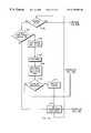
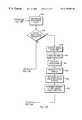
- FIGS. 12A and 12Bare flowcharts of a process used in the embodiment of FIG. 1 to determine whether gas is present in, and/or fluid flow rate through the heat exchanger's fluid flow path is below a desired minimum value therefor.
- FIG. 13is an outside perspective view of a variation of the embodiment of FIG. 1, which variation includes a controllable valve for stopping fluid flow through the heater if gas is present in and/or fluid flow through the heat exchanger is below a desired minimum therefor.
- FIG. 14is a highly schematic functional block diagram of electronics of the controllable valve system used in the variation of FIG. 13 .
- FIG. 15shows the embodiment of FIG. 1 in use, being worn by a patient and delivering heated infusion fluid to the patient's infusion situs.
- FIG. 16is a schematic representation of the piston, tube choke channel, and memory wire actuator of the valve system of the variation of FIG. 13 .
- FIGS. 1 - 12 A and 12 B and 15depict one preferred embodiment 10 of the wearable infusion fluid heater of the present invention.
- Heater 10comprises a hard plastic housing 12 in the form of two generally square-shaped members 24 , 26 joined via a locking hinge mechanism 36 .
- Hinge mechanism 36comprises an upper hinge portion 37 and mating lower hinge portion 39 .
- These hinge portions 37 , 39are pivotably connected to each other via conventional means (e.g., a bolt, screw, or similar means, not shown) fastened into the common opening through the portions 37 , 39 formed when the portions 37 , 39 are mated with each other and the respective openings 41 , 43 of the portions 37 , 39 are in coaxial alignment with each other. Openings 41 , 43 extend longitudinally through the hinge portions 37 , 39 .
- a rectangular indicator face plate 14is slightly undersized relative to rectangular recessed area 57 of top plate 26 and is attached there at via conventional means (e.g., glue or other type of bonding material) to the top plate 26 .
- Indicator plate 14includes a plurality of openings (collectively referred to by numerals 32 , 33 ) to permit viewing of light emitting diode (LED) indicators 51 , 53 , and opening 34 for permitting user access to and activation of alarm mute button 59 , attached to the top side 88 of circuit board 155 .
- plate 14may include an opening 205 for permitting user access to and activation of heater on/off power button 207 attached to the top side 88 of circuit board 155 .
- plate 14may be replaced by a relatively thin, flexible membrane, having appropriate transparent portions (e.g., for viewing indicators 51 , 53 ) and through which the buttons 59 , 207 may be activated and deactivated.
- Plate 14also includes written/numerical descriptions of the information conveyed by activation of LED indicators 51 , 53 , and the functions that are toggled by buttons 59 and 207 . More specifically, indicators 51 indicate the output temperature of the infusion fluid from the heater 10 in one degree increments from 35 degrees C. to 42 degrees C. Activation of the “No Flow” LED of indicators 53 indicates that the flow rate of infusion fluid through the heater 10 is below a predetermined minimum desired therefor, while activation of the “Lo Batt” indicator LED indicates that the power level being supplied from the power supply 116 has fallen to a degree sufficient to inhibit proper operation of the heater 10 . Likewise, although not shown in the Figures, a separate indicator LED may be provided on board 155 , and displayed through the plate 14 for indicating if air is present in the flow path 43 through the heater 10 .
- the heat exchanger 17comprises a member 65 of unitary construction, and two flexible sheets 40 , 42 .
- Member 65preferably is made of plastic (e.g., polyester), and is formed by injection molding.
- Infusion fluid flow path 43 through the heater 10is defined by the flexible sheets 40 , 42 together with the member 65 , and includes fluid inlet 20 , fluid outlet 22 , and serpentine channel 47 between inlet 20 and outlet 22 .
- Inlet 20comprises a female lure fitting for being mated to a corresponding male lure fitting (not shown) whereby to permit the heat exchanger 17 to receive via tubing 600 connected to the corresponding fitting, an unheated flow of infusion fluid from an external infusion fluid source (not shown); inlet 22 comprises a male lure fitting for being mated to a corresponding female lure fitting 602 whereby to permit transmission, via tubing 604 connected to the corresponding female fitting, of the heated infusion fluid from the heater 10 to infusion situs 606 of the patient 608 .
- a releasable strap mechanisme.g., a hook and loop or adhesive tape fastening system
- 610permits the heater 10 to be worn by the patient adjacent the situs 606 .
- the square flexible sheets 40 , 42are identically dimensioned, contact respective internal sides of flared portions 16 , 30 , 50 , 52 of the member 65 , and completely cover from opposite respective sides of the member 65 the channel 47 .
- Each of the flexible walls 40 , 42preferably is a highly flexible, polyester plastic film, sputter-coated with an outer bond-coating of acrylic, and is physically bonded (e.g., via ultrasonic welding) by this acrylic layer to the bond-coating of the acrylic outer layer on the member 65 , but is not physically attached to any other part of the heater 10 .
- the heat exchanger 17is sandwiched between circuit boards 155 , 157 such that the bottom and top surfaces 80 , 82 of the boards 155 , 157 , respectively are in intimate contact with the flexible walls 42 , 40 , respectively.
- Board 157is undersized with respect to a square recess 84 formed in plates 24 into which panel 157 fits. It should be understood that although not shown in the Figures, a similar recess is formed in the top plate 26 for receiving the top panel 155 .
- Panels 155 , 157preferably each comprise Thermal Clad Bond Ply® base layers (commercially available from The Berquist Company of Minneapolis, Minn.), to which are bonded respective the electronic components 100 . More specifically, panel 155 may include a double-sided circuit board comprising two copper etch layers 120 , 130 disposed upon and separated by a fiberglass substrate 132 . Various of the electronic components of heater 10 are surface mounted or otherwise formed on and connected to etch layer 130 . Etch layer 120 is connected to the etch layer 130 via appropriate conventional means (e.g., connection through holes, etc.) and comprises a resistive heating element. The resistive heating element 120 is physically separated from an aluminum or copper plate heat sink 136 by an electrically insulating, but highly thermally conductive layer 134 .
- Thermal Clad Bond Ply® base layerscommercially available from The Berquist Company of Minneapolis, Minn.
- Layer 134may comprise a ceramic-filled, glass-reinforced polymer material.
- layer 136is in intimate contact with flexible wall 42 .
- Layers 120 , 130 , 132 , 134 , and 136are all laminated together to form a solid, single circuit panel 155 .
- Circuit board 157comprises a respective double-sided circuit board made up of copper etch layers 122 , 144 separated by a fiberglass substrate 142 .
- Etch layer 142is electrically connected to etch layer 130 via a connection wire (not shown), and various of the electronics 100 of the heater 10 are surface mounted or otherwise formed on and connected to etch layer 142 .
- Etch layer 122is connected to the copper etch layer 144 via appropriate conventional means (e.g., connection through holes, etc.) and comprises another resistive heating element.
- the resistive heating element 122is physically separated from an aluminum or copper plate heat sink 138 by an electrically insulating, but highly thermally conductive layer 140 of the same construction as layer 134 . When heater 10 is in use, layer 138 is in intimate contact with flexible wall 40 .
- a connection wire(not shown) electrically connects the traces 130 , 144 .
- Layers 122 , 138 , 140 , 142 , and 144are all laminated together to form a solid single
- Hinge mechanism 36permits the plates 24 , 26 to be rotated relative to each other from the closed position shown in FIG. 1, to an open position (not shown).
- the hinge mechanism 36also includes a conventional releasable locking mechanism for locking the plates 24 , 26 into the closed position when they are moved from the open position into the closed position (i.e., when sufficient force is applied to plates 24 , 26 for moving the plates 24 , 26 to the open position).
- the plates 24 , 26clamp onto and come into sealing engagement with the flanged portions of the heat exchanger and with top and bottom flexible walls 42 , 40 , respectively, so as to form an air and liquid tight seal that prevents communication to and from the internal portion of the heater 10 enclosed by the housing 12 , except via the inlet and outlet of the heat exchanger 17 .
- the lower surface 80 of panel 155is urged and held in place by the housing 12 in contact with flexible wall 42 and the upper surface 82 of panel 157 is urged and held in contact with flexible wall 40 .
- the circuit board members 155 , 157 and the heat exchanger 17may be accessed and removed from the housing 12 .
- the heat exchanger 17is not physically bonded to the rest of the assembly 10 .
- the heat exchanger 17may be disposed of and replaced with a fresh (i.e., unused) replacement heat exchanger.
- the assembly 10is covered with an outer plastic contamination-preventing cover which may also be removed, discarded, and replaced, after use of device 10 on a patient.
- the assembly 10may be reused on another patient, without substantial risk of contamination or other biohazard to that subsequent patient.
- FIG. 8shows the copper trace pattern comprising heating element 120 .
- heating element 122e.g., shown in schematic form in FIG. 6
- element 120comprises a plurality of copper trace turns 76 , and two connector pads 72 , 74 , one of which is connected to the controllable switch 110 (FIG. 7 ), and the other being connected to ground potential.
- Energizing of the elements 120 , 122 with electrical power from source 116causes the heating elements 120 , 122 to heat up, and this heat is supplied via heat conduction through the layers 134 , 136 , 138 , and 140 to the heat exchanger 17 , and thence into the fluid flowing through the flow path 43 .
- layers 120 , 122 , 134 , 136 , 138 , and 140are such that substantially uniform heating is applied to the fluid flowing through flow path 43 .
- elements 120 , 134 , and 136may be said to constitute a single conductive heating element, and elements 122 , 138 , and 140 may be said to constitute another such heating element.
- the electronic components 100 of the heater 10comprise a single chip microcontroller 104 .
- Microcontroller 104preferably comprises a 16C715 chip available from Microchip Technology, Inc. of Chandler, Ariz., and has integrated circuits for implementing analog-to-digital converter 101 , processor and associated ROM/RAM memory 111 , and pulse width modulation power driver control system 114 functions.
- power supply 116preferably comprises a plurality of power supplying circuits (i.e., for supplying different voltages and currents appropriate for powering the different types of circuits comprising the components 100 functionally represented in FIG.
- Power supply 116may comprise a battery power supply system, and/or may rectify alternating current (AC) received from an external source (not shown) via an external connection (also not shown) to generate direct current (DC) suitable for supply to the circuits comprising components 100 .
- ACalternating current
- DCdirect current
- the power supply button 207may be replaced by a power switch (not shown) that is part of the AC power connection.
- Converter 101receives analog voltage signals from infusion fluid input and output temperature sensors 102 , 106 .
- These sensors 102 , 106preferably comprise respective thermistors that are connected to copper etch pattern 130 and positioned directly above the inlet portion 90 and outlet portion 92 , respectively, of channel 47 .
- These signals from the sensors 102 , 106are digitized by the converter 101 and are supplied to the processor and memory 111 , which then processes the digitized signals, in a manner that will be described more fully below, to determine the input and output temperatures of the infusion fluid (i.e., the temperature of infusion fluid at inlet 90 prior to being heated by the heater 10 , and at outlet 92 after being heated by the heater 10 , respectively).
- Converter 101also receives analog input signals from voltage sensor 121 . These signals from the voltage sensor 121 indicate the instantaneous voltage across one or both of the heating elements 120 , 122 , are also digitized by the converter 101 , and the digitized signals are supplied by the converter 101 to the processor 111 . As will be described more fully below, processor 111 utilizes them together with the digitized signals from the sensors 102 , 106 to generate control signals for controlling the warning/indicator system 112 and pulse width modulated signal generator 114 . Of course, if the components 100 are appropriately modified, sensor 121 may be eliminated, and the voltage from one or both of the heating elements may be determined directly by supply of the digitized voltage(s) across the element(s) to the processor 111 .
- System 112includes the indicators 32 , 33 and a speaker system (not shown) for sounding audible alarms.
- the pulse width modulated signals generated by system 114control the state of switch 118 , which switch 118 controls supply of power from supply 116 to the heating elements 120 and 122 .
- Alarm mute switch 59permits a user (not shown) to selectively disable the processor 111 from being able to command the system 112 to generate audible alarms.
- Overtemperature protection circuit 108deactivates heating elements 120 , 122 when the output temperature of the infusion fluid exceeds a predetermined maximum temperature (e.g., 42 degrees C.), by controlling switch 110 to prevent power from being supplied to the elements 120 and 122 ; so long as the temperature at the outlet 92 of the channel 47 remains below this maximum threshold, the protector 108 maintains the switch 110 in a state that does not prevent the supply of power to the elements 120 , 122 .
- a predetermined maximum temperaturee.g., 42 degrees C.
- the digitized signals from the 102are first used by the processor 111 to calculate the present resistance of the thermistor comprised in the sensor 102 .
- the circuit comprising the sensor 102must be constructed in such a way as to permit the voltage signals supplied by the sensor 102 to be truly indicative of the present resistance of the thermistor comprised in the sensor 102 .
- the relationship between the output voltage of the sensor 102 and the resistance of the thermistor comprised in the sensor 102may be determined empirically, and the processor and memory 111 uses this relationship to determine the present resistance of thermistor based upon the output voltage of the sensor 102 .
- the relationship between the present resistance of the thermistor of sensor 102 and its temperaturemay be determined empirically, and the processor and memory 111 may use this relationship to calculate the present temperature of the thermistor, once the present resistance of the thermistor has been determined. (See, block 202 )
- the present temperature of the thermistor of sensor 102is higher than the present temperature at the inlet 90 . This is due to the thermistor's relatively close proximity to the heating element 120 and the drop in temperature that occurs from the sensor 102 to the infusion fluid in the inlet 90 of the channel 47 , due to the thermal resistance that exists in the layers 42 , 134 , and 136 (the thermal drop across layer 132 is substantially negligible).
- the processor 111determines the actual temperature at the inlet 90 by calculating this temperature drop and subtracting the temperature drop from the calculated temperature of the thermistor of sensor 102 .
- processor 111calculates the temperature drop by calculating heating energy being output by the heating element 120 based upon the duty cycle of the pulse width modulated signals that the processor 111 commands the driving system 114 to generate, and then multiplies the heating energy by the thermal resistance from the heating element 120 to the inlet 90 .
- the heating energy being output by the element 120is calculated based upon the relationship between the total electrical power (derived from the pulse width modulated signals' duty cycle) delivered to the heating element 120 and the heating energy supplied from the heating elements 120 as a result of supply of said power, which relationship is empirically determined and preprogrammed into the processor 111 .
- the thermal resistance of the layers 42 , 134 , and 136is determined empirically, and preprogrammed into the processor 111 .
- processor 111determines the temperature of the fluid at the outlet 92 .
- the processor 111determines the output fluid temperature.
- processor 111generates signals that activate an appropriate one of the LEDs of system 112 to indicate this temperature.
- the processor 111may cause the system 114 to immediately cease heating of the fluid by heating elements 120 , 122 , and cause a speaker comprised in the system 112 to generate an audible warning.
- FIG. 10illustrates steps of one method that can be used by the processor 111 to control heating of the fluid by the heater 10 .
- the processor 111determines whether the output fluid temperature is less than a predetermined target output fluid temperature (e.g., 40 degrees C.), and if the output temperature is less than this target temperature, the processor 111 causes the system 114 to initiate or maintain heating of the fluid in the flow path 43 by the heating elements 120 , 122 (See, blocks 302 and 304 ).
- a predetermined target output fluid temperaturee.g. 40 degrees C.
- the processor 111may command the system 114 to cease heating of the fluid in the flow path 43 by the heating elements 120 , 122 . (See, block 306 ). Thereafter, the processor 111 may wait a predetermined time period (e.g., several milliseconds), and then begin the control process again at block 300 .
- a predetermined time periode.g., several milliseconds
- Steps of an alternate method that may be used by the processor 111 to control the heating of the infusion fluid in the flow path 43 by the heating elements 120 , 122is shown in FIG. 11 .
- Processor 111begins this method by calculating the difference between the output fluid temperature determined in the manner described above, and a target temperature therefor (e.g., 40 degrees C.). (See, block 400 ) The processor 111 then calculates the heating energy being output by both the heating elements 120 , 122 , based upon the duty cycle of the pulse width modulated signals supplied by system 114 to switch 118 . (See, block 402 ).
- the processor 111calculates the heating energy required to be output by the heating elements 120 , 122 to raise the output temperature of the fluid to the target temperature, based upon an empirically determined relationship between the amount of heating energy supplied by the heating elements 120 , 122 and expected temperature rise in the output temperature of the fluid, assuming a predetermined flow rate of the fluid through the flow path 43 (e.g., between about 2550 and 3600 ml/hour). (See, block 404 ) This relationship is preprogrammed into the processor and memory 111 . Once the processor 111 determines this new heating energy, it controls the system 114 so as to cause same to output pulse width modulated signals having a duty cycle that causes the heating elements 120 , 122 to output the new heating energy. (See block 406 ). The processor then waits a predetermined amount of time (e.g., several milliseconds), and begins the process again at block 400 .
- a predetermined amount of timee.g., several milliseconds
- FIGS. 12A and 12Billustrate steps of one method used by the processor 111 to determine whether air is present in the flow path 43 and/or that the flow rate of fluid in the flow path 43 is below a desired minimum threshold value therefor.
- Processor 111begins this method by determining whether the heating elements 120 , 122 are in an active state (i.e., being energized by the power source 116 ), based upon the pulse width modulated signals being generated by the system 114 . If the heating elements 120 , 122 are in an active state, the instantaneous power being delivered to heating elements 120 , 122 is calculated by the processor 111 based upon the electrical resistances of the heating elements 120 , 122 and the instantaneous voltages across the heating elements sensed by the voltage sensor 121 .
- the electrical resistances of the heating elements 120 , 122are preferably equal to each other, and are preprogrammed in the processor 111 .
- the processor 111then continues the process of FIGS. 12A and 12B by determining whether the output fluid temperature, determined as described above, is greater than or equal to a predetermined target temperature (e.g., 40 degrees). If the output fluid temperature is at least equal to the target temperature, the amount of time that the heaters 120 , 122 have been most recently active is saved by the processor in memory (see block 520 ), and a timer used to determine the most recent active time of the heating elements 120 , 122 is reset.
- a predetermined target temperaturee.g. 40 degrees
- the total power delivered to the heating elements 120 , 122is then calculated based upon the previously stored instantaneous power and the length of time of the previous period of activation. Thereafter, a time constant (determined empirically and preprogrammed into the processor 111 ), equal to the time the heater 10 would take based upon the total power supplied to the heating elements 120 , 122 during the most recent activation period to heat the infusion fluid from the input fluid temperature to the target temperature if the fluid in the flow path 43 is not flowing, is subtracted from the length of time of the most recent period of activation of the heating elements 120 , 122 . (See, block 524 ).
- the processor 111Prior to making the determination at block 530 , however, the processor 111 sets the target temperature to a value that is one degree C. lower than that to which it is presently set, and deactivates the heating elements 120 , 122 . (See, block 529 )
- the processor 111determines whether the value of the “flow” variable (i.e., the time constant subtracted from the length of the most recent period of activity of the heating elements 120 , 122 ) is less than zero, and/or is at zero, or between zero and a minimum acceptable flow rate value. If the calculated flow variable is less than zero, the processor 111 determines that air is present in the flow path 43 , since air can be heated more quickly that the fluid. If the calculated flow variable is at zero or between zero and the minimum flow rate value, the processor 111 determines that the flow rate through the flow path 43 is less than desirable. In either case, the processor 111 generates signals which cause appropriate LED indicator(s) of system 112 to be activated and/or audible warnings to be sounded.
- the processor 111generates signals which cause appropriate LED indicator(s) of system 112 to be activated and/or audible warnings to be sounded.
- the processor 111After either carrying out the process steps of block 530 or determining at block 518 that the output fluid temperature is less than the target temperature, the processor 111 then waits a predetermined time period (block 514 ), and returns to carry out the step at block 500 .
- the processor 111determines that the heating elements 120 , 122 are not activated, the processor 111 proceeds to determine whether the output fluid temperature is less than or equal to the target temperature. If so, the processor 111 saves in memory the current amount of time that the heating elements 120 , 122 have been deactivated and resets the timer used to determine this time. (See, blocks 502 , 504 , and 506 ).
- the processor 111sets the target temperature to be one degree higher that the value to which it was previously set (block 508 ), and determines whether the current time of deactivation saved at block 504 is greater than an empirically determined amount of time (e.g., 6 seconds) within which the outlet 92 temperature should cool to the target temperature if sufficient fluid flow is present in the flow path 43 . (See block 510 ) If the current time of deactivation is greater than this predetermined amount of time, the processor 111 determines that the flow rate in the path 43 is less than desirable, and signals this condition in the afore described manner. (See block 512 )
- the processor 111undertakes the previously described action at block 514 . After processing the action at block 514 , the processor 111 loops back to begin the process of FIGS. 12A and 12B again at decision block 500 .
- Overtemperature protection circuit 108generates control signals which control the state of switch 110 based upon the voltage signals supplied from the sensor 106 .
- Circuit 108may comprise an operational amplifier configured as a comparitor for comparing the voltage signals from the sensor 106 to a reference voltage signal indicative of a maximum desired output fluid temperature (e.g., 42 degrees C.).
- the protector circuit 108generates signals based upon this comparison that cause the switch 110 to stop flow of power to the elements 120 and 122 if the voltage signals from the sensor 106 indicate that the output fluid temperature exceeds that maximum temperature.
- the protector circuit 108may provide signals to system 112 , in the event that the output fluid temperature exceeds the maximum temperature, to cause system 112 to indicate presence of a fault condition in the heater 10 and to provide an audible warning of same.
- the protection circuit 108 and switch 110are connected to the circuit traces 144 and are disposed on substrate 142 .
- Processor 111may also be adapted to detect when the power being supplied by supply 116 drops below a predetermined minimum threshold therefor necessary for proper operation of the heater 10 , and to generate control signals for causing warning system 112 to indicate same by activating the “Lo Batt” LED and sounding an audible warning using the speaker comprised in system 112 .
- the thickness of the portion of the member 65 defining the channelis about 0.032 inches
- the width 58 of the channel 47is 0.28 inches
- the thickness 60 of the fluid channel dividers of member 65is about 0.060 inches.
- the total length of the heat exchanger 17 from the end 54 of the inlet 20 to the end 56 of the outlet 22 in this embodimentis about 3.71 inches and the length from one flared end (e.g., 16) to an opposite, flared end (e.g., 30) is about 2.25 inches.
- Each of the flexible walls 40 , 42is preferably 0.002 inches thick.
- each of the aluminum plates 136 , 138has a thickness of 0.040 inches and is 1.75 inches in length and width.
- Variation 700also includes a valve system 702 comprising a piston member 704 (shown partially in ghost) that is actuated by a plastic spring 706 based upon changes in shape and/or length of a shape memory wire 709 (e.g., a nitinol-type wire) Both the spring 706 and wire 709 are shown in ghost in FIG. 16 .
- a shape memory wire 709e.g., a nitinol-type wire
- the wire 709changes shape and/or length when its temperature exceeds a transition temperature for such change, and returns to its original shape and/or length when its temperature passes below that transition temperature. More specifically, in this variation, the tubing connecting the output port 22 to the patient's infusion situs may be made to pass through a choke collar 711 attached to the housing 12 .
- the wire 709may be connected to the power source 116 via a controllable switch 712 whose state is controlled by control signals supplied thereto from processor 111 . When power is supplied to the wire 709 , the wire 709 heats up to transition temperature and changes shape so as to cause the spring 706 to impinge upon and push the piston 704 .
- a current sensor 714may be connected to the wire (by conventional means, not shown) to sense the current flowing through the wire 709 and to provide the sensed current information to the processor 111 so as to enable the processor 111 to prevent overheating of the wire 709 .
- the wire 709cools to below its transition temperature and returns to its initial, relaxed shape and/or length (which in the variation of FIG.
- the processor 111may be programmed to actuate the valve system in the event that the processor 111 detects presence of air or inadequate fluid flow rate in the path 43 .
- each of the heating plates 136 , 138may include a plurality of grooves formed in the surfaces which contact the flexible walls 42 , 40 , respectively, directly above and below the fluid dividers in the heat exchanger 17 . This increases the thermal resistances of the heat sinks 136 , 138 in directions parallel to remaining planar portions of top and bottom surfaces, respectively, of the sinks 136 , 138 , and can increase the accuracy with which the processor 111 can control heating of the infusion fluid using the aforesaid techniques.
- valve mechanismmay instead comprise a pivoting lever (not shown) which is actuated by energization of a shape-memory wire attached to the lever to cut off fluid flow.
- protection circuit 108is shown in FIG. 7 as receiving the voltage signal output from the sensor 106 , if heater 10 is appropriately modified, the circuit 108 may instead comprise its own thermistor-based temperature sensor.
- the processor 111may be programmed to implement a diagnostic process upon being initially powered up, in which the processor 111 may cause the elements 120 , 122 to maximally heat the fluid in the flow path 43 to a temperature above the predetermined maximum desired therefor, and thereafter, to determine whether the protection circuit 108 automatically deactivates the elements 120 , 122 when the temperature at the outlet 92 exceeds that desired maximum.
- the processor 111may be programmed also to determine if the length of time that it takes the heating elements 120 , 122 to sufficiently heat the fluid in the flow path to cause the circuit 108 to deactivate the elements 120 , 122 exceeds a maximum desired warm-up time.
- the processor 111could alternatively be programmed to determine presence of inadequate flow rate through the flow path by determining whether the temperature difference between the input fluid temperature and the output fluid temperature does not fall within an empirically determined range expected for same, if the fluid flow rate were to exceed a desired level, at the power level supplied to the elements 120 , 122 .
- the processor 11 Icould be programmed to determine the actual flow rate in the flow path by determining the value of the “flow” variable as in the process of FIGS. 12A and 12B, and then using this value to determine therefrom the actual flow rate through the flow path based upon an empirical correlation programmed into the processor 111 , which correlation is between experimentally measured flow rates through the flow path and respective values of the “flow” variable.
- the flow rate determined by the processor 111 to be present in the flow pathmay be indicated via LEDs (not shown) comprised in indicator/warming system 112 , in a manner that is similar to that in which the fluid temperature is indicated via LEDs 51 .
Landscapes
- Health & Medical Sciences (AREA)
- Vascular Medicine (AREA)
- Engineering & Computer Science (AREA)
- Anesthesiology (AREA)
- Biomedical Technology (AREA)
- Heart & Thoracic Surgery (AREA)
- Hematology (AREA)
- Life Sciences & Earth Sciences (AREA)
- Animal Behavior & Ethology (AREA)
- General Health & Medical Sciences (AREA)
- Public Health (AREA)
- Veterinary Medicine (AREA)
- Emergency Medicine (AREA)
- Infusion, Injection, And Reservoir Apparatuses (AREA)
Abstract
Description
Claims (51)
Priority Applications (5)
| Application Number | Priority Date | Filing Date | Title |
|---|---|---|---|
| US09/113,255US6175688B1 (en) | 1998-07-10 | 1998-07-10 | Wearable intravenous fluid heater |
| PCT/US1999/013627WO2000002608A1 (en) | 1998-07-10 | 1999-06-16 | Wearable intravenous fluid heater |
| AU46888/99AAU4688899A (en) | 1998-07-10 | 1999-06-16 | Wearable intravenous fluid heater |
| US09/563,476US6236809B1 (en) | 1998-07-10 | 2000-05-02 | Wearable intravenous fluid heater |
| US09/734,108US6480257B2 (en) | 1998-07-10 | 2000-12-11 | Heat exchanger useable in wearable fluid heater |
Applications Claiming Priority (1)
| Application Number | Priority Date | Filing Date | Title |
|---|---|---|---|
| US09/113,255US6175688B1 (en) | 1998-07-10 | 1998-07-10 | Wearable intravenous fluid heater |
Related Child Applications (2)
| Application Number | Title | Priority Date | Filing Date |
|---|---|---|---|
| US09/563,476DivisionUS6236809B1 (en) | 1998-07-10 | 2000-05-02 | Wearable intravenous fluid heater |
| US09/734,108Continuation-In-PartUS6480257B2 (en) | 1998-07-10 | 2000-12-11 | Heat exchanger useable in wearable fluid heater |
Publications (1)
| Publication Number | Publication Date |
|---|---|
| US6175688B1true US6175688B1 (en) | 2001-01-16 |
Family
ID=22348435
Family Applications (3)
| Application Number | Title | Priority Date | Filing Date |
|---|---|---|---|
| US09/113,255Expired - LifetimeUS6175688B1 (en) | 1998-07-10 | 1998-07-10 | Wearable intravenous fluid heater |
| US09/563,476Expired - LifetimeUS6236809B1 (en) | 1998-07-10 | 2000-05-02 | Wearable intravenous fluid heater |
| US09/734,108Expired - LifetimeUS6480257B2 (en) | 1998-07-10 | 2000-12-11 | Heat exchanger useable in wearable fluid heater |
Family Applications After (2)
| Application Number | Title | Priority Date | Filing Date |
|---|---|---|---|
| US09/563,476Expired - LifetimeUS6236809B1 (en) | 1998-07-10 | 2000-05-02 | Wearable intravenous fluid heater |
| US09/734,108Expired - LifetimeUS6480257B2 (en) | 1998-07-10 | 2000-12-11 | Heat exchanger useable in wearable fluid heater |
Country Status (3)
| Country | Link |
|---|---|
| US (3) | US6175688B1 (en) |
| AU (1) | AU4688899A (en) |
| WO (1) | WO2000002608A1 (en) |
Cited By (112)
| Publication number | Priority date | Publication date | Assignee | Title |
|---|---|---|---|---|
| US6467953B1 (en) | 1999-03-30 | 2002-10-22 | Medical Solutions, Inc. | Method and apparatus for monitoring temperature of intravenously delivered fluids and other medical items |
| US6532125B1 (en)* | 1999-09-30 | 2003-03-11 | International Business Machines Corporation | Apparatus and method suitable for magnetic-thermal recording |
| US6572641B2 (en)* | 2001-04-09 | 2003-06-03 | Nxstage Medical, Inc. | Devices for warming fluid and methods of use |
| WO2003051437A1 (en) | 2001-12-17 | 2003-06-26 | Medical Solutions, Inc. | Method and apparatus for heating solutions within intravenous lines to desired temperatures during infusion |
| US20030135250A1 (en)* | 2002-01-17 | 2003-07-17 | Brian Lauman | Medical fluid heater using radiant energy |
| US20030220606A1 (en)* | 2002-05-24 | 2003-11-27 | Don Busby | Compact housing for automated dialysis system |
| US20030220598A1 (en)* | 2002-05-24 | 2003-11-27 | Don Busby | Automated dialysis system |
| US20030217975A1 (en)* | 2002-05-24 | 2003-11-27 | Yu Alex Anping | Method and apparatus for controlling a medical fluid heater |
| US20030220607A1 (en)* | 2002-05-24 | 2003-11-27 | Don Busby | Peritoneal dialysis apparatus |
| US6662121B1 (en)* | 1999-04-27 | 2003-12-09 | Yazaki Corporation | Thermal fluid sensor, fluid discriminating apparatus and method, flow sensor, and flow rate measuring apparatus and method |
| US20040019320A1 (en)* | 2002-07-19 | 2004-01-29 | Childers Robert W. | Systems and metods for performing peritoneal dialysis |
| US20040082903A1 (en)* | 2002-07-19 | 2004-04-29 | Micheli Brian R. | Systems and methods for peritoneal dialysis |
| US20040101293A1 (en)* | 2002-11-27 | 2004-05-27 | Bissonnette Lee A. | Fluid heater temperature balancing apparatus |
| US6746439B2 (en) | 2001-04-19 | 2004-06-08 | Jay Alan Lenker | Method and apparatus for fluid administration with distributed heating |
| US6788885B2 (en)* | 2000-09-01 | 2004-09-07 | Michael Mitsunaga | System for heating instillation or transfusion liquids |
| US20040190885A1 (en)* | 2003-03-25 | 2004-09-30 | Entenman Scott Allen | Fluid warming cassette and system capable of operation under negative pressure |
| US20040220523A1 (en)* | 2001-04-19 | 2004-11-04 | Lenker Jay A | Method and apparatus for fluid administration with distributed heating |
| US6824528B1 (en) | 1997-03-03 | 2004-11-30 | Medical Solutions, Inc. | Method and apparatus for pressure infusion and temperature control of infused liquids |
| US20050019028A1 (en)* | 2003-07-25 | 2005-01-27 | Karl-Heinz Kuebler | Fluid heater with integral heater elements |
| WO2005009500A2 (en) | 2003-07-09 | 2005-02-03 | Enginivity Llc | Medical fluid warming system |
| US20060020255A1 (en)* | 2004-05-28 | 2006-01-26 | Cassidy David E | Flow control in an intravenous fluid delivery system |
| WO2004098675A3 (en)* | 2003-05-01 | 2006-02-02 | Thermics Llc | Method and system for warming a fluid |
| US7041941B2 (en) | 1997-04-07 | 2006-05-09 | Patented Medical Solutions, Llc | Medical item thermal treatment systems and method of monitoring medical items for compliance with prescribed requirements |
| US7090658B2 (en) | 1997-03-03 | 2006-08-15 | Medical Solutions, Inc. | Temperature sensing device for selectively measuring temperature at desired locations along an intravenous fluid line |
| US20060211986A1 (en)* | 2005-03-17 | 2006-09-21 | Smisson Hugh F Iii | Fluid heat exchanger and airtrap |
| US20060291533A1 (en)* | 1997-04-07 | 2006-12-28 | Faries Durward I Jr | Medical item thermal treatment systems and method of monitoring medical items for compliance with prescribed requirements |
| US20070045272A1 (en)* | 2005-08-11 | 2007-03-01 | Thermacore Technologies, Inc. | Patient infusion media warmer system and method of use |
| US20070105010A1 (en)* | 2005-11-07 | 2007-05-10 | David Cassidy | Lithium polymer battery powered intravenous fluid warmer |
| US20070106247A1 (en)* | 2005-10-21 | 2007-05-10 | Ceeben Systems, Inc. | Method and apparatus for peritoneal hypothermia and/or resuscitation |
| US20070161952A1 (en)* | 2004-03-09 | 2007-07-12 | Faries Durward I Jr | Method and apparatus for facilitating injection of medication into an intravenous fluid line while maintaining sterility of infused fluids |
| US20070173759A1 (en)* | 1999-10-08 | 2007-07-26 | Augustine Scott D | Intravenous fluid warming cassette with stiffening member and integral handle |
| US7316666B1 (en) | 2004-04-12 | 2008-01-08 | Arizant Healthcare Inc. | Fluid warming cassette with rails and a stiffening member |
| US20080021377A1 (en)* | 2003-11-05 | 2008-01-24 | Baxter International Inc. | Dialysis fluid heating systems |
| US20080033346A1 (en)* | 2002-12-31 | 2008-02-07 | Baxter International Inc. | Pumping systems for cassette-based dialysis |
| US20080156476A1 (en)* | 2005-03-17 | 2008-07-03 | Smisson-Cartledge Biomedical Llc | Heat Exchange System For A Pump Device |
| US7409875B1 (en)* | 2006-12-04 | 2008-08-12 | The United States Of America As Represented By The Administrator Of The National Aeronautics And Space Administration | System and method for determining velocity of electrically conductive fluid |
| WO2008091292A3 (en)* | 2007-01-19 | 2008-09-25 | Thermics Llc | Method and apparatus for warming or cooling a fluid |
| US20080249467A1 (en)* | 2007-04-05 | 2008-10-09 | Daniel Rogers Burnett | Device and Method for Safe Access to a Body Cavity |
| WO2007084703A3 (en)* | 2006-01-19 | 2008-11-06 | Keith Michael Rosiello | Method and system for warming or cooling a fluid |
| US20090010627A1 (en)* | 2007-07-05 | 2009-01-08 | Baxter International Inc. | Dialysis fluid heating using pressure and vacuum |
| USD584811S1 (en)* | 2006-01-24 | 2009-01-13 | Thermacore Technologies, Inc. | Heating unit |
| US20090076573A1 (en)* | 2007-07-09 | 2009-03-19 | Daniel Rogers Burnett | Hypothermia Devices and Methods |
| US20090125049A1 (en)* | 2007-11-13 | 2009-05-14 | Eikon Device Inc. | Power supply for a tattoo machine |
| US20090283605A1 (en)* | 2006-07-24 | 2009-11-19 | Microheat Inc. | Vehicle surfaces cleaning and de-icing system and method |
| US20100010429A1 (en)* | 2002-07-19 | 2010-01-14 | Baxter International Inc. | Systems and methods for performing peritoneal dialysis |
| US7713241B2 (en) | 1999-09-29 | 2010-05-11 | Smisson-Cartledge Biomedical L.L.C. | Rapid infusion system |
| US20100121159A1 (en)* | 2008-11-07 | 2010-05-13 | Daniel Rogers Burnett | Devices and Methods for Monitoring Core Temperature and an Intraperitoneal Parameter |
| US7731689B2 (en) | 2007-02-15 | 2010-06-08 | Baxter International Inc. | Dialysis system having inductive heating |
| US7740611B2 (en) | 2005-10-27 | 2010-06-22 | Patented Medical Solutions, Llc | Method and apparatus to indicate prior use of a medical item |
| US20100204765A1 (en)* | 2009-02-06 | 2010-08-12 | Hall Gregory W | Method and Apparatus for Inducing Therapeutic Hypothermia |
| US20100228224A1 (en)* | 2009-03-09 | 2010-09-09 | Pyles Kenneth R | Surgical fluid management system control and deficit monitoring |
| US20110046547A1 (en)* | 2002-11-12 | 2011-02-24 | Mantle Ross E | Device for the Extravascular Recirculation of Liquid in Body Cavities |
| US8078333B2 (en) | 2007-07-05 | 2011-12-13 | Baxter International Inc. | Dialysis fluid heating algorithms |
| US8100880B2 (en) | 2007-04-05 | 2012-01-24 | Velomedix, Inc. | Automated therapy system and method |
| USD657865S1 (en) | 2010-03-08 | 2012-04-17 | Thermedx, Llc | Cartridge for surgical fluid management system |
| US8226293B2 (en) | 2007-02-22 | 2012-07-24 | Medical Solutions, Inc. | Method and apparatus for measurement and control of temperature for infused liquids |
| US20130038457A1 (en)* | 2005-07-14 | 2013-02-14 | Zoll Circulation, Inc. | System and method for leak detection in external cooling pad |
| US20130340506A1 (en)* | 2012-06-25 | 2013-12-26 | Taiyo Nippon Sanso Corporation | Method for detecting presence of liquid material |
| US20140124187A1 (en)* | 2011-06-09 | 2014-05-08 | Celsius Medical S.L. | Fluid warming or cooling system |
| US20140169775A1 (en)* | 2005-03-21 | 2014-06-19 | Vital Signs, Inc. | Intravenous fluid warming system |
| US20140171905A1 (en)* | 2012-12-14 | 2014-06-19 | Estill Medical Technologies, Inc. | Wearable In-Line Fluid Warmer and Battery Apparatus |
| US20140276545A1 (en)* | 2011-10-13 | 2014-09-18 | Mequ Aps | Infusion fluid warmer |
| US20150011965A1 (en)* | 2012-01-31 | 2015-01-08 | Medimop Medical Projects Ltd. | Time dependent drug delivery apparatus |
| US9119912B2 (en) | 2001-03-12 | 2015-09-01 | Medical Solutions, Inc. | Method and apparatus for controlling pressurized infusion and temperature of infused liquids |
| US9211381B2 (en) | 2012-01-20 | 2015-12-15 | Medical Solutions, Inc. | Method and apparatus for controlling temperature of medical liquids |
| US9279599B2 (en)* | 2013-04-07 | 2016-03-08 | Lite-On Technology Corporation | Heating unit and heating system using the same |
| US9351869B2 (en)* | 2011-04-08 | 2016-05-31 | Sorin Group Deutschland Gmbh | Temperature control device for fluid-based hyper/hypothermia systems |
| US9474848B2 (en) | 2009-03-09 | 2016-10-25 | Thermedx, Llc | Fluid management system |
| US9514283B2 (en) | 2008-07-09 | 2016-12-06 | Baxter International Inc. | Dialysis system having inventory management including online dextrose mixing |
| US9582645B2 (en) | 2008-07-09 | 2017-02-28 | Baxter International Inc. | Networked dialysis system |
| US9622670B2 (en) | 2010-07-09 | 2017-04-18 | Potrero Medical, Inc. | Method and apparatus for pressure measurement |
| US9656029B2 (en) | 2013-02-15 | 2017-05-23 | Medical Solutions, Inc. | Plural medical item warming system and method for warming a plurality of medical items to desired temperatures |
| US9675745B2 (en) | 2003-11-05 | 2017-06-13 | Baxter International Inc. | Dialysis systems including therapy prescription entries |
| US9675744B2 (en) | 2002-05-24 | 2017-06-13 | Baxter International Inc. | Method of operating a disposable pumping unit |
| CN106999650A (en)* | 2014-09-15 | 2017-08-01 | 赛诺菲 | Skin Patch Large Volume Bolus Drug Syringe with Drug Preheating |
| US9744297B2 (en) | 2015-04-10 | 2017-08-29 | Medimop Medical Projects Ltd. | Needle cannula position as an input to operational control of an injection device |
| US9770541B2 (en) | 2014-05-15 | 2017-09-26 | Thermedx, Llc | Fluid management system with pass-through fluid volume measurement |
| US20170276402A1 (en)* | 2016-03-23 | 2017-09-28 | Wwt Technischer Geraetebau Gmbh | Modular Blood Warmer |
| US20170333630A1 (en)* | 2016-05-17 | 2017-11-23 | The Surgical Company International B.V. | Fluid warming system |
| US9878091B2 (en) | 2012-03-26 | 2018-01-30 | Medimop Medical Projects Ltd. | Motion activated septum puncturing drug delivery device |
| US9889256B2 (en) | 2013-05-03 | 2018-02-13 | Medimop Medical Projects Ltd. | Sensing a status of an infuser based on sensing motor control and power input |
| WO2018102354A1 (en) | 2016-11-30 | 2018-06-07 | Belmont Instrument, Llc | Rapid infuser with advantageous flow path for blood and fluid warming, and associated components, systems, and methods |
| US10137257B2 (en) | 2016-11-30 | 2018-11-27 | Belmont Instrument, Llc | Slack-time heating system for blood and fluid warming |
| US10232103B1 (en) | 2001-11-13 | 2019-03-19 | Baxter International Inc. | System, method, and composition for removing uremic toxins in dialysis processes |
| US10365051B2 (en)* | 2015-09-09 | 2019-07-30 | Fujitsu General Limited | Microchannel heat exchanger |
| US10485936B2 (en) | 2016-11-30 | 2019-11-26 | Belmont Instrument, Llc | Rapid infuser with advantageous flow path for blood and fluid warming |
| US10507292B2 (en) | 2016-11-30 | 2019-12-17 | Belmont Instrument, Llc | Rapid infuser with vacuum release valve |
| US10646634B2 (en) | 2008-07-09 | 2020-05-12 | Baxter International Inc. | Dialysis system and disposable set |
| US10668213B2 (en) | 2012-03-26 | 2020-06-02 | West Pharma. Services IL, Ltd. | Motion activated mechanisms for a drug delivery device |
| US10702620B2 (en) | 2012-08-13 | 2020-07-07 | Livanova Deutschland Gmbh | Method and apparatus for disinfection of a temperature control device for human body temperature control during extracorporeal circulation |
| US20200284471A1 (en)* | 2011-05-12 | 2020-09-10 | Nxstage Medical, Inc. | Fluid Heating Apparatuses, Systems, and Methods |
| US10888671B2 (en)* | 2015-08-14 | 2021-01-12 | Mequ A/S | Infusion fluid warmer comprising printed circuit board heating elements |
| US11000407B2 (en) | 2007-08-07 | 2021-05-11 | Belmont Instrument, Llc | Hyperthermia, system, method, and components |
| US11050109B2 (en)* | 2018-11-15 | 2021-06-29 | Contemporary Amperex Technology Co., Limited | Cell supervision circuit and battery pack |
| US11167086B2 (en) | 2008-09-15 | 2021-11-09 | West Pharma. Services IL, Ltd. | Stabilized pen injector |
| US11400193B2 (en) | 2008-08-28 | 2022-08-02 | Baxter International Inc. | In-line sensors for dialysis applications |
| US11400237B2 (en)* | 2019-07-02 | 2022-08-02 | Impact Korea Co., Ltd. | Medicine infusion apparatus including thermoelectric module |
| US11446177B2 (en) | 2005-10-21 | 2022-09-20 | Theranova, Llc | Method and apparatus for peritoneal oxygenation |
| US11495334B2 (en) | 2015-06-25 | 2022-11-08 | Gambro Lundia Ab | Medical device system and method having a distributed database |
| US11516183B2 (en) | 2016-12-21 | 2022-11-29 | Gambro Lundia Ab | Medical device system including information technology infrastructure having secure cluster domain supporting external domain |
| US11730895B2 (en)* | 2016-09-29 | 2023-08-22 | Koninklijke Philips N.V. | Medical device with a thermal mass flow sensor for bubble detection |
| US11730892B2 (en) | 2016-08-01 | 2023-08-22 | West Pharma. Services IL, Ltd. | Partial door closure prevention spring |
| USRE49629E1 (en) | 2012-08-13 | 2023-08-29 | Livanova Deutschland Gmbh | Method for controlling a disinfection status of a temperature control device and temperature control device for human body temperature control during extracorporeal circulation |
| US11806397B2 (en) | 2020-12-22 | 2023-11-07 | Regina E. HERZLINGER | Methods, systems, and apparatus for administering a monoclonal and/or polyclonal antibody treatment via rapid infusion |
| US11806507B2 (en) | 2020-12-22 | 2023-11-07 | Regina E. HERZLINGER | Methods, systems, and apparatus for administering an antibody treatment via infusion |
| US11819673B2 (en) | 2016-06-02 | 2023-11-21 | West Pharma. Services, IL, Ltd. | Three position needle retraction |
| US11819666B2 (en) | 2017-05-30 | 2023-11-21 | West Pharma. Services IL, Ltd. | Modular drive train for wearable injector |
| US11857776B2 (en) | 2019-11-08 | 2024-01-02 | Stryker Corporation | Fluid management systems and methods |
| US11857767B2 (en) | 2017-12-22 | 2024-01-02 | West Pharma. Services IL, Ltd. | Injector usable with different dimension cartridges |
| US11931552B2 (en) | 2015-06-04 | 2024-03-19 | West Pharma Services Il, Ltd. | Cartridge insertion for drug delivery device |
| US12097357B2 (en) | 2008-09-15 | 2024-09-24 | West Pharma. Services IL, Ltd. | Stabilized pen injector |
| US12133966B2 (en) | 2020-12-22 | 2024-11-05 | Regina E. HERZLINGER | Methods, systems, and apparatus for administering an antibody treatment via infusion |
Families Citing this family (72)
| Publication number | Priority date | Publication date | Assignee | Title |
|---|---|---|---|---|
| US6673098B1 (en)* | 1998-08-24 | 2004-01-06 | Radiant Medical, Inc. | Disposable cassette for intravascular heat exchange catheter |
| NL1019347C2 (en)* | 2001-11-12 | 2003-05-13 | Liebergen Holding B V Van | Consumable for use in a device for heating a physiological fluid. |
| JP2004060986A (en)* | 2002-07-29 | 2004-02-26 | Ube Ind Ltd | Flexible heat exchanger and method of manufacturing the same |
| TW557973U (en)* | 2003-01-17 | 2003-10-11 | Yan-Tang Lin | Connecting joint structure for water pipe |
| US6843465B1 (en) | 2003-08-14 | 2005-01-18 | Loren W. Scott | Memory wire actuated control valve |
| BRPI0304737B8 (en)* | 2003-08-28 | 2021-06-22 | Joao Bosco Correa Bittencourt | equipment with heating system and fluid temperature monitoring in a container for individual and collective packaging of solutions for parenteral application |
| KR100577406B1 (en)* | 2003-09-17 | 2006-05-10 | 박재상 | Heater manufacturing method and heater using PCC method |
| US8444600B2 (en)* | 2003-09-17 | 2013-05-21 | Jae Sang Park | Replaceable heating cartridge for use with a warming device for medical treatment |
| CN101115449B (en)* | 2005-03-02 | 2011-12-07 | 美体安有限公司 | Adipose resolve apparatus for low-power laser |
| US8313460B2 (en)* | 2005-03-21 | 2012-11-20 | General Electric Company | Devices, systems, and methods for warming fluids in multiple intravenous fluid containers |
| DE102005030822A1 (en)* | 2005-07-01 | 2007-01-11 | Krones Ag | Method and apparatus for monitoring an evaporator |
| US20070051409A1 (en) | 2005-09-02 | 2007-03-08 | Belmont Instrument Corporation | Pressure responsive fluid flow control valves |
| EP1779883A1 (en)* | 2005-10-27 | 2007-05-02 | Hotwatch ApS | Portable device for heating intravenous fluids |
| US20070130981A1 (en)* | 2005-10-31 | 2007-06-14 | Tactical Medical Solutions, Llc | Evaporative cooling apparatus for iv fluids |
| US7236694B1 (en)* | 2006-01-27 | 2007-06-26 | Jacques Chammas | Blood and biological fluid warmer |
| US8273049B2 (en) | 2007-02-27 | 2012-09-25 | Deka Products Limited Partnership | Pumping cassette |
| US10537671B2 (en) | 2006-04-14 | 2020-01-21 | Deka Products Limited Partnership | Automated control mechanisms in a hemodialysis apparatus |
| US7794141B2 (en) | 2006-04-14 | 2010-09-14 | Deka Products Limited Partnership | Thermal and coductivity sensing systems, devices and methods |
| US9717834B2 (en) | 2011-05-24 | 2017-08-01 | Deka Products Limited Partnership | Blood treatment systems and methods |
| US20080060370A1 (en)* | 2006-09-13 | 2008-03-13 | Cummins Power Generation Inc. | Method of cooling a hybrid power system |
| US8425471B2 (en) | 2007-02-27 | 2013-04-23 | Deka Products Limited Partnership | Reagent supply for a hemodialysis system |
| US8409441B2 (en) | 2007-02-27 | 2013-04-02 | Deka Products Limited Partnership | Blood treatment systems and methods |
| US8491184B2 (en) | 2007-02-27 | 2013-07-23 | Deka Products Limited Partnership | Sensor apparatus systems, devices and methods |
| US9028691B2 (en) | 2007-02-27 | 2015-05-12 | Deka Products Limited Partnership | Blood circuit assembly for a hemodialysis system |
| US20090107335A1 (en) | 2007-02-27 | 2009-04-30 | Deka Products Limited Partnership | Air trap for a medical infusion device |
| US8042563B2 (en) | 2007-02-27 | 2011-10-25 | Deka Products Limited Partnership | Cassette system integrated apparatus |
| KR102444304B1 (en) | 2007-02-27 | 2022-09-19 | 데카 프로덕츠 리미티드 파트너쉽 | hemodialysis system |
| US8357298B2 (en) | 2007-02-27 | 2013-01-22 | Deka Products Limited Partnership | Hemodialysis systems and methods |
| US8562834B2 (en) | 2007-02-27 | 2013-10-22 | Deka Products Limited Partnership | Modular assembly for a portable hemodialysis system |
| US8393690B2 (en) | 2007-02-27 | 2013-03-12 | Deka Products Limited Partnership | Enclosure for a portable hemodialysis system |
| US7846130B2 (en) | 2007-03-13 | 2010-12-07 | Quality In Flow Ltd. | Portable intravenous fluid heating system |
| US7803217B2 (en)* | 2007-04-24 | 2010-09-28 | Arizant Healthcare, Inc. | Bubble trap for high flow rate infusion |
| US7819835B2 (en) | 2007-08-07 | 2010-10-26 | Belmont Instrument Corporation | Hyperthermia, system, method and components |
| KR101387549B1 (en)* | 2007-09-03 | 2014-04-24 | 삼성전자주식회사 | Printed circuit board and method of manufacturing the printed circuit board, and memory module and method of manufacturing the memory module |
| US8680440B2 (en)* | 2007-09-14 | 2014-03-25 | T-Ink, Inc. | Control circuit for controlling heating element power |
| WO2009049235A2 (en) | 2007-10-12 | 2009-04-16 | Deka Products Limited Partnership | Systems, devices and methods for cardiopulmonary treatment and procedures |
| US8771508B2 (en) | 2008-08-27 | 2014-07-08 | Deka Products Limited Partnership | Dialyzer cartridge mounting arrangement for a hemodialysis system |
| US11833281B2 (en) | 2008-01-23 | 2023-12-05 | Deka Products Limited Partnership | Pump cassette and methods for use in medical treatment system using a plurality of fluid lines |
| US10195330B2 (en) | 2008-01-23 | 2019-02-05 | Deka Products Limited Partnership | Medical treatment system and methods using a plurality of fluid lines |
| US8490678B2 (en)* | 2008-06-02 | 2013-07-23 | Gerald Ho Kim | Silicon-based thermal energy transfer device and apparatus |
| US12171922B2 (en) | 2008-08-27 | 2024-12-24 | Deka Products Limited Partnership | Blood treatment systems and methods |
| USD608875S1 (en)* | 2009-02-03 | 2010-01-26 | Ole Pilgaard | Heat transfer appliance |
| EP2432443A4 (en)* | 2009-05-22 | 2013-01-16 | Agency Science Tech & Res | FLEXIBLE POCKET FOR FLUID STORAGE AND REHEAT, AND FLUID STORAGE AND REHEAT SYSTEM |
| DE102009022866A1 (en)* | 2009-05-27 | 2010-12-02 | Lineatec Gmbh | Device for tempering e.g. fluid in container for medical purposes, has retaining device including retaining elements that have same distance to rotation axis and are arranged at one of plate-shaped tempering units in area turned to axis |
| US8528833B2 (en)* | 2009-09-17 | 2013-09-10 | Ryan R. Munson | Portable heating pad |
| US8932238B2 (en)* | 2009-09-29 | 2015-01-13 | Liposonix, Inc. | Medical ultrasound device with liquid dispensing device coupled to a therapy head |
| CN104841030B (en) | 2009-10-30 | 2017-10-31 | 德卡产品有限公司 | For the apparatus and method for the disconnection for detecting intravascular access device |
| US20110202034A1 (en)* | 2010-02-17 | 2011-08-18 | Estill Medical Technologies, Inc. | Modular medical fluid heating apparatus |
| US8690842B2 (en)* | 2010-09-27 | 2014-04-08 | Estill Medical Technologies, Inc. | Electrical power source for an intravenous fluid heating system |
| EP3205362B1 (en) | 2011-05-24 | 2022-07-06 | DEKA Products Limited Partnership | Hemodialysis system |
| WO2012170506A1 (en)* | 2011-06-09 | 2012-12-13 | The United State Of America As Represented By The Secretary Of The Navy | Intravenous fluid monitoring device |
| WO2012175089A1 (en) | 2011-06-20 | 2012-12-27 | Hotwatch Aps | Disposable heat exchange cassette and an assembly for heat exchange with an intravenous fluid |
| US9993658B2 (en) | 2012-08-16 | 2018-06-12 | Yolo Medical Inc. | Light applicators, systems and methods |
| US20140360509A1 (en)* | 2013-06-06 | 2014-12-11 | Apnicure, Inc. | Heating Element for Reducing Foaming During Saliva Collection |
| JP7051293B2 (en) | 2013-10-24 | 2022-04-11 | アムジエン・インコーポレーテツド | Drug delivery system with temperature sensing control |
| CN104383626B (en)* | 2014-11-19 | 2017-07-14 | 浙江舒康五金制品有限公司 | Temperature controllable infusion heating device |
| WO2016145211A1 (en) | 2015-03-10 | 2016-09-15 | Life Warmer Inc. | Thermic infusion system |
| CN105371480B (en)* | 2015-11-13 | 2018-04-17 | 大卫·约翰·阿玛托 | Heatable fluid bag |
| DE102016009173B4 (en) | 2016-07-29 | 2021-12-09 | W. O. M. World of Medicine GmbH | Device for flow temperature control of medical rinsing liquids |
| KR20230031372A (en)* | 2016-12-16 | 2023-03-07 | 소렌토 쎄라퓨틱스, 인코포레이티드 | Fluid delivery apparatus having a gas extraction device and method of use |
| EP3573692A1 (en) | 2017-01-24 | 2019-12-04 | Vyaire Medical, Inc. | Intravenous fluid warming system |
| EP4218692A3 (en) | 2017-07-20 | 2023-09-06 | Shifamed Holdings, LLC | Adjustable flow glaucoma shunts and methods for making and using same |
| US11166849B2 (en) | 2017-07-20 | 2021-11-09 | Shifamed Holdings, Llc | Adjustable flow glaucoma shunts and methods for making and using same |
| US11707580B2 (en) | 2017-09-08 | 2023-07-25 | Life Warmer Inc. | Thermic infusion system dry tube detector |
| US11420775B2 (en)* | 2018-10-04 | 2022-08-23 | The Aerospace Corporation | Systems and methods for deploying a deorbiting device |
| EP3911285A4 (en) | 2019-01-18 | 2022-10-19 | Shifamed Holdings, LLC | Adjustable flow glaucoma shunts and methods for making and using same |
| JP7614193B2 (en) | 2019-10-10 | 2025-01-15 | シファメド・ホールディングス・エルエルシー | Adjustable flow glaucoma shunts and related systems and methods |
| AU2021209698A1 (en) | 2020-01-23 | 2022-08-04 | Shifamed Holdings, Llc | Adjustable flow glaucoma shunts and associated systems and methods |
| US11291585B2 (en) | 2020-02-14 | 2022-04-05 | Shifamed Holdings, Llc | Shunting systems with rotation-based flow control assemblies, and associated systems and methods |
| WO2021188952A1 (en) | 2020-03-19 | 2021-09-23 | Shifamed Holdings, Llc | Intraocular shunts with low-profile actuation elements and associated systems and methods |
| CN115867237A (en) | 2020-04-16 | 2023-03-28 | 施菲姆德控股有限责任公司 | Adjustable glaucoma treatment devices and related systems and methods |
| EP4281144A4 (en) | 2021-01-22 | 2024-11-27 | Shifamed Holdings, LLC | ADJUSTABLE SHUNTING SYSTEMS WITH PLATE ARRANGEMENTS AND RELATED SYSTEMS AND METHODS |
Citations (46)
| Publication number | Priority date | Publication date | Assignee | Title |
|---|---|---|---|---|
| US3399536A (en) | 1966-02-02 | 1968-09-03 | Siemens Ag | Device for varying the blood temperature |
| US3443060A (en) | 1967-02-09 | 1969-05-06 | Gorman Rupp Co | Thermostatically controlled electric blood heating apparatus |
| US3475590A (en) | 1966-10-25 | 1969-10-28 | Thermolyne Corp | Thermostatically controlled electrically heated clinical blood warmer |
| US3485245A (en) | 1967-06-21 | 1969-12-23 | Ibm | Portable fluid heater |
| US3590215A (en) | 1969-03-27 | 1971-06-29 | Thermolyne Corp | Clinical fluid warmer |
| US3614385A (en) | 1968-07-03 | 1971-10-19 | Bevan Graham Horstmann | Blood-heating apparatus |
| US3640283A (en) | 1970-03-02 | 1972-02-08 | Baxter Laboratories Inc | Disposable blood-warming container |
| US3853479A (en) | 1972-06-23 | 1974-12-10 | Sherwood Medical Ind Inc | Blood oxygenating device with heat exchanger |
| US4038519A (en) | 1973-11-15 | 1977-07-26 | Rhone-Poulenc S.A. | Electrically heated flexible tube having temperature measuring probe |
| US4108146A (en) | 1977-05-16 | 1978-08-22 | Theodore Alan Golden | Bendable thermal pack unit |
| US4167663A (en) | 1977-01-24 | 1979-09-11 | Baxter Travenol Laboratories, Inc. | Blood warming apparatus |
| US4293762A (en) | 1978-02-16 | 1981-10-06 | Genshirou Ogawa | Temperature-controlled electric heating device for heating instillation or transfusion liquids |
| US4309592A (en) | 1977-10-07 | 1982-01-05 | Guy Le Boeuf | Electric heating device for heating sterilized fluids, such as blood |
| US4314143A (en) | 1979-06-29 | 1982-02-02 | Baxter Travenol Laboratories, Inc. | Blood warming apparatus with digital display and monitoring circuit |
| US4356383A (en) | 1978-11-22 | 1982-10-26 | Gambro Ab | Thermostatically controlled electric fluid heating apparatus |
| US4384578A (en) | 1981-04-16 | 1983-05-24 | The United States Of America As Represented By The Administrator Of The National Aeronautics And Space Administration | Bio-medical flow sensor |
| US4464563A (en) | 1981-08-28 | 1984-08-07 | Jewett Warren R | Intravenous fluid warmer |
| US4532414A (en) | 1980-05-12 | 1985-07-30 | Data Chem., Inc. | Controlled temperature blood warming apparatus |
| US4574876A (en) | 1981-05-11 | 1986-03-11 | Extracorporeal Medical Specialties, Inc. | Container with tapered walls for heating or cooling fluids |
| US4678460A (en) | 1985-02-11 | 1987-07-07 | Rosner Mark S | Portable rapid massive parenteral fluid warming and infusion apparatus |
| US4680445A (en) | 1984-09-06 | 1987-07-14 | Genshiro Ogawa | Electronically-controlled heating device for infusion liquids |
| US4707587A (en) | 1986-01-27 | 1987-11-17 | Greenblatt Gordon M | Blood warming method and apparatus using gaseous heat exchange medium |
| US4731072A (en) | 1981-05-11 | 1988-03-15 | Mcneilab, Inc. | Apparatus for heating or cooling fluids |
| US4759749A (en) | 1986-05-27 | 1988-07-26 | Level 1 Technologies, Inc. | Heater for physiological fluids |
| US4782212A (en) | 1986-11-17 | 1988-11-01 | Bakke Allan P | Electric blood warmer utilizing a metallic ribbon-flow cartridge |
| US4801777A (en) | 1987-09-03 | 1989-01-31 | Vanderbilt University | Blood rewarming method and apparatus |
| US4844074A (en) | 1986-04-11 | 1989-07-04 | Rolitron Muszaki-Fejleszto Kisszovetkezet | Method and apparatus for introducing a fluid into a human or animal organism as well as method and heating device for temperature control |
| US4847470A (en) | 1987-12-14 | 1989-07-11 | Bakke Allan P | Electric blood warmer utilizing metallic ribbon flow cartridge and low thermal mass heating units |
| US4878537A (en) | 1986-05-27 | 1989-11-07 | Level 1 Technologies | Heat exchanger for physiological fluids |
| US4906816A (en) | 1987-05-22 | 1990-03-06 | Medistad Holland B.V. | Blood heating apparatus for heating plastic blood supply pouches |
| US4908014A (en) | 1986-03-10 | 1990-03-13 | Kroyer K K K | Extracorporal thermo-therapy device and method for curing diseases |
| US4938279A (en) | 1988-02-05 | 1990-07-03 | Hughes Aircraft Company | Flexible membrane heat sink |
| US4962761A (en) | 1987-02-24 | 1990-10-16 | Golden Theodore A | Thermal bandage |
| US5062775A (en)* | 1989-09-29 | 1991-11-05 | Rocky Mountain Research, Inc. | Roller pump in an extra corporeal support system |
| US5108372A (en) | 1990-12-12 | 1992-04-28 | Houston Advanced Research Center | Intravenous fluid temperature regulation method and apparatus |
| US5125069A (en) | 1989-12-22 | 1992-06-23 | Netherlands Health Sciences | Blood warmer |
| WO1992017040A1 (en) | 1991-03-15 | 1992-10-01 | In-Touch Products Co. | Parenteral fluid warmer cassette, system and methods |
| US5188604A (en)* | 1989-09-29 | 1993-02-23 | Rocky Mountain Research, Inc. | Extra corporeal support system |
| US5250032A (en) | 1991-12-13 | 1993-10-05 | Spectralogic, Inc. | Heater for in vivo blood infusion |
| US5254094A (en) | 1989-07-17 | 1993-10-19 | Starkey David L | Physiological fluid warmer |
| DE9318886U1 (en) | 1992-12-11 | 1994-02-10 | Litterst, Werner-Alfons, 77654 Offenburg | Temperature control unit for infusion solutions |
| US5344568A (en)* | 1991-10-11 | 1994-09-06 | Children's Hospital Medical Center | Hemofiltration system and method |
| US5381510A (en) | 1991-03-15 | 1995-01-10 | In-Touch Products Co. | In-line fluid heating apparatus with gradation of heat energy from inlet to outlet |
| US5690815A (en)* | 1992-07-13 | 1997-11-25 | Pall Corporation | Automated system for processing biological fluid |
| US5702358A (en)* | 1995-02-23 | 1997-12-30 | Sorin Biomedical Inc. | Cardioplegia delivery apparatus and method of use |
| US5846224A (en)* | 1996-10-01 | 1998-12-08 | Baxter International Inc. | Container for use with blood warming apparatus |
Family Cites Families (4)
| Publication number | Priority date | Publication date | Assignee | Title |
|---|---|---|---|---|
| US5408577A (en) | 1992-03-16 | 1995-04-18 | Sonne Medical | Method and heater apparatus with protective fuse for medical applications |
| WO1995004655A2 (en)* | 1993-08-06 | 1995-02-16 | Minnesota Mining And Manufacturing Company | Chlorine-free multilayered film medical device assemblies |
| US5420962A (en)* | 1993-10-25 | 1995-05-30 | Bakke; Allan P. | Convection blood warming system with disposable flattened tube envelope having vent incorporating a hydrophobic filter |
| EP0831948A1 (en)* | 1995-06-07 | 1998-04-01 | Urosurge, Inc. | Fluid warming system for heating a fluid prior to delivery of the fluid to a patient |
- 1998
- 1998-07-10USUS09/113,255patent/US6175688B1/ennot_activeExpired - Lifetime
- 1999
- 1999-06-16AUAU46888/99Apatent/AU4688899A/ennot_activeAbandoned
- 1999-06-16WOPCT/US1999/013627patent/WO2000002608A1/enactiveApplication Filing
- 2000
- 2000-05-02USUS09/563,476patent/US6236809B1/ennot_activeExpired - Lifetime
- 2000-12-11USUS09/734,108patent/US6480257B2/ennot_activeExpired - Lifetime
Patent Citations (48)
| Publication number | Priority date | Publication date | Assignee | Title |
|---|---|---|---|---|
| US3399536A (en) | 1966-02-02 | 1968-09-03 | Siemens Ag | Device for varying the blood temperature |
| US3475590A (en) | 1966-10-25 | 1969-10-28 | Thermolyne Corp | Thermostatically controlled electrically heated clinical blood warmer |
| US3443060A (en) | 1967-02-09 | 1969-05-06 | Gorman Rupp Co | Thermostatically controlled electric blood heating apparatus |
| US3485245A (en) | 1967-06-21 | 1969-12-23 | Ibm | Portable fluid heater |
| US3614385A (en) | 1968-07-03 | 1971-10-19 | Bevan Graham Horstmann | Blood-heating apparatus |
| US3590215A (en) | 1969-03-27 | 1971-06-29 | Thermolyne Corp | Clinical fluid warmer |
| US3640283A (en) | 1970-03-02 | 1972-02-08 | Baxter Laboratories Inc | Disposable blood-warming container |
| US3853479A (en) | 1972-06-23 | 1974-12-10 | Sherwood Medical Ind Inc | Blood oxygenating device with heat exchanger |
| US4038519A (en) | 1973-11-15 | 1977-07-26 | Rhone-Poulenc S.A. | Electrically heated flexible tube having temperature measuring probe |
| US4167663A (en) | 1977-01-24 | 1979-09-11 | Baxter Travenol Laboratories, Inc. | Blood warming apparatus |
| US4108146A (en) | 1977-05-16 | 1978-08-22 | Theodore Alan Golden | Bendable thermal pack unit |
| US4309592A (en) | 1977-10-07 | 1982-01-05 | Guy Le Boeuf | Electric heating device for heating sterilized fluids, such as blood |
| US4293762A (en) | 1978-02-16 | 1981-10-06 | Genshirou Ogawa | Temperature-controlled electric heating device for heating instillation or transfusion liquids |
| US4356383A (en) | 1978-11-22 | 1982-10-26 | Gambro Ab | Thermostatically controlled electric fluid heating apparatus |
| US4314143A (en) | 1979-06-29 | 1982-02-02 | Baxter Travenol Laboratories, Inc. | Blood warming apparatus with digital display and monitoring circuit |
| US4532414A (en) | 1980-05-12 | 1985-07-30 | Data Chem., Inc. | Controlled temperature blood warming apparatus |
| US4384578A (en) | 1981-04-16 | 1983-05-24 | The United States Of America As Represented By The Administrator Of The National Aeronautics And Space Administration | Bio-medical flow sensor |
| US4574876A (en) | 1981-05-11 | 1986-03-11 | Extracorporeal Medical Specialties, Inc. | Container with tapered walls for heating or cooling fluids |
| US4731072A (en) | 1981-05-11 | 1988-03-15 | Mcneilab, Inc. | Apparatus for heating or cooling fluids |
| US4464563A (en) | 1981-08-28 | 1984-08-07 | Jewett Warren R | Intravenous fluid warmer |
| US4680445A (en) | 1984-09-06 | 1987-07-14 | Genshiro Ogawa | Electronically-controlled heating device for infusion liquids |
| US4678460A (en) | 1985-02-11 | 1987-07-07 | Rosner Mark S | Portable rapid massive parenteral fluid warming and infusion apparatus |
| US4707587A (en) | 1986-01-27 | 1987-11-17 | Greenblatt Gordon M | Blood warming method and apparatus using gaseous heat exchange medium |
| US4908014A (en) | 1986-03-10 | 1990-03-13 | Kroyer K K K | Extracorporal thermo-therapy device and method for curing diseases |
| US4844074A (en) | 1986-04-11 | 1989-07-04 | Rolitron Muszaki-Fejleszto Kisszovetkezet | Method and apparatus for introducing a fluid into a human or animal organism as well as method and heating device for temperature control |
| US4878537A (en) | 1986-05-27 | 1989-11-07 | Level 1 Technologies | Heat exchanger for physiological fluids |
| US4759749A (en) | 1986-05-27 | 1988-07-26 | Level 1 Technologies, Inc. | Heater for physiological fluids |
| US4782212A (en) | 1986-11-17 | 1988-11-01 | Bakke Allan P | Electric blood warmer utilizing a metallic ribbon-flow cartridge |
| US4962761A (en) | 1987-02-24 | 1990-10-16 | Golden Theodore A | Thermal bandage |
| US4906816A (en) | 1987-05-22 | 1990-03-06 | Medistad Holland B.V. | Blood heating apparatus for heating plastic blood supply pouches |
| US4801777A (en) | 1987-09-03 | 1989-01-31 | Vanderbilt University | Blood rewarming method and apparatus |
| US4847470A (en) | 1987-12-14 | 1989-07-11 | Bakke Allan P | Electric blood warmer utilizing metallic ribbon flow cartridge and low thermal mass heating units |
| US4938279A (en) | 1988-02-05 | 1990-07-03 | Hughes Aircraft Company | Flexible membrane heat sink |
| US5254094A (en) | 1989-07-17 | 1993-10-19 | Starkey David L | Physiological fluid warmer |
| US5062775A (en)* | 1989-09-29 | 1991-11-05 | Rocky Mountain Research, Inc. | Roller pump in an extra corporeal support system |
| US5188604A (en)* | 1989-09-29 | 1993-02-23 | Rocky Mountain Research, Inc. | Extra corporeal support system |
| US5125069A (en) | 1989-12-22 | 1992-06-23 | Netherlands Health Sciences | Blood warmer |
| US5108372A (en) | 1990-12-12 | 1992-04-28 | Houston Advanced Research Center | Intravenous fluid temperature regulation method and apparatus |
| US5245693A (en) | 1991-03-15 | 1993-09-14 | In-Touch Products Co. | Parenteral fluid warmer apparatus and disposable cassette utilizing thin, flexible heat-exchange membrane |
| WO1992017040A1 (en) | 1991-03-15 | 1992-10-01 | In-Touch Products Co. | Parenteral fluid warmer cassette, system and methods |
| US5381510A (en) | 1991-03-15 | 1995-01-10 | In-Touch Products Co. | In-line fluid heating apparatus with gradation of heat energy from inlet to outlet |
| US5344568A (en)* | 1991-10-11 | 1994-09-06 | Children's Hospital Medical Center | Hemofiltration system and method |
| US5344568B1 (en)* | 1991-10-11 | 1999-09-07 | Childrens Hosp Medical Center | Hemofiltration system and method |
| US5250032A (en) | 1991-12-13 | 1993-10-05 | Spectralogic, Inc. | Heater for in vivo blood infusion |
| US5690815A (en)* | 1992-07-13 | 1997-11-25 | Pall Corporation | Automated system for processing biological fluid |
| DE9318886U1 (en) | 1992-12-11 | 1994-02-10 | Litterst, Werner-Alfons, 77654 Offenburg | Temperature control unit for infusion solutions |
| US5702358A (en)* | 1995-02-23 | 1997-12-30 | Sorin Biomedical Inc. | Cardioplegia delivery apparatus and method of use |
| US5846224A (en)* | 1996-10-01 | 1998-12-08 | Baxter International Inc. | Container for use with blood warming apparatus |
Non-Patent Citations (3)
| Title |
|---|
| International Search Report of Serial No. PCT/US99/13627, Nov. 8, 1999. |
| PCT Invitation To Restrict Or To Pay Additional Fees for International Application No. PCT/uss99/13627, International Filing Date 16/06/99. |
| PCT Notification of Transmittal of the International Search Report of Serial No. PCT/US99/13627, Nov. 8, 1999. |
Cited By (254)
| Publication number | Priority date | Publication date | Assignee | Title |
|---|---|---|---|---|
| US8920387B2 (en) | 1997-03-03 | 2014-12-30 | Medical Solutions, Inc. | Method and apparatus for pressure infusion and temperature control of infused liquids |
| US6824528B1 (en) | 1997-03-03 | 2004-11-30 | Medical Solutions, Inc. | Method and apparatus for pressure infusion and temperature control of infused liquids |
| US7540864B2 (en) | 1997-03-03 | 2009-06-02 | Medical Solutions, Inc. | Temperature sensing device for selectively measuring temperature at desired locations along an intravenous fluid line |
| US20050070845A1 (en)* | 1997-03-03 | 2005-03-31 | Faries Durward I. | Method and apparatus for pressure infusion and temperature control of infused liquids |
| US7090658B2 (en) | 1997-03-03 | 2006-08-15 | Medical Solutions, Inc. | Temperature sensing device for selectively measuring temperature at desired locations along an intravenous fluid line |
| US7942851B2 (en) | 1997-03-03 | 2011-05-17 | Medical Solutions, Inc. | Method and apparatus for pressure infusion and temperature control of infused liquids |
| US8313462B2 (en) | 1997-03-03 | 2012-11-20 | Medical Solutions, Inc. | Method and apparatus for pressure infusion and temperature control of infused liquids |
| US20070000910A1 (en)* | 1997-04-07 | 2007-01-04 | Faries Durward I Jr | Medical item thermal treatment systems and method of monitoring medical items for compliance with prescribed requirements |
| US20060291533A1 (en)* | 1997-04-07 | 2006-12-28 | Faries Durward I Jr | Medical item thermal treatment systems and method of monitoring medical items for compliance with prescribed requirements |
| US7276675B2 (en) | 1997-04-07 | 2007-10-02 | Patented Medical Solutions, Llc | Medical item thermal treatment systems and method of monitoring medical items for compliance with prescribed requirements |
| US7307245B2 (en) | 1997-04-07 | 2007-12-11 | Patented Medical Solutions, Llc | Medical item thermal treatment systems and method of monitoring medical items for compliance with prescribed requirements |
| US7417205B2 (en) | 1997-04-07 | 2008-08-26 | Patented Medical Solutions, Llc | Medical item thermal treatment systems and method of monitoring medical items for compliance with prescribed requirements |
| US20070015975A1 (en)* | 1997-04-07 | 2007-01-18 | Faries Durward I Jr | Medical item thermal treatment systems and method of monitoring medical items for compliance with prescribed requirements |
| US7041941B2 (en) | 1997-04-07 | 2006-05-09 | Patented Medical Solutions, Llc | Medical item thermal treatment systems and method of monitoring medical items for compliance with prescribed requirements |
| US6467953B1 (en) | 1999-03-30 | 2002-10-22 | Medical Solutions, Inc. | Method and apparatus for monitoring temperature of intravenously delivered fluids and other medical items |
| US6566631B2 (en) | 1999-03-30 | 2003-05-20 | Medical Solutions, Inc. | Method and apparatus for monitoring temperature of intravenously delivered fluids and other medical items |
| US8821011B2 (en) | 1999-03-30 | 2014-09-02 | Medical Solutions, Inc. | Method and apparatus for monitoring temperature of intravenously delivered fluids and other medical items |
| US6722782B2 (en) | 1999-03-30 | 2004-04-20 | Medical Solutions, Inc. | Method and apparatus for monitoring temperature of intravenously delivered fluids and other medical items |
| US20040240520A1 (en)* | 1999-03-30 | 2004-12-02 | Faries Durward I. | Method and apparatus for monitoring temperature of intravenously delivered fluids and other medical items |
| US6662121B1 (en)* | 1999-04-27 | 2003-12-09 | Yazaki Corporation | Thermal fluid sensor, fluid discriminating apparatus and method, flow sensor, and flow rate measuring apparatus and method |
| US7713241B2 (en) | 1999-09-29 | 2010-05-11 | Smisson-Cartledge Biomedical L.L.C. | Rapid infusion system |
| US6532125B1 (en)* | 1999-09-30 | 2003-03-11 | International Business Machines Corporation | Apparatus and method suitable for magnetic-thermal recording |
| US7853131B2 (en) | 1999-10-08 | 2010-12-14 | Arizant Healthcare Inc. | Intravenous fluid warming cassette |
| US20070173759A1 (en)* | 1999-10-08 | 2007-07-26 | Augustine Scott D | Intravenous fluid warming cassette with stiffening member and integral handle |
| US6788885B2 (en)* | 2000-09-01 | 2004-09-07 | Michael Mitsunaga | System for heating instillation or transfusion liquids |
| US20050089319A1 (en)* | 2000-09-01 | 2005-04-28 | Michael Mitsunaga | System for heating instillation or transfusion liquids |
| US9119912B2 (en) | 2001-03-12 | 2015-09-01 | Medical Solutions, Inc. | Method and apparatus for controlling pressurized infusion and temperature of infused liquids |
| US6572641B2 (en)* | 2001-04-09 | 2003-06-03 | Nxstage Medical, Inc. | Devices for warming fluid and methods of use |
| US20040220523A1 (en)* | 2001-04-19 | 2004-11-04 | Lenker Jay A | Method and apparatus for fluid administration with distributed heating |
| US6746439B2 (en) | 2001-04-19 | 2004-06-08 | Jay Alan Lenker | Method and apparatus for fluid administration with distributed heating |
| US10232103B1 (en) | 2001-11-13 | 2019-03-19 | Baxter International Inc. | System, method, and composition for removing uremic toxins in dialysis processes |
| US10980931B2 (en) | 2001-11-13 | 2021-04-20 | Baxter International Inc. | System, method, and composition for removing uremic toxins in dialysis processes |
| US9492624B2 (en) | 2001-12-17 | 2016-11-15 | Medical Solutions, Inc. | Method and apparatus for heating solutions within intravenous lines to desired temperatures during infusion |
| US8920372B2 (en) | 2001-12-17 | 2014-12-30 | Medical Solutions, Inc. | Method and apparatus for heating solutions within intravenous lines to desired temperatures during infusion |
| US8226605B2 (en) | 2001-12-17 | 2012-07-24 | Medical Solutions, Inc. | Method and apparatus for heating solutions within intravenous lines to desired temperatures during infusion |
| WO2003051437A1 (en) | 2001-12-17 | 2003-06-26 | Medical Solutions, Inc. | Method and apparatus for heating solutions within intravenous lines to desired temperatures during infusion |
| US7458951B2 (en) | 2002-01-17 | 2008-12-02 | Baxter International Inc. | Method of structuring a machine to heat dialysis fluid using radiant energy |
| US7153285B2 (en) | 2002-01-17 | 2006-12-26 | Baxter International Inc. | Medical fluid heater using radiant energy |
| US20030135250A1 (en)* | 2002-01-17 | 2003-07-17 | Brian Lauman | Medical fluid heater using radiant energy |
| US10751457B2 (en) | 2002-05-24 | 2020-08-25 | Baxter International Inc. | Systems with disposable pumping unit |
| US9775939B2 (en) | 2002-05-24 | 2017-10-03 | Baxter International Inc. | Peritoneal dialysis systems and methods having graphical user interface |
| US20030220606A1 (en)* | 2002-05-24 | 2003-11-27 | Don Busby | Compact housing for automated dialysis system |
| US9675744B2 (en) | 2002-05-24 | 2017-06-13 | Baxter International Inc. | Method of operating a disposable pumping unit |
| US8403880B2 (en) | 2002-05-24 | 2013-03-26 | Baxter International Inc. | Peritoneal dialysis machine with variable voltage input control scheme |
| US20030220598A1 (en)* | 2002-05-24 | 2003-11-27 | Don Busby | Automated dialysis system |
| US20030217975A1 (en)* | 2002-05-24 | 2003-11-27 | Yu Alex Anping | Method and apparatus for controlling a medical fluid heater |
| US20070149913A1 (en)* | 2002-05-24 | 2007-06-28 | Don Busby | Automated dialysis pumping system |
| US20030220607A1 (en)* | 2002-05-24 | 2003-11-27 | Don Busby | Peritoneal dialysis apparatus |
| US20110144569A1 (en)* | 2002-05-24 | 2011-06-16 | Baxter International Inc. | Peritoneal dialysis machine touch screen user interface |
| US20070213651A1 (en)* | 2002-05-24 | 2007-09-13 | Don Busby | Automated dialysis pumping system using stepper motor |
| US7153286B2 (en) | 2002-05-24 | 2006-12-26 | Baxter International Inc. | Automated dialysis system |
| US7815595B2 (en) | 2002-05-24 | 2010-10-19 | Baxter International Inc. | Automated dialysis pumping system |
| US8529496B2 (en) | 2002-05-24 | 2013-09-10 | Baxter International Inc. | Peritoneal dialysis machine touch screen user interface |
| US7789849B2 (en) | 2002-05-24 | 2010-09-07 | Baxter International Inc. | Automated dialysis pumping system using stepper motor |
| US6869538B2 (en) | 2002-05-24 | 2005-03-22 | Baxter International, Inc. | Method and apparatus for controlling a medical fluid heater |
| US20100087777A1 (en)* | 2002-05-24 | 2010-04-08 | Baxter International Inc. | Peritoneal dialysis machine with variable voltage input control scheme |
| US10137235B2 (en) | 2002-05-24 | 2018-11-27 | Baxter International Inc. | Automated peritoneal dialysis system using stepper motor |
| US9504778B2 (en) | 2002-05-24 | 2016-11-29 | Baxter International Inc. | Dialysis machine with electrical insulation for variable voltage input |
| US20040019320A1 (en)* | 2002-07-19 | 2004-01-29 | Childers Robert W. | Systems and metods for performing peritoneal dialysis |
| US20100010429A1 (en)* | 2002-07-19 | 2010-01-14 | Baxter International Inc. | Systems and methods for performing peritoneal dialysis |
| US7867214B2 (en) | 2002-07-19 | 2011-01-11 | Baxter International Inc. | Systems and methods for performing peritoneal dialysis |
| US7208092B2 (en) | 2002-07-19 | 2007-04-24 | Baxter International Inc. | Systems and methods for peritoneal dialysis |
| US8597227B2 (en) | 2002-07-19 | 2013-12-03 | Baxter International Inc. | Weight/sensor-controlled sorbent system for hemodialysis |
| US20040082903A1 (en)* | 2002-07-19 | 2004-04-29 | Micheli Brian R. | Systems and methods for peritoneal dialysis |
| US7922686B2 (en) | 2002-07-19 | 2011-04-12 | Baxter International Inc. | Systems and methods for performing peritoneal dialysis |
| US9764074B1 (en) | 2002-07-19 | 2017-09-19 | Baxter International Inc. | Systems and methods for performing dialysis |
| US9814820B2 (en) | 2002-07-19 | 2017-11-14 | Baxter International Inc. | Weight-controlled sorbent system for hemodialysis |
| US7922911B2 (en) | 2002-07-19 | 2011-04-12 | Baxter International Inc. | Systems and methods for peritoneal dialysis |
| US8357113B2 (en) | 2002-07-19 | 2013-01-22 | Baxter International Inc. | Systems and methods for performing peritoneal dialysis |
| US8815095B2 (en) | 2002-07-19 | 2014-08-26 | Baxter International Inc. | Peritoneal dialysis systems and methods that regenerate dialysate |
| US8998839B2 (en) | 2002-07-19 | 2015-04-07 | Baxter International Inc. | Systems and methods for performing peritoneal dialysis |
| US10363352B2 (en) | 2002-07-19 | 2019-07-30 | Baxter International Inc. | Disposable set and system for dialysis |
| US11235094B2 (en) | 2002-07-19 | 2022-02-01 | Baxter International Inc. | System for peritoneal dialysis |
| US20090264812A1 (en)* | 2002-07-19 | 2009-10-22 | Baxter International Inc. | Systems and methods for peritoneal dialysis |
| US10179200B2 (en) | 2002-07-19 | 2019-01-15 | Baxter International Inc. | Disposable cassette and system for dialysis |
| US20110046547A1 (en)* | 2002-11-12 | 2011-02-24 | Mantle Ross E | Device for the Extravascular Recirculation of Liquid in Body Cavities |
| US20040101293A1 (en)* | 2002-11-27 | 2004-05-27 | Bissonnette Lee A. | Fluid heater temperature balancing apparatus |
| US6952524B2 (en)* | 2002-11-27 | 2005-10-04 | Valeo Electrical Systems, Inc. | Fluid heater temperature balancing apparatus |
| US20080033346A1 (en)* | 2002-12-31 | 2008-02-07 | Baxter International Inc. | Pumping systems for cassette-based dialysis |
| US8206338B2 (en) | 2002-12-31 | 2012-06-26 | Baxter International Inc. | Pumping systems for cassette-based dialysis |
| US7394976B2 (en)* | 2003-03-25 | 2008-07-01 | Arizant Healthcare Inc. | Fluid warming cassette and system capable of operation under negative pressure |
| US20090148143A9 (en)* | 2003-03-25 | 2009-06-11 | Arizant Healthcare Inc. | Fluid warming cassette and system capable of operation under negative pressure |
| US20070242934A1 (en)* | 2003-03-25 | 2007-10-18 | Arizant Healthcare Inc. | Fluid warming cassette and system capable of operation under negative pressure |
| US20040190885A1 (en)* | 2003-03-25 | 2004-09-30 | Entenman Scott Allen | Fluid warming cassette and system capable of operation under negative pressure |
| US8620149B2 (en) | 2003-03-25 | 2013-12-31 | Arizant Healthcare Inc. | Fluid warming cassette and system capable of operation under negative pressure |
| US20070142773A1 (en)* | 2003-05-01 | 2007-06-21 | Rosiello Keith M | Methods and system for warming a fluid |
| WO2004098675A3 (en)* | 2003-05-01 | 2006-02-02 | Thermics Llc | Method and system for warming a fluid |
| US7158719B2 (en) | 2003-07-09 | 2007-01-02 | Enginivity Llc | Medical fluid warming system |
| WO2005009500A2 (en) | 2003-07-09 | 2005-02-03 | Enginivity Llc | Medical fluid warming system |
| WO2005009500A3 (en)* | 2003-07-09 | 2005-08-25 | Enginivity Llc | Medical fluid warming system |
| WO2005013644A1 (en)* | 2003-07-25 | 2005-02-10 | Valeo Electrical Systems, Inc. | Fluid heater with integral heater elements |
| US20050019028A1 (en)* | 2003-07-25 | 2005-01-27 | Karl-Heinz Kuebler | Fluid heater with integral heater elements |
| US8803044B2 (en) | 2003-11-05 | 2014-08-12 | Baxter International Inc. | Dialysis fluid heating systems |
| US9675745B2 (en) | 2003-11-05 | 2017-06-13 | Baxter International Inc. | Dialysis systems including therapy prescription entries |
| US11654221B2 (en) | 2003-11-05 | 2023-05-23 | Baxter International Inc. | Dialysis system having inductive heating |
| US20080021377A1 (en)* | 2003-11-05 | 2008-01-24 | Baxter International Inc. | Dialysis fluid heating systems |
| US8845586B2 (en) | 2004-03-09 | 2014-09-30 | Patented Medical Solutions Llc | Method and apparatus for facilitating injection of medication into an intravenous fluid line while maintaining sterility of infused fluids |
| US20070161952A1 (en)* | 2004-03-09 | 2007-07-12 | Faries Durward I Jr | Method and apparatus for facilitating injection of medication into an intravenous fluid line while maintaining sterility of infused fluids |
| US7611504B1 (en) | 2004-03-09 | 2009-11-03 | Patented Medical Solutions Llc | Method and apparatus for facilitating injection of medication into an intravenous fluid line while maintaining sterility of infused fluids |
| US7316666B1 (en) | 2004-04-12 | 2008-01-08 | Arizant Healthcare Inc. | Fluid warming cassette with rails and a stiffening member |
| US20060020255A1 (en)* | 2004-05-28 | 2006-01-26 | Cassidy David E | Flow control in an intravenous fluid delivery system |
| US7695448B2 (en)* | 2004-05-28 | 2010-04-13 | General Electric Company | Flow control in an intravenous fluid delivery system |
| JP2008500879A (en)* | 2004-05-28 | 2008-01-17 | エンジニビティー リミテッド ライアビリティ カンパニー | Flow control and gas detection and gas removal in venous fluid delivery systems |
| US7713236B2 (en) | 2005-03-17 | 2010-05-11 | Smisson-Cartledge Biomedical Llc | Airtrap |
| US20090245765A1 (en)* | 2005-03-17 | 2009-10-01 | Smisson-Cartledge Biomedical Llc | Fluid Heat Exchanger |
| US7896834B2 (en) | 2005-03-17 | 2011-03-01 | Smisson-Cartledge Biomedical Llc | Alignment and attachment of a heat exchanger cartridge to a pump device |
| US8764408B2 (en) | 2005-03-17 | 2014-07-01 | Smisson-Cartledge Biomedical Llc | User interface and controls for a pump device |
| US20080156476A1 (en)* | 2005-03-17 | 2008-07-03 | Smisson-Cartledge Biomedical Llc | Heat Exchange System For A Pump Device |
| US8109906B2 (en) | 2005-03-17 | 2012-02-07 | Smisson-Cartledge Biomedical Llc | Control of a pump device |
| US20060211986A1 (en)* | 2005-03-17 | 2006-09-21 | Smisson Hugh F Iii | Fluid heat exchanger and airtrap |
| US9498586B2 (en) | 2005-03-17 | 2016-11-22 | Smisson-Cartledge Biomedical Llc | Infusion pump system and related methods |
| US8662154B2 (en)* | 2005-03-17 | 2014-03-04 | Smisson-Cartledge Biomedical Llc | Fluid heat exchanger |
| US7975491B2 (en) | 2005-03-17 | 2011-07-12 | Smisson-Cartledge Biomedical Llc | Heat exchange system for a pump device |
| US7563248B2 (en) | 2005-03-17 | 2009-07-21 | Smisson-Cartledge Biomedical Llc | Infusion fluid heat exchanger and cartridge |
| US8360737B2 (en) | 2005-03-17 | 2013-01-29 | Smisson-Cartledge Biomedical Llc | Dynamic range motor for a pump device |
| US10022507B2 (en)* | 2005-03-21 | 2018-07-17 | Vital Signs, Inc. | Intravenous fluid warming system |
| US20140169775A1 (en)* | 2005-03-21 | 2014-06-19 | Vital Signs, Inc. | Intravenous fluid warming system |
| US20130038457A1 (en)* | 2005-07-14 | 2013-02-14 | Zoll Circulation, Inc. | System and method for leak detection in external cooling pad |
| US9615966B2 (en)* | 2005-07-14 | 2017-04-11 | Zoll Circulation, Inc. | System and method for leak detection in external cooling pad |
| WO2007021746A3 (en)* | 2005-08-11 | 2007-06-28 | Thermacore Technologies Inc | Patient infusion media warmer system and method of use |
| US20070045272A1 (en)* | 2005-08-11 | 2007-03-01 | Thermacore Technologies, Inc. | Patient infusion media warmer system and method of use |
| US8948581B2 (en) | 2005-08-11 | 2015-02-03 | Thermacore Technologies, Inc. | Patient infusion media warmer and method of use |
| US8467671B2 (en)* | 2005-08-11 | 2013-06-18 | Thermacore Technologies, Inc. | Patient infusion media warmer and method of use |
| US20070106247A1 (en)* | 2005-10-21 | 2007-05-10 | Ceeben Systems, Inc. | Method and apparatus for peritoneal hypothermia and/or resuscitation |
| US11446177B2 (en) | 2005-10-21 | 2022-09-20 | Theranova, Llc | Method and apparatus for peritoneal oxygenation |
| US8672884B2 (en) | 2005-10-21 | 2014-03-18 | Velomedix, Inc. | Method and apparatus for peritoneal hypothermia and/or resuscitation |
| US8636691B2 (en) | 2005-10-27 | 2014-01-28 | Patented Medical Solutions, Llc | Method and apparatus to indicate prior use of a medical item |
| US8444599B2 (en) | 2005-10-27 | 2013-05-21 | Patented Medical Solutions, Llc | Method and apparatus to indicate prior use of a medical item |
| US7740611B2 (en) | 2005-10-27 | 2010-06-22 | Patented Medical Solutions, Llc | Method and apparatus to indicate prior use of a medical item |
| US8796997B2 (en) | 2005-11-07 | 2014-08-05 | Vital Signs, Inc. | Lithium polymer battery powered intravenous fluid warmer |
| US20110238012A1 (en)* | 2005-11-07 | 2011-09-29 | David Cassidy | Lithium polymer battery powered intravenous fluid warmer |
| US7741815B2 (en)* | 2005-11-07 | 2010-06-22 | General Electric Company | Lithium polymer battery powered intravenous fluid warmer |
| US20070105010A1 (en)* | 2005-11-07 | 2007-05-10 | David Cassidy | Lithium polymer battery powered intravenous fluid warmer |
| US20100253288A1 (en)* | 2005-11-07 | 2010-10-07 | David Cassidy | Lithium polymer battery powered intravenous fluid warmer |
| US7956583B2 (en) | 2005-11-07 | 2011-06-07 | General Electric Company | Lithium polymer battery powered intravenous fluid warmer |
| US20090319011A1 (en)* | 2006-01-19 | 2009-12-24 | Keith Rosiello | Method and system for warming or cooling a fluid |
| WO2007084703A3 (en)* | 2006-01-19 | 2008-11-06 | Keith Michael Rosiello | Method and system for warming or cooling a fluid |
| USD584811S1 (en)* | 2006-01-24 | 2009-01-13 | Thermacore Technologies, Inc. | Heating unit |
| US20090283605A1 (en)* | 2006-07-24 | 2009-11-19 | Microheat Inc. | Vehicle surfaces cleaning and de-icing system and method |
| US8391695B2 (en)* | 2006-07-24 | 2013-03-05 | M-Heat Investors, Llc | Vehicle surfaces cleaning and de-icing system and method |
| US7409875B1 (en)* | 2006-12-04 | 2008-08-12 | The United States Of America As Represented By The Administrator Of The National Aeronautics And Space Administration | System and method for determining velocity of electrically conductive fluid |
| WO2008091292A3 (en)* | 2007-01-19 | 2008-09-25 | Thermics Llc | Method and apparatus for warming or cooling a fluid |
| US7731689B2 (en) | 2007-02-15 | 2010-06-08 | Baxter International Inc. | Dialysis system having inductive heating |
| US8226293B2 (en) | 2007-02-22 | 2012-07-24 | Medical Solutions, Inc. | Method and apparatus for measurement and control of temperature for infused liquids |
| US20080249467A1 (en)* | 2007-04-05 | 2008-10-09 | Daniel Rogers Burnett | Device and Method for Safe Access to a Body Cavity |
| US11800992B2 (en) | 2007-04-05 | 2023-10-31 | Theranova, Llc | Device and method for safe access and automated therapy |
| US8480648B2 (en) | 2007-04-05 | 2013-07-09 | Velomedix, Inc. | Automated therapy system and method |
| US8100880B2 (en) | 2007-04-05 | 2012-01-24 | Velomedix, Inc. | Automated therapy system and method |
| US20100280454A1 (en)* | 2007-05-07 | 2010-11-04 | Keith Michael Rosiello | Method and apparatus for warming or cooling a fluid |
| US7809254B2 (en) | 2007-07-05 | 2010-10-05 | Baxter International Inc. | Dialysis fluid heating using pressure and vacuum |
| US20090010627A1 (en)* | 2007-07-05 | 2009-01-08 | Baxter International Inc. | Dialysis fluid heating using pressure and vacuum |
| US8078333B2 (en) | 2007-07-05 | 2011-12-13 | Baxter International Inc. | Dialysis fluid heating algorithms |
| US20090076573A1 (en)* | 2007-07-09 | 2009-03-19 | Daniel Rogers Burnett | Hypothermia Devices and Methods |
| US8439960B2 (en) | 2007-07-09 | 2013-05-14 | Velomedix, Inc. | Hypothermia devices and methods |
| US11000407B2 (en) | 2007-08-07 | 2021-05-11 | Belmont Instrument, Llc | Hyperthermia, system, method, and components |
| US20090125049A1 (en)* | 2007-11-13 | 2009-05-14 | Eikon Device Inc. | Power supply for a tattoo machine |
| US7969715B2 (en)* | 2007-11-13 | 2011-06-28 | Eikon Device Inc. | Power supply for a tattoo machine |
| US9582645B2 (en) | 2008-07-09 | 2017-02-28 | Baxter International Inc. | Networked dialysis system |
| US10561780B2 (en) | 2008-07-09 | 2020-02-18 | Baxter International Inc. | Dialysis system having inventory management including online dextrose mixing |
| US9514283B2 (en) | 2008-07-09 | 2016-12-06 | Baxter International Inc. | Dialysis system having inventory management including online dextrose mixing |
| US10646634B2 (en) | 2008-07-09 | 2020-05-12 | Baxter International Inc. | Dialysis system and disposable set |
| US9697334B2 (en) | 2008-07-09 | 2017-07-04 | Baxter International Inc. | Dialysis system having approved therapy prescriptions presented for selection |
| US9690905B2 (en) | 2008-07-09 | 2017-06-27 | Baxter International Inc. | Dialysis treatment prescription system and method |
| US11400193B2 (en) | 2008-08-28 | 2022-08-02 | Baxter International Inc. | In-line sensors for dialysis applications |
| US12097357B2 (en) | 2008-09-15 | 2024-09-24 | West Pharma. Services IL, Ltd. | Stabilized pen injector |
| US11167086B2 (en) | 2008-09-15 | 2021-11-09 | West Pharma. Services IL, Ltd. | Stabilized pen injector |
| US20100121159A1 (en)* | 2008-11-07 | 2010-05-13 | Daniel Rogers Burnett | Devices and Methods for Monitoring Core Temperature and an Intraperitoneal Parameter |
| US20100204765A1 (en)* | 2009-02-06 | 2010-08-12 | Hall Gregory W | Method and Apparatus for Inducing Therapeutic Hypothermia |
| US8597228B2 (en) | 2009-03-09 | 2013-12-03 | Thermedx, Llc | Fluid deficit monitoring in a fluid management system |
| US20100228224A1 (en)* | 2009-03-09 | 2010-09-09 | Pyles Kenneth R | Surgical fluid management system control and deficit monitoring |
| US20100228222A1 (en)* | 2009-03-09 | 2010-09-09 | Williams Jeffrey B | Surgical fluid management system with pressure and/or flow control |
| US8444592B2 (en) | 2009-03-09 | 2013-05-21 | Thermedx, Llc | Fluid management system with pressure and flow control operating modes |
| US8790303B2 (en) | 2009-03-09 | 2014-07-29 | Thermedx, Llc | Fluid management system heater assembly and cartridge |
| US9272086B2 (en) | 2009-03-09 | 2016-03-01 | Thermedx, Llc | Fluid management system |
| US9474848B2 (en) | 2009-03-09 | 2016-10-25 | Thermedx, Llc | Fluid management system |
| USD657865S1 (en) | 2010-03-08 | 2012-04-17 | Thermedx, Llc | Cartridge for surgical fluid management system |
| US9931044B2 (en) | 2010-07-09 | 2018-04-03 | Potrero Medical, Inc. | Method and apparatus for pressure measurement |
| US10758135B2 (en) | 2010-07-09 | 2020-09-01 | Potrero Medical, Inc. | Method and apparatus for pressure measurement |
| US9622670B2 (en) | 2010-07-09 | 2017-04-18 | Potrero Medical, Inc. | Method and apparatus for pressure measurement |
| US12194222B2 (en) | 2011-04-08 | 2025-01-14 | Livanova Deutschland Gmbh | Temperature control device for fluid-based hyper/hypothermia systems |
| US9351869B2 (en)* | 2011-04-08 | 2016-05-31 | Sorin Group Deutschland Gmbh | Temperature control device for fluid-based hyper/hypothermia systems |
| US11747043B2 (en)* | 2011-05-12 | 2023-09-05 | Nxstage Medical, Inc. | Fluid heating apparatuses, systems, and methods |
| US20200284471A1 (en)* | 2011-05-12 | 2020-09-10 | Nxstage Medical, Inc. | Fluid Heating Apparatuses, Systems, and Methods |
| US20140124187A1 (en)* | 2011-06-09 | 2014-05-08 | Celsius Medical S.L. | Fluid warming or cooling system |
| US10107575B2 (en)* | 2011-06-09 | 2018-10-23 | Combat Medical Holdings Ltd | Fluid warming or cooling system |
| US20140276545A1 (en)* | 2011-10-13 | 2014-09-18 | Mequ Aps | Infusion fluid warmer |
| CN108578842B (en)* | 2011-10-13 | 2021-11-02 | 美酷有限公司 | Injection fluid warmer |
| CN108578842A (en)* | 2011-10-13 | 2018-09-28 | 美酷有限公司 | Injecting fluid warmer |
| US20170361033A1 (en)* | 2011-10-13 | 2017-12-21 | Mequ Aps | Infusion fluid warmer |
| AU2017200500B2 (en)* | 2011-10-13 | 2018-10-25 | Mequ Aps | An infusion fluid warmer |
| US11364351B2 (en)* | 2011-10-13 | 2022-06-21 | Mequ A/S | Infusion fluid warmer |
| US9717862B2 (en)* | 2011-10-13 | 2017-08-01 | Mequ Aps | Infusion fluid warmer |
| JP2014528811A (en)* | 2011-10-13 | 2014-10-30 | メク アンパーツゼルスカブ | Infusion fluid heater |
| US9211381B2 (en) | 2012-01-20 | 2015-12-15 | Medical Solutions, Inc. | Method and apparatus for controlling temperature of medical liquids |
| US9764100B2 (en) | 2012-01-20 | 2017-09-19 | Medical Solutions, Inc. | Method and apparatus for controlling temperature of medical liquids |
| US10335545B2 (en)* | 2012-01-31 | 2019-07-02 | West Pharma. Services IL, Ltd. | Time dependent drug delivery apparatus |
| US20150011965A1 (en)* | 2012-01-31 | 2015-01-08 | Medimop Medical Projects Ltd. | Time dependent drug delivery apparatus |
| US10159785B2 (en) | 2012-03-26 | 2018-12-25 | West Pharma. Services IL, Ltd. | Motion activated septum puncturing drug delivery device |
| US10179204B2 (en) | 2012-03-26 | 2019-01-15 | West Pharma. Services IL, Ltd. | Motion-activated septum puncturing drug delivery device |
| US10668213B2 (en) | 2012-03-26 | 2020-06-02 | West Pharma. Services IL, Ltd. | Motion activated mechanisms for a drug delivery device |
| US9878091B2 (en) | 2012-03-26 | 2018-01-30 | Medimop Medical Projects Ltd. | Motion activated septum puncturing drug delivery device |
| US20130340506A1 (en)* | 2012-06-25 | 2013-12-26 | Taiyo Nippon Sanso Corporation | Method for detecting presence of liquid material |
| US12226537B2 (en) | 2012-08-13 | 2025-02-18 | Livanova Deutschland Gmbh | Method and apparatus for disinfection of a temperature control device for human body temperature control during extracorporeal circulation |
| US11266758B2 (en) | 2012-08-13 | 2022-03-08 | Livanova Deutschland Gmbh | Method and apparatus for disinfection of a temperature control device for human body temperature control during extracorporeal circulation |
| USRE49629E1 (en) | 2012-08-13 | 2023-08-29 | Livanova Deutschland Gmbh | Method for controlling a disinfection status of a temperature control device and temperature control device for human body temperature control during extracorporeal circulation |
| US10702620B2 (en) | 2012-08-13 | 2020-07-07 | Livanova Deutschland Gmbh | Method and apparatus for disinfection of a temperature control device for human body temperature control during extracorporeal circulation |
| US20140171905A1 (en)* | 2012-12-14 | 2014-06-19 | Estill Medical Technologies, Inc. | Wearable In-Line Fluid Warmer and Battery Apparatus |
| WO2014092745A1 (en)* | 2012-12-14 | 2014-06-19 | Estill Medical Technologies, Inc. | Wearable in-line fluid warmer and battery combination |
| EP2931191A4 (en)* | 2012-12-14 | 2016-11-16 | Estill Medical Technologies Inc | Wearable in-line fluid warmer and battery combination |
| US9656029B2 (en) | 2013-02-15 | 2017-05-23 | Medical Solutions, Inc. | Plural medical item warming system and method for warming a plurality of medical items to desired temperatures |
| US9279599B2 (en)* | 2013-04-07 | 2016-03-08 | Lite-On Technology Corporation | Heating unit and heating system using the same |
| US10398837B2 (en) | 2013-05-03 | 2019-09-03 | West Pharma. Services IL, Ltd. | Sensing a status of an infuser based on sensing motor control and power input |
| US9889256B2 (en) | 2013-05-03 | 2018-02-13 | Medimop Medical Projects Ltd. | Sensing a status of an infuser based on sensing motor control and power input |
| US9770541B2 (en) | 2014-05-15 | 2017-09-26 | Thermedx, Llc | Fluid management system with pass-through fluid volume measurement |
| US10518005B2 (en) | 2014-05-15 | 2019-12-31 | Thermedx, Llc | Fluid management system with pass-through fluid volume measurement |
| US10369298B2 (en)* | 2014-09-15 | 2019-08-06 | Sanofi | Skin-patch type large volume bolus drug injector with medicament pre-heating |
| CN106999650A (en)* | 2014-09-15 | 2017-08-01 | 赛诺菲 | Skin Patch Large Volume Bolus Drug Syringe with Drug Preheating |
| US20170259014A1 (en)* | 2014-09-15 | 2017-09-14 | Sanofi | Skin-patch type large volume bolus drug injector with medicament pre-heating |
| JP2017526487A (en)* | 2014-09-15 | 2017-09-14 | サノフイ | Skin patch type large volume bolus drug syringe with drug preheating |
| US10617819B2 (en) | 2015-04-10 | 2020-04-14 | West Pharma. Services IL, Ltd. | Needle cannula position as an input to operational control of an injection device |
| US9744297B2 (en) | 2015-04-10 | 2017-08-29 | Medimop Medical Projects Ltd. | Needle cannula position as an input to operational control of an injection device |
| US11931552B2 (en) | 2015-06-04 | 2024-03-19 | West Pharma Services Il, Ltd. | Cartridge insertion for drug delivery device |
| US11495334B2 (en) | 2015-06-25 | 2022-11-08 | Gambro Lundia Ab | Medical device system and method having a distributed database |
| US10888671B2 (en)* | 2015-08-14 | 2021-01-12 | Mequ A/S | Infusion fluid warmer comprising printed circuit board heating elements |
| US12138435B2 (en) | 2015-08-14 | 2024-11-12 | Mequ A/S | Infusion fluid warmer comprising printed circuit board heating elements |
| US10365051B2 (en)* | 2015-09-09 | 2019-07-30 | Fujitsu General Limited | Microchannel heat exchanger |
| US20170276402A1 (en)* | 2016-03-23 | 2017-09-28 | Wwt Technischer Geraetebau Gmbh | Modular Blood Warmer |
| US10921021B2 (en)* | 2016-03-23 | 2021-02-16 | Wwt Technischer Geraetebau Gmbh | Modular blood warmer |
| US10722660B2 (en)* | 2016-05-17 | 2020-07-28 | The Surgical Company International B.V. | Fluid warming system |
| US20170333630A1 (en)* | 2016-05-17 | 2017-11-23 | The Surgical Company International B.V. | Fluid warming system |
| US11819673B2 (en) | 2016-06-02 | 2023-11-21 | West Pharma. Services, IL, Ltd. | Three position needle retraction |
| US11730892B2 (en) | 2016-08-01 | 2023-08-22 | West Pharma. Services IL, Ltd. | Partial door closure prevention spring |
| US12357767B2 (en) | 2016-08-01 | 2025-07-15 | West Pharma. Services IL, Ltd. | Partial door closure prevention spring |
| US12311157B2 (en) | 2016-09-29 | 2025-05-27 | Koninklijke Philips N.V. | Medical device with a thermal mass flow sensor for bubble detection |
| US11730895B2 (en)* | 2016-09-29 | 2023-08-22 | Koninklijke Philips N.V. | Medical device with a thermal mass flow sensor for bubble detection |
| US10137257B2 (en) | 2016-11-30 | 2018-11-27 | Belmont Instrument, Llc | Slack-time heating system for blood and fluid warming |
| WO2018102354A1 (en) | 2016-11-30 | 2018-06-07 | Belmont Instrument, Llc | Rapid infuser with advantageous flow path for blood and fluid warming, and associated components, systems, and methods |
| US11872382B2 (en) | 2016-11-30 | 2024-01-16 | Belmont Instrument, Llc | Rapid infuser with advantageous flow path for blood and fluid warming, and associated components, systems, and methods |
| US10485936B2 (en) | 2016-11-30 | 2019-11-26 | Belmont Instrument, Llc | Rapid infuser with advantageous flow path for blood and fluid warming |
| US10507292B2 (en) | 2016-11-30 | 2019-12-17 | Belmont Instrument, Llc | Rapid infuser with vacuum release valve |
| US11516183B2 (en) | 2016-12-21 | 2022-11-29 | Gambro Lundia Ab | Medical device system including information technology infrastructure having secure cluster domain supporting external domain |
| US11819666B2 (en) | 2017-05-30 | 2023-11-21 | West Pharma. Services IL, Ltd. | Modular drive train for wearable injector |
| US11857767B2 (en) | 2017-12-22 | 2024-01-02 | West Pharma. Services IL, Ltd. | Injector usable with different dimension cartridges |
| US11050109B2 (en)* | 2018-11-15 | 2021-06-29 | Contemporary Amperex Technology Co., Limited | Cell supervision circuit and battery pack |
| US11400237B2 (en)* | 2019-07-02 | 2022-08-02 | Impact Korea Co., Ltd. | Medicine infusion apparatus including thermoelectric module |
| US12097362B2 (en) | 2019-11-08 | 2024-09-24 | Stryker Corporation | Fluid management systems and methods |
| US12097361B2 (en) | 2019-11-08 | 2024-09-24 | Stryker Corporation | Fluid management systems and methods |
| US11857776B2 (en) | 2019-11-08 | 2024-01-02 | Stryker Corporation | Fluid management systems and methods |
| US12290670B2 (en) | 2019-11-08 | 2025-05-06 | Stryker Corporation | Fluid management systems and methods |
| US12296155B2 (en) | 2019-11-08 | 2025-05-13 | Stryker Corporation | Fluid management systems and methods |
| US12403268B2 (en) | 2019-11-08 | 2025-09-02 | Stryker Corporation | Fluid management systems and methods |
| US12133966B2 (en) | 2020-12-22 | 2024-11-05 | Regina E. HERZLINGER | Methods, systems, and apparatus for administering an antibody treatment via infusion |
| US11806507B2 (en) | 2020-12-22 | 2023-11-07 | Regina E. HERZLINGER | Methods, systems, and apparatus for administering an antibody treatment via infusion |
| US11806397B2 (en) | 2020-12-22 | 2023-11-07 | Regina E. HERZLINGER | Methods, systems, and apparatus for administering a monoclonal and/or polyclonal antibody treatment via rapid infusion |
Also Published As
| Publication number | Publication date |
|---|---|
| US6236809B1 (en) | 2001-05-22 |
| US6480257B2 (en) | 2002-11-12 |
| US20010011585A1 (en) | 2001-08-09 |
| AU4688899A (en) | 2000-02-01 |
| WO2000002608A1 (en) | 2000-01-20 |
Similar Documents
| Publication | Publication Date | Title |
|---|---|---|
| US6175688B1 (en) | Wearable intravenous fluid heater | |
| US5729653A (en) | Fluid warming system | |
| US7158719B2 (en) | Medical fluid warming system | |
| JP5066568B2 (en) | Direct heating system and method for infusate and intravenous injection and disposable parts | |
| US7164852B2 (en) | Fluid reservoir with integrated heater | |
| EP0175528A1 (en) | Electronically-controlled heating device for infusion liquids | |
| US6047108A (en) | Blood warming apparatus | |
| US4167663A (en) | Blood warming apparatus | |
| US8226605B2 (en) | Method and apparatus for heating solutions within intravenous lines to desired temperatures during infusion | |
| US5250032A (en) | Heater for in vivo blood infusion | |
| JP4771949B2 (en) | Heating device having PCB heater | |
| WO2002017997A3 (en) | Heating system for intravenous fluid delivery | |
| US5846224A (en) | Container for use with blood warming apparatus | |
| US4098123A (en) | Method and apparatus for measuring the operating temperature of blood warming apparatus | |
| US20040053186A1 (en) | Heating apparatus | |
| CA2223280A1 (en) | Fluid warming system for heating a fluid prior to delivery of the fluid to a patient | |
| US8562562B2 (en) | Intravenous fluid heater | |
| KR870001592B1 (en) | Electronicolly-controlled heating device for infusion liquid | |
| JPH024306B2 (en) |
Legal Events
| Date | Code | Title | Description |
|---|---|---|---|
| AS | Assignment | Owner name:BELMONT INSTRUMENT CORPORATION, MASSACHUSETTS Free format text:ASSIGNMENT OF ASSIGNORS INTEREST;ASSIGNORS:CASSIDY, DAVID;HART, RUSSELL;REEL/FRAME:009315/0278 Effective date:19980709 | |
| STCF | Information on status: patent grant | Free format text:PATENTED CASE | |
| FPAY | Fee payment | Year of fee payment:4 | |
| FPAY | Fee payment | Year of fee payment:8 | |
| FPAY | Fee payment | Year of fee payment:12 | |
| AS | Assignment | Owner name:BELMONT INSTRUMENT, LLC, MASSACHUSETTS Free format text:ENTITY CONVERSION;ASSIGNOR:BELMONT INSTRUMENT CORPORATION;REEL/FRAME:044872/0799 Effective date:20171213 | |
| AS | Assignment | Owner name:CAPITAL ONE, NATIONAL ASSOCIATION, AS AGENT, MARYLAND Free format text:SECURITY INTEREST;ASSIGNOR:BELMONT INSTRUMENT, LLC;REEL/FRAME:044408/0942 Effective date:20171215 Owner name:CAPITAL ONE, NATIONAL ASSOCIATION, AS AGENT, MARYL Free format text:SECURITY INTEREST;ASSIGNOR:BELMONT INSTRUMENT, LLC;REEL/FRAME:044408/0942 Effective date:20171215 | |
| AS | Assignment | Owner name:BELMONT INSTRUMENT, LLC, MASSACHUSETTS Free format text:RELEASE BY SECURED PARTY;ASSIGNOR:CAPITAL ONE, NATIONAL ASSOCIATION, AS AGENT;REEL/FRAME:061295/0833 Effective date:20220819 Owner name:GOLUB CAPITAL MARKETS LLC, AS AGENT, ILLINOIS Free format text:SECURITY INTEREST;ASSIGNOR:BELMONT INSTRUMENT, LLC;REEL/FRAME:061254/0353 Effective date:20220819 |