US6175432B1 - Multi-wavelength cross-connect optical network - Google Patents
Multi-wavelength cross-connect optical networkDownload PDFInfo
- Publication number
- US6175432B1 US6175432B1US09/447,091US44709199AUS6175432B1US 6175432 B1US6175432 B1US 6175432B1US 44709199 AUS44709199 AUS 44709199AUS 6175432 B1US6175432 B1US 6175432B1
- Authority
- US
- United States
- Prior art keywords
- polarization
- spectral band
- birefringent
- beams
- signal
- Prior art date
- Legal status (The legal status is an assumption and is not a legal conclusion. Google has not performed a legal analysis and makes no representation as to the accuracy of the status listed.)
- Expired - Fee Related
Links
- 230000003287optical effectEffects0.000titleclaimsabstractdescription128
- 230000010287polarizationEffects0.000claimsabstractdescription272
- 230000003595spectral effectEffects0.000claimsabstractdescription117
- 230000001419dependent effectEffects0.000claimsabstractdescription40
- 230000005540biological transmissionEffects0.000claimsabstractdescription29
- 238000000034methodMethods0.000claimsdescription26
- 230000000295complement effectEffects0.000claimsdescription23
- 239000000463materialSubstances0.000claimsdescription23
- 229910003327LiNbO3Inorganic materials0.000claimsdescription22
- 229910021532CalciteInorganic materials0.000claimsdescription21
- 229910009372YVO4Inorganic materials0.000claimsdescription21
- GWEVSGVZZGPLCZ-UHFFFAOYSA-Ntitanium dioxideInorganic materialsO=[Ti]=OGWEVSGVZZGPLCZ-UHFFFAOYSA-N0.000claimsdescription21
- 238000003491arrayMethods0.000abstractdescription13
- 238000000926separation methodMethods0.000abstractdescription6
- 239000013307optical fiberSubstances0.000abstractdescription4
- 238000001228spectrumMethods0.000description42
- 238000010586diagramMethods0.000description14
- 238000013461designMethods0.000description10
- 230000004044responseEffects0.000description7
- 238000005516engineering processMethods0.000description6
- 238000004891communicationMethods0.000description5
- 238000012360testing methodMethods0.000description5
- 230000000694effectsEffects0.000description4
- 230000008901benefitEffects0.000description3
- GQYHUHYESMUTHG-UHFFFAOYSA-Nlithium niobateChemical compound[Li+].[O-][Nb](=O)=OGQYHUHYESMUTHG-UHFFFAOYSA-N0.000description3
- 230000006855networkingEffects0.000description3
- 241001270131Agaricus moelleriSpecies0.000description2
- 238000013459approachMethods0.000description2
- 238000006243chemical reactionMethods0.000description2
- 238000010276constructionMethods0.000description2
- 239000004973liquid crystal related substanceSubstances0.000description2
- 239000004988Nematic liquid crystalSubstances0.000description1
- 230000008859changeEffects0.000description1
- 238000000576coating methodMethods0.000description1
- 239000013078crystalSubstances0.000description1
- 238000011161developmentMethods0.000description1
- 239000005262ferroelectric liquid crystals (FLCs)Substances0.000description1
- 239000000835fiberSubstances0.000description1
- 238000001914filtrationMethods0.000description1
- 238000002955isolationMethods0.000description1
- 238000004519manufacturing processMethods0.000description1
- 230000005693optoelectronicsEffects0.000description1
- 230000008569processEffects0.000description1
- 238000000746purificationMethods0.000description1
- 230000006798recombinationEffects0.000description1
- 238000005215recombinationMethods0.000description1
- 238000011160researchMethods0.000description1
- 239000007787solidSubstances0.000description1
- 238000010561standard procedureMethods0.000description1
Images


Classifications
- G—PHYSICS
- G02—OPTICS
- G02B—OPTICAL ELEMENTS, SYSTEMS OR APPARATUS
- G02B6/00—Light guides; Structural details of arrangements comprising light guides and other optical elements, e.g. couplings
- G02B6/24—Coupling light guides
- G02B6/26—Optical coupling means
- G02B6/27—Optical coupling means with polarisation selective and adjusting means
- G02B6/2706—Optical coupling means with polarisation selective and adjusting means as bulk elements, i.e. free space arrangements external to a light guide, e.g. polarising beam splitters
- G02B6/2713—Optical coupling means with polarisation selective and adjusting means as bulk elements, i.e. free space arrangements external to a light guide, e.g. polarising beam splitters cascade of polarisation selective or adjusting operations
- G02B6/272—Optical coupling means with polarisation selective and adjusting means as bulk elements, i.e. free space arrangements external to a light guide, e.g. polarising beam splitters cascade of polarisation selective or adjusting operations comprising polarisation means for beam splitting and combining
- G—PHYSICS
- G02—OPTICS
- G02B—OPTICAL ELEMENTS, SYSTEMS OR APPARATUS
- G02B6/00—Light guides; Structural details of arrangements comprising light guides and other optical elements, e.g. couplings
- G02B6/24—Coupling light guides
- G02B6/26—Optical coupling means
- G02B6/28—Optical coupling means having data bus means, i.e. plural waveguides interconnected and providing an inherently bidirectional system by mixing and splitting signals
- G02B6/293—Optical coupling means having data bus means, i.e. plural waveguides interconnected and providing an inherently bidirectional system by mixing and splitting signals with wavelength selective means
- G02B6/29302—Optical coupling means having data bus means, i.e. plural waveguides interconnected and providing an inherently bidirectional system by mixing and splitting signals with wavelength selective means based on birefringence or polarisation, e.g. wavelength dependent birefringence, polarisation interferometers
- G—PHYSICS
- G02—OPTICS
- G02B—OPTICAL ELEMENTS, SYSTEMS OR APPARATUS
- G02B6/00—Light guides; Structural details of arrangements comprising light guides and other optical elements, e.g. couplings
- G02B6/24—Coupling light guides
- G02B6/26—Optical coupling means
- G02B6/28—Optical coupling means having data bus means, i.e. plural waveguides interconnected and providing an inherently bidirectional system by mixing and splitting signals
- G02B6/293—Optical coupling means having data bus means, i.e. plural waveguides interconnected and providing an inherently bidirectional system by mixing and splitting signals with wavelength selective means
- G02B6/29379—Optical coupling means having data bus means, i.e. plural waveguides interconnected and providing an inherently bidirectional system by mixing and splitting signals with wavelength selective means characterised by the function or use of the complete device
- G02B6/29395—Optical coupling means having data bus means, i.e. plural waveguides interconnected and providing an inherently bidirectional system by mixing and splitting signals with wavelength selective means characterised by the function or use of the complete device configurable, e.g. tunable or reconfigurable
- G—PHYSICS
- G02—OPTICS
- G02F—OPTICAL DEVICES OR ARRANGEMENTS FOR THE CONTROL OF LIGHT BY MODIFICATION OF THE OPTICAL PROPERTIES OF THE MEDIA OF THE ELEMENTS INVOLVED THEREIN; NON-LINEAR OPTICS; FREQUENCY-CHANGING OF LIGHT; OPTICAL LOGIC ELEMENTS; OPTICAL ANALOGUE/DIGITAL CONVERTERS
- G02F1/00—Devices or arrangements for the control of the intensity, colour, phase, polarisation or direction of light arriving from an independent light source, e.g. switching, gating or modulating; Non-linear optics
- G02F1/29—Devices or arrangements for the control of the intensity, colour, phase, polarisation or direction of light arriving from an independent light source, e.g. switching, gating or modulating; Non-linear optics for the control of the position or the direction of light beams, i.e. deflection
- G02F1/31—Digital deflection, i.e. optical switching
- H—ELECTRICITY
- H04—ELECTRIC COMMUNICATION TECHNIQUE
- H04Q—SELECTING
- H04Q11/00—Selecting arrangements for multiplex systems
- H04Q11/0001—Selecting arrangements for multiplex systems using optical switching
- H04Q11/0003—Details
- H—ELECTRICITY
- H04—ELECTRIC COMMUNICATION TECHNIQUE
- H04Q—SELECTING
- H04Q11/00—Selecting arrangements for multiplex systems
- H04Q11/0001—Selecting arrangements for multiplex systems using optical switching
- H04Q11/0005—Switch and router aspects
- H—ELECTRICITY
- H04—ELECTRIC COMMUNICATION TECHNIQUE
- H04J—MULTIPLEX COMMUNICATION
- H04J14/00—Optical multiplex systems
- H04J14/02—Wavelength-division multiplex systems
- H04J14/0201—Add-and-drop multiplexing
- H04J14/0202—Arrangements therefor
- H04J14/0213—Groups of channels or wave bands arrangements
- H—ELECTRICITY
- H04—ELECTRIC COMMUNICATION TECHNIQUE
- H04Q—SELECTING
- H04Q11/00—Selecting arrangements for multiplex systems
- H04Q11/0001—Selecting arrangements for multiplex systems using optical switching
- H04Q11/0005—Switch and router aspects
- H04Q2011/0007—Construction
- H04Q2011/0016—Construction using wavelength multiplexing or demultiplexing
- H—ELECTRICITY
- H04—ELECTRIC COMMUNICATION TECHNIQUE
- H04Q—SELECTING
- H04Q11/00—Selecting arrangements for multiplex systems
- H04Q11/0001—Selecting arrangements for multiplex systems using optical switching
- H04Q11/0005—Switch and router aspects
- H04Q2011/0007—Construction
- H04Q2011/0026—Construction using free space propagation (e.g. lenses, mirrors)
- H—ELECTRICITY
- H04—ELECTRIC COMMUNICATION TECHNIQUE
- H04Q—SELECTING
- H04Q11/00—Selecting arrangements for multiplex systems
- H04Q11/0001—Selecting arrangements for multiplex systems using optical switching
- H04Q11/0005—Switch and router aspects
- H04Q2011/0007—Construction
- H04Q2011/0032—Construction using static wavelength routers (e.g. arrayed waveguide grating router [AWGR] )
- H—ELECTRICITY
- H04—ELECTRIC COMMUNICATION TECHNIQUE
- H04Q—SELECTING
- H04Q11/00—Selecting arrangements for multiplex systems
- H04Q11/0001—Selecting arrangements for multiplex systems using optical switching
- H04Q11/0005—Switch and router aspects
- H04Q2011/0007—Construction
- H04Q2011/0035—Construction using miscellaneous components, e.g. circulator, polarisation, acousto/thermo optical
Definitions
- the present inventiongenerally relates to optical communication systems, and more particularly, to optical multi-wavelength cross-connect networks for wavelength division multiplex (WDM) optical communications.
- WDMwavelength division multiplex
- WDM optical communications systemsthat can carry information at rates up to terabits per second are becoming the next wave in optical communications development.
- informationis optically coded within each of the WDM channels and the network is linked using a point-to-point architecture.
- Signal routing and switchingare performed electronically (i.e., optical information is translated back to electronic format and then processed at each network node).
- optical informationis translated back to electronic format and then processed at each network node.
- these opto-electronic and electro-optic conversionsare becoming the bottleneck for the network.
- routing and switching performed in the optical domainare preferred.
- the present inventionuses two arrays of unique 1 ⁇ N wavelength switches to form the wavelength cross-connect network. Because the wavelength filtering and optical switching are accomplished within the same device, the switching elements needed to perform the wavelength cross-connect are reduced and optimized. Furthermore, because the wavelength switch has a built-in complementary spectra characteristic, where a wavelength-slicing concept is used, wavelength collision can be avoided.
- the present inventionprovides an optical cross-connect network for wavelength routing of optical channels between two arrays of optical fibers carrying WDM signals using interconnected arrays of optical wavelength switches based on combinations of a 1 ⁇ 2 wavelength switch architecture.
- a cross-connect networkcan be made by interconnecting two arrays of 1 ⁇ 4 wavelength switches, each of which is made by combining three 1 ⁇ 2 wavelength switches.
- a tree structure of 1 ⁇ 2 wavelength switchescan also be used.
- Each 1 ⁇ 2 optical wavelength switchhas a first polarization separation element (e.g., a birefringent element) that decomposes and spatially separates the input WDM signal into two orthogonally-polarized beams.
- a first polarization rotatorselectably rotates the polarization of one of the beams to match the polarization of other beam, based on an external control signal.
- a wavelength filtere.g., stacked waveplates
- the third and fifth beamscarry a first spectral band at a first polarization and the fourth and sixth beams carry a second spectral band at an orthogonal polarization.
- a polarization-dependent routing elemente.g., a second birefringent element spatially separates these four beams into two pairs of horizontally polarized and vertically polarized components.
- a second polarization rotatorrotates the polarizations of the beams so that the third and fifth beams, and the fourth and sixth beams are orthogonally polarized.
- a polarization combining elemente.g., a third birefringent element
- recombines the third and fifth beamsi.e., the first spectral band
- the fourth and sixth beamsi.e., the second spectral band
- FIGS. 1 a through 1 care simplified block diagrams illustrating the three basic schemes for WDM cross-connect switches.
- FIG. 1 ais a fixed N ⁇ N ⁇ M wavelength cross-connect network.
- FIG. 1 bis a rearrangeable WDM cross-connect network using space division switches 25 .
- FIG. 1 cis a wavelength-interchanging cross-connect network using wavelength converters 27 .
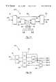
- FIG. 2is simplified block diagram of a 1 ⁇ N wavelength switch used in this invention. It has functional characteristics that are equivalent to a combination of an optical filter 10 and space-division switch 25 in FIGS. 1 b and 1 c.
- FIG. 3 ais a simplified block diagram of a 1 ⁇ 4 wavelength switch.
- FIG. 3 bis a table of the eight eigen states corresponding to the three control bits of the 1 ⁇ 4 wavelength switch 100 , 200 shown in FIG. 3 a.
- FIGS. 4 a and 4 bare simplified schematic diagrams illustrating a double-stage 1 ⁇ 2 wavelength router switch 11 , 12 , 13 in accordance with the present invention.
- FIGS. 5 a and 5 bare simplified schematic diagrams illustrating a single-stage 1 ⁇ 2 wavelength router switch 11 , 12 , 13 in accordance with the present invention.
- FIG. 6is a 1 ⁇ 4 wavelength switch based on a tree-structure.
- FIGS. 7 a and 7 bare graphs showing experimental results using three lithium niobate waveplates in the filter design.
- FIG. 7 aspectra of the output port 1 are recorded before and after switching.
- FIG. 7 bshows the corresponding spectra of the output port 2 before and after switching. The spectra are roughly equally separated.
- FIG. 8is a graph showing a design of asymmetric spectra in which the narrower spectrum one can be used as an add/drop port, and the wider spectrum can pass the remainder of the WDM signal back to the network.
- FIG. 9is a simplified block diagram of a 4 ⁇ 4 ⁇ 4 ⁇ wavelength cross-connect network implemented using two interconnected arrays of 1 ⁇ 4 wavelength switches 100 and 200 .
- FIG. 10is the table showing each of the 32 possible control states of the four 1 ⁇ 4 wavelength switches in the input array 100 and the four 1 ⁇ 4 wavelength switches in the output array 200 of the 4 ⁇ 4 ⁇ 4 ⁇ wavelength cross-connect network in FIG. 8 .
- FIG. 11is a simplified block diagram of an add/drop wavelength cross-connect switch.
- FIG. 12is a simplified block diagram of an alternative configuration in which two 2 ⁇ 2 wavelength switches 94 and 95 are added to the 1 ⁇ 4 wavelength switch 100 to perform full wavelength permutation.
- FIGS. 1 a through 1 care simplified block diagrams illustrating the three basic schemes for WDM cross-connect switches.
- FIG. 1 ais a fixed N ⁇ N ⁇ M wavelength cross-connect network.
- N optical fibers carrying M optical channelsare input to a first array 10 of 1 ⁇ M wavelength filters.
- Each wavelength filter in the first array 10separates its input WDM signal into M output channels.
- the outputs from the first array 10are interconnected in a fixed arrangement with the input ports of a second array 20 of M ⁇ 1 wavelength filters as shown in FIGS. 1 a.
- Each wavelength filter in the second array 20combines M input channels into a single output.
- FIG. 1 aFIG.
- FIG. 1 bis a block diagram of a rearrangeable WDM cross-connect network using space-division optical switches 25 to permutate the wavelength channels between the input and output arrays 10 , 20 .
- FIG. 1 cis a wavelength-interchanging cross-connect network using wavelength converters 27 .
- FIG. 2is a simplified block diagram illustrating a wavelength switch 100 that has functional characteristics equivalent to the combination of a filter 10 and a space-division switch 25 in FIGS. 1 b and 1 c.
- FIG. 3 ashow more detail of a 1 ⁇ 4 wavelength switch using 1 ⁇ 2 wavelength switches 11 , 12 , and 13 .
- Each 1 ⁇ 2 wavelength switch 11 , 12 , 13is controlled by one control bit and hence has two control states. Therefore, the 1 ⁇ 4 wavelength switch has three control bits (C 0 , C 1 , and C 2 ) that result in eight (2 3 ) different output combinations. These eight combinations are designated “a” through “h”, respectively, in FIG. 3 b.
- These 1 ⁇ 4 wavelength switchesare used to form the 4 ⁇ 4 ⁇ 4 ⁇ wavelength cross-connect network illustrated in FIG. 9 .
- a 4 ⁇ 4 ⁇ 4 ⁇ optical wavelength cross-connect networkcan be created.
- the 1 ⁇ 4 wavelength switches in the present inventionare inherently bi-directional, so that the order of the input port and the output ports can be reversed to permit light to pass in either direction through the switch.
- the allowed states for this wavelength cross-connect networkare shown in FIG. 10, where “a” through “h” represent the optical channel arrangements listed in FIG. 3 b for each 1 ⁇ 4 wavelength switch in the two arrays 100 , 200 .
- a total of 32 different combinationsare allowed without running into the wavelength collision or recombination problems.
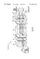
- FIG. 4 a and FIG. 4 bare schematic diagrams illustrating the two control states of a 1 ⁇ 2 wavelength switch 11 , 12 , and 13 , which is one of the fundamental building blocks used in construction of the 1 ⁇ 4 wavelength switch 100 in FIG. 2 .
- Each 1 ⁇ 2 wavelength switch 11 , 12 , 13is under binary control from a control bit and hence has two control states.
- the 1 ⁇ 2 wavelength switchserves to separate channels of the wavelength spectrum applied to the input port and determines which of the two output ports are coupled to each channel.
- each of the subsetsmay comprise more than one channel and may itself be a WDM signal although having a smaller bandwidth than the original WDM signal.
- Each of the optical pathsis further labeled with either a horizontal double-headed line indicating horizontal polarization, or a vertical double-headed line indicating vertical polarization, or both horizontal and vertical double-headed lines indicating mixed horizontal and vertical polarizations in the optical signal at that point.
- the input WDM signalenters the first polarization separation element 30 (e.g., a birefringent element or polarized beamsplitter) that spatially separates horizontal and vertically polarized components of the input WDM signal.
- the birefringent materialallows the vertically polarized portion of the optical signal to pass through without changing course because they are ordinary waves in the birefringent element 30 .
- horizontally polarized wavesare redirected at an angle because of the birefringent walk-off effect. The angle of redirection is a well-known function of the particular materials chosen.
- the horizontally polarized componenttravels along a path 101 as an extraordinary signal in the first polarization separation element 30 while the vertically polarized component 102 travels as an ordinary signal and passes through without spatial reorientation.
- the resulting signals 101 and 102both carry the full frequency spectrum of the input WDM signal.
- Both the horizontally and vertically polarized components 101 and 102are coupled to a switchable polarization rotator 40 under control of a control bit.
- the polarization rotator 40consists of two sub-element rotators that form a complementary state, i.e. when one turns on the other turns off.
- the rotator 40selectively rotates the polarization state of either signal 101 or 102 by a predefined amount. In the preferred embodiment, the rotator 40 rotates the signals by either 0° (i.e., no rotation) or 90°.
- the polarization rotator 40can be a twisted nematic liquid crystal rotator, ferroelectric liquid crystal rotator, pi-cell based liquid crystal rotator, magneto-optic based Faraday rotator, acousto-optic or electro-optic based polarization rotator.
- Commercially available rotators based on liquid crystal technologyare preferred, although other rotator technologies may be applied to meet the needs of a particular application.
- the switching speed of these elementsranges from a few milliseconds to nanoseconds, and therefore can be applied to a wide variety of systems to meet the needs of a particular application.
- FIG. 4 aillustrates the control state in which the signal 102 is rotated by 90° so that both signals 103 , 104 exiting the rotator 40 have a horizontal polarization.
- FIG. 2 billustrates the second control state in which the polarization of the signal 101 is rotated by 90° so that both optical signals 103 , 104 exiting the rotator 40 have a vertical polarization.
- both the horizontal and vertical componentscontain the entire frequency spectrum of channels in the input WDM signal.
- the stacked waveplates element 61is a stacked plurality of birefringent waveplates at selected orientations that generate two eigen states.
- the first eigen statecarries a first sub-spectrum with the same polarization as the input
- the second eigen statecarries a complementary sub-spectrum at the orthogonal polarization:
- the polarization of the incoming beam and the two output polarizationsform a pair of spectral responses, where (H, H) and (V, V) carry the first part of the input spectrum and (H, V) and (V, H) carry the complementary (second) part of the input spectrum, where V and H are vertical and horizontal polarization, respectively.
- FIGS. 4 a and 4 bThis may be better understood by comparing FIGS. 4 a and 4 b.
- horizontal polarizations 103 , 104 input to the stacked waveplates element 61 as shown in FIG. 4 aorthogonal vertical and horizontal polarizations are generated with the first spectral band residing in horizontal polarization and the second spectral band residing in vertical polarization.
- vertical polarizations 103 , 104 input to the stacked waveplates element 61 as shown in FIG. 4 borthogonal vertical and horizontal polarizations are generated with the first spectral band residing in vertical polarization and the second spectral band residing in horizontal polarization.
- the stacked waveplates element 61has a comb filter response curve with a substantially flat top or square wave spectral response.
- the stacked waveplates element 61has an asymmetric filter response.
- the pairs of optical responses 105 , 106 output by the stacked waveplates element 61are coupled to a polarization-dependent routing element 50 (e.g., a second birefringent element or a polarized beamsplitter).
- This polarization-dependent routing element 50spatially separates the horizontally and vertically polarized components of the input optical signals 105 and 106 .
- the optical signals 105 , 106are broken into vertically polarized components 107 , 108 containing the second spectral band and horizontally polarized components 109 , 110 containing the first spectral band.
- the two orthogonal polarizations that carry first spectral band 109 , 110 in horizontal polarization and second set spectral band 107 , 108 in vertical polarizationare separated by the polarization-dependent routing element 50 .
- the second stacked waveplates element 62has substantially the same composition as the first stacked waveplates element 61 .
- the horizontally polarized beams 109 , 110 input to the second stacked waveplates element 62are further purified and maintain their polarization when they exit the second stacked waveplates element 62 .
- the vertically polarized beams 107 , 108experience a 90° polarization rotation and are also purified when they exit the second stacked waveplates element 62 .
- the 90° polarization rotationis due to the fact that the vertically polarized beams 107 , 108 carry the second spectral band and therefore are in the complementary state of element 62 .
- all four beams 111 , 112 and 113 , 114have horizontal polarization.
- the spectral bands defined by the filter characteristics of the stacked waveplates elements 61 , 62are separated with the second spectral band 501 on top and the first spectral band 502 below.
- a second polarization rotator 41 and a polarization combining element 70are used.
- the second rotator 41has two sub-elements that intercept the four parallel beams 111 - 114 .
- the two sub-elements of the second rotator 41are set at a complementary state to the first rotator 40 , i.e. when the first rotator 40 is turned on/off, the second rotator 41 is turned off/on. In the case of FIG.
- polarization combining element 70e.g., a third birefringent element
- a polarization combining element 70recombines the two orthogonal polarizations 115 , 116 and 117 , 118 using the walk-off effect to produce two spectra that exit at ports 14 and 13 , respectively. This completes the first control state of the 1 ⁇ 2 wavelength router.
- FIG. 4 bshows the other control state in which the two polarization rotators 40 and 41 have switched to their complimentary states, i.e. from on to off, or off to on, in contrast to their states shown in FIG. 4 a.
- the full input spectrumis first divided by polarization into two orthogonal states, i.e. vertical and horizontal polarization as indicated at 101 and 102 , by the first polarization separation element 30 .
- the first polarization rotator 40is now set to have the output polarizations 103 and 104 both vertical.
- two orthogonal polarizationsi.e., horizontal and vertical
- carry second and first spectral bandsare generated, respectively.
- horizontal polarizationis used to carry the second spectral band
- vertical polarizationis used to carry the first spectral band of the input WDM spectrum.
- the two spectral bandsare then spatially separated by the polarization-dependent routing element 50 with vertical polarization 107 , 108 going upward and horizontal polarization 109 , 110 passing through without deviation. This, therefore, separates the two spectral bands according to their polarizations.
- the four resulting beams 107 - 110enter the second stacked waveplates element 62 for further spectral purification.
- element 62Another important role of element 62 is its polarization rotation for the second spectral band.
- the stacked waveplates elements 61 , 62have two eigen states.
- the vertically polarized beams 107 , 108remain unchanged by element 62 .
- the horizontally polarized beams 109 and 110are rotated by 90° as they pass through element 62 because they are in the complementary state of the stacked waveplate 62 .
- a second polarization rotator 41 and a polarization combining element 70are used, as previously discussed.
- the second rotator 41is set to rotate the polarizations of beams 112 and 114 by 90° and to pass beams 111 and 112 without rotation.
- the resulting beams 115 - 118are recombined by the polarization combining element 70 and exit at the output ports 1 and 2 for the first and second spectral bands, respectively.
- FIGS. 5 a and 5 bshow the two control states of a simplified, alternative embodiment of the 1 ⁇ 2 wavelength router switch.
- the embodiment depicted in FIGS. 5 a and 5 bis a single-stage switchable wavelength router that incorporates two changes.
- the second stacked waveplates element 62 in FIGS. 4 a and 4 bhas been removed and the second polarization rotator 41 has been replaced with a passive polarization rotator with two sub-elements to intercept the beams 108 and 109 , as shown in FIGS. 5 a and 5 b.
- the single-stage wavelength router switchoperates in substantially the same manner as the double-stage router until the beams 107 - 110 exit the polarization-dependent routing element 50 .
- the divided first and second spectral bandsare carried by two sets of orthogonally polarized beams 107 , 108 and 109 , 110 , respectively.
- the positions of the first and second spectral bandsdepend on the polarization state of the beams 103 and 104 . If the first spectral band is horizontally polarized by the first rotator 40 , it will exit at the lower output port 2 and the second spectral band will exit at the upper output port 1 .
- the first spectral bandis vertically polarized by the first rotator 40 , it will exit at the upper output port 1 and the second spectral band will exit at the lower output port 2 . Because of the birefringent walk-off effect in the polarization-dependent routing element 50 , the vertically polarized light beams 107 , 108 deviate from their original paths and travel upward, whereas the horizontally polarized beams 109 , 110 pass through element 50 without changing their directions. The two pairs of beams 107 , 108 and 109 , 110 exiting the polarization-dependent routing element 50 have the same polarization but different frequencies.
- the passive polarization rotator 41is patterned to rotate polarization only in the areas that intercept beams 108 and 109 . Therefore, at the output of the rotator 41 , orthogonally polarized pairs of beams 115 , 116 and 117 , 118 are produced for both the first and second spectral bands. These beams 115 - 118 are then recombined by the polarization combining element 70 and exit at output ports 2 and 1 .
- the single-stage switchable wavelength routerhas the advantages of requiring fewer components as compared to the double-stage router. However, its spectral purity is not as good as the double-stage router. It will depend on the applications and requirements of a specific WDM network, whether the single stage or the double stage wavelength router is preferred.
- One advantage of the present inventionis that routing is accomplished while conserving substantially all optical energy available in the input WDM signal. That is to say, regardless of the polarization of the signals in input WDM signal both the horizontal and vertically polarized components are used and recombined at the output ports resulting in very low loss through the router.
- FIGS. 7 a and 7 bare graphs showing examples of the transmission characteristics of a stacked waveplates element with equally separated sub-spectra having a channel spacing of about 8 nm.
- Three lithium niobate (LiNbO 3 ) waveplates having a thickness of 1 mmhave been stacked together to form a flat-top, equally divided spectrum, as shown in FIGS. 7 a and 7 b, with channel crosstalk under 30 dB.
- the experimental resultsare based on the double-stage switchable wavelength router.
- this 1 ⁇ 2 wavelength switchis inherently bi-directional, as previously discussed, so that light can pass either from the input port to the output ports or from the output ports to the input port. This enables the 1 ⁇ 2 wavelength switch to be used as a component in fabrication of bi-directional 1 ⁇ 4 wavelength switches and cross-connect networks.
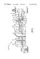
- FIG. 6is a simplified schematic diagram of an alternative embodiment of a 1 ⁇ 4 wavelength switch using a tree architecture.
- This tree architecturecan be extended to a 1 ⁇ 2 N geometry using N stages of cascading.
- the optical input to the wavelength switchis divided by a first polarization separation element 21 (e.g., a first birefringent element) into an orthogonally-polarized pair of beams.
- a first polarization separation element 21e.g., a first birefringent element
- These two beamspass through a two-pixel polarization rotator 22 that rotates the polarization of one of the beams so that the state of polarization (SOP) of the two beams is the same (i.e., either vertical or horizontal) depending on the control state of the switch.
- SOPstate of polarization
- Both beamsthen enter a first wavelength filter 23 (e.g., a stacked waveplates element, as previously discussed), in which the input spectrum is separated into two complementary eigen states.
- the first eigen statecarries a first sub-spectrum with the same polarization as the input, while the second eigen state carries a complementary sub-spectrum at the orthogonal polarization.
- the polarization of the incoming beam and the two output polarizationsform a pair of spectral responses, where (H,H) and (V,V) carry the first part of the input spectrum and (H,V) and (V,H) carry the complementary (second) portion of the input spectrum.
- V and Hindicate vertical and horizontal polarizations, respectively.
- orthogonal vertical and horizontal polarizationsare generated with the first spectral band residing in horizontal polarization and the second spectral band residing in vertical polarization.
- orthogonal vertical and horizontal polarizationsare generated with the first spectral band residing in vertical polarization and the second spectral band residing in horizontal polarization.
- the two polarization-coded spectra exiting the first wavelength filter 23are separated by the polarization beam separator 24 (e.g., a polarized beamsplitter).
- the horizontally-polarized components of these beamscarry the first part of the spectrum and pass straight through the polarization beam separator 24 .
- the vertically-polarized components of the beamscarry the second part of the spectrum and are reflected by 90 degrees.
- Both of the sub-spectrum exiting the polarization separator 24are further modulated by a second polarization rotator 25 , 32 that rotates the polarization by either 0 or 90 degrees depending on the control state of the device. Therefore, two SOPs are possible after the second polarization rotator 25 , 32 .
- the beamthen enters another wavelength filter 26 , 33 that has a narrower spectral response than the first wavelength filter 23 , and can further slice the spectrum into a smaller bandwidth.
- the third and fourth parts of the sub-spectra generated by the second wavelength filter 26 , 33are coded within two orthogonal polarizations and are spatially separated by another polarization separator 27 , 34 .
- the vertically-polarized beamsare reflected by 90 degrees by the polarization separator 27 , 34 .
- the polarization of one of the beamsis rotated by the pixelized polarization rotator 30 , 37 .
- the resulting orthogonal polarizationscarry the first (third) of the four part of the full spectrum is recombined by the polarization combiner 31 , 38 and exits to output port 1 ( 3 ).
- the horizontally-polarized beamspass straight through the polarization separator 27 , 34 and are modulated by the polarization rotator 38 , 35 .
- This portion of the light energycarries the second (fourth) part of the spectrum, and is recombined by the polarization combiner 29 , 36 and exits at output port 2 ( 4 ).
- FIG. 11is a simplified block diagram showing an optical add/drop wavelength switch 250 used in the cross-connect network configurations.
- the add/drop wavelength switch 250is made by combining a number of 1 ⁇ 2 wavelength switches (see, FIGS. 4 a, 4 b, 5 a, and 5 b ) using the combinations of control states shown in FIG. 3 b.
- asymmetric spectral slicingis preferred.
- FIG. 8is an example of asymmetric sub-spectra produced by the stacked waveplates element in the 1 ⁇ 2 wavelength switch, in which one output port carries a much narrower spectral width compared to the other port.
- the add/drop filtercan be either passive or active, depending on system design and requirements.
- the switching elementi.e., the switchable polarization rotator arrays
- the switching elementcan be replaced by two passive half-wave plates at each corresponding position of the polarization rotator, such that one of the ports is always designated as the add/drop port.
- the rest of the optical channelspass through the wavelength router and continue to propagate along the WDM network.
- the input WDM signal 80is divided into two parts by the first 1 ⁇ 2 wavelength switch 81 .
- the pass-through channels 82are passed to the final 1 ⁇ 2 wavelength switch 83 and return uninterrupted through the output port 89 to the network.
- the drop channels 84can be further divided into two sub-spectra 86 by a 1 ⁇ 2 wavelength switch 85 .
- two add channels 87are combined by a 1 ⁇ 2 wavelength switch 88 , which are then combined with the pass-through channels 82 by the final 1 ⁇ 2 switch 83 .
- the wavelength switches used in FIG. 11can be either active or passive or a combination of both.
- switches 81 and 83are passive and serve as the primary add/drop spectral separators.
- the following wavelength switches 85 and 88actively switch the sub-spectra between the output/input ports 86 and 87 .
- the add/drop wavelength switchcan drop the eighth and ninth channels that exit to port 84 . These two channels can be further exchanged at the output port of switch 86 under the control of single control bit.
- each 1 ⁇ 4 wavelength switchhas one port that receives a WDM optical signal, which is separated into four optical channels at the four output ports.
- the three control bits C 0 , C 1 , and C 2allow eight (2 3 ) control states for the 1 ⁇ 4 wavelength switch.
Landscapes
- Physics & Mathematics (AREA)
- General Physics & Mathematics (AREA)
- Optics & Photonics (AREA)
- Engineering & Computer Science (AREA)
- Computer Networks & Wireless Communication (AREA)
- Nonlinear Science (AREA)
- Optical Modulation, Optical Deflection, Nonlinear Optics, Optical Demodulation, Optical Logic Elements (AREA)
- Use Of Switch Circuits For Exchanges And Methods Of Control Of Multiplex Exchanges (AREA)
- Optical Communication System (AREA)
Abstract
Description
Claims (58)
Priority Applications (1)
| Application Number | Priority Date | Filing Date | Title |
|---|---|---|---|
| US09/447,091US6175432B1 (en) | 1996-07-23 | 1999-11-22 | Multi-wavelength cross-connect optical network |
Applications Claiming Priority (5)
| Application Number | Priority Date | Filing Date | Title |
|---|---|---|---|
| US08/685,150US5724165A (en) | 1996-07-23 | 1996-07-23 | Fault-tolerant optical routing switch |
| US08/739,424US5867291A (en) | 1996-10-29 | 1996-10-29 | Programmable wavelength router |
| US08/780,291US5694233A (en) | 1996-07-23 | 1997-01-08 | Switchable wavelength router |
| US08/907,551US6005697A (en) | 1996-07-23 | 1997-08-08 | Multi-wavelength cross-connect optical network |
| US09/447,091US6175432B1 (en) | 1996-07-23 | 1999-11-22 | Multi-wavelength cross-connect optical network |
Related Parent Applications (1)
| Application Number | Title | Priority Date | Filing Date |
|---|---|---|---|
| US08/907,551ContinuationUS6005697A (en) | 1996-07-23 | 1997-08-08 | Multi-wavelength cross-connect optical network |
Publications (1)
| Publication Number | Publication Date |
|---|---|
| US6175432B1true US6175432B1 (en) | 2001-01-16 |
Family
ID=27418453
Family Applications (2)
| Application Number | Title | Priority Date | Filing Date |
|---|---|---|---|
| US08/907,551Expired - Fee RelatedUS6005697A (en) | 1996-07-23 | 1997-08-08 | Multi-wavelength cross-connect optical network |
| US09/447,091Expired - Fee RelatedUS6175432B1 (en) | 1996-07-23 | 1999-11-22 | Multi-wavelength cross-connect optical network |
Family Applications Before (1)
| Application Number | Title | Priority Date | Filing Date |
|---|---|---|---|
| US08/907,551Expired - Fee RelatedUS6005697A (en) | 1996-07-23 | 1997-08-08 | Multi-wavelength cross-connect optical network |
Country Status (1)
| Country | Link |
|---|---|
| US (2) | US6005697A (en) |
Cited By (36)
| Publication number | Priority date | Publication date | Assignee | Title |
|---|---|---|---|---|
| US6301046B1 (en)* | 1999-12-31 | 2001-10-09 | Jds Uniphase Corporation | Interleaver/deinterleavers causing little or no dispersion of optical signals |
| US6337934B1 (en) | 1998-08-27 | 2002-01-08 | Chorum Technologies, Inc. | NxN switch array with polarization displacer |
| US20020044318A1 (en)* | 2000-10-16 | 2002-04-18 | Henry Hung | Add/drop apparatus using multiple wavelength michelson interferometer |
| US6396609B1 (en) | 1999-12-20 | 2002-05-28 | Chorum Technologies, Lp | Dispersion compensation for optical systems |
| US6404536B1 (en)* | 2000-12-30 | 2002-06-11 | Industrial Technology Research Institute | Polarization independent tunable acousto-optical filter and the method of the same |
| US20020131117A1 (en)* | 2001-03-19 | 2002-09-19 | At&T Corporation | Delivering multicast services on a wavelength division multiplexed network using a configurable four-port wavelength selective crossbar switch |
| US6476967B2 (en)* | 2001-03-27 | 2002-11-05 | Industrial Technology Research Institute | Compact optical circulator with three ports |
| US6493139B1 (en)* | 2001-03-16 | 2002-12-10 | Hongdu Liu | Optical switch |
| US6493117B1 (en) | 1997-08-27 | 2002-12-10 | Nortel Networks Limited | WDM optical network with passive pass-through at each node |
| US6519060B1 (en)* | 1999-06-04 | 2003-02-11 | Chorum Technologies Lp | Synchronous optical network in frequency domain |
| US6532090B1 (en)* | 2000-02-28 | 2003-03-11 | Lucent Technologies Inc. | Wavelength selective cross-connect with reduced complexity |
| US6549548B2 (en) | 2000-10-25 | 2003-04-15 | Axsun Technologies, Inc. | Interferometric filter wavelength meter and controller |
| US6552833B2 (en) | 1997-04-15 | 2003-04-22 | Macro-Vision Communications, Inc. | Programmable optical add/drop multiplexer |
| US6559992B2 (en) | 2000-03-27 | 2003-05-06 | Chorum Technologies Lp | Adjustable chromatic dispersion compensation |
| US6600582B1 (en) | 1997-03-24 | 2003-07-29 | Chorum Technologies Lp | Optical add/drop wavelength switch |
| US20030156317A1 (en)* | 2000-03-10 | 2003-08-21 | Ruhl Frank Friedrich | Communications network architecture |
| US6697550B2 (en) | 2001-10-24 | 2004-02-24 | Renka Corporation | Fast 1×N fiber-optic switch |
| US6731833B2 (en) | 2001-01-16 | 2004-05-04 | T-Rex Enterprises Corp. | Optical cross connect switch |
| US6751372B2 (en) | 2001-03-19 | 2004-06-15 | At&T Corp | Four-port wavelength-selective crossbar switches (4WCS) using reciprocal WDM MUX-DEMUX and optical circulator combination |
| US20040165015A1 (en)* | 2003-02-20 | 2004-08-26 | Blum Ronald D. | Electronic display device for floor advertising/messaging |
| US6801310B2 (en) | 2001-11-07 | 2004-10-05 | Arroyo Optics, Inc. | Liquid crystal modulator and polarization diversity optics for optical communications |
| US20040212897A1 (en)* | 2000-02-25 | 2004-10-28 | Tedesco James M. | Configurable wavelength routing device |
| US20040247312A1 (en)* | 2001-12-03 | 2004-12-09 | Fujitsu Limited | Optical communication system |
| US6839517B2 (en) | 2001-02-12 | 2005-01-04 | Agere Systems Inc. | Apparatus and method for transmitting optical signals through a single fiber optical network |
| US7010225B1 (en)* | 2000-12-29 | 2006-03-07 | Nortel Networks Limited | Technique for interchanging wavelengths in a multi-wavelength system |
| US20060152483A1 (en)* | 1999-05-04 | 2006-07-13 | Blum Ronald D | Floor covering with voice-responsive display |
| US7202996B2 (en)* | 2001-08-16 | 2007-04-10 | Telefonaktiebolaget Lm Ericsson (Publ) | Optical amplifier |
| US20070222633A1 (en)* | 1999-05-04 | 2007-09-27 | Intellimats, Llc | Advanced floor mat |
| US20080145053A1 (en)* | 2001-09-03 | 2008-06-19 | Melanie Holmes | Optical processing |
| US20080230497A1 (en)* | 1999-05-04 | 2008-09-25 | Intellimat, Inc. | Edge display |
| US20090052837A1 (en)* | 2007-08-08 | 2009-02-26 | Teliware Ltd. | Polarization-based optical switching |
| US7511630B2 (en) | 1999-05-04 | 2009-03-31 | Intellimat, Inc. | Dynamic electronic display system with brightness control |
| US20090196549A1 (en)* | 2001-03-16 | 2009-08-06 | Meriton Networks Us Inc. | Modular all-optical cross-connect |
| US20100119226A1 (en)* | 2008-11-07 | 2010-05-13 | Mahmoud Rasras | Reconfigurable dwdm wavelength switch based on complementary bandpass filters |
| US10257594B2 (en) | 2012-08-15 | 2019-04-09 | Thomas Swan And Co., Ltd. | Optical device and methods |
| US10439302B2 (en) | 2017-06-08 | 2019-10-08 | Pct International, Inc. | Connecting device for connecting and grounding coaxial cable connectors |
Families Citing this family (51)
| Publication number | Priority date | Publication date | Assignee | Title |
|---|---|---|---|---|
| US6005697A (en)* | 1996-07-23 | 1999-12-21 | Macro-Vision Communications, L.L.C. | Multi-wavelength cross-connect optical network |
| US6545783B1 (en)* | 1996-10-29 | 2003-04-08 | Chorum Technologies Lp | Optical wavelength add/drop multiplexer |
| US6847786B2 (en)* | 1996-10-29 | 2005-01-25 | Ec-Optics Technology, Inc. | Compact wavelength filter using optical birefringence and reflective elements |
| US6208442B1 (en) | 1998-03-26 | 2001-03-27 | Chorum Technologies, Inc. | Programmable optical multiplexer |
| US6243200B1 (en)* | 2000-03-02 | 2001-06-05 | Chorum Technologies, Inc. | Optical wavelength router based on polarization interferometer |
| US6519022B1 (en)* | 1997-04-02 | 2003-02-11 | Chorum Technologies Lp | Optical routing switch using symmetric liquid crystal cells |
| US6049404A (en)* | 1997-04-02 | 2000-04-11 | Macro-Vision Communications Inc. | N+M digitally programmable optical routing switch |
| US6094246A (en) | 1998-01-06 | 2000-07-25 | Chorum Technologies | Acute twist nematic liquid crystal electro-optic modulator for use in an infrared optical communication system having extinction ratio of -25db |
| US6236480B1 (en)* | 1998-05-01 | 2001-05-22 | Dogan A. Atlas | System and method for reducing Raman cross-talk in a DWDM transport system |
| US6493119B1 (en) | 1999-09-07 | 2002-12-10 | Chien-Yu Kuo | Scalable DWDM network switch architecture with wavelength tunable sources |
| US6373604B1 (en)* | 1999-10-01 | 2002-04-16 | New Focus, Inc. | Optical MUX/DEMUX |
| US6337770B1 (en)* | 1999-12-31 | 2002-01-08 | Jds Uniphase Corporation | Single-pass folded interleaver/deinterleavers |
| US6215923B1 (en)* | 2000-01-31 | 2001-04-10 | Oplink Communications, Inc. | Optical interleaver |
| US6687462B1 (en)* | 2000-02-01 | 2004-02-03 | Oplink Communications, Inc. | Wavelength slicer for optical signal switching |
| US6862380B2 (en)* | 2000-02-04 | 2005-03-01 | At&T Corp. | Transparent optical switch |
| US6498872B2 (en)* | 2000-02-17 | 2002-12-24 | Jds Uniphase Inc. | Optical configuration for a dynamic gain equalizer and a configurable add/drop multiplexer |
| US7031607B1 (en) | 2000-02-21 | 2006-04-18 | Nortel Networks Limited | MPLS application to optical cross-connect using wavelength as a label |
| CA2337296A1 (en)* | 2000-03-03 | 2001-09-03 | E-Tek Dynamics, Inc. | Interleaver/deinterleavers causing little or no dispersion of optical signals |
| US6252711B1 (en)* | 2000-03-21 | 2001-06-26 | Lucent Technologies, Inc | Polarization diversity for birefingent filters |
| CN1133084C (en) | 2000-03-24 | 2003-12-31 | 信息产业部武汉邮电科学研究院 | Comb method for dividing waves |
| US6490377B1 (en)* | 2000-05-01 | 2002-12-03 | Oplink Communications, Inc. | Optical interleaver |
| US7486443B1 (en)* | 2000-06-05 | 2009-02-03 | Avanex Corporation | High extinction ratio and low crosstalk compact optical switches |
| US6687054B2 (en) | 2000-06-07 | 2004-02-03 | Cirvine Corporation | Apparatus and method for low dispersion in communications |
| US6693743B2 (en) | 2000-06-07 | 2004-02-17 | Cirvine Corporation | Birefringent devices |
| US6731430B2 (en) | 2000-06-07 | 2004-05-04 | Cirvine Corporation | Low crosstalk flat band filter |
| US6781754B2 (en) | 2000-06-07 | 2004-08-24 | Cirvine Corporation | Interleaver using spatial birefringent elements |
| US6628449B2 (en) | 2000-11-01 | 2003-09-30 | Cirvine Corporation | Tandem comb filter |
| US6563641B2 (en) | 2000-06-23 | 2003-05-13 | Cirvine Corporation | Fold interleaver |
| CN1451211A (en)* | 2000-08-15 | 2003-10-22 | 北方电信网络有限公司 | Optical switch router |
| JP3744343B2 (en)* | 2000-11-08 | 2006-02-08 | 日本電気株式会社 | Optical cross-connect device |
| US6807371B1 (en)* | 2000-11-27 | 2004-10-19 | Nortel Networks Limited | Reconfigurable add-drop multiplexer |
| US6792175B2 (en)* | 2000-11-30 | 2004-09-14 | Board Of Supervisors Of Louisiana State University And Agricultural And Mechanical College | Optical crossbar switch |
| US6429962B1 (en)* | 2000-12-05 | 2002-08-06 | Chorum Technologies Lp | Dynamic gain equalizer for optical amplifiers |
| US6614573B1 (en) | 2001-01-30 | 2003-09-02 | Avanex Corporation | Switchable interleaved channel separator devices and systems |
| US6694066B2 (en) | 2001-02-14 | 2004-02-17 | Finisar Corporation | Method and apparatus for an optical filter |
| US6684002B2 (en) | 2001-02-14 | 2004-01-27 | Finisar Corporation | Method and apparatus for an optical filter |
| US6407846B1 (en) | 2001-03-16 | 2002-06-18 | All Optical Networks, Inc. | Photonic wavelength shifting method |
| US6934508B2 (en)* | 2001-03-19 | 2005-08-23 | Navigaug Inc. | System and method for obtaining comprehensive vehicle radio listener statistics |
| US6611648B2 (en)* | 2001-05-09 | 2003-08-26 | Corning Incorporated | Optical fibers having cores with different propagation constants, and methods of manufacturing same |
| US6809863B2 (en) | 2001-06-07 | 2004-10-26 | Cirvine Corporation | Low dispersion filters |
| US7106508B2 (en)* | 2001-06-11 | 2006-09-12 | Finisar Corporation | Hybrid cell |
| US6639707B2 (en) | 2001-06-25 | 2003-10-28 | Cirvine Corporation | Tandem interleaver |
| US6900938B2 (en) | 2001-06-25 | 2005-05-31 | Bin Zhao | Low dispersion interleaver |
| US7173763B2 (en)* | 2002-06-12 | 2007-02-06 | Finisar Corporation | Optical interleaver and filter cell design with enhanced clear aperture |
| US7268944B2 (en)* | 2002-06-12 | 2007-09-11 | Finisar Corporation | Optical interleaver, filter cell, and component design with reduced chromatic dispersion |
| US6850364B2 (en) | 2002-06-12 | 2005-02-01 | Finisar Corporation | Method and apparatus for an optical multiplexer and demultiplexer with an optical processing loop |
| US20040223222A1 (en)* | 2002-06-12 | 2004-11-11 | Schott Daniel Philip | Hermetically sealed collimator and optical interleaver design |
| US20040227996A1 (en)* | 2002-06-12 | 2004-11-18 | Tengda Du | Optical interleaver and filter cell design with enhanced thermal stability |
| US7292786B1 (en)* | 2002-09-24 | 2007-11-06 | Avanex Corporation | Method and system for a re-configurable optical multiplexer, de-multiplexer and optical add-drop multiplexer |
| CN103379069B (en)* | 2012-04-13 | 2016-10-05 | 菲尼萨公司 | Without hot DQPSK and/or DPSK demodulator |
| US9780872B2 (en)* | 2014-07-23 | 2017-10-03 | University Of Southern California | Adaptive optics based simultaneous turbulence compensation of multiple orbital angular momentum beams |
Citations (18)
| Publication number | Priority date | Publication date | Assignee | Title |
|---|---|---|---|---|
| US4834483A (en) | 1987-05-06 | 1989-05-30 | Bell Communications Research, Inc. | Fast optical cross-connect for parallel processing computers |
| US4919522A (en) | 1988-02-25 | 1990-04-24 | Geo-Centers, Inc. | Optical switch having birefringent element |
| US5136671A (en) | 1991-08-21 | 1992-08-04 | At&T Bell Laboratories | Optical switch, multiplexer, and demultiplexer |
| US5181134A (en) | 1991-03-15 | 1993-01-19 | At&T Bell Laboratories | Photonic cross-connect switch |
| US5363228A (en) | 1993-03-05 | 1994-11-08 | General Electric Company | Optical device with spatial light modulators for switching arbitrarily polarized light |
| US5381250A (en) | 1992-11-06 | 1995-01-10 | Displaytech, Inc. | Electro-optical switch with 4 port modules with electro-optic polarization rotators |
| US5414540A (en)* | 1993-06-01 | 1995-05-09 | Bell Communications Research, Inc. | Frequency-selective optical switch employing a frequency dispersive element, polarization dispersive element and polarization modulating elements |
| US5414541A (en) | 1993-06-01 | 1995-05-09 | Bell Communications Research, Inc. | Optical switch employing first and second ferroelectric cells with alignment layers having alignment directions offset by 45° |
| US5457556A (en) | 1993-04-16 | 1995-10-10 | Nec Corporation | Optical cross-connect system with space and wavelength division switching stages for minimizing fault recovery procedures |
| US5488500A (en) | 1994-08-31 | 1996-01-30 | At&T Corp. | Tunable add drop optical filtering method and apparatus |
| US5596661A (en) | 1994-12-28 | 1997-01-21 | Lucent Technologies Inc. | Monolithic optical waveguide filters based on Fourier expansion |
| US5606439A (en) | 1996-04-10 | 1997-02-25 | Macro-Vision Technology , Inc. | Tunable add/drop optical filter |
| US5627925A (en) | 1995-04-07 | 1997-05-06 | Lucent Technologies Inc. | Non-blocking optical cross-connect structure for telecommunications network |
| US5680490A (en) | 1995-09-08 | 1997-10-21 | Lucent Technologies Inc. | Comb splitting system and method for a multichannel optical fiber communication network |
| US5694233A (en)* | 1996-07-23 | 1997-12-02 | Macro-Vision Communications, Llc | Switchable wavelength router |
| US5809190A (en) | 1996-11-13 | 1998-09-15 | Applied Fiber Optics, Inc. | Apparatus and method of making a fused dense wavelength-division multiplexer |
| US5912748A (en)* | 1996-07-23 | 1999-06-15 | Chorum Technologies Inc. | Switchable wavelength router |
| US6005697A (en)* | 1996-07-23 | 1999-12-21 | Macro-Vision Communications, L.L.C. | Multi-wavelength cross-connect optical network |
Family Cites Families (5)
| Publication number | Priority date | Publication date | Assignee | Title |
|---|---|---|---|---|
| JPS55121215U (en)* | 1979-02-21 | 1980-08-28 | ||
| WO1989002614A1 (en)* | 1987-09-11 | 1989-03-23 | British Telecommunications Public Limited Company | An optical space switch |
| DE69013130T2 (en)* | 1989-12-28 | 1995-03-09 | Fujitsu Ltd | Optical spatial switch and network with such optical spatial switches. |
| US5867291A (en)* | 1996-10-29 | 1999-02-02 | Chorum Technologies Inc. | Programmable wavelength router |
| US5724165A (en)* | 1996-07-23 | 1998-03-03 | Macro-Vision Communications, L.L.C. | Fault-tolerant optical routing switch |
- 1997
- 1997-08-08USUS08/907,551patent/US6005697A/ennot_activeExpired - Fee Related
- 1999
- 1999-11-22USUS09/447,091patent/US6175432B1/ennot_activeExpired - Fee Related
Patent Citations (18)
| Publication number | Priority date | Publication date | Assignee | Title |
|---|---|---|---|---|
| US4834483A (en) | 1987-05-06 | 1989-05-30 | Bell Communications Research, Inc. | Fast optical cross-connect for parallel processing computers |
| US4919522A (en) | 1988-02-25 | 1990-04-24 | Geo-Centers, Inc. | Optical switch having birefringent element |
| US5181134A (en) | 1991-03-15 | 1993-01-19 | At&T Bell Laboratories | Photonic cross-connect switch |
| US5136671A (en) | 1991-08-21 | 1992-08-04 | At&T Bell Laboratories | Optical switch, multiplexer, and demultiplexer |
| US5381250A (en) | 1992-11-06 | 1995-01-10 | Displaytech, Inc. | Electro-optical switch with 4 port modules with electro-optic polarization rotators |
| US5363228A (en) | 1993-03-05 | 1994-11-08 | General Electric Company | Optical device with spatial light modulators for switching arbitrarily polarized light |
| US5457556A (en) | 1993-04-16 | 1995-10-10 | Nec Corporation | Optical cross-connect system with space and wavelength division switching stages for minimizing fault recovery procedures |
| US5414541A (en) | 1993-06-01 | 1995-05-09 | Bell Communications Research, Inc. | Optical switch employing first and second ferroelectric cells with alignment layers having alignment directions offset by 45° |
| US5414540A (en)* | 1993-06-01 | 1995-05-09 | Bell Communications Research, Inc. | Frequency-selective optical switch employing a frequency dispersive element, polarization dispersive element and polarization modulating elements |
| US5488500A (en) | 1994-08-31 | 1996-01-30 | At&T Corp. | Tunable add drop optical filtering method and apparatus |
| US5596661A (en) | 1994-12-28 | 1997-01-21 | Lucent Technologies Inc. | Monolithic optical waveguide filters based on Fourier expansion |
| US5627925A (en) | 1995-04-07 | 1997-05-06 | Lucent Technologies Inc. | Non-blocking optical cross-connect structure for telecommunications network |
| US5680490A (en) | 1995-09-08 | 1997-10-21 | Lucent Technologies Inc. | Comb splitting system and method for a multichannel optical fiber communication network |
| US5606439A (en) | 1996-04-10 | 1997-02-25 | Macro-Vision Technology , Inc. | Tunable add/drop optical filter |
| US5694233A (en)* | 1996-07-23 | 1997-12-02 | Macro-Vision Communications, Llc | Switchable wavelength router |
| US5912748A (en)* | 1996-07-23 | 1999-06-15 | Chorum Technologies Inc. | Switchable wavelength router |
| US6005697A (en)* | 1996-07-23 | 1999-12-21 | Macro-Vision Communications, L.L.C. | Multi-wavelength cross-connect optical network |
| US5809190A (en) | 1996-11-13 | 1998-09-15 | Applied Fiber Optics, Inc. | Apparatus and method of making a fused dense wavelength-division multiplexer |
Non-Patent Citations (13)
| Title |
|---|
| Ammann, "Synthesis of Electro-Optic Shutters havin g a Prescribed Transmission vs Voltage Characteristic", Journal of the Optical Society of America (vol. 56, No. 8, pp. 1081-1088, Aug. 1966). |
| Charles A. Brackett; "Is There an Emerging Consensus on WDM Networking?"; Jun., 1996; pp. 936-941; Journal of Lightwave Technology, vol. 14, No. 6, Jun. 1996. |
| Chung et al., "Analysis of a Tunable Multichannel Two-Mode-Interference Wavelength Division Multiplexer/Demultiplexer", Journal of Lightwave Technology (vol. 7, No. 5, May 1989). |
| Damask et al., "Wavelength-Division Multiplexing using Channel-Dropping Filters", Journal of Lightwave Technology (vol. 11, No. 3, Mar. 1993). |
| Dingel and Izutsu, "Multifunction Optical Filter with a Michelson-Gires-Tournois Interferometer for Wavelength-Division-Multiplexed Network System Applications", Optical Letters (vol. 23, p. 1099, Jul. 1998). |
| Harris et al., "Optical Network Synthesis Using Birefringent Crystals. *I. Synthesis of Lossless Networks of Equal-Length Crystals", Journal of the Optical Society of America (vol. 54, No. 10, pp. 1267-1279, Oct. 1964). |
| Hideaki Okayama, Takeshi Kamijoh and Masato Kawahara; "Multiwavelength Highway Photonic Switches Using Wavelength Sorting Elements-Design", Apr. 1997; pp. 607-615; Journal of Lightwave Technology, vol. 15, No. 4, Apr. 1997. |
| Hideaki Okayama, Takeshi Kamijoh and Masato Kawahara; "Multiwavelength Highway Photonic Switches Using Wavelength Sorting Elements—Design", Apr. 1997; pp. 607-615; Journal of Lightwave Technology, vol. 15, No. 4, Apr. 1997. |
| Inoue et al., "A Four-Channel Optical Waveguide Multi/Demultiplexer foe 5-GHz Spaced Optical FDM Transmission", Journal of Lightwave Technology (vol. 6, No. 2, Feb. 1988). |
| M. Berger et al.; "Pan-European Optical Networking using Wavelength Division Multiplexing", Apr. 1997; pp. 82-88; IEEE Communications Magazine, Apr. 1997. |
| Nosu et al., "Optical FDM Transmission Technique", Journal of Lightwave Technology (vol. LT-5, No. 9, Sep. 1987). |
| Richard E. Wagner et al.; "MONET: Multiwavelength Optical Networking", Jun. 1996; pp. 1349-1355; Journal of Lightwave Technology, vol. 14, No. 6, Jun. 1996. |
| Senior et al., "Devices for Wavelength-Miltiplexing and Demultiplexing", IEE Proceedings (vol. 136, Pt. J, No. 3, Jun. 1989). |
Cited By (68)
| Publication number | Priority date | Publication date | Assignee | Title |
|---|---|---|---|---|
| US6600582B1 (en) | 1997-03-24 | 2003-07-29 | Chorum Technologies Lp | Optical add/drop wavelength switch |
| US6552833B2 (en) | 1997-04-15 | 2003-04-22 | Macro-Vision Communications, Inc. | Programmable optical add/drop multiplexer |
| US6748174B2 (en) | 1997-08-27 | 2004-06-08 | Nortel Networks Limited | WDM optical network with passive pass-through at each node |
| US6795652B2 (en) | 1997-08-27 | 2004-09-21 | Nortel Networks Limited | WDM optical network with passive pass-through at each node |
| US6775479B2 (en) | 1997-08-27 | 2004-08-10 | Nortel Networks Corporation | WDM optical network with passive pass-through at each node |
| US6631018B1 (en) | 1997-08-27 | 2003-10-07 | Nortel Networks Limited | WDM optical network with passive pass-through at each node |
| US6563615B2 (en) | 1997-08-27 | 2003-05-13 | Nortel Networks Limited | Technique for detecting noise on a data channel |
| US20030215238A1 (en)* | 1997-08-27 | 2003-11-20 | Nortel Networks Limited | WDM optical network with passive pass-through at each node |
| US6493117B1 (en) | 1997-08-27 | 2002-12-10 | Nortel Networks Limited | WDM optical network with passive pass-through at each node |
| US6892032B2 (en) | 1997-08-27 | 2005-05-10 | Nortel Networks Limited | WDM optical network with passive pass-through at each node |
| US6529300B1 (en) | 1997-08-27 | 2003-03-04 | Nortel Networks Limited | WDM optical network with passive pass-through at each node |
| US6757498B2 (en) | 1997-08-27 | 2004-06-29 | Nortel Networks Limited | WDM optical network with passive pass-through at each node |
| US6751418B2 (en) | 1997-08-27 | 2004-06-15 | Nortel Networks Limited | WDM optical network with passive pass-through at each node |
| US6556321B1 (en) | 1997-08-27 | 2003-04-29 | Nortel Networks Limited | WDM optical network and switching node with pilot tone communications |
| US6337934B1 (en) | 1998-08-27 | 2002-01-08 | Chorum Technologies, Inc. | NxN switch array with polarization displacer |
| US7629896B2 (en) | 1999-05-04 | 2009-12-08 | Intellimat, Inc. | Floor display system with interactive features and variable image rotation |
| US20070222633A1 (en)* | 1999-05-04 | 2007-09-27 | Intellimats, Llc | Advanced floor mat |
| US7456755B2 (en) | 1999-05-04 | 2008-11-25 | Intellimat, Inc. | Floor mat and system having electronic display device connectable to a network |
| US7511630B2 (en) | 1999-05-04 | 2009-03-31 | Intellimat, Inc. | Dynamic electronic display system with brightness control |
| US20080230497A1 (en)* | 1999-05-04 | 2008-09-25 | Intellimat, Inc. | Edge display |
| US20060152483A1 (en)* | 1999-05-04 | 2006-07-13 | Blum Ronald D | Floor covering with voice-responsive display |
| US6519060B1 (en)* | 1999-06-04 | 2003-02-11 | Chorum Technologies Lp | Synchronous optical network in frequency domain |
| US6396609B1 (en) | 1999-12-20 | 2002-05-28 | Chorum Technologies, Lp | Dispersion compensation for optical systems |
| US6301046B1 (en)* | 1999-12-31 | 2001-10-09 | Jds Uniphase Corporation | Interleaver/deinterleavers causing little or no dispersion of optical signals |
| US6845195B2 (en) | 2000-02-25 | 2005-01-18 | Kaiser Optical Systems | Configurable wavelength routing device |
| US20040212897A1 (en)* | 2000-02-25 | 2004-10-28 | Tedesco James M. | Configurable wavelength routing device |
| US6532090B1 (en)* | 2000-02-28 | 2003-03-11 | Lucent Technologies Inc. | Wavelength selective cross-connect with reduced complexity |
| US20030156317A1 (en)* | 2000-03-10 | 2003-08-21 | Ruhl Frank Friedrich | Communications network architecture |
| US6559992B2 (en) | 2000-03-27 | 2003-05-06 | Chorum Technologies Lp | Adjustable chromatic dispersion compensation |
| US20020044318A1 (en)* | 2000-10-16 | 2002-04-18 | Henry Hung | Add/drop apparatus using multiple wavelength michelson interferometer |
| US7095776B2 (en) | 2000-10-25 | 2006-08-22 | Axsun Technologies, Inc. | Interferometric filter wavelength meter and controller |
| US20040022283A1 (en)* | 2000-10-25 | 2004-02-05 | Axsun Technologies, Inc. | Interferometric filter wavelength meter and controller |
| US6549548B2 (en) | 2000-10-25 | 2003-04-15 | Axsun Technologies, Inc. | Interferometric filter wavelength meter and controller |
| US7010225B1 (en)* | 2000-12-29 | 2006-03-07 | Nortel Networks Limited | Technique for interchanging wavelengths in a multi-wavelength system |
| US6404536B1 (en)* | 2000-12-30 | 2002-06-11 | Industrial Technology Research Institute | Polarization independent tunable acousto-optical filter and the method of the same |
| US6731833B2 (en) | 2001-01-16 | 2004-05-04 | T-Rex Enterprises Corp. | Optical cross connect switch |
| US6839517B2 (en) | 2001-02-12 | 2005-01-04 | Agere Systems Inc. | Apparatus and method for transmitting optical signals through a single fiber optical network |
| US6493139B1 (en)* | 2001-03-16 | 2002-12-10 | Hongdu Liu | Optical switch |
| US7738748B2 (en) | 2001-03-16 | 2010-06-15 | Meriton Networks Us Inc. | Modular all-optical cross-connect |
| EP1371162A4 (en)* | 2001-03-16 | 2010-01-06 | Meriton Networks Us Inc | Modular all-optical cross-connect |
| US20090196549A1 (en)* | 2001-03-16 | 2009-08-06 | Meriton Networks Us Inc. | Modular all-optical cross-connect |
| US20020131117A1 (en)* | 2001-03-19 | 2002-09-19 | At&T Corporation | Delivering multicast services on a wavelength division multiplexed network using a configurable four-port wavelength selective crossbar switch |
| US6751372B2 (en) | 2001-03-19 | 2004-06-15 | At&T Corp | Four-port wavelength-selective crossbar switches (4WCS) using reciprocal WDM MUX-DEMUX and optical circulator combination |
| US7027733B2 (en) | 2001-03-19 | 2006-04-11 | At&T Corp. | Delivering multicast services on a wavelength division multiplexed network using a configurable four-port wavelength selective crossbar switch |
| US6476967B2 (en)* | 2001-03-27 | 2002-11-05 | Industrial Technology Research Institute | Compact optical circulator with three ports |
| US7202996B2 (en)* | 2001-08-16 | 2007-04-10 | Telefonaktiebolaget Lm Ericsson (Publ) | Optical amplifier |
| US8937759B2 (en) | 2001-09-03 | 2015-01-20 | Thomas Swan & Co. Ltd. | Optical processing |
| US10180616B2 (en) | 2001-09-03 | 2019-01-15 | Thomas Swan & Co. Ltd. | Optical processing |
| US11073739B2 (en) | 2001-09-03 | 2021-07-27 | Thomas Swan & Co. Ltd. | Optical processing |
| US10642126B2 (en) | 2001-09-03 | 2020-05-05 | Thomas Swan & Co. Ltd. | Optical processing |
| US9529325B2 (en) | 2001-09-03 | 2016-12-27 | Thomas Swan & Co. Ltd | Optical processing |
| US8335033B2 (en) | 2001-09-03 | 2012-12-18 | Thomas Swan & Co. Ltd. | Optical processing |
| US8089683B2 (en)* | 2001-09-03 | 2012-01-03 | Thomas Swan & Co. Ltd. | Optical processing |
| US20100209109A1 (en)* | 2001-09-03 | 2010-08-19 | Thomas Swan & Co. Ltd. | Optical processing |
| US20080145053A1 (en)* | 2001-09-03 | 2008-06-19 | Melanie Holmes | Optical processing |
| US6697550B2 (en) | 2001-10-24 | 2004-02-24 | Renka Corporation | Fast 1×N fiber-optic switch |
| US6801310B2 (en) | 2001-11-07 | 2004-10-05 | Arroyo Optics, Inc. | Liquid crystal modulator and polarization diversity optics for optical communications |
| US20040247312A1 (en)* | 2001-12-03 | 2004-12-09 | Fujitsu Limited | Optical communication system |
| US20060092150A1 (en)* | 2003-02-20 | 2006-05-04 | Blum Ronald D | Electronic display device with adjustable incline for floor advertising/messaging |
| US20060087501A1 (en)* | 2003-02-20 | 2006-04-27 | Blum Ronald D | Electronic display device with separately articulated portions for floor advertising/messaging |
| US20040165015A1 (en)* | 2003-02-20 | 2004-08-26 | Blum Ronald D. | Electronic display device for floor advertising/messaging |
| US8094979B2 (en) | 2007-08-08 | 2012-01-10 | Teliswitch Solutions Ltd. | Polarization-based optical switching |
| US20090052837A1 (en)* | 2007-08-08 | 2009-02-26 | Teliware Ltd. | Polarization-based optical switching |
| US20100119226A1 (en)* | 2008-11-07 | 2010-05-13 | Mahmoud Rasras | Reconfigurable dwdm wavelength switch based on complementary bandpass filters |
| US8032023B2 (en)* | 2008-11-07 | 2011-10-04 | Alcatel Lucent | Reconfigurable DWDM wavelength switch based on complementary bandpass filters |
| US10257594B2 (en) | 2012-08-15 | 2019-04-09 | Thomas Swan And Co., Ltd. | Optical device and methods |
| US10439302B2 (en) | 2017-06-08 | 2019-10-08 | Pct International, Inc. | Connecting device for connecting and grounding coaxial cable connectors |
| US10855003B2 (en) | 2017-06-08 | 2020-12-01 | Pct International, Inc. | Connecting device for connecting and grounding coaxial cable connectors |
Also Published As
| Publication number | Publication date |
|---|---|
| US6005697A (en) | 1999-12-21 |
Similar Documents
| Publication | Publication Date | Title |
|---|---|---|
| US6175432B1 (en) | Multi-wavelength cross-connect optical network | |
| US5694233A (en) | Switchable wavelength router | |
| US5912748A (en) | Switchable wavelength router | |
| US6600582B1 (en) | Optical add/drop wavelength switch | |
| US6097518A (en) | N x M optical wavelength routing switch | |
| US6288807B1 (en) | Optical wavelength router | |
| US6552833B2 (en) | Programmable optical add/drop multiplexer | |
| US6847786B2 (en) | Compact wavelength filter using optical birefringence and reflective elements | |
| US6115155A (en) | System for dealing with faults in an optical link | |
| US6545783B1 (en) | Optical wavelength add/drop multiplexer | |
| US5751868A (en) | Asymetrically dilated optical cross connect switches | |
| WO1999008403A1 (en) | Multi-wavelength cross-connect optical network | |
| US6490377B1 (en) | Optical interleaver | |
| MXPA99006253A (en) | Switchable wavelength router | |
| US20020051266A1 (en) | Programmable wavelength router |
Legal Events
| Date | Code | Title | Description |
|---|---|---|---|
| AS | Assignment | Owner name:MACRO-VISION COMMUNICATIONS, L.L.C, COLORADO Free format text:ASSIGNMENT OF ASSIGNORS INTEREST;ASSIGNORS:WU, KUANG-YI;LIU, JIAN-YU;REEL/FRAME:010414/0827 Effective date:19970907 | |
| FEPP | Fee payment procedure | Free format text:PAYOR NUMBER ASSIGNED (ORIGINAL EVENT CODE: ASPN); ENTITY STATUS OF PATENT OWNER: LARGE ENTITY | |
| AS | Assignment | Owner name:CHORUM TECHNOLOGIES, LP, TEXAS Free format text:CERTIFICATE OF CONVERSION;ASSIGNOR:CHORUM TECHNOLOGIES, INC.;REEL/FRAME:011551/0426 Effective date:20001206 | |
| CC | Certificate of correction | ||
| FEPP | Fee payment procedure | Free format text:PAYER NUMBER DE-ASSIGNED (ORIGINAL EVENT CODE: RMPN); ENTITY STATUS OF PATENT OWNER: LARGE ENTITY Free format text:PAYOR NUMBER ASSIGNED (ORIGINAL EVENT CODE: ASPN); ENTITY STATUS OF PATENT OWNER: LARGE ENTITY | |
| REMI | Maintenance fee reminder mailed | ||
| AS | Assignment | Owner name:EC-OPTICS TECHNOLOGY INC., TAIWAN Free format text:ASSIGNMENT OF ASSIGNORS INTEREST;ASSIGNOR:CHORUM TECHNOLOGIES LP;REEL/FRAME:015017/0001 Effective date:20040811 | |
| FPAY | Fee payment | Year of fee payment:4 | |
| SULP | Surcharge for late payment | ||
| AS | Assignment | Owner name:EZCONN CORPORATION, TAIWAN Free format text:ASSIGNMENT OF ASSIGNORS INTEREST;ASSIGNOR:EC-OPTICS TECHNOLOGY INC.;REEL/FRAME:017045/0242 Effective date:20050921 | |
| FEPP | Fee payment procedure | Free format text:PAYER NUMBER DE-ASSIGNED (ORIGINAL EVENT CODE: RMPN); ENTITY STATUS OF PATENT OWNER: LARGE ENTITY Free format text:PAYOR NUMBER ASSIGNED (ORIGINAL EVENT CODE: ASPN); ENTITY STATUS OF PATENT OWNER: LARGE ENTITY | |
| FEPP | Fee payment procedure | Free format text:PAT HOLDER NO LONGER CLAIMS SMALL ENTITY STATUS, ENTITY STATUS SET TO UNDISCOUNTED (ORIGINAL EVENT CODE: STOL); ENTITY STATUS OF PATENT OWNER: LARGE ENTITY | |
| FPAY | Fee payment | Year of fee payment:8 | |
| REMI | Maintenance fee reminder mailed | ||
| REMI | Maintenance fee reminder mailed | ||
| LAPS | Lapse for failure to pay maintenance fees | ||
| STCH | Information on status: patent discontinuation | Free format text:PATENT EXPIRED DUE TO NONPAYMENT OF MAINTENANCE FEES UNDER 37 CFR 1.362 | |
| FP | Lapsed due to failure to pay maintenance fee | Effective date:20130116 |