US6173625B1 - Adjustable multi-pedal assembly - Google Patents
Adjustable multi-pedal assemblyDownload PDFInfo
- Publication number
- US6173625B1 US6173625B1US09/461,466US46146699AUS6173625B1US 6173625 B1US6173625 B1US 6173625B1US 46146699 AUS46146699 AUS 46146699AUS 6173625 B1US6173625 B1US 6173625B1
- Authority
- US
- United States
- Prior art keywords
- link
- pedal lever
- adjustment
- bracket
- operational
- Prior art date
- Legal status (The legal status is an assumption and is not a legal conclusion. Google has not performed a legal analysis and makes no representation as to the accuracy of the status listed.)
- Expired - Fee Related
Links
- 230000007246mechanismEffects0.000claimsdescription20
- 230000000087stabilizing effectEffects0.000claimsdescription2
- 238000000926separation methodMethods0.000description3
- 230000000712assemblyEffects0.000description2
- 238000000429assemblyMethods0.000description2
- 238000012986modificationMethods0.000description1
- 230000004048modificationEffects0.000description1
Images


Classifications
- G—PHYSICS
- G05—CONTROLLING; REGULATING
- G05G—CONTROL DEVICES OR SYSTEMS INSOFAR AS CHARACTERISED BY MECHANICAL FEATURES ONLY
- G05G1/00—Controlling members, e.g. knobs or handles; Assemblies or arrangements thereof; Indicating position of controlling members
- G05G1/30—Controlling members actuated by foot
- G05G1/40—Controlling members actuated by foot adjustable
- G05G1/405—Controlling members actuated by foot adjustable infinitely adjustable
- Y—GENERAL TAGGING OF NEW TECHNOLOGICAL DEVELOPMENTS; GENERAL TAGGING OF CROSS-SECTIONAL TECHNOLOGIES SPANNING OVER SEVERAL SECTIONS OF THE IPC; TECHNICAL SUBJECTS COVERED BY FORMER USPC CROSS-REFERENCE ART COLLECTIONS [XRACs] AND DIGESTS
- Y10—TECHNICAL SUBJECTS COVERED BY FORMER USPC
- Y10T—TECHNICAL SUBJECTS COVERED BY FORMER US CLASSIFICATION
- Y10T74/00—Machine element or mechanism
- Y10T74/20—Control lever and linkage systems
- Y10T74/20528—Foot operated
Definitions
- the subject inventionrelates to an adjustable pedal assembly of the type attached to an automotive vehicle to control the brake, clutch and/or throttle in normal operation but which can be adjusted to a different position to accommodate a different driver position.
- An adjustable pedal assembly of the type to which this invention relatestypically comprises a mounting bracket for attachment to a vehicle structure for supporting a first pedal lever having an upper end and a lower pad end.
- a linkage mechanismsupports the pedal lever for operative pivotal movement relative to the bracket in a normal operational position to move a connection for a motion transmitting element but also allows the adjustment of the operational position of the pad end relative to the bracket while limiting movement of the element connection relative to the bracket during the adjustment.
- the fore and aft position of the pad end of the pedal levermay be adjusted by the supporting linkage mechanism but the motion transmitting element extending to the clutch, brake or throttle must not move during this adjustment. Examples of such linkage mechanisms are disclosed in U.S. Pat. No. 5,855,143 to Ewing.
- a novel adjustable pedal assembly of the typecomprising a mounting bracket for attachment to a vehicle structure, a first pedal lever having an upper end and a lower pad end, and a motion transmitting element connection for attachment to and moving a motion transmitting element.
- a linkage mechanismsupports the pedal lever for operative pivotal movement relative to the bracket in an operational position and supports the element connection for movement during the operative pivotal movement and for adjustment of the operational position of the pad end relative to the bracket while limiting movement of the element connection relative to the bracket during the adjustment.
- a second pedal leverhas upper and lower ends and is rotatable about an operational axis.
- the assemblyis characterized by a control link connecting the second pedal lever to the linkage mechanism for adjusting the operational position of the operational axis of the second pedal lever in response to the adjustment of the operational position of the pad end of the first pedal lever relative to the bracket, and a guide supported by the bracket for guiding movement of the operational axis of the second pedal lever during the adjustment thereof.
- the subject inventionprovides a novel adjustable pedal assembly including a plurality of pedal levers which may be adjusted between operative positions in unison without changing or moving the controls to which they are attached but which will operate independently to move the controls during normal operation.
- the assemblywill accommodate the separation between the accelerator and the brake pedal lever yet minimizes the components with an efficient design concept.
- the subject inventionprovides a novel adjustable pedal assembly including a plurality of pedal levers which are operable about independent operational axes and wherein the operational axis of the second pedal lever may be adjusted between operative positions in unison with the first pedal lever under the control of a guide.
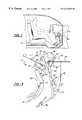
- FIG. 1is a fragmentary view of the subject invention installed in an automotive vehicle
- FIG. 2is a perspective view of a first embodiment of the subject invention
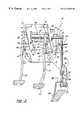
- FIG. 3is a side elevational view of the embodiment of FIG. 1 in a first position of adjustment
- FIG. 4is a side elevational view of the embodiment of FIG. 1 in a second position of adjustment
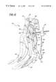
- FIG. 5is a perspective view of a second embodiment of the subject invention.
- FIG. 6is a schematic view taken from the right side of FIG. 5;
- FIG. 7is a schematic view taken from the left side of FIG. 5 .
- FIGS. 1 through 4two embodiments of an adjustable pedal assembly are shown, one generally at 10 in FIGS. 1 through 4 and the second generally at 110 in FIGS. 5 through 7.
- Like or corresponding components or partsare indicated with like numerals differing by 100 .
- Each assembly 10 and 110includes a mounting bracket 12 and 112 for attachment to a vehicle structure 13 .
- the occupant seat 15may be stationary relative to the vehicle structure 13 and the subject invention allows the pedal assemblies 10 and 110 to adjust the operating position of the pedals relative to the seat, i.e., the pedal assemblies 10 and 110 are adjusted in and out, i.e., forward and rearward, to adjust for occupants with different leg lengths or seating positions. In other words, instead of adjusting the position of the seat, the position of the pedals is adjusted.
- Each assembly 10 and 110includes a first pedal lever 14 and 114 having an upper end 16 and 116 and a lower pad end 18 and 118 .
- a linkage mechanismsupports the pedal lever 14 and 114 for operative pivotal movement relative to the bracket 12 and 112 in an operational position and supports an element connection 20 and 120 for movement during the operative pivotal movement and for adjustment of the operational position of the pad end 18 and 118 relative to the bracket 12 and 112 (between full lines and phantom lines) while limiting movement of the element connection 20 and 120 relative to the bracket 12 and 112 during the adjustment.
- the motion transmitting element connection 20 and 120attaches to and moves a motion transmitting element, like a cable or rod 19 and 119 , which is usually supplied by the automobile manufacturer and attaches to one of the clutch, brake or throttle control of a vehicle.
- the linkage mechanismincludes an adjustment link 22 and 122 pivotally supported by the bracket 12 and 112 at one end thereof and extending to a distal end.
- the upper end 16 and 116 of the first pedal lever 14 and 114is pivotally attached at a first pivot joint or axis 24 and 124 to the distal end of the adjustment link 22 and 122 .
- a drag link 26 and 126is pivotally connected to the first pedal lever 14 and 114 at a pivot joint or axis 27 and 127 for moving the element connection 20 and 120 during the operative pivotal movement of the first pedal lever 14 and 114 .
- An actuator link 28 and 128is pivotally attached at a pivot joint or axis 29 and 129 to the bracket 12 and 112 and extends to a stabilizing or lower end.
- the drag link 26 and 126is pivotally connected at a first end via a pivot joint or axis 30 and 130 to the actuator link 28 and 128 , the pivot joint or axis 30 in the first embodiment coinciding with the element connection 20 .
- the element connection 20 and 120is disposed on the actuator link 28 and 128 .
- the assembly 10 and 110includes a second pedal lever 32 and 132 having upper 34 and 134 and lower 36 and 136 ends.
- the assembly 10 and 110is characterized by a control link 42 and 142 connecting the second pedal lever 32 and 132 to the linkage mechanism for adjusting the operational position of the operational axis 40 and 140 of the second pedal lever 32 and 132 in response to the adjustment of the operational position of the pad end 18 and 118 of the first pedal lever 14 and 114 relative to the bracket 12 and 112 , and a guide 38 and 138 supported by the bracket 12 and 112 for guiding movement of the operational axis 40 and 140 of the second pedal lever 32 and 132 during the adjustment thereof.
- the guide 38 and 138comprises a guide link pivotally connected to the bracket 12 and 112 for pivotal movement about a pivot joint or an adjustment axis 39 and 139 and pivotally supports the second pedal lever 32 and 132 for pivotal movement about an operational axis 40 and 140 .
- the control link 42 and 142 and the upper end 16 and 116 of the first pedal lever 14 and 114are pivotally attached to the distal end of the adjustment link 22 and 122 .
- the control link 42 and the upper end 16 of the first pedal lever 14are pivotally attached to the distal end of the adjustment link 22 on different axes, 24 and 43 , respectively, the axis 43 being defined by a pin extending laterally through a slot 47 in a flange of the bracket 12 .
- control link 142 and the upper end 116 of the first pedal lever 114are operatively or pivotally interconnected to the distal end of the adjustment link 122 on a common axis 124 , e.g., by a common pin. It will be appreciated that the control link 42 and 142 may be operatively interrelated or interconnected with the movement of adjustment link 22 and 122 by various mechanisms so long as they move in unison.
- the upper end 34 and 134 of the second pedal lever 32 and 132extends above the operational axis 40 and 140 and the lower end 36 and 136 of the second pedal lever 32 and 132 extends below the operational axis 40 and 140 .
- the upper end 34 and 134 of the second pedal lever 32 and 132includes a vehicle system connection comprising a slot 44 and 144 (as shown in FIGS. 2 and 5) which remains substantially stationary or experiences limited movement during the adjustment.
- a cable 45may be connected to the vehicle system connection 44 and 144 .
- a pedal padis attached to the lower end 36 and 136 of the second pedal lever 32 and 132
- the position of the pad end 18 and 118 of the first pedal lever 14 and 114may be adjusted by pivoting the adjustment link 22 and 122 relative to the bracket 12 and 112 as the drag link 26 and 126 pivots relative to the actuator link 28 and 128 .
- the control link 42 and 142pivots the guide link 38 and 138 about the adjustment axis 39 and 139 without moving the actuator link 28 and 128 to limit movement of the element connection 20 and 120 and/or the vehicle system connection 44 and 144 during such adjustment.
- the position of both of the first pedal lever 14 and 114 and the second pedal lever 32 and 132occurs simultaneously or as one adjustment whereas the normal operation of the respective levers is independent of the other.
- the element connection 20 and 120is moved by pivoting the first pedal lever 14 and 114 relative to the adjustment link 22 and 122 to pivot the actuator link 28 and 128 via the drag link 26 and 126 .
- the vehicle system connection 44 and 144is moved during pivotal movement of the second pedal lever 32 and 132 about the operational axis 40 and 140 .
- the adjustment link 22 and 122may be pivoted relative to the bracket 12 and 112 between a plurality of operational positions.
- a drive mechanism 46 and 146is attached to the bracket 12 and 112 for pivoting the adjustment link 22 and 122 relative to the bracket 12 and 112 between the operational positions.
- the drive mechanism 46 and 146holds the adjustment link 22 and 122 in the selected adjustment position.
- the drive mechanism 46 and 146comprises a worm gear arrangement rotated by an electric motor 52 and 152 .
- the bracket 12 and 112includes a main body or upper portion having a pair of parallel flanges for supporting the adjustment link 22 and 122 .
- An arm 48 and 148extends downwardly and laterally of the upper portion to a support end 50 and 150 .
- the guide link 38 and 138is supported at the support end 50 and 150 of the arm 48 and 148 .
- the first pivot joint or axis 24 and 124is defined by a tube extending between two parallel adjustment links 22 .
- the tubemay be rotatably supported by the adjustment links 22 and the first pedal lever 14 welded thereto, or the tube may be welded to the adjustment links 22 with the pedal lever rotatable relative thereto, as by being supported on a rod extending within the tube.
- the actuator link 28is secured to a tube defining the pivot axis 29 , this tube being rotatable relative to the adjustment links 22 .
- the first embodimentalso includes a third pedal lever 60 .
- the third pedal lever 60is pivotally attached to its adjustment link 62 via a pivot axis of tube 64 .
- the adjustment link 62is pivotally attached to the bracket 12 on the same axis 29 but on the opposite side of one of the flanges of the bracket 12 .
- a drag link 66connects the third pedal lever 60 to a control rod 67 , which would be attached to the clutch mechanism of a vehicle.
- An actuator link(not shown) interconnects a pivot axis or tube 69 and the drag link 66 .
- the third pedal lever mechanismoperates in the same general manner as the first pedal lever mechanism.
Landscapes
- Physics & Mathematics (AREA)
- General Physics & Mathematics (AREA)
- Engineering & Computer Science (AREA)
- Automation & Control Theory (AREA)
- Mechanical Control Devices (AREA)
- Auxiliary Drives, Propulsion Controls, And Safety Devices (AREA)
Abstract
Description
Claims (11)
Priority Applications (1)
| Application Number | Priority Date | Filing Date | Title |
|---|---|---|---|
| US09/461,466US6173625B1 (en) | 1999-12-14 | 1999-12-14 | Adjustable multi-pedal assembly |
Applications Claiming Priority (1)
| Application Number | Priority Date | Filing Date | Title |
|---|---|---|---|
| US09/461,466US6173625B1 (en) | 1999-12-14 | 1999-12-14 | Adjustable multi-pedal assembly |
Publications (1)
| Publication Number | Publication Date |
|---|---|
| US6173625B1true US6173625B1 (en) | 2001-01-16 |
Family
ID=23832675
Family Applications (1)
| Application Number | Title | Priority Date | Filing Date |
|---|---|---|---|
| US09/461,466Expired - Fee RelatedUS6173625B1 (en) | 1999-12-14 | 1999-12-14 | Adjustable multi-pedal assembly |
Country Status (1)
| Country | Link |
|---|---|
| US (1) | US6173625B1 (en) |
Cited By (27)
| Publication number | Priority date | Publication date | Assignee | Title |
|---|---|---|---|---|
| WO2002019051A1 (en)* | 2000-08-28 | 2002-03-07 | Grand Haven Stamped Products | Adjustable pedal apparatus for vehicles |
| US6443028B1 (en)* | 2000-10-02 | 2002-09-03 | General Motors Corporation | Adjustable control pedal assembly for motor vehicle |
| US20020166408A1 (en)* | 2001-05-09 | 2002-11-14 | Willemsen Larry G. | Pedal adjuster |
| US20020189909A1 (en)* | 1999-03-02 | 2002-12-19 | Buckley James A. | Suspended pedal system for golf cars |
| US20030064859A1 (en)* | 2001-10-01 | 2003-04-03 | St. Pierre John C. | Clutch pedal assembly |
| US6564672B2 (en) | 2000-05-15 | 2003-05-20 | Grand Haven Stamped Products, Division Of Jsj Corporation | Adjustable pedal apparatus |
| US6581491B2 (en) | 2001-02-13 | 2003-06-24 | Grand Haven Stamped Products, Division Of Jsj Corporation | Pedal with tongued connection for improved torsional strength |
| US6619155B2 (en) | 2000-05-15 | 2003-09-16 | Grand Haven Stamped Products, Division Of Jsj Corporation | Adjustable pedal apparatus |
| US6655231B2 (en) | 2001-02-21 | 2003-12-02 | Ksr Industrial Corporation | Pedal adjuster for electronic throttle control |
| US6782774B2 (en)* | 2000-08-11 | 2004-08-31 | Aisin Seiki Kabushiki Kaisha | Pedal apparatus for automobile |
| US20040182193A1 (en)* | 2001-08-08 | 2004-09-23 | Jean-Marc Attard | Pedal support with coupled functions |
| US20040239090A1 (en)* | 2003-01-31 | 2004-12-02 | Riefe Richard K. | Linear tracking column module |
| US20040250646A1 (en)* | 2003-06-13 | 2004-12-16 | Gordon Smith | Adjustable pedal system having a slot-link mechanism |
| US6862950B2 (en) | 2001-11-02 | 2005-03-08 | Ksr Industrial Corporation | Adjustable pedal assembly |
| US20050241431A1 (en)* | 2002-09-27 | 2005-11-03 | Continental Teves Ag & Co. Ohg | Adjustable pedal device |
| US20060248978A1 (en)* | 2002-11-22 | 2006-11-09 | Jaume Prat Terradas | Ratio regulation mechanism for an action lever |
| US20070295146A1 (en)* | 2006-05-30 | 2007-12-27 | Honda Motor Co., Ltd. | Anteroposterior position variable pedal apparatus |
| EP1428094A4 (en)* | 2001-08-31 | 2008-04-23 | Ksr Ind Corp | Adjustable control vehicle pedal |
| US7530289B2 (en) | 2004-01-23 | 2009-05-12 | Ksr Technologies Co. | Manual adjustable pedal assembly |
| US8069750B2 (en) | 2007-08-09 | 2011-12-06 | Ksr Technologies Co. | Compact pedal assembly with improved noise control |
| US20130133471A1 (en)* | 2011-11-30 | 2013-05-30 | Magna Closures Inc. | Adjustable pedal assembly with swing arm |
| US9163707B2 (en) | 2011-09-30 | 2015-10-20 | Mtd Products Inc | Method for controlling the speed of a self-propelled walk-behind lawn mower |
| US9387835B2 (en) | 2012-08-14 | 2016-07-12 | Kongsberg Power Products Systems I, Inc. | Pedal apparatus for a vehicle |
| USD903556S1 (en) | 2018-08-10 | 2020-12-01 | Ka Group Ag | Pedal apparatus |
| USD913877S1 (en) | 2018-08-10 | 2021-03-23 | Ka Group Ag | Pedal apparatus |
| USD916632S1 (en) | 2018-08-10 | 2021-04-20 | Ka Group Ag | Pedal apparatus |
| USD917354S1 (en) | 2018-08-10 | 2021-04-27 | Ka Group Ag | Pedal apparatus |
Citations (12)
| Publication number | Priority date | Publication date | Assignee | Title |
|---|---|---|---|---|
| US3319487A (en) | 1964-01-09 | 1967-05-16 | Gen Motors Corp | Vehicle control pedals |
| US3511109A (en) | 1968-10-14 | 1970-05-12 | Gen Motors Corp | Adjustable control pedals |
| US3563111A (en) | 1968-07-24 | 1971-02-16 | Gen Motors Corp | Adjustable control pedals |
| US3643524A (en) | 1970-05-26 | 1972-02-22 | Gen Motors Corp | Control pedals for vehicles |
| US3643525A (en) | 1970-05-26 | 1972-02-22 | Gen Motors Corp | Adjustable control pedals for vehicles |
| US3691868A (en) | 1971-07-06 | 1972-09-19 | Raymond P Smith | Adjustable pedal |
| US3828625A (en)* | 1971-11-19 | 1974-08-13 | Grand Haven Stamped Prod | Adjustable linkage |
| US4683977A (en) | 1985-05-15 | 1987-08-04 | Thomas Murphy | Adjustable pedal assembly |
| US4870871A (en) | 1987-05-22 | 1989-10-03 | Wickes Manufacturing Company | Adjustable accelerator and brake pedal mechanism |
| US5172606A (en)* | 1992-03-25 | 1992-12-22 | General Motors Corporation | Module cockpit/support structure with adjustable pedals |
| US5460061A (en) | 1993-09-17 | 1995-10-24 | Comfort Pedals, Inc. | Adjustable control pedal apparatus |
| US5855143A (en) | 1997-11-25 | 1999-01-05 | Ford Global Technologies, Inc. | Adjustable pedal apparatus |
- 1999
- 1999-12-14USUS09/461,466patent/US6173625B1/ennot_activeExpired - Fee Related
Patent Citations (12)
| Publication number | Priority date | Publication date | Assignee | Title |
|---|---|---|---|---|
| US3319487A (en) | 1964-01-09 | 1967-05-16 | Gen Motors Corp | Vehicle control pedals |
| US3563111A (en) | 1968-07-24 | 1971-02-16 | Gen Motors Corp | Adjustable control pedals |
| US3511109A (en) | 1968-10-14 | 1970-05-12 | Gen Motors Corp | Adjustable control pedals |
| US3643524A (en) | 1970-05-26 | 1972-02-22 | Gen Motors Corp | Control pedals for vehicles |
| US3643525A (en) | 1970-05-26 | 1972-02-22 | Gen Motors Corp | Adjustable control pedals for vehicles |
| US3691868A (en) | 1971-07-06 | 1972-09-19 | Raymond P Smith | Adjustable pedal |
| US3828625A (en)* | 1971-11-19 | 1974-08-13 | Grand Haven Stamped Prod | Adjustable linkage |
| US4683977A (en) | 1985-05-15 | 1987-08-04 | Thomas Murphy | Adjustable pedal assembly |
| US4870871A (en) | 1987-05-22 | 1989-10-03 | Wickes Manufacturing Company | Adjustable accelerator and brake pedal mechanism |
| US5172606A (en)* | 1992-03-25 | 1992-12-22 | General Motors Corporation | Module cockpit/support structure with adjustable pedals |
| US5460061A (en) | 1993-09-17 | 1995-10-24 | Comfort Pedals, Inc. | Adjustable control pedal apparatus |
| US5855143A (en) | 1997-11-25 | 1999-01-05 | Ford Global Technologies, Inc. | Adjustable pedal apparatus |
Cited By (42)
| Publication number | Priority date | Publication date | Assignee | Title |
|---|---|---|---|---|
| US20020189909A1 (en)* | 1999-03-02 | 2002-12-19 | Buckley James A. | Suspended pedal system for golf cars |
| US6840352B2 (en)* | 1999-03-02 | 2005-01-11 | Textron Inc. | Suspended pedal system for golf cars |
| US20040003675A1 (en)* | 2000-05-15 | 2004-01-08 | Brock Robert D. | Adjustable pedal apparatus |
| US6564672B2 (en) | 2000-05-15 | 2003-05-20 | Grand Haven Stamped Products, Division Of Jsj Corporation | Adjustable pedal apparatus |
| US6925905B2 (en) | 2000-05-15 | 2005-08-09 | Grand Haven Stamped Products, Divison Of Jsj Corporation | Adjustable pedal apparatus |
| US6619155B2 (en) | 2000-05-15 | 2003-09-16 | Grand Haven Stamped Products, Division Of Jsj Corporation | Adjustable pedal apparatus |
| US6782774B2 (en)* | 2000-08-11 | 2004-08-31 | Aisin Seiki Kabushiki Kaisha | Pedal apparatus for automobile |
| WO2002019051A1 (en)* | 2000-08-28 | 2002-03-07 | Grand Haven Stamped Products | Adjustable pedal apparatus for vehicles |
| US6443028B1 (en)* | 2000-10-02 | 2002-09-03 | General Motors Corporation | Adjustable control pedal assembly for motor vehicle |
| US6581491B2 (en) | 2001-02-13 | 2003-06-24 | Grand Haven Stamped Products, Division Of Jsj Corporation | Pedal with tongued connection for improved torsional strength |
| US20040007085A1 (en)* | 2001-02-21 | 2004-01-15 | Ksr Industrial Corporation | Adjustable brake and throttle pedal assembly |
| US6655231B2 (en) | 2001-02-21 | 2003-12-02 | Ksr Industrial Corporation | Pedal adjuster for electronic throttle control |
| US6792827B2 (en) | 2001-02-21 | 2004-09-21 | Ksr Industrial Corporation | Adjustable brake and throttle pedal assembly |
| US20020166408A1 (en)* | 2001-05-09 | 2002-11-14 | Willemsen Larry G. | Pedal adjuster |
| US7114411B2 (en) | 2001-05-09 | 2006-10-03 | Ksr Industrial Corporation | Pedal adjuster |
| US6990875B2 (en)* | 2001-08-08 | 2006-01-31 | Robert Bosch Corporation | Pedal support with coupled functions |
| US20040182193A1 (en)* | 2001-08-08 | 2004-09-23 | Jean-Marc Attard | Pedal support with coupled functions |
| EP1428094A4 (en)* | 2001-08-31 | 2008-04-23 | Ksr Ind Corp | Adjustable control vehicle pedal |
| US6592494B2 (en)* | 2001-10-01 | 2003-07-15 | Daimlerchrysler Corporation | Clutch pedal assembly |
| US20030064859A1 (en)* | 2001-10-01 | 2003-04-03 | St. Pierre John C. | Clutch pedal assembly |
| US6862950B2 (en) | 2001-11-02 | 2005-03-08 | Ksr Industrial Corporation | Adjustable pedal assembly |
| US20050241431A1 (en)* | 2002-09-27 | 2005-11-03 | Continental Teves Ag & Co. Ohg | Adjustable pedal device |
| US20070266816A1 (en)* | 2002-09-27 | 2007-11-22 | Ralf Jakobi | Adjustable pedal device |
| US20060248978A1 (en)* | 2002-11-22 | 2006-11-09 | Jaume Prat Terradas | Ratio regulation mechanism for an action lever |
| US7421927B2 (en)* | 2002-11-22 | 2008-09-09 | Fico Cables, S.A. | Ratio regulation mechanism for an action lever |
| US7063354B2 (en) | 2003-01-31 | 2006-06-20 | Delphi Technologies, Inc. | Linear tracking column module |
| US20040239090A1 (en)* | 2003-01-31 | 2004-12-02 | Riefe Richard K. | Linear tracking column module |
| US20040250646A1 (en)* | 2003-06-13 | 2004-12-16 | Gordon Smith | Adjustable pedal system having a slot-link mechanism |
| US7140270B2 (en)* | 2003-06-13 | 2006-11-28 | Dura Global Technologies, Inc. | Adjustable pedal system having a slot-link mechanism |
| US7530289B2 (en) | 2004-01-23 | 2009-05-12 | Ksr Technologies Co. | Manual adjustable pedal assembly |
| US20070295146A1 (en)* | 2006-05-30 | 2007-12-27 | Honda Motor Co., Ltd. | Anteroposterior position variable pedal apparatus |
| US7424836B2 (en)* | 2006-05-30 | 2008-09-16 | Honda Motor Co., Ltd. | Anteroposterior position variable pedal apparatus |
| US8069750B2 (en) | 2007-08-09 | 2011-12-06 | Ksr Technologies Co. | Compact pedal assembly with improved noise control |
| US9163707B2 (en) | 2011-09-30 | 2015-10-20 | Mtd Products Inc | Method for controlling the speed of a self-propelled walk-behind lawn mower |
| US9651138B2 (en) | 2011-09-30 | 2017-05-16 | Mtd Products Inc. | Speed control assembly for a self-propelled walk-behind lawn mower |
| US9791037B2 (en) | 2011-09-30 | 2017-10-17 | Mtd Products Inc | Speed control assembly for a self-propelled walk-behind lawn mower |
| US20130133471A1 (en)* | 2011-11-30 | 2013-05-30 | Magna Closures Inc. | Adjustable pedal assembly with swing arm |
| US9387835B2 (en) | 2012-08-14 | 2016-07-12 | Kongsberg Power Products Systems I, Inc. | Pedal apparatus for a vehicle |
| USD903556S1 (en) | 2018-08-10 | 2020-12-01 | Ka Group Ag | Pedal apparatus |
| USD913877S1 (en) | 2018-08-10 | 2021-03-23 | Ka Group Ag | Pedal apparatus |
| USD916632S1 (en) | 2018-08-10 | 2021-04-20 | Ka Group Ag | Pedal apparatus |
| USD917354S1 (en) | 2018-08-10 | 2021-04-27 | Ka Group Ag | Pedal apparatus |
Similar Documents
| Publication | Publication Date | Title |
|---|---|---|
| US6173625B1 (en) | Adjustable multi-pedal assembly | |
| US6758115B2 (en) | Adjustable brake, clutch and accelerator pedals | |
| US6840130B2 (en) | Adjustable brake, clutch and accelerator pedals | |
| US6019015A (en) | Adjustable accelerator pedal | |
| US6701799B2 (en) | Adjustable automobile pedal system | |
| US6305239B1 (en) | Adjustable pedal assembly | |
| US6289761B1 (en) | Automatic adjustable brake, clutch and accelerator pedals | |
| US7051613B2 (en) | Adjustable pedal assembly | |
| US5996438A (en) | Adjustable accelerator pedal | |
| US5086663A (en) | Adjustable pedal | |
| US6516683B2 (en) | Electric adjustable pedal system with mechanical active lock-up | |
| US3563111A (en) | Adjustable control pedals | |
| CA2297336C (en) | Adjustable automobile pedal system | |
| JPH028557A (en) | Remote control mechanism | |
| US6609438B1 (en) | Electric adjustable pedal system with two-piece upper arm | |
| US7832305B2 (en) | Adjustable pedal system with low brake ratio change | |
| US20040083846A1 (en) | Adjustable pedal mechanism with tapered rivet for automatic gap and wear protection | |
| EP1428094B1 (en) | Adjustable control vehicle pedal | |
| GB2290509A (en) | Hand controls, for disabled drivers, mounted on adjustable steering column | |
| AU2001293238A1 (en) | Adjustable control vehicle pedal | |
| WO2002045999A2 (en) | Adjustable pedal apparatus with defined adjustment path | |
| MXPA00000724A (en) | Adjustable pedal assembly with electronic throttle control |
Legal Events
| Date | Code | Title | Description |
|---|---|---|---|
| AS | Assignment | Owner name:TELEELEX INCORPORATED, PENNSYLVANIA Free format text:ASSIGNMENT OF ASSIGNORS INTEREST;ASSIGNORS:MCFARLANE, JEFFREY A.;O'NEILL, MICHAEL JARRES;REEL/FRAME:010739/0947;SIGNING DATES FROM 20000322 TO 20000324 | |
| FEPP | Fee payment procedure | Free format text:PAYOR NUMBER ASSIGNED (ORIGINAL EVENT CODE: ASPN); ENTITY STATUS OF PATENT OWNER: LARGE ENTITY Free format text:PAYER NUMBER DE-ASSIGNED (ORIGINAL EVENT CODE: RMPN); ENTITY STATUS OF PATENT OWNER: LARGE ENTITY | |
| AS | Assignment | Owner name:TECHNOLOGY HOLDING COMPANY, DELAWARE Free format text:ASSIGNMENT OF ASSIGNORS INTEREST;ASSIGNOR:TELEFLEX INCORPORATED;REEL/FRAME:013403/0085 Effective date:20020927 | |
| FPAY | Fee payment | Year of fee payment:4 | |
| AS | Assignment | Owner name:WELLS FARGO FOOTHILL, INC., AS AGENT, GEORGIA Free format text:SECURITY AGREEMENT;ASSIGNOR:DRIVESOL WORLDWIDE, INC.;REEL/FRAME:016769/0421 Effective date:20051108 | |
| AS | Assignment | Owner name:DRIVESOL WORLDWIDE, INC., MICHIGAN Free format text:ASSIGNMENT OF ASSIGNORS INTEREST;ASSIGNORS:TELEFLEX INCORPORATED;TELEFLEX HOLDING COMPANY;TELEFLEX HOLDING COMPANY II;AND OTHERS;REEL/FRAME:017262/0061 Effective date:20050812 | |
| FPAY | Fee payment | Year of fee payment:8 | |
| AS | Assignment | Owner name:SUN DRIVESOL FINANCE, LLC, FLORIDA Free format text:SECURITY AGREEMENT;ASSIGNORS:DRIVESOL INTERMEDIATE HOLDING CORP.;DRIVESOL WORLDWIDE, INC.;DRIVESOL AUTOMOTIVE INCORPORATED;AND OTHERS;REEL/FRAME:021158/0208 Effective date:20080625 | |
| AS | Assignment | Owner name:SUN DRIVESOL FINANCE, LLC, FLORIDA Free format text:AMENDED AND RESTATED PATENT SECURITY AGREEMENT;ASSIGNORS:DRIVESOL INTERMEDIATE HOLDING CORP.;DRIVESOL WORLDWIDE, INC.;DRIVESOL AUTOMOTIVE INCORPORATED;AND OTHERS;REEL/FRAME:021561/0335 Effective date:20080919 | |
| AS | Assignment | Owner name:DRIVESOL WORLDWIDE, INC., MICHIGAN Free format text:RELEASE BY SECURED PARTY;ASSIGNOR:WELLS FARGO FOOTHILL, INC., AS AGENT;REEL/FRAME:022542/0868 Effective date:20090409 | |
| FEPP | Fee payment procedure | Free format text:PAYOR NUMBER ASSIGNED (ORIGINAL EVENT CODE: ASPN); ENTITY STATUS OF PATENT OWNER: LARGE ENTITY Free format text:PAYER NUMBER DE-ASSIGNED (ORIGINAL EVENT CODE: RMPN); ENTITY STATUS OF PATENT OWNER: LARGE ENTITY | |
| REMI | Maintenance fee reminder mailed | ||
| LAPS | Lapse for failure to pay maintenance fees | ||
| STCH | Information on status: patent discontinuation | Free format text:PATENT EXPIRED DUE TO NONPAYMENT OF MAINTENANCE FEES UNDER 37 CFR 1.362 | |
| FP | Lapsed due to failure to pay maintenance fee | Effective date:20130116 |