US6173411B1 - Method and system for fault-tolerant network connection switchover - Google Patents
Method and system for fault-tolerant network connection switchoverDownload PDFInfo
- Publication number
- US6173411B1 US6173411B1US09/059,896US5989698AUS6173411B1US 6173411 B1US6173411 B1US 6173411B1US 5989698 AUS5989698 AUS 5989698AUS 6173411 B1US6173411 B1US 6173411B1
- Authority
- US
- United States
- Prior art keywords
- node
- connection
- network
- computer
- port
- Prior art date
- Legal status (The legal status is an assumption and is not a legal conclusion. Google has not performed a legal analysis and makes no representation as to the accuracy of the status listed.)
- Expired - Lifetime
Links
- 238000000034methodMethods0.000titleclaimsdescription41
- 238000004891communicationMethods0.000claimsdescription6
- 230000000737periodic effectEffects0.000claimsdescription4
- 230000007613environmental effectEffects0.000claimsdescription3
- 238000012360testing methodMethods0.000abstractdescription9
- 230000004044responseEffects0.000abstractdescription5
- 238000010586diagramMethods0.000description5
- 230000009471actionEffects0.000description3
- 238000005516engineering processMethods0.000description3
- 230000008569processEffects0.000description3
- 238000013507mappingMethods0.000description2
- 238000012986modificationMethods0.000description2
- 230000004048modificationEffects0.000description2
- 241000238876AcariSpecies0.000description1
- 230000005540biological transmissionEffects0.000description1
- 230000008859changeEffects0.000description1
- 230000007812deficiencyEffects0.000description1
- 238000013461designMethods0.000description1
- 230000006870functionEffects0.000description1
- 238000012423maintenanceMethods0.000description1
- 230000006855networkingEffects0.000description1
- 230000008520organizationEffects0.000description1
- 230000002093peripheral effectEffects0.000description1
- 238000011084recoveryMethods0.000description1
Images


Classifications
- H—ELECTRICITY
- H04—ELECTRIC COMMUNICATION TECHNIQUE
- H04L—TRANSMISSION OF DIGITAL INFORMATION, e.g. TELEGRAPHIC COMMUNICATION
- H04L41/00—Arrangements for maintenance, administration or management of data switching networks, e.g. of packet switching networks
- H04L41/06—Management of faults, events, alarms or notifications
- H04L41/0654—Management of faults, events, alarms or notifications using network fault recovery
- H04L41/0668—Management of faults, events, alarms or notifications using network fault recovery by dynamic selection of recovery network elements, e.g. replacement by the most appropriate element after failure
- H—ELECTRICITY
- H04—ELECTRIC COMMUNICATION TECHNIQUE
- H04L—TRANSMISSION OF DIGITAL INFORMATION, e.g. TELEGRAPHIC COMMUNICATION
- H04L43/00—Arrangements for monitoring or testing data switching networks
- H04L43/08—Monitoring or testing based on specific metrics, e.g. QoS, energy consumption or environmental parameters
- H04L43/0805—Monitoring or testing based on specific metrics, e.g. QoS, energy consumption or environmental parameters by checking availability
- H04L43/0811—Monitoring or testing based on specific metrics, e.g. QoS, energy consumption or environmental parameters by checking availability by checking connectivity
- H—ELECTRICITY
- H04—ELECTRIC COMMUNICATION TECHNIQUE
- H04L—TRANSMISSION OF DIGITAL INFORMATION, e.g. TELEGRAPHIC COMMUNICATION
- H04L43/00—Arrangements for monitoring or testing data switching networks
- H04L43/50—Testing arrangements
- H—ELECTRICITY
- H04—ELECTRIC COMMUNICATION TECHNIQUE
- H04L—TRANSMISSION OF DIGITAL INFORMATION, e.g. TELEGRAPHIC COMMUNICATION
- H04L45/00—Routing or path finding of packets in data switching networks
- H04L45/22—Alternate routing
Definitions
- the present inventionrelates, in general, to fault-tolerant computing. More specifically, the present invention relates to methods and systems for quickly switching between network connections.
- connection between a single computer and a networkis a critical point of failure. That is, often a computer is connected to a network by a single physical connection. Thus, if that connection were to break, all connectivity to and from the particular computer would be lost. Multiple connections from a single computer to a network have therefore been implemented, but not without problems.
- FIG. 1a diagram of a computer 11 connected to a network 21 is shown.
- Computer 11includes a network interface, for example, a fast-Ethernet interface 13 .
- a connection 30links fast-Ethernet interface 13 with a fault-tolerant transceiver 15 .
- Fault tolerant transceiver 15establishes a connection between connection 30 and one of two connections 29 and 31 to respective fast-Ethernet switches 19 and 17 (these “switches” as used herein are SNMP managed network Switches). Switches 17 and 19 are connected in a fault-tolerant matter to network 21 through connections 23 and 25 .
- Fault-tolerant transceiver 15may be purchased from a number of vendors including, for example, a Digi brand, model MIL-240TX redundant port selector; while fast-Ethernet switches 17 and 19 may also be purchased from a number of vendors and may include, for example, a Cisco brand, model 5000 series fast-Ethernet switch.
- trafficnormally passes from fast-Ethernet interface 13 through fault-tolerant transceiver 15 , and over a primary connection 29 or 31 to respective switch 17 or 19 and on to network 21 .
- the other of connections 29 and 31remains inactive.
- Network 21 and switches 17 and 19maintain routing information that directs traffic bound for computer 11 through the above-described primary route.
- fault-tolerant transceiver 15will switch traffic to the other of connection 29 and 31 . For example, if the primary connection was 31 , and connection 31 broke, fault-tolerant transceiver 15 would switch traffic to connection 29 .
- fault-tolerant transceiver 15is only sensitive to a loss of the physical receive signal on the wire pair from the switches (e.g., 17 and 19 ) to the transceivers. It is not sensitive to a break in the separate wire pair from the transceiver to the switch. Also, it is sensitive only to the signal from the switch to which it is directly attached and does not test the backup link for latent failures which would prevent a successful recovery. This technique also fails to test the switches themselves.
- FIG. 2Another example of a previous technique for connecting a computer 11 to a network 21 is shown in FIG. 2 .
- Network switches 17 and 19 and their connection to each other and network 21is similar to that shown in FIG. 1 .
- each of switchese.g., 17 and 19
- connects to its own fast-Ethernet interfacee.g., 13 and 14 .
- the present inventionis directed toward solutions to the above-identified problems.
- the present inventionincludes a method for managing network routing in a system including a first node, a second node and a third node.
- the first nodehas primary and secondary connections to the second and third nodes, respectively.
- the second and third nodesare connected by a network.
- the methodincludes periodically communicating between the first and the second or third node over at least the primary connection. A status of network connectivity between the communicating nodes is thereby determined.
- roles of the primary and secondary connectionsare swapped to establish new primary and secondary connections.
- a messageis then sent with an origin address of the first node to the second node over the new primary connection.
- the origin address of this messagefacilitates the network nodes learning about routing to the first node over the new primary connection.
- the first nodemay include a first port connected to the primary connection and a second port connected to the secondary connection.
- the first and second portshave first and second network addresses, respectively; and the first node has a system network address.
- the periodic communicationmay be transmitted from the first port of the first node with an origin address of the first port. Further, the origin address of the message sent if network connectivity was unacceptable may be the system network address of the first node. Also, the periodic communication may be a ping message having the first network address of the first port as its origin address. This ping message may be destined for the second or third node.
- the methodmay include swapping the roles of the primary and secondary connections and pinging the second node over the new primary link.
- the status of the connection between the second port and the other of the second and third nodes to which the previous ping was sentis determined.
- the present inventionincludes a system for implementing methods corresponding to those described hereandabove.
- a link managermay be attached to the computer and may provide connectivity between the computer and the primary and secondary connections.
- the link managermay be, for example, integral with the computer (e.g., on a main board of the computer), on an expansion board of the computer, or external to the computer.
- the computermay be an operator workstation or a controller such as, for example, an industrial or environmental controller.
- FIGS. 1 - 2depict prior art systems for managing fault-tolerant network connections
- FIG. 3depicts a fault-tolerant network connection topology in accordance with one embodiment of the present invention
- FIG. 4is a functional block diagram of the link manager of FIG. 3 in accordance with one embodiment of the present invention.
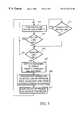
- FIGS. 5 - 7are flow-diagrams of techniques in accordance with one embodiment of the present invention.
- FIGS. 8 - 11depict several topologies in conformance with the techniques of the present invention.
- depicted hereinare techniques for establishing a fault-tolerant connection to a network that overcome the disadvantages of prior techniques discussed hereinabove. That is, according to the present invention, connectivity problems are quickly detected, and upon assumption of an alternate (back-up) connection, network reroute times are mitigated.
- a fast-Ethernet interface 13is connected to both a link manager 33 and a CPU 31 .
- the topological relationship between fast-Ethernet interface 13 , link manager 33 and CPU 31will vary with implementation requirements. Several example topologies are discussed hereinbelow in regard to FIGS. 9 - 11 ; however, many other topologies will become apparent to those of ordinary skill in the art in view of the disclosure herein.
- the techniques disclosed hereinare not limited to fast-Ethernet technology.
- Other networking technologiesmay be subjected to the techniques disclosed herein, such as, for example, conventional Ethernet technology.
- Link manager 33is connected to both fast-Ethernet interface 13 and CPU 31 .
- the connection to fast-Ethernet interface 13is that which would be normally used for network connectivity.
- the connection of link manager 33 to CPU 31is for configuration and control purposes.
- link manager 33 and fast-Ethernet interface 13may each be PCI cards within a personal computer architecture. In this example, their connections to CPU 31 are by way of the PCI bus.
- a cablemay connect fast-Ethernet interface 13 and link manager 33 .
- Two network connections 29 and 31(for example, fast-Ethernet connections) couple link manager 33 to switches 19 and 17 , respectively.
- Connections 23 and 25couple switches 17 and 19 to network 21 , which connects them to each other.
- Link manager 33is more specifically depicted in FIG. 4.
- a fast-Ethernet interface 41provides connectivity (e.g., PCI bus interface) with an attached host computer.
- Computer interface 45also attaches to the host computer and facilitates configuration and control of link manager 33 .
- Fast-Ethernet interfaces 47 and 49provide redundant network connectivity.
- logic 43interconnects the above-described elements.
- logic 43is implemented as an ASIC; however, the particular implementation of logic 43 will vary with product requirements.
- logic 43could be implemented using a programmed processor, a field programmable gate array, or any other form of logic that may be configured to perform the tasks disclosed therefor herein.
- the techniques of the present inventionsend test messages across each connection of the link manager to the attached switches.
- a break in a connection, or faulty connectionis detected upon a failed response to one of the test messages.
- trafficis routed across the remaining good connection.
- a test messageis sent across the now active connection bound for the switch connected to the inactive connection. This message traverses both switches causing each to learn the new routing. Rerouting is therefore accomplished quickly.
- FIGS. 5 - 6depict flow-diagrams of operational techniques in accordance with one embodiment the present invention.
- the link managerpings a switch connected to the primary, active connection, every T p seconds, STEP 101 .
- the ping messagecontains a source address unique to the link manager port currently associated with the active connection. If the active connection is ok, pinging thereof continues, STEP 101 . Also, a check is regularly performed to detect a loss of receive signal on the active connection interface, STEP 113 .
- a testis performed to check whether the back-up connection status is good, STEP 105 . If the back-up connection is unavailable, no further action can be taken and pinging of the primary connection continues in anticipation of either restoration of the active connection or availability of the back-up connection. Also under this condition, the host computer may be notified such that it may take appropriate action, such as, e.g., to enter a fail-safe condition.
- the link manageris configured to direct traffic through the back-up connection, STEP 107 . Further, a ping message is sent from the link manager, through the switch connected to the back-up connection and to the switch connected to the primary, failed, connection, STEP 109 . This ping message contains a source address of the computer connected to the link manager. As a result, the switches connected to the primary and back-up connections are made aware of the new routing to the computer. This facilitates the immediate routing of traffic bound for the computer over the back-up, secondary, connection. Lastly, the roles of active and backup connections are swapped and the process iterates, STEP 111 .
- FIG. 6a flow-diagram depicts a technique for maintaining the status of the back-up connection.
- a pingis send over the back-up connection to its respective switch every T p seconds, STEP 115 .
- the ping messagecontains a source address unique to the link manager port currently associated with the backup connection. If the back-up connection is good, that is, the ping is responded to timely, STEP 117 ; then the back-up connection status is set to good, STEP 119 . If the response to the ping message is not timely received, the back-up connection status is set to bad, STEP 121 (A maintenance alert may also be generated.
- the inventionfacilitates detecting latent faults in unused paths and repairing them within the MTBF of a primary fault.) In either case, the processor iterates to the pinging step, STEP 115 .
- ping messagesare sent from the link manager, across each connection to the switch attached thereto. Failure of these ping messages will indicate failure of the link the ping message was sent across.
- ping messagesare sent across each link, but are bound for the switch connected to the other connection. Thus, the ping message must traverse one switch to get to the destination switch, traversing both the connection from the link manager to the immediately attached switch and across the connection between the switches.
- this embodimentcontains example information on how timed message transmission can be implemented using a common clock.
- the pings sent from each porthave a unique source address for that particular port.
- the final ping, once the port roles are swappeduses the source address of the attached computer system.
- a clock tickis awaited, STEP 201 .
- Clock ticksare used as the basis for timing operations described herein. If a clock tick has not occurred, no action is taken. However, if a clock tick has occurred a first counter is decremented, STEP 203 . This first counter is designed to expire, on a 0.5 second basis (of course, this time can be adjusted for particular application requirements).
- a ping messageis sent from the active port to the standby switch using the address of the active port, STEPS 205 , 207 . If the ping is successful, STEP 209 , a second counter with a 30 second interval is decremented, STEP 211 . The second counter decrement is also performed if the first counter decrement did not result in the 0.5 second time period expiring, STEP 205 . If the second counter has not expired, STEP 213 , then the process iterates awaiting a next clock tick, STEP 201 .
- a pingis sent from the standby port to the active switch using the standby port's address, STEP 215 . If the ping was successful, STEP 217 then the process iterates awaiting another clock tick, STEP 201 .
- the techniques of the present inventionmay be implemented in different topologies. As examples, several of these topologies are depicted in FIGS. 8 - 11 .
- the computer depictedmay be, for example, a workstation, an embedded processor, a controller, (e.g., industrial or environmental) or other computer type.
- a computer 11is depicted and contains fast-Ethernet interface 13 and link manager 33 connected by cable 30 . Connections 29 and 31 couple the system to a network.
- computer 11is a PCI bus-based computer and fast Ethernet interface 13 and link manager 33 are PCI interface cards. In another embodiment, all circuitry may be on a common board (e.g., the system motherboard).
- link manager 33 and fast-Ethernet interface 13have been integrated onto a single interface card.
- this cardmay interface with its host computer using a PCI bus.
- fast-Ethernet interface 13is incorporated on a main board (e.g., a motherboard) of computer 11 .
- Link manager 33is a peripheral (e.g., PCI) interface card.
- fast-Ethernet interface 13may be incorporated on a main board of computer 11 or as a separate interface card.
- Link manager 33is disposed external to computer 11 and is connected thereto by connections 30 and 63 .
- Connection 63is particularly used for command and control of link manager 33 and interfaces with computer 11 through a communications port 61 (e.g., a serial or parallel port).
Landscapes
- Engineering & Computer Science (AREA)
- Computer Networks & Wireless Communication (AREA)
- Signal Processing (AREA)
- Environmental & Geological Engineering (AREA)
- Small-Scale Networks (AREA)
Abstract
Description
Claims (19)
Priority Applications (5)
| Application Number | Priority Date | Filing Date | Title |
|---|---|---|---|
| US09/059,896US6173411B1 (en) | 1997-10-21 | 1998-04-14 | Method and system for fault-tolerant network connection switchover |
| PCT/US1998/021984WO1999021322A2 (en) | 1997-10-20 | 1998-10-16 | Method and system for fault-tolerant network connection switchover |
| AU10990/99AAU1099099A (en) | 1997-10-20 | 1998-10-16 | Method and system for fault-tolerant network connection switchover |
| DE69828810TDE69828810T2 (en) | 1997-10-20 | 1998-10-16 | METHOD AND SYSTEM FOR ERROR-TOLERANT NETWORK INTERCONNECTION SWITCHING |
| EP98953670AEP1025680B1 (en) | 1997-10-20 | 1998-10-16 | Method and system for fault-tolerant network connection switchover |
Applications Claiming Priority (3)
| Application Number | Priority Date | Filing Date | Title |
|---|---|---|---|
| US6298497P | 1997-10-21 | 1997-10-21 | |
| US6268197P | 1997-10-22 | 1997-10-22 | |
| US09/059,896US6173411B1 (en) | 1997-10-21 | 1998-04-14 | Method and system for fault-tolerant network connection switchover |
Publications (1)
| Publication Number | Publication Date |
|---|---|
| US6173411B1true US6173411B1 (en) | 2001-01-09 |
Family
ID=27369758
Family Applications (1)
| Application Number | Title | Priority Date | Filing Date |
|---|---|---|---|
| US09/059,896Expired - LifetimeUS6173411B1 (en) | 1997-10-20 | 1998-04-14 | Method and system for fault-tolerant network connection switchover |
Country Status (1)
| Country | Link |
|---|---|
| US (1) | US6173411B1 (en) |
Cited By (66)
| Publication number | Priority date | Publication date | Assignee | Title |
|---|---|---|---|---|
| US20020010750A1 (en)* | 2000-04-28 | 2002-01-24 | Airsys Atm Sa | Redundant input/output management device, notably for data routing |
| US20020085631A1 (en)* | 2000-08-18 | 2002-07-04 | Engwer Darwin A. | Method, apparatus, and system for managing data compression in a wireless network |
| US20030037276A1 (en)* | 2001-06-01 | 2003-02-20 | Fujitsu Networks | System and method to perform non-service effecting bandwidth reservation using a reservation signaling protocol |
| US6535991B1 (en)* | 2000-01-12 | 2003-03-18 | Worldcom, Inc. | Method and apparatus for providing reliable communications in an intelligent network |
| US6546498B1 (en)* | 1998-12-02 | 2003-04-08 | Nec Corporation | System and process for detecting/eliminating faulty port in fiber channel-arbitrated loop |
| US6580898B1 (en)* | 1999-05-17 | 2003-06-17 | Toshitaka Oguri | Supervisory system and method |
| US6581166B1 (en)* | 1999-03-02 | 2003-06-17 | The Foxboro Company | Network fault detection and recovery |
| US20030115368A1 (en)* | 2001-12-14 | 2003-06-19 | D-Link Corporation | Apparatus for multi-level loopback test in a community network system and method therefor |
| US20030133712A1 (en)* | 2002-01-11 | 2003-07-17 | Nec Corporation | Multiplex communication system and method |
| US20030193895A1 (en)* | 2000-08-18 | 2003-10-16 | Engwer Darwin A. | Seamless roaming options in an IEEE 802.11 compliant network |
| US6718383B1 (en) | 2000-06-02 | 2004-04-06 | Sun Microsystems, Inc. | High availability networking with virtual IP address failover |
| US6728780B1 (en) | 2000-06-02 | 2004-04-27 | Sun Microsystems, Inc. | High availability networking with warm standby interface failover |
| US6732186B1 (en) | 2000-06-02 | 2004-05-04 | Sun Microsystems, Inc. | High availability networking with quad trunking failover |
| EP1422870A1 (en)* | 2002-10-24 | 2004-05-26 | Tellabs Oy | Method and system for detecting a connection fault |
| US20040100562A1 (en)* | 2002-11-21 | 2004-05-27 | Hitachi, Ltd. | Transmitting device, video camera device, transmitting method for the transmitting device, and transmitting method for the video camera device |
| US6763479B1 (en)* | 2000-06-02 | 2004-07-13 | Sun Microsystems, Inc. | High availability networking with alternate pathing failover |
| US6804712B1 (en)* | 2000-06-30 | 2004-10-12 | Cisco Technology, Inc. | Identifying link failures in a network |
| US20040240422A1 (en)* | 2003-05-30 | 2004-12-02 | Samsung Electronics Co., Ltd. | Method for wireless local area network communication using multiple channels |
| US20040264388A1 (en)* | 2003-06-30 | 2004-12-30 | Rover Jeremy L. | System and method for dynamically configuring and transitioning wired and wireless networks |
| US20040267923A1 (en)* | 2003-06-30 | 2004-12-30 | Rover Jeremy L. | System and method for programmatically changing the network location of a network component |
| US20040267921A1 (en)* | 2003-06-30 | 2004-12-30 | Rover Jeremy L. | System and method for describing network components and their associations |
| US20040267922A1 (en)* | 2003-06-30 | 2004-12-30 | Rover Jeremy L. | System and method for the design and description of networks |
| US20040267949A1 (en)* | 2003-06-30 | 2004-12-30 | Rover Jeremy L. | System and method for synchronous configuration of DHCP server and router interfaces |
| US20050050379A1 (en)* | 2001-12-07 | 2005-03-03 | Invensys Systems, Inc. | Method and apparatus for network fault correction via adaptive fault router |
| US6904458B1 (en)* | 2000-04-26 | 2005-06-07 | Microsoft Corporation | System and method for remote management |
| US6931441B1 (en) | 2001-06-29 | 2005-08-16 | Cisco Technology, Inc. | Method and apparatus for managing a network using link state information |
| US6965558B1 (en)* | 2001-08-23 | 2005-11-15 | Cisco Technology, Inc. | Method and system for protecting a network interface |
| US6976071B1 (en)* | 2000-05-03 | 2005-12-13 | Nortel Networks Limited | Detecting if a secure link is alive |
| US20050281190A1 (en)* | 2004-06-17 | 2005-12-22 | Mcgee Michael S | Automated recovery from a split segment condition in a layer2 network for teamed network resources of a computer systerm |
| US20060020698A1 (en)* | 2004-07-21 | 2006-01-26 | Whipple William R | Method and system for managing connections |
| US7020709B1 (en)* | 2000-06-30 | 2006-03-28 | Intel Corporation | System and method for fault tolerant stream splitting |
| US20060077891A1 (en)* | 2004-10-07 | 2006-04-13 | Cisco Technology, Inc. | Wiring closet redundancy |
| EP1727309A1 (en)* | 2005-05-27 | 2006-11-29 | Alcatel | Methods and apparatus for monitoring link integrity for signaling traffic over a path traversing hybrid ATM/ethernet infrastructure in support of packet voice service provisioning |
| US20060294579A1 (en)* | 2004-03-01 | 2006-12-28 | Invensys Systems, Inc. | Process control methods and apparatus for intrusion detection, protection and network hardening |
| US20070127365A1 (en)* | 2005-12-07 | 2007-06-07 | Yong Tae | Method for implementing redundant structure of ATCA (advanced telecom computing architecture) system via base interface and the ATCA system for use in the same |
| US20070140109A1 (en)* | 2003-12-12 | 2007-06-21 | Norbert Lobig | Method for protection switching of geographically separate switching systems |
| US20070192501A1 (en)* | 2006-01-30 | 2007-08-16 | Juniper Networks, Inc. | Determining connectivity status for unnumbered inerfaces of a target network device |
| US7280495B1 (en) | 2000-08-18 | 2007-10-09 | Nortel Networks Limited | Reliable broadcast protocol in a wireless local area network |
| US7308279B1 (en) | 2000-08-18 | 2007-12-11 | Nortel Networks Limited | Dynamic power level control on transmitted messages in a wireless LAN |
| EP1428133A4 (en)* | 2001-06-05 | 2007-12-26 | Ericsson Ab | ETHERNET PROTECTION SYSTEM |
| US7339892B1 (en) | 2000-08-18 | 2008-03-04 | Nortel Networks Limited | System and method for dynamic control of data packet fragmentation threshold in a wireless network |
| US20090116405A1 (en)* | 2005-06-29 | 2009-05-07 | Abb Oy | Redundant Automation Data Communications Network |
| US20090274068A1 (en)* | 2005-11-30 | 2009-11-05 | Koestner Michael | Network Having Redundancy Properties, Ethernet Switch for Such a Network and Method for Configuring Such a Network |
| US20090274104A1 (en)* | 2008-05-01 | 2009-11-05 | Honeywell International Inc. | Fixed mobile convergence techniques for redundant alarm reporting |
| US7769021B1 (en)* | 2004-07-03 | 2010-08-03 | At&T Corp. | Multiple media fail-over to alternate media |
| US7860857B2 (en) | 2006-03-30 | 2010-12-28 | Invensys Systems, Inc. | Digital data processing apparatus and methods for improving plant performance |
| US20110209148A1 (en)* | 2010-02-25 | 2011-08-25 | Fujitsu Limited | Information processing device, virtual machine connection method, program, and recording medium |
| US8339973B1 (en) | 2010-09-07 | 2012-12-25 | Juniper Networks, Inc. | Multicast traceroute over MPLS/BGP IP multicast VPN |
| US20130088952A1 (en)* | 2011-10-05 | 2013-04-11 | Sivaram Balasubramanian | Multiple-Fault-Tolerant Ethernet Network for Industrial Control |
| US8472346B1 (en) | 2007-06-08 | 2013-06-25 | Juniper Networks, Inc. | Failure detection for tunneled label-switched paths |
| US20130297976A1 (en)* | 2012-05-04 | 2013-11-07 | Paraccel, Inc. | Network Fault Detection and Reconfiguration |
| US8797886B1 (en) | 2006-01-30 | 2014-08-05 | Juniper Networks, Inc. | Verification of network paths using two or more connectivity protocols |
| US20140337529A1 (en)* | 2013-05-13 | 2014-11-13 | Vmware, Inc. | Placing a network device into a maintenance mode in a virtualized computing environment |
| US8902780B1 (en) | 2012-09-26 | 2014-12-02 | Juniper Networks, Inc. | Forwarding detection for point-to-multipoint label switched paths |
| US8953460B1 (en) | 2012-12-31 | 2015-02-10 | Juniper Networks, Inc. | Network liveliness detection using session-external communications |
| US20150106514A1 (en)* | 2011-09-26 | 2015-04-16 | Theranos, Inc. | Methods and Systems for Network Connectivity |
| US9258234B1 (en) | 2012-12-28 | 2016-02-09 | Juniper Networks, Inc. | Dynamically adjusting liveliness detection intervals for periodic network communications |
| US9596156B2 (en) | 2011-09-26 | 2017-03-14 | Theranos, Inc. | Network connectivity methods and systems |
| US9769017B1 (en) | 2014-09-26 | 2017-09-19 | Juniper Networks, Inc. | Impending control plane disruption indication using forwarding plane liveliness detection protocols |
| US10116544B2 (en) | 2016-06-21 | 2018-10-30 | Juniper Networks, Inc. | Extended ping protocol for determining status for remote interfaces without requiring network reachability |
| US10374936B2 (en) | 2015-12-30 | 2019-08-06 | Juniper Networks, Inc. | Reducing false alarms when using network keep-alive messages |
| US10397085B1 (en) | 2016-06-30 | 2019-08-27 | Juniper Networks, Inc. | Offloading heartbeat responses message processing to a kernel of a network device |
| US10554520B2 (en)* | 2017-04-03 | 2020-02-04 | Datrium, Inc. | Data path monitoring in a distributed storage network |
| US11750441B1 (en) | 2018-09-07 | 2023-09-05 | Juniper Networks, Inc. | Propagating node failure errors to TCP sockets |
| US12160362B2 (en) | 2017-03-27 | 2024-12-03 | Juniper Networks, Inc. | Traceroute for multi-path routing |
| WO2025012964A1 (en)* | 2023-07-13 | 2025-01-16 | Jio Platforms Limited | Method and system for message routing management |
Citations (21)
| Publication number | Priority date | Publication date | Assignee | Title |
|---|---|---|---|---|
| US4692918A (en)* | 1984-12-17 | 1987-09-08 | At&T Bell Laboratories | Reliable local data network arrangement |
| US4710926A (en) | 1985-12-27 | 1987-12-01 | American Telephone And Telegraph Company, At&T Bell Laboratories | Fault recovery in a distributed processing system |
| US4787082A (en) | 1986-07-24 | 1988-11-22 | American Telephone And Telegraph Company, At&T Bell Laboratories | Data flow control arrangement for local area network |
| US4964120A (en) | 1989-09-08 | 1990-10-16 | Honeywell Inc. | Method of detecting a cable fault and switching to a redundant cable in a universal local area network |
| US5153874A (en) | 1989-07-10 | 1992-10-06 | Kabushiki Kaisha Toshiba | Redundancy data transmission device |
| US5159685A (en)* | 1989-12-06 | 1992-10-27 | Racal Data Communications Inc. | Expert system for communications network |
| US5218600A (en) | 1989-06-19 | 1993-06-08 | Richard Hirschmann Gmbh & Co. | Process for networking computers and/or computer networks and networking systems |
| US5276440A (en) | 1989-02-16 | 1994-01-04 | International Business Machines Corporation | Network device information exchange |
| US5329521A (en) | 1992-11-12 | 1994-07-12 | Walsh Jeffrey R | Method and apparatus for redundant local area network systems |
| US5341496A (en) | 1990-08-29 | 1994-08-23 | The Foxboro Company | Apparatus and method for interfacing host computer and computer nodes using redundant gateway data lists of accessible computer node data |
| US5390326A (en) | 1993-04-30 | 1995-02-14 | The Foxboro Company | Local area network with fault detection and recovery |
| US5485465A (en) | 1992-05-20 | 1996-01-16 | The Whitaker Corporation | Redundancy control for a broadcast data transmission system |
| US5485576A (en) | 1994-01-28 | 1996-01-16 | Fee; Brendan | Chassis fault tolerant system management bus architecture for a networking |
| US5493650A (en) | 1994-03-02 | 1996-02-20 | Synoptics Communications, Inc. | Apparatus and method for monitoring the presence of cables connected to ports of a computer network controller and automatically reconfiguring the network when cables are connected to or removed from the controller |
| US5508997A (en) | 1994-07-04 | 1996-04-16 | Fujitsu Limited | Bus communication method and bus communication system |
| US5508998A (en) | 1995-02-28 | 1996-04-16 | Synoptics Communications, Inc. | Remote token ring beacon station detection and isolation |
| US5586112A (en) | 1993-12-16 | 1996-12-17 | Nec Corporation | Digital crossconnect system for selecting alternate communication routes in case of a transmission fault |
| US5661719A (en) | 1995-10-19 | 1997-08-26 | Ncr Corporation | Method for activating a backup network management station in a network management system |
| US5675723A (en) | 1995-05-19 | 1997-10-07 | Compaq Computer Corporation | Multi-server fault tolerance using in-band signalling |
| US5680437A (en) | 1996-06-04 | 1997-10-21 | Motorola, Inc. | Signaling system seven distributed call terminating processor |
| US5987521A (en)* | 1995-07-10 | 1999-11-16 | International Business Machines Corporation | Management of path routing in packet communications networks |
- 1998
- 1998-04-14USUS09/059,896patent/US6173411B1/ennot_activeExpired - Lifetime
Patent Citations (22)
| Publication number | Priority date | Publication date | Assignee | Title |
|---|---|---|---|---|
| US4692918A (en)* | 1984-12-17 | 1987-09-08 | At&T Bell Laboratories | Reliable local data network arrangement |
| US4710926A (en) | 1985-12-27 | 1987-12-01 | American Telephone And Telegraph Company, At&T Bell Laboratories | Fault recovery in a distributed processing system |
| US4787082A (en) | 1986-07-24 | 1988-11-22 | American Telephone And Telegraph Company, At&T Bell Laboratories | Data flow control arrangement for local area network |
| US5276440A (en) | 1989-02-16 | 1994-01-04 | International Business Machines Corporation | Network device information exchange |
| US5218600A (en) | 1989-06-19 | 1993-06-08 | Richard Hirschmann Gmbh & Co. | Process for networking computers and/or computer networks and networking systems |
| US5153874A (en) | 1989-07-10 | 1992-10-06 | Kabushiki Kaisha Toshiba | Redundancy data transmission device |
| US4964120A (en) | 1989-09-08 | 1990-10-16 | Honeywell Inc. | Method of detecting a cable fault and switching to a redundant cable in a universal local area network |
| US5337320A (en)* | 1989-12-06 | 1994-08-09 | Racal-Datacom, Inc. | Semi-automatic mode of network design |
| US5159685A (en)* | 1989-12-06 | 1992-10-27 | Racal Data Communications Inc. | Expert system for communications network |
| US5341496A (en) | 1990-08-29 | 1994-08-23 | The Foxboro Company | Apparatus and method for interfacing host computer and computer nodes using redundant gateway data lists of accessible computer node data |
| US5485465A (en) | 1992-05-20 | 1996-01-16 | The Whitaker Corporation | Redundancy control for a broadcast data transmission system |
| US5329521A (en) | 1992-11-12 | 1994-07-12 | Walsh Jeffrey R | Method and apparatus for redundant local area network systems |
| US5390326A (en) | 1993-04-30 | 1995-02-14 | The Foxboro Company | Local area network with fault detection and recovery |
| US5586112A (en) | 1993-12-16 | 1996-12-17 | Nec Corporation | Digital crossconnect system for selecting alternate communication routes in case of a transmission fault |
| US5485576A (en) | 1994-01-28 | 1996-01-16 | Fee; Brendan | Chassis fault tolerant system management bus architecture for a networking |
| US5493650A (en) | 1994-03-02 | 1996-02-20 | Synoptics Communications, Inc. | Apparatus and method for monitoring the presence of cables connected to ports of a computer network controller and automatically reconfiguring the network when cables are connected to or removed from the controller |
| US5508997A (en) | 1994-07-04 | 1996-04-16 | Fujitsu Limited | Bus communication method and bus communication system |
| US5508998A (en) | 1995-02-28 | 1996-04-16 | Synoptics Communications, Inc. | Remote token ring beacon station detection and isolation |
| US5675723A (en) | 1995-05-19 | 1997-10-07 | Compaq Computer Corporation | Multi-server fault tolerance using in-band signalling |
| US5987521A (en)* | 1995-07-10 | 1999-11-16 | International Business Machines Corporation | Management of path routing in packet communications networks |
| US5661719A (en) | 1995-10-19 | 1997-08-26 | Ncr Corporation | Method for activating a backup network management station in a network management system |
| US5680437A (en) | 1996-06-04 | 1997-10-21 | Motorola, Inc. | Signaling system seven distributed call terminating processor |
Non-Patent Citations (1)
| Title |
|---|
| Stevens, et al. "TCP/IP Illustrated, vol. 1. The Protocols," TCP/IP Illustrated vol. 1, XP-002106390, pp. 85-96. |
Cited By (105)
| Publication number | Priority date | Publication date | Assignee | Title |
|---|---|---|---|---|
| US6546498B1 (en)* | 1998-12-02 | 2003-04-08 | Nec Corporation | System and process for detecting/eliminating faulty port in fiber channel-arbitrated loop |
| US6581166B1 (en)* | 1999-03-02 | 2003-06-17 | The Foxboro Company | Network fault detection and recovery |
| US6580898B1 (en)* | 1999-05-17 | 2003-06-17 | Toshitaka Oguri | Supervisory system and method |
| US6535991B1 (en)* | 2000-01-12 | 2003-03-18 | Worldcom, Inc. | Method and apparatus for providing reliable communications in an intelligent network |
| US6904458B1 (en)* | 2000-04-26 | 2005-06-07 | Microsoft Corporation | System and method for remote management |
| US20020010750A1 (en)* | 2000-04-28 | 2002-01-24 | Airsys Atm Sa | Redundant input/output management device, notably for data routing |
| US7707281B2 (en)* | 2000-04-28 | 2010-04-27 | Airsys Atm S.A. | Redundant input/output management device, notably for data routing |
| US6976071B1 (en)* | 2000-05-03 | 2005-12-13 | Nortel Networks Limited | Detecting if a secure link is alive |
| US6763479B1 (en)* | 2000-06-02 | 2004-07-13 | Sun Microsystems, Inc. | High availability networking with alternate pathing failover |
| US6718383B1 (en) | 2000-06-02 | 2004-04-06 | Sun Microsystems, Inc. | High availability networking with virtual IP address failover |
| US6728780B1 (en) | 2000-06-02 | 2004-04-27 | Sun Microsystems, Inc. | High availability networking with warm standby interface failover |
| US6732186B1 (en) | 2000-06-02 | 2004-05-04 | Sun Microsystems, Inc. | High availability networking with quad trunking failover |
| US7020709B1 (en)* | 2000-06-30 | 2006-03-28 | Intel Corporation | System and method for fault tolerant stream splitting |
| US6804712B1 (en)* | 2000-06-30 | 2004-10-12 | Cisco Technology, Inc. | Identifying link failures in a network |
| US7339892B1 (en) | 2000-08-18 | 2008-03-04 | Nortel Networks Limited | System and method for dynamic control of data packet fragmentation threshold in a wireless network |
| US7308279B1 (en) | 2000-08-18 | 2007-12-11 | Nortel Networks Limited | Dynamic power level control on transmitted messages in a wireless LAN |
| US20030193895A1 (en)* | 2000-08-18 | 2003-10-16 | Engwer Darwin A. | Seamless roaming options in an IEEE 802.11 compliant network |
| US7366103B2 (en) | 2000-08-18 | 2008-04-29 | Nortel Networks Limited | Seamless roaming options in an IEEE 802.11 compliant network |
| US7280495B1 (en) | 2000-08-18 | 2007-10-09 | Nortel Networks Limited | Reliable broadcast protocol in a wireless local area network |
| US6947483B2 (en) | 2000-08-18 | 2005-09-20 | Nortel Networks Limited | Method, apparatus, and system for managing data compression in a wireless network |
| US20020085631A1 (en)* | 2000-08-18 | 2002-07-04 | Engwer Darwin A. | Method, apparatus, and system for managing data compression in a wireless network |
| US7289429B2 (en) | 2001-06-01 | 2007-10-30 | Fujitsu Network Communications, Inc. | System and method to perform non-service effecting bandwidth reservation using a reservation signaling protocol |
| WO2002099570A3 (en)* | 2001-06-01 | 2003-04-03 | Fujitsu Network Communications | System and method to perform non-service effecting bandwidth reservation using a reservation signaling protocol |
| US20030037276A1 (en)* | 2001-06-01 | 2003-02-20 | Fujitsu Networks | System and method to perform non-service effecting bandwidth reservation using a reservation signaling protocol |
| EP1428133A4 (en)* | 2001-06-05 | 2007-12-26 | Ericsson Ab | ETHERNET PROTECTION SYSTEM |
| US6931441B1 (en) | 2001-06-29 | 2005-08-16 | Cisco Technology, Inc. | Method and apparatus for managing a network using link state information |
| US6965558B1 (en)* | 2001-08-23 | 2005-11-15 | Cisco Technology, Inc. | Method and system for protecting a network interface |
| US7380154B2 (en)* | 2001-12-07 | 2008-05-27 | Invensys Systems, Inc. | Method and apparatus for network fault correction via adaptive fault router |
| US20050050379A1 (en)* | 2001-12-07 | 2005-03-03 | Invensys Systems, Inc. | Method and apparatus for network fault correction via adaptive fault router |
| US20030115368A1 (en)* | 2001-12-14 | 2003-06-19 | D-Link Corporation | Apparatus for multi-level loopback test in a community network system and method therefor |
| US7010595B2 (en)* | 2001-12-14 | 2006-03-07 | D-Link Corp. | Apparatus for multi-level loopback test in a community network system and method therefor |
| US20030133712A1 (en)* | 2002-01-11 | 2003-07-17 | Nec Corporation | Multiplex communication system and method |
| US7372804B2 (en)* | 2002-01-11 | 2008-05-13 | Nec Corporation | Multiplex communication system and method |
| US7609728B2 (en) | 2002-01-11 | 2009-10-27 | Nec Corporation | Optical transmission switching device |
| US20060072923A1 (en)* | 2002-01-11 | 2006-04-06 | Nec Corporation | Optical transmission switching device |
| US20070271484A1 (en)* | 2002-10-24 | 2007-11-22 | Tellabs Oy | Method, system and network entity for detecting a connection fault |
| US7296177B2 (en) | 2002-10-24 | 2007-11-13 | Tellabs Oy | Method, system, and network entity for detecting a connection fault |
| US20040133368A1 (en)* | 2002-10-24 | 2004-07-08 | Tellabs Oy | Method, system, and network entity for detecting a connection fault |
| EP1422870A1 (en)* | 2002-10-24 | 2004-05-26 | Tellabs Oy | Method and system for detecting a connection fault |
| US20040100562A1 (en)* | 2002-11-21 | 2004-05-27 | Hitachi, Ltd. | Transmitting device, video camera device, transmitting method for the transmitting device, and transmitting method for the video camera device |
| US20040240422A1 (en)* | 2003-05-30 | 2004-12-02 | Samsung Electronics Co., Ltd. | Method for wireless local area network communication using multiple channels |
| US7489674B2 (en)* | 2003-05-30 | 2009-02-10 | Samsung Electronics Co., Ltd. | Method for wireless local area network communication using multiple channels |
| US7383340B2 (en)* | 2003-06-30 | 2008-06-03 | Intel Corporation | System and method for programmatically changing the network location of a network component |
| US7483390B2 (en) | 2003-06-30 | 2009-01-27 | Intel Corporation | System and method for dynamically configuring and transitioning wired and wireless networks |
| US20040264388A1 (en)* | 2003-06-30 | 2004-12-30 | Rover Jeremy L. | System and method for dynamically configuring and transitioning wired and wireless networks |
| US20040267923A1 (en)* | 2003-06-30 | 2004-12-30 | Rover Jeremy L. | System and method for programmatically changing the network location of a network component |
| US20040267921A1 (en)* | 2003-06-30 | 2004-12-30 | Rover Jeremy L. | System and method for describing network components and their associations |
| US20040267949A1 (en)* | 2003-06-30 | 2004-12-30 | Rover Jeremy L. | System and method for synchronous configuration of DHCP server and router interfaces |
| US20040267922A1 (en)* | 2003-06-30 | 2004-12-30 | Rover Jeremy L. | System and method for the design and description of networks |
| US7386629B2 (en) | 2003-06-30 | 2008-06-10 | Intel Corporation | System and method for synchronous configuration of DHCP server and router interfaces |
| US20070140109A1 (en)* | 2003-12-12 | 2007-06-21 | Norbert Lobig | Method for protection switching of geographically separate switching systems |
| US8089980B2 (en) | 2003-12-12 | 2012-01-03 | Siemens Aktiengesellschaft | Method for protection switching of geographically separate switching systems |
| US20060294579A1 (en)* | 2004-03-01 | 2006-12-28 | Invensys Systems, Inc. | Process control methods and apparatus for intrusion detection, protection and network hardening |
| US7761923B2 (en) | 2004-03-01 | 2010-07-20 | Invensys Systems, Inc. | Process control methods and apparatus for intrusion detection, protection and network hardening |
| US20050281190A1 (en)* | 2004-06-17 | 2005-12-22 | Mcgee Michael S | Automated recovery from a split segment condition in a layer2 network for teamed network resources of a computer systerm |
| US7990849B2 (en)* | 2004-06-17 | 2011-08-02 | Hewlett-Packard Development Company, L.P. | Automated recovery from a split segment condition in a layer2 network for teamed network resources of a computer system |
| US7769021B1 (en)* | 2004-07-03 | 2010-08-03 | At&T Corp. | Multiple media fail-over to alternate media |
| US8934349B2 (en) | 2004-07-03 | 2015-01-13 | At&T Intellectual Property Ii, L.P. | Multiple media fail-over to alternate media |
| US8737232B2 (en) | 2004-07-03 | 2014-05-27 | At&T Intellectual Property Ii, L.P. | Multiple media fail-over to alternate media |
| US8385351B1 (en) | 2004-07-03 | 2013-02-26 | At&T Intellectual Property Ii, L.P. | Multiple media fail-over to alternate media |
| US20060020698A1 (en)* | 2004-07-21 | 2006-01-26 | Whipple William R | Method and system for managing connections |
| US8825832B2 (en)* | 2004-07-21 | 2014-09-02 | Hewlett-Packard Development Company, L.P. | Method and system for managing connections |
| US8259562B2 (en)* | 2004-10-07 | 2012-09-04 | Cisco Technology, Inc. | Wiring closet redundancy |
| US20060077891A1 (en)* | 2004-10-07 | 2006-04-13 | Cisco Technology, Inc. | Wiring closet redundancy |
| EP1727309A1 (en)* | 2005-05-27 | 2006-11-29 | Alcatel | Methods and apparatus for monitoring link integrity for signaling traffic over a path traversing hybrid ATM/ethernet infrastructure in support of packet voice service provisioning |
| US20090116405A1 (en)* | 2005-06-29 | 2009-05-07 | Abb Oy | Redundant Automation Data Communications Network |
| US20090274068A1 (en)* | 2005-11-30 | 2009-11-05 | Koestner Michael | Network Having Redundancy Properties, Ethernet Switch for Such a Network and Method for Configuring Such a Network |
| US8031592B2 (en)* | 2005-11-30 | 2011-10-04 | Siemens Aktiengesellschaft | Network having redundancy properties, Ethernet switch for such a network and method for configuring such a network |
| US7706259B2 (en)* | 2005-12-07 | 2010-04-27 | Electronics And Telecommunications Research Institute | Method for implementing redundant structure of ATCA (advanced telecom computing architecture) system via base interface and the ATCA system for use in the same |
| US20070127365A1 (en)* | 2005-12-07 | 2007-06-07 | Yong Tae | Method for implementing redundant structure of ATCA (advanced telecom computing architecture) system via base interface and the ATCA system for use in the same |
| US8117301B2 (en)* | 2006-01-30 | 2012-02-14 | Juniper Networks, Inc. | Determining connectivity status for unnumbered interfaces of a target network device |
| US8797886B1 (en) | 2006-01-30 | 2014-08-05 | Juniper Networks, Inc. | Verification of network paths using two or more connectivity protocols |
| US20070192501A1 (en)* | 2006-01-30 | 2007-08-16 | Juniper Networks, Inc. | Determining connectivity status for unnumbered inerfaces of a target network device |
| US7860857B2 (en) | 2006-03-30 | 2010-12-28 | Invensys Systems, Inc. | Digital data processing apparatus and methods for improving plant performance |
| US8472346B1 (en) | 2007-06-08 | 2013-06-25 | Juniper Networks, Inc. | Failure detection for tunneled label-switched paths |
| US20090274104A1 (en)* | 2008-05-01 | 2009-11-05 | Honeywell International Inc. | Fixed mobile convergence techniques for redundant alarm reporting |
| US8891525B2 (en)* | 2008-05-01 | 2014-11-18 | Honeywell International Inc. | Fixed mobile convergence techniques for redundant alarm reporting |
| US20110209148A1 (en)* | 2010-02-25 | 2011-08-25 | Fujitsu Limited | Information processing device, virtual machine connection method, program, and recording medium |
| US8339973B1 (en) | 2010-09-07 | 2012-12-25 | Juniper Networks, Inc. | Multicast traceroute over MPLS/BGP IP multicast VPN |
| US9596156B2 (en) | 2011-09-26 | 2017-03-14 | Theranos, Inc. | Network connectivity methods and systems |
| US11323345B2 (en) | 2011-09-26 | 2022-05-03 | Labrador Diagnostics Llc | Methods and systems for network connectivity |
| US10541896B2 (en) | 2011-09-26 | 2020-01-21 | Theranos Ip Company, Llc | Network connectivity methods and systems |
| US20150106514A1 (en)* | 2011-09-26 | 2015-04-16 | Theranos, Inc. | Methods and Systems for Network Connectivity |
| US10425304B2 (en)* | 2011-09-26 | 2019-09-24 | Theranos Ip Company, Llc | Methods and systems for network connectivity |
| EP3483735A1 (en)* | 2011-09-26 | 2019-05-15 | Theranos IP Company, LLC | Network connectivity methods and systems |
| US20130088952A1 (en)* | 2011-10-05 | 2013-04-11 | Sivaram Balasubramanian | Multiple-Fault-Tolerant Ethernet Network for Industrial Control |
| US8670303B2 (en)* | 2011-10-05 | 2014-03-11 | Rockwell Automation Technologies, Inc. | Multiple-fault-tolerant ethernet network for industrial control |
| US20130297976A1 (en)* | 2012-05-04 | 2013-11-07 | Paraccel, Inc. | Network Fault Detection and Reconfiguration |
| US9239749B2 (en)* | 2012-05-04 | 2016-01-19 | Paraccel Llc | Network fault detection and reconfiguration |
| US8902780B1 (en) | 2012-09-26 | 2014-12-02 | Juniper Networks, Inc. | Forwarding detection for point-to-multipoint label switched paths |
| US9781058B1 (en) | 2012-12-28 | 2017-10-03 | Juniper Networks, Inc. | Dynamically adjusting liveliness detection intervals for periodic network communications |
| US9258234B1 (en) | 2012-12-28 | 2016-02-09 | Juniper Networks, Inc. | Dynamically adjusting liveliness detection intervals for periodic network communications |
| US9407526B1 (en) | 2012-12-31 | 2016-08-02 | Juniper Networks, Inc. | Network liveliness detection using session-external communications |
| US8953460B1 (en) | 2012-12-31 | 2015-02-10 | Juniper Networks, Inc. | Network liveliness detection using session-external communications |
| US20140337529A1 (en)* | 2013-05-13 | 2014-11-13 | Vmware, Inc. | Placing a network device into a maintenance mode in a virtualized computing environment |
| US10218622B2 (en)* | 2013-05-13 | 2019-02-26 | Vmware, Inc. | Placing a network device into a maintenance mode in a virtualized computing environment |
| US9769017B1 (en) | 2014-09-26 | 2017-09-19 | Juniper Networks, Inc. | Impending control plane disruption indication using forwarding plane liveliness detection protocols |
| US10374936B2 (en) | 2015-12-30 | 2019-08-06 | Juniper Networks, Inc. | Reducing false alarms when using network keep-alive messages |
| US10116544B2 (en) | 2016-06-21 | 2018-10-30 | Juniper Networks, Inc. | Extended ping protocol for determining status for remote interfaces without requiring network reachability |
| US10397085B1 (en) | 2016-06-30 | 2019-08-27 | Juniper Networks, Inc. | Offloading heartbeat responses message processing to a kernel of a network device |
| US10951506B1 (en) | 2016-06-30 | 2021-03-16 | Juniper Networks, Inc. | Offloading heartbeat responses message processing to a kernel of a network device |
| US12160362B2 (en) | 2017-03-27 | 2024-12-03 | Juniper Networks, Inc. | Traceroute for multi-path routing |
| US10554520B2 (en)* | 2017-04-03 | 2020-02-04 | Datrium, Inc. | Data path monitoring in a distributed storage network |
| US11750441B1 (en) | 2018-09-07 | 2023-09-05 | Juniper Networks, Inc. | Propagating node failure errors to TCP sockets |
| WO2025012964A1 (en)* | 2023-07-13 | 2025-01-16 | Jio Platforms Limited | Method and system for message routing management |
Similar Documents
| Publication | Publication Date | Title |
|---|---|---|
| US6173411B1 (en) | Method and system for fault-tolerant network connection switchover | |
| CN100459601C (en) | Method for realizing active/standby gateway apparatus in network | |
| CA2631023C (en) | Lightweight node based network redundancy solution leveraging rapid spanning tree protocol (rstp) | |
| US6658595B1 (en) | Method and system for asymmetrically maintaining system operability | |
| US6983294B2 (en) | Redundancy systems and methods in communications systems | |
| CN100456694C (en) | Apparatus and method for providing network connectivity | |
| US7969915B2 (en) | Technical enhancements to STP (IEEE 802.1D) implementation | |
| JP4166939B2 (en) | Active fault detection | |
| US8199637B2 (en) | VPLS remote failure indication | |
| JPH07235933A (en) | Fault-torelant connection method and device to local area network of computor system | |
| CN105577444A (en) | Wireless controller management method and wireless controller | |
| WO1999021322A9 (en) | Method and system for fault-tolerant network connection switchover | |
| FI127999B (en) | Redundancy in process control system | |
| CN116248581B (en) | Cloud scene gateway cluster master-slave switching method and system based on SDN | |
| JP2005244672A (en) | Network failure monitoring process system and its method | |
| CN111131035A (en) | Data transmission method and device | |
| CN101958812B (en) | Link failure detection method and system | |
| JP3445900B2 (en) | Internetwork apparatus and network system | |
| JP3504060B2 (en) | Internetwork apparatus and network system | |
| CN110838994B (en) | Link state monitoring method of redundant Ethernet based on broadcast protocol | |
| JP4636247B2 (en) | Packet network and layer 2 switch | |
| JPH1146207A (en) | Inter-lan connector | |
| JP2001308893A (en) | Dynamic reconfiguration system for routing information in loop-type topology network | |
| JPH11296396A (en) | High availability system with switching concealment function | |
| US8406121B2 (en) | Method for error detection in a packet-based message distribution system |
Legal Events
| Date | Code | Title | Description |
|---|---|---|---|
| AS | Assignment | Owner name:FOXBORO COMPANY, THE, MASSACHUSETTS Free format text:ASSIGNMENT OF ASSIGNORS INTEREST;ASSIGNORS:HIRST, MICHAEL D.;GALE, ALAN A.;CUMMINGS, GENE A.;REEL/FRAME:009156/0815;SIGNING DATES FROM 19980407 TO 19980413 | |
| STCF | Information on status: patent grant | Free format text:PATENTED CASE | |
| FEPP | Fee payment procedure | Free format text:PAYOR NUMBER ASSIGNED (ORIGINAL EVENT CODE: ASPN); ENTITY STATUS OF PATENT OWNER: LARGE ENTITY | |
| AS | Assignment | Owner name:INVENSYS SYSTEMS, INC., MASSACHUSETTS Free format text:CHANGE OF NAME;ASSIGNOR:FOXBORO COMPANY, THE;REEL/FRAME:014074/0152 Effective date:20010330 | |
| AS | Assignment | Owner name:DEUTSCHE BANK AG, LONDON, UNITED KINGDOM Free format text:SECURITY INTEREST;ASSIGNOR:INVENSYS SYSTEMS, INC.;REEL/FRAME:015279/0874 Effective date:20040401 Owner name:DEUTSCHE BANK AG, LONDON,UNITED KINGDOM Free format text:SECURITY INTEREST;ASSIGNOR:INVENSYS SYSTEMS, INC.;REEL/FRAME:015279/0874 Effective date:20040401 | |
| FPAY | Fee payment | Year of fee payment:4 | |
| AS | Assignment | Owner name:DEUTSCHE BANK AG, LONDON BRANCH,UNITED KINGDOM Free format text:SECURITY AGREEMENT;ASSIGNOR:INVENSYS SYSTEMS, INC.;REEL/FRAME:017921/0766 Effective date:20060713 Owner name:DEUTSCHE BANK AG, LONDON BRANCH, UNITED KINGDOM Free format text:SECURITY AGREEMENT;ASSIGNOR:INVENSYS SYSTEMS, INC.;REEL/FRAME:017921/0766 Effective date:20060713 | |
| AS | Assignment | Owner name:INVENSYS SYSTEMS, INC., MASSACHUSETTS Free format text:RELEASE AND TERMINATION OF SECURITY INTEREST IN PA;ASSIGNOR:DEUTSCHE BANK AG LONDON;REEL/FRAME:018367/0749 Effective date:20060727 | |
| FPAY | Fee payment | Year of fee payment:8 | |
| FPAY | Fee payment | Year of fee payment:12 | |
| AS | Assignment | Owner name:INVENSYS SYSTEMS, INC., MASSACHUSETTS Free format text:RELEASE BY SECURED PARTY;ASSIGNOR:DEUTSCHE BANK, AG, LONDON BRANCH;REEL/FRAME:030982/0663 Effective date:20080723 | |
| AS | Assignment | Owner name:SCHNEIDER ELECTRIC SYSTEMS USA, INC., MASSACHUSETT Free format text:CHANGE OF NAME;ASSIGNOR:INVENSYS SYSTEMS, INC.;REEL/FRAME:043379/0925 Effective date:20170101 |