US6173119B1 - Camera having radio-frequency identification transponder - Google Patents
Camera having radio-frequency identification transponderDownload PDFInfo
- Publication number
- US6173119B1 US6173119B1US09/372,628US37262899AUS6173119B1US 6173119 B1US6173119 B1US 6173119B1US 37262899 AUS37262899 AUS 37262899AUS 6173119 B1US6173119 B1US 6173119B1
- Authority
- US
- United States
- Prior art keywords
- transponder
- camera
- film
- unit
- inlay
- Prior art date
- Legal status (The legal status is an assumption and is not a legal conclusion. Google has not performed a legal analysis and makes no representation as to the accuracy of the status listed.)
- Expired - Lifetime
Links
Images


Classifications
- B—PERFORMING OPERATIONS; TRANSPORTING
- B65—CONVEYING; PACKING; STORING; HANDLING THIN OR FILAMENTARY MATERIAL
- B65H—HANDLING THIN OR FILAMENTARY MATERIAL, e.g. SHEETS, WEBS, CABLES
- B65H1/00—Supports or magazines for piles from which articles are to be separated
- B65H1/26—Supports or magazines for piles from which articles are to be separated with auxiliary supports to facilitate introduction or renewal of the pile
- B65H1/266—Support fully or partially removable from the handling machine, e.g. cassette, drawer
- G—PHYSICS
- G03—PHOTOGRAPHY; CINEMATOGRAPHY; ANALOGOUS TECHNIQUES USING WAVES OTHER THAN OPTICAL WAVES; ELECTROGRAPHY; HOLOGRAPHY
- G03B—APPARATUS OR ARRANGEMENTS FOR TAKING PHOTOGRAPHS OR FOR PROJECTING OR VIEWING THEM; APPARATUS OR ARRANGEMENTS EMPLOYING ANALOGOUS TECHNIQUES USING WAVES OTHER THAN OPTICAL WAVES; ACCESSORIES THEREFOR
- G03B17/00—Details of cameras or camera bodies; Accessories therefor
- G03B17/18—Signals indicating condition of a camera member or suitability of light
- G—PHYSICS
- G06—COMPUTING OR CALCULATING; COUNTING
- G06K—GRAPHICAL DATA READING; PRESENTATION OF DATA; RECORD CARRIERS; HANDLING RECORD CARRIERS
- G06K19/00—Record carriers for use with machines and with at least a part designed to carry digital markings
- G06K19/06—Record carriers for use with machines and with at least a part designed to carry digital markings characterised by the kind of the digital marking, e.g. shape, nature, code
- G06K19/067—Record carriers with conductive marks, printed circuits or semiconductor circuit elements, e.g. credit or identity cards also with resonating or responding marks without active components
- G06K19/07—Record carriers with conductive marks, printed circuits or semiconductor circuit elements, e.g. credit or identity cards also with resonating or responding marks without active components with integrated circuit chips
- G06K19/077—Constructional details, e.g. mounting of circuits in the carrier
- G06K19/07749—Constructional details, e.g. mounting of circuits in the carrier the record carrier being capable of non-contact communication, e.g. constructional details of the antenna of a non-contact smart card
- G06K19/07758—Constructional details, e.g. mounting of circuits in the carrier the record carrier being capable of non-contact communication, e.g. constructional details of the antenna of a non-contact smart card arrangements for adhering the record carrier to further objects or living beings, functioning as an identification tag
- G—PHYSICS
- G06—COMPUTING OR CALCULATING; COUNTING
- G06K—GRAPHICAL DATA READING; PRESENTATION OF DATA; RECORD CARRIERS; HANDLING RECORD CARRIERS
- G06K19/00—Record carriers for use with machines and with at least a part designed to carry digital markings
- G06K19/06—Record carriers for use with machines and with at least a part designed to carry digital markings characterised by the kind of the digital marking, e.g. shape, nature, code
- G06K19/067—Record carriers with conductive marks, printed circuits or semiconductor circuit elements, e.g. credit or identity cards also with resonating or responding marks without active components
- G06K19/07—Record carriers with conductive marks, printed circuits or semiconductor circuit elements, e.g. credit or identity cards also with resonating or responding marks without active components with integrated circuit chips
- G06K19/077—Constructional details, e.g. mounting of circuits in the carrier
- G06K19/07749—Constructional details, e.g. mounting of circuits in the carrier the record carrier being capable of non-contact communication, e.g. constructional details of the antenna of a non-contact smart card
- G06K19/07773—Antenna details
- G06K19/07777—Antenna details the antenna being of the inductive type
- G06K19/07779—Antenna details the antenna being of the inductive type the inductive antenna being a coil
- G06K19/07783—Antenna details the antenna being of the inductive type the inductive antenna being a coil the coil being planar
- B—PERFORMING OPERATIONS; TRANSPORTING
- B65—CONVEYING; PACKING; STORING; HANDLING THIN OR FILAMENTARY MATERIAL
- B65H—HANDLING THIN OR FILAMENTARY MATERIAL, e.g. SHEETS, WEBS, CABLES
- B65H2405/00—Parts for holding the handled material
- B65H2405/30—Other features of supports for sheets
- B65H2405/31—Supports for sheets fully removable from the handling machine, e.g. cassette
- B65H2405/311—Supports for sheets fully removable from the handling machine, e.g. cassette and serving also as package
- B—PERFORMING OPERATIONS; TRANSPORTING
- B65—CONVEYING; PACKING; STORING; HANDLING THIN OR FILAMENTARY MATERIAL
- B65H—HANDLING THIN OR FILAMENTARY MATERIAL, e.g. SHEETS, WEBS, CABLES
- B65H2511/00—Dimensions; Position; Numbers; Identification; Occurrences
- B65H2511/40—Identification
- B—PERFORMING OPERATIONS; TRANSPORTING
- B65—CONVEYING; PACKING; STORING; HANDLING THIN OR FILAMENTARY MATERIAL
- B65H—HANDLING THIN OR FILAMENTARY MATERIAL, e.g. SHEETS, WEBS, CABLES
- B65H2557/00—Means for control not provided for in groups B65H2551/00 - B65H2555/00
- B65H2557/10—Means for control not provided for in groups B65H2551/00 - B65H2555/00 for signal transmission
Definitions
- the inventionrelates to photography and cameras and more particularly relates to cameras having radio-frequency identification transponders.
- encodementshave been provided on film units and cameras for identification purposes and to convey information about the film unit or camera.
- the term “encodement”is used herein very broadly to cover a feature of physical media used to communicate one or more bits of information to a machine. “Encodement” is inclusive of alphanumeric text and other indicia.
- Type 135 (35 mm) film cassetteshave a “DX” code on the outside surface of the film canister formed by electrically conductive and non-conductive patches.
- This filmalso has optical bar codes, in the form of latent images along longitudinal margins of the filmstrip.
- Advanced Photo SystemTM film cassetteshave magnetic encodements on the film and can have optical encodements identifying print formats. A wide variety of other encodements have been proposed.
- Radio-frequency identification transpondersare widely available in a variety of forms. These devices include a non-volatile memory, such as an EEPROM (Electrically Erasable Programmable Read-Only Memory) semiconductor component integrally contained in the transponder. Stored in the non-volatile memory are encoded data.
- Inlay transpondersare identification transponders that have a substantially flat shape.
- the antenna for an inlay transponderis in the form of a conductive trace deposited on a non-conductive support.
- the antennahas the shape of a flat coil or the like. Leads for the antenna are also deposited, with non-conductive layers interposed as necessary. Memory and any control functions are provided by a chip mounted on the support and operatively connected through the leads to the antenna.
- Inlay transpondershave been used as layers of identification tags and labels to provide encodements that are accessible at a distance.
- the inventionin its broader aspects, provides a camera has a body, an image capture assembly mounted in the body, and at least one radio-frequency identification transponder mounted within the body, said transponder is unshielded by the body.
- the transpondercan be an inlay transponder.
- an improved camerathat has a radio-frequency identification transponder that can be accessed for writing and reading at a distance.
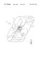
- FIG. 1is semi-diagrammatical perspective view of an embodiment of the camera. The positions of a film cassette and inlay transponder are indicated by dashed lines.
- FIG. 2is a diagrammatical view illustrating use of the transponder in the camera of FIG. 1 in an embodiment of the imaging system.
- FIG. 3is a semi-diagrammatical perspective view of the inlay transponder of FIG. 1 .
- FIG. 4is a semi-diagrammatical cross-sectional view of another embodiment of the camera. Some of the alternative locations for an inlay transponder are indicated by dashed lines.
- FIG. 5is a semi-diagrammatical perspective view of the camera of FIG. 1 modified by the addition of packaging.
- FIG. 6is a semi-diagrammatical perspective view of still another embodiment of the camera including the inlay transponder of FIG. 3 and a first embodiment of a film unit having an included inlay transponder.
- FIG. 7is a semi-diagrammatical perspective view of yet another embodiment of the camera including the inlay transponder of FIG. 3 and a second embodiment of a film unit having an included inlay transponder.
- FIG. 8is a semi-diagrammatical perspective view of the film unit of FIG. 6 .
- FIG. 9is a semi-diagrammatical perspective view of the film unit of FIG. 7, but following photofinishing including development of the filmstrip.
- the developed filmstripis illustrated partially extended to show the visible captured images.
- FIG. 10is a semi-diagrammatical perspective view of the film unit of FIG. 9 modified by the addition of packaging.
- FIG. 11is a partially cut-away, semi-diagrammatical perspective view of a third embodiment of the film unit.
- the location of the upper spool flangeis indicated by a dashed line.
- FIG. 12is a partially cut-away, semi-diagrammatical perspective view of a fourth embodiment of the film unit.
- the locations of the upper spool flange and inlay transponderare indicated by dashed lines.
- FIG. 13is a semi-diagrammatical perspective view of a fifth embodiment of the film unit.
- FIG. 14is a semi-diagrammatical perspective view of a sixth embodiment of the film unit.
- the locations of the upper spool flange and inlay transponderare indicated by dashed lines.
- FIG. 15is a semi-diagrammatical perspective view of a seventh embodiment of the film unit.
- FIG. 16is a diagrammatical view illustrating use of the transponder in the film unit of FIG. 9 in an embodiment of the imaging system.
- a camera 10has a body 12 having an image capture assembly 14 disposed in a casing 16 .
- a film unit or image capture unit 18is disposed in the body 12 in operative relation to the image capture assembly 14 .
- the camera 10is generally discussed herein in terms of a film unit 18 including photographic film, but it will be understood that the term “image capture unit 18 or film unit 18 ” is broadly defined and is inclusive of a camera 10 having a film unit 18 that stores information in digital form using electronic, or magnetic, or optical memory or the like.
- the body 12also holds a radio-frequency identification transponder 20 .
- the term “radio-frequency identification transponder”is used herein to refer to any of a class of compact radio receiver-transmitters which are powered by an ambient radio-frequency field (indicated by line pattern 22 in FIG. 2 ).
- the transponder 20is accessed by modulating the field 22 with an appropriate communication signal.
- the transponder 20reacts (indicated by arrow 24 in FIG. 2 ), responsive to the communication signal.
- the reactioncan be a responsive signal or a change in the transponder or both.
- the content of the communication signal and the response of the transponder 20are limited by the memory and control functions provided by the transponder and by the access time and bandwidth available for communication.
- the transpondercan be read and written in a manner similar to other digital memory devices used to store and retrieve digital information.
- multiple separately-accessible memory unitscan be provided. Access can be unlimited or can be limited by use of one or more access codes for the transponder as a whole, or different codes for each unit. Read and write functions can be provided together or access can be differentiated in some manner.
- the transponderis generally described herein as reacting to a communication signal by transmitting an encodement, earlier programmed in the transponder. It will be understood that such descriptions are not limiting of the possible scope of responses by the transponder.
- the encodement or encodements in the transponderare limited by practical considerations relating to constraints on the memory in the transponder, available bandwidth and access time. Within these constraints the encodement can vary. For example, the encodement can be uncompressed or compressed data or a pointer to remote data or some combination. Similarly, it will be understood that the communication signal may similarly vary in scope and content.
- the communication signal 22is generated and the encodement is detected by a communication unit or transceiver 26 .
- Suitable communication units 26are well known to those of skill in the art.
- the communication unit 26can be provided as part of a kiosk or other fixed structure or can be a handheld device.
- the communication unit 26is generally described herein as being provided as separate item external to and discrete from the camera body 12 .
- a communication unit 26can, however, be provided within a single body that also holds the transponder.
- the componentscan be configured as necessary to place the communication unit in operative relation with the transponder.
- a camera body 12can be enlarged as necessary to accommodate a communication unit 26 and a transponder can be positioned within the body 12 in operative relation to the communication unit 26 .
- a notable advantage of an internal communication unit 26is that the transponder can be accessed during use to record information related to individual captured images.
- the communication unit 26can access the transponder 20 without direct physical contact or very close proximity to the transponder.
- the transponder 20can thus be located in an area of the camera body 12 that precludes direct contact or close positioning. For cameras 10 having photographic film, this allows the transponder 20 to be positioned within a light-tight film enclosure 19 that holds the film. In this case, the transponder can still be accessed, even though the transponder is isolated from light-exposure along with the film.
- the transponder 20is retained in the camera 10 during use and does not degrade the usage of the image capture assembly 14 .
- the transponder 20 in the camera 10transmits an encodement signal 24 of camera related information responsive to a radio-frequency communication signal 22 from the communication unit 26 .
- Image information captured by the image capture assembly 14is sent by suitable transfer equipment to an imaging device 31 .
- the image informationis indicated by a small image of a film unit having the reference number 33 and the transfer equipment is indicated by an arrow 35 .
- the encodement or ancillary information derived from the encodement(indicated by arrow 37 ) is sent on a communication path 39 by the communication unit 26 , responsive to the encodement signal 24 , to the imaging device 31 .
- the imaging device 31then provides an output (not shown) responsive to the image information and the ancillary information.
- imaging deviceis used very broadly here to refer to any unit or units or system of equipment that process, modify, store, print, or display images and are capable of varying output on the basis of ancillary information received.
- Imaging deviceis inclusive of digital and conventional photofinishing equipment in all forms and includes developing equipment, scanners, viewers, and printers.
- the transfer equipmentvaries with the imaging device. For example, if the imaging device produces printed images from latent images captured on film, then the transfer equipment can be related to physical transport of the film having the latent images. On the other hand, if the imaging device produces digitally stored images from digital data recorded in a digital film unit, then the transfer equipment can be directed to the transport of signals bearing digital image information. This can be varied in a wide variety of ways. For example, digitial images can be transferred by shipping physical storage media. Photographic or other physical images can be digitized and transferred by use of electronics or other signal transmission equipment. Combinations of equipment can be used and the captured images can be changed in form, modified, edited, combined, or otherwise manipulated in any combination.
- the ancillary informationcan also vary widely.
- the ancillary informationcan be set-up parameters for a photofinishing device, a product selection or selection of product features, a modification of captured images in some manner, information for inclusion in or with a photofinishing product, or a request for or modification of optional services.
- the ancillary informationcan be the same encodement provided by the transponder. Limitations on memory in the transponder can alternatively be circumvented by use of small encodements that point to larger, separately stored units of information in local or remotely accessed look-up tables or databases or the like.
- an encodementcould include or point to a URL (universal resource locator) to provide access to an Internet site.
- URLuniversal resource locator
- a transponder 20can be written with an encodement containing or pointing to a remote memory unit containing owner information and photofinishing preferences. Images are then captured in the form of latent images on film within the camera. The camera and film are then brought to an communication unit 26 , that is part of is part of a kiosk or other film input station at which the film is submitted for processing. The transponder 20 is accessed by the communication unit, which then sends the respective ancillary information to an image device in the form of a photofinishing unit. The kiosk or other device can transmit the encodement digitally or by other means and modify photofinishing activities responsive to the information. The images are processed in accordance with the preferences and delivered in accordance with the owner information.
- the transponder 20is a unitary structure that includes any and all necessary antenna or antennas.
- the transponder 20can have any configuration, within the spatial constraints imposed by the camera 10 . It is preferred, however, that the transponder 20 is an inlay transponder 20 a .
- the term “inlay transponder 20 a ”is used herein to refer to a radio-frequency identification transponder that has a flexible support sheet 28 bearing a planar antenna 30 and integrated circuit chip 32 . Connectors 34 join the circuit chip 32 and antenna 30 and one or more insulation layers or coverings (not separately illustrated) are provided as necessary.
- the thickness of an inlay transponder 20 ais less than 20 times the smallest dimension of the circuit chip 32 and is, preferably, less than 10 times the smallest dimension of the circuit chip 32 and less than the largest dimension of the circuit chip 32 , and more preferably is less than 3 times the smallest dimension of the circuit chip 32 .
- the inlay transponder 20 acan be bent, in one or more directions, within limits imposed by the adherence of the circuit chip 32 , connectors, and antenna 30 to the support sheet 28 .
- the support sheet 28is electrically insulating plastic and the antenna 30 is a layer of conductive material deposited on the support sheet 28 .
- Inlay transponders 20 a of this typeare marketed by Texas Instruments Incorporated, of Dallas, Tex., as Tag-itTM Inlays.
- the antenna 30has, in its larger dimensions, has roughly the form of a rectangular helix 45 mm by 45 mm. The helix has 10 turns and a transverse dimension from inner turn to outer turn of about 11 mm. Connectors 34 and necessary insulation are also provided as deposited layers.
- the circuit chip 32is small, having larger dimensions of roughly 1 mm by 1 mm, and is bonded to the support sheet 28 in operative contact with the connectors 34 .
- the inlay transponder 20 acan be bent about a radius of 15 or 30 mm depending upon the orientation of the circuit chip 32 on the outside or inside of the curve, respectively.
- the image capture assembly 14includes conventional camera components, such as a taking lens unit 36 having one or more lens elements 38 , a shutter unit 40 , and a film transport (indicated in FIG. 4 by a rectangle 42 ).
- the image capture assembly 14can also include a flash assembly 44 including a lamp unit 46 and a circuit board 48 electrically connected to a flash tube (not shown) within the lamp unit 46 .
- the image capture assembly 14has control features 50 , such as a shutter release, flash charging button, counter, and viewfinder, positioned at the surface of the casing 16 for access by the user during picture taking.
- the image capture assembly 14can also include one or more other conventional camera components (symbolized by box 52 in FIG. 4 ), such as a timer, a control display, a date-back, and the like.
- the casing 16includes the structural elements of the camera 10 .
- the various parts of the image capture assembly 14are disposed within the casing 16 and can be firmly mounted to one or more members of the casing 16 or can be trapped in place by casing members.
- the casing 16has front and rear covers 54 , 56 and a frame 58 enclosed within the cover members 54 , 56 .
- the frame 58has first and second film chambers 60 , 62 , an exposure chamber 64 between the film chambers 60 , 62 , and a baffle 66 directing light from the taking lens unit 36 to the exposure chamber 64 .
- the cameras 10 illustratedare one-time use cameras.
- a filmstrip 68is prewound out of a holder 70 of the film unit 18 during manufacture to form a film roll 72 .
- the filmstrip 68is moved by the film transport 52 on a frame-by-frame basis through the exposure chamber 64 , for picture taking, and back into the holder 70 .
- the film unit 18 and film related mechanismsare not critical.
- the film unit 18can have a one chambered holder or patrone 70 , as in Type 135 (35 mm) and Advanced Photo System film units.
- the film unit 18can have a two chambered holder 70 , as in Type 110 film units.
- the film unit 18can have a holder 70 that is only a spool, as in Type 120 film units.
- the film unit 18can be prewound in the camera 10 or can require rewinding.
- the filmstrip 68can be moved from one spool to another during use or from a film roll to a spool or from film roll to film roll without any spools.
- the holder 70can include a canister and internal spool, as in the figures, or the holder can be a canister lacking a spool.
- the camera 10can have packaging 73 surrounding the body 12 , in the manner that packaging is commonly provided for products prior to sale to a final user.
- the packaging 73is removable and is removed to use the camera 10 .
- the packaging 73is waterproof to protect the filmstrip in the camera 10 from humidity.
- the manner of packagingcan vary widely.
- FIG. 5illustrates packaging 73 in the form of a waterproof plastic or foil laminate inner bag 73 a in combination with an outer non-waterproof hanger-box 73 b .
- the packaging 73can include a supernumerary transponder 74 as a security device or for inventory control or the like.
- the supernumerary transponder 74is independent of the transponder 20 in the camera body 12 , and is part of the packaging 73 rather than the camera body 12 .
- the transponder 20can be joined to the body 12 of the camera 10 . To protect against loss of information, it is highly preferred that the transponder 20 is inseparable from the body 12 without disassembly of the camera 10 or damage to the camera 10 .
- the transponder 20can be mounted to the casing 16 or the image capture assembly 14 and can be external or internal to the body 12 . Attachment of the transponder 20 to the body 12 can be provided by fasteners, but adherence using a layer of adhesive or solvent welding or the like is generally preferred.
- the transponder 20is positioned such it is unshielded by the body 12 .
- the body 12does not block transmission of appropriate radio frequency signals to and from the transponder 20 .
- the transponder 20be unshielded in all directions, however, shielding can limit signal transmission in one or more directions, if desired.
- the casing 16be made of plastic or other radio-frequency signal transmissive material.
- the transponder 20can be positioned in a variety of locations in the body 12 . This is particularly the case when the transponder 20 is an inlay transponder, since the inlay transponder is thin and can be bent. Some alternative locations for an inlay transponder 20 a are illustrated in dashed lines and reference designations beginning with “ 76 ”, in FIG. 4 .
- the inlay transponder 20 acan be mounted at 76 a (on the outside surface of the front cover 54 ), at 76 b (on the outside surface of the rear cover 56 ), at 76 c (on the inside surface of the front cover 54 ), or at 76 d (on the outside surfaces of front and rear covers 54 , 56 overlapping the joint between the two covers 54 , 56 ).
- the inlay transponder 20 acan be mounted at 76 e (in a recess in the inside of the rear cover 56 or a similar recess in another part).
- the inlay transponder 20 acan be mounted at 76 f (attached to an adhered label 78 ).
- the inlay transponder 20 ais preferably mounted internally within the body 12 of the camera 10 .
- the inlay transponder 20 aas noted above, can be mounted on an inside surface of a cover.
- the inlay transponder 20 acan also be attached to the frame 58 .
- the inlay transponder 20 acan be mounted to a flat surface or a curved surface and can bridge different parts of the camera 10 .
- the inlay transponder 20 acan be attached to one or more components of the image capture assembly 14 .
- FIG. 4illustrates a location, 76 k , for attachment of an inlay transponder 20 a to the circuit board 48 of the flash assembly 44 .
- the inlay transponder 20 acan be partially attached to a component or part, and partially free; or can be completely unattached, and simply trapped within the camera body 12 as shown at 76 m and 76 n , respectively.
- the camera 10can have a transponder 20 held by the film unit 18 in the camera body 12 .
- the transponder 20 in the film unit 18is unshielded by both the film unit 18 and the body 12 .
- An embodiment of the system 29shown in FIG. 16, is comparable to the system 29 previously described, except that the camera 10 is replaced by the film unit 18 .
- the film unit 18can also be returned to the user following processing, for example, by return of the developed filmstrip 68 a within the film canister 86 , as with Advanced Photo System film. In that case, the transponder can be retained to allow use of the transponder by the user and and/or in subsequent photofinishing.
- multiple transponderscan also be used as necessitated by multiple photofinishing products and information can be transferred from one transponder to another as needed.
- the film unit 18can be varied in accordance with the disclosure herein, as desired.
- the camera 10can also have a first transponder 20 ′ held by the film unit 18 and a second transponder 20 ′′ held by the body 12 independent of the film unit 18 .
- This approachhas the advantage that encodements related to captured image, such as image format can more easily be retained with the images and encodements related to the camera body 12 , such as the number of times a one-time use camera 10 has been recycled, can be retained with the recycled part of the camera body 12 .
- the two transponders 20 ′, 20 ′′can be used to store the same encodements or different encodements.
- the two transponders 20can be commonly accessible on the same radio frequencies, but are preferably independently accessible.
- the camera 10can also have a plurality of transponders 20 (not illustrated) separate from the film unit 18 , but, for current embodiments, this is superfluous and not preferred.
- a transponder 20 held by a film unit 18is an inlay transponder, since an inlay transponder is readily compatible with spatial constraints of a film unit 18 .
- An inlay transponder 20 acan be mounted to the film or to a holder 70 of the film unit 18 .
- the transponder 20can be adhered or otherwise attached or disposed in the film unit 18 in the same manner as previously described for the camera body 12 .
- the film unit 18is illustrated as a patrone in which the holder 70 is a canister including an internal spool and the filmstrip is attached to and wound around the spool, but the film unit 18 is not limited to any particular configuration.
- the film unit 18can have a single film chamber, as in a Type 135 (35 mm) or Advanced Photo SystemTM cassette, or the film unit 18 can have two film chambers, as in a Type 110 cassette, or the film unit 18 can have film wound on a bare spool, as in Type 120 and Type 220 films, or the film unit 18 can be an unspooled length of filmstrip.
- the holder 70can shield the transponder 20 from radio-frequency communication by the communication unit 26 , except in one or a limited number of directions or except in some conditions such as opening of an access door or outward extension of the transponder 20 . It is preferred, however, that the transponder 20 be continuously accessible and be accessible in any direction.
- the transponder 20can be mounted to the outer, light-blocking surface 80 of a film unit 18 , such as the exterior of a light-tight holder 70 , or can be mounted interior to that surface 80 within a film area 81 protected from incidental light exposure. In the latter case, the transponder is isolated from light-exposure in the same manner as the film. In either case, the transponder 20 can be accessed without direct contact or close positioning of the communication unit 26 . The transponder 20 can thus be accessed even when direct contact or close access to the film unit would be unsuitable, such as during use, when film is unwound from a light-tight holder 70 within a camera.
- the inlay transponder 20 ais mounted to a filmstrip end (leader or trailer) 82 .
- the inlay transponder 20 acan be cut from the filmstrip and handled separately during film finishing or can be subject to the same photofinishing processes as the remainder of the filmstrip. In the latter case, the filmstrip must have materials and a configuration that precludes unacceptable contamination of photofinishing solutions.
- the transponder 20can also be mounted to the holder 70 on an exterior or interior surface.
- FIG. 9illustrates an inlay transponder 20 a joined to the exterior surface of a sidewall 84 of a canister 86 .
- FIGS. 11 and 12illustrate inlay transponders 20 a joined to outer and inner surfaces, respectively, of the core 88 of a spool 90 .
- FIG. 15illustrates a transponder 20 joined to the exterior surface of an endwall 92 of a canister 86 .
- a transponder 20 mounted to the film or holder 70can be permanently affixed by adhesive or the like, or removable. The desirability of permanent or removable mounting depends upon the location of the transponder 20 and the photofinishing procedures to be used.
- a removable transponder 20has the advantage that it can be transferred during photofinishing from a discarded item, such as the canister of a Type 135 film unit, to a photofinishing product, such as an index print.
- a permanently mounted transponder 20is free from a risk of accidental removable, but requires retention of a supporting structure, such as an original filmstrip or canister.
- the film unit 18can have packaging 73 enwrapping the film and holder 70 , if any; in the manner that packaging is commonly provided for products prior to sale to a final user.
- the packaging 73is removable and is removed for use.
- the packaging 73is preferably waterproof to protect against humidity.
- the manner of packagingcan vary widely.
- FIG. 10illustrates packaging 73 in the form of a waterproof inner container 73 a in combination with an outer non-waterproof hanger-box 73 b .
- the packaging 73can include a supernumerary transponder 74 as a security device or for inventory control or the like.
- the supernumerary transponder 74is independent of the transponder 20 in the film unit 18 , and is part of the packaging 73 rather than the film unit 18 .
- the film unit 18can have more than one transponder 20 .
- two transponders 20can be used to store the same encodements for redundancy or as an aid in matching separated canisters 86 and respective filmstrips 68 during photofinishing.
- Multiple transponders 20can also be used to provide more storage capacity than would be possible with a single transponder 20 . In that case, each of the plurality of transponders 20 would store different encodements.
- the two transponders 20can be commonly accessible on the same radio frequencies, but are preferably independently accessible.
- the camera 10can also have one or more transponders 20 in the body 12 that are independent of the transponders 20 held by the film unit 18 .
Landscapes
- Engineering & Computer Science (AREA)
- Physics & Mathematics (AREA)
- General Physics & Mathematics (AREA)
- Computer Hardware Design (AREA)
- Microelectronics & Electronic Packaging (AREA)
- Theoretical Computer Science (AREA)
- Computer Networks & Wireless Communication (AREA)
- Mechanical Engineering (AREA)
- Studio Devices (AREA)
- Camera Bodies And Camera Details Or Accessories (AREA)
- Cameras In General (AREA)
- Structure And Mechanism Of Cameras (AREA)
Abstract
Description
Claims (21)
Priority Applications (5)
| Application Number | Priority Date | Filing Date | Title |
|---|---|---|---|
| US09/372,628US6173119B1 (en) | 1999-08-11 | 1999-08-11 | Camera having radio-frequency identification transponder |
| EP00202714AEP1076259B1 (en) | 1999-08-11 | 2000-07-31 | Camera having radio-frequency identification transponder |
| DE60031610TDE60031610T2 (en) | 1999-08-11 | 2000-07-31 | Camera with a high-frequency identification transponder |
| JP2000239470AJP2001109050A (en) | 1999-08-11 | 2000-08-08 | Camera, disposable camera and image system |
| US09/664,505US6811079B1 (en) | 1998-12-22 | 2000-09-18 | Sheet media package having radio-frequency identification transponder |
Applications Claiming Priority (1)
| Application Number | Priority Date | Filing Date | Title |
|---|---|---|---|
| US09/372,628US6173119B1 (en) | 1999-08-11 | 1999-08-11 | Camera having radio-frequency identification transponder |
Related Parent Applications (1)
| Application Number | Title | Priority Date | Filing Date |
|---|---|---|---|
| US09/372,287ContinuationUS6381416B2 (en) | 1998-12-22 | 1999-08-11 | Film unit having radio-frequency identification transponder |
Related Child Applications (1)
| Application Number | Title | Priority Date | Filing Date |
|---|---|---|---|
| US09/664,505ContinuationUS6811079B1 (en) | 1998-12-22 | 2000-09-18 | Sheet media package having radio-frequency identification transponder |
Publications (1)
| Publication Number | Publication Date |
|---|---|
| US6173119B1true US6173119B1 (en) | 2001-01-09 |
Family
ID=23468983
Family Applications (1)
| Application Number | Title | Priority Date | Filing Date |
|---|---|---|---|
| US09/372,628Expired - LifetimeUS6173119B1 (en) | 1998-12-22 | 1999-08-11 | Camera having radio-frequency identification transponder |
Country Status (4)
| Country | Link |
|---|---|
| US (1) | US6173119B1 (en) |
| EP (1) | EP1076259B1 (en) |
| JP (1) | JP2001109050A (en) |
| DE (1) | DE60031610T2 (en) |
Cited By (36)
| Publication number | Priority date | Publication date | Assignee | Title |
|---|---|---|---|---|
| US6381418B1 (en)* | 1999-08-11 | 2002-04-30 | Eastman Kodak Company | Print having information associated with the print stored in a memory coupled to the print |
| US6381416B2 (en)* | 1999-08-11 | 2002-04-30 | Eastman Kodak Company | Film unit having radio-frequency identification transponder |
| US20020176711A1 (en)* | 2001-05-23 | 2002-11-28 | Makoto Shizukuishi | Camera system |
| US20030063001A1 (en)* | 2001-10-01 | 2003-04-03 | Hohberger Clive P. | Method and apparatus for associating on demand certain selected media and value-adding elements |
| US20030137588A1 (en)* | 2002-01-23 | 2003-07-24 | Guan-Wu Wang | Wireless camera system |
| US6650831B1 (en)* | 1999-10-15 | 2003-11-18 | James Thompson | Method of providing access to photographic images over a computer network |
| US20030227528A1 (en)* | 2001-10-01 | 2003-12-11 | Zih Corp. | Printer or other media processor with on-demand selective media converter |
| US20030227550A1 (en)* | 2002-06-06 | 2003-12-11 | Manico Joseph A. | System and method for providing a customized imaging product or service |
| US6672508B2 (en)* | 2001-05-30 | 2004-01-06 | Eastman Kodak Company | Photographic processing system |
| US20040049733A1 (en)* | 2002-09-09 | 2004-03-11 | Eastman Kodak Company | Virtual annotation of a recording on an archival media |
| US20040062016A1 (en)* | 2002-09-27 | 2004-04-01 | Eastman Kodak Company | Medium having data storage and communication capabilites and method for forming same |
| US20040109682A1 (en)* | 2002-12-09 | 2004-06-10 | Eastman Kodak Company | Photographic processor and supply cartridge with an information exchange arrangement |
| US20040135892A1 (en)* | 2003-01-07 | 2004-07-15 | Masamine Maeda | Printing system |
| US6785739B1 (en) | 2000-02-23 | 2004-08-31 | Eastman Kodak Company | Data storage and retrieval playback apparatus for a still image receiver |
| US20040169587A1 (en)* | 2003-01-02 | 2004-09-02 | Washington Richard G. | Systems and methods for location of objects |
| US20040184801A1 (en)* | 2000-09-18 | 2004-09-23 | Vraa Timothy S. | Sheet media package having radio-frequency identification transponder |
| US6824320B1 (en)* | 2003-11-05 | 2004-11-30 | Eastman Kodak Company | Film core article and method for making same |
| US20050110613A1 (en)* | 2003-11-21 | 2005-05-26 | Kerr Roger S. | Media holder having communication capabilities |
| US20050134707A1 (en)* | 2003-12-18 | 2005-06-23 | Eastman Kodak Company | Image metadata attachment |
| US20050184985A1 (en)* | 2003-11-19 | 2005-08-25 | Kerr Roger S. | Illumination apparatus |
| US20050195292A1 (en)* | 2004-03-03 | 2005-09-08 | Eastman Kodak Company | System and method for providing a customized imaging product or service |
| US20050231583A1 (en)* | 2004-04-16 | 2005-10-20 | Zih Corp. | Systems and methods for providing a media located on a spool and/or a cartridge where the media includes a wireless communication device attached thereto |
| US20050244598A1 (en)* | 2002-07-25 | 2005-11-03 | Konica Minolta Photo Imaging, Inc. | Color photo film package |
| US20060002690A1 (en)* | 2004-07-01 | 2006-01-05 | Eastman Kodak Company | Intelligent media splice |
| US20060062096A1 (en)* | 2004-09-07 | 2006-03-23 | Eastman Kodak Company | System for updating a content bearing medium |
| US20060191022A1 (en)* | 2001-08-24 | 2006-08-24 | Zih Corp. | Method and apparatus for article authentication |
| US7145464B2 (en) | 2003-11-19 | 2006-12-05 | Eastman Kodak Company | Data collection device |
| US7233498B2 (en) | 2002-09-27 | 2007-06-19 | Eastman Kodak Company | Medium having data storage and communication capabilities and method for forming same |
| US20080012961A1 (en)* | 2006-07-14 | 2008-01-17 | Fuji Xerox Co., Ltd. | Image-forming apparatus, image-forming apparatus body, replacement part, and method of handling storage medium mounted on replacement part of image-forming apparatus |
| US20080112699A1 (en)* | 2006-11-13 | 2008-05-15 | Honeywell International Inc. | Method and system for automatically estimating the spatial positions of cameras in a camera network |
| US7406259B1 (en) | 2008-01-28 | 2008-07-29 | International Business Machines Corporation | Automatically powering on an electronic device such as a camcorder or camera by determining the real-time state of the enclosure for the device |
| US20110007078A1 (en)* | 2009-07-10 | 2011-01-13 | Microsoft Corporation | Creating Animations |
| USRE44220E1 (en) | 1998-06-18 | 2013-05-14 | Zih Corp. | Electronic identification system and method with source authenticity |
| US20140270745A1 (en)* | 2013-03-15 | 2014-09-18 | First Principles, Inc. | Continuous film and camera and method thereof |
| US8893977B2 (en) | 2010-04-08 | 2014-11-25 | Access Business Group International Llc | Point of sale inductive systems and methods |
| US10306123B2 (en)* | 2013-09-13 | 2019-05-28 | Lg Innotek Co., Ltd. | Camera module |
Families Citing this family (2)
| Publication number | Priority date | Publication date | Assignee | Title |
|---|---|---|---|---|
| AT413455B (en)* | 2002-01-18 | 2006-03-15 | Christian Ing Mag Tschida | SYSTEM WITH A CAMERA, PASSIVE ACCESSORY COMPONENT AND CONTROL DEVICE HIEFÜR |
| DE102020103838B4 (en) | 2020-02-13 | 2023-03-16 | Balluff Gmbh | goods surveillance system |
Citations (3)
| Publication number | Priority date | Publication date | Assignee | Title |
|---|---|---|---|---|
| US4806958A (en) | 1988-01-11 | 1989-02-21 | Eastman Kodak Company | Cassette/machine optically coupled interface |
| US5768633A (en)* | 1996-09-03 | 1998-06-16 | Eastman Kodak Company | Tradeshow photographic and data transmission system |
| US5995768A (en)* | 1996-01-19 | 1999-11-30 | Fuji Photo Film Co., Ltd. | Lens-fitted photo film unit and data recording method therefor |
Family Cites Families (10)
| Publication number | Priority date | Publication date | Assignee | Title |
|---|---|---|---|---|
| JPH03113387A (en)* | 1989-09-27 | 1991-05-14 | Nippon Soken Inc | Transponder for moving body identifying device |
| US5278606A (en)* | 1990-06-07 | 1994-01-11 | Canon Kabushiki Kaisha | Camera |
| AU670907B3 (en)* | 1995-11-03 | 1996-08-01 | Alfa Laval Agri Ab | Attachable transponder housing |
| JPH09211792A (en)* | 1996-02-06 | 1997-08-15 | Fuji Photo Film Co Ltd | Film cartridge with ic memory, data recording device and data input/output device therefor |
| FR2752982B1 (en)* | 1996-09-03 | 1998-11-27 | Mu 13 Ingenierie Sarl | METHOD AND DEVICE FOR REMOTE CONTROL OF ONE OR MORE CAMERAS |
| EP0833169A1 (en)* | 1996-09-19 | 1998-04-01 | Texas Instruments Incorporated | Improvements in or relating to radio-frequency identification systems |
| JP3625345B2 (en)* | 1996-12-06 | 2005-03-02 | キヤノン株式会社 | Image processing system |
| US6115137A (en)* | 1996-12-06 | 2000-09-05 | Canon Kabushiki Kaisha | Image processing system, digital camera, and printing apparatus |
| US5917542A (en)* | 1997-02-18 | 1999-06-29 | Eastman Kodak Company | System and method for digital image capture and transmission |
| DE19726938A1 (en)* | 1997-06-25 | 1999-01-07 | Bernhard Bruene | Cattle identification method |
- 1999
- 1999-08-11USUS09/372,628patent/US6173119B1/ennot_activeExpired - Lifetime
- 2000
- 2000-07-31EPEP00202714Apatent/EP1076259B1/ennot_activeExpired - Lifetime
- 2000-07-31DEDE60031610Tpatent/DE60031610T2/ennot_activeExpired - Lifetime
- 2000-08-08JPJP2000239470Apatent/JP2001109050A/enactivePending
Patent Citations (3)
| Publication number | Priority date | Publication date | Assignee | Title |
|---|---|---|---|---|
| US4806958A (en) | 1988-01-11 | 1989-02-21 | Eastman Kodak Company | Cassette/machine optically coupled interface |
| US5995768A (en)* | 1996-01-19 | 1999-11-30 | Fuji Photo Film Co., Ltd. | Lens-fitted photo film unit and data recording method therefor |
| US5768633A (en)* | 1996-09-03 | 1998-06-16 | Eastman Kodak Company | Tradeshow photographic and data transmission system |
Non-Patent Citations (11)
| Title |
|---|
| General Reference Manual, Texas Instruments Registration and Identification System, TIRIS Technology by Texas Instruments, "Description of Multipage, Selective Addressable & Selective Addressable (Secured) Transponders", Aug. 23, 1996. |
| Reference Manual, Texas Instruments Registration and Identification System, TIRIS Technology by Texas Instruments, "Micro-reader", Jul. 25, 1996. |
| Texas Instruments Product Bulletin, Tiris(TM) Radio Frequency Identification Solutions, "Tag-it(TM) Inlays", Jan. 1999. |
| Texas Instruments Product Bulletin, Tiris™ Radio Frequency Identification Solutions, "Tag-it™ Inlays", Jan. 1999. |
| Texas Instruments, "Making RFID work for you, An Industry Roundtable Hosted by Texas Instruments at NACS-Tech '98". |
| Texas Instruments, Tiris(TM) Radio Frequency Identification Solutions, "TIRIS Automatic Recognition of Consumers: Series 5000 Reader System", 1999. |
| Texas Instruments, Tiris(TM) Radio Frequency Identification Solutions, "Tiris for Automatic Recognition of Consumers". |
| Texas Instruments, Tiris™ Radio Frequency Identification Solutions, "TIRIS Automatic Recognition of Consumers: Series 5000 Reader System", 1999. |
| Texas Instruments, Tiris™ Radio Frequency Identification Solutions, "Tiris for Automatic Recognition of Consumers". |
| U.S. application Ser. No. 09/372,329 filed Aug. 11, 1999. |
| U.S. application Ser. No. 09/372,442 filed Aug. 11, 1999. |
Cited By (83)
| Publication number | Priority date | Publication date | Assignee | Title |
|---|---|---|---|---|
| USRE44220E1 (en) | 1998-06-18 | 2013-05-14 | Zih Corp. | Electronic identification system and method with source authenticity |
| US6381416B2 (en)* | 1999-08-11 | 2002-04-30 | Eastman Kodak Company | Film unit having radio-frequency identification transponder |
| US6381418B1 (en)* | 1999-08-11 | 2002-04-30 | Eastman Kodak Company | Print having information associated with the print stored in a memory coupled to the print |
| US6650831B1 (en)* | 1999-10-15 | 2003-11-18 | James Thompson | Method of providing access to photographic images over a computer network |
| US6785739B1 (en) | 2000-02-23 | 2004-08-31 | Eastman Kodak Company | Data storage and retrieval playback apparatus for a still image receiver |
| US6945713B2 (en) | 2000-09-18 | 2005-09-20 | Eastman Kodak Company | Sheet media package having radio-frequency identification transponder |
| US20040184801A1 (en)* | 2000-09-18 | 2004-09-23 | Vraa Timothy S. | Sheet media package having radio-frequency identification transponder |
| US20020176711A1 (en)* | 2001-05-23 | 2002-11-28 | Makoto Shizukuishi | Camera system |
| US7391967B2 (en)* | 2001-05-23 | 2008-06-24 | Fujifilm Corporation | Camera system |
| US6672508B2 (en)* | 2001-05-30 | 2004-01-06 | Eastman Kodak Company | Photographic processing system |
| US7664257B2 (en) | 2001-08-24 | 2010-02-16 | Zih Corp. | Method and apparatus for article authentication |
| US8667276B2 (en) | 2001-08-24 | 2014-03-04 | Zih Corp. | Method and apparatus for article authentication |
| US20100284531A1 (en)* | 2001-08-24 | 2010-11-11 | Zih Corp. | Method and apparatus for article authentication |
| US7137000B2 (en) | 2001-08-24 | 2006-11-14 | Zih Corp. | Method and apparatus for article authentication |
| US20060191022A1 (en)* | 2001-08-24 | 2006-08-24 | Zih Corp. | Method and apparatus for article authentication |
| EP2493111A1 (en) | 2001-08-24 | 2012-08-29 | ZIH Corp. | Method and apparatus for article authentication |
| EP2117157A1 (en) | 2001-08-24 | 2009-11-11 | ZIH Corporation | Method and apparatus for article authentication |
| US8301886B2 (en) | 2001-08-24 | 2012-10-30 | Zih Corp. | Method and apparatus for article authentication |
| US20030062131A1 (en)* | 2001-10-01 | 2003-04-03 | Hohberger Clive P. | Method and apparatus for associating on demand certain selected media and value-adding elements |
| US20030063001A1 (en)* | 2001-10-01 | 2003-04-03 | Hohberger Clive P. | Method and apparatus for associating on demand certain selected media and value-adding elements |
| US20030227528A1 (en)* | 2001-10-01 | 2003-12-11 | Zih Corp. | Printer or other media processor with on-demand selective media converter |
| US7112001B2 (en) | 2001-10-01 | 2006-09-26 | Zih Corp. | Method and apparatus for associating on demand certain selected media and value-adding elements |
| US20030062119A1 (en)* | 2001-10-01 | 2003-04-03 | Hohberger Clive P. | Method and apparatus for associating on demand certain selected media and value-adding elements |
| US20050002720A1 (en)* | 2001-10-01 | 2005-01-06 | Zih Corp. | Method and apparatus for associating on demand certain selected media and value-adding elements |
| US20050025553A1 (en)* | 2001-10-01 | 2005-02-03 | Zih Corp. | Method and apparatus for associating on demand certain selected media and value-adding elements |
| EP1444099A4 (en)* | 2001-10-01 | 2005-02-16 | Zih Corp | Method and apparatus for associating on demand certain selected media and value-adding elements |
| US6857714B2 (en) | 2001-10-01 | 2005-02-22 | Zih Corp. | Method and apparatus for associating on demand certain selected media and value-adding elements |
| US6969134B2 (en) | 2001-10-01 | 2005-11-29 | Zih Corp. | Printer or other media processor with on-demand selective media converter |
| WO2003029005A3 (en)* | 2001-10-01 | 2003-10-16 | Zih Corp | Method and apparatus for associating on demand certain selected media and value-adding elements |
| WO2003029005A2 (en) | 2001-10-01 | 2003-04-10 | Zih Corp. | Method and apparatus for associating on demand certain selected media and value-adding elements |
| US6942403B2 (en) | 2001-10-01 | 2005-09-13 | Zih Corp. | Method and apparatus for associating on demand certain selected media and value-adding elements |
| US7129986B2 (en) | 2002-01-23 | 2006-10-31 | Guan-Wu Wang | Wireless camera system |
| US20030137588A1 (en)* | 2002-01-23 | 2003-07-24 | Guan-Wu Wang | Wireless camera system |
| EP1369827A3 (en)* | 2002-06-06 | 2004-03-31 | Eastman Kodak Company | System and method for providing a customized imaging product or service |
| US20030227550A1 (en)* | 2002-06-06 | 2003-12-11 | Manico Joseph A. | System and method for providing a customized imaging product or service |
| US20050244598A1 (en)* | 2002-07-25 | 2005-11-03 | Konica Minolta Photo Imaging, Inc. | Color photo film package |
| US20040049733A1 (en)* | 2002-09-09 | 2004-03-11 | Eastman Kodak Company | Virtual annotation of a recording on an archival media |
| US20040062016A1 (en)* | 2002-09-27 | 2004-04-01 | Eastman Kodak Company | Medium having data storage and communication capabilites and method for forming same |
| US7233498B2 (en) | 2002-09-27 | 2007-06-19 | Eastman Kodak Company | Medium having data storage and communication capabilities and method for forming same |
| US20040109682A1 (en)* | 2002-12-09 | 2004-06-10 | Eastman Kodak Company | Photographic processor and supply cartridge with an information exchange arrangement |
| US6761491B2 (en) | 2002-12-09 | 2004-07-13 | Eastman Kodak Company | Photographic processor and supply cartridge with an information exchange arrangement |
| US7492262B2 (en) | 2003-01-02 | 2009-02-17 | Ge Security Inc. | Systems and methods for location of objects |
| US20040169587A1 (en)* | 2003-01-02 | 2004-09-02 | Washington Richard G. | Systems and methods for location of objects |
| US7151454B2 (en) | 2003-01-02 | 2006-12-19 | Covi Technologies | Systems and methods for location of objects |
| US8233043B2 (en) | 2003-01-02 | 2012-07-31 | Utc Fire & Security Americas Corporation, Inc. | Systems and methods for location of objects |
| US20070097211A1 (en)* | 2003-01-02 | 2007-05-03 | Covi Technologies, Inc. | Systems and methods for location of objects |
| US20070103313A1 (en)* | 2003-01-02 | 2007-05-10 | Covi Technologies, Inc. | Systems and methods for location of objects |
| US7443420B2 (en)* | 2003-01-07 | 2008-10-28 | Canon Kabushiki Kaisha | Printing system including a printing apparatus for printing image data transmitted from an image pickup apparatus identified by an approved ID information |
| US20040135892A1 (en)* | 2003-01-07 | 2004-07-15 | Masamine Maeda | Printing system |
| US6824320B1 (en)* | 2003-11-05 | 2004-11-30 | Eastman Kodak Company | Film core article and method for making same |
| US7145464B2 (en) | 2003-11-19 | 2006-12-05 | Eastman Kodak Company | Data collection device |
| US7109986B2 (en) | 2003-11-19 | 2006-09-19 | Eastman Kodak Company | Illumination apparatus |
| US20050184985A1 (en)* | 2003-11-19 | 2005-08-25 | Kerr Roger S. | Illumination apparatus |
| US7009494B2 (en) | 2003-11-21 | 2006-03-07 | Eastman Kodak Company | Media holder having communication capabilities |
| US20050110613A1 (en)* | 2003-11-21 | 2005-05-26 | Kerr Roger S. | Media holder having communication capabilities |
| US20050134707A1 (en)* | 2003-12-18 | 2005-06-23 | Eastman Kodak Company | Image metadata attachment |
| US20090195663A1 (en)* | 2003-12-18 | 2009-08-06 | Perotti Jennifer C | Image metadata attachment |
| US7528868B2 (en) | 2003-12-18 | 2009-05-05 | Eastman Kodak Company | Image metadata attachment |
| US7724290B2 (en) | 2003-12-18 | 2010-05-25 | Eastman Kodak Company | Image metadata attachment |
| US20050195292A1 (en)* | 2004-03-03 | 2005-09-08 | Eastman Kodak Company | System and method for providing a customized imaging product or service |
| US20070286660A1 (en)* | 2004-04-16 | 2007-12-13 | Zih Corp. | Systems and Methods for Providing a Media Located on a Spool and/or a Cartridge Where the Media Includes a Wireless Communication Device Attached Thereto |
| US20050231583A1 (en)* | 2004-04-16 | 2005-10-20 | Zih Corp. | Systems and methods for providing a media located on a spool and/or a cartridge where the media includes a wireless communication device attached thereto |
| US7206010B2 (en) | 2004-04-16 | 2007-04-17 | Zih Corp. | Systems and methods for providing a media located on a spool and/or a cartridge where the media includes a wireless communication device attached thereto |
| US20060002690A1 (en)* | 2004-07-01 | 2006-01-05 | Eastman Kodak Company | Intelligent media splice |
| US8035482B2 (en) | 2004-09-07 | 2011-10-11 | Eastman Kodak Company | System for updating a content bearing medium |
| US20060062096A1 (en)* | 2004-09-07 | 2006-03-23 | Eastman Kodak Company | System for updating a content bearing medium |
| US20080012961A1 (en)* | 2006-07-14 | 2008-01-17 | Fuji Xerox Co., Ltd. | Image-forming apparatus, image-forming apparatus body, replacement part, and method of handling storage medium mounted on replacement part of image-forming apparatus |
| US7801460B2 (en)* | 2006-07-14 | 2010-09-21 | Fuji Xerox Co., Ltd. | Image-forming apparatus, image-forming apparatus body, replacement part, and method of handling storage medium mounted on replacement part of image-forming apparatus |
| US20080112699A1 (en)* | 2006-11-13 | 2008-05-15 | Honeywell International Inc. | Method and system for automatically estimating the spatial positions of cameras in a camera network |
| US7756415B2 (en)* | 2006-11-13 | 2010-07-13 | Honeywell International Inc. | Method and system for automatically estimating the spatial positions of cameras in a camera network |
| US7532246B1 (en) | 2008-01-28 | 2009-05-12 | International Business Machines Corporation | Automatically powering on an electronic device such as a camcorder or camera by determining the real-time state of the enclosure for the device |
| US7406259B1 (en) | 2008-01-28 | 2008-07-29 | International Business Machines Corporation | Automatically powering on an electronic device such as a camcorder or camera by determining the real-time state of the enclosure for the device |
| US8325192B2 (en)* | 2009-07-10 | 2012-12-04 | Microsoft Corporation | Creating animations |
| US20110007078A1 (en)* | 2009-07-10 | 2011-01-13 | Microsoft Corporation | Creating Animations |
| US8633934B2 (en)* | 2009-07-10 | 2014-01-21 | Microsoft Corporation | Creating animations |
| US8893977B2 (en) | 2010-04-08 | 2014-11-25 | Access Business Group International Llc | Point of sale inductive systems and methods |
| US9027840B2 (en) | 2010-04-08 | 2015-05-12 | Access Business Group International Llc | Point of sale inductive systems and methods |
| US9424446B2 (en) | 2010-04-08 | 2016-08-23 | Access Business Group International Llc | Point of sale inductive systems and methods |
| US20140270745A1 (en)* | 2013-03-15 | 2014-09-18 | First Principles, Inc. | Continuous film and camera and method thereof |
| US9039306B2 (en)* | 2013-03-15 | 2015-05-26 | First Principles, Inc. | Continuous film and camera and method thereof |
| US9288341B2 (en)* | 2013-03-15 | 2016-03-15 | First Principles, Inc. | Continuous film and camera and method thereof |
| US9288340B2 (en)* | 2013-03-15 | 2016-03-15 | First Principles, Inc. | Continuous film and camera and method thereof |
| US10306123B2 (en)* | 2013-09-13 | 2019-05-28 | Lg Innotek Co., Ltd. | Camera module |
Also Published As
| Publication number | Publication date |
|---|---|
| DE60031610D1 (en) | 2006-12-14 |
| EP1076259A1 (en) | 2001-02-14 |
| EP1076259B1 (en) | 2006-11-02 |
| DE60031610T2 (en) | 2007-08-23 |
| JP2001109050A (en) | 2001-04-20 |
Similar Documents
| Publication | Publication Date | Title |
|---|---|---|
| US6173119B1 (en) | Camera having radio-frequency identification transponder | |
| US6381416B2 (en) | Film unit having radio-frequency identification transponder | |
| US5995768A (en) | Lens-fitted photo film unit and data recording method therefor | |
| US6710891B1 (en) | Sheet media system having radio-frequency identification transponder | |
| EP1079268B1 (en) | A print having attached audio data storage and method of providing same | |
| US5488445A (en) | Lens-fitted photographic film package and production method therefor | |
| US5083155A (en) | Cartridge for developed photographic film | |
| US6945713B2 (en) | Sheet media package having radio-frequency identification transponder | |
| JP2001143026A (en) | Print storing information concerning printing, in memory connected to the print | |
| US6078756A (en) | Photographic and data transmission system for capturing images and magnetic data | |
| US7391967B2 (en) | Camera system | |
| US6824320B1 (en) | Film core article and method for making same | |
| US6811079B1 (en) | Sheet media package having radio-frequency identification transponder | |
| EP1081540B1 (en) | A multistage system for processing photographic film | |
| JPH02118567A (en) | Film cartridge | |
| JPH0823671B2 (en) | Patrone with information | |
| JPH02118555A (en) | Dummy format camera system | |
| JPH11249254A (en) | Film with ic memory and equipment using this film | |
| JPH09203956A (en) | Camera with data recording function | |
| JPH11119329A (en) | Film back and camera | |
| JPH11102048A (en) | Film with lens and information control device | |
| JPH03263036A (en) | Film-housing container and method for checking used state of film | |
| JP2002023319A (en) | Method for manufacturing photographic film cartridge | |
| JPH08183283A (en) | Photograph storage case and photograph album | |
| JPH09211793A (en) | Method for attaching memory module to photographic film cartridge |
Legal Events
| Date | Code | Title | Description |
|---|---|---|---|
| AS | Assignment | Owner name:EASTMAN KODAK COMPANY, NEW YORK Free format text:ASSIGNMENT OF ASSIGNORS INTEREST;ASSIGNORS:MANICO, JOSEPH A.;SPURR, ROBERT W.;REEL/FRAME:010168/0146 Effective date:19990811 | |
| STCF | Information on status: patent grant | Free format text:PATENTED CASE | |
| FEPP | Fee payment procedure | Free format text:PAYOR NUMBER ASSIGNED (ORIGINAL EVENT CODE: ASPN); ENTITY STATUS OF PATENT OWNER: LARGE ENTITY | |
| FPAY | Fee payment | Year of fee payment:4 | |
| FPAY | Fee payment | Year of fee payment:8 | |
| AS | Assignment | Owner name:CITICORP NORTH AMERICA, INC., AS AGENT, NEW YORK Free format text:SECURITY INTEREST;ASSIGNORS:EASTMAN KODAK COMPANY;PAKON, INC.;REEL/FRAME:028201/0420 Effective date:20120215 | |
| FPAY | Fee payment | Year of fee payment:12 | |
| AS | Assignment | Owner name:EASTMAN KODAK COMPANY, NEW YORK Free format text:PATENT RELEASE;ASSIGNORS:CITICORP NORTH AMERICA, INC.;WILMINGTON TRUST, NATIONAL ASSOCIATION;REEL/FRAME:029913/0001 Effective date:20130201 Owner name:KODAK PORTUGUESA LIMITED, NEW YORK Free format text:PATENT RELEASE;ASSIGNORS:CITICORP NORTH AMERICA, INC.;WILMINGTON TRUST, NATIONAL ASSOCIATION;REEL/FRAME:029913/0001 Effective date:20130201 Owner name:KODAK (NEAR EAST), INC., NEW YORK Free format text:PATENT RELEASE;ASSIGNORS:CITICORP NORTH AMERICA, INC.;WILMINGTON TRUST, NATIONAL ASSOCIATION;REEL/FRAME:029913/0001 Effective date:20130201 Owner name:KODAK PHILIPPINES, LTD., NEW YORK Free format text:PATENT RELEASE;ASSIGNORS:CITICORP NORTH AMERICA, INC.;WILMINGTON TRUST, NATIONAL ASSOCIATION;REEL/FRAME:029913/0001 Effective date:20130201 Owner name:PAKON, INC., INDIANA Free format text:PATENT RELEASE;ASSIGNORS:CITICORP NORTH AMERICA, INC.;WILMINGTON TRUST, NATIONAL ASSOCIATION;REEL/FRAME:029913/0001 Effective date:20130201 Owner name:FAR EAST DEVELOPMENT LTD., NEW YORK Free format text:PATENT RELEASE;ASSIGNORS:CITICORP NORTH AMERICA, INC.;WILMINGTON TRUST, NATIONAL ASSOCIATION;REEL/FRAME:029913/0001 Effective date:20130201 Owner name:QUALEX INC., NORTH CAROLINA Free format text:PATENT RELEASE;ASSIGNORS:CITICORP NORTH AMERICA, INC.;WILMINGTON TRUST, NATIONAL ASSOCIATION;REEL/FRAME:029913/0001 Effective date:20130201 Owner name:KODAK REALTY, INC., NEW YORK Free format text:PATENT RELEASE;ASSIGNORS:CITICORP NORTH AMERICA, INC.;WILMINGTON TRUST, NATIONAL ASSOCIATION;REEL/FRAME:029913/0001 Effective date:20130201 Owner name:KODAK AMERICAS, LTD., NEW YORK Free format text:PATENT RELEASE;ASSIGNORS:CITICORP NORTH AMERICA, INC.;WILMINGTON TRUST, NATIONAL ASSOCIATION;REEL/FRAME:029913/0001 Effective date:20130201 Owner name:KODAK IMAGING NETWORK, INC., CALIFORNIA Free format text:PATENT RELEASE;ASSIGNORS:CITICORP NORTH AMERICA, INC.;WILMINGTON TRUST, NATIONAL ASSOCIATION;REEL/FRAME:029913/0001 Effective date:20130201 Owner name:KODAK AVIATION LEASING LLC, NEW YORK Free format text:PATENT RELEASE;ASSIGNORS:CITICORP NORTH AMERICA, INC.;WILMINGTON TRUST, NATIONAL ASSOCIATION;REEL/FRAME:029913/0001 Effective date:20130201 Owner name:NPEC INC., NEW YORK Free format text:PATENT RELEASE;ASSIGNORS:CITICORP NORTH AMERICA, INC.;WILMINGTON TRUST, NATIONAL ASSOCIATION;REEL/FRAME:029913/0001 Effective date:20130201 Owner name:FPC INC., CALIFORNIA Free format text:PATENT RELEASE;ASSIGNORS:CITICORP NORTH AMERICA, INC.;WILMINGTON TRUST, NATIONAL ASSOCIATION;REEL/FRAME:029913/0001 Effective date:20130201 Owner name:CREO MANUFACTURING AMERICA LLC, WYOMING Free format text:PATENT RELEASE;ASSIGNORS:CITICORP NORTH AMERICA, INC.;WILMINGTON TRUST, NATIONAL ASSOCIATION;REEL/FRAME:029913/0001 Effective date:20130201 Owner name:LASER-PACIFIC MEDIA CORPORATION, NEW YORK Free format text:PATENT RELEASE;ASSIGNORS:CITICORP NORTH AMERICA, INC.;WILMINGTON TRUST, NATIONAL ASSOCIATION;REEL/FRAME:029913/0001 Effective date:20130201 Owner name:EASTMAN KODAK INTERNATIONAL CAPITAL COMPANY, INC., Free format text:PATENT RELEASE;ASSIGNORS:CITICORP NORTH AMERICA, INC.;WILMINGTON TRUST, NATIONAL ASSOCIATION;REEL/FRAME:029913/0001 Effective date:20130201 | |
| AS | Assignment | Owner name:INTELLECTUAL VENTURES FUND 83 LLC, NEVADA Free format text:ASSIGNMENT OF ASSIGNORS INTEREST;ASSIGNOR:EASTMAN KODAK COMPANY;REEL/FRAME:030269/0001 Effective date:20130201 | |
| AS | Assignment | Owner name:MONUMENT PEAK VENTURES, LLC, TEXAS Free format text:ASSIGNMENT OF ASSIGNORS INTEREST;ASSIGNOR:INTELLECTUAL VENTURES FUND 83 LLC;REEL/FRAME:041941/0079 Effective date:20170215 | |
| AS | Assignment | Owner name:MONUMENT PEAK VENTURES, LLC, TEXAS Free format text:RELEASE BY SECURED PARTY;ASSIGNOR:INTELLECTUAL VENTURES FUND 83 LLC;REEL/FRAME:064599/0304 Effective date:20230728 |