US6172616B1 - Wide area communications network for remote data generating stations - Google Patents
Wide area communications network for remote data generating stationsDownload PDFInfo
- Publication number
- US6172616B1 US6172616B1US09/296,359US29635999AUS6172616B1US 6172616 B1US6172616 B1US 6172616B1US 29635999 AUS29635999 AUS 29635999AUS 6172616 B1US6172616 B1US 6172616B1
- Authority
- US
- United States
- Prior art keywords
- telemetry
- measurements
- devices
- parameter
- series
- Prior art date
- Legal status (The legal status is an assumption and is not a legal conclusion. Google has not performed a legal analysis and makes no representation as to the accuracy of the status listed.)
- Expired - Lifetime
Links
Images

Classifications
- H—ELECTRICITY
- H04—ELECTRIC COMMUNICATION TECHNIQUE
- H04Q—SELECTING
- H04Q9/00—Arrangements in telecontrol or telemetry systems for selectively calling a substation from a main station, in which substation desired apparatus is selected for applying a control signal thereto or for obtaining measured values therefrom
- H04Q9/14—Calling by using pulses
- G—PHYSICS
- G01—MEASURING; TESTING
- G01D—MEASURING NOT SPECIALLY ADAPTED FOR A SPECIFIC VARIABLE; ARRANGEMENTS FOR MEASURING TWO OR MORE VARIABLES NOT COVERED IN A SINGLE OTHER SUBCLASS; TARIFF METERING APPARATUS; MEASURING OR TESTING NOT OTHERWISE PROVIDED FOR
- G01D4/00—Tariff metering apparatus
- G01D4/002—Remote reading of utility meters
- G01D4/004—Remote reading of utility meters to a fixed location
- G—PHYSICS
- G01—MEASURING; TESTING
- G01D—MEASURING NOT SPECIALLY ADAPTED FOR A SPECIFIC VARIABLE; ARRANGEMENTS FOR MEASURING TWO OR MORE VARIABLES NOT COVERED IN A SINGLE OTHER SUBCLASS; TARIFF METERING APPARATUS; MEASURING OR TESTING NOT OTHERWISE PROVIDED FOR
- G01D4/00—Tariff metering apparatus
- G01D4/008—Modifications to installed utility meters to enable remote reading
- G—PHYSICS
- G08—SIGNALLING
- G08C—TRANSMISSION SYSTEMS FOR MEASURED VALUES, CONTROL OR SIMILAR SIGNALS
- G08C15/00—Arrangements characterised by the use of multiplexing for the transmission of a plurality of signals over a common path
- G—PHYSICS
- G08—SIGNALLING
- G08C—TRANSMISSION SYSTEMS FOR MEASURED VALUES, CONTROL OR SIMILAR SIGNALS
- G08C15/00—Arrangements characterised by the use of multiplexing for the transmission of a plurality of signals over a common path
- G08C15/06—Arrangements characterised by the use of multiplexing for the transmission of a plurality of signals over a common path successively, i.e. using time division
- H—ELECTRICITY
- H02—GENERATION; CONVERSION OR DISTRIBUTION OF ELECTRIC POWER
- H02J—CIRCUIT ARRANGEMENTS OR SYSTEMS FOR SUPPLYING OR DISTRIBUTING ELECTRIC POWER; SYSTEMS FOR STORING ELECTRIC ENERGY
- H02J13/00—Circuit arrangements for providing remote indication of network conditions, e.g. an instantaneous record of the open or closed condition of each circuitbreaker in the network; Circuit arrangements for providing remote control of switching means in a power distribution network, e.g. switching in and out of current consumers by using a pulse code signal carried by the network
- H02J13/00006—Circuit arrangements for providing remote indication of network conditions, e.g. an instantaneous record of the open or closed condition of each circuitbreaker in the network; Circuit arrangements for providing remote control of switching means in a power distribution network, e.g. switching in and out of current consumers by using a pulse code signal carried by the network characterised by information or instructions transport means between the monitoring, controlling or managing units and monitored, controlled or operated power network element or electrical equipment
- H02J13/00016—Circuit arrangements for providing remote indication of network conditions, e.g. an instantaneous record of the open or closed condition of each circuitbreaker in the network; Circuit arrangements for providing remote control of switching means in a power distribution network, e.g. switching in and out of current consumers by using a pulse code signal carried by the network characterised by information or instructions transport means between the monitoring, controlling or managing units and monitored, controlled or operated power network element or electrical equipment using a wired telecommunication network or a data transmission bus
- H02J13/00017—Circuit arrangements for providing remote indication of network conditions, e.g. an instantaneous record of the open or closed condition of each circuitbreaker in the network; Circuit arrangements for providing remote control of switching means in a power distribution network, e.g. switching in and out of current consumers by using a pulse code signal carried by the network characterised by information or instructions transport means between the monitoring, controlling or managing units and monitored, controlled or operated power network element or electrical equipment using a wired telecommunication network or a data transmission bus using optical fiber
- H—ELECTRICITY
- H02—GENERATION; CONVERSION OR DISTRIBUTION OF ELECTRIC POWER
- H02J—CIRCUIT ARRANGEMENTS OR SYSTEMS FOR SUPPLYING OR DISTRIBUTING ELECTRIC POWER; SYSTEMS FOR STORING ELECTRIC ENERGY
- H02J13/00—Circuit arrangements for providing remote indication of network conditions, e.g. an instantaneous record of the open or closed condition of each circuitbreaker in the network; Circuit arrangements for providing remote control of switching means in a power distribution network, e.g. switching in and out of current consumers by using a pulse code signal carried by the network
- H02J13/00006—Circuit arrangements for providing remote indication of network conditions, e.g. an instantaneous record of the open or closed condition of each circuitbreaker in the network; Circuit arrangements for providing remote control of switching means in a power distribution network, e.g. switching in and out of current consumers by using a pulse code signal carried by the network characterised by information or instructions transport means between the monitoring, controlling or managing units and monitored, controlled or operated power network element or electrical equipment
- H02J13/00028—Circuit arrangements for providing remote indication of network conditions, e.g. an instantaneous record of the open or closed condition of each circuitbreaker in the network; Circuit arrangements for providing remote control of switching means in a power distribution network, e.g. switching in and out of current consumers by using a pulse code signal carried by the network characterised by information or instructions transport means between the monitoring, controlling or managing units and monitored, controlled or operated power network element or electrical equipment involving the use of Internet protocols
- H—ELECTRICITY
- H02—GENERATION; CONVERSION OR DISTRIBUTION OF ELECTRIC POWER
- H02J—CIRCUIT ARRANGEMENTS OR SYSTEMS FOR SUPPLYING OR DISTRIBUTING ELECTRIC POWER; SYSTEMS FOR STORING ELECTRIC ENERGY
- H02J13/00—Circuit arrangements for providing remote indication of network conditions, e.g. an instantaneous record of the open or closed condition of each circuitbreaker in the network; Circuit arrangements for providing remote control of switching means in a power distribution network, e.g. switching in and out of current consumers by using a pulse code signal carried by the network
- H02J13/00032—Systems characterised by the controlled or operated power network elements or equipment, the power network elements or equipment not otherwise provided for
- H02J13/00034—Systems characterised by the controlled or operated power network elements or equipment, the power network elements or equipment not otherwise provided for the elements or equipment being or involving an electric power substation
- H—ELECTRICITY
- H04—ELECTRIC COMMUNICATION TECHNIQUE
- H04L—TRANSMISSION OF DIGITAL INFORMATION, e.g. TELEGRAPHIC COMMUNICATION
- H04L12/00—Data switching networks
- H04L12/28—Data switching networks characterised by path configuration, e.g. LAN [Local Area Networks] or WAN [Wide Area Networks]
- H04L12/2854—Wide area networks, e.g. public data networks
- H—ELECTRICITY
- H04—ELECTRIC COMMUNICATION TECHNIQUE
- H04L—TRANSMISSION OF DIGITAL INFORMATION, e.g. TELEGRAPHIC COMMUNICATION
- H04L43/00—Arrangements for monitoring or testing data switching networks
- H04L43/08—Monitoring or testing based on specific metrics, e.g. QoS, energy consumption or environmental parameters
- H04L43/0805—Monitoring or testing based on specific metrics, e.g. QoS, energy consumption or environmental parameters by checking availability
- H04L43/0817—Monitoring or testing based on specific metrics, e.g. QoS, energy consumption or environmental parameters by checking availability by checking functioning
- H—ELECTRICITY
- H04—ELECTRIC COMMUNICATION TECHNIQUE
- H04W—WIRELESS COMMUNICATION NETWORKS
- H04W74/00—Wireless channel access
- H04W74/08—Non-scheduled access, e.g. ALOHA
- H—ELECTRICITY
- H04—ELECTRIC COMMUNICATION TECHNIQUE
- H04L—TRANSMISSION OF DIGITAL INFORMATION, e.g. TELEGRAPHIC COMMUNICATION
- H04L43/00—Arrangements for monitoring or testing data switching networks
- H04L43/02—Capturing of monitoring data
- H04L43/022—Capturing of monitoring data by sampling
- H—ELECTRICITY
- H04—ELECTRIC COMMUNICATION TECHNIQUE
- H04L—TRANSMISSION OF DIGITAL INFORMATION, e.g. TELEGRAPHIC COMMUNICATION
- H04L43/00—Arrangements for monitoring or testing data switching networks
- H04L43/08—Monitoring or testing based on specific metrics, e.g. QoS, energy consumption or environmental parameters
- H04L43/0823—Errors, e.g. transmission errors
- H04L43/0829—Packet loss
- H—ELECTRICITY
- H04—ELECTRIC COMMUNICATION TECHNIQUE
- H04W—WIRELESS COMMUNICATION NETWORKS
- H04W24/00—Supervisory, monitoring or testing arrangements
- H04W24/10—Scheduling measurement reports ; Arrangements for measurement reports
- H—ELECTRICITY
- H04—ELECTRIC COMMUNICATION TECHNIQUE
- H04W—WIRELESS COMMUNICATION NETWORKS
- H04W74/00—Wireless channel access
- H04W74/04—Scheduled access
- H04W74/06—Scheduled access using polling
- H—ELECTRICITY
- H04—ELECTRIC COMMUNICATION TECHNIQUE
- H04W—WIRELESS COMMUNICATION NETWORKS
- H04W8/00—Network data management
- H04W8/26—Network addressing or numbering for mobility support
- H—ELECTRICITY
- H04—ELECTRIC COMMUNICATION TECHNIQUE
- H04W—WIRELESS COMMUNICATION NETWORKS
- H04W84/00—Network topologies
- H04W84/02—Hierarchically pre-organised networks, e.g. paging networks, cellular networks, WLAN [Wireless Local Area Network] or WLL [Wireless Local Loop]
- H04W84/04—Large scale networks; Deep hierarchical networks
- Y—GENERAL TAGGING OF NEW TECHNOLOGICAL DEVELOPMENTS; GENERAL TAGGING OF CROSS-SECTIONAL TECHNOLOGIES SPANNING OVER SEVERAL SECTIONS OF THE IPC; TECHNICAL SUBJECTS COVERED BY FORMER USPC CROSS-REFERENCE ART COLLECTIONS [XRACs] AND DIGESTS
- Y02—TECHNOLOGIES OR APPLICATIONS FOR MITIGATION OR ADAPTATION AGAINST CLIMATE CHANGE
- Y02B—CLIMATE CHANGE MITIGATION TECHNOLOGIES RELATED TO BUILDINGS, e.g. HOUSING, HOUSE APPLIANCES OR RELATED END-USER APPLICATIONS
- Y02B70/00—Technologies for an efficient end-user side electric power management and consumption
- Y02B70/30—Systems integrating technologies related to power network operation and communication or information technologies for improving the carbon footprint of the management of residential or tertiary loads, i.e. smart grids as climate change mitigation technology in the buildings sector, including also the last stages of power distribution and the control, monitoring or operating management systems at local level
- Y—GENERAL TAGGING OF NEW TECHNOLOGICAL DEVELOPMENTS; GENERAL TAGGING OF CROSS-SECTIONAL TECHNOLOGIES SPANNING OVER SEVERAL SECTIONS OF THE IPC; TECHNICAL SUBJECTS COVERED BY FORMER USPC CROSS-REFERENCE ART COLLECTIONS [XRACs] AND DIGESTS
- Y02—TECHNOLOGIES OR APPLICATIONS FOR MITIGATION OR ADAPTATION AGAINST CLIMATE CHANGE
- Y02B—CLIMATE CHANGE MITIGATION TECHNOLOGIES RELATED TO BUILDINGS, e.g. HOUSING, HOUSE APPLIANCES OR RELATED END-USER APPLICATIONS
- Y02B90/00—Enabling technologies or technologies with a potential or indirect contribution to GHG emissions mitigation
- Y02B90/20—Smart grids as enabling technology in buildings sector
- Y—GENERAL TAGGING OF NEW TECHNOLOGICAL DEVELOPMENTS; GENERAL TAGGING OF CROSS-SECTIONAL TECHNOLOGIES SPANNING OVER SEVERAL SECTIONS OF THE IPC; TECHNICAL SUBJECTS COVERED BY FORMER USPC CROSS-REFERENCE ART COLLECTIONS [XRACs] AND DIGESTS
- Y04—INFORMATION OR COMMUNICATION TECHNOLOGIES HAVING AN IMPACT ON OTHER TECHNOLOGY AREAS
- Y04S—SYSTEMS INTEGRATING TECHNOLOGIES RELATED TO POWER NETWORK OPERATION, COMMUNICATION OR INFORMATION TECHNOLOGIES FOR IMPROVING THE ELECTRICAL POWER GENERATION, TRANSMISSION, DISTRIBUTION, MANAGEMENT OR USAGE, i.e. SMART GRIDS
- Y04S20/00—Management or operation of end-user stationary applications or the last stages of power distribution; Controlling, monitoring or operating thereof
- Y04S20/20—End-user application control systems
- Y—GENERAL TAGGING OF NEW TECHNOLOGICAL DEVELOPMENTS; GENERAL TAGGING OF CROSS-SECTIONAL TECHNOLOGIES SPANNING OVER SEVERAL SECTIONS OF THE IPC; TECHNICAL SUBJECTS COVERED BY FORMER USPC CROSS-REFERENCE ART COLLECTIONS [XRACs] AND DIGESTS
- Y04—INFORMATION OR COMMUNICATION TECHNOLOGIES HAVING AN IMPACT ON OTHER TECHNOLOGY AREAS
- Y04S—SYSTEMS INTEGRATING TECHNOLOGIES RELATED TO POWER NETWORK OPERATION, COMMUNICATION OR INFORMATION TECHNOLOGIES FOR IMPROVING THE ELECTRICAL POWER GENERATION, TRANSMISSION, DISTRIBUTION, MANAGEMENT OR USAGE, i.e. SMART GRIDS
- Y04S20/00—Management or operation of end-user stationary applications or the last stages of power distribution; Controlling, monitoring or operating thereof
- Y04S20/30—Smart metering, e.g. specially adapted for remote reading
- Y—GENERAL TAGGING OF NEW TECHNOLOGICAL DEVELOPMENTS; GENERAL TAGGING OF CROSS-SECTIONAL TECHNOLOGIES SPANNING OVER SEVERAL SECTIONS OF THE IPC; TECHNICAL SUBJECTS COVERED BY FORMER USPC CROSS-REFERENCE ART COLLECTIONS [XRACs] AND DIGESTS
- Y04—INFORMATION OR COMMUNICATION TECHNOLOGIES HAVING AN IMPACT ON OTHER TECHNOLOGY AREAS
- Y04S—SYSTEMS INTEGRATING TECHNOLOGIES RELATED TO POWER NETWORK OPERATION, COMMUNICATION OR INFORMATION TECHNOLOGIES FOR IMPROVING THE ELECTRICAL POWER GENERATION, TRANSMISSION, DISTRIBUTION, MANAGEMENT OR USAGE, i.e. SMART GRIDS
- Y04S40/00—Systems for electrical power generation, transmission, distribution or end-user application management characterised by the use of communication or information technologies, or communication or information technology specific aspects supporting them
Definitions
- This inventionrelates to a communications network for collecting data from remote data generating stations, and more particularly a radio based system for sending data from a plurality of network service modules, with each network service module attached to a meter, and communicating through remote cell nodes and through intermediate data terminals, to a central data terminal.
- the system which has achieved some success or is most widely usedhas an automatic meter reading unit mounted on an existing meter at the usage site and includes a relatively small transmitter and receiver unit of very short range.
- the unitis polled on a regular basis by a travelling reading unit which is carried around the various locations on a suitable vehicle.
- the travelling reading unitpolls each automatic meter reading unit in turn to obtain stored data.
- This approachis of limited value in that it requires transporting the equipment around the various locations and hence only very infrequent, for example monthly, readings can be made.
- the approachavoids a meter reader person actually entering the premises to physically inspect the meter which is of itself of some value but only limited value.
- the telephone line proposalhas a significant disadvantage since it must involve a number of other parties, in particular the telephone company, for implementing the system.
- the utility companiesare reluctant to use a system which cannot be entirely controlled and managed by themselves.
- the systemincludes a meter reading device mounted on the meter with a transmitting antenna which is separate from the meter reading device.
- the transmitting antennais located on the building or other part of the installation site which enables the antenna to transmit over a relatively large distance.
- the systemuses a number of receiving units with each arranged to receive data from a large number of transmitters, in the range 10,000 to 30,000.
- the transmittersin order to achieve maximum range, are positioned to some extent directionally or at least on a suitable position of the building to transmit to the intended receiving station. This arrangement leads to using a minimum number of receiving stations for optimum cost efficiency.
- the separate transmitter antennagenerated significant installation problems due to wiring the antenna through the building to the transmitter and receiver.
- the anticipated high level of power used for transmittinginvolved very expensive battery systems or very expensive wiring.
- the proposal to reduce the excessive costwas to share the transmission unit with several utilities serving the building so that the cost of the transmitter could be spread, for example, between three utilities supplied to the building.
- Such installationrequires separate utility companies to cooperate in the installation. While this might be highly desirable, such cooperation is difficult to achieve on a practical basis.
- the meter reading unitswere arranged to communicate on a random time basis.
- the very large number, up to 30,000 of meter reading units reporting to a single receiving stationleads to a very high number of possible collisions between the randomly transmitted signals.
- the systemtherefore, as proposed, with daily or more often reporting signals could lose as many as 20% to 50% of the signals transmitted due to collisions or interference which leads to a very low efficiency data communication.
- the use of transmitters at the meter reading units which are of maximum powerrequires a larger interference protection radius between systems using the same allocated frequency.
- ALOHAAn alternative radio transmission network is known as ALOHA.
- ALOHAhas a number of broadcasting stations communicate with a single receiving station, with the broadcasting stations transmitting at random intervals. In the ALOHA system, collisions occur so that messages are lost.
- the solution to this problemis to monitor the retransmission of the information from the receiving station so that each broadcasting station is aware when its transmission has been lost. Each broadcasting station is then programmed to retransmit the lost information after a predetermined generally pseudorandom period of time.
- the ALOHA systemrequires retransmission of the information from the receiving station to take place substantially immediately and requires each broadcasting station to also have a receiving capability.
- Cellular telephone networksare implemented on a wide scale. Cellular systems, however, use and allocate different frequencies to different remote stations. While this is acceptable in a high margin use for voice communications, the costs and complications cannot be accepted in the relatively lower margin use for remote station monitoring.
- the technology of cellular telephonesleads to the perception in the art that devices of this type must use different frequency networks.
- a general object of the inventionis a communications network for communicating data from a plurality of network service modules to a central data terminal.
- Another object of the inventionis a communications network which is suitable for an automatic meter reading system.
- a further object of the inventionis a communications network for collecting data from remote data generating stations that is simple and economic to install and maintain.
- a still further object of the inventionis a communications network for collecting data from network service modules that is spectrum efficient, and has inherent communication redundancy to enhance reliability and reduce operating costs.
- An additional object of the inventionis an open architecture communication network which accommodates new technology, and allows the network operator to serve an arbitrarily large contiguous or non-contiguous geographic area.
- a wide area communications networkfor sending data from a plurality of network service modules to a central data terminal.
- the wide area communications networkcollects NSM data generated by a plurality of physical devices located within a geographical area.
- the physical devicesmay be, for example, a utility meter as used for electricity, gas or water.
- the wide area communications networkcomprises a plurality of network service modules, a plurality of remote cell nodes, a plurality of intermediate data terminals, and a central data terminal. Each network service module is coupled to a respective physical device.
- the network service moduleincludes NSM-receiver means, NSM-transmitter means, and NSM-processor means, NSM-memory means and an antenna.
- the NSM-receiver meanswhich is optional, receives a command signal at a first carrier frequency or a second carrier frequency. In a preferred mode of operation, the NSM-receiver means receives the command signal on the first carrier frequency for spectrum efficiency.
- the wide area communications networkcan operate using only a single carrier frequency, i.e., the first carrier frequency.
- the command signalallows the oscillator of the NSM-transmitting means to lock onto the frequency of the remote cell node, correcting for drift. Signalling data also may be sent from the remote cell node to the network service module using the command signal.
- the NSM-processor meansarranges data from the physical device into packets of data, transfers the data to the NSM-memory means, and uses the received command signal for adjusting the first carrier frequency of the NSM transmitter.
- the NSM datamay include meter readings, time of use and other information or status from a plurality of sensors.
- the NSM-processor meansfor all network service modules throughout a geographical area, can be programmed to read all the corresponding utility meters or other devices being serviced by the network service modules.
- the NSM-processor meansalso can be programmed to read peak consumption at predetermined intervals, such as every 15 minutes, throughout a time period, such as a day.
- the NSM-memory meansstores NSM data from the physical device.
- the NSM-processor meanscan be programmed to track and store maximum and minimum sensor readings or levels throughout the time period, such as a day.
- the NSM-transmitter meanstransmits at the first carrier frequency the respective NSM data from the physical device as an NSM-packet signal.
- the NSM-packet signalis transmitted at a time which is randomly or pseudorandomly selected within a predetermined time period, i.e., using a one-way-random-access protocol, by the NSM-processor means.
- the NSM-transmitterincludes a synthesizer or equivalent circuitry for controlling its transmitter carrier frequency.
- the NSM-transmitter meansis connected to the antenna for transmitting multi-directionally the NSM-packet signals.
- a plurality of remote cell nodesare located within the geographical area and are spaced approximately uniformly and such that each network service module is within a range of several remote cell nodes, and so that each remote cell node can receive NSM-packet signals from a plurality of network service modules.
- the remote cell nodespreferably are spaced such that each of the network service modules can be received by at least two remote cell nodes.
- Each remote cell node (RCN)includes RCN-transmitter means, RCN-receiver means, RCN-memory means, RCN-processor means, and an antenna.
- the RCN-transmitter meanstransmits at the first carrier frequency or the second carrier frequency, the command signal with signalling data. Transmitting a command signal from the RCN-transmitter means is optional, and is used only if the NSM-receiver means is used at the network service module as previously discussed.
- the RCN-receiver meansreceives at the first carrier frequency a multiplicity of NSM-packet signals transmitted from a multiplicity of network service modules. Each of the NSM-packet signals typically are received at different points in time, since they were transmitted at a time which was randomly or pseudorandomly selected within the predetermined time period.
- the multiplicity of network service modulestypically is a subset of the plurality of network service modules.
- the RCN-receiver meansalso receives polling signals from the intermediate data terminal, and listens or eavesdrops on neighboring remote cell nodes when they are polled by the intermediate data terminal.
- the RCN-memory meansstores the received multiplicity of NSM-packet signals.
- the RCN-processor meanscollates the NSM-packet signals received from the network service modules, identifies duplicates of NSM-packet signals and deletes the duplicate NSM-packet signals.
- a polling signalis sent from an intermediate data terminal (IDT)
- the RCN-transmitter meanstransmits at the first carrier frequency the stored multiplicity of NSM-packet signals as an RCN-packet signal.
- neighboring remote cell nodesWhen a first remote cell node is polled with a first polling signal by the intermediate data terminal, neighboring remote cell nodes receive the RCN-packet signal transmitted by the first remote cell node.
- the respective RCN-processor meansUpon receiving an acknowledgment signal from the intermediate data terminal, at the neighboring remote cell nodes, deletes from the respective RCN-memory means messages, i.e., NSM-packet signals, received from the network service modules that have the same message identification number as messages transmitted in the RCN-packet signal from the first remote cell node to the intermediate data terminal.
- messagesi.e., NSM-packet signals
- the plurality of intermediate data terminalsare located within the geographic area and are spaced to form a grid overlaying the geographic area.
- Each intermediate data terminalincludes IDT-transmitter means, IDT-memory means, IDT-processor means and IDT-receiver means.
- the IDT-transmitter meansincludes a synthesizer or equivalent circuitry for controlling the carrier frequency, and allowing the IDT-transmitter means to change carrier frequency.
- the IDT-transmitter meanstransmits preferably at the first carrier frequency, or the second carrier frequency, the first polling signal using a first polling-access protocol to the plurality of remote cell nodes.
- the remote cell nodeWhen the first polling signal is received by a remote cell node, that remote cell node responds by sending the RCN-packet signal to the intermediate data terminal which sent the polling signal. If the intermediate data terminal successfully receives the RCN-packet-signal, then the IDT-transmitter means sends an acknowledgment signal to the remote cell node.
- the IDT-receiver meansreceives the RCN-packet signal transmitted at the first carrier frequency from the remote cell node which was polled. Thus, after polling a plurality of remote cell nodes, the IDT-receiver means has received a plurality of RCN-packet signals.
- the IDT-memory meansstores the received RCN-packet signals.
- the IDT-processor meanscollates the NSM-packet signals embedded in the RCN-packet signals received from the plurality of remote cell nodes, identifies duplicates of NSM-packet signals and deletes the duplicate NSM-packet signals, i.e., messages from network service modules that have the same message identification number.
- the IDT-transmitter meanstransmits a plurality of RCN-packet signals as an IDT-packet signal to the central data terminal.
- the central data terminalincludes CDT-transmitter means, CDT-receiver means, CDT-processor means and CDT-memory means.
- the CDT-transmitter meanstransmits sequentially the second polling signal using a second polling access protocol to each of the intermediate data terminals.
- the CDT-receiver meansreceives a plurality of IDT-packet signals.
- the central data terminal, intermediate data terminals and the remote cell nodesmay be coupled through radio channels, telephone channels, fiber optic channels, cable channels, or other communications medium.
- the CDT-processor meansdecades the plurality of IDT-packet signals as a plurality of NSM data.
- the CDT-processor meansalso identifies duplicates of NSM data and deletes the duplicate NSM data.
- the CDT-memory meansstores the NSM data in a data base.
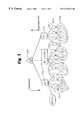
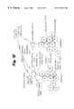
- FIG. 1illustrates the hierarchial communications network topology
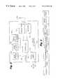
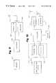
- FIG. 2is a network service module block diagram
- FIG. 3is a representative NSM-data packet
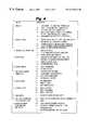
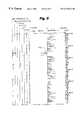
- FIG. 4is a listing or representative applications supported by the communications network
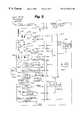
- FIG. 5is a schematic diagram of a network service module
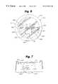
- FIG. 6shows a front elevation view of an electricity utility meter with a detection unit
- FIG. 7shows a bottom plan view of the electricity utility meter
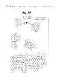
- FIG. 8is an illustration of a typical printout of information obtained by the network service module of FIG. 1;
- FIG. 9is a remote cell node block diagram
- FIG. 10is an intermediate data terminal block diagram
- FIG. 11is a central data terminal block diagram
- FIG. 12shows the configuration of the communications network for serving widely separated geographic areas
- FIG. 13illustrates a typical communications network with gradual growth in the number of areas served.
- a wide area communications networkcommunicates data from a plurality of network service modules to a central data terminal.
- the wide area communications networkcollects NSM data generated by a plurality of physical devices located within a geographical area.
- the wide area communications networkis a layered network having a hierarchial communications topology comprising a plurality of network service modules 110 , a plurality of remote cell nodes 112 , a plurality of intermediate data terminals 114 , and a central data terminal 120 .
- the physical devicesmay be, for example, a utility meter as used for electricity, gas or water.
- the central data terminalcontrols network operation. Intelligence exists at all layers of the network, thereby easing the workload of the central data terminal.
- the intelligence attributed to each moduleis a function of the application of that module.
- Network service modules 110include meter service modules for electricity, gas and water, a service disconnect module, a load management module, an alarm monitoring module, or any other module that can be used with the wide area communications network.
- the network service modules 110are linked to the wide area communications network via high frequency radio channels, typically in the 928 MHz-952 MHz band, as well as related frequencies in the 902 MHz-912 MHz and 918 MHz-928 MHz bands.
- Radio channels in these bandsare the preferred communications medium because use of radio communications eliminates the need for physical connections to the service modules which drastically reduces installation costs compared to other communication media such as telephone, cable networks and power line carriers.
- operation in the high frequency bandspermits the use of small antennas so that retrofitting standard watt hour meters is simplified. Radio communication channels in other bands may work equally as well, however.
- the network service module (NSM) 110includes NSM-receiver means, NSM-transmitter means, NSM-processor means, NSM-memory means and an NSM antenna 322 .
- the NSM-transmitter means and the NSM-receiver meansare coupled to the NSM antenna 322 .
- the NSM-processor meansis coupled to the NSM-transmitter means, NSM-receiver means, NSM-memory means and the physical device.
- the physical deviceis shown as basic 320 and other sensors 322 , and application control interface 324 .
- the network service modulealso includes an AC power supply 310 and a back-up battery power supply 312 .
- the NSM-receiver meansis embodied as an NSM receiver 316 , and is optional. If an NSM receiver 316 is included with the network service module, then the NSM receiver 316 can be used for receiving a command signal, which includes signalling data.
- the command signalcan be transmitted at either a first carrier frequency or a second carrier frequency. Normally the first carrier frequency is used by the NSM-transmitter means for transmitting to a remote cell node. In a preferred embodiment, the NSM receiver 316 receives the command signal on the first carrier frequency for spectrum efficiency.
- the wide area communications networkcan operate using only a single carrier frequency, i.e., the first carrier frequency.
- the command signalcan provide a time reference for updating a local clock, and serve as a frequency reference to the network service module.
- Signalling datasuch as manage service disconnect or control loads, also may be sent from the remote cell node to the network service module using the command signal. While the network service modules could be polled by the command signal, in general, such polling is not required and preferably not used with the present invention.
- the NSM-processor meanswhich is embodied as an NSM controller 314 , arranges data from the physical device into packets of data, and transfers the data to the NSM-memory means which is embodied as an NSM memory 315 .
- the NSM controller 314may be a microprocessor or equivalent circuit for performing the required functions.
- the NSM controller 314uses the received command signal for adjusting and setting the first carrier frequency of the NSM transmitter.
- the NSM datamay include meter readings, time of use and other information or status from a plurality of sensors.
- the NSM controllers 314for each network service module throughout a geographical area, can be programmed to read all the corresponding utility meters or other devices being serviced by the network service module, respectively.
- the NSM controller 314can be programmed to read peak consumption at predetermined intervals, such as every 15 minutes, throughout a time period, such as a day.
- the NSM controller 314also can be programmed to track and store maximum and minimum sensor readings or levels throughout the time period, such as a day.
- the NSM memory 315stores NSM data from the physical device.
- NSM datamay include meter reading data and time of use (TOU) and other information or status from a plurality of sensors.
- the NSM memory 315may be random access memory (RAM) or any type of magnetic media or other memory storage devices known in the art.
- the NSM controller 314uses the received command signal for adjusting the first carrier frequency of the NSM transmitter 318 .
- the NSM-transmitter meansis embodied as an NSM transmitter 318 .
- the NSM transmitter 318transmits at a first carrier frequency the respective NSM data from the physical device in brief message packets called an NSM-packet signal.
- the NSM-packet signalmight have a time duration of 100 milliseconds, although any time duration can be used to meet particular system requirements.
- the NSM-packet signal transmitted by the NSM transmitter 318follows a generic or fixed format, and a representative message packet is illustrated in FIG. 3 . Included in the message is: preamble; opening frame; message type; message identification; service module type; message number; service module address; data field; error detection; and closing frame.
- the NSM transmitter 318is connected to an NSM antenna 322 for transmitting multi-directionally the NSM-packet signals.
- the NSM transmitter 318includes a synthesizer or equivalent circuitry for controlling its transmitter carrier frequency and schedule.
- the NSM-packet signalis transmitted at a time which is randomly or pseudorandomly selected within a predetermined time period, i.e., using a one-way-random-access protocol, by the NSM-processor means.
- the wide area communications networkdoes not poll individual network service modules. Rather, each network service module report s autonomously at a rate appropriate for the application being supported. Routine reports are therefore transmitted randomly or pseudorandomly at fixed average intervals, while alarm signals are transmitted immediately following detection of alarm conditions. Alarm signals may be transmitted several times with random delays. This avoids interference among alarm messages if many alarms occur simultaneously, as in an area-wide power outage.
- the network service modulemay be programmed to transmit three different types of messages at different intervals.
- the first type of messagecan relate to the accumulated usage information.
- the second type of messagecan relate to an alarm condition which is basically transmitted immediately.
- the alarm conditions that occurmight relate to a tamper action or to the absence of electrical voltage indicative of a power failure.
- the third type of information which may be transmitted less frequentlycan relate to the housekeeping information.
- the controller 314After preparing the packet of data for transmission, the controller 314 is arranged to hold the data packet for a random period of time.
- This random periodcan be calculated using various randomizing techniques including, for example, a psuedo-random sequence followed, for example, by an actual random calculation based upon the rotation of the metering disk at any particular instant.
- each of the network service modulesis arranged to transmit at a random time.
- the controller 314is arranged so that the transmission does not occur within a particular predetermined quiet time so that none of the network service modules is allowed to transmit during this quiet time.
- This quiet timecould be set as one hour in every eight hour period. In this way after an eight hour period has elapsed, each of the network service modules would transmit at a random time during the subsequent seven hours followed by a quiet one hour.
- Network capacity or throughputis limited by the probability of message collisions at each remote cell node 112 . Because all network service modules 110 share a single carrier channel and transmit at random times, it is possible for several network service modules 110 within a range of a particular remote cell node 112 to transmit simultaneously and to collide at the remote cell node. If the received signal levels are comparable, the overlapping messages will mutually interfere, causing receive errors and both messages will be lost. However, if one signal is substantially stronger than the other, the stronger signal will be successfully received. Moreover, since both signals are received by at least two and preferably four of the remote cell nodes, the probability of both messages being received is fairly high unless the network service modules are in close spatial proximity. During an interval T, each transmitter within a cell surrounding a single remote cell node sends a single randomly timed message of duration M to several potential receive stations.
- Mmessage duration (seconds)
- T istarts transmitting the probability that another particular transmitter, T j , will complete or start another transmission is 2 ⁇ M T .
- the probability that there will be no collisionis 1 - 2 ⁇ M T .
- P s( 1 - ( 2 ⁇ M ) ) N - 1 T )
- N Ps Pcl Pc2 Pc3100 .9979 .0021 4 ⁇ 10 ⁇ 6 8 ⁇ 10 ⁇ 9 200 .9958 .0042 1.6 ⁇ 10 ⁇ 5 6.4 ⁇ 10 ⁇ 8 500 .9896 .0104 10 ⁇ 4 10 ⁇ 6 1,000 .9794 .0206 4 ⁇ 10 ⁇ 4 8 ⁇ 10 ⁇ 6 2,000 .9591 .041 1.6 ⁇ 10 ⁇ 3 6.8 ⁇ 10 ⁇ 5 5,000 .9010 .099 9.8 ⁇ 10 ⁇ 3 9.7 ⁇ 10 ⁇ 4 10,000 .811 .189 3.5 ⁇ 10 ⁇ 2 6.7 ⁇ 10 ⁇ 3
- N Tthe number of transmitters, whose signal level exceeds the receiver noise level and can, therefore, be received reliably depends on:
- Propagation path lossis highly variable due to attenuation, reflection, refraction and scattering phenomena which are a function of terrain, building structures, and antenna location. Some of these parameters can even vary on a diurnal and seasonal basis.
- a statistical modelcan be developed to provide data by which determination can be made of the best location and number of remote cell nodes for a particular geographical location.
- the modelcan include data relating to house density the N ⁇ value defined above relating to the attenuation of the signal, the location and presence of trees.
- FIG. 4is an illustrative listing of applications supported by the network service module within the wide area communications network. The following is a detailed discussion of the electricity meter application.
- a network service module 110schematically is shown in FIG. 5 and is mounted in a suitable housing 211 illustrated in FIGS. 6 and 7 with the housing including suitable mounting arrangement for attachment of the housing into the interior of a conventional electricity meter 212 .
- Each network service moduleis coupled to a respective physical device.
- the physical deviceis an electricity meter 212 .
- the electricity meter 212includes an outer casing 213 which is generally transparent. Within the casing is provided the meter system which includes a disk 214 which rotates about a vertical axis and is driven at a rate dependent upon the current drawn to the facility. The numbers of turns of the disk 214 are counted by a counting system including mechanical dials 215 .
- the meteris of conventional construction and various different designs are well known in the art.
- An antenna 217is mounted on a bracket 216 carried on the housing inside the cover 213 .
- the antenna 217 as shownis arc-shaped extending around the periphery of the front face. Other antenna configurations are possible.
- the antenna 217is mounted within the cover 213 of the meter.
- the NSM antenna 217is mounted on the support structure itself of the network service module 110 .
- Thisenables the network service module 110 to be manufactured relatively cheaply as an integral device which can be installed simply in one action.
- thisprovides an NSM antenna 217 which can transmit only relatively short distances.
- the power levelis maintained in relatively low value of the order of 10-100 milliwatts, the energy for which can be provided by a smaller battery system which is relatively inexpensive.
- An NSM antenna 217 of this type transmitting at the above power levelwould have a range of the order of one to two kilometers.
- the network service module 110is in a sealed housing which prevents tampering with the sensors, microprocessor 220 and memory 221 located within the housing 211 .
- the network service moduleoptionally may include a detection device which uses the microprocessor 220 which has associated therewith a storage memory 221 .
- An essential sensoris for meter reading, for measuring the amount of electricity, amount of water or amount of gas consumed. Such a sensor alleviates having a meter reader person, by allowing the system to automatically report the amount of usage of the physical device.
- the wide area communications networksupports distributed automation functions including basic meter reading, time of use meter reading, service connect and disconnect operations, alarm reporting, theft of service reporting, load research, residential load control commercial and industrial load curtailment, and distributed supervisory control and data acquisition (SCADA). Furthermore, the wide area communications network is readily expandable to support new applications as they are developed.
- FIG. 6illustratively shows a temperature sensor 227 and a battery sensor 228 ; however, each sensor 227 , 228 may be substituted by or may be in addition to other possible sensors from the following representative listing of sensors.
- a tilt sensor 222detects movement of the housing through an angle greater than a predetermined angle so that once the device is installed indication can be made if the device is removed or if the meter is removed from its normal orientation.
- a field sensor 223detects the presence of an electric field. Unless there is power failure, the electric field sensor should continue to detect the presence of an electric field unless the meter is removed from the system.
- An acoustic sensor 224detects sound.
- the sounds detectedare transmitted through a filter 225 which is arranged to filter by analog or digital techniques the sound signal so as to allow to pass through only those sounds which have been determined by previous experimentation to relate to cutting or drilling action particularly on the cover.
- a magnetic sensor 226detects the presence of a magnetic field.
- a magnetic fieldis generated by the coils driving the disk 214 so that magnetic fields should always be present unless the meter has been by-passed or removed.
- the rate of rotation of the diskis dependent upon the magnetic field and, therefore, this rate of rotation can be varied by changing the magnetic field by applying a permanent or electromagnet in the area of the meter to vary the magnetic field.
- the sensor 226is, therefore, responsive to variations in the magnetic field greater than a predetermined amount so as to indicate that an attempt has been made to vary the magnetic field adjacent the disk to slow down the rotation of the disk.
- a heat sensor 227detects temperature so that the temperature associated with a particular time period can be recorded.
- a battery level sensoris indicated at 228 .
- the sensors 226 , 227 and 228communicate information through analog digital converter 328 to the microprocessor 220 .
- the information from sensors 227 and 228can be communicated to provide “housekeeping” status of the operation of the unit.
- the temperature sensor 227can be omitted if required and this information replaced by information gained from a public weather information source. In some cases the meter is located inside the building and hence the temperature will remain substantially constant whereas the outside temperature is well known to vary consumption quite dramatically.
- a consumption sensorcomprises a direct consumption monitor 229 which can be of a very simple construction since it is not intended to act as an accurate measure of the consumption of the electricity used.
- the direct consumption monitor 229can, therefore, simply be a device which detects the value of the magnetic field generated on the assumption this is proportional to the current drawn.
- the direct consumption value obtainedcan then be competed with a measurement of the consumption as recorded by the rotation of the disk 214 .
- the direct consumption monitor 229provides a sum of the consumption over a time period which is different from the consumption measured by rotation of the disk 214 by an amount greater than a predetermined proportion then the direct consumption monitor can be used to provide a tamper signal. This would be indicative for example of a mechanical tag applied to the disk to reduce recorded consumption.
- a reverse sensor 230detects reverse rotation of the disk 214 and provides an input to the microprocessor on detection of such an event.
- a cover sensor 231is used to detect the continual presence of the cover 213 .
- the cover sensorcomprises a light emitting diode (LED) 232 which generates a light beam which is then reflected to a photo diode 233 .
- the absence of the reflected beam at the photo diode 233is detected and transmitted as a tamper signal to the microprocessor.
- the reflected beamis generated by a reflective strip 234 applied on the inside surface of the cover adjacent the diode 232 as shown in FIG. 6 .
- the above sensorsthus act to detect various tampering events so that the presence of such tampering events can be recorded in the storage memory 221 under the control of the microprocessor 220 .
- the microprocessor 220also includes a clock signal generator 335 so that the microprocessor 220 can create a plurality of time periods arranged sequentially and each of a predetermined length.
- the time periodsare eight hours in length and the microprocessor 220 is arranged to record in each eight hour period the presence of a tamper event from one or more of the tamper signals.
- the series of the predetermined time periodsis recorded with the series allocated against specific dates and each eight hour period within the day concerned having a separate recording location within the storage memory 221 .
- One such seriesis shown in FIG. 8 where a number of tampering events 236 are indicated.
- the print-outthus indicates when any tampering event 236 has occurred and in addition then identifies which type of tampering event has taken place.
- the rotation of the disk 214also is detected to accurately record the number of rotations of the disk both in a forward and in a reverse direction.
- a table 237shows in graphical form the amount of rotation of a disk recorded in eight hour periods as previously described. For one period of time the disk is shown to rotate in a reverse direction 238 . Whenever the disk rotates in a reverse direction, the reverse rotation subtracts from the number of turns counted on the conventional recording system 215 shown in FIG. 6 .
- detection of the rotation of the diskis carried out by the provision of a dark segment 239 formed on the undersurface of the disk leaving the remainder of the disk as a reflective or white material.
- the detection systemthus provides a pair of light emitting diodes 240 , 241 which are positioned on the housing so as to direct light onto the underside of the disk.
- the light emitting diodes 240 , 241are angularly spaced around the disk.
- the diodesare associated with the photo diodes 242 , 243 which receive light when the disk is positioned so that the light from the associated light emitting diode 240 , 241 falls upon the reflective part of the disk and that light is cut off when the dark part of the disk 214 reaches the requisite location.
- one of the pairs of light emitting diodes 240 , 241 and photo diodes 242 , 243is used to detect the passage of the dark segment that is, of course, one rotation of the disk. The direction of rotation is then detected by checking with the other of the pairs as the dark segment reaches the first of the pairs as to whether the second pair is also seeing the dark segment or whether it is seeing the reflective part. Provided the sensors are properly spaced in relation to the dimension of the segment, therefore, this indicates the direction which the disk rotated to reach the position which is detected by the first pair of diodes.
- the sensorsare primarily in a sampling mode using an adaptive sensing rate algorithm.
- the dark or non-reflective segmentis 108° of arc and there is provided a 50° displacement between the sensors.
- the maximum rotation rateis of the order of 2 rps.
- a basic sample intervalcan be selected at 125 m/sec, short enough to ensure at least one dark sample is obtained from the dark segment.
- only the first pair of sensorsis sampled continuously.
- a second confirming sampleis obtained and the sample rate increased to 16 pps.
- the second sensoris sampled.
- the second sensorstill sees the dark segment then cw rotation is confirmed while if a light segment is observed then ccw rotation is indicated.
- the algorithmresults in a sample rate of 8 pps for 70% of a rotation and 16 pps for 30% of a rotation for the first pair of sensors plus two samples for direction sensing for the second pair.
- the diskrotates approximately 1.6 million times.
- the photo diode outputis sampled immediately before and immediately after the LED is activated. If light is sensed with the LED off, stray light is indicated an alarm may be initiated after confirming test.
- the lattermay include a test of other sensors such as the optical communication port sensor discussed hereinafter.
- communication from the meter reading unitis carried out by radio transmission from the microprocessor 220 through a modulation device 250 which connects to the antenna 322 .
- the transmission of the signalis carried under control of the microprocessor 220 .
- Modulation carried out by the modulation device 250can be of a suitable type including, for example, phase modulation using phase shift keying (PSK) such as binary PSK (BPSK), frequency modulation using frequency shift keying (FSK), such as, for example, binary FSK, or spread spectrum modulation in which the signals are modulated onto a number of separate frequencies at timed intervals so that no single frequency channel is used.
- PSKphase shift keying
- BPSKbinary PSK
- FSKfrequency shift keying
- spread spectrum modulationin which the signals are modulated onto a number of separate frequencies at timed intervals so that no single frequency channel is used.
- a plurality of remote cell nodes 112are located within the geographical area and are spaced approximately uniformly and such that each network service module 110 is within a range of several remote cell nodes 112 to provide overlapping coverage.
- the remote cell nodes 112typically might be spaced at 0.5 mile intervals on utility poles or light standards.
- Each remote cell node 112provides coverage over a limited area much like the cell in a cellular telephone network.
- Remote cell nodes 112preferably are spaced to provide overlapping coverage, so that on an average, each NSM-packet signal transmitted by a network service module 110 is received by three or four remote cell nodes 112 , even in the presence of temporary fading. As a consequence, erection of a tall building near a network service module 110 has little or no effect on message reception, nor does the failure of a remote cell node 112 result in loss of NSM-packet signals or NSM data.
- each remote cell node (RCN) 112 of FIG. 1includes RCN-transmitter means, RCN-transmitter means, RCN-receiver means, RCN-memory means, RCN-processor means and an RCN antenna 422 .
- the RCN-transmitter means, RCN-receiver means, RCN-memory means and RCN-processor meansmay be embodied as an RCN transmitter 418 , RCN receiver 416 , RCN memory 415 and RCN processor 414 , respectively.
- the RCN transmitter 418 and the RCN receiver 416are coupled to the RCN antenna 422 .
- the RCN processor 414is coupled to the RCN transmitter 418 , RCN receiver 416 , and RCN memory 415 .
- the RCN transmitter 418under the control of the RCN processor 414 , transmits at the first carrier frequency or the second carrier frequency a command signal.
- the choice of frequencydepends on which frequency is being used for the NSM receiver 316 at each of the plurality of network service modules 110 .
- Transmitting a command signal from the RCN transmitteris optional, and is used if the NSM receiver 316 is used at the network service module 110 .
- the command signalcan include signalling data being sent to network service modules 110 .
- the signalling datamay require the network service module 110 to transmit status or other data; set reporting time period, e.g. from an eight hour period to a four hour period; and any other command, control or “housekeeping” jobs as required.
- the RCN receiver 416receives at the first carrier frequency a multiplicity of NSM-packet signals transmitted from a multiplicity of network service modules 110 .
- Each of the multiplicity of NSM-packet signalstypically are received at different points in time, since they are transmitted at a time which is randomly or pseudorandomly selected within the predetermined time period.
- the multiplicity of network service modules 110usually is a subset of the plurality of network service modules 110 .
- Received NSM-packet signalsare time stamped by the RCN processor 414 and temporarily stored in the RCN memory 415 before being transmitted to the next higher network level.
- the RCN receiver 416also receives polling signals from the intermediate data terminal, and listens or eavesdrops on neighboring remote cell nodes when they are polled by the intermediate data terminal.
- the RCN processor 414collates the NSM-packet signals received from the network service modules, identifies duplicates of NSM-packet signals and deletes the duplicate NSM-packet signals.
- the RCN processor 414controls the RCN transmitter 418 and RCN receiver 416 .
- the RCN memory 415stores the received multiplicity of NSM-packet signals.
- each remote cell node 112receives, decodes and stores in RCN memory 415 each of these NSM-packet signals as received from the network service modules 110 .
- the remote cell nodecomprises simply a suitable resistant casing which can be mounted upon a building, lamp standard or utility pole at a suitable location in the district concerned.
- the remote cell nodecan be battery powered with a simple omni-directional antenna as an integral part of the housing or supported thereon.
- An intermediate data terminal 114Information accumulated at remote cell nodes 112 periodically is forwarded via a polled radio communications link to a higher level network node, as illustrated in FIG. 1, termed an intermediate data terminal 114 .
- the intermediate data terminals 114are spaced typically at 4 mile intervals and can be conveniently sited at substations, providing coverage for up to 100 cells.
- Remote cell nodesalso receive timing information and command signals from intermediate data terminals.
- the RCN transmitter 418transmits at the first carrier frequency the stored multiplicity of NSM-packet signals as an RCN-packet signal to the intermediate data terminal 114 .
- neighboring remote cell nodes 112When a first remote cell node is polled with a first polling signal by the intermediate data terminal, neighboring remote cell nodes 112 receive the RCN-packet signal transmitted by the first remote cell node. Upon receiving an acknowledgment signal from the intermediate data terminal that polled the first remote cell node, at the neighboring remote cell nodes 112 the respective RCN processor deletes from the respective RCN memory messages from the network service modules that have the same message identification number as messages transmitted in the RCN-packet signal from the first remote cell node to the intermediate data terminal. The message identification number is illustrated in a typical NSM-data packet in FIG. 3 .
- FIG. 1illustrates a plurality of the network service modules 110 .
- the network service modules 110are set out in a pattern across the ground which is dependent upon the positions of the utility usage which generally does not have any particular pattern and the density will vary significantly for different locations.
- the remote cell nodes 112are arranged in an array with the spacing between the remote cell nodes 112 relative to the network service modules 110 so that each remote cell node 112 can transmit to at least two and preferably four of the remote cell nodes 112 .
- the remote cell nodes 112are provided in significantly larger numbers than is absolutely necessary for each network service module 110 to be received by a respective one of the remote cell nodes 112 .
- the remote cell nodes 112theoretically receive high levels of duplicate information. In a normal residential situation, the location of the remote cell nodes 112 so that each network service module 110 can be received by four such remote cell nodes 112 would lead to an array in which each remote cell node 112 would be responsive to approximately 1,000 of the network service modules 110 .
- Each of the network service modules 110is arranged to calculate an accumulated value of utility usage for a set period of time which in the example shown is eight hours. Subsequent to the eight hour period, the NSM controller 314 prepares to transmit the information in a packet of data as an NSM-packet signal.
- the packet of dataincludes:
- the RCN controller 414acts to store the information received in the RCN memory 415 and then to analyze the information.
- the first step in the analysisis to extract from the received messages the identification code relating to the respective network service module 110 .
- the information relating to that network service module 110is introduced into a RCN memory register relating to that network service module 110 to update the information already stored.
- each remote cell node 112monitors the transmissions of the other remote cell nodes 112 .
- the information transmittedis compared with information stored in any other remote cell node 112 doing the monitoring and if any information is found in the memory of the remote cell node 112 which is redundant, that information is then canceled. In this way when very high levels of redundancy are used, the time for transmission from the remote cell node 112 to the intermediate data terminal is not significantly increased.
- each network service module 110can be arranged to transmit an alarm signal upon detection of the removal of the electric voltage.
- the transmission of the alarm signalcan be delayed by a short random period of time so that if the loss of the voltage is due to a power outage covering a number of locations all signals are not received at the same time.
- the remote cell nodes 112 and intermediate data terminals 114also can be programmed to retransmit such alarm signals immediately. In this way the central data terminal 120 has immediate information concerning any power outages including the area concerned. This can, of course, enable more rapid repair functions to be initiated.
- the remote cell nodes 112can be arranged to transmit control signals for operating equipment within the premises in which the network service module 110 is located.
- the remote cell nodes 112are necessarily arranged in a suitable array to transmit such information so that it is received in each of the premises concerned using again relatively low transmission power and using the equipment provided for the meter reading system.
- This transmission capabilitycan be used to control, for example, radio controlled switches within the premises of relatively high power equipment for load shedding at peak periods.
- the network service module 110may include a receiving facility to enable detection of signals transmitted by the remote cell nodes 112 .
- these signalsmay relate to synchronizing signals so that each of the network service modules 110 is exactly synchronized in time with the remote cell node 112 and/or intermediate data terminal 114 and central data terminal 120 .
- This exact synchronizationcan be used for accurately detecting usage during specific time periods so that the utility may charge different rates for usage during different time periods for the purpose of particularly encourage use at non-peak times again for load shedding purposes.
- the attenuation of a radio signalis proportional to the inverse of the distance from the source to the power N.
- NIn free space N is equal to 2.
- This effecttherefore, significantly reduces the distance over which the signal from the network service module can be monitored.
- the number of network service modulesis significantly reduced which can be monitored by a single remote cell node.
- the large Nrapidly reduces the signal strength after a predetermined distance so that while a network service module can be effectively monitored at a certain distance, the signal strength rapidly falls off beyond that distance.
- An advantage of the present systemis that network service modules 110 which are located at a position which is geographically very disadvantageous for transmission to the closest remote cell node 112 may be monitored by a different one of the remote cell nodes 112 .
- some of the network service modules 110may not be monitored at all in view of some particular geographical problem.
- this possibilityis significantly reduced by the fact that the network service module 110 concerned is likely to be in a position to be monitored by a larger number of the remote cell nodes 112 so that the geographical problem most probably will not apply to all of the remote cell nodes.
- the increased density of remote cell nodes 112permits the network service modules 110 to operate with an integral NSM antenna 322 which can be formed as part of the meter reading unit housed within the conventional electric utility meter.
- the network service module 110can be totally self contained within the meter housing thus allowing installation within a very short period of time, avoiding customer dissatisfaction caused by wiring problems and reducing the possibility of damage to a separately mounted NSM antenna 322 .
- this arrangementsignificantly reduces the cost of the network service module 110 to a level which is economically viable to allow installation of the system.
- the present inventioncan employ a system in which the network service modules 110 are permitted to transmit only during a predetermined time period so that an open time period is available for communication on the same frequency between the intermediate data terminal 114 and the remote cell node 112 without any interference from the remote cell nodes 112 .
- This level of communicationcan be carried out using a polling system from the intermediate data terminals 114 to each of the remote cell nodes 112 in turn preferably including a directional transmission system at the intermediate data terminal 114 .
- This systemallows optimization of the remote cell node 112 density to meet cost/performance criteria in different deployment scenarios.
- the present inventionby recognizing the non-volatile nature of the information source and the acceptability of missing an occasional update through transmission errors or collisions enables the implementation of data collection networks of greater simplicity and at lower cost than is possible with established communication network approaches involving two-way communication.
- the present inventiontherefore, provides a radio communication network which can be employed to acquire data from a large number of remote meter monitoring devices disposed over a wide area using very low power transmitters in conjunction with an array of remote cell nodes all operating on a single radio communication channel or frequency.
- the plurality of intermediate data terminals 114are located within the geographic area and are spaced to form a grid overlaying the geographic area.
- the intermediate data terminals 114typically are spaced to cover large geographic areas.
- Intermediate data terminals 114preferably are spaced to provide overlapping coverage, so that on an average, an RCN-packet signal transmitted from a remote cell node 112 is received by two or more intermediate data terminals.
- each intermediate data terminal 114includes first IDT-transmitter means, second IDT-transmitter means, IDT-memory means, IDT-processor means, first IDT-receiver means, second IDT-receiver means and an IDT antenna.
- the first IDT-transmitter means, second IDT-transmitter means, IDT-memory means, IDT-processor means, first IDT receiver means and second IDT-receiver meansmay be embodied as a first IDT transmitter 518 , second IDT transmitter 519 , IDT memory 515 , IDT processor 514 , first IDT receiver 521 and second IDT receiver 522 , respectively.
- the first IDT transmitter 518 and the first IDT receiver 521are coupled to the IDT antenna 522 .
- the IDT processor 514is coupled to the first and second IDT transmitters 518 , 519 , the first and second IDT receivers 521 , 522 and IDT memory 515 .
- the second IDT transmitter 519 and second IDT receiver 522may be embodied as a device such as a modem 523 .
- the first IDT transmitter 518under the control of the IDT processor 514 , includes a synthesizer or equivalent circuitry for controlling the carrier frequency, and allowing the first IDT transmitter 518 to change carrier frequency.
- the first IDT transmitter 518transmits preferably at the first carrier frequency, or the second carrier frequency, the first polling signal using a first polling-access protocol to the plurality of remote cell nodes 112 .
- that remote cell noderesponds by sending the RCN-packet signal to the intermediate data terminal 114 which sent the first polling signal. If the intermediate data terminal 114 successfully receives the RCN-packet-signal, then the first IDT transmitter 518 sends an acknowledgment signal to the remote cell node.
- the RCN processor 414 at that remote cell nodedeletes, from the RCN memory 415 , the data sent in the RCN-packet signal to the intermediate data terminal.
- Intermediate data terminals 114also communicate timing information and command signals to remote cell nodes 112 .
- Remote cell nodes 112 serving important SCADA functionscan be polled more frequently by an intermediate data terminal 114 to reduce network response time.
- the first IDT receiver 521receives the RCN-packet signal transmitted at the first carrier frequency from the remote cell node which was polled. Thus, after sequentially polling a plurality of remote cell nodes 112 , the first IDT receiver 521 has received sequentially in time a plurality of RCN-packet signals.
- the IDT memory 515stores the received RCN-packet signals.
- the IDT processor 514collates the NSM-packet signals embedded in the RCN-packet signals received from the plurality of remote cell notes, identifies duplicates of NSM-packet signals and deletes the duplicate NSM-packet signals, i.e., messages from network service modules that have the same message identification number.
- the second IDT transmitter 519transmits a plurality of RCN-packet signals as an IDT-packet signal to the central data terminal 120 .
- the second IDT transmitter 519 and second IDT receiver 522may be embodied as a modem 523 or other device for communicating information over a communications medium 525 linking the intermediate data terminal with the central data terminal.
- the intermediate data terminals 114may include one or more directional antennas 522 . During the quiet time, the intermediate data terminal 114 is arranged to direct the antenna 522 or antennas to each of the remote cell nodes 112 in turn and to transmit to the respective remote cell node 112 the first polling signal calling for the remote cell node 112 to transmit the stored information from the RCN memory 415 . Use of more than one antenna can allow communication with more than one remote cell node 112 at a time. The remote cell node 112 is required, therefore, merely to transmit the information upon request in a collated package of the information which is transmitted to the intermediate data terminal 114 and collected for analysis.
- a central data terminal 120which acts as a network control center and data consolidation point.
- the central data terminal 120controls basic network operation, allowing it to make global decisions regarding network organization.
- the central data terminal's purposeis to integrate information from a variety of network nodes into a coherent form which may be forwarded to different utility operating groups for specific applications.
- the central data terminal 120is connected to critical SCADA sites some of which may be co-located with intermediate data terminals 114 at sub-stations. At this level, there are relatively few communication links, so those required can be selected to optimize cost, speed and reliability.
- the transmission between the central data terminal 120 and the plurality of intermediate data terminals 114is carried out using a communications medium 525 such as telephone lines, T 1 carriers, fiber ontic channels, coaxial cable channels, microwave channels, or satellite links.
- the central data terminal (CDT) 120includes CDT-transmitter means, CDT-receiver means, CDT-processor means and CDT-memory means.
- the CDT-transmitter means, CDT-receiver means, CDT-processor means and CDT-memory meansmay be embodied as a CDT transmitter 618 , CDT receiver 616 , CDT processor 614 and CDT memory 615 , respectively.
- the CDT transmitter 618 and CDT receiver 616are coupled to the communications medium 525 .
- the CDT processor 614is coupled to the CDT transmitter 618 , CDT receiver 616 and CDT memory 615 .
- the CDT transmitter 618 and CDT receiver 616may be a modem 625 or other device suitable for communicating information over the communications medium 525 between the central data terminal 120 and each intermediate data terminal 114 .
- the CDT transmitter 618transmits sequentially in time the second polling signal using a second polling access protocol to the plurality of intermediate data terminals 114 .
- the CDT receiver 616receives a plurality of IDT-packet signals.
- the CDT processor 614decodes the plurality of IDT-packet signals as a plurality of NSM data.
- the CDT processor 614also identifies duplicates of NSM data and deletes the duplicate NSM data.
- the CDT memory 615stores the NSM data in a data base. The NSM data is outputted, analyzed or processed as desired.
- the performance of the networkis in large part determined by the network service module 110 to remote cell node 112 link performance, which is defined by the network service module message loss rate.
- the network architectureis designed to minimize the network service module message loss rate, which is defined as the fraction of transmitted network service module messages which are not received by the remote cell nodes. The two issues that affect the message loss rate are:
- the collision issueis resolved using:
- Remote cell node spacingcan be selected to control the path redundancy, thus leading to an adjustable level of performance. Notice that path redundancy and multiple transmission per day are used to resolve both issues, and thus are principle features of the wide area communications network. The effect of collisions is minimal, so the probability of receiving a packet any time during the day is maintained at exceptionally high levels.
- the link budgetcontains all of the gains and losses between the network service module power amplifier and the remote cell node receiver, and is used to calculate the maximum pathloss which can be allowed on any link.
- the minimum receivable signal at the remote cell nodeis estimated as ⁇ 115 dBm, which is equal to the sum of the noise floor and the carrier to noise level which is required in order to receive the message (10 dB).
- Every network service modulehas many remote cell nodes within receiving range, which increases the reliability of packet reception.
- a network service moduletransmits it has the potential to be received by many remote cell nodules.
- Some of the remote cell nodulesare in shadow fading zones and do not receive the signal whereas others have an increased signal due to shadowing.
- the urban landscapechanges due to building construction and demolition and foliage growth. These changes in landscape affect the network service module-remote cell node links, causing some remote cell nodes to no longer receive the network service module while new remote cell nodes do receive the network service module. For each link that is no longer available it is expected that a new link becomes operational.
- the wide area communications networkcan readily and cost effectively expand to support new hardware and application software growth scenarios.
- the wide area communications networkcan be implemented in those regions of the user's service territory and for those services which are most needed on an implementation plan which is not affected by geographic distribution.
- FIG. 12illustrates the configuration of the wide area communications network for serving widely separated geographic areas. This includes the provision of wide area communications network services to isolated smaller communities via satellite, fibre optic, microwave or other back bone network. Due to the unique nature of wide area communications network's single channel, micro cellular scattering propagation concept, it is immune to traditional radio problems such as fading, nulls, multi-path, lack of line of sight typical of mountainous, hilly, valley or high density urban setting.
- the wide area communications networksupports a broad range of monitoring, verifiable control and fast response transaction applications. A number of these application needs are and continue to be identified by utilities. Due to the standardized network interface protocol and message packet configuration, the wide area communications network is able to readily augment its service offerings in either new hardware or software.
- the wide area communications networkoffers not only specialized network service modules for electric, gas and water meters but also provides a series of generic modules with industry standard in/output interfaces for contact closure, voltage or current sensing. This allows a variety of vendors to incorporate a wide area communications network communication interface into their own products be they fuses, alarms, temperature sensors, etc.
- the wide area communications networkcan provide a single integrated data channel for other utility operational applications. Some of these applications are hardware oriented but many are application software oriented. They involve the generation of new value-added information reports or services. Although some are primarily for use by the utility, many of them could be offered for sale to the customer thus resulting in a new revenue stream for the utility.
- the wide area communications networkcan support the expansion of SCADA due to its highly reliable wireless communication capabilities. Many utilities would like to add instrumental monitoring points to their SCADA, however, the wiring costs or difficulties often associated with these prohibits SCADA growth at a sub-station or other site. Generic network service modules could be used to solve these problems.
- the hierarchical design of wide area communications networkallows the customer to service an arbitrarily large contiguous or non-contiguous geographic area, as shown in FIG. 12, containing many applications and a large number of end points.
- the hierarchical design of the networkallows non-contiguous areas to be serviced over a wide geographic area. Separate areas have their own intermediate data terminal communicating with the central data terminal. Data from non-contiguous areas would be transferred at the central data terminal level.
- FIG. 13illustrates a typical communications network with gradual growth in the number of areas served.
- Wide area communications networkprovides over one trillion serial numbers for each type of service module, which allows unique module identification over the life of the system.
- Centralized control of wide area communications networkis achieved by allowing the central data terminal to have access to network status data, which it uses to make decisions regarding network optimization. These decisions are downloaded to the intermediate data terminals and remote cell nodes as required.
- Centralized traffic controlis achieved at the remote cell node and intermediate data terminal levels by using priority tables, message storage instructions and alarm storage instructions.
- priority tablesThe structure of the priority tables is described as follows.
- each message that is transferred through the systemthere is a set of identification tags stating the message type and the source.
- the priority tables in the remote cell nodes 112 and intermediate data terminals 114contain a listing of all identification tags in the system and the priority tables are first installed at the time of deployment, but can be updated from the central data terminal 120 as required. During the network operational period there may be a need to change message priorities, which can then be performed with minimal impact on the network traffic.
- Control of the alarm traffic within the networkrequires another table because alarm reporting generates higher traffic levels for a short period of time. This bursty traffic generation can lead to congestion problems, and so an alarm instruction table allows the central data terminal to clear alarm messages out of remote cell node and intermediate data terminal buffers at the end of the alarm. This priority table also allows the utility to tailor the alarm traffic delay to suit its particular needs.
- Both the priority tables and the alarm instructionsare used by the message storage instruction module to properly manage traffic on the network.
- the message storage instructionsmaintain the message queue, ensure that response times are within specification, and transmit performance data to the central data terminal to be used for network control.
- the network service modulestransmit messages to the remote cell nodes, which then use the tables discussed above to organize the message queue. All messages reach the application switch with the specified delay.
- the central data terminaldownloads data to the three control modules and tables as required.
Landscapes
- Engineering & Computer Science (AREA)
- Computer Networks & Wireless Communication (AREA)
- Physics & Mathematics (AREA)
- General Physics & Mathematics (AREA)
- Signal Processing (AREA)
- Power Engineering (AREA)
- Environmental & Geological Engineering (AREA)
- Arrangements For Transmission Of Measured Signals (AREA)
- Mobile Radio Communication Systems (AREA)
Abstract
Description


| N | Ps | Pcl | Pc2 | Pc3 |
| 100 | .9979 | .0021 | 4 × 10⁻⁶ | 8 × 10⁻⁹ |
| 200 | .9958 | .0042 | 1.6 × 10⁻⁵ | 6.4 × 10⁻⁸ |
| 500 | .9896 | .0104 | 10−4 | 10−6 |
| 1,000 | .9794 | .0206 | 4 × 10⁻⁴ | 8 × 10⁻⁶ |
| 2,000 | .9591 | .041 | 1.6 × 10⁻³ | 6.8 × 10⁻⁵ |
| 5,000 | .9010 | .099 | 9.8 × 10⁻³ | 9.7 × 10⁻⁴ |
| 10,000 | .811 | .189 | 3.5 × 10⁻² | 6.7 × 10⁻³ |
Claims (32)
Priority Applications (4)
| Application Number | Priority Date | Filing Date | Title |
|---|---|---|---|
| US09/296,359US6172616B1 (en) | 1990-02-15 | 1999-04-22 | Wide area communications network for remote data generating stations |
| US09/687,785US6373399B1 (en) | 1990-02-15 | 2000-10-13 | Wide area communications network for remote data generating stations |
| US09/960,800US6653945B2 (en) | 1990-02-15 | 2001-09-21 | Radio communication network for collecting data from utility meters |
| US10/024,977US20030001754A1 (en) | 1990-02-15 | 2001-12-19 | Wide area communications network for remote data generating stations |
Applications Claiming Priority (6)
| Application Number | Priority Date | Filing Date | Title |
|---|---|---|---|
| US07/480,573US5056107A (en) | 1990-02-15 | 1990-02-15 | Radio communication network for remote data generating stations |
| US73218391A | 1991-07-19 | 1991-07-19 | |
| US12449593A | 1993-09-22 | 1993-09-22 | |
| US08/271,545US5553094A (en) | 1990-02-15 | 1994-07-07 | Radio communication network for remote data generating stations |
| US08/454,678US5963146A (en) | 1990-02-15 | 1995-05-31 | Wide area communications network for remote data generating stations |
| US09/296,359US6172616B1 (en) | 1990-02-15 | 1999-04-22 | Wide area communications network for remote data generating stations |
Related Parent Applications (1)
| Application Number | Title | Priority Date | Filing Date |
|---|---|---|---|
| US08/454,678ContinuationUS5963146A (en) | 1990-02-15 | 1995-05-31 | Wide area communications network for remote data generating stations |
Related Child Applications (1)
| Application Number | Title | Priority Date | Filing Date |
|---|---|---|---|
| US09/687,785ContinuationUS6373399B1 (en) | 1990-02-15 | 2000-10-13 | Wide area communications network for remote data generating stations |
Publications (1)
| Publication Number | Publication Date |
|---|---|
| US6172616B1true US6172616B1 (en) | 2001-01-09 |
Family
ID=27383115
Family Applications (6)
| Application Number | Title | Priority Date | Filing Date |
|---|---|---|---|
| US08/271,545Expired - LifetimeUS5553094A (en) | 1990-02-15 | 1994-07-07 | Radio communication network for remote data generating stations |
| US08/454,678Expired - LifetimeUS5963146A (en) | 1990-02-15 | 1995-05-31 | Wide area communications network for remote data generating stations |
| US09/296,359Expired - LifetimeUS6172616B1 (en) | 1990-02-15 | 1999-04-22 | Wide area communications network for remote data generating stations |
| US09/687,785Expired - LifetimeUS6373399B1 (en) | 1990-02-15 | 2000-10-13 | Wide area communications network for remote data generating stations |
| US09/960,800Expired - Fee RelatedUS6653945B2 (en) | 1990-02-15 | 2001-09-21 | Radio communication network for collecting data from utility meters |
| US10/024,977AbandonedUS20030001754A1 (en) | 1990-02-15 | 2001-12-19 | Wide area communications network for remote data generating stations |
Family Applications Before (2)
| Application Number | Title | Priority Date | Filing Date |
|---|---|---|---|
| US08/271,545Expired - LifetimeUS5553094A (en) | 1990-02-15 | 1994-07-07 | Radio communication network for remote data generating stations |
| US08/454,678Expired - LifetimeUS5963146A (en) | 1990-02-15 | 1995-05-31 | Wide area communications network for remote data generating stations |
Family Applications After (3)
| Application Number | Title | Priority Date | Filing Date |
|---|---|---|---|
| US09/687,785Expired - LifetimeUS6373399B1 (en) | 1990-02-15 | 2000-10-13 | Wide area communications network for remote data generating stations |
| US09/960,800Expired - Fee RelatedUS6653945B2 (en) | 1990-02-15 | 2001-09-21 | Radio communication network for collecting data from utility meters |
| US10/024,977AbandonedUS20030001754A1 (en) | 1990-02-15 | 2001-12-19 | Wide area communications network for remote data generating stations |
Country Status (1)
| Country | Link |
|---|---|
| US (6) | US5553094A (en) |
Cited By (166)
| Publication number | Priority date | Publication date | Assignee | Title |
|---|---|---|---|---|
| US20010039537A1 (en)* | 1997-02-12 | 2001-11-08 | Carpenter Richard Christopher | Network-enabled, extensible metering system |
| US6370489B1 (en)* | 1997-04-16 | 2002-04-09 | A.L. Air Data | Lamp monitoring and control system and method |
| US6400161B1 (en)* | 2001-05-23 | 2002-06-04 | Donald Joseph Geisel | Material segregation and density analyzing apparatus and method |
| US20020125998A1 (en)* | 1998-06-22 | 2002-09-12 | Petite Thomas D. | System and method for monitoring and controlling remote devices |
| EP1246501A2 (en) | 2001-03-28 | 2002-10-02 | Techem Service Aktiengesellschaft & Co. KG | Method and apparatus for reading of utility meters |
| US20020145537A1 (en)* | 2001-01-25 | 2002-10-10 | Wilfred Mueller | Systems and methods for wirelessly transmitting data from a utility meter |
| US6512463B1 (en)* | 1999-03-30 | 2003-01-28 | American Meter Co. | Bi-directional protocol |
| KR20030018801A (en)* | 2001-08-31 | 2003-03-06 | 이긍재 | Rf transmitter system of instrumentation data |
| US20030179714A1 (en)* | 2002-03-21 | 2003-09-25 | Gilgenbach Alan M. | Meter monitoring and tamper protection system and method |
| US6650249B2 (en) | 1998-05-01 | 2003-11-18 | Elster Electricity, Llc | Wireless area network communications module for utility meters |
| US20030218614A1 (en)* | 2002-03-12 | 2003-11-27 | Lavelle Michael G. | Dynamically adjusting sample density in a graphics system |
| US20040001008A1 (en)* | 2002-06-27 | 2004-01-01 | Shuey Kenneth C. | Dynamic self-configuring metering network |
| US6684245B1 (en) | 1997-04-08 | 2004-01-27 | Elster Electricity, Llc | Automatic meter reading system employing common broadcast command channel |
| US6700902B1 (en) | 1998-10-19 | 2004-03-02 | Elster Electricity, Llc | Method and system for improving wireless data packet delivery |
| US20040114737A1 (en)* | 2002-11-27 | 2004-06-17 | Macconnell John Walter | Telemetry system and method |
| US20040131125A1 (en)* | 2001-03-30 | 2004-07-08 | Advanced Metering Data Comm. Systems, L.L.C. | Enhanced wireless packet data communication system, method, and apparatus applicable to both wide area networks and local area networks |
| US6782351B2 (en) | 2001-09-11 | 2004-08-24 | Purechoice, Inc. | Air quality monitoring and space management system coupled to a private communications network |
| US20040218616A1 (en)* | 1997-02-12 | 2004-11-04 | Elster Electricity, Llc | Remote access to electronic meters using a TCP/IP protocol suite |
| US20050017847A1 (en)* | 2003-07-24 | 2005-01-27 | Bonicatto Damian G. | Power line communication system having time server |
| US20050020232A1 (en)* | 2003-07-24 | 2005-01-27 | Bonicatto Damian G. | Data communication over power lines |
| US20050043059A1 (en)* | 2000-08-09 | 2005-02-24 | Petite Thomas D. | Systems and methods for providing remote monitoring of electricity consumption for an electric meter |
| US20050055586A1 (en)* | 2003-07-24 | 2005-03-10 | Hunt Technologies, Inc. | Endpoint event processing system |
| US20050052288A1 (en)* | 2003-09-05 | 2005-03-10 | Osterloh Christopher L. | Sequence inversion keyed countdown timer utilized within a utility meter system |
| US6867707B1 (en) | 2002-04-24 | 2005-03-15 | Elster Electricity, Llc | Automated on-site meter registration confirmation using a portable, wireless computing device |
| US20050086182A1 (en)* | 2003-09-05 | 2005-04-21 | Christopher Nagy | Optimized bubble up receiver AMR system |
| US20050083925A1 (en)* | 2003-07-24 | 2005-04-21 | Bonicatto Damian G. | Locating endpoints in a power line communication system |
| US20050146999A1 (en)* | 2003-11-26 | 2005-07-07 | Mitsumi Electric Co., Ltd. | Objective lens driving device enabling speed-up of optical disk drive |
| US20050162283A1 (en)* | 2001-08-17 | 2005-07-28 | Salazar Cardozo Ruben E. | Fixed-network system for automatic meter reading having a one-way local area network |
| US20050172024A1 (en)* | 2004-01-26 | 2005-08-04 | Tantalus Systems Corp. | Communications system |
| US20050179561A1 (en)* | 2003-05-07 | 2005-08-18 | Osterloh Christopher L. | Applications for a low cost receiver in an automatic meter reading system |
| US20050183647A1 (en)* | 2003-06-09 | 2005-08-25 | Fabtex Graphics Inc. | Process and components for applying appliques |
| US20050193432A1 (en)* | 2003-11-18 | 2005-09-01 | Whitehead Institute For Biomedical Research | Xenograft model of functional normal and malignant human breast tissues in rodents and methods thereof |
| US20050195775A1 (en)* | 2004-03-03 | 2005-09-08 | Petite Thomas D. | System and method for monitoring remote devices with a dual-mode wireless communication protocol |
| US20050206366A1 (en)* | 2004-03-18 | 2005-09-22 | Shuey Kenneth C | Bias technique for electric utility meter |
| US20050206365A1 (en)* | 2004-03-18 | 2005-09-22 | Shuey Kenneth C | Reducing power consumption of electrical meters |
| US20050206530A1 (en)* | 2004-03-18 | 2005-09-22 | Cumming Daniel A | Solar powered radio frequency device within an energy sensor system |
| US20050239414A1 (en)* | 2004-04-26 | 2005-10-27 | Mason Robert T Jr | Method and system for configurable qualification and registration in a fixed network automated meter reading system |
| US20050240540A1 (en)* | 2004-04-26 | 2005-10-27 | Borleske Andrew J | System and method for efficient configuration in a fixed network automated meter reading system |
| US20050237221A1 (en)* | 2004-04-26 | 2005-10-27 | Brian Brent R | System and method for improved transmission of meter data |
| US20050251403A1 (en)* | 2004-05-10 | 2005-11-10 | Elster Electricity, Llc. | Mesh AMR network interconnecting to TCP/IP wireless mesh network |
| US20050251401A1 (en)* | 2004-05-10 | 2005-11-10 | Elster Electricity, Llc. | Mesh AMR network interconnecting to mesh Wi-Fi network |
| US20050259580A1 (en)* | 2004-04-26 | 2005-11-24 | Christopher Osterloh | Fixed network utility data collection system and method |
| US20050270173A1 (en)* | 2003-02-14 | 2005-12-08 | Boaz Jon A | Automated meter reading system, communication and control network for automated meter reading, meter data collector program product, and associated methods |
| US20050278440A1 (en)* | 2004-06-15 | 2005-12-15 | Elster Electricity, Llc. | System and method of visualizing network layout and performance characteristics in a wireless network |
| US6983378B1 (en)* | 1999-01-18 | 2006-01-03 | Nec Corporation | Data storage device and detection method |
| US20060009927A1 (en)* | 2004-07-07 | 2006-01-12 | Osterloh Christopher L | Dual source real time clock synchronization system and method |
| US7012546B1 (en) | 2001-09-13 | 2006-03-14 | M&Fc Holding, Llc | Modular wireless fixed network for wide-area metering data collection and meter module apparatus |
| US20060056370A1 (en)* | 2003-07-18 | 2006-03-16 | Hancock Martin A | Data integrity in a mesh network |
| US20060066455A1 (en)* | 2003-07-18 | 2006-03-30 | Hancock Martin A | Grouping mesh clusters |
| US20060069661A1 (en)* | 2004-09-24 | 2006-03-30 | Scoggins Sean M | System and method for automated configuration of meters |
| US20060071812A1 (en)* | 2002-06-28 | 2006-04-06 | Elster Electricity Llc | Data collector for an automated meter reading system |
| US20060071811A1 (en)* | 2004-09-24 | 2006-04-06 | Christopher Russell G | System and method for creating multiple operating territories within a meter reading system |
| US20060072465A1 (en)* | 2004-09-24 | 2006-04-06 | Scoggins Sean M | System for automated management of spontaneous node migration in a distributed fixed wireless network |
| US20060071810A1 (en)* | 2004-09-24 | 2006-04-06 | Elster Electricity, Llc. | System for automatically enforcing a demand reset in a fixed network of electricity meters |
| US20060135119A1 (en)* | 2004-12-22 | 2006-06-22 | Navaneet Kumar | System and method of providing a geographic view of nodes in a wireless network |
| US7075918B1 (en) | 1999-12-30 | 2006-07-11 | At&T Corp. | BRG with PBX capabilities |
| US7079810B2 (en) | 1997-02-14 | 2006-07-18 | Statsignal Ipc, Llc | System and method for communicating with a remote communication unit via the public switched telephone network (PSTN) |
| US20060167591A1 (en)* | 2005-01-26 | 2006-07-27 | Mcnally James T | Energy and cost savings calculation system |
| US7084783B1 (en) | 2002-08-13 | 2006-08-01 | Elster Electricity, Llc | Electronic meter with enhanced thermally managed communications systems and methods |
| US20060184326A1 (en)* | 2005-01-26 | 2006-08-17 | Mcnally James T | Weather data quality control and ranking method |
| US7103511B2 (en) | 1998-10-14 | 2006-09-05 | Statsignal Ipc, Llc | Wireless communication networks for providing remote monitoring of devices |
| US20060206433A1 (en)* | 2005-03-11 | 2006-09-14 | Elster Electricity, Llc. | Secure and authenticated delivery of data from an automated meter reading system |
| US20060224335A1 (en)* | 2005-03-29 | 2006-10-05 | Elster Electricity, Llc | Collecting interval data from a relative time battery powered automated meter reading devices |
| US7137550B1 (en) | 1997-02-14 | 2006-11-21 | Statsignal Ipc, Llc | Transmitter for accessing automated financial transaction machines |
| US20070001868A1 (en)* | 2003-02-14 | 2007-01-04 | Boaz Jon A | Automated meter reading system, communication and control network for automated meter reading, meter data collector, and associated methods |
| US20070013547A1 (en)* | 2003-02-14 | 2007-01-18 | Boaz Jon A | Automated meter reading system, communication and control network from automated meter reading, meter data collector, and associated methods |
| US20070021946A1 (en)* | 1997-04-16 | 2007-01-25 | A.L. Air Data, Inc. | Lamp monitoring and control unit and method |
| US20070025386A1 (en)* | 2005-07-27 | 2007-02-01 | Neal Riedel | Bandwidth management in a powerline network |
| US20070058732A1 (en)* | 2005-07-27 | 2007-03-15 | Neal Riedel | Flexible scheduling of resources in a noisy environment |
| US20070064788A1 (en)* | 2005-07-27 | 2007-03-22 | Yonge Lawrence W Iii | Managing spectra of modulated signals in a communication network |
| US20070063868A1 (en)* | 2005-09-02 | 2007-03-22 | Elster Electricity, Llc | Multipurpose interface for an automated meter reading device |
| US20070073866A1 (en)* | 2005-09-28 | 2007-03-29 | Elster Electricity, Llc | Ensuring automatic season change demand resets in a mesh type network of telemetry devices |
| US20070096765A1 (en)* | 2005-10-28 | 2007-05-03 | Electro Industries/Gauge Tech. | Bluetooth-enable intelligent electronic device |
| WO2007016032A3 (en)* | 2005-07-27 | 2007-05-18 | Conexant Systems Inc | Communicating schedule and network information in a powerline network |
| US7230972B2 (en) | 2003-05-07 | 2007-06-12 | Itron, Inc. | Method and system for collecting and transmitting data in a meter reading system |
| US20070147268A1 (en)* | 2005-12-23 | 2007-06-28 | Elster Electricity, Llc | Distributing overall control of mesh AMR LAN networks to WAN interconnected collectors |
| US7263073B2 (en) | 1999-03-18 | 2007-08-28 | Statsignal Ipc, Llc | Systems and methods for enabling a mobile user to notify an automated monitoring system of an emergency situation |
| US20070200729A1 (en)* | 2006-02-16 | 2007-08-30 | Elster Electricity, Llc | In-home display that communicates with a fixed network meter reading system |
| US20070205915A1 (en)* | 2006-02-16 | 2007-09-06 | Elster Electricty, Llc | Load control unit in communication with a fixed network meter reading system |
| US7295128B2 (en) | 1998-06-22 | 2007-11-13 | Sipco, Llc | Smoke detection methods, devices, and systems |
| US7308370B2 (en) | 2005-03-22 | 2007-12-11 | Elster Electricity Llc | Using a fixed network wireless data collection system to improve utility responsiveness to power outages |
| US7346463B2 (en) | 2001-08-09 | 2008-03-18 | Hunt Technologies, Llc | System for controlling electrically-powered devices in an electrical network |
| US20080132185A1 (en)* | 2002-01-02 | 2008-06-05 | Elliott Karl E | Wireless communication enabled meter and network |
| US7385524B1 (en) | 2001-09-21 | 2008-06-10 | James Robert Orlosky | Automated meter reading, billing and payment processing system |
| US20080144548A1 (en)* | 2006-12-14 | 2008-06-19 | Elster Electricity, Llc | Optimization of redundancy and throughput in an automated meter data collection system using a wireless network |
| US7397907B2 (en) | 1997-02-14 | 2008-07-08 | Sipco, Llc | Multi-function general purpose transceiver |
| US20080180275A1 (en)* | 2007-01-30 | 2008-07-31 | Cimarron Systems, Llc | Communication System For Multi-Tiered Network |
| US20080181186A1 (en)* | 2007-01-31 | 2008-07-31 | Broadcom Corporation, A California Corporation | Intra-device RF bus and control thereof |
| US7424527B2 (en) | 2001-10-30 | 2008-09-09 | Sipco, Llc | System and method for transmitting pollution information over an integrated wireless network |
| US20080259844A1 (en)* | 2007-04-20 | 2008-10-23 | Elster Electricity, Llc | Over the air microcontroller flash memory updates |
| US7480501B2 (en) | 2001-10-24 | 2009-01-20 | Statsignal Ipc, Llc | System and method for transmitting an emergency message over an integrated wireless network |
| US20090027190A1 (en)* | 2007-07-25 | 2009-01-29 | Power Monitors, Inc. | Method and apparatus for a low-power radio broadcast alert for monitoring systems |
| US20090058676A1 (en)* | 2000-09-21 | 2009-03-05 | James Robert Orlosky | Automated meter reading, billing and payment processing system |
| US20090135716A1 (en)* | 2007-11-25 | 2009-05-28 | Michel Veillette | Communication and message route optimization and messaging in a mesh network |
| US20090138777A1 (en)* | 2007-11-25 | 2009-05-28 | Michel Veillette | System and method for power outage and restoration notification in an advanced metering infrastructure network |
| US20090138713A1 (en)* | 2007-11-25 | 2009-05-28 | Michel Veillette | Proxy use within a mesh network |
| US20090136042A1 (en)* | 2007-11-25 | 2009-05-28 | Michel Veillette | Application layer authorization token and method |
| US20090153357A1 (en)* | 2007-10-25 | 2009-06-18 | Trilliant Networks, Inc. | Gas meter having ultra-sensitive magnetic material retrofitted onto meter dial and method for performing meter retrofit |
| US20090247146A1 (en)* | 2002-05-21 | 2009-10-01 | Philip Bernard Wesby | System and Method for Remote Asset Management |
| US20090287838A1 (en)* | 2002-11-18 | 2009-11-19 | Seyamak Keyghobad | Method and apparatus for inexpensively monitoring and controlling remotely distributed appliances |
| US20090309755A1 (en)* | 2006-05-04 | 2009-12-17 | Capstone Mobile Techologies Llc | System and method for remotely monitoring and controlling a water meter |
| US20090309756A1 (en)* | 2008-06-13 | 2009-12-17 | Elster Electricity, Llc | Techniques For Limiting Demand From An electricity Meter With An Installed Relay |
| US7650425B2 (en) | 1999-03-18 | 2010-01-19 | Sipco, Llc | System and method for controlling communication between a host computer and communication devices associated with remote devices in an automated monitoring system |
| US20100017465A1 (en)* | 1996-12-06 | 2010-01-21 | Brownrigg Edwin B | Wireless network system and method for providing same |
| US20100026517A1 (en)* | 2008-01-04 | 2010-02-04 | Itron, Inc. | Utility data collection and reconfigurations in a utility metering system |
| US20100035580A1 (en)* | 2000-05-23 | 2010-02-11 | Wesby-Van Swaay Eveline | Programmable Communicator |
| US20100039984A1 (en)* | 1996-12-06 | 2010-02-18 | Brownrigg Edwin B | Systems and methods for facilitating wireless network communication, satellite-based wireless network systems, and aircraft-based wireless network systems, and related methods |
| US7697492B2 (en) | 1998-06-22 | 2010-04-13 | Sipco, Llc | Systems and methods for monitoring and controlling remote devices |
| US7756086B2 (en) | 2004-03-03 | 2010-07-13 | Sipco, Llc | Method for communicating in dual-modes |
| US20100176967A1 (en)* | 2007-01-04 | 2010-07-15 | Scott Cumeralto | Collecting utility data information and conducting reconfigurations, such as demand resets, in a utility metering system |
| US20100188257A1 (en)* | 2009-01-29 | 2010-07-29 | Itron, Inc. | In-home display |
| US20100231413A1 (en)* | 2009-03-11 | 2010-09-16 | Trilliant Networks, Inc. | Process, device and system for mapping transformers to meters and locating non-technical line losses |
| US20100295672A1 (en)* | 2009-05-22 | 2010-11-25 | Mueller International, Inc. | Infrastructure monitoring devices, systems, and methods |
| US20110053572A1 (en)* | 2009-09-01 | 2011-03-03 | Qwest Communications International, Inc. | System, Method and Apparatus for Automatic Location-Based Silencing of Wireless Transceivers |
| US20110053584A1 (en)* | 2009-09-01 | 2011-03-03 | Qwest Communications International, Inc. | System, Method, and Apparatus for Automatic Scheduled Silencing of Wireless Transmitters |
| US20110077037A1 (en)* | 2009-09-28 | 2011-03-31 | Itron, Inc. | Methodology and apparatus for validating network coverage |
| US20110128973A1 (en)* | 2003-11-24 | 2011-06-02 | Atheros Communications, Inc. | Medium access control layer that encapsulates data from a plurality of received data units into a plurality of independently transmittable blocks |
| EP2182654A3 (en)* | 2006-09-15 | 2011-06-08 | Itron, Inc. | Wireless metering mesh network with self-optimization of uplink communications without requiring storage of a routing table. |
| US8064412B2 (en) | 1998-06-22 | 2011-11-22 | Sipco, Llc | Systems and methods for monitoring conditions |
| US20110285543A1 (en)* | 1997-09-05 | 2011-11-24 | Ehrke Lance A | Commodity meter |
| US8138934B2 (en) | 2007-11-25 | 2012-03-20 | Trilliant Networks, Inc. | System and method for false alert filtering of event messages within a network |
| EP2442402A1 (en)* | 2010-08-25 | 2012-04-18 | General Electric Company | An antenna attachment scheme for mounting an antenna to a meter |
| EP2444779A2 (en) | 2010-10-25 | 2012-04-25 | Osakeyhtiö lamit.fi | A sensor system for improving energy efficiency in a building |
| US8188886B2 (en) | 2008-07-30 | 2012-05-29 | Badger Meter, Inc. | Method and system for controlling path redundancy in the acquisition of utility meter data |
| US8203463B2 (en) | 2009-02-13 | 2012-06-19 | Elster Electricity Llc | Wakeup and interrogation of meter-reading devices using licensed narrowband and unlicensed wideband radio communication |
| US8289182B2 (en) | 2008-11-21 | 2012-10-16 | Trilliant Networks, Inc. | Methods and systems for virtual energy management display |
| US8332055B2 (en) | 2007-11-25 | 2012-12-11 | Trilliant Networks, Inc. | Energy use control system and method |
| US8350717B2 (en) | 2006-06-05 | 2013-01-08 | Neptune Technology Group, Inc. | Fixed network for an automatic utility meter reading system |
| US8410931B2 (en) | 1998-06-22 | 2013-04-02 | Sipco, Llc | Mobile inventory unit monitoring systems and methods |
| US8437883B2 (en) | 2009-05-07 | 2013-05-07 | Dominion Resources, Inc | Voltage conservation using advanced metering infrastructure and substation centralized voltage control |
| US8489063B2 (en) | 2001-10-24 | 2013-07-16 | Sipco, Llc | Systems and methods for providing emergency messages to a mobile device |
| US8660134B2 (en) | 2011-10-27 | 2014-02-25 | Mueller International, Llc | Systems and methods for time-based hailing of radio frequency devices |
| US8690117B2 (en) | 2006-05-04 | 2014-04-08 | Capstone Metering Llc | Water meter |
| US8699377B2 (en) | 2008-09-04 | 2014-04-15 | Trilliant Networks, Inc. | System and method for implementing mesh network communications using a mesh network protocol |
| US8832428B2 (en) | 2010-11-15 | 2014-09-09 | Trilliant Holdings Inc. | System and method for securely communicating across multiple networks using a single radio |
| US8833390B2 (en) | 2011-05-31 | 2014-09-16 | Mueller International, Llc | Valve meter assembly and method |
| US8842712B2 (en) | 2011-03-24 | 2014-09-23 | Gregory C. Hancock | Methods and apparatuses for reception of frequency-hopping spread spectrum radio transmissions |
| US8855569B2 (en) | 2011-10-27 | 2014-10-07 | Mueller International, Llc | Systems and methods for dynamic squelching in radio frequency devices |
| US8856323B2 (en) | 2011-02-10 | 2014-10-07 | Trilliant Holdings, Inc. | Device and method for facilitating secure communications over a cellular network |
| US8931505B2 (en) | 2010-06-16 | 2015-01-13 | Gregory E. HYLAND | Infrastructure monitoring devices, systems, and methods |
| US8970394B2 (en) | 2011-01-25 | 2015-03-03 | Trilliant Holdings Inc. | Aggregated real-time power outages/restoration reporting (RTPOR) in a secure mesh network |
| US9001787B1 (en) | 2011-09-20 | 2015-04-07 | Trilliant Networks Inc. | System and method for implementing handover of a hybrid communications module |
| US9013173B2 (en) | 2010-09-13 | 2015-04-21 | Trilliant Networks, Inc. | Process for detecting energy theft |
| US9041349B2 (en) | 2011-03-08 | 2015-05-26 | Trilliant Networks, Inc. | System and method for managing load distribution across a power grid |
| US9084120B2 (en) | 2010-08-27 | 2015-07-14 | Trilliant Networks Inc. | System and method for interference free operation of co-located transceivers |
| US9202362B2 (en) | 2008-10-27 | 2015-12-01 | Mueller International, Llc | Infrastructure monitoring system and method |
| US9282383B2 (en) | 2011-01-14 | 2016-03-08 | Trilliant Incorporated | Process, device and system for volt/VAR optimization |
| US9325174B2 (en) | 2013-03-15 | 2016-04-26 | Dominion Resources, Inc. | Management of energy demand and energy efficiency savings from voltage optimization on electric power systems using AMI-based data analysis |
| US9354641B2 (en) | 2013-03-15 | 2016-05-31 | Dominion Resources, Inc. | Electric power system control with planning of energy demand and energy efficiency using AMI-based data analysis |
| US9367075B1 (en) | 2013-03-15 | 2016-06-14 | Dominion Resources, Inc. | Maximizing of energy delivery system compatibility with voltage optimization using AMI-based data control and analysis |
| US9439126B2 (en) | 2005-01-25 | 2016-09-06 | Sipco, Llc | Wireless network protocol system and methods |
| US9494249B2 (en) | 2014-05-09 | 2016-11-15 | Mueller International, Llc | Mechanical stop for actuator and orifice |
| US9563218B2 (en) | 2013-03-15 | 2017-02-07 | Dominion Resources, Inc. | Electric power system control with measurement of energy demand and energy efficiency using t-distributions |
| US9565620B2 (en) | 2014-09-02 | 2017-02-07 | Mueller International, Llc | Dynamic routing in a mesh network |
| US9612132B2 (en) | 2007-12-26 | 2017-04-04 | Elster Solutions, Llc | Optimized data collection in a wireless fixed network metering system |
| US9847639B2 (en) | 2013-03-15 | 2017-12-19 | Dominion Energy, Inc. | Electric power system control with measurement of energy demand and energy efficiency |
| US9860183B2 (en) | 2015-09-25 | 2018-01-02 | Fsa Technologies, Inc. | Data redirection in a bifurcated communication trunk system and method |
| US10180414B2 (en) | 2013-03-15 | 2019-01-15 | Mueller International, Llc | Systems for measuring properties of water in a water distribution system |
| WO2019159089A1 (en) | 2018-02-19 | 2019-08-22 | Landis+Gyr Ag | Device, system and method for controlling electrical loads |
| US10732656B2 (en) | 2015-08-24 | 2020-08-04 | Dominion Energy, Inc. | Systems and methods for stabilizer control |
| US10883853B2 (en)* | 2016-12-03 | 2021-01-05 | Diehl Metering Systems Gmbh | Method for improving the transmission quality between a data collector and a plurality of autonomous measuring units, and communication system |
| US11009922B2 (en) | 2015-02-27 | 2021-05-18 | Electro Industries/Gaugetech | Wireless intelligent electronic device |
| US11041839B2 (en) | 2015-06-05 | 2021-06-22 | Mueller International, Llc | Distribution system monitoring |
| US11337047B1 (en) | 2002-05-21 | 2022-05-17 | M2M Solutions Llc | System and method for remote asset management |
| US11644341B2 (en) | 2015-02-27 | 2023-05-09 | El Electronics Llc | Intelligent electronic device with hot swappable battery |
| US11725366B2 (en) | 2020-07-16 | 2023-08-15 | Mueller International, Llc | Remote-operated flushing system |
Families Citing this family (328)
| Publication number | Priority date | Publication date | Assignee | Title |
|---|---|---|---|---|
| US5987058A (en)* | 1988-11-02 | 1999-11-16 | Axonn Corporation | Wireless alarm system |
| US5553094A (en) | 1990-02-15 | 1996-09-03 | Iris Systems, Inc. | Radio communication network for remote data generating stations |
| US6360177B1 (en)* | 1992-11-10 | 2002-03-19 | Shenandoah Electronic Intelligence, Inc. | Voltage scanning, measurement, storage and reporting device |
| US5696501A (en)* | 1994-08-02 | 1997-12-09 | General Electric Company | Method and apparatus for performing the register functions for a plurality of metering devices at a common node |
| US5797097A (en)* | 1995-11-02 | 1998-08-18 | Bellsouth Corporation | Method and apparatus for identifying the location of a roaming pager |
| US5986573A (en)* | 1995-11-20 | 1999-11-16 | Water Savers, Inc. | Method and apparatus for metering building structures |
| US5764158A (en)* | 1995-11-20 | 1998-06-09 | Water Savers, Inc. | Meter reading data transmissiion system and method of using same |
| US5699276A (en)* | 1995-12-15 | 1997-12-16 | Roos; Charles E. | Utility meter providing an interface between a digital network and home electronics |
| US6195018B1 (en) | 1996-02-07 | 2001-02-27 | Cellnet Data Systems, Inc. | Metering system |
| US5896097A (en)* | 1996-03-06 | 1999-04-20 | Schlumberger Resource Management Services, Inc. | System for utility meter communications using a single RF frequency |
| US7253731B2 (en) | 2001-01-23 | 2007-08-07 | Raymond Anthony Joao | Apparatus and method for providing shipment information |
| US5801643A (en)* | 1996-06-20 | 1998-09-01 | Northrop Grumman Corporation | Remote utility meter reading system |
| WO1998010394A1 (en) | 1996-09-06 | 1998-03-12 | Innovatec Corporation | Automatic meter reading data communication system |
| US6246677B1 (en)* | 1996-09-06 | 2001-06-12 | Innovatec Communications, Llc | Automatic meter reading data communication system |
| US5910774A (en)* | 1996-09-18 | 1999-06-08 | Itron, Inc. | Sensor for count and tamper detection |
| US5946083A (en) | 1997-10-01 | 1999-08-31 | Texas Instruments Incorporated | Fixed optic sensor system and distributed sensor network |
| EP0834848A3 (en)* | 1996-10-02 | 1998-09-16 | Texas Instruments Incorporated | Fixed optic sensor system and distributed sensor network |
| US6078785A (en)* | 1996-10-15 | 2000-06-20 | Bush; E. William | Demand reporting of electricity consumption by radio in relays to a base station, and demand relays wattmeters so reporting over a wide area |
| US6150955A (en)* | 1996-10-28 | 2000-11-21 | Tracy Corporation Ii | Apparatus and method for transmitting data via a digital control channel of a digital wireless network |
| US6014089A (en)* | 1996-10-28 | 2000-01-11 | Tracy Corporation Ii | Method for transmitting data using a digital control channel of a wireless network |
| FR2755529B1 (en) | 1996-11-07 | 1999-02-05 | Mavic Sa | WIRELESS LINKED CONTROL AND / OR MEASURING SYSTEM FOR CYCLE |
| US6377190B1 (en) | 1996-11-08 | 2002-04-23 | David A. Saar | System for monitoring water consuming structures in an individual unit of a multi-unit building |
| US5838258A (en)* | 1996-11-08 | 1998-11-17 | Saar; David A. | System for monitoring the use of heat energy in water devices in an individual unit of a multi-unit building |
| US6900737B1 (en) | 1997-02-12 | 2005-05-31 | Elster Electricity, Llc | Remote access to electronic meters using the short message service |
| US5914656A (en)* | 1997-04-10 | 1999-06-22 | Nexsys Comtech International, Inc. | Environmental condition detector transmitter interface |
| US5914672A (en)* | 1997-06-13 | 1999-06-22 | Whisper Communications Incorporated | System for field installation of a remote meter interface |
| AU8161498A (en)* | 1997-06-24 | 1999-01-04 | Micro-Heat, Inc. | Windshield de-icing |
| US5877703A (en)* | 1997-08-12 | 1999-03-02 | Badger Meter, Inc. | Utility meter transmitter assembly for subsurface installations |
| FR2767619B1 (en)* | 1997-08-20 | 1999-10-22 | Schneider Electric Sa | COMMUNICATION DEVICE AND METHOD |
| US20080129538A1 (en)* | 1999-02-23 | 2008-06-05 | Raj Vaswani | Electronic electric meter for networked meter reading |
| US6088659A (en)* | 1997-09-11 | 2000-07-11 | Abb Power T&D Company Inc. | Automated meter reading system |
| US6199068B1 (en) | 1997-09-11 | 2001-03-06 | Abb Power T&D Company Inc. | Mapping interface for a distributed server to translate between dissimilar file formats |
| WO1999013426A1 (en)* | 1997-09-11 | 1999-03-18 | Abb Power T & D Company Inc. | Automated meter reading system |
| AU9480798A (en)* | 1997-09-12 | 1999-03-29 | Williams Wireless, Inc. | Wide area remote telemetry |
| US6058137A (en) | 1997-09-15 | 2000-05-02 | Partyka; Andrzej | Frequency hopping system for intermittent transmission |
| US5918380A (en)* | 1997-09-17 | 1999-07-06 | Itron, Inc. | Time-of-use and demand metering in conditions of power outage |
| US6006212A (en)* | 1997-09-17 | 1999-12-21 | Itron, Inc. | Time-of-use and demand metering in conditions of power outage with a mobile node |
| US7486782B1 (en)* | 1997-09-17 | 2009-02-03 | Roos Charles E | Multifunction data port providing an interface between a digital network and electronics in residential or commercial structures |
| US5986574A (en) | 1997-10-16 | 1999-11-16 | Peco Energy Company | System and method for communication between remote locations |
| US20020120569A1 (en)* | 1997-10-16 | 2002-08-29 | Day Mark E. | System and method for communication between remote locations |
| US6300871B1 (en)* | 1997-11-12 | 2001-10-09 | Headwaters Research & Development, Inc. | Multi-station RF thermometer and alarm system |
| JPH11168427A (en)* | 1997-12-05 | 1999-06-22 | Nec Corp | Information collection system |
| US6842776B1 (en)* | 1997-12-05 | 2005-01-11 | Intel Corporation | Method for automatic device monitoring by a central computer |
| US6728646B2 (en)* | 1998-02-23 | 2004-04-27 | Enerwise Global Technologies, Inc. | Energy information system and sub-measurement board for use therewith |
| US6333975B1 (en) | 1998-03-03 | 2001-12-25 | Itron, Inc. | Method and system for reading intelligent utility meters |
| RU2227326C2 (en)* | 1998-03-09 | 2004-04-20 | ЭйБиБи Пауэр Ти энд Ди Компани Инк. | System for remote access to electronic meters |
| US7224713B2 (en) | 1998-04-09 | 2007-05-29 | Andrzej Partyka | Telemetry system with authentication |
| US6559631B1 (en)* | 1998-04-10 | 2003-05-06 | General Electric Company | Temperature compensation for an electronic electricity meter |
| US6591084B1 (en) | 1998-04-27 | 2003-07-08 | General Dynamics Decision Systems, Inc. | Satellite based data transfer and delivery system |
| US6252510B1 (en) | 1998-10-14 | 2001-06-26 | Bud Dungan | Apparatus and method for wireless gas monitoring |
| US6894601B1 (en)* | 1998-10-16 | 2005-05-17 | Cummins Inc. | System for conducting wireless communications between a vehicle computer and a remote system |
| US6424270B1 (en) | 1998-10-30 | 2002-07-23 | Schlumberger Resource Management Services, Inc. | Utility meter interface unit |
| KR100440916B1 (en)* | 1998-12-29 | 2004-09-18 | 서창전기통신 주식회사 | Power meter reading method in remote meter reading system |
| US6351223B1 (en) | 1999-02-01 | 2002-02-26 | Midway Services, Inc. | System and method for reading and transmitting water meter data utilizing RF signals |
| US6674764B1 (en)* | 1999-02-24 | 2004-01-06 | Lucent Technologies Inc. | Communications system and method with telemetry device identification capabilities |
| US6747571B2 (en)* | 1999-03-08 | 2004-06-08 | Comverge Technologies, Inc. | Utility meter interface system |
| US6304191B1 (en) | 1999-03-30 | 2001-10-16 | American Meter Co. | Uni-directional protocol |
| US6658108B1 (en)* | 1999-04-09 | 2003-12-02 | Premisenet Incorporated | System and method for distributing power over a premises network |
| US6421535B1 (en) | 1999-05-12 | 2002-07-16 | Xetron Corporation | Superregenerative circuit |
| US6487264B1 (en) | 1999-05-12 | 2002-11-26 | Xetron Corporation | RF modem apparatus |
| US6380851B1 (en) | 1999-05-12 | 2002-04-30 | Schlumberger Resource Management Services, Inc. | Processing and presenting information received from a plurality of remote sensors |
| US6677862B1 (en) | 1999-05-17 | 2004-01-13 | Schlumbergersema Inc. | Transmitter tolerant to crystal variations |
| US6452986B1 (en) | 1999-05-17 | 2002-09-17 | Cellnet Data Systems, Inc. | Detector tolerant of frequency misalignment |
| US6163276A (en)* | 1999-05-17 | 2000-12-19 | Cellnet Data Systems, Inc. | System for remote data collection |
| US6477558B1 (en) | 1999-05-17 | 2002-11-05 | Schlumberger Resource Management Systems, Inc. | System for performing load management |
| US6181258B1 (en) | 1999-05-17 | 2001-01-30 | Cellnet Data Systems, Inc. | Receiver capable of parallel demodulation of messages |
| US6300881B1 (en) | 1999-06-09 | 2001-10-09 | Motorola, Inc. | Data transfer system and method for communicating utility consumption data over power line carriers |
| US6714000B2 (en)* | 1999-06-14 | 2004-03-30 | Genscape, Inc. | Method for monitoring power and current flow |
| US6794991B2 (en) | 1999-06-15 | 2004-09-21 | Gastronics′ Inc. | Monitoring method |
| US20030025612A1 (en)* | 1999-08-16 | 2003-02-06 | Holmes John K. | Wireless end device |
| US7061398B2 (en)* | 1999-08-16 | 2006-06-13 | Bs&B Safety Systems Limited | Two-way wide area telemetry |
| US6940838B1 (en) | 1999-08-19 | 2005-09-06 | Invertix Corporation | Wireless telephone network optimization |
| US6967974B1 (en) | 1999-09-30 | 2005-11-22 | Andrzej Partyka | Transmission of urgent messages in telemetry system |
| US20060028355A1 (en)* | 1999-10-16 | 2006-02-09 | Tim Patterson | Automated meter reader having peak product delivery rate generator |
| US7315257B2 (en)* | 1999-10-16 | 2008-01-01 | Datamatic, Ltd. | Automated meter reader having high product delivery rate alert generator |
| US6710721B1 (en)* | 1999-10-16 | 2004-03-23 | Datamatic Inc. | Radio frequency automated meter reading device |
| WO2001035366A1 (en)* | 1999-10-27 | 2001-05-17 | American Innovations, Ltd. | System and method for remotely reading utility meters |
| US6876991B1 (en) | 1999-11-08 | 2005-04-05 | Collaborative Decision Platforms, Llc. | System, method and computer program product for a collaborative decision platform |
| WO2001046925A1 (en)* | 1999-12-22 | 2001-06-28 | Cellnet Data Systems, Inc. | A meter to internet pathway |
| US6885309B1 (en)* | 2000-06-01 | 2005-04-26 | Cellnet Innovations, Inc. | Meter to internet pathway |
| US6411219B1 (en) | 1999-12-29 | 2002-06-25 | Siemens Power Transmission And Distribution, Inc. | Adaptive radio communication for a utility meter |
| US6346875B1 (en)* | 2000-01-03 | 2002-02-12 | General Electric Company | GHM aggregator |
| US6731223B1 (en)* | 2000-01-15 | 2004-05-04 | Andrzej Partyka | Meshed telemetry system |
| US6894975B1 (en) | 2000-01-15 | 2005-05-17 | Andrzej Partyka | Synchronization and access of the nodes in a communications network |
| US6535797B1 (en) | 2000-02-01 | 2003-03-18 | Spectrum Engineering Corporation | Electrical distribution system and method of monitoring and/or controlling same |
| US6947854B2 (en)* | 2000-02-29 | 2005-09-20 | Quadlogic Controls Corporation | System and method for on-line monitoring and billing of power consumption |
| US6998962B2 (en) | 2000-04-14 | 2006-02-14 | Current Technologies, Llc | Power line communication apparatus and method of using the same |
| US7248158B2 (en)* | 2000-04-14 | 2007-07-24 | Current Technologies, Llc | Automated meter reading power line communication system and method |
| US6853894B1 (en)* | 2000-04-24 | 2005-02-08 | Usa Technologies, Inc. | Global network based vehicle safety and security telematics |
| US7502672B1 (en) | 2000-04-24 | 2009-03-10 | Usa Technologies, Inc. | Wireless vehicle diagnostics with service and part determination capabilities |
| US6856820B1 (en)* | 2000-04-24 | 2005-02-15 | Usa Technologies, Inc. | In-vehicle device for wirelessly connecting a vehicle to the internet and for transacting e-commerce and e-business |
| WO2001082028A2 (en)* | 2000-04-25 | 2001-11-01 | Airak, Inc. | System and method for distributed monitoring using remote sensors |
| US6670810B2 (en) | 2000-04-25 | 2003-12-30 | Airak, Inc. | System and method for distributed monitoring of surroundings using telemetry of data from remote sensors |
| US6925105B1 (en) | 2000-05-01 | 2005-08-02 | Andrzej Partyka | Overhead reduction in system for intermittent transmission |
| US6933857B2 (en)* | 2000-05-05 | 2005-08-23 | Charles A. Foote | Method and system for airborne meter communication |
| US8363744B2 (en) | 2001-06-10 | 2013-01-29 | Aloft Media, Llc | Method and system for robust, secure, and high-efficiency voice and packet transmission over ad-hoc, mesh, and MIMO communication networks |
| US6853958B1 (en)* | 2000-06-30 | 2005-02-08 | Integrex | System and method for collecting and disseminating household information and for coordinating repair and maintenance services |
| US6492897B1 (en)* | 2000-08-04 | 2002-12-10 | Richard A. Mowery, Jr. | System for coupling wireless signals to and from a power transmission line communication system |
| US6760464B2 (en)* | 2000-10-11 | 2004-07-06 | Digimarc Corporation | Halftone watermarking and related applications |
| US6674806B1 (en)* | 2000-09-19 | 2004-01-06 | Kohji Toda | Transmitting and receiving system for digital communication on electric power-lines |
| US7209495B2 (en) | 2000-09-28 | 2007-04-24 | Andrzej Partyka | Urgent messages and power-up in frequency hopping system for intemittent transmission |
| US6671636B2 (en) | 2000-11-20 | 2003-12-30 | Utility Collection Systems, Llc | Apparatus, method and article of manufacture for utility monitoring |
| EP1213905B1 (en)* | 2000-12-06 | 2011-08-17 | Siemens AG | Location dependent data collection |
| AU2080501A (en)* | 2000-12-07 | 2002-06-18 | Aqua Conservation Systems, Inc. | Recording and processing utility commodity usage |
| US6847300B2 (en)* | 2001-02-02 | 2005-01-25 | Motorola, Inc. | Electric power meter including a temperature sensor and controller |
| EP1371219A4 (en)* | 2001-02-14 | 2006-06-21 | Current Tech Llc | Data communication over a power line |
| US7596459B2 (en)* | 2001-02-28 | 2009-09-29 | Quadlogic Controls Corporation | Apparatus and methods for multi-channel electric metering |
| US6819292B2 (en) | 2001-03-09 | 2004-11-16 | Arad Measuring Technologies Ltd | Meter register |
| US8423302B2 (en)* | 2001-03-22 | 2013-04-16 | Fernando Milanes Garcia-Moreno | Electronic method and system for instant creation and storage of consumption histograms in drinkable water tapping points |
| MXPA01002994A (en)* | 2001-03-22 | 2004-07-30 | Fernando Milanes Garciamoreno | Electronic and mechanical system for automated or discretional metering of drinking water supply. |
| US6842433B2 (en)* | 2001-04-24 | 2005-01-11 | Wideray Corporation | System and method for communicating information from a computerized distributor to portable computing devices |
| US20040056771A1 (en)* | 2001-05-14 | 2004-03-25 | Gastronics' Inc. | Apparatus and method for wireless gas monitoring |
| US6943668B2 (en) | 2001-06-26 | 2005-09-13 | General Electric Company | Apparatus and method for reconfiguring a power line communication system |
| US20030013430A1 (en)* | 2001-07-11 | 2003-01-16 | Palm, Inc. | Wireless messaging registration system and method |
| US6573826B2 (en)* | 2001-07-25 | 2003-06-03 | Yuan-Sheng Pan | Wireless communication system by using electric power line as data link network |
| JP2003152752A (en)* | 2001-08-29 | 2003-05-23 | Matsushita Electric Ind Co Ltd | Data transmission / reception method |
| WO2003027683A2 (en)* | 2001-09-28 | 2003-04-03 | Bae Systems Information And Electronic Systems Integration Inc | Aircraft electrostatic discharge test system |
| DE10152554B4 (en)* | 2001-10-19 | 2007-11-22 | Hydrometer Electronic Gmbh | Data link radio network |
| US20030110302A1 (en)* | 2001-10-22 | 2003-06-12 | Telemetric Corporation | Apparatus and method for bridging network messages over wireless networks |
| US20030179149A1 (en)* | 2001-11-26 | 2003-09-25 | Schlumberger Electricity, Inc. | Embedded antenna apparatus for utility metering applications |
| EP1462812A4 (en)* | 2001-12-10 | 2008-07-16 | Sergei Ivanovich Surnov | Method and device for controlling energy consumption by a great number of consumers |
| WO2003050547A2 (en)* | 2001-12-10 | 2003-06-19 | Bae Systems Information And Electronic Systems Integration Inc. | Electric field sensor |
| US20060155422A1 (en)* | 2001-12-19 | 2006-07-13 | David Uy | Monitoring and control of field electrical power equipment |
| CA2478644A1 (en)* | 2002-03-06 | 2003-09-18 | Automatika, Inc. | Conduit network system |
| US6856257B1 (en) | 2002-04-12 | 2005-02-15 | Gellnet Innovations, Inc. | Data collection and metering system |
| KR20030091434A (en)* | 2002-05-28 | 2003-12-03 | 주식회사 제토스 | Data communication method using PN code on wireless telemetry system |
| US7035207B2 (en)* | 2002-06-05 | 2006-04-25 | Eka Systems, Inc | System and method for forming, maintaining and dynamic reconfigurable routing in an ad-hoc network |
| TWI295530B (en)* | 2002-06-28 | 2008-04-01 | Canon Kk | Wireless communication apparatus and method |
| US6885302B2 (en)* | 2002-07-31 | 2005-04-26 | Itron Electricity Metering, Inc. | Magnetic field sensing for tamper identification |
| US7080544B2 (en)* | 2002-08-23 | 2006-07-25 | Firemaster Oilfield Services Inc. | Apparatus system and method for gas well site monitoring |
| WO2004021141A2 (en)* | 2002-08-30 | 2004-03-11 | Racom Products | Modular analog wireless data telemetry system adapted for use with web based location information distribution method and method for developing and disseminating information for use therewith |
| WO2004028061A2 (en)* | 2002-09-20 | 2004-04-01 | Racom Products, Inc. | Method for wireless data system distribution and disseminating information for use with web base location information |
| US7006831B2 (en) | 2002-09-27 | 2006-02-28 | Bellsouth Intellectual Property Corporation | Apparatus and method for providing dynamic communications network traffic control |
| US7054642B1 (en)* | 2002-09-27 | 2006-05-30 | Bellsouth Intellectual Property Corporation | Apparatus and method for providing reduced cost cellular service |
| US20060102744A1 (en) | 2002-10-21 | 2006-05-18 | Uri Arkasjevski | Apparatus and method for cleaning or de-icing vehicle elements |
| US7440735B2 (en)* | 2002-10-23 | 2008-10-21 | Rosemount Inc. | Virtual wireless transmitter |
| US7446673B2 (en)* | 2002-10-30 | 2008-11-04 | Ch2M Hill, Inc. | Intelligent wireless multicast network |
| US7504964B2 (en)* | 2002-11-04 | 2009-03-17 | Neptune Technology Group, Inc. | Communications and features protocol for a measuring water meter |
| US20060152344A1 (en)* | 2002-12-07 | 2006-07-13 | Mowery Richard A Jr | Powerline Communication Network Handoff |
| US7436321B2 (en)* | 2002-12-10 | 2008-10-14 | Current Technologies, Llc | Power line communication system with automated meter reading |
| US7493646B2 (en) | 2003-01-30 | 2009-02-17 | United Video Properties, Inc. | Interactive television systems with digital video recording and adjustable reminders |
| DE10310422A1 (en)* | 2003-03-11 | 2004-09-23 | Zf Friedrichshafen Ag | Method for networking regulation and / or control functions for a motor vehicle |
| US20040243525A1 (en)* | 2003-05-07 | 2004-12-02 | Brian Forrester | System and method for disconnecting utility services |
| US20040225626A1 (en)* | 2003-05-07 | 2004-11-11 | Brian Forrester | Automated meter reading installation system and method |
| SG120108A1 (en)* | 2003-07-03 | 2006-03-28 | Wireless Intellect Labs Pte Lt | System and method for accessing mobile data devices |
| FR2857446B1 (en)* | 2003-07-10 | 2005-10-07 | Md3E Sa | PULSE SENSOR FOR ELECTRIC METER, WATER OR DICE LIGHTING |
| US20050030015A1 (en)* | 2003-07-22 | 2005-02-10 | Airak, Inc. | System and method for distributed monitoring of surroundings using telemetry of data from remote sensors |
| AU2003270322A1 (en)* | 2003-09-05 | 2005-04-21 | Itron, Inc. | Synchronizing and controlling software downloads, such as for utility meter-reading data collection and processing |
| US7376118B2 (en)* | 2003-09-05 | 2008-05-20 | Itron, Inc. | System and method for optimizing contiguous channel operation with cellular reuse |
| US7289887B2 (en)* | 2003-09-08 | 2007-10-30 | Smartsynch, Inc. | Systems and methods for remote power management using IEEE 802 based wireless communication links |
| US20050055432A1 (en)* | 2003-09-08 | 2005-03-10 | Smart Synch, Inc. | Systems and methods for remote power management using 802.11 wireless protocols |
| US7346030B2 (en)* | 2003-09-26 | 2008-03-18 | Itron, Inc. | Processing gain for wireless communication, such as in automatic data collection systems for public utility data collection |
| US20070241931A1 (en)* | 2003-10-30 | 2007-10-18 | Veco Gas Technology, Inc. | Wireless automation systems and processes for wells |
| MXPA05004822A (en)* | 2003-11-04 | 2005-11-17 | Neptune Technology Group Inc | Communications and features protocol for a measuring water meter. |
| WO2005099093A1 (en) | 2004-03-30 | 2005-10-20 | Itron, Inc. | Frequency shift compensation, such as for use in a wireless meter reading environment |
| CA2565515C (en)* | 2004-05-12 | 2013-09-17 | Raytheon Company | Event alert system and method |
| GB2415544B (en)* | 2004-06-25 | 2006-11-29 | Motorola Inc | RF communication device and method of using it and antenna and antenna construction for use in the device and method |
| US7283916B2 (en) | 2004-07-02 | 2007-10-16 | Itron, Inc. | Distributed utility monitoring, such as for monitoring the quality or existence of a electrical, gas, or water utility |
| US20060007016A1 (en)* | 2004-07-09 | 2006-01-12 | Centerpoint Energy, Inc. | Utilities and communication integrator |
| WO2006017743A2 (en)* | 2004-08-04 | 2006-02-16 | Quadlogic Controls Corporation | Method and system for radio-frequency signal coupling to medium tension power lines with auto-tuning device |
| US8026830B2 (en)* | 2004-09-02 | 2011-09-27 | Boh Technology, L.L.C. | Methods and systems for meter reading and high speed data transfer |
| US7505734B2 (en)* | 2004-09-10 | 2009-03-17 | Nivis, Llc | System and method for communicating broadcast messages in a mesh network |
| US8072945B2 (en) | 2004-09-24 | 2011-12-06 | Aes Corporation | Link layered networks |
| JP4406346B2 (en)* | 2004-09-30 | 2010-01-27 | 株式会社東芝 | Server and system, method, and program for providing wide area measurement service for electric power system |
| JP3944502B2 (en)* | 2004-10-01 | 2007-07-11 | 株式会社日立産機システム | Circuit breaker |
| US7583202B2 (en)* | 2004-10-19 | 2009-09-01 | Echelon Corporation | Method and apparatus for an electric meter |
| US7360413B2 (en)* | 2004-12-29 | 2008-04-22 | Water Cents, Llc | Wireless water flow monitoring and leak detection system, and method |
| US8144028B2 (en)* | 2005-01-24 | 2012-03-27 | Daniel Measurement And Control, Inc. | Method and system of obtaining data from field devices |
| EP1686673A1 (en)* | 2005-01-27 | 2006-08-02 | Hojgaard Sound IS | Acoustic detection of power network failures |
| US7227462B2 (en)* | 2005-03-09 | 2007-06-05 | Quentin Spencer | Extremely fast polling method for determining the presence of individual electric meters on a power line |
| US20060219863A1 (en)* | 2005-03-11 | 2006-10-05 | Burch Jefferson B | Obtaining data from a utility meter using image-based movement tracking |
| US7627453B2 (en) | 2005-04-26 | 2009-12-01 | Current Communications Services, Llc | Power distribution network performance data presentation system and method |
| US7298288B2 (en)* | 2005-04-29 | 2007-11-20 | Itron, Inc. | Automatic adjustment of bubble up rate |
| DE202005009115U1 (en) | 2005-05-21 | 2006-10-05 | Diehl Stiftung & Co.Kg | Network of sensor elements |
| US7717294B2 (en)* | 2005-06-20 | 2010-05-18 | South-Tek Systems | Beverage dispensing gas consumption detection with alarm and backup operation |
| US8559443B2 (en) | 2005-07-22 | 2013-10-15 | Marvell International Ltd. | Efficient message switching in a switching apparatus |
| DE102005036255B4 (en)* | 2005-08-02 | 2009-02-26 | Prof. Dr. Horst Ziegler und Partner GbR (vertretungsberechtigter Gesellschafter: Prof. Dr. Horst Ziegler 33100 Paderborn) | Data transmission system and method for operating a data transmission system |
| US7786893B2 (en)* | 2005-09-01 | 2010-08-31 | Technologies To Be, Inc. | Battery saving two-way communication circuit and system and method for automatic meter reading |
| US20070057813A1 (en)* | 2005-09-09 | 2007-03-15 | Cahill-O'brien Barry | RF meter reading network with wake-up tone calibrated endpoints |
| WO2007032044A1 (en)* | 2005-09-12 | 2007-03-22 | Sauro Bianchelli | Device and method for automatic measuring consumed gas by calculating periodic movement of operation inner mechanism of meters |
| CA2559153C (en) | 2005-09-12 | 2018-10-02 | Acuity Brands, Inc. | Light management system having networked intelligent luminaire managers |
| US7880604B2 (en)* | 2005-09-20 | 2011-02-01 | Selflink, Llc | Self-configuring emergency event alarm system with autonomous output devices |
| CA2624502C (en) | 2005-10-05 | 2013-07-09 | Guardian Networks, Llc | A method and system for remotely monitoring and controlling field devices with a street lamp elevated mesh network |
| US7460931B2 (en) | 2005-10-07 | 2008-12-02 | Jay Jacobson | Method and system for improving the efficiency and reliability of a power grid |
| US8620623B2 (en)* | 2005-11-14 | 2013-12-31 | Globaltrak, Llc | Hierarchical and distributed information processing architecture for a container security system |
| PL1960932T3 (en)* | 2005-11-15 | 2016-03-31 | Quadlogic Controls Corp | Apparatus and methods for multi-channel metering |
| BRPI0618932A2 (en) | 2005-11-23 | 2011-09-27 | Quadlogic Controls Corp | SYSTEMS, AND, APPARATUS FOR THE IMPLEMENTATION OF A KNOCK CAUGHT IN PHASE |
| US7583203B2 (en)* | 2005-11-28 | 2009-09-01 | Elster Electricity, Llc | Programming electronic meter settings using a bandwidth limited communications channel |
| US7870263B2 (en)* | 2005-12-27 | 2011-01-11 | At&T Intellectual Property I, L.P. | Carrier interoperability for critical services |
| US7424328B2 (en)* | 2006-01-03 | 2008-09-09 | De Silvio Louis F | Apparatus and method for wireless process control |
| US7769149B2 (en)* | 2006-01-09 | 2010-08-03 | Current Communications Services, Llc | Automated utility data services system and method |
| US20080012724A1 (en)* | 2006-01-30 | 2008-01-17 | Corcoran Kevin F | Power line communications module and method |
| US20070183369A1 (en)* | 2006-02-03 | 2007-08-09 | Bruce Angelis | System for verifying restored outages, such as in the field outage restoration of public utilities using automatic meter reading (AMR) |
| US20070183318A1 (en)* | 2006-02-03 | 2007-08-09 | Matthew Johnson | Outage notification, such as fixed network positive outage notification |
| US7830874B2 (en)* | 2006-02-03 | 2010-11-09 | Itron, Inc. | Versatile radio packeting for automatic meter reading systems |
| JP4800981B2 (en)* | 2006-02-08 | 2011-10-26 | セイコーインスツル株式会社 | Wireless communication device |
| US8000318B2 (en) | 2006-06-30 | 2011-08-16 | Embarq Holdings Company, Llc | System and method for call routing based on transmission performance of a packet network |
| US8194643B2 (en) | 2006-10-19 | 2012-06-05 | Embarq Holdings Company, Llc | System and method for monitoring the connection of an end-user to a remote network |
| US8289965B2 (en) | 2006-10-19 | 2012-10-16 | Embarq Holdings Company, Llc | System and method for establishing a communications session with an end-user based on the state of a network connection |
| US9094257B2 (en) | 2006-06-30 | 2015-07-28 | Centurylink Intellectual Property Llc | System and method for selecting a content delivery network |
| US8717911B2 (en) | 2006-06-30 | 2014-05-06 | Centurylink Intellectual Property Llc | System and method for collecting network performance information |
| US8477614B2 (en) | 2006-06-30 | 2013-07-02 | Centurylink Intellectual Property Llc | System and method for routing calls if potential call paths are impaired or congested |
| US8488447B2 (en) | 2006-06-30 | 2013-07-16 | Centurylink Intellectual Property Llc | System and method for adjusting code speed in a transmission path during call set-up due to reduced transmission performance |
| US7948909B2 (en) | 2006-06-30 | 2011-05-24 | Embarq Holdings Company, Llc | System and method for resetting counters counting network performance information at network communications devices on a packet network |
| US8391695B2 (en) | 2006-07-24 | 2013-03-05 | M-Heat Investors, Llc | Vehicle surfaces cleaning and de-icing system and method |
| US8015294B2 (en) | 2006-08-22 | 2011-09-06 | Embarq Holdings Company, LP | Pin-hole firewall for communicating data packets on a packet network |
| US8223654B2 (en) | 2006-08-22 | 2012-07-17 | Embarq Holdings Company, Llc | Application-specific integrated circuit for monitoring and optimizing interlayer network performance |
| US8576722B2 (en) | 2006-08-22 | 2013-11-05 | Centurylink Intellectual Property Llc | System and method for modifying connectivity fault management packets |
| US8549405B2 (en) | 2006-08-22 | 2013-10-01 | Centurylink Intellectual Property Llc | System and method for displaying a graphical representation of a network to identify nodes and node segments on the network that are not operating normally |
| US9479341B2 (en) | 2006-08-22 | 2016-10-25 | Centurylink Intellectual Property Llc | System and method for initiating diagnostics on a packet network node |
| US8144587B2 (en) | 2006-08-22 | 2012-03-27 | Embarq Holdings Company, Llc | System and method for load balancing network resources using a connection admission control engine |
| US8194555B2 (en) | 2006-08-22 | 2012-06-05 | Embarq Holdings Company, Llc | System and method for using distributed network performance information tables to manage network communications |
| US8228791B2 (en) | 2006-08-22 | 2012-07-24 | Embarq Holdings Company, Llc | System and method for routing communications between packet networks based on intercarrier agreements |
| US8619600B2 (en) | 2006-08-22 | 2013-12-31 | Centurylink Intellectual Property Llc | System and method for establishing calls over a call path having best path metrics |
| US8743703B2 (en) | 2006-08-22 | 2014-06-03 | Centurylink Intellectual Property Llc | System and method for tracking application resource usage |
| US7684332B2 (en) | 2006-08-22 | 2010-03-23 | Embarq Holdings Company, Llc | System and method for adjusting the window size of a TCP packet through network elements |
| US8274905B2 (en) | 2006-08-22 | 2012-09-25 | Embarq Holdings Company, Llc | System and method for displaying a graph representative of network performance over a time period |
| US8224255B2 (en) | 2006-08-22 | 2012-07-17 | Embarq Holdings Company, Llc | System and method for managing radio frequency windows |
| US7808918B2 (en) | 2006-08-22 | 2010-10-05 | Embarq Holdings Company, Llc | System and method for dynamically shaping network traffic |
| US8307065B2 (en) | 2006-08-22 | 2012-11-06 | Centurylink Intellectual Property Llc | System and method for remotely controlling network operators |
| US8407765B2 (en) | 2006-08-22 | 2013-03-26 | Centurylink Intellectual Property Llc | System and method for restricting access to network performance information tables |
| US7843831B2 (en) | 2006-08-22 | 2010-11-30 | Embarq Holdings Company Llc | System and method for routing data on a packet network |
| US8125897B2 (en) | 2006-08-22 | 2012-02-28 | Embarq Holdings Company Lp | System and method for monitoring and optimizing network performance with user datagram protocol network performance information packets |
| US8537695B2 (en) | 2006-08-22 | 2013-09-17 | Centurylink Intellectual Property Llc | System and method for establishing a call being received by a trunk on a packet network |
| US8130793B2 (en) | 2006-08-22 | 2012-03-06 | Embarq Holdings Company, Llc | System and method for enabling reciprocal billing for different types of communications over a packet network |
| US8199653B2 (en) | 2006-08-22 | 2012-06-12 | Embarq Holdings Company, Llc | System and method for communicating network performance information over a packet network |
| US8223655B2 (en) | 2006-08-22 | 2012-07-17 | Embarq Holdings Company, Llc | System and method for provisioning resources of a packet network based on collected network performance information |
| US8531954B2 (en) | 2006-08-22 | 2013-09-10 | Centurylink Intellectual Property Llc | System and method for handling reservation requests with a connection admission control engine |
| US8107366B2 (en)* | 2006-08-22 | 2012-01-31 | Embarq Holdings Company, LP | System and method for using centralized network performance tables to manage network communications |
| WO2008024387A2 (en) | 2006-08-22 | 2008-02-28 | Embarq Holdings Company Llc | System and method for synchronizing counters on an asynchronous packet communications network |
| US8238253B2 (en) | 2006-08-22 | 2012-08-07 | Embarq Holdings Company, Llc | System and method for monitoring interlayer devices and optimizing network performance |
| US8189468B2 (en) | 2006-10-25 | 2012-05-29 | Embarq Holdings, Company, LLC | System and method for regulating messages between networks |
| US8098579B2 (en) | 2006-08-22 | 2012-01-17 | Embarq Holdings Company, LP | System and method for adjusting the window size of a TCP packet through remote network elements |
| US8750158B2 (en) | 2006-08-22 | 2014-06-10 | Centurylink Intellectual Property Llc | System and method for differentiated billing |
| US8040811B2 (en) | 2006-08-22 | 2011-10-18 | Embarq Holdings Company, Llc | System and method for collecting and managing network performance information |
| US8064391B2 (en) | 2006-08-22 | 2011-11-22 | Embarq Holdings Company, Llc | System and method for monitoring and optimizing network performance to a wireless device |
| US7843391B2 (en)* | 2006-09-15 | 2010-11-30 | Itron, Inc. | RF local area network antenna design |
| WO2008105848A2 (en)* | 2006-10-16 | 2008-09-04 | Raytheon Company | System and method for public health surveillance and response |
| US7795877B2 (en)* | 2006-11-02 | 2010-09-14 | Current Technologies, Llc | Power line communication and power distribution parameter measurement system and method |
| US7692539B2 (en) | 2006-12-28 | 2010-04-06 | Rosemount Inc. | Automated mechanical integrity verification |
| JP2010516222A (en) | 2007-01-09 | 2010-05-13 | パワー モニターズ インコーポレイテッド | Smart circuit breaker method and apparatus |
| US8665777B2 (en)* | 2007-01-12 | 2014-03-04 | Dna Global Solutions | Dynamic routing from space |
| US7853417B2 (en)* | 2007-01-30 | 2010-12-14 | Silver Spring Networks, Inc. | Methods and system for utility network outage detection |
| US8739148B2 (en)* | 2007-02-09 | 2014-05-27 | Elster Electricity, Llc | Automated meter reading system |
| US20080204953A1 (en) | 2007-02-26 | 2008-08-28 | Elster Electricity Llc. | System and method for detecting the presence of an unsafe line condition in a disconnected power meter |
| NZ553781A (en)* | 2007-03-12 | 2009-10-30 | Telecom Ip Ltd | Monitoring method, system and device |
| DE102007013729A1 (en)* | 2007-03-22 | 2008-09-25 | EMH Elektrizitätszähler GmbH & Co. KG | Electronic electricity meter |
| US7973673B2 (en)* | 2007-04-02 | 2011-07-05 | Itron, Inc. | Automated meter reader direct mount endpoint module |
| US8111692B2 (en) | 2007-05-31 | 2012-02-07 | Embarq Holdings Company Llc | System and method for modifying network traffic |
| US7715951B2 (en) | 2007-08-28 | 2010-05-11 | Consert, Inc. | System and method for managing consumption of power supplied by an electric utility |
| US8542685B2 (en) | 2007-08-28 | 2013-09-24 | Consert, Inc. | System and method for priority delivery of load management messages on IP-based networks |
| US8700187B2 (en)* | 2007-08-28 | 2014-04-15 | Consert Inc. | Method and apparatus for actively managing consumption of electric power supplied by one or more electric utilities |
| US8145361B2 (en)* | 2007-08-28 | 2012-03-27 | Consert, Inc. | System and method for manipulating controlled energy using devices to manage customer bills |
| US8527107B2 (en)* | 2007-08-28 | 2013-09-03 | Consert Inc. | Method and apparatus for effecting controlled restart of electrical servcie with a utility service area |
| US8996183B2 (en)* | 2007-08-28 | 2015-03-31 | Consert Inc. | System and method for estimating and providing dispatchable operating reserve energy capacity through use of active load management |
| US8260470B2 (en) | 2007-08-28 | 2012-09-04 | Consert, Inc. | System and method for selective disconnection of electrical service to end customers |
| US10237358B2 (en)* | 2007-10-23 | 2019-03-19 | La Crosse Technology Ltd. | Location monitoring via a gateway |
| US20090115626A1 (en)* | 2007-11-02 | 2009-05-07 | Raj Vaswani | Electronic meter for networked meter reading |
| US20090125351A1 (en)* | 2007-11-08 | 2009-05-14 | Davis Jr Robert G | System and Method for Establishing Communications with an Electronic Meter |
| EP2257884A4 (en) | 2007-11-25 | 2011-04-20 | Trilliant Networks Inc | System and method for transmitting and receiving information on a neighborhood area network |
| WO2009108144A1 (en)* | 2008-02-25 | 2009-09-03 | Badger Meter, Inc. | Providing a self-populating database for the network collection of meter data |
| US8594976B2 (en) | 2008-02-27 | 2013-11-26 | Abl Ip Holding Llc | System and method for streetlight monitoring diagnostics |
| US9202383B2 (en) | 2008-03-04 | 2015-12-01 | Power Monitors, Inc. | Method and apparatus for a voice-prompted electrical hookup |
| US8068425B2 (en) | 2008-04-09 | 2011-11-29 | Embarq Holdings Company, Llc | System and method for using network performance information to determine improved measures of path states |
| US8891338B2 (en) | 2009-01-29 | 2014-11-18 | Itron, Inc. | Measuring the accuracy of an endpoint clock from a remote device |
| US20100265095A1 (en)* | 2009-04-20 | 2010-10-21 | Itron, Inc. | Endpoint classification and command processing |
| US8436744B2 (en)* | 2009-01-29 | 2013-05-07 | Itron, Inc. | Prioritized collection of meter readings |
| WO2010096663A2 (en)* | 2009-02-20 | 2010-08-26 | Aclara Power-Line Systems, Inc. | Wireless broadband communications network for a utility |
| EP2430398A1 (en)* | 2009-03-06 | 2012-03-21 | Utility Metering Services Limited | Utility meter and method of operation |
| US20100262393A1 (en)* | 2009-04-08 | 2010-10-14 | Manu Sharma | System and Method for Determining a Phase Conductor Supplying Power to a Device |
| US20100262395A1 (en)* | 2009-04-08 | 2010-10-14 | Manu Sharma | System and Method for Determining a Phase Conductor Supplying Power to a Device |
| KR101408404B1 (en) | 2009-05-08 | 2014-06-17 | 콘서트 아이엔씨. | System and method for estimating and providing dispatchable operating reserve energy capacity through use of active load management |
| US20100138348A1 (en)* | 2009-06-12 | 2010-06-03 | Microsoft Corporation | Providing resource-related information using a standardized format |
| KR101463664B1 (en) | 2009-10-09 | 2014-12-04 | 콘서트 아이엔씨. | Apparatus and method for controlling communications to and from utility service points |
| US8773108B2 (en) | 2009-11-10 | 2014-07-08 | Power Monitors, Inc. | System, method, and apparatus for a safe powerline communications instrumentation front-end |
| US20110145882A1 (en)* | 2009-12-16 | 2011-06-16 | Electronics And Telecommunications Research Institute | Multi-channel digital tv transmission system and method |
| WO2011074800A2 (en)* | 2009-12-17 | 2011-06-23 | Lg Electronics Inc. | Network system and method of controlling network system |
| US9828757B2 (en) | 2010-01-27 | 2017-11-28 | Ip Sensing, Inc. | Distributed control system for a vacuum sewer system |
| US8792409B2 (en)* | 2010-01-29 | 2014-07-29 | Elster Solutions, Llc | Clearing redundant data in wireless mesh network |
| US8855102B2 (en)* | 2010-01-29 | 2014-10-07 | Elster Solutions, Llc | Wireless communications providing interoperability between devices capable of communicating at different data rates |
| US8330669B2 (en) | 2010-04-22 | 2012-12-11 | Itron, Inc. | Remote antenna coupling in an AMR device |
| US10060957B2 (en) | 2010-07-29 | 2018-08-28 | Power Monitors, Inc. | Method and apparatus for a cloud-based power quality monitor |
| EP3324153A1 (en) | 2010-07-29 | 2018-05-23 | Power Monitors, Inc. | Method and apparatus for a demand management monitoring system |
| US8907810B2 (en) | 2010-12-02 | 2014-12-09 | Masco Corporation | Water usage monitoring system |
| US20120169510A1 (en)* | 2011-01-04 | 2012-07-05 | General Electric Company | Systems, methods, and apparatus for providing security services utilizing a smart utility meter |
| RU2453913C1 (en)* | 2011-01-31 | 2012-06-20 | Открытое акционерное общество "Ижевский радиозавод" | Metering method and information analysis system for metering energy resources |
| WO2012142586A1 (en) | 2011-04-15 | 2012-10-18 | Power Tagging Technologies, Inc. | System and method for single and multi zonal optimization of utility services delivery and utilization |
| US9059842B2 (en) | 2011-06-09 | 2015-06-16 | Astrolink International Llc | System and method for grid based cyber security |
| US20130021956A1 (en)* | 2011-07-20 | 2013-01-24 | Elster Solutions, Llc | Synchronized comunication for mesh connected transceiver |
| US9380545B2 (en) | 2011-08-03 | 2016-06-28 | Astrolink International Llc | System and methods for synchronizing edge devices on channels without carrier sense |
| US8930455B2 (en) | 2011-12-22 | 2015-01-06 | Silver Spring Networks, Inc. | Power outage detection system for smart grid using finite state machines |
| US9419888B2 (en) | 2011-12-22 | 2016-08-16 | Itron, Inc. | Cell router failure detection in a mesh network |
| CN102592431B (en)* | 2012-02-24 | 2014-07-16 | 深圳市国电科技通信有限公司 | Meter reading system and method thereof |
| WO2013167165A1 (en)* | 2012-05-07 | 2013-11-14 | Nokia Siemens Networks Oy | Utility meter box |
| US9228853B1 (en)* | 2012-06-25 | 2016-01-05 | Neptune Technology Group Inc. | Method of computing quantity of unaccounted for water in water distribution |
| US20140077950A1 (en)* | 2012-09-17 | 2014-03-20 | Erick Rudaitis | Cover access notification device |
| US9294825B2 (en) | 2012-10-08 | 2016-03-22 | General Electric Company | System and method for utility meter activation |
| CN103021152B (en)* | 2012-11-22 | 2014-10-01 | 国网电力科学研究院 | A Beidou data transmission method based on confirmation mode |
| US10097240B2 (en)* | 2013-02-19 | 2018-10-09 | Astrolink International, Llc | System and method for inferring schematic and topological properties of an electrical distribution grid |
| US9438312B2 (en) | 2013-06-06 | 2016-09-06 | Astrolink International Llc | System and method for inferring schematic relationships between load points and service transformers |
| US20140361908A1 (en)* | 2013-06-06 | 2014-12-11 | Matt Laird | Wireless utility metering devices, systems, and methods |
| WO2014201348A1 (en) | 2013-06-13 | 2014-12-18 | Astrolink International Llc C/O Lockheed Martin Corporation | Non-technical losses in a power distribution grid |
| CN105453448A (en) | 2013-06-13 | 2016-03-30 | 艾斯通林克国际有限责任公司 | Inferring feeder and phase powering a transmitter |
| US9915688B2 (en)* | 2013-12-09 | 2018-03-13 | Dataflyte, Inc. | Airborne data collection |
| DE102014102007B4 (en) | 2014-02-18 | 2015-11-26 | Techem Energy Services Gmbh | A method and system for transmitting data from terminals located in a property to a central computing device |
| US9641382B2 (en)* | 2014-07-21 | 2017-05-02 | Cisco Technology, Inc. | Fast network formation after network power restoration |
| US9646298B2 (en)* | 2014-08-18 | 2017-05-09 | Doorga Inc. | Method and system for determining locations of tags |
| CA2908835C (en) | 2014-10-15 | 2017-04-04 | Abl Ip Holding Llc | Lighting control with automated activation process |
| US9781814B2 (en) | 2014-10-15 | 2017-10-03 | Abl Ip Holding Llc | Lighting control with integral dimming |
| WO2016070104A1 (en) | 2014-10-30 | 2016-05-06 | Bernheim Henrik Fernand | System and methods for assigning slots and resolving slot conflicts in an electrical distribution grid |
| AU2015338896B2 (en) | 2014-10-30 | 2020-11-12 | Dominion Energy Technologies, Inc. | System, method and apparatus for grid location |
| CA2992619A1 (en) | 2015-07-29 | 2017-02-02 | Enco Electronic Systems, Llc | Method and apparatus for detecting leaks in a building water system |
| US10320691B1 (en) | 2016-01-30 | 2019-06-11 | Innovium, Inc. | Visibility packets |
| US10355981B1 (en) | 2016-03-02 | 2019-07-16 | Innovium, Inc. | Sliding windows |
| EP3469653B1 (en) | 2016-06-10 | 2023-06-07 | Aclara Technologies LLC | Capacitively coupled external antenna system and method for electric meters |
| USD835241S1 (en) | 2016-07-27 | 2018-12-04 | Enco Electronic Systems, Llc | Flow meter housing |
| US11075847B1 (en) | 2017-01-16 | 2021-07-27 | Innovium, Inc. | Visibility sampling |
| US10735339B1 (en) | 2017-01-16 | 2020-08-04 | Innovium, Inc. | Intelligent packet queues with efficient delay tracking |
| BE1025379B1 (en)* | 2017-11-08 | 2019-02-01 | E-Maze Bvba-Besloten Vennootschap Met Beperkte Aansprakelijkheid | WIRELESS SYSTEM FOR MONITORING ENERGY FLOWS |
| US10584473B2 (en) | 2017-12-08 | 2020-03-10 | Legend Energy Advisors | Controlling a vacuum sewer system |
| RU2682404C1 (en)* | 2018-01-10 | 2019-03-19 | Общество с ограниченной ответственностью "КУРС" | Energy resources smart accounting system with the “pulse plc” pulse recording meter and its operation method |
| US10506653B1 (en) | 2018-05-30 | 2019-12-10 | Neptune Technology Group Inc. | Selection and use of different wireless networks by meter reading devices |
| US11201395B2 (en) | 2019-09-09 | 2021-12-14 | Honeywell International Inc. | Camouflaged single branch dual band antenna for use with power meter |
| CN111694827B (en)* | 2020-05-31 | 2023-04-07 | 重庆大学 | Classification interpolation method and system for missing values of power equipment state monitoring data |
| US11576181B2 (en) | 2020-08-10 | 2023-02-07 | International Business Machines Corporation | Logical channel management in a communication system |
| US11784932B2 (en) | 2020-11-06 | 2023-10-10 | Innovium, Inc. | Delay-based automatic queue management and tail drop |
| US11621904B1 (en) | 2020-11-06 | 2023-04-04 | Innovium, Inc. | Path telemetry data collection |
| US12431621B2 (en) | 2023-01-26 | 2025-09-30 | Honeywell International Inc. | Compact dual band antenna |
Citations (50)
| Publication number | Priority date | Publication date | Assignee | Title |
|---|---|---|---|---|
| US1987889A (en) | 1926-01-02 | 1935-01-15 | Rca Corp | Means for elimination of fading on short wave lengths |
| US3114900A (en) | 1960-12-08 | 1963-12-17 | Gen Electric | Automatic incremental metering |
| DE2060843A1 (en) | 1969-12-10 | 1971-07-08 | Northern Illinois Gas Co | System for the selective reception of information |
| DE2205260A1 (en) | 1971-02-01 | 1972-08-10 | Olivetti & Co Spa | Transmission system between a central data processing system and data stations |
| US3786423A (en) | 1972-01-24 | 1974-01-15 | Northern Illinois Gas Co | Apparatus for cumulatively storing and remotely reading a meter |
| US3858212A (en) | 1972-08-29 | 1974-12-31 | L Tompkins | Multi-purpose information gathering and distribution system |
| US3860872A (en) | 1970-02-05 | 1975-01-14 | Pye Ltd | Multiple receiver selection system |
| US3944723A (en) | 1974-12-05 | 1976-03-16 | General Electric Company | Station for power line access data system |
| US4013962A (en) | 1975-08-14 | 1977-03-22 | Motorola, Inc. | Improved receiver selecting (voting) system |
| US4040046A (en) | 1974-02-20 | 1977-08-02 | Northern Illinois Gas Company | Remote data readout system for transmitting digital data over existing electrical power lines |
| US4190800A (en) | 1976-11-22 | 1980-02-26 | Scientific-Atlanta, Inc. | Electrical load management system |
| EP0036342A1 (en) | 1980-03-13 | 1981-09-23 | FIVES-CAIL BABCOCK, Société anonyme | Process for controlling the cooling of an ingot in a continuous-casting plant |
| US4327362A (en) | 1978-10-23 | 1982-04-27 | Rockwell International Corporation | Meter rotor rotation optical sensor |
| US4337466A (en) | 1980-09-02 | 1982-06-29 | Bell Telephone Laboratories, Incorporated | Tamper protection for an automatic remote meter reading unit |
| US4361851A (en) | 1980-01-04 | 1982-11-30 | Asip William F | System for remote monitoring and data transmission over non-dedicated telephone lines |
| US4388690A (en) | 1979-10-11 | 1983-06-14 | Ael Microtel Limited | Automatic meter reading transponder |
| US4427968A (en) | 1981-04-09 | 1984-01-24 | Westinghouse Electric Corp. | Distribution network communication system with flexible message routes |
| US4495596A (en) | 1982-06-10 | 1985-01-22 | Rockwell International Corporation | Data accumulator and transponder with power back-up for time of day clock |
| US4589075A (en) | 1983-02-23 | 1986-05-13 | Buennagel James A | Remote load data acquisition and control system for a power network |
| US4597105A (en) | 1982-11-12 | 1986-06-24 | Motorola Inc. | Data communications system having overlapping receiver coverage zones |
| US4661804A (en) | 1982-09-30 | 1987-04-28 | Sentrol, Inc. | Supervised wireless security system |
| US4692761A (en) | 1985-06-21 | 1987-09-08 | Robinton Products, Inc. | Adaptive communication network and method |
| EP0244384A2 (en) | 1986-04-30 | 1987-11-04 | Hans Sollinger | An automatic utility meter reading and monitoring system |
| US4707852A (en) | 1981-10-09 | 1987-11-17 | Systems And Support, Incorporated | Utility usage data and event data acquisition system |
| US4707679A (en) | 1984-10-22 | 1987-11-17 | Westinghouse Electric Corp. | Magnetic tamper detector |
| US4724435A (en) | 1985-11-06 | 1988-02-09 | Applied Spectrum Technologies, Inc. | Bi-directional data telemetry system |
| US4734680A (en) | 1986-02-06 | 1988-03-29 | Emhart Industries, Inc. | Detection system with randomized transmissions |
| EP0263421A2 (en) | 1986-09-30 | 1988-04-13 | Nec Corporation | Multipoint data communication with a supervisory system for detecting a malfunctioning remote station |
| US4749992A (en) | 1986-07-03 | 1988-06-07 | Total Energy Management Consultants Corp. (Temco) | Utility monitoring and control system |
| US4780910A (en) | 1984-12-12 | 1988-10-25 | Scientific-Atlanta, Inc. | Display for a remote receiver in an electrical utility load management system |
| US4783623A (en) | 1986-08-29 | 1988-11-08 | Domestic Automation Company | Device for use with a utility meter for recording time of energy use |
| US4799059A (en) | 1986-03-14 | 1989-01-17 | Enscan, Inc. | Automatic/remote RF instrument monitoring system |
| US4804957A (en) | 1985-11-27 | 1989-02-14 | Triad Communications, Inc. | Utility meter and submetering system |
| US4839642A (en) | 1985-01-22 | 1989-06-13 | Northern Illinois Gas Company | Data transmission system with data verification |
| US4881070A (en) | 1985-06-21 | 1989-11-14 | Energy Innovations, Inc. | Meter reading methods and apparatus |
| US4902965A (en) | 1987-06-15 | 1990-02-20 | Bodrug John D | Consumption meter for accumulating digital power consumption signals via telephone lines without disturbing the consumer |
| US4940976A (en) | 1988-02-05 | 1990-07-10 | Utilicom Inc. | Automated remote water meter readout system |
| US5032833A (en) | 1989-04-27 | 1991-07-16 | Schlumberger Industries, Inc. | Adaptive network routing for power line communications |
| US5038140A (en) | 1985-09-09 | 1991-08-06 | Fujitsu Limited | Supervisory system in communication system |
| US5053766A (en)* | 1987-04-23 | 1991-10-01 | Iberduero, S.A. | Telemetering system for electrical power consumed by various users |
| US5067136A (en)* | 1988-11-02 | 1991-11-19 | Axonn Corporation | Wireless alarm system |
| US5079715A (en) | 1987-12-28 | 1992-01-07 | Krishnan Venkataraman | Electronic data recorder for electric energy metering |
| WO1993014585A1 (en) | 1992-01-09 | 1993-07-22 | Cellnet Data Systems, Inc. | Frequency synchronized bidirectional radio system |
| US5276899A (en) | 1981-04-01 | 1994-01-04 | Teredata Corporation | Multi processor sorting network for sorting while transmitting concurrently presented messages by message content to deliver a highest priority message |
| EP0631266A1 (en) | 1993-06-25 | 1994-12-28 | Metscan Incorporated | Remote data acquisition and communication system |
| US5381136A (en) | 1993-03-19 | 1995-01-10 | Northern Illinois Gas Company | Remote data collection and monitoring system for distribution line |
| US5490087A (en) | 1993-12-06 | 1996-02-06 | Motorola, Inc. | Radio channel access control |
| US5504896A (en) | 1993-12-29 | 1996-04-02 | At&T Corp. | Method and apparatus for controlling program sources in an interactive television system using hierarchies of finite state machines |
| US5553094A (en) | 1990-02-15 | 1996-09-03 | Iris Systems, Inc. | Radio communication network for remote data generating stations |
| US5696501A (en) | 1994-08-02 | 1997-12-09 | General Electric Company | Method and apparatus for performing the register functions for a plurality of metering devices at a common node |
Family Cites Families (13)
| Publication number | Priority date | Publication date | Assignee | Title |
|---|---|---|---|---|
| US4815106A (en)* | 1986-04-16 | 1989-03-21 | Adaptive Networks, Inc. | Power line communication apparatus |
| US4804938A (en)* | 1986-10-24 | 1989-02-14 | Sangamo Weston, Inc. | Distribution energy management system |
| US4799062A (en)* | 1987-04-27 | 1989-01-17 | Axonn Corporation | Radio position determination method and apparatus |
| GB8726933D0 (en)* | 1987-11-18 | 1987-12-23 | Cadell T E | Telemetry system |
| US5014213A (en)* | 1988-04-20 | 1991-05-07 | Domestic Automation Company, Inc. | System for use with polyphase utility meters for recording time of energy use |
| US4952928A (en)* | 1988-08-29 | 1990-08-28 | B. I. Incorporated | Adaptable electronic monitoring and identification system |
| US5280498A (en)* | 1989-06-29 | 1994-01-18 | Symbol Technologies, Inc. | Packet data communication system |
| US5166664A (en)* | 1989-08-15 | 1992-11-24 | David Fish | Warning method and apparatus and parallel correlator particularly useful therein |
| US5086292A (en)* | 1989-10-31 | 1992-02-04 | Iris Systems Inc. | Tamper detection device for utility meter |
| US5056107A (en)* | 1990-02-15 | 1991-10-08 | Iris Systems Inc. | Radio communication network for remote data generating stations |
| US5132968A (en)* | 1991-01-14 | 1992-07-21 | Robotic Guard Systems, Inc. | Environmental sensor data acquisition system |
| US5264828A (en)* | 1991-04-04 | 1993-11-23 | Parksafe, Inc. | Personal security alarm system |
| US5239575A (en)* | 1991-07-09 | 1993-08-24 | Schlumberger Industries, Inc. | Telephone dial-inbound data acquisition system with demand reading capability |
- 1994
- 1994-07-07USUS08/271,545patent/US5553094A/ennot_activeExpired - Lifetime
- 1995
- 1995-05-31USUS08/454,678patent/US5963146A/ennot_activeExpired - Lifetime
- 1999
- 1999-04-22USUS09/296,359patent/US6172616B1/ennot_activeExpired - Lifetime
- 2000
- 2000-10-13USUS09/687,785patent/US6373399B1/ennot_activeExpired - Lifetime
- 2001
- 2001-09-21USUS09/960,800patent/US6653945B2/ennot_activeExpired - Fee Related
- 2001-12-19USUS10/024,977patent/US20030001754A1/ennot_activeAbandoned
Patent Citations (53)
| Publication number | Priority date | Publication date | Assignee | Title |
|---|---|---|---|---|
| US1987889A (en) | 1926-01-02 | 1935-01-15 | Rca Corp | Means for elimination of fading on short wave lengths |
| US3114900A (en) | 1960-12-08 | 1963-12-17 | Gen Electric | Automatic incremental metering |
| DE2060843A1 (en) | 1969-12-10 | 1971-07-08 | Northern Illinois Gas Co | System for the selective reception of information |
| US3705385A (en) | 1969-12-10 | 1972-12-05 | Northern Illinois Gas Co | Remote meter reading system |
| US3860872A (en) | 1970-02-05 | 1975-01-14 | Pye Ltd | Multiple receiver selection system |
| DE2205260A1 (en) | 1971-02-01 | 1972-08-10 | Olivetti & Co Spa | Transmission system between a central data processing system and data stations |
| US3786423A (en) | 1972-01-24 | 1974-01-15 | Northern Illinois Gas Co | Apparatus for cumulatively storing and remotely reading a meter |
| US3858212A (en) | 1972-08-29 | 1974-12-31 | L Tompkins | Multi-purpose information gathering and distribution system |
| US4040046A (en) | 1974-02-20 | 1977-08-02 | Northern Illinois Gas Company | Remote data readout system for transmitting digital data over existing electrical power lines |
| US3944723A (en) | 1974-12-05 | 1976-03-16 | General Electric Company | Station for power line access data system |
| US4013962A (en) | 1975-08-14 | 1977-03-22 | Motorola, Inc. | Improved receiver selecting (voting) system |
| US4190800A (en) | 1976-11-22 | 1980-02-26 | Scientific-Atlanta, Inc. | Electrical load management system |
| US4327362A (en) | 1978-10-23 | 1982-04-27 | Rockwell International Corporation | Meter rotor rotation optical sensor |
| US4388690A (en) | 1979-10-11 | 1983-06-14 | Ael Microtel Limited | Automatic meter reading transponder |
| US4361851A (en) | 1980-01-04 | 1982-11-30 | Asip William F | System for remote monitoring and data transmission over non-dedicated telephone lines |
| EP0036342A1 (en) | 1980-03-13 | 1981-09-23 | FIVES-CAIL BABCOCK, Société anonyme | Process for controlling the cooling of an ingot in a continuous-casting plant |
| US4337466A (en) | 1980-09-02 | 1982-06-29 | Bell Telephone Laboratories, Incorporated | Tamper protection for an automatic remote meter reading unit |
| US5276899A (en) | 1981-04-01 | 1994-01-04 | Teredata Corporation | Multi processor sorting network for sorting while transmitting concurrently presented messages by message content to deliver a highest priority message |
| US4427968A (en) | 1981-04-09 | 1984-01-24 | Westinghouse Electric Corp. | Distribution network communication system with flexible message routes |
| US4707852A (en) | 1981-10-09 | 1987-11-17 | Systems And Support, Incorporated | Utility usage data and event data acquisition system |
| US4495596A (en) | 1982-06-10 | 1985-01-22 | Rockwell International Corporation | Data accumulator and transponder with power back-up for time of day clock |
| US4661804A (en) | 1982-09-30 | 1987-04-28 | Sentrol, Inc. | Supervised wireless security system |
| US4597105A (en) | 1982-11-12 | 1986-06-24 | Motorola Inc. | Data communications system having overlapping receiver coverage zones |
| US4589075A (en) | 1983-02-23 | 1986-05-13 | Buennagel James A | Remote load data acquisition and control system for a power network |
| US4707679A (en) | 1984-10-22 | 1987-11-17 | Westinghouse Electric Corp. | Magnetic tamper detector |
| US4780910A (en) | 1984-12-12 | 1988-10-25 | Scientific-Atlanta, Inc. | Display for a remote receiver in an electrical utility load management system |
| US4839642A (en) | 1985-01-22 | 1989-06-13 | Northern Illinois Gas Company | Data transmission system with data verification |
| US4692761A (en) | 1985-06-21 | 1987-09-08 | Robinton Products, Inc. | Adaptive communication network and method |
| US4881070A (en) | 1985-06-21 | 1989-11-14 | Energy Innovations, Inc. | Meter reading methods and apparatus |
| US5038140A (en) | 1985-09-09 | 1991-08-06 | Fujitsu Limited | Supervisory system in communication system |
| US4724435A (en) | 1985-11-06 | 1988-02-09 | Applied Spectrum Technologies, Inc. | Bi-directional data telemetry system |
| US4804957A (en) | 1985-11-27 | 1989-02-14 | Triad Communications, Inc. | Utility meter and submetering system |
| US4734680A (en) | 1986-02-06 | 1988-03-29 | Emhart Industries, Inc. | Detection system with randomized transmissions |
| US4799059A (en) | 1986-03-14 | 1989-01-17 | Enscan, Inc. | Automatic/remote RF instrument monitoring system |
| EP0244384A2 (en) | 1986-04-30 | 1987-11-04 | Hans Sollinger | An automatic utility meter reading and monitoring system |
| US4749992A (en) | 1986-07-03 | 1988-06-07 | Total Energy Management Consultants Corp. (Temco) | Utility monitoring and control system |
| US4749992B1 (en) | 1986-07-03 | 1996-06-11 | Total Energy Management Consul | Utility monitoring and control system |
| US4783623A (en) | 1986-08-29 | 1988-11-08 | Domestic Automation Company | Device for use with a utility meter for recording time of energy use |
| EP0263421A2 (en) | 1986-09-30 | 1988-04-13 | Nec Corporation | Multipoint data communication with a supervisory system for detecting a malfunctioning remote station |
| US5053766A (en)* | 1987-04-23 | 1991-10-01 | Iberduero, S.A. | Telemetering system for electrical power consumed by various users |
| US4902965A (en) | 1987-06-15 | 1990-02-20 | Bodrug John D | Consumption meter for accumulating digital power consumption signals via telephone lines without disturbing the consumer |
| US5079715A (en) | 1987-12-28 | 1992-01-07 | Krishnan Venkataraman | Electronic data recorder for electric energy metering |
| US4940976A (en) | 1988-02-05 | 1990-07-10 | Utilicom Inc. | Automated remote water meter readout system |
| US5067136A (en)* | 1988-11-02 | 1991-11-19 | Axonn Corporation | Wireless alarm system |
| US5032833A (en) | 1989-04-27 | 1991-07-16 | Schlumberger Industries, Inc. | Adaptive network routing for power line communications |
| US5553094A (en) | 1990-02-15 | 1996-09-03 | Iris Systems, Inc. | Radio communication network for remote data generating stations |
| US5963146A (en)* | 1990-02-15 | 1999-10-05 | Itron, Inc. | Wide area communications network for remote data generating stations |
| WO1993014585A1 (en) | 1992-01-09 | 1993-07-22 | Cellnet Data Systems, Inc. | Frequency synchronized bidirectional radio system |
| US5381136A (en) | 1993-03-19 | 1995-01-10 | Northern Illinois Gas Company | Remote data collection and monitoring system for distribution line |
| EP0631266A1 (en) | 1993-06-25 | 1994-12-28 | Metscan Incorporated | Remote data acquisition and communication system |
| US5490087A (en) | 1993-12-06 | 1996-02-06 | Motorola, Inc. | Radio channel access control |
| US5504896A (en) | 1993-12-29 | 1996-04-02 | At&T Corp. | Method and apparatus for controlling program sources in an interactive television system using hierarchies of finite state machines |
| US5696501A (en) | 1994-08-02 | 1997-12-09 | General Electric Company | Method and apparatus for performing the register functions for a plurality of metering devices at a common node |
Non-Patent Citations (7)
| Title |
|---|
| Andrew S. Tanenbuam, Computer Networks, "Satellite Packet Broadcasting", Prentice Hall, 1981, pp. 253-257. |
| Automatic Meter Reading and Remote Load Monitoring Business Plan, DataBeam. |
| Broadcast Radio System for Distribution Communications, Altran Electronics, Inc., L. Martinez, Copyright 1981 Electrical Power Research Institute. |
| Communications Systems for Distribution Automation and Load Management; Results of EPRI/DOE Research, W.E. Blair, V.T. Rhyne, Jul. 1982. |
| DataBeam Product Line Brochure, Mar. 3, 1987. |
| DataBeam, "System Schematic", Jul. 1986. |
| Spread Spectrum Systems, by R.C. Dixon; (John Wiley & Sons, Inc., 1984); section 2.3, pp. 42-44. |
Cited By (353)
| Publication number | Priority date | Publication date | Assignee | Title |
|---|---|---|---|---|
| US20100039984A1 (en)* | 1996-12-06 | 2010-02-18 | Brownrigg Edwin B | Systems and methods for facilitating wireless network communication, satellite-based wireless network systems, and aircraft-based wireless network systems, and related methods |
| US8233471B2 (en) | 1996-12-06 | 2012-07-31 | Ipco, Llc | Wireless network system and method for providing same |
| US8000314B2 (en) | 1996-12-06 | 2011-08-16 | Ipco, Llc | Wireless network system and method for providing same |
| US8625496B2 (en) | 1996-12-06 | 2014-01-07 | Ipco, Llc | Wireless network system and method for providing same |
| US20100017465A1 (en)* | 1996-12-06 | 2010-01-21 | Brownrigg Edwin B | Wireless network system and method for providing same |
| US8982856B2 (en) | 1996-12-06 | 2015-03-17 | Ipco, Llc | Systems and methods for facilitating wireless network communication, satellite-based wireless network systems, and aircraft-based wireless network systems, and related methods |
| US20060209844A1 (en)* | 1997-02-12 | 2006-09-21 | Carpenter Richard C | Network-enabled, extensible metering system |
| US7505453B2 (en) | 1997-02-12 | 2009-03-17 | Elster Electricity, Llc | Network-enabled, extensible metering system |
| US20040218616A1 (en)* | 1997-02-12 | 2004-11-04 | Elster Electricity, Llc | Remote access to electronic meters using a TCP/IP protocol suite |
| US7126494B2 (en) | 1997-02-12 | 2006-10-24 | Elster Electricity, Llc | Remote access to electronic meters using a TCP/IP protocol suite |
| US7046682B2 (en) | 1997-02-12 | 2006-05-16 | Elster Electricity, Llc. | Network-enabled, extensible metering system |
| US20010039537A1 (en)* | 1997-02-12 | 2001-11-08 | Carpenter Richard Christopher | Network-enabled, extensible metering system |
| US7137550B1 (en) | 1997-02-14 | 2006-11-21 | Statsignal Ipc, Llc | Transmitter for accessing automated financial transaction machines |
| US7079810B2 (en) | 1997-02-14 | 2006-07-18 | Statsignal Ipc, Llc | System and method for communicating with a remote communication unit via the public switched telephone network (PSTN) |
| US7397907B2 (en) | 1997-02-14 | 2008-07-08 | Sipco, Llc | Multi-function general purpose transceiver |
| US6684245B1 (en) | 1997-04-08 | 2004-01-27 | Elster Electricity, Llc | Automatic meter reading system employing common broadcast command channel |
| US20040210544A1 (en)* | 1997-04-08 | 2004-10-21 | Shuey Kenneth C | Broadcast technology for an automatic meter reading system |
| US6370489B1 (en)* | 1997-04-16 | 2002-04-09 | A.L. Air Data | Lamp monitoring and control system and method |
| US20070032990A1 (en)* | 1997-04-16 | 2007-02-08 | A. L. Air Data, Inc. | Lamp monitoring and control system and method |
| US20070021946A1 (en)* | 1997-04-16 | 2007-01-25 | A.L. Air Data, Inc. | Lamp monitoring and control unit and method |
| US20110285543A1 (en)* | 1997-09-05 | 2011-11-24 | Ehrke Lance A | Commodity meter |
| US6650249B2 (en) | 1998-05-01 | 2003-11-18 | Elster Electricity, Llc | Wireless area network communications module for utility meters |
| US6778099B1 (en)* | 1998-05-01 | 2004-08-17 | Elster Electricity, Llc | Wireless area network communications module for utility meters |
| US9430936B2 (en) | 1998-06-22 | 2016-08-30 | Sipco Llc | Systems and methods for monitoring and controlling remote devices |
| US8410931B2 (en) | 1998-06-22 | 2013-04-02 | Sipco, Llc | Mobile inventory unit monitoring systems and methods |
| US9571582B2 (en) | 1998-06-22 | 2017-02-14 | Sipco, Llc | Systems and methods for monitoring and controlling remote devices |
| US9691263B2 (en) | 1998-06-22 | 2017-06-27 | Sipco, Llc | Systems and methods for monitoring conditions |
| US8013732B2 (en) | 1998-06-22 | 2011-09-06 | Sipco, Llc | Systems and methods for monitoring and controlling remote devices |
| US7295128B2 (en) | 1998-06-22 | 2007-11-13 | Sipco, Llc | Smoke detection methods, devices, and systems |
| US8064412B2 (en) | 1998-06-22 | 2011-11-22 | Sipco, Llc | Systems and methods for monitoring conditions |
| US7697492B2 (en) | 1998-06-22 | 2010-04-13 | Sipco, Llc | Systems and methods for monitoring and controlling remote devices |
| US20090243840A1 (en)* | 1998-06-22 | 2009-10-01 | Sipco, Llc | Systems and methods for monitoring and controlling remote devices |
| US7053767B2 (en) | 1998-06-22 | 2006-05-30 | Statsignal Systems, Inc. | System and method for monitoring and controlling remote devices |
| US8212667B2 (en) | 1998-06-22 | 2012-07-03 | Sipco, Llc | Automotive diagnostic data monitoring systems and methods |
| US20020125998A1 (en)* | 1998-06-22 | 2002-09-12 | Petite Thomas D. | System and method for monitoring and controlling remote devices |
| US8223010B2 (en) | 1998-06-22 | 2012-07-17 | Sipco Llc | Systems and methods for monitoring vehicle parking |
| US8964708B2 (en) | 1998-06-22 | 2015-02-24 | Sipco Llc | Systems and methods for monitoring and controlling remote devices |
| US9129497B2 (en) | 1998-06-22 | 2015-09-08 | Statsignal Systems, Inc. | Systems and methods for monitoring conditions |
| US7103511B2 (en) | 1998-10-14 | 2006-09-05 | Statsignal Ipc, Llc | Wireless communication networks for providing remote monitoring of devices |
| US6700902B1 (en) | 1998-10-19 | 2004-03-02 | Elster Electricity, Llc | Method and system for improving wireless data packet delivery |
| US6983378B1 (en)* | 1999-01-18 | 2006-01-03 | Nec Corporation | Data storage device and detection method |
| US7650425B2 (en) | 1999-03-18 | 2010-01-19 | Sipco, Llc | System and method for controlling communication between a host computer and communication devices associated with remote devices in an automated monitoring system |
| US8924587B2 (en) | 1999-03-18 | 2014-12-30 | Sipco, Llc | Systems and methods for controlling communication between a host computer and communication devices |
| US8930571B2 (en) | 1999-03-18 | 2015-01-06 | Sipco, LLP | Systems and methods for controlling communication between a host computer and communication devices |
| US8924588B2 (en) | 1999-03-18 | 2014-12-30 | Sipco, Llc | Systems and methods for controlling communication between a host computer and communication devices |
| US7263073B2 (en) | 1999-03-18 | 2007-08-28 | Statsignal Ipc, Llc | Systems and methods for enabling a mobile user to notify an automated monitoring system of an emergency situation |
| US6512463B1 (en)* | 1999-03-30 | 2003-01-28 | American Meter Co. | Bi-directional protocol |
| US7075918B1 (en) | 1999-12-30 | 2006-07-11 | At&T Corp. | BRG with PBX capabilities |
| US8855019B2 (en) | 2000-01-31 | 2014-10-07 | Endeavor Meshtech, Inc. | Wireless communication enabled meter and network |
| US8700749B2 (en) | 2000-01-31 | 2014-04-15 | Endeavor Ip, Inc. | Wireless communication enabled meter and network |
| US9078152B2 (en) | 2000-05-23 | 2015-07-07 | M2M Solutions Llc | Programmable communicator |
| US9125079B2 (en) | 2000-05-23 | 2015-09-01 | M2M Solutions Llc | Programmable communicator |
| US8633802B2 (en) | 2000-05-23 | 2014-01-21 | M2M Solutions Llc | Programmable communicator |
| US20100035580A1 (en)* | 2000-05-23 | 2010-02-11 | Wesby-Van Swaay Eveline | Programmable Communicator |
| US8648717B2 (en) | 2000-05-23 | 2014-02-11 | M2M Solutions Llc | Programmable communicator |
| US8542111B2 (en) | 2000-05-23 | 2013-09-24 | M2M Solutions Llc | Programmable communicator |
| US8094010B2 (en) | 2000-05-23 | 2012-01-10 | Wesby-Van Swaay Eveline | Programmable communicator |
| US8872624B2 (en) | 2000-05-23 | 2014-10-28 | M2M Solutions Llc | Programmable communicator |
| US8866589B2 (en) | 2000-05-23 | 2014-10-21 | M2M Solutions Llc | Programmable communicator |
| US7209840B2 (en) | 2000-08-09 | 2007-04-24 | Hunt Technologies, Llc | Systems and methods for providing remote monitoring of electricity consumption for an electric meter |
| US20050043059A1 (en)* | 2000-08-09 | 2005-02-24 | Petite Thomas D. | Systems and methods for providing remote monitoring of electricity consumption for an electric meter |
| US20090058676A1 (en)* | 2000-09-21 | 2009-03-05 | James Robert Orlosky | Automated meter reading, billing and payment processing system |
| US20020145537A1 (en)* | 2001-01-25 | 2002-10-10 | Wilfred Mueller | Systems and methods for wirelessly transmitting data from a utility meter |
| US6946972B2 (en) | 2001-01-25 | 2005-09-20 | Smartsynch, Inc. | Systems and methods for wirelessly transmitting data from a utility meter |
| EP1246501A2 (en) | 2001-03-28 | 2002-10-02 | Techem Service Aktiengesellschaft & Co. KG | Method and apparatus for reading of utility meters |
| EP1246501A3 (en)* | 2001-03-28 | 2007-08-08 | Techem Energy Services GmbH | Method and apparatus for reading of utility meters |
| US20040131125A1 (en)* | 2001-03-30 | 2004-07-08 | Advanced Metering Data Comm. Systems, L.L.C. | Enhanced wireless packet data communication system, method, and apparatus applicable to both wide area networks and local area networks |
| US9112515B2 (en) | 2001-03-30 | 2015-08-18 | Sensus Spectrum Llc | Geographic locating remote endpoint monitor device, system, and methodology thereof |
| US9094022B2 (en) | 2001-03-30 | 2015-07-28 | Sensus Spectrum Llc | Geographic locating remote endpoint monitor device, system, and methodology thereof |
| US7477694B2 (en)* | 2001-03-30 | 2009-01-13 | M&Fc Holding, Llc | Enhanced wireless packet data communication system, method, and apparatus applicable to both wide area networks and local area networks |
| US8374228B2 (en) | 2001-03-30 | 2013-02-12 | M&Fc Holding, Llc | Geographic locating remote endpoint monitor device, system, and methodology thereof |
| US20090103509A1 (en)* | 2001-03-30 | 2009-04-23 | Sanderford Jr H Britton | Enhanced wireless packet data communication system, method, and apparatus applicable to both wide area networks and local area networks |
| US6400161B1 (en)* | 2001-05-23 | 2002-06-04 | Donald Joseph Geisel | Material segregation and density analyzing apparatus and method |
| US7346463B2 (en) | 2001-08-09 | 2008-03-18 | Hunt Technologies, Llc | System for controlling electrically-powered devices in an electrical network |
| US20050162283A1 (en)* | 2001-08-17 | 2005-07-28 | Salazar Cardozo Ruben E. | Fixed-network system for automatic meter reading having a one-way local area network |
| KR20030018801A (en)* | 2001-08-31 | 2003-03-06 | 이긍재 | Rf transmitter system of instrumentation data |
| US6782351B2 (en) | 2001-09-11 | 2004-08-24 | Purechoice, Inc. | Air quality monitoring and space management system coupled to a private communications network |
| US7012546B1 (en) | 2001-09-13 | 2006-03-14 | M&Fc Holding, Llc | Modular wireless fixed network for wide-area metering data collection and meter module apparatus |
| US7385524B1 (en) | 2001-09-21 | 2008-06-10 | James Robert Orlosky | Automated meter reading, billing and payment processing system |
| US10149129B2 (en) | 2001-10-24 | 2018-12-04 | Sipco, Llc | Systems and methods for providing emergency messages to a mobile device |
| US7480501B2 (en) | 2001-10-24 | 2009-01-20 | Statsignal Ipc, Llc | System and method for transmitting an emergency message over an integrated wireless network |
| US9615226B2 (en) | 2001-10-24 | 2017-04-04 | Sipco, Llc | System and method for transmitting an emergency message over an integrated wireless network |
| US8666357B2 (en) | 2001-10-24 | 2014-03-04 | Sipco, Llc | System and method for transmitting an emergency message over an integrated wireless network |
| US8489063B2 (en) | 2001-10-24 | 2013-07-16 | Sipco, Llc | Systems and methods for providing emergency messages to a mobile device |
| US9282029B2 (en) | 2001-10-24 | 2016-03-08 | Sipco, Llc. | System and method for transmitting an emergency message over an integrated wireless network |
| US10687194B2 (en) | 2001-10-24 | 2020-06-16 | Sipco, Llc | Systems and methods for providing emergency messages to a mobile device |
| US20100250054A1 (en)* | 2001-10-30 | 2010-09-30 | Sipco, Llc | System And Method For Transmitting Pollution Information Over An Integrated Wireless Network |
| US7424527B2 (en) | 2001-10-30 | 2008-09-09 | Sipco, Llc | System and method for transmitting pollution information over an integrated wireless network |
| US8171136B2 (en) | 2001-10-30 | 2012-05-01 | Sipco, Llc | System and method for transmitting pollution information over an integrated wireless network |
| US9111240B2 (en) | 2001-10-30 | 2015-08-18 | Sipco, Llc. | System and method for transmitting pollution information over an integrated wireless network |
| US9515691B2 (en) | 2001-10-30 | 2016-12-06 | Sipco, Llc. | System and method for transmitting pollution information over an integrated wireless network |
| US8019836B2 (en) | 2002-01-02 | 2011-09-13 | Mesh Comm, Llc | Wireless communication enabled meter and network |
| US20080132185A1 (en)* | 2002-01-02 | 2008-06-05 | Elliott Karl E | Wireless communication enabled meter and network |
| US20030218614A1 (en)* | 2002-03-12 | 2003-11-27 | Lavelle Michael G. | Dynamically adjusting sample density in a graphics system |
| US6801865B2 (en) | 2002-03-21 | 2004-10-05 | Engage Networks, Inc. | Meter monitoring and tamper protection system and method |
| US20030179714A1 (en)* | 2002-03-21 | 2003-09-25 | Gilgenbach Alan M. | Meter monitoring and tamper protection system and method |
| US6867707B1 (en) | 2002-04-24 | 2005-03-15 | Elster Electricity, Llc | Automated on-site meter registration confirmation using a portable, wireless computing device |
| US10278041B2 (en) | 2002-05-21 | 2019-04-30 | M2M Solutions Llc | System and method for remote asset management |
| US8504007B2 (en) | 2002-05-21 | 2013-08-06 | M2M Solutions Llc | System and method for remote asset management |
| US11337047B1 (en) | 2002-05-21 | 2022-05-17 | M2M Solutions Llc | System and method for remote asset management |
| US8880054B2 (en) | 2002-05-21 | 2014-11-04 | M2M Solutions Llc | System and method for remote asset management |
| US9118701B2 (en) | 2002-05-21 | 2015-08-25 | M2M Solutions Llc | System and method for remote asset management |
| US10791442B2 (en) | 2002-05-21 | 2020-09-29 | M2M Solutions Llc | System and method for remote asset management |
| US8180336B2 (en)* | 2002-05-21 | 2012-05-15 | M2M Solutions Llc | System and method for remote asset management |
| US8577358B2 (en) | 2002-05-21 | 2013-11-05 | M2M Solutions Llc | System and method for remote asset management |
| US10038989B1 (en) | 2002-05-21 | 2018-07-31 | M2M Solutions Llc | System and method for remote asset management |
| US8577359B2 (en) | 2002-05-21 | 2013-11-05 | M2M Solutions Llc | System and method for remote asset management |
| US8457622B2 (en) | 2002-05-21 | 2013-06-04 | M2M Solutions Llc | System and method for remote asset management |
| US20090247146A1 (en)* | 2002-05-21 | 2009-10-01 | Philip Bernard Wesby | System and Method for Remote Asset Management |
| US9961477B2 (en) | 2002-05-21 | 2018-05-01 | M2M Solutions Llc | System and method for remote asset management |
| US20050024235A1 (en)* | 2002-06-27 | 2005-02-03 | Elster Electricity, Llc | Dynamic self-configuring metering network |
| US7145474B2 (en) | 2002-06-27 | 2006-12-05 | Elster Electricity, Llc | Dynamic self-configuring metering network |
| US7301476B2 (en) | 2002-06-27 | 2007-11-27 | Elster Electricity, Llc | Dynamic self-configuring metering network |
| US20040001008A1 (en)* | 2002-06-27 | 2004-01-01 | Shuey Kenneth C. | Dynamic self-configuring metering network |
| US20050083210A1 (en)* | 2002-06-27 | 2005-04-21 | Shuey Kenneth C. | Dynamic self-configuring metering network |
| US7119713B2 (en) | 2002-06-27 | 2006-10-10 | Elster Electricity, Llc | Dynamic self-configuring metering network |
| US7312721B2 (en) | 2002-06-28 | 2007-12-25 | Elster Electricity, Llc | Data collector for an automated meter reading system |
| US20060071812A1 (en)* | 2002-06-28 | 2006-04-06 | Elster Electricity Llc | Data collector for an automated meter reading system |
| US7084783B1 (en) | 2002-08-13 | 2006-08-01 | Elster Electricity, Llc | Electronic meter with enhanced thermally managed communications systems and methods |
| US7752309B2 (en) | 2002-11-18 | 2010-07-06 | Mueller International, Inc. | Method and apparatus for inexpensively monitoring and controlling remotely distributed appliances |
| US8407333B2 (en) | 2002-11-18 | 2013-03-26 | Mueller International, Llc | Method and apparatus for inexpensively monitoring and controlling remotely distributed appliances |
| US20090319853A1 (en)* | 2002-11-18 | 2009-12-24 | Seyamak Keyghobad | Method and apparatus for inexpensively monitoring and controlling remotely distributed appliances |
| US7783738B2 (en) | 2002-11-18 | 2010-08-24 | Mueller International, Inc. | Method and apparatus for inexpensively monitoring and controlling remotely distributed appliances |
| US8549131B2 (en) | 2002-11-18 | 2013-10-01 | Mueller International, Llc | Method and apparatus for inexpensively monitoring and controlling remotely distributed appliances |
| US7792946B2 (en) | 2002-11-18 | 2010-09-07 | Mueller International, Inc. | Method and apparatus for inexpensively monitoring and controlling remotely distributed appliances |
| US8140667B2 (en) | 2002-11-18 | 2012-03-20 | Mueller International, Llc | Method and apparatus for inexpensively monitoring and controlling remotely distributed appliances |
| US20090287838A1 (en)* | 2002-11-18 | 2009-11-19 | Seyamak Keyghobad | Method and apparatus for inexpensively monitoring and controlling remotely distributed appliances |
| US20040114737A1 (en)* | 2002-11-27 | 2004-06-17 | Macconnell John Walter | Telemetry system and method |
| US6996215B2 (en) | 2002-11-27 | 2006-02-07 | Macconnell John Walter | Telemetry system and method |
| US7304587B2 (en) | 2003-02-14 | 2007-12-04 | Energy Technology Group, Inc. | Automated meter reading system, communication and control network for automated meter reading, meter data collector program product, and associated methods |
| US7400264B2 (en)* | 2003-02-14 | 2008-07-15 | Energy Technology Group, Inc. | Automated meter reading system, communication and control network for automated meter reading, meter data collector, and associated methods |
| US20070001868A1 (en)* | 2003-02-14 | 2007-01-04 | Boaz Jon A | Automated meter reading system, communication and control network for automated meter reading, meter data collector, and associated methods |
| US20050270173A1 (en)* | 2003-02-14 | 2005-12-08 | Boaz Jon A | Automated meter reading system, communication and control network for automated meter reading, meter data collector program product, and associated methods |
| US20070013547A1 (en)* | 2003-02-14 | 2007-01-18 | Boaz Jon A | Automated meter reading system, communication and control network from automated meter reading, meter data collector, and associated methods |
| US20050179561A1 (en)* | 2003-05-07 | 2005-08-18 | Osterloh Christopher L. | Applications for a low cost receiver in an automatic meter reading system |
| US7417557B2 (en) | 2003-05-07 | 2008-08-26 | Itron, Inc. | Applications for a low cost receiver in an automatic meter reading system |
| US7230972B2 (en) | 2003-05-07 | 2007-06-12 | Itron, Inc. | Method and system for collecting and transmitting data in a meter reading system |
| US20050183647A1 (en)* | 2003-06-09 | 2005-08-25 | Fabtex Graphics Inc. | Process and components for applying appliques |
| US20060066455A1 (en)* | 2003-07-18 | 2006-03-30 | Hancock Martin A | Grouping mesh clusters |
| US20060056370A1 (en)* | 2003-07-18 | 2006-03-16 | Hancock Martin A | Data integrity in a mesh network |
| US7251570B2 (en) | 2003-07-18 | 2007-07-31 | Power Measurement Ltd. | Data integrity in a mesh network |
| US20050055586A1 (en)* | 2003-07-24 | 2005-03-10 | Hunt Technologies, Inc. | Endpoint event processing system |
| US7791468B2 (en) | 2003-07-24 | 2010-09-07 | Hunt Technologies, Inc. | Power line communication system having time server |
| US7180412B2 (en) | 2003-07-24 | 2007-02-20 | Hunt Technologies, Inc. | Power line communication system having time server |
| US20070018850A1 (en)* | 2003-07-24 | 2007-01-25 | Hunt Technologies, Inc. | Endpoint event processing system |
| US20050020232A1 (en)* | 2003-07-24 | 2005-01-27 | Bonicatto Damian G. | Data communication over power lines |
| US7742393B2 (en) | 2003-07-24 | 2010-06-22 | Hunt Technologies, Inc. | Locating endpoints in a power line communication system |
| US7145438B2 (en)* | 2003-07-24 | 2006-12-05 | Hunt Technologies, Inc. | Endpoint event processing system |
| US20050017847A1 (en)* | 2003-07-24 | 2005-01-27 | Bonicatto Damian G. | Power line communication system having time server |
| US20090140880A1 (en)* | 2003-07-24 | 2009-06-04 | Hunt Technologies, Inc. | Endpoint Event Processing System |
| US7432824B2 (en) | 2003-07-24 | 2008-10-07 | Hunt Technologies, Inc. | Endpoint event processing system |
| US7236765B2 (en) | 2003-07-24 | 2007-06-26 | Hunt Technologies, Inc. | Data communication over power lines |
| US20050083925A1 (en)* | 2003-07-24 | 2005-04-21 | Bonicatto Damian G. | Locating endpoints in a power line communication system |
| US9998173B2 (en) | 2003-07-24 | 2018-06-12 | Landis+Gyr Technologies, Llc | Data communication over power lines |
| US20070229305A1 (en)* | 2003-07-24 | 2007-10-04 | Bonicatto Damian G | Data Communication Over Power Lines |
| US7372372B2 (en) | 2003-09-05 | 2008-05-13 | Itron, Inc. | Sequence inversion keyed countdown timer utilized within a utility meter system |
| US20050052288A1 (en)* | 2003-09-05 | 2005-03-10 | Osterloh Christopher L. | Sequence inversion keyed countdown timer utilized within a utility meter system |
| US20050086182A1 (en)* | 2003-09-05 | 2005-04-21 | Christopher Nagy | Optimized bubble up receiver AMR system |
| US20050193432A1 (en)* | 2003-11-18 | 2005-09-01 | Whitehead Institute For Biomedical Research | Xenograft model of functional normal and malignant human breast tissues in rodents and methods thereof |
| US8654635B2 (en) | 2003-11-24 | 2014-02-18 | Qualcomm Incorporated | Medium access control layer that encapsulates data from a plurality of received data units into a plurality of independently transmittable blocks |
| US20110128973A1 (en)* | 2003-11-24 | 2011-06-02 | Atheros Communications, Inc. | Medium access control layer that encapsulates data from a plurality of received data units into a plurality of independently transmittable blocks |
| US9013989B2 (en) | 2003-11-24 | 2015-04-21 | Qualcomm Incorporated | Medium access control layer that encapsulates data from a plurality of received data units into a plurality of independently transmittable blocks |
| US20050146999A1 (en)* | 2003-11-26 | 2005-07-07 | Mitsumi Electric Co., Ltd. | Objective lens driving device enabling speed-up of optical disk drive |
| US7802015B2 (en) | 2004-01-26 | 2010-09-21 | Tantalus Systems Corp. | Communications system of heterogeneous elements |
| US20050172024A1 (en)* | 2004-01-26 | 2005-08-04 | Tantalus Systems Corp. | Communications system |
| US20050195775A1 (en)* | 2004-03-03 | 2005-09-08 | Petite Thomas D. | System and method for monitoring remote devices with a dual-mode wireless communication protocol |
| US8379564B2 (en) | 2004-03-03 | 2013-02-19 | Sipco, Llc | System and method for monitoring remote devices with a dual-mode wireless communication protocol |
| US8031650B2 (en) | 2004-03-03 | 2011-10-04 | Sipco, Llc | System and method for monitoring remote devices with a dual-mode wireless communication protocol |
| US7756086B2 (en) | 2004-03-03 | 2010-07-13 | Sipco, Llc | Method for communicating in dual-modes |
| US8446884B2 (en) | 2004-03-03 | 2013-05-21 | Sipco, Llc | Dual-mode communication devices, methods and systems |
| US20080012550A1 (en)* | 2004-03-18 | 2008-01-17 | Elster Electricity, Llc | Reducing power consumption of electrical meters |
| US20050206366A1 (en)* | 2004-03-18 | 2005-09-22 | Shuey Kenneth C | Bias technique for electric utility meter |
| US7315162B2 (en) | 2004-03-18 | 2008-01-01 | Elster Electricity, Llc | Reducing power consumption of electrical meters |
| US7412338B2 (en) | 2004-03-18 | 2008-08-12 | Power Measurement Ltd. | Radio frequency device within an energy sensor system |
| US7417420B2 (en) | 2004-03-18 | 2008-08-26 | Elster Electricity, Llc | Switch to bypass optical diode for reducing power consumption of electrical meters |
| US20050206365A1 (en)* | 2004-03-18 | 2005-09-22 | Shuey Kenneth C | Reducing power consumption of electrical meters |
| US20050206530A1 (en)* | 2004-03-18 | 2005-09-22 | Cumming Daniel A | Solar powered radio frequency device within an energy sensor system |
| US7227350B2 (en) | 2004-03-18 | 2007-06-05 | Elster Electricity, Llc | Bias technique for electric utility meter |
| US20070236362A1 (en)* | 2004-04-26 | 2007-10-11 | Elster Electricity Llc | System and Method for Improved Transmission of Meter Data |
| US20050259580A1 (en)* | 2004-04-26 | 2005-11-24 | Christopher Osterloh | Fixed network utility data collection system and method |
| US20050240540A1 (en)* | 2004-04-26 | 2005-10-27 | Borleske Andrew J | System and method for efficient configuration in a fixed network automated meter reading system |
| US7187906B2 (en) | 2004-04-26 | 2007-03-06 | Elster Electricity, Llc | Method and system for configurable qualification and registration in a fixed network automated meter reading system |
| US7239250B2 (en) | 2004-04-26 | 2007-07-03 | Elster Electricity, Llc | System and method for improved transmission of meter data |
| US7262709B2 (en) | 2004-04-26 | 2007-08-28 | Elster Electricity, Llc | System and method for efficient configuration in a fixed network automated meter reading system |
| US20050237221A1 (en)* | 2004-04-26 | 2005-10-27 | Brian Brent R | System and method for improved transmission of meter data |
| US20050239414A1 (en)* | 2004-04-26 | 2005-10-27 | Mason Robert T Jr | Method and system for configurable qualification and registration in a fixed network automated meter reading system |
| US20050251403A1 (en)* | 2004-05-10 | 2005-11-10 | Elster Electricity, Llc. | Mesh AMR network interconnecting to TCP/IP wireless mesh network |
| US20050251401A1 (en)* | 2004-05-10 | 2005-11-10 | Elster Electricity, Llc. | Mesh AMR network interconnecting to mesh Wi-Fi network |
| US20050278440A1 (en)* | 2004-06-15 | 2005-12-15 | Elster Electricity, Llc. | System and method of visualizing network layout and performance characteristics in a wireless network |
| US7142106B2 (en) | 2004-06-15 | 2006-11-28 | Elster Electricity, Llc | System and method of visualizing network layout and performance characteristics in a wireless network |
| US20060009927A1 (en)* | 2004-07-07 | 2006-01-12 | Osterloh Christopher L | Dual source real time clock synchronization system and method |
| US7343255B2 (en) | 2004-07-07 | 2008-03-11 | Itron, Inc. | Dual source real time clock synchronization system and method |
| US7702594B2 (en)* | 2004-09-24 | 2010-04-20 | Elster Electricity, Llc | System and method for automated configuration of meters |
| US20060071810A1 (en)* | 2004-09-24 | 2006-04-06 | Elster Electricity, Llc. | System for automatically enforcing a demand reset in a fixed network of electricity meters |
| US20060072465A1 (en)* | 2004-09-24 | 2006-04-06 | Scoggins Sean M | System for automated management of spontaneous node migration in a distributed fixed wireless network |
| US7170425B2 (en) | 2004-09-24 | 2007-01-30 | Elster Electricity, Llc | System and method for creating multiple operating territories within a meter reading system |
| US20060069661A1 (en)* | 2004-09-24 | 2006-03-30 | Scoggins Sean M | System and method for automated configuration of meters |
| US7742430B2 (en) | 2004-09-24 | 2010-06-22 | Elster Electricity, Llc | System for automated management of spontaneous node migration in a distributed fixed wireless network |
| US7176807B2 (en) | 2004-09-24 | 2007-02-13 | Elster Electricity, Llc | System for automatically enforcing a demand reset in a fixed network of electricity meters |
| US20060071811A1 (en)* | 2004-09-24 | 2006-04-06 | Christopher Russell G | System and method for creating multiple operating territories within a meter reading system |
| US7327998B2 (en) | 2004-12-22 | 2008-02-05 | Elster Electricity, Llc | System and method of providing a geographic view of nodes in a wireless network |
| US20060135119A1 (en)* | 2004-12-22 | 2006-06-22 | Navaneet Kumar | System and method of providing a geographic view of nodes in a wireless network |
| US9439126B2 (en) | 2005-01-25 | 2016-09-06 | Sipco, Llc | Wireless network protocol system and methods |
| US10356687B2 (en) | 2005-01-25 | 2019-07-16 | Sipco, Llc | Wireless network protocol systems and methods |
| US11039371B2 (en) | 2005-01-25 | 2021-06-15 | Sipco, Llc | Wireless network protocol systems and methods |
| US9860820B2 (en) | 2005-01-25 | 2018-01-02 | Sipco, Llc | Wireless network protocol systems and methods |
| US7228234B2 (en) | 2005-01-26 | 2007-06-05 | Siemens Building Technologies, Inc. | Weather data quality control and ranking method |
| US20070244604A1 (en)* | 2005-01-26 | 2007-10-18 | Siemens Corporation | Energy and cost savings calculation system |
| US20060167591A1 (en)* | 2005-01-26 | 2006-07-27 | Mcnally James T | Energy and cost savings calculation system |
| US20060184326A1 (en)* | 2005-01-26 | 2006-08-17 | Mcnally James T | Weather data quality control and ranking method |
| US7451017B2 (en) | 2005-01-26 | 2008-11-11 | Siemens Building Technologies, Inc. | Energy and cost savings calculation system |
| US20060206433A1 (en)* | 2005-03-11 | 2006-09-14 | Elster Electricity, Llc. | Secure and authenticated delivery of data from an automated meter reading system |
| US7308370B2 (en) | 2005-03-22 | 2007-12-11 | Elster Electricity Llc | Using a fixed network wireless data collection system to improve utility responsiveness to power outages |
| US20060224335A1 (en)* | 2005-03-29 | 2006-10-05 | Elster Electricity, Llc | Collecting interval data from a relative time battery powered automated meter reading devices |
| US8553706B2 (en) | 2005-07-27 | 2013-10-08 | Coppergate Communications Ltd. | Flexible scheduling of resources in a noisy environment |
| US8175190B2 (en) | 2005-07-27 | 2012-05-08 | Qualcomm Atheros, Inc. | Managing spectra of modulated signals in a communication network |
| US20070025386A1 (en)* | 2005-07-27 | 2007-02-01 | Neal Riedel | Bandwidth management in a powerline network |
| US20070058732A1 (en)* | 2005-07-27 | 2007-03-15 | Neal Riedel | Flexible scheduling of resources in a noisy environment |
| US8416887B2 (en) | 2005-07-27 | 2013-04-09 | Qualcomm Atheros, Inc | Managing spectra of modulated signals in a communication network |
| WO2007016032A3 (en)* | 2005-07-27 | 2007-05-18 | Conexant Systems Inc | Communicating schedule and network information in a powerline network |
| US20070064788A1 (en)* | 2005-07-27 | 2007-03-22 | Yonge Lawrence W Iii | Managing spectra of modulated signals in a communication network |
| US8737420B2 (en) | 2005-07-27 | 2014-05-27 | Sigma Designs Israel S.D.I. Ltd. | Bandwidth management in a powerline network |
| US20070063868A1 (en)* | 2005-09-02 | 2007-03-22 | Elster Electricity, Llc | Multipurpose interface for an automated meter reading device |
| US7495578B2 (en) | 2005-09-02 | 2009-02-24 | Elster Electricity, Llc | Multipurpose interface for an automated meter reading device |
| US7308369B2 (en) | 2005-09-28 | 2007-12-11 | Elster Electricity Llc | Ensuring automatic season change demand resets in a mesh type network of telemetry devices |
| US20070073866A1 (en)* | 2005-09-28 | 2007-03-29 | Elster Electricity, Llc | Ensuring automatic season change demand resets in a mesh type network of telemetry devices |
| US8515348B2 (en)* | 2005-10-28 | 2013-08-20 | Electro Industries/Gauge Tech | Bluetooth-enable intelligent electronic device |
| US9891253B2 (en) | 2005-10-28 | 2018-02-13 | Electro Industries/Gauge Tech | Bluetooth-enabled intelligent electronic device |
| US20070096765A1 (en)* | 2005-10-28 | 2007-05-03 | Electro Industries/Gauge Tech. | Bluetooth-enable intelligent electronic device |
| US20070147268A1 (en)* | 2005-12-23 | 2007-06-28 | Elster Electricity, Llc | Distributing overall control of mesh AMR LAN networks to WAN interconnected collectors |
| US20070205915A1 (en)* | 2006-02-16 | 2007-09-06 | Elster Electricty, Llc | Load control unit in communication with a fixed network meter reading system |
| US20070200729A1 (en)* | 2006-02-16 | 2007-08-30 | Elster Electricity, Llc | In-home display that communicates with a fixed network meter reading system |
| US7427927B2 (en) | 2006-02-16 | 2008-09-23 | Elster Electricity, Llc | In-home display communicates with a fixed network meter reading system |
| US7545285B2 (en) | 2006-02-16 | 2009-06-09 | Elster Electricity, Llc | Load control unit in communication with a fixed network meter reading system |
| US20090309755A1 (en)* | 2006-05-04 | 2009-12-17 | Capstone Mobile Techologies Llc | System and method for remotely monitoring and controlling a water meter |
| US8690117B2 (en) | 2006-05-04 | 2014-04-08 | Capstone Metering Llc | Water meter |
| US8866634B2 (en) | 2006-05-04 | 2014-10-21 | Capstone Metering Llc | System and method for remotely monitoring and controlling a water meter |
| US8896463B2 (en) | 2006-06-05 | 2014-11-25 | Neptune Technology Group Inc. | Fixed network for an automatic utility meter reading system |
| US8350717B2 (en) | 2006-06-05 | 2013-01-08 | Neptune Technology Group, Inc. | Fixed network for an automatic utility meter reading system |
| US8786463B2 (en) | 2006-06-05 | 2014-07-22 | Neptune Technology Group Inc. | Fixed network for an automatic utility meter reading system |
| US8791834B2 (en) | 2006-06-05 | 2014-07-29 | Neptune Technology Group, Inc. | Fixed network for an automatic utility meter reading system |
| EP2182654A3 (en)* | 2006-09-15 | 2011-06-08 | Itron, Inc. | Wireless metering mesh network with self-optimization of uplink communications without requiring storage of a routing table. |
| EP2175680A3 (en)* | 2006-09-15 | 2014-12-03 | Itron, Inc. | Downlink routing mechanism |
| US8073384B2 (en) | 2006-12-14 | 2011-12-06 | Elster Electricity, Llc | Optimization of redundancy and throughput in an automated meter data collection system using a wireless network |
| US20080144548A1 (en)* | 2006-12-14 | 2008-06-19 | Elster Electricity, Llc | Optimization of redundancy and throughput in an automated meter data collection system using a wireless network |
| US20100176967A1 (en)* | 2007-01-04 | 2010-07-15 | Scott Cumeralto | Collecting utility data information and conducting reconfigurations, such as demand resets, in a utility metering system |
| US20080180275A1 (en)* | 2007-01-30 | 2008-07-31 | Cimarron Systems, Llc | Communication System For Multi-Tiered Network |
| US20080181186A1 (en)* | 2007-01-31 | 2008-07-31 | Broadcom Corporation, A California Corporation | Intra-device RF bus and control thereof |
| US20080259844A1 (en)* | 2007-04-20 | 2008-10-23 | Elster Electricity, Llc | Over the air microcontroller flash memory updates |
| US8320302B2 (en) | 2007-04-20 | 2012-11-27 | Elster Electricity, Llc | Over the air microcontroller flash memory updates |
| US20090027190A1 (en)* | 2007-07-25 | 2009-01-29 | Power Monitors, Inc. | Method and apparatus for a low-power radio broadcast alert for monitoring systems |
| US8334787B2 (en) | 2007-10-25 | 2012-12-18 | Trilliant Networks, Inc. | Gas meter having ultra-sensitive magnetic material retrofitted onto meter dial and method for performing meter retrofit |
| US20090153357A1 (en)* | 2007-10-25 | 2009-06-18 | Trilliant Networks, Inc. | Gas meter having ultra-sensitive magnetic material retrofitted onto meter dial and method for performing meter retrofit |
| US20090136042A1 (en)* | 2007-11-25 | 2009-05-28 | Michel Veillette | Application layer authorization token and method |
| US8332055B2 (en) | 2007-11-25 | 2012-12-11 | Trilliant Networks, Inc. | Energy use control system and method |
| US8144596B2 (en) | 2007-11-25 | 2012-03-27 | Trilliant Networks, Inc. | Communication and message route optimization and messaging in a mesh network |
| US8138934B2 (en) | 2007-11-25 | 2012-03-20 | Trilliant Networks, Inc. | System and method for false alert filtering of event messages within a network |
| US8370697B2 (en) | 2007-11-25 | 2013-02-05 | Trilliant Networks, Inc. | System and method for power outage and restoration notification in an advanced metering infrastructure network |
| US20090135716A1 (en)* | 2007-11-25 | 2009-05-28 | Michel Veillette | Communication and message route optimization and messaging in a mesh network |
| US8171364B2 (en) | 2007-11-25 | 2012-05-01 | Trilliant Networks, Inc. | System and method for power outage and restoration notification in an advanced metering infrastructure network |
| US20090138777A1 (en)* | 2007-11-25 | 2009-05-28 | Michel Veillette | System and method for power outage and restoration notification in an advanced metering infrastructure network |
| US8725274B2 (en) | 2007-11-25 | 2014-05-13 | Trilliant Networks, Inc. | Energy use control system and method |
| US20090138713A1 (en)* | 2007-11-25 | 2009-05-28 | Michel Veillette | Proxy use within a mesh network |
| US9612132B2 (en) | 2007-12-26 | 2017-04-04 | Elster Solutions, Llc | Optimized data collection in a wireless fixed network metering system |
| US20100026517A1 (en)* | 2008-01-04 | 2010-02-04 | Itron, Inc. | Utility data collection and reconfigurations in a utility metering system |
| US20090309756A1 (en)* | 2008-06-13 | 2009-12-17 | Elster Electricity, Llc | Techniques For Limiting Demand From An electricity Meter With An Installed Relay |
| US8525692B2 (en) | 2008-06-13 | 2013-09-03 | Elster Solutions, Llc | Techniques for limiting demand from an electricity meter with an installed relay |
| US8188886B2 (en) | 2008-07-30 | 2012-05-29 | Badger Meter, Inc. | Method and system for controlling path redundancy in the acquisition of utility meter data |
| US8699377B2 (en) | 2008-09-04 | 2014-04-15 | Trilliant Networks, Inc. | System and method for implementing mesh network communications using a mesh network protocol |
| US9621457B2 (en) | 2008-09-04 | 2017-04-11 | Trilliant Networks, Inc. | System and method for implementing mesh network communications using a mesh network protocol |
| US9202362B2 (en) | 2008-10-27 | 2015-12-01 | Mueller International, Llc | Infrastructure monitoring system and method |
| US10262518B2 (en) | 2008-10-27 | 2019-04-16 | Mueller International Llc | Method of disseminating monitoring information relating to contamination and corrosion within an infrastructure |
| US9934670B2 (en) | 2008-10-27 | 2018-04-03 | Mueller International, Llc | Infrastructure monitoring system and method |
| US8289182B2 (en) | 2008-11-21 | 2012-10-16 | Trilliant Networks, Inc. | Methods and systems for virtual energy management display |
| WO2010087906A1 (en)* | 2009-01-29 | 2010-08-05 | Itron, Inc. | In-home display |
| US20100188257A1 (en)* | 2009-01-29 | 2010-07-29 | Itron, Inc. | In-home display |
| US8787246B2 (en) | 2009-02-03 | 2014-07-22 | Ipco, Llc | Systems and methods for facilitating wireless network communication, satellite-based wireless network systems, and aircraft-based wireless network systems, and related methods |
| US8203463B2 (en) | 2009-02-13 | 2012-06-19 | Elster Electricity Llc | Wakeup and interrogation of meter-reading devices using licensed narrowband and unlicensed wideband radio communication |
| US20100231413A1 (en)* | 2009-03-11 | 2010-09-16 | Trilliant Networks, Inc. | Process, device and system for mapping transformers to meters and locating non-technical line losses |
| US8319658B2 (en) | 2009-03-11 | 2012-11-27 | Trilliant Networks, Inc. | Process, device and system for mapping transformers to meters and locating non-technical line losses |
| US9189822B2 (en) | 2009-03-11 | 2015-11-17 | Trilliant Networks, Inc. | Process, device and system for mapping transformers to meters and locating non-technical line losses |
| US8437883B2 (en) | 2009-05-07 | 2013-05-07 | Dominion Resources, Inc | Voltage conservation using advanced metering infrastructure and substation centralized voltage control |
| US8577510B2 (en) | 2009-05-07 | 2013-11-05 | Dominion Resources, Inc. | Voltage conservation using advanced metering infrastructure and substation centralized voltage control |
| US9799204B2 (en) | 2009-05-22 | 2017-10-24 | Mueller International, Llc | Infrastructure monitoring system and method and particularly as related to fire hydrants and water distribution |
| US20100295672A1 (en)* | 2009-05-22 | 2010-11-25 | Mueller International, Inc. | Infrastructure monitoring devices, systems, and methods |
| US8823509B2 (en) | 2009-05-22 | 2014-09-02 | Mueller International, Llc | Infrastructure monitoring devices, systems, and methods |
| US9084080B2 (en) | 2009-09-01 | 2015-07-14 | Qwest Communications International Inc. | System, method and apparatus for automatic location-based silencing of wireless transceivers |
| US8594738B2 (en) | 2009-09-01 | 2013-11-26 | Qwest Communications International Inc. | System, method and apparatus for automatic location-based silencing of wireless transceivers |
| US20110053572A1 (en)* | 2009-09-01 | 2011-03-03 | Qwest Communications International, Inc. | System, Method and Apparatus for Automatic Location-Based Silencing of Wireless Transceivers |
| US20110053584A1 (en)* | 2009-09-01 | 2011-03-03 | Qwest Communications International, Inc. | System, Method, and Apparatus for Automatic Scheduled Silencing of Wireless Transmitters |
| US8731538B2 (en) | 2009-09-01 | 2014-05-20 | Qwest Communications International Inc. | System, method, and apparatus for automatic scheduled silencing of wireless transmitters |
| US20110077037A1 (en)* | 2009-09-28 | 2011-03-31 | Itron, Inc. | Methodology and apparatus for validating network coverage |
| US8781462B2 (en)* | 2009-09-28 | 2014-07-15 | Itron, Inc. | Methodology and apparatus for validating network coverage |
| US9849322B2 (en) | 2010-06-16 | 2017-12-26 | Mueller International, Llc | Infrastructure monitoring devices, systems, and methods |
| US8931505B2 (en) | 2010-06-16 | 2015-01-13 | Gregory E. HYLAND | Infrastructure monitoring devices, systems, and methods |
| US9861848B2 (en) | 2010-06-16 | 2018-01-09 | Mueller International, Llc | Infrastructure monitoring devices, systems, and methods |
| EP2442402A1 (en)* | 2010-08-25 | 2012-04-18 | General Electric Company | An antenna attachment scheme for mounting an antenna to a meter |
| US8310403B2 (en) | 2010-08-25 | 2012-11-13 | General Electric Company | Antenna attachment scheme for mounting an antenna to a meter |
| US9084120B2 (en) | 2010-08-27 | 2015-07-14 | Trilliant Networks Inc. | System and method for interference free operation of co-located transceivers |
| US9013173B2 (en) | 2010-09-13 | 2015-04-21 | Trilliant Networks, Inc. | Process for detecting energy theft |
| EP2444779A2 (en) | 2010-10-25 | 2012-04-25 | Osakeyhtiö lamit.fi | A sensor system for improving energy efficiency in a building |
| US8832428B2 (en) | 2010-11-15 | 2014-09-09 | Trilliant Holdings Inc. | System and method for securely communicating across multiple networks using a single radio |
| US9282383B2 (en) | 2011-01-14 | 2016-03-08 | Trilliant Incorporated | Process, device and system for volt/VAR optimization |
| US8970394B2 (en) | 2011-01-25 | 2015-03-03 | Trilliant Holdings Inc. | Aggregated real-time power outages/restoration reporting (RTPOR) in a secure mesh network |
| US8856323B2 (en) | 2011-02-10 | 2014-10-07 | Trilliant Holdings, Inc. | Device and method for facilitating secure communications over a cellular network |
| US9041349B2 (en) | 2011-03-08 | 2015-05-26 | Trilliant Networks, Inc. | System and method for managing load distribution across a power grid |
| US8842712B2 (en) | 2011-03-24 | 2014-09-23 | Gregory C. Hancock | Methods and apparatuses for reception of frequency-hopping spread spectrum radio transmissions |
| US8833390B2 (en) | 2011-05-31 | 2014-09-16 | Mueller International, Llc | Valve meter assembly and method |
| US9001787B1 (en) | 2011-09-20 | 2015-04-07 | Trilliant Networks Inc. | System and method for implementing handover of a hybrid communications module |
| US8660134B2 (en) | 2011-10-27 | 2014-02-25 | Mueller International, Llc | Systems and methods for time-based hailing of radio frequency devices |
| US10039018B2 (en) | 2011-10-27 | 2018-07-31 | Mueller International, Llc | Systems and methods for recovering an out-of-service node in a hierarchical network |
| US8855569B2 (en) | 2011-10-27 | 2014-10-07 | Mueller International, Llc | Systems and methods for dynamic squelching in radio frequency devices |
| US10180414B2 (en) | 2013-03-15 | 2019-01-15 | Mueller International, Llc | Systems for measuring properties of water in a water distribution system |
| US9367075B1 (en) | 2013-03-15 | 2016-06-14 | Dominion Resources, Inc. | Maximizing of energy delivery system compatibility with voltage optimization using AMI-based data control and analysis |
| US9887541B2 (en) | 2013-03-15 | 2018-02-06 | Dominion Energy, Inc. | Electric power system control with measurement of energy demand and energy efficiency using T-distributions |
| US12253507B2 (en) | 2013-03-15 | 2025-03-18 | Mueller International, Llc | Systems for measuring properties of water in a water distribution system |
| US9847639B2 (en) | 2013-03-15 | 2017-12-19 | Dominion Energy, Inc. | Electric power system control with measurement of energy demand and energy efficiency |
| US9678520B2 (en) | 2013-03-15 | 2017-06-13 | Dominion Resources, Inc. | Electric power system control with planning of energy demand and energy efficiency using AMI-based data analysis |
| US9582020B2 (en) | 2013-03-15 | 2017-02-28 | Dominion Resources, Inc. | Maximizing of energy delivery system compatibility with voltage optimization using AMI-based data control and analysis |
| US10203315B2 (en) | 2013-03-15 | 2019-02-12 | Mueller International Llc | Systems for measuring properties of water in a water distribution system |
| US11550352B2 (en) | 2013-03-15 | 2023-01-10 | Dominion Energy, Inc. | Maximizing of energy delivery system compatibility with voltage optimization |
| US10274985B2 (en) | 2013-03-15 | 2019-04-30 | Dominion Energy, Inc. | Maximizing of energy delivery system compatibility with voltage optimization |
| US9563218B2 (en) | 2013-03-15 | 2017-02-07 | Dominion Resources, Inc. | Electric power system control with measurement of energy demand and energy efficiency using t-distributions |
| US9553453B2 (en) | 2013-03-15 | 2017-01-24 | Dominion Resources, Inc. | Management of energy demand and energy efficiency savings from voltage optimization on electric power systems using AMI-based data analysis |
| US10386872B2 (en) | 2013-03-15 | 2019-08-20 | Dominion Energy, Inc. | Electric power system control with planning of energy demand and energy efficiency using AMI-based data analysis |
| US9325174B2 (en) | 2013-03-15 | 2016-04-26 | Dominion Resources, Inc. | Management of energy demand and energy efficiency savings from voltage optimization on electric power systems using AMI-based data analysis |
| US10476273B2 (en) | 2013-03-15 | 2019-11-12 | Dominion Energy, Inc. | Management of energy demand and energy efficiency savings from voltage optimization on electric power systems using AMI-based data analysis |
| US10666048B2 (en) | 2013-03-15 | 2020-05-26 | Dominion Energy, Inc. | Electric power system control with measurement of energy demand and energy efficiency using t-distributions |
| US11307190B2 (en) | 2013-03-15 | 2022-04-19 | Mueller International, Llc | Systems for measuring properties of water in a water distribution system |
| US11255835B2 (en) | 2013-03-15 | 2022-02-22 | Mueller International, Llc | Systems for measuring properties of water in a water distribution system |
| US10768655B2 (en) | 2013-03-15 | 2020-09-08 | Dominion Energy, Inc. | Maximizing of energy delivery system compatibility with voltage optimization |
| US10775815B2 (en) | 2013-03-15 | 2020-09-15 | Dominion Energy, Inc. | Electric power system control with planning of energy demand and energy efficiency using AMI-based data analysis |
| US10784688B2 (en) | 2013-03-15 | 2020-09-22 | Dominion Energy, Inc. | Management of energy demand and energy efficiency savings from voltage optimization on electric power systems using AMI-based data analysis |
| US11132012B2 (en) | 2013-03-15 | 2021-09-28 | Dominion Energy, Inc. | Maximizing of energy delivery system compatibility with voltage optimization |
| US9354641B2 (en) | 2013-03-15 | 2016-05-31 | Dominion Resources, Inc. | Electric power system control with planning of energy demand and energy efficiency using AMI-based data analysis |
| US9494249B2 (en) | 2014-05-09 | 2016-11-15 | Mueller International, Llc | Mechanical stop for actuator and orifice |
| US9565620B2 (en) | 2014-09-02 | 2017-02-07 | Mueller International, Llc | Dynamic routing in a mesh network |
| US12087998B2 (en) | 2015-02-27 | 2024-09-10 | Ei Electronics Llc | Wireless intelligent electronic device |
| US11644341B2 (en) | 2015-02-27 | 2023-05-09 | El Electronics Llc | Intelligent electronic device with hot swappable battery |
| US11009922B2 (en) | 2015-02-27 | 2021-05-18 | Electro Industries/Gaugetech | Wireless intelligent electronic device |
| US11641052B2 (en) | 2015-02-27 | 2023-05-02 | El Electronics Llc | Wireless intelligent electronic device |
| US11041839B2 (en) | 2015-06-05 | 2021-06-22 | Mueller International, Llc | Distribution system monitoring |
| US10732656B2 (en) | 2015-08-24 | 2020-08-04 | Dominion Energy, Inc. | Systems and methods for stabilizer control |
| US11353907B2 (en) | 2015-08-24 | 2022-06-07 | Dominion Energy, Inc. | Systems and methods for stabilizer control |
| US11755049B2 (en) | 2015-08-24 | 2023-09-12 | Dominion Energy, Inc. | Systems and methods for stabilizer control |
| US12235668B2 (en) | 2015-08-24 | 2025-02-25 | Dominion Energy, Inc. | Systems and method for stabilizer control |
| US9900258B2 (en) | 2015-09-25 | 2018-02-20 | Fsa Technologies, Inc. | Multi-trunk data flow regulation system and method |
| US9860183B2 (en) | 2015-09-25 | 2018-01-02 | Fsa Technologies, Inc. | Data redirection in a bifurcated communication trunk system and method |
| US10883853B2 (en)* | 2016-12-03 | 2021-01-05 | Diehl Metering Systems Gmbh | Method for improving the transmission quality between a data collector and a plurality of autonomous measuring units, and communication system |
| WO2019159089A1 (en) | 2018-02-19 | 2019-08-22 | Landis+Gyr Ag | Device, system and method for controlling electrical loads |
| US11770003B2 (en) | 2018-02-19 | 2023-09-26 | Landis+Gyr Ag | Device, system and method for controlling electrical loads |
| US11725366B2 (en) | 2020-07-16 | 2023-08-15 | Mueller International, Llc | Remote-operated flushing system |
| US12385233B2 (en) | 2020-07-16 | 2025-08-12 | Mueller International, Llc | Fluid flushing system |
Also Published As
| Publication number | Publication date |
|---|---|
| US20020158774A1 (en) | 2002-10-31 |
| US6373399B1 (en) | 2002-04-16 |
| US20030001754A1 (en) | 2003-01-02 |
| US5963146A (en) | 1999-10-05 |
| US6653945B2 (en) | 2003-11-25 |
| US5553094A (en) | 1996-09-03 |
Similar Documents
| Publication | Publication Date | Title |
|---|---|---|
| US6172616B1 (en) | Wide area communications network for remote data generating stations | |
| EP0596913B1 (en) | Wide area communications network for remote data generating stations | |
| US5056107A (en) | Radio communication network for remote data generating stations | |
| CA2190836C (en) | Communications protocol for remote data generating stations | |
| US5673252A (en) | Communications protocol for remote data generating stations | |
| EP0629098B1 (en) | Domestic meter and utility supply system | |
| US7304587B2 (en) | Automated meter reading system, communication and control network for automated meter reading, meter data collector program product, and associated methods | |
| CA2126507C (en) | Remote data acquisition and communication system | |
| US6014089A (en) | Method for transmitting data using a digital control channel of a wireless network | |
| US6369719B1 (en) | Apparatus and method for collecting and transmitting utility meter data and other information via a wireless network | |
| US6954646B2 (en) | Data communication radio network | |
| CA2602289C (en) | Using a fixed network wireless data collection system to improve utility responsiveness to power outages | |
| CA2482190C (en) | Data collection and metering system | |
| US20070013547A1 (en) | Automated meter reading system, communication and control network from automated meter reading, meter data collector, and associated methods | |
| US8855102B2 (en) | Wireless communications providing interoperability between devices capable of communicating at different data rates | |
| KR20100077040A (en) | A method and apparatus for wireless remote telemetry using ad-hoc networks | |
| WO2001035366A1 (en) | System and method for remotely reading utility meters |
Legal Events
| Date | Code | Title | Description |
|---|---|---|---|
| STCF | Information on status: patent grant | Free format text:PATENTED CASE | |
| CC | Certificate of correction | ||
| AS | Assignment | Owner name:WELLS FARGO BANK, NATIONAL ASSOCIATION, AS ADMINIS Free format text:SECURITY INTEREST;ASSIGNOR:ITRON, INC.;REEL/FRAME:013496/0918 Effective date:20030303 | |
| AS | Assignment | Owner name:ITRON, INC., WASHINGTON Free format text:RELEASE OF SECURITY INTEREST;ASSIGNOR:WELLS FARGO BANK, NATIONAL ASSOCIATION, AS ADMINISTRATIVE AGENT;REEL/FRAME:014822/0081 Effective date:20040701 | |
| AS | Assignment | Owner name:WELLS FARGO BANK, NATIONAL ASSOCIATION, AS ADMINIS Free format text:SECURITY AGREEMENT;ASSIGNOR:ITRON, INC.;REEL/FRAME:014830/0587 Effective date:20040701 | |
| FPAY | Fee payment | Year of fee payment:4 | |
| AS | Assignment | Owner name:WELLS FARGO BANK, NATIONAL ASSOCIATION,WASHINGTON Free format text:SECURITY AGREEMENT;ASSIGNOR:ITRON, INC.;REEL/FRAME:019204/0544 Effective date:20070418 Owner name:WELLS FARGO BANK, NATIONAL ASSOCIATION, WASHINGTON Free format text:SECURITY AGREEMENT;ASSIGNOR:ITRON, INC.;REEL/FRAME:019204/0544 Effective date:20070418 | |
| AS | Assignment | Owner name:ITRON, INC., WASHINGTON Free format text:TERMINATION AND RELEASE OF SECURITY INTEREST IN INTELLECTUAL PROPERTY;ASSIGNOR:WELLS FARGO BANK, NATIONAL ASSOCIATION;REEL/FRAME:019466/0451 Effective date:20070418 | |
| FPAY | Fee payment | Year of fee payment:8 | |
| AS | Assignment | Owner name:ITRON, INC., WASHINGTON Free format text:RELEASE BY SECURED PARTY;ASSIGNOR:WELLS FARGO BANK, NATIONAL ASSOCIATION;REEL/FRAME:026749/0263 Effective date:20110805 | |
| AS | Assignment | Owner name:WELLS FARGO BANK, NATIONAL ASSOCIATION, WASHINGTON Free format text:SECURITY AGREEMENT;ASSIGNOR:ITRON, INC.;REEL/FRAME:026761/0069 Effective date:20110805 | |
| FPAY | Fee payment | Year of fee payment:12 |