US6172596B1 - System method and apparatus for identifying and communicating with a plurality of types of radio frequency communication devices - Google Patents
System method and apparatus for identifying and communicating with a plurality of types of radio frequency communication devicesDownload PDFInfo
- Publication number
- US6172596B1 US6172596B1US08/811,989US81198997AUS6172596B1US 6172596 B1US6172596 B1US 6172596B1US 81198997 AUS81198997 AUS 81198997AUS 6172596 B1US6172596 B1US 6172596B1
- Authority
- US
- United States
- Prior art keywords
- tag
- base station
- memory
- information
- tags
- Prior art date
- Legal status (The legal status is an assumption and is not a legal conclusion. Google has not performed a legal analysis and makes no representation as to the accuracy of the status listed.)
- Expired - Lifetime
Links
Images


Classifications
- G—PHYSICS
- G06—COMPUTING OR CALCULATING; COUNTING
- G06K—GRAPHICAL DATA READING; PRESENTATION OF DATA; RECORD CARRIERS; HANDLING RECORD CARRIERS
- G06K7/00—Methods or arrangements for sensing record carriers, e.g. for reading patterns
- G06K7/0008—General problems related to the reading of electronic memory record carriers, independent of its reading method, e.g. power transfer
- G—PHYSICS
- G06—COMPUTING OR CALCULATING; COUNTING
- G06K—GRAPHICAL DATA READING; PRESENTATION OF DATA; RECORD CARRIERS; HANDLING RECORD CARRIERS
- G06K7/00—Methods or arrangements for sensing record carriers, e.g. for reading patterns
- G06K7/10—Methods or arrangements for sensing record carriers, e.g. for reading patterns by electromagnetic radiation, e.g. optical sensing; by corpuscular radiation
- G06K7/10009—Methods or arrangements for sensing record carriers, e.g. for reading patterns by electromagnetic radiation, e.g. optical sensing; by corpuscular radiation sensing by radiation using wavelengths larger than 0.1 mm, e.g. radio-waves or microwaves
- G06K7/10019—Methods or arrangements for sensing record carriers, e.g. for reading patterns by electromagnetic radiation, e.g. optical sensing; by corpuscular radiation sensing by radiation using wavelengths larger than 0.1 mm, e.g. radio-waves or microwaves resolving collision on the communication channels between simultaneously or concurrently interrogated record carriers.
- G06K7/10029—Methods or arrangements for sensing record carriers, e.g. for reading patterns by electromagnetic radiation, e.g. optical sensing; by corpuscular radiation sensing by radiation using wavelengths larger than 0.1 mm, e.g. radio-waves or microwaves resolving collision on the communication channels between simultaneously or concurrently interrogated record carriers. the collision being resolved in the time domain, e.g. using binary tree search or RFID responses allocated to a random time slot
- G06K7/10039—Methods or arrangements for sensing record carriers, e.g. for reading patterns by electromagnetic radiation, e.g. optical sensing; by corpuscular radiation sensing by radiation using wavelengths larger than 0.1 mm, e.g. radio-waves or microwaves resolving collision on the communication channels between simultaneously or concurrently interrogated record carriers. the collision being resolved in the time domain, e.g. using binary tree search or RFID responses allocated to a random time slot interrogator driven, i.e. synchronous
- G—PHYSICS
- G06—COMPUTING OR CALCULATING; COUNTING
- G06K—GRAPHICAL DATA READING; PRESENTATION OF DATA; RECORD CARRIERS; HANDLING RECORD CARRIERS
- G06K7/00—Methods or arrangements for sensing record carriers, e.g. for reading patterns
- G06K7/10—Methods or arrangements for sensing record carriers, e.g. for reading patterns by electromagnetic radiation, e.g. optical sensing; by corpuscular radiation
- G06K7/10009—Methods or arrangements for sensing record carriers, e.g. for reading patterns by electromagnetic radiation, e.g. optical sensing; by corpuscular radiation sensing by radiation using wavelengths larger than 0.1 mm, e.g. radio-waves or microwaves
- G06K7/10019—Methods or arrangements for sensing record carriers, e.g. for reading patterns by electromagnetic radiation, e.g. optical sensing; by corpuscular radiation sensing by radiation using wavelengths larger than 0.1 mm, e.g. radio-waves or microwaves resolving collision on the communication channels between simultaneously or concurrently interrogated record carriers.
- G06K7/10108—Methods or arrangements for sensing record carriers, e.g. for reading patterns by electromagnetic radiation, e.g. optical sensing; by corpuscular radiation sensing by radiation using wavelengths larger than 0.1 mm, e.g. radio-waves or microwaves resolving collision on the communication channels between simultaneously or concurrently interrogated record carriers. interrogating only those RFIDs that fulfill a predetermined requirement, e.g. selecting all RFIDs having the same speed and moving in a cloud like fashion, e.g. on the same train; interrogating only RFIDs having a certain predetermined temperature, e.g. in the same fridge, another possibility being the active ignoring of a group of tags that fulfill a predetermined requirement, equivalent to the Boolean NOT operation
- G—PHYSICS
- G07—CHECKING-DEVICES
- G07C—TIME OR ATTENDANCE REGISTERS; REGISTERING OR INDICATING THE WORKING OF MACHINES; GENERATING RANDOM NUMBERS; VOTING OR LOTTERY APPARATUS; ARRANGEMENTS, SYSTEMS OR APPARATUS FOR CHECKING NOT PROVIDED FOR ELSEWHERE
- G07C3/00—Registering or indicating the condition or the working of machines or other apparatus, other than vehicles
- G—PHYSICS
- G07—CHECKING-DEVICES
- G07C—TIME OR ATTENDANCE REGISTERS; REGISTERING OR INDICATING THE WORKING OF MACHINES; GENERATING RANDOM NUMBERS; VOTING OR LOTTERY APPARATUS; ARRANGEMENTS, SYSTEMS OR APPARATUS FOR CHECKING NOT PROVIDED FOR ELSEWHERE
- G07C9/00—Individual registration on entry or exit
- G07C9/20—Individual registration on entry or exit involving the use of a pass
- G07C9/28—Individual registration on entry or exit involving the use of a pass the pass enabling tracking or indicating presence
- G—PHYSICS
- G08—SIGNALLING
- G08C—TRANSMISSION SYSTEMS FOR MEASURED VALUES, CONTROL OR SIMILAR SIGNALS
- G08C2201/00—Transmission systems of control signals via wireless link
- G08C2201/20—Binding and programming of remote control devices
Definitions
- the field of the inventionis the field of Radio Frequency (RF) or Microwave communication of data and control information between a Base Station and a plurality of remotely located RF Transponders (Tags).
- RFRadio Frequency
- Tagsremotely located RF Transponders
- Tagssuch as radio frequency (RF) Tags have been used in a multiplicity of ways for locating and identifying accompanying objects and transmitting information about the state of the object. It has been known since the early 60's that electronic components could be powered by RF power received by an antenna and rectified by an RF diode. In the 70's, suggestions to use tags with read/write memories which back scattered the incoming RF were made. In the 70's suggestions were also made to convert part of the incoming RF radiation to a harmonic of the incoming signal, and rebroadcast this new frequency to communicate the tag information.
- RFradio frequency
- Prior art systemssend power from the base station to energize the tags, and the tags modulate the loading on the tag antennas to communicate the information contained in the tag memory, or the information measured by the tag, back to the base station.
- the prior artteaches a method to interrogate a plurality of tags in the field of the base station.
- the tagsare energized, and send a response signal at random times. If the base station can read a tag unimpeded by signals from other tags, the base station interrupts the interrogation signal, and the tag which is sending and has been identified, shuts down. The process continues until all tags in the field have been identified. If the number of possible tags in the field is large, this process can take a very long time. The average time between the random responses of the tags must be set very long so that there is a reasonable probability that a tag can communicate in a time window free of interference from the other tags.
- each system of tagshas matching base stations, and thus the tags of one system can not communicate information to a base station of another system.
- the tagshave the same physical and software characteristics, i.e. the number of bits of read/write memory is the same, and the information stored on the tag is stored the same unstructured way for every tag in the system.
- the communication time per taggenerally increases with the number of tags in the field of the base station.
- the communication time per tagcan be reduced if a particular group of tags can be selected from the plurality of tags in the field, so that the tags in the particular group can be interrogated and then shut off.
- the present inventioncomprises a system of one or more base stations which can communicate information to and receive information from a plurality of tag types using RF electromagnetic radiation.
- the present inventioncomprises tag types which differ in either or both hardware and software configuration.
- the present inventioncomprises a series of hardware and software tag types for differing purposes. Tags with different software types differ in the layout of information contained in the tag memory.
- the present inventionrequires that each tag carry a tag type code or number in the tag memory.
- a computer attached to the base stationdetermines the layout of information in the memory of a tag of a particular tag type on the basis of the tag type number.
- the base station computeralso determines the hardware capability of the tag on the basis of the tag type number.
- the tagcarries a directory with information on the layout of information in the tag memory.
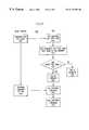
- FIG. 1A block diagram of a system of a base station communicating with a set of RF transponders (tags).
- FIG. 2A block diagram of a preferred RF tag
- FIG. 3An example of the most preferred memory layout of a tag having the tag memory partitioned into three memories.
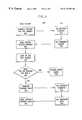
- FIG. 4A flow chart for a preferred method of using the tag type number.
- FIG. 5A flow chart for an alternative method of using the tag type code.
- FIG. 6A flow chart for an alternative method of using the tag type code.
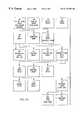
- FIG. 7A diagram of a hierarchical approach of software tag type memory mapping.
- FIG. 8A diagram of a preferred memory layout of a tag memory.
- the present inventionis a system of one or more base stations, (or a time sequenced series of base stations which will allow new ideas to be implemented as they occur and mature), each of which can communicate with a number of different types of communication devices.
- FIG. 1shows a system comprising a base station 100 comprising a base station computer 102 or other logic devices having a base station memory 104 and a base station receiver/transmitter 106 connected to a base station antenna 110 sending RF electromagnetic waves 120 to the tag antennas 130 and 140 of two tags 131 and 141 .
- the preferred embodimentsuse RF electromagnetic (EM) waves for communication between the tags 131 and 141 and the base station 100 .
- EMelectromagnetic
- tags sketched in FIG. 2which have a tag receiver/transmitter section 150 , a tag logic section 160 , and a read write tag memory section 170 which may be read and written by RF communication to and from the base station 100 .
- the base station 100sends RF power and information to the tag antenna 130 of tag 131 .
- the tag receiver/transmitter 150receives power from the RF energy 120 , and transmits this power to the tag logic section 160 and the tag memory section 170 .
- the tagmay be powered by a battery or other power source as known in the art.
- the tag receiver/transmitter section 150sends a low frequency modulation of the RF signal 120 to the tag logic section 160 .
- the tag logic section 160interprets the low frequency modulated signal and may write data to or read data from the tag memory 170 .
- the tag logic section 160may send data read from the tag memory to the tag receiver/transmitter section 150 , which modulates the reflectance of the tag antenna 130 and hence transmits information to the base station 100 .
- Each base stationmust be able to send information to and receive information from at least two tag types.
- Each base stationcould have the capability of communicating with at least two types of tags which use different physical means of communicating (e.g., different RF carrier frequencies, different polarization of the RF radiation), or different modulation methods (e.g., frequency modulation, amplitude modulation, or phase modulation).
- tags which communicate using the above mentioned differing physical meansare examples of preferred hardware types of tags.
- the base stations of the more preferred embodimentscommunicate with tag types which differ in hardware type only that the different tag types have different amounts of read/write memory and/or different functional capabilities such as locking and/or password capabilities and/or ability to obey different commands sent from the base station.
- commands which a particular tag of a specific tag type might, or might not, recognizeare an enable command and a disable command, where the base station commands a particular tag or all tags of a particular hardware type to enable or disable electronic equipment attached to the tag.
- Further examplesare the group select and group unselect commands, where particular tags or groups of tags having particular data in the tag memory are instructed to ready themselves for further communication or action or disable themselves from the further communication or action.
- each taghas a unique identifying number or code stored in the tag memory, (although this is not necessary for the invention) and a second number or code stored in the memory which may not be unique to the tag or to the associated object and which specifies the tag type.
- the tag type numberidentifies the layout of the information in the memory of the tag, (the software tag type), as well as hardware characteristics of the tag such as the amount of memory the tag holds and the command set recognized by the tag, (the hardware tag type).
- FIG. 3depicts an example of the most preferred memory layout 200 of a tag having the tag memory 170 partitioned into three memories.
- the first 8 bytes 210 of the tag memory layout 200specifies the unique identifying code of the tag
- the second 8 bytes 220 of the tag memory layout 200specifies the tag type
- the remainder 230 of the tag memory layout 200is used for other purposes.
- the remainder 230is shown as 8 bytes as an example, but the invention is not limited to the amount of memory 230 remaining. It is well within the scope of the invention to have 0 bytes of memory in the remainder 230 of the tag memory layout 200 .
- the tag type numberwould then specify that there is no memory remaining free in the tag after the unique tag identifying code 210 and the tag type 220 are written.
- the tag type identifying number 220be in the same place in the tag memory layout 200 for all tags in the system.
- the tag type identifying number or codeis located in the bytes 9 through 16 of the tag memory, but the exact location and the exact number of bytes or bits is not essential to the invention.
- the location of the tag type codeis decided by the tag, and the base station may ask for the tag type code by ‘name’ instead of asking for a particular set of bytes in a particular location.
- tags type code or other coded informationcould be “hard wired” in the physical layout of the chip as logic circuits and wiring. Such “hard wired” circuits are defined in this application as part of the tag memory.
- Other parts of the tag memorycould be codable and/or recodable memory elements such as EE-PROM memory elements or FRAM memory elements or ROM memory elements.
- the entire tag type codecould be used in communication between the tag and the base station, or just a part of the tag type code, as will be explained later.
- the remainder 230 of the tag memory layout 200 in the exampleis shown starting at byte 17, and in general the start location of the remainder 230 will be defined by defining the amount of memory taken by the unique tag identification number and the tag type code number. It is convenient to have the remainder 230 start at a fixed location in the preferred embodiments, since the remainder 230 can in general contain many different amounts of memory. The total amount of memory contained in the tag can also be determined from the tag type code.
- FIG. 3shows the memory organized in bytes which consist of eight bits, it is well within the scope of the invention to have the basic unit of memory other than one byte.
- datais transferred one byte at a time.
- tag functionincreases to transfer data 16 bits or 32 bits or indeed any number of bits at a time, and the memory organization would reflect the data handling unit size.
- the use of the specific word “byte” hereinmay be also read as any fixed number of bits as required by the system.
- a tagis associated with some object, thing, or person.
- the tagWhen the tag is associated with an object, there might be particular data fields which the tag would contain that are relevant to the object (e.g., a retail tag may contain a universal product code (UPC) and/or a Stock Keeping Unit number (SKU)).
- UPCuniversal product code
- SKUStock Keeping Unit number
- the tag typedetermines which information is stored on this tag, and where in the data in the tag memory the information is stored.
- the base station 100then reads the tag type number or code 220 , and on the basis of the tag type number or code 220 the base station can determine which information the tag contains and where in the tag memory layout 230 the information is stored.
- the data in the tag memory layout 230is an undifferentiated string of zeros and ones containing no information or confusing information, since the data in the memory 230 could be read in one way for one type of tag, and another way for a different type of tag.
- the base stationcan read and interpret the data in the tag memory and retrieve the information stored in the data.
- the base stationcan also write to the tags of the identified and selected tag type with a command to put a particular data set representing particular information in a particular location, and know that the data set represents the same information for each tag, and then when the data is read at a future time, the data will return the same information to the same or another base station.
- the base stationsends a command 405 to the tag to transmit the tag type number to the base station. (The most preferred command is that the tag transmits 8 bytes starting at byte 9 of the tag memory)
- the tagreceives the command at step 410 .
- the tagtransmits the tag type number to the base station 415 .
- the base stationreceives the tag type number from the tag in step 420 , and looks up the tag type number in the base station memory in step 425 . If the base station finds that the tag contains the desired information 430 , the base station sends a command in step 435 to the tag to transmit the data which has the required information in the tag memory to the base station.
- the base stationdirects the tag to transmit M bytes starting at memory location N, where M and N are integers determined by the base station lookup table.
- the tagreceives the command in step 440 , and transmits 445 the data requested.
- the base stationreceives the data in step 450 , and proceeds further with the use of the data. If the base station finds that the information required is not contained in the tag on the basis of the tag type number at step 430 , the base station may return an error signal 460 , or take other appropriate action. With these steps, the sequence of numbers in the data of the tag type memory are translated to information, for example, a UPC and a security code.
- a tag type codeis transmitted from the base station to the tag in step 505 .
- the tagreceives the tag type code.
- the tagcompares the tag type code transmitted from the base station with the tag type code stored in the tag memory. The tag logic makes a decision at step 520 whether the two numbers match. If the two numbers do not match 525 , the tag is disabled and does not transmit for the rest of the communication protocol, or until it is specifically ordered to transmit at a later time. If the numbers match, the tag is enabled 530 . The base station then knows which specific types of tags are enabled.
- the base stationsends a command 540 to transmit data in a particular location in the tag memory back to the base station or to write data to a particular location.
- the base stationknows that the particular data requested or sent is the particular information of interest on the basis of the lookup table.
- the tagreceives the command to transmit data or to write data at step 545 , and transmits the requested data to the base station or writes the transmitted data to the designated location in the tag memory in step 550 .
- the base stationreceives the requested information in step 560 .
- the tag typemay also be used in combination with other data in the tag memory to further select sub groups for communication.
- the tag type code and the other dataare sent from the base station to the tag, and the tag compares both the tag type code and the other data and responds only if the tag type code and the other data match. In some cases, only a subset of the tag type number may be sent for comparison purposes, as will be described later. As will be explained later, a single byte of the preferred 8 byte tag type number may ensure that a particular memory location has data such as a security code.
- a tag type codeis transmitted from the base station to the tag in step 605 .
- the tagreceives the tag type code.
- the tagcompares the tag type code transmitted from the base station with the tag type code stored in the tag memory.
- the tag logicmakes a decision at step 620 whether the two numbers match. If the two numbers do not match 625 , the tag is disabled and does not transmit or obey commands for the rest of the communication protocol, or until it is specifically ordered to transmit or “wake up” at a later time. If the numbers match, the tag is enabled 630 to obey commands from the base station. The base station then knows which specific types of tags are enabled.
- the base stationsends a command to do something to the tag in step 640 .
- the tagreceives the command in step 645 , and executes the command 650 .
- This sequenceavoids the problem that other tags will receive the command, not recognize the command, and try to communicate with the base station, thus interfering with the communications between the base station and the tags which do understand the command.
- One example of such a commandis that the command that the tag enable or disable attached equipment.
- a tagmay be independent of an object, and instead of describing an associated object, be used merely to store information which then can be retrieved by RF communications.
- the tag typewould still be used to determine the data fields on the tag as well as other tag characteristics. This use of such tags is also within the scope of the invention.
- the tag type number or code 220distinguishes between different hardware types as well as describes the layout of the tag memory.
- all tags made on the same manufacturing linehave the same physical layout and the same hardware tag type.
- tags with physically different layoutsare possible. They might have, for example, different antenna designs, different logic and memory circuits, different voltages necessary to run the tag, different packaging to withstand different environments, measurement circuits to measure temperature, humidity, biological activity and status, etc. and would in general have different hardware tag type numbers.
- the tagscould be connected to instruments with various sorts of measurement capabilities.
- Other hardware tag typesinclude types which require more or less power to run, or types which would signal when the power received was adequate for a write operation as distinguished from just reading the received power.
- the tag type number 220is 8 bytes, with the first two bytes reserved for a hardware tag type number, which allows for 65,536 different types of hardware configurations.
- the remaining 6 bytes of the tag type numberis a software tag type number, which allows for 2.8 ⁇ 10 4 different ways to lay out information in the tag memory.
- the systemmay employ one or more types of base stations which may employ different hardware and/or software to communicate with a plurality of types of tag.
- each base stationidentifies and communicates with at least some of the different tag types by “reading” the tag type number or some other characteristic such as the frequency emitted from the tag.
- the base station“looks up” the protocol for communicating with the tag using a “look up” table.
- the base stationneed only keep a much reduced set of numbers, i.e.
- a base stationwill have the protocol for communication for the tags produced or envisioned up to the time of introduction of the base station.
- the tag type numbers and protocols introduced after the introduction of a particular base station type and not planned for at the time of the base station programmingmust be introduced to existing base stations by reprogramming the base station memory or retrofitting the base station.
- the base stationcould return an error message stating that an “unknown” tag type was in the field.
- all present and future base stationswould have the ability to at least read the tag type numbers of all present and future tags.
- the two byte hardware type numberwould be not be able to be changed by RF communication means once the tag is released from the manufacturing line. While the hardware tag type number is described heretofore as being contained in the tag memory, the hardware tag type number could be contained as well in the tag hardware, ie hardwired in gates, in a state machine, or in microcode. While the hardware tag type contained in tag memory could be read by a normal tag read command, it could also be read through a special command, or the hardware tag type number could be returned as part of the tag identifier.
- the last 6 bytes of the 8 byte tag type number in the most preferred embodimentare reserved for the “software tag type number”, describing the software configuration of the tag, e.g., where the UPC is stored in the tag memory.
- the base station softwarecould then interpret the data in the tag memory by knowing the software type.
- the software tag typecould be changed by command from a base station if the tag memory mapping needed to change.
- the tagswould also have different software types, since the full memory maps would be different in the two tags (since one is larger).
- the memory in the first 16 bytes of memory layout 230could be mapped the same in both. This means that the mapping for a 32 byte tag could be a subset of the mapping of the 64 byte tag, and the tag type for the 16 byte tag could similarly be a subset of the tag type for the 64 byte tag.
- the same software type codecould be used for both, and the hardware type code would tell the base station to ignore the unavailable data.
- the software type of the tagcould be changed as its usage needs changed. For example, as a tagged object moved along the supply chain from manufacturer to distributor to retailer, the data needs of each party would change. The manufacturer may not care and not need to know whether the object were destined for a large retail store or a wholesale outlet, and could use the information bytes 230 on the tag for manufacturing details. The tag type would then reflect which manufacturing details were recorded and where they were stored in the tag memory. As the object and the associated tag passed from manufacturer to distributer, the distributer could erase those manufacturing details no longer needed, and change the tag type to signify the re-mapping of the freed memory.
- the retailercould erase those details which were not of interest, and change the tag type to signify the re-mapping of the freed memory.
- the retailercould store data relevant to his or her business, such as the date and price of the sale, whether there was a discount, the salesperson's identity, the store name, as well as warranty information.
- tags of a particular hardware tag typebe able to respond to an interrogation signal and a request for identification.
- This “group select” command capabilitymakes it possible to communicate with a particular tag or group of tags when more than one tag type is in range. Without the selection, communication could be difficult if tags of different types used different protocols to communicate the data contained in the tag memory. It would be as if each type of tag were ‘speaking their own language.’
- the base stationcan make use of the tag type to know which ‘language’ to use in the communication. It can select a group of tags based on their type and know they will all use the same communication protocol, for example.
- tagswith respect to their software type is very important. Without knowing where data fields reside in the tag memory it becomes impossible to know how to interpret the data being written to or read from a tag. A command to select a group of tags based on a particular software tag type will bring responses from only tags of that particular tag type. This means that data going to or coming from any tag in this selected group may then be interpreted according to the known memory map determined by that tag type.
- FIG. 8shows a memory layout where the tag carries a directory 810 of the information that it contains.
- the base stationsends a command to read or write a field having a name, and the tag looks up the name in the directory. If that field exists, the tag knows from the directory the location in the tag memory where the field is stored. The tag then retrieves the information stored in the field, and transmits the information to the base station, or the tag writes the data sent by the base station to the field. In general, the fact that the tag contains a directory will be reflected in the tag type number.
- Group selecting on a software tag typeenables commands to be more efficient. If one wishes to communicate with a group of tags all at once, with a single command, all those tags must be able to understand that command and respond appropriately. There are commands that can be effective and efficiently used to write data to many tags at once via broadcasts. However, in addition to a tag having to understand the command itself (which would be determined by the hardware tag type), the data field being broadcast must ‘find its way’ to the correct memory location on the tag. Since group selection of tags of a particular tag type insures that those selected tags have the same memory mapping, one can now safely broadcast the data to a particular memory location without addressing each tag individually with a particular (and perhaps different) destination memory location. Now instead of having to write a data field to many tags individually, on a tag by tag basis, you can do a broadcast write to all tags of that tag type without identifying the individual tags.
- group select and write broadcasting on tag typesconsider the checkout scenario in a retail setting.
- the retailerwants the customer to pay for the goods purchased, and then leave the store without those goods setting off the store alarm.
- group select on items of a certain software tag typee.g., ‘retail tag’
- the hardware type tagswhich recognizes the “write broadcast” command would also be selected.
- This commandis preferably a command to write a ‘1’ in a specific memory location.
- the software tag type ‘retail'guarantees a specific location in the memory layout 200 for the alarm flag.
- Group selecting on the tag typeis a critical element in enabling efficient writing via broadcasts to more than one tag at a time because it can assure that the data is going to be written to the correct location in memory.
- the second issueis a practical one relating to usage of the tag. It is quite likely that if a tag is to be used by many parties, there would be some data fields that would be common needs of them all, and some that would be distinctive. If each of the parties were to use their own software type, potentially a very mixed collection of software types could appear together at a later point in the processing chain. As an example, imagine a retailer who obtains products from many different manufacturers. If all of them used different software types, by the time items came to the checkout counter, you would be likely to have many more than one type present. This would imply that the usefulness of a write broadcasting capability is drastically reduced, since a given data field may be located in different memory locations in the tags of different software types.
- the software tag type numberis a series of bytes (in the case of the preferred embodiments 6 bytes), in which each successive byte represents a level in a hierarchy of classifications. Each level in the hierarchy defines a fixed memory location for data fields common to everything below in the hierarchy. So, in the example above, if everyone from manufacturing, through distribution, down to the retailer, needs to use the security field or alarm flag, this field mapping would be determined high in the hierarchy, at a node that would be represented by a byte in the software tag type.
- a second consequence of the hierarchical structure use of software tag typeis that fewer lookup tables need be stored by any given customer. If software types were just random numbers specifying a mapping of the full memory of the tag, this would require a different table for each different mapping, in spite of the fact that there would be much overlap in data fields needed by many tag types.
- the hierarchygives structure to the sets of tables, and only tables related to the relevant branch in the hierarchy need be stored and maintained. In addition, tables could be such that they only represent the data fields that are new additions for their node in the hierarchy. So, a table for manufacturing-distribution-retail may only contain entries for the memory locations of the data fields ‘security’ and ‘UPC’.
- a base station that reads retail tagsneed only contain entries added on by being ‘retail’, such as ‘price paid’ (among others) for example.
- the tableswould be joined, to find the mappings relevant for any given node in the hierarchy, precluding the need for a larger set of tables mapping the whole memory.
- This approachalso is more extensible, since as new fields are introduced, (perhaps as tag memory increases), a much smaller subset of tables needs to be updated or replaced than if each table mapped memory exhaustively.
- FIG. 7gives an example 700 of the hierarchical approach to software type and memory mapping.
- the node in the hierarchywould be reflected as a value of a byte in the software tag type.
- all manufacturing, distribution, and retail tagsmay require a UPC code.
- the memory location of the UPCwould be the same across all tags used in that general industry.
- the fact that the tag is a manufacturing-distribution-retail tag’is encoded in the 1 st or ‘lowest order’ byte of the software type.
- the number 1has been assigned to the value of the first byte of the software type code for manufacturing-distribution-retail type tags 702 .
- a general manufacturing-distribution-retail type tagwould have a tag type number 000001.
- the common data across all tags of this software typeare shown in the example as the manufacture date, the UPC number, and a security code. Other data which might be included might be the manufacturers identification code.
- the second byte in the example of FIG. 7serves to break down the manufacturing 720 , distribution 722 , or retail 724 , into the component parts by assigning the numbers 1, 2 and 3 respectively to the second byte of the software tag type number.
- the location of expiration dateis not guaranteed simply by knowing the tag is a manufacturing-distribution-retail tag on the basis of the first byte of the tag type code.
- a base stationmay order all tags with tag types having 11231 in the lowest order bytes of the tag type number to turn themselves on, and all others to remain silent. Then the base station may order the active tags to compare a number in a particular memory location (representing the expiration date) with a number sent by the base station (today's date), and to respond if the numbers match. If a tag responds, the object (for example a cut of meat in the meat cooler) which will go out of date today may be retrieved and marked down for quick sale.
- ‘perishable’is a category that some sub-branch of the distribution industry may need to know about.
- the distribution industrywould also agree on the location in tag memory of the expiration date, and presumably the expiration date would be in the same place in the tag memory for the all the distribution tag types, and the expiration date for the ‘retail’ tags might be in a different place in the tag memory than it is in the ‘distribution’ tags.
- the problem with any hierarchical approachis that there may be conflicts in classification. Some activities will fit into more than one category, or be some hybrid of several categories. The goal is to percolate upward data fields needed by everyone below that point in the hierarchy and try to reduce the duplication of fields in related branches of the hierarchy.
- the distributormay need to read the memory and reformat it to fit with the distribution structure, if it is different from the manufacturing structure. For example, at the point of manufacture of a shirt, the manufacturer will not be likely to know or care if this shirt is to be delivered to a specialty store or a department store, so ultimate store destination may not be a field used in the manufacturer's tag processing. The manufacturer may use the same memory elements that the distributor will later use for another purpose. As the tag is passed through to the distribution center, the tag may be updated as the destination is determined.
- tags 712 used for person trackingfit this description. These applications may be cross industry, and hence not fit very well within the hierarchical structure organized by industry. These types of applications, such as person tracking, are closely tied to the ‘object’, in this case, person. The same might be said for something like a ‘pallet’ 714 , or ‘carton’ 716 tags. It is proposed that they be high level nodes—on a par with the top level industry breakdown—determined by the lowest order byte (for example) in the software tag type. Medical 706 , finance 708 , and government 710 are also shown at this level as examples.
- a “person” tag 712would be one choice equivalent to the manufacturing-distribution-retailing tags 702 as shown by FIG. 7 .
- the industriesmay have their own particular needs. Pursuing the example of ‘person tracking’, at the ‘person’ level, you may have a need for name fields, that would be common across industries. However, the retail industry 730 may be a child of that person node, and it may need a ‘store ID’. Lower levels in the hierarchy such as “customer” 752 , and “preferred customer” 770 are also shown on FIG. 7 . Other levels in the hierarchy shown by FIG.
- FIG. 7are the second level manufacture tags 726 and distribution tags 728 equivalent to the retail tag 730 of the person 712 mode. Possible examples of classifications relating to the tag types having a 1 in the lowest order byte are also shown on FIG. 7 to show other examples of the hierarchical structure.
- the inventionis not limited to the above examples.
- the inventorsanticipate many equivalent ways to accomplish the hierarchical approach to ordering the software tag types.
- which particular byte of the tag type code is higher in the hierarchyis not important, as long as the order of the hierarchy is accepted by the participants.
Landscapes
- Engineering & Computer Science (AREA)
- Physics & Mathematics (AREA)
- General Physics & Mathematics (AREA)
- Health & Medical Sciences (AREA)
- Toxicology (AREA)
- Artificial Intelligence (AREA)
- Computer Vision & Pattern Recognition (AREA)
- Theoretical Computer Science (AREA)
- Computer Networks & Wireless Communication (AREA)
- Electromagnetism (AREA)
- General Health & Medical Sciences (AREA)
- Mobile Radio Communication Systems (AREA)
Abstract
Description
Claims (49)
Priority Applications (1)
| Application Number | Priority Date | Filing Date | Title |
|---|---|---|---|
| US08/811,989US6172596B1 (en) | 1994-09-09 | 1997-03-05 | System method and apparatus for identifying and communicating with a plurality of types of radio frequency communication devices |
Applications Claiming Priority (2)
| Application Number | Priority Date | Filing Date | Title |
|---|---|---|---|
| US08/303,965US5673037A (en) | 1994-09-09 | 1994-09-09 | System and method for radio frequency tag group select |
| US08/811,989US6172596B1 (en) | 1994-09-09 | 1997-03-05 | System method and apparatus for identifying and communicating with a plurality of types of radio frequency communication devices |
Related Parent Applications (1)
| Application Number | Title | Priority Date | Filing Date |
|---|---|---|---|
| US08/303,965Continuation-In-PartUS5673037A (en) | 1994-09-09 | 1994-09-09 | System and method for radio frequency tag group select |
Publications (1)
| Publication Number | Publication Date |
|---|---|
| US6172596B1true US6172596B1 (en) | 2001-01-09 |
Family
ID=46203077
Family Applications (1)
| Application Number | Title | Priority Date | Filing Date |
|---|---|---|---|
| US08/811,989Expired - LifetimeUS6172596B1 (en) | 1994-09-09 | 1997-03-05 | System method and apparatus for identifying and communicating with a plurality of types of radio frequency communication devices |
Country Status (1)
| Country | Link |
|---|---|
| US (1) | US6172596B1 (en) |
Cited By (97)
| Publication number | Priority date | Publication date | Assignee | Title |
|---|---|---|---|---|
| US20020016739A1 (en)* | 1999-09-21 | 2002-02-07 | Fujitsu Limited | System and method for managing expiration-dated products utilizing an electronic receipt |
| US20020093426A1 (en)* | 1995-10-11 | 2002-07-18 | Jackson Miles R. | Enabling/enhancing a feature of an electronic device using radio frequency identification technology |
| US20020165731A1 (en)* | 2001-03-09 | 2002-11-07 | Sentinel Wireless, Llc | System and method for performing object association at a tradeshow using a location tracking system |
| US6480100B1 (en)* | 2001-03-09 | 2002-11-12 | Sat Corporation | Radio frequency identification tag formatting method |
| US6483426B1 (en)* | 1997-12-10 | 2002-11-19 | Pagnol Frederic | Method of identifying a plurality of transponders, analysis apparatus and a transponder for implementing such a method |
| WO2003012720A1 (en)* | 2001-07-30 | 2003-02-13 | Savi Technology | Method and system for managing supply chain networks |
| US20030033280A1 (en)* | 2001-05-18 | 2003-02-13 | Van Den Hamer Peter | Self-descriptive data tag |
| US6557760B2 (en)* | 2001-03-30 | 2003-05-06 | Ncr Corporation | System and method of managing expired products |
| WO2003052673A1 (en)* | 2001-12-17 | 2003-06-26 | Koninklijke Philips Electronics N.V. | Communication station for inventorizing transponders by means of selectable memory areas of the transponders |
| US20030132853A1 (en)* | 2002-01-11 | 2003-07-17 | Ebert Peter S. | Exchange of article-based information between multiple enterprises |
| US6608551B1 (en)* | 1999-09-13 | 2003-08-19 | Intermec Ip Corp | Low-cost radio replacement utilizing RFID technology |
| US6617962B1 (en)* | 2000-01-06 | 2003-09-09 | Samsys Technologies Inc. | System for multi-standard RFID tags |
| US20030171984A1 (en)* | 2002-03-06 | 2003-09-11 | Wodka Joseph F. | Customization of promotional material through use of programmable radio frequency identification technology |
| US20030174099A1 (en)* | 2002-01-09 | 2003-09-18 | Westvaco Corporation | Intelligent station using multiple RF antennae and inventory control system and method incorporating same |
| US6633227B1 (en)* | 1997-08-08 | 2003-10-14 | Robert Bosch Gmbh | Method for operating a remote control, and remote control |
| US6760019B1 (en)* | 2000-06-01 | 2004-07-06 | Sun Microsystems, Inc. | Methods and apparatus for facilitating the sharing of computer graphics operations |
| US20050015548A1 (en)* | 2002-09-23 | 2005-01-20 | Siemens Aktiengesellschaft | Method for transmitting data, particularly over an air interface |
| US20050099268A1 (en)* | 2003-11-12 | 2005-05-12 | Ari Juels | Radio frequency identification system with privacy policy implementation based on device classification |
| US20050099307A1 (en)* | 2003-11-06 | 2005-05-12 | International Business Machines Corporation | Radio frequency identification aiding the visually impaired with sound skins |
| WO2005027022A3 (en)* | 2003-09-11 | 2005-06-09 | Impinj Inc | Secure two-way rfid communications |
| US20050121526A1 (en)* | 2003-12-09 | 2005-06-09 | Intelleflex Corporation | Battery activation circuit |
| US20050140502A1 (en)* | 2003-12-26 | 2005-06-30 | Hitachi, Ltd. | Method for setting product number in ROM type RFID chip and method, apparatus and system for managing product implementation |
| US20050149350A1 (en)* | 2003-12-24 | 2005-07-07 | Kerr Roger S. | Patient information management system and method |
| EP1345183A3 (en)* | 2002-03-07 | 2005-08-17 | Hitachi, Ltd. | RFID tag and related determination and management |
| US20050179521A1 (en)* | 2004-02-12 | 2005-08-18 | Intermec Ip Corp. | Frequency hopping method for RFID tag |
| US20050242196A1 (en)* | 2001-05-31 | 2005-11-03 | Alien Technology Corp. | Integrated circuits with persistent data storage |
| US6972682B2 (en) | 2002-01-18 | 2005-12-06 | Georgia Tech Research Corporation | Monitoring and tracking of assets by utilizing wireless communications |
| EP1610232A1 (en)* | 2004-06-21 | 2005-12-28 | Sap Ag | Accessing data tags using database queries |
| US20060052055A1 (en)* | 2004-09-08 | 2006-03-09 | Nokia Corporation | Electronic near field communication enabled multifunctional device and method of its operation |
| US20060087407A1 (en)* | 2004-10-27 | 2006-04-27 | Intelleflex Corporation | Master tags |
| US20060103506A1 (en)* | 1998-06-02 | 2006-05-18 | Rodgers James L | Object identification system with adaptive transceivers and methods of operation |
| US20060109086A1 (en)* | 2002-08-28 | 2006-05-25 | Koninklijke Philips Electronics N.V. | Method of inventorying transponders by means of a communication station |
| US20060176177A1 (en)* | 2005-01-26 | 2006-08-10 | Rf Technologies, Inc. | Mobile locator system and method |
| US20060187045A1 (en)* | 2005-01-26 | 2006-08-24 | Rf Technologies, Inc. | Mobile locator system and method with wander management |
| US20060202033A1 (en)* | 2005-03-03 | 2006-09-14 | Campero Richard J | Apparatus for and method of using an intelligent network and RFID signal router |
| WO2006104354A1 (en) | 2005-03-30 | 2006-10-05 | Samsung Electronics Co., Ltd. | Rf-id tag reading system for using password and method thereof |
| US20060255131A1 (en)* | 2005-05-11 | 2006-11-16 | Intelleflex Corporation | Smart tag activation |
| US20070004381A1 (en)* | 2005-06-30 | 2007-01-04 | Larson Thane M | Authenticating maintenance access to an electronics unit via wireless communication |
| US20070001850A1 (en)* | 2005-06-30 | 2007-01-04 | Malone Christopher G | Wireless temperature monitoring for an electronics system |
| US20070001807A1 (en)* | 2005-06-30 | 2007-01-04 | Malone Christopher G | Wireless monitoring for an electronics system |
| US20070001837A1 (en)* | 2005-06-30 | 2007-01-04 | Larson Thane M | Wireless monitoring of component compatibility in an electronics system |
| US20070018794A1 (en)* | 2005-07-20 | 2007-01-25 | Intelleflex Corporation | Selective RF device activation |
| US20070052525A1 (en)* | 2005-03-11 | 2007-03-08 | Chenghao Quan | RFID system and method for protecting information |
| US20070141983A1 (en)* | 2005-12-15 | 2007-06-21 | Intelleflex Corporation | Clock-free activation circuit |
| US7248168B2 (en) | 2004-06-21 | 2007-07-24 | Sap Aktiengesellschaft | Accessing data tag information using database queries |
| US20070198720A1 (en)* | 2006-02-17 | 2007-08-23 | Neteffect, Inc. | Method and apparatus for a interfacing device drivers to a single multi-function adapter |
| US20070273507A1 (en)* | 2005-04-22 | 2007-11-29 | Jonathan Burchell | Apparatus and method for monitoring and communicating data associated with a product |
| US20080047972A1 (en)* | 2001-06-01 | 2008-02-28 | Bartholomew Julie R | Point-of-sale body powder dispensing system |
| US20080106417A1 (en)* | 2006-10-14 | 2008-05-08 | Bradley Gerald W | Method and middleware for standards agnostic transaction processing |
| US20080106386A1 (en)* | 2006-10-17 | 2008-05-08 | International Business Machines Corporation | Methods, systems, and computer program products for providing mutual authentication for radio frequency identification (rfid) security |
| US7377445B1 (en) | 2001-05-31 | 2008-05-27 | Alien Technology Corporation | Integrated circuits with persistent data storage |
| US20080191882A1 (en)* | 2007-02-14 | 2008-08-14 | Nec (China) Co., Ltd. | Radio frequency identification system and method |
| US20080284570A1 (en)* | 2005-04-25 | 2008-11-20 | Seung Hyup Ryoo | Reader Control System |
| US20090052557A1 (en)* | 2007-08-24 | 2009-02-26 | Intelligent Design Systems, Inc. | Data encoder system |
| US20090115575A1 (en)* | 2007-11-01 | 2009-05-07 | Shao-Ming Lee | Apparatus, system for storing data, and method for accessing data directory |
| US20090153329A1 (en)* | 2007-12-17 | 2009-06-18 | Electronics And Telecommunications Research Institute | Method of generating activation code for radio frequency identification tag |
| US7624769B2 (en) | 2004-11-08 | 2009-12-01 | Cosmetic Technologies, L.L.C. | Automated customized cosmetic dispenser |
| US20090315717A1 (en)* | 2005-06-16 | 2009-12-24 | Koninklijke Philips Electronics N.V. | Tracking rfid objects with integrated communication link |
| US20090322482A1 (en)* | 2008-06-30 | 2009-12-31 | Frederick Schuessler | Delimited Read Command for Efficient Data Access from Radio Frequency Identification (RFID) Tags |
| US20090322479A1 (en)* | 2007-05-23 | 2009-12-31 | Sony Corporation | Communications system and communications apparatus |
| US20100066510A1 (en)* | 2008-09-12 | 2010-03-18 | Mstar Semiconductor, Inc. | Control Method for RFID Tag and RFID System Thereof |
| US20100085157A1 (en)* | 2006-09-14 | 2010-04-08 | Electronics And Telecommunications Research Institute | Method for providing service using rfid tag identifier in rfid system and apparatus thereof |
| US20100134258A1 (en)* | 2008-12-01 | 2010-06-03 | Mstar Semiconductor, Inc. | Method and System of Utilizing RFID Tags for Jointly Processing Task |
| USD626949S1 (en) | 2008-02-20 | 2010-11-09 | Vocollect Healthcare Systems, Inc. | Body-worn mobile device |
| US20110050400A1 (en)* | 2009-08-25 | 2011-03-03 | Sensormatic Electronics Corporation | Rfid portal system with rfid tags having various read ranges |
| US20110148599A1 (en)* | 2009-12-21 | 2011-06-23 | Electronics And Telecommunications Research Institute | Rfid reader, rfid tag, and method of recognizing plurality of rfid tags |
| US20110148570A1 (en)* | 2009-12-21 | 2011-06-23 | Christian Weidinger | Configuration RFID Circuit |
| USD643013S1 (en) | 2010-08-20 | 2011-08-09 | Vocollect Healthcare Systems, Inc. | Body-worn mobile device |
| USD643400S1 (en) | 2010-08-19 | 2011-08-16 | Vocollect Healthcare Systems, Inc. | Body-worn mobile device |
| US8061604B1 (en)* | 2003-02-13 | 2011-11-22 | Sap Ag | System and method of master data management using RFID technology |
| US8128422B2 (en) | 2002-06-27 | 2012-03-06 | Vocollect, Inc. | Voice-directed portable terminals for wireless communication systems |
| US8134451B1 (en)* | 2007-05-31 | 2012-03-13 | Impinj, Inc. | RFID tag chips and tags capable of backscattering more codes and methods |
| US8141596B2 (en) | 2001-09-24 | 2012-03-27 | Cosmetic Technologies Llc | Apparatus and method for custom cosmetic dispensing |
| CN102842154A (en)* | 2012-08-31 | 2012-12-26 | 北京邮电大学 | Power grid equipment polling device and polling method based on RFID (radio frequency identification) |
| US8386261B2 (en) | 2008-11-14 | 2013-02-26 | Vocollect Healthcare Systems, Inc. | Training/coaching system for a voice-enabled work environment |
| US8390431B1 (en) | 2007-05-31 | 2013-03-05 | Impinj, Inc. | RFID tags that backscatter more codes |
| WO2013041860A1 (en)* | 2011-09-21 | 2013-03-28 | Friendly Technologies Ltd. | Inventorying transponders |
| US20130105568A1 (en)* | 2011-11-01 | 2013-05-02 | Codonics, Inc. | Adaptable information extraction and labeling method and system |
| US8573263B2 (en) | 2001-09-24 | 2013-11-05 | Cosmetic Technologies, Llc | Apparatus and method for custom cosmetic dispensing |
| US8659397B2 (en) | 2010-07-22 | 2014-02-25 | Vocollect, Inc. | Method and system for correctly identifying specific RFID tags |
| US20140117081A1 (en)* | 2011-11-01 | 2014-05-01 | Codonics, Inc. | Adaptable information extraction and labeling method and system |
| US8730044B2 (en) | 2002-01-09 | 2014-05-20 | Tyco Fire & Security Gmbh | Method of assigning and deducing the location of articles detected by multiple RFID antennae |
| US20140139320A1 (en)* | 2012-11-16 | 2014-05-22 | Tyco Electronics Uk Ltd. | Method and system for performing a single localized read transaction in which multiple rfid tags are read |
| US20140139324A1 (en)* | 2012-11-16 | 2014-05-22 | Toshiba Tec Kabushiki Kaisha | Radio tag communication apparatus, radio tag communication system, and radio tag search program |
| US8941469B1 (en)* | 2010-06-14 | 2015-01-27 | Impinj, Inc. | RFID tag authentication with public-key cryptography |
| US9031872B1 (en) | 2013-03-12 | 2015-05-12 | Target Brands, Inc. | Digital sign with incorrectly stocked item identification |
| US9710754B2 (en) | 2012-10-09 | 2017-07-18 | Infratab, Inc. | Inference electronic shelf life dating system for perishables |
| US9729363B2 (en) | 2013-09-09 | 2017-08-08 | Crfs Limited | Frequency discriminator |
| US9727879B2 (en)* | 2011-03-30 | 2017-08-08 | Nokia Technologies Oy | Method and apparatus for providing tag-based content installation |
| US9946904B2 (en) | 2004-04-27 | 2018-04-17 | Infratab, Inc. | Apparatus and method for monitoring and communicating data associated with a product |
| WO2019046336A1 (en)* | 2017-08-28 | 2019-03-07 | Shoof Technologies, Inc. | Collaborative sensor network |
| EP3594888A1 (en)* | 2018-07-13 | 2020-01-15 | Motorola Mobility LLC | Storing a user address in a transceiver identification field for identification tags on smart objects |
| US10628723B2 (en) | 2018-07-10 | 2020-04-21 | Datamax-O'neil Corporation | Methods, systems, and apparatuses for encoding a radio frequency identification (RFID) inlay |
| WO2021007244A1 (en)* | 2019-07-11 | 2021-01-14 | Zebra Technologies Corporation | Scanning devices and methods to constrain radio frequency identification (rfid) signals within a physical location |
| CN114091486A (en)* | 2021-10-18 | 2022-02-25 | 青岛海尔科技有限公司 | An NFC chip data interaction method, device, middleware and electronic device |
| US11412835B2 (en) | 2015-06-08 | 2022-08-16 | Cosmetic Technologies, L.L.C. | Automated delivery system of a cosmetic sample |
| US12169752B1 (en)* | 2011-01-17 | 2024-12-17 | Impinj, Inc. | Enhanced RFID tag authentication |
Citations (5)
| Publication number | Priority date | Publication date | Assignee | Title |
|---|---|---|---|---|
| US4827395A (en)* | 1983-04-21 | 1989-05-02 | Intelli-Tech Corporation | Manufacturing monitoring and control systems |
| US5008661A (en)* | 1985-09-27 | 1991-04-16 | Raj Phani K | Electronic remote chemical identification system |
| US5214410A (en)* | 1989-07-10 | 1993-05-25 | Csir | Location of objects |
| US5481519A (en)* | 1990-10-03 | 1996-01-02 | Canon Kabushiki Kaisha | Method for recording, reproducing and managing file data on a recording medium |
| US5887176A (en)* | 1996-06-28 | 1999-03-23 | Randtec, Inc. | Method and system for remote monitoring and tracking of inventory |
- 1997
- 1997-03-05USUS08/811,989patent/US6172596B1/ennot_activeExpired - Lifetime
Patent Citations (5)
| Publication number | Priority date | Publication date | Assignee | Title |
|---|---|---|---|---|
| US4827395A (en)* | 1983-04-21 | 1989-05-02 | Intelli-Tech Corporation | Manufacturing monitoring and control systems |
| US5008661A (en)* | 1985-09-27 | 1991-04-16 | Raj Phani K | Electronic remote chemical identification system |
| US5214410A (en)* | 1989-07-10 | 1993-05-25 | Csir | Location of objects |
| US5481519A (en)* | 1990-10-03 | 1996-01-02 | Canon Kabushiki Kaisha | Method for recording, reproducing and managing file data on a recording medium |
| US5887176A (en)* | 1996-06-28 | 1999-03-23 | Randtec, Inc. | Method and system for remote monitoring and tracking of inventory |
Cited By (217)
| Publication number | Priority date | Publication date | Assignee | Title |
|---|---|---|---|---|
| US7057492B2 (en) | 1995-10-11 | 2006-06-06 | Motorola, Inc. | Enabling/enhancing a feature of an electronic device using radio frequency identification technology |
| US20020093426A1 (en)* | 1995-10-11 | 2002-07-18 | Jackson Miles R. | Enabling/enhancing a feature of an electronic device using radio frequency identification technology |
| US6633227B1 (en)* | 1997-08-08 | 2003-10-14 | Robert Bosch Gmbh | Method for operating a remote control, and remote control |
| US6483426B1 (en)* | 1997-12-10 | 2002-11-19 | Pagnol Frederic | Method of identifying a plurality of transponders, analysis apparatus and a transponder for implementing such a method |
| US20060103506A1 (en)* | 1998-06-02 | 2006-05-18 | Rodgers James L | Object identification system with adaptive transceivers and methods of operation |
| US7633378B2 (en)* | 1998-06-02 | 2009-12-15 | Rf Code, Inc. | Object identification system with adaptive transceivers and methods of operation |
| US6608551B1 (en)* | 1999-09-13 | 2003-08-19 | Intermec Ip Corp | Low-cost radio replacement utilizing RFID technology |
| US7050991B2 (en)* | 1999-09-21 | 2006-05-23 | Fujitsu Limited | System and method for managing expiration-dated products utilizing an electronic receipt |
| US20020016739A1 (en)* | 1999-09-21 | 2002-02-07 | Fujitsu Limited | System and method for managing expiration-dated products utilizing an electronic receipt |
| US6617962B1 (en)* | 2000-01-06 | 2003-09-09 | Samsys Technologies Inc. | System for multi-standard RFID tags |
| US6760019B1 (en)* | 2000-06-01 | 2004-07-06 | Sun Microsystems, Inc. | Methods and apparatus for facilitating the sharing of computer graphics operations |
| US8165928B2 (en) | 2000-12-07 | 2012-04-24 | Savi Technology, Inc. | Managing events within supply chain networks |
| US20040015418A1 (en)* | 2000-12-07 | 2004-01-22 | Dooley John J. | Method and system for managing supply chain networks |
| US6480100B1 (en)* | 2001-03-09 | 2002-11-12 | Sat Corporation | Radio frequency identification tag formatting method |
| US20020165731A1 (en)* | 2001-03-09 | 2002-11-07 | Sentinel Wireless, Llc | System and method for performing object association at a tradeshow using a location tracking system |
| US6557760B2 (en)* | 2001-03-30 | 2003-05-06 | Ncr Corporation | System and method of managing expired products |
| US9619742B2 (en)* | 2001-05-18 | 2017-04-11 | Nxp B.V. | Self-descriptive data tag |
| US20030033280A1 (en)* | 2001-05-18 | 2003-02-13 | Van Den Hamer Peter | Self-descriptive data tag |
| US7737825B1 (en)* | 2001-05-31 | 2010-06-15 | Alien Technology Corporation | Integrated circuits with persistent data storage |
| US8464957B2 (en) | 2001-05-31 | 2013-06-18 | Alien Technology Corporation | Integrated circuits with persistent data storage |
| US8936201B2 (en) | 2001-05-31 | 2015-01-20 | Alien Technology, Llc | Integrated circuits with persistent data storage |
| US7377445B1 (en) | 2001-05-31 | 2008-05-27 | Alien Technology Corporation | Integrated circuits with persistent data storage |
| US9406012B2 (en) | 2001-05-31 | 2016-08-02 | Ruizhang Technology Limited Company | Integrated circuits with persistent data storage |
| US20050242196A1 (en)* | 2001-05-31 | 2005-11-03 | Alien Technology Corp. | Integrated circuits with persistent data storage |
| US8056818B2 (en) | 2001-05-31 | 2011-11-15 | Alien Technology Corporation | Integrated circuits with persistent data storage |
| US7364084B2 (en) | 2001-05-31 | 2008-04-29 | Alien Technology Corporation | Integrated circuits with persistent data storage |
| US20080047972A1 (en)* | 2001-06-01 | 2008-02-28 | Bartholomew Julie R | Point-of-sale body powder dispensing system |
| US8636173B2 (en) | 2001-06-01 | 2014-01-28 | Cosmetic Technologies, L.L.C. | Point-of-sale body powder dispensing system |
| WO2003012720A1 (en)* | 2001-07-30 | 2003-02-13 | Savi Technology | Method and system for managing supply chain networks |
| US8141596B2 (en) | 2001-09-24 | 2012-03-27 | Cosmetic Technologies Llc | Apparatus and method for custom cosmetic dispensing |
| US8573263B2 (en) | 2001-09-24 | 2013-11-05 | Cosmetic Technologies, Llc | Apparatus and method for custom cosmetic dispensing |
| WO2003052673A1 (en)* | 2001-12-17 | 2003-06-26 | Koninklijke Philips Electronics N.V. | Communication station for inventorizing transponders by means of selectable memory areas of the transponders |
| US20060238307A1 (en)* | 2002-01-09 | 2006-10-26 | Bauer Donald G | Intelligent station using multiple RF antennae and inventory control system and method incorporating same |
| US8730044B2 (en) | 2002-01-09 | 2014-05-20 | Tyco Fire & Security Gmbh | Method of assigning and deducing the location of articles detected by multiple RFID antennae |
| US7084769B2 (en) | 2002-01-09 | 2006-08-01 | Vue Technology, Inc. | Intelligent station using multiple RF antennae and inventory control system and method incorporating same |
| US20030174099A1 (en)* | 2002-01-09 | 2003-09-18 | Westvaco Corporation | Intelligent station using multiple RF antennae and inventory control system and method incorporating same |
| US20060232382A1 (en)* | 2002-01-09 | 2006-10-19 | Bauer Donald G | Intelligent station using multiple RF antennae and inventory control system and method incorporating same |
| US20030132853A1 (en)* | 2002-01-11 | 2003-07-17 | Ebert Peter S. | Exchange of article-based information between multiple enterprises |
| US6941184B2 (en)* | 2002-01-11 | 2005-09-06 | Sap Aktiengesellschaft | Exchange of article-based information between multiple enterprises |
| US6972682B2 (en) | 2002-01-18 | 2005-12-06 | Georgia Tech Research Corporation | Monitoring and tracking of assets by utilizing wireless communications |
| US20030171984A1 (en)* | 2002-03-06 | 2003-09-11 | Wodka Joseph F. | Customization of promotional material through use of programmable radio frequency identification technology |
| WO2003077454A3 (en)* | 2002-03-06 | 2004-03-11 | Motorola Inc | Customization of promotional material through use of programmable radio frequency identification technology |
| CN100437632C (en)* | 2002-03-07 | 2008-11-26 | 株式会社日立制作所 | RFID tag and related determination and management |
| EP1345183A3 (en)* | 2002-03-07 | 2005-08-17 | Hitachi, Ltd. | RFID tag and related determination and management |
| US8128422B2 (en) | 2002-06-27 | 2012-03-06 | Vocollect, Inc. | Voice-directed portable terminals for wireless communication systems |
| US20060109086A1 (en)* | 2002-08-28 | 2006-05-25 | Koninklijke Philips Electronics N.V. | Method of inventorying transponders by means of a communication station |
| US7834742B2 (en)* | 2002-08-28 | 2010-11-16 | Nxp B.V. | Method of inventorying transponders by means of a communication station |
| US20050015548A1 (en)* | 2002-09-23 | 2005-01-20 | Siemens Aktiengesellschaft | Method for transmitting data, particularly over an air interface |
| US8061604B1 (en)* | 2003-02-13 | 2011-11-22 | Sap Ag | System and method of master data management using RFID technology |
| US9691053B1 (en) | 2003-02-13 | 2017-06-27 | Sap Se | System and method of master data management |
| WO2005027022A3 (en)* | 2003-09-11 | 2005-06-09 | Impinj Inc | Secure two-way rfid communications |
| US20070177738A1 (en)* | 2003-09-11 | 2007-08-02 | Impinj, Inc., A Delaware Corporation | Secure two-way RFID communications |
| US6992592B2 (en) | 2003-11-06 | 2006-01-31 | International Business Machines Corporation | Radio frequency identification aiding the visually impaired with sound skins |
| US20050099307A1 (en)* | 2003-11-06 | 2005-05-12 | International Business Machines Corporation | Radio frequency identification aiding the visually impaired with sound skins |
| US20050099268A1 (en)* | 2003-11-12 | 2005-05-12 | Ari Juels | Radio frequency identification system with privacy policy implementation based on device classification |
| US7298243B2 (en)* | 2003-11-12 | 2007-11-20 | Rsa Security Inc. | Radio frequency identification system with privacy policy implementation based on device classification |
| US7612652B2 (en) | 2003-12-09 | 2009-11-03 | Intelleflex Corporation | Battery activation circuit |
| US20050121526A1 (en)* | 2003-12-09 | 2005-06-09 | Intelleflex Corporation | Battery activation circuit |
| WO2005057688A2 (en) | 2003-12-09 | 2005-06-23 | Intelleflex Corporation | Battery activation circuit |
| EP1692883A4 (en)* | 2003-12-09 | 2008-06-04 | Intelleflex Corp | Battery activation circuit |
| US20050149350A1 (en)* | 2003-12-24 | 2005-07-07 | Kerr Roger S. | Patient information management system and method |
| US20050140502A1 (en)* | 2003-12-26 | 2005-06-30 | Hitachi, Ltd. | Method for setting product number in ROM type RFID chip and method, apparatus and system for managing product implementation |
| US7378941B2 (en)* | 2003-12-26 | 2008-05-27 | Hitachi, Ltd. | Method for setting product number in ROM type RFID chip and method, apparatus and system for managing product implementation |
| US20050179521A1 (en)* | 2004-02-12 | 2005-08-18 | Intermec Ip Corp. | Frequency hopping method for RFID tag |
| US9946904B2 (en) | 2004-04-27 | 2018-04-17 | Infratab, Inc. | Apparatus and method for monitoring and communicating data associated with a product |
| US7248168B2 (en) | 2004-06-21 | 2007-07-24 | Sap Aktiengesellschaft | Accessing data tag information using database queries |
| EP1610232A1 (en)* | 2004-06-21 | 2005-12-28 | Sap Ag | Accessing data tags using database queries |
| US8564408B2 (en) | 2004-09-08 | 2013-10-22 | Nokia Corporation | Electronic Near Field Communication enabled multifunctional device and method of its operation |
| US20100026454A1 (en)* | 2004-09-08 | 2010-02-04 | Nokia Corporation | Electronic near field communication enabled multifunctional device and method of its operation |
| US20060052055A1 (en)* | 2004-09-08 | 2006-03-09 | Nokia Corporation | Electronic near field communication enabled multifunctional device and method of its operation |
| US7375616B2 (en)* | 2004-09-08 | 2008-05-20 | Nokia Corporation | Electronic near field communication enabled multifunctional device and method of its operation |
| WO2006049636A3 (en)* | 2004-10-27 | 2007-10-04 | Intelleflex Corp | Master tags |
| US20060087407A1 (en)* | 2004-10-27 | 2006-04-27 | Intelleflex Corporation | Master tags |
| CN101147124B (en)* | 2004-10-27 | 2011-08-31 | 因特莱弗莱克斯公司 | A method and system for creating a radio frequency identification tag hierarchy |
| US7646300B2 (en) | 2004-10-27 | 2010-01-12 | Intelleflex Corporation | Master tags |
| US9984526B2 (en) | 2004-11-08 | 2018-05-29 | Cosmetic Technologies, L.L.C. | Automated customized cosmetic dispenser |
| US8608371B2 (en) | 2004-11-08 | 2013-12-17 | Cosmetic Technologies, Llc | Automated customized cosmetic dispenser |
| EP2343692A1 (en) | 2004-11-08 | 2011-07-13 | Bartholomew, Julie R. | Automated customized cosmetic dispenser |
| US9691213B2 (en) | 2004-11-08 | 2017-06-27 | Cosmetic Technologies, L.L.C. | Automated customized cosmetic dispenser |
| US20100116843A1 (en)* | 2004-11-08 | 2010-05-13 | Cosmetic Technologies. L.L.C. | Automated customized cosmetic dispenser |
| US8186872B2 (en) | 2004-11-08 | 2012-05-29 | Cosmetic Technologies | Automated customized cosmetic dispenser |
| US7624769B2 (en) | 2004-11-08 | 2009-12-01 | Cosmetic Technologies, L.L.C. | Automated customized cosmetic dispenser |
| US7274294B2 (en) | 2005-01-26 | 2007-09-25 | Rf Technologies, Inc. | Mobile locator system and method |
| US7365645B2 (en) | 2005-01-26 | 2008-04-29 | Rf Technologies, Inc. | Mobile locator system and method with wander management |
| US20060187045A1 (en)* | 2005-01-26 | 2006-08-24 | Rf Technologies, Inc. | Mobile locator system and method with wander management |
| US20060176177A1 (en)* | 2005-01-26 | 2006-08-10 | Rf Technologies, Inc. | Mobile locator system and method |
| US20060220875A1 (en)* | 2005-03-03 | 2006-10-05 | Campero Richard J | Apparatus for and method of using an intelligent network and RFID signal router |
| US20060220876A1 (en)* | 2005-03-03 | 2006-10-05 | Campero Richard J | Apparatus for and method of using an intelligent network and RFID signal router |
| US20060220874A1 (en)* | 2005-03-03 | 2006-10-05 | Campero Richard J | Apparatus for and method of using an intelligent network and RFID signal router |
| US7750812B2 (en) | 2005-03-03 | 2010-07-06 | Sensormatic Electronics, Llc. | Apparatus for and method of using an intelligent network and RFID signal router |
| US20060220873A1 (en)* | 2005-03-03 | 2006-10-05 | Campero Richard J | Apparatus for and method of using an intelligent network and RFID signal router |
| US7656858B2 (en) | 2005-03-03 | 2010-02-02 | Sensormatic Electronics, Llc. | Apparatus for and method of using an intelligent network and RFID signal router |
| US20060220862A1 (en)* | 2005-03-03 | 2006-10-05 | Campero Richard J | Apparatus for and method of using an intelligent network and RFID signal router |
| US20060202033A1 (en)* | 2005-03-03 | 2006-09-14 | Campero Richard J | Apparatus for and method of using an intelligent network and RFID signal router |
| US20070052525A1 (en)* | 2005-03-11 | 2007-03-08 | Chenghao Quan | RFID system and method for protecting information |
| WO2006104354A1 (en) | 2005-03-30 | 2006-10-05 | Samsung Electronics Co., Ltd. | Rf-id tag reading system for using password and method thereof |
| EP1864248A4 (en)* | 2005-03-30 | 2008-08-27 | Samsung Electronics Co Ltd | RF-ID LABEL READING SYSTEM USING PASSWORDS AND METHOD THEREFOR |
| US7764183B2 (en)* | 2005-04-22 | 2010-07-27 | Infratab, Inc. | Apparatus and method for monitoring and communicating data associated with a product |
| US20070273507A1 (en)* | 2005-04-22 | 2007-11-29 | Jonathan Burchell | Apparatus and method for monitoring and communicating data associated with a product |
| US20090051493A1 (en)* | 2005-04-25 | 2009-02-26 | Kongsberg Automotive As | Reader control system |
| US9679172B2 (en) | 2005-04-25 | 2017-06-13 | Lg Electronics Inc. | Reader control system |
| US20100045445A1 (en)* | 2005-04-25 | 2010-02-25 | Seung Hyup Ryoo | Reader control system |
| US8604913B2 (en) | 2005-04-25 | 2013-12-10 | Lg Electronics Inc. | Reader control system |
| US8598989B2 (en) | 2005-04-25 | 2013-12-03 | Lg Electronics Inc. | Reader control system |
| US8653948B2 (en) | 2005-04-25 | 2014-02-18 | Lg Electronics Inc. | Reader control system |
| US8665066B2 (en) | 2005-04-25 | 2014-03-04 | Lg Electronics Inc. | Reader control system |
| US20090219143A1 (en)* | 2005-04-25 | 2009-09-03 | Seung Hyup Ryoo | Reader control system |
| US8698604B2 (en) | 2005-04-25 | 2014-04-15 | Lg Electronics Inc. | Reader control system |
| US8508343B2 (en) | 2005-04-25 | 2013-08-13 | Lg Electronics Inc. | Reader control system |
| US8749355B2 (en) | 2005-04-25 | 2014-06-10 | Lg Electronics Inc. | Reader control system |
| US9672395B2 (en) | 2005-04-25 | 2017-06-06 | Lg Electronics Inc. | Reader control system |
| US8482389B2 (en) | 2005-04-25 | 2013-07-09 | Lg Electronics Inc. | Reader control system |
| US8624712B2 (en) | 2005-04-25 | 2014-01-07 | Lg Electronics Inc. | Reader control system |
| US8115604B2 (en) | 2005-04-25 | 2012-02-14 | Lg Electronics Inc. | Reader control system |
| US20080316019A1 (en)* | 2005-04-25 | 2008-12-25 | Seung Hyup Ryoo | Reader Control System |
| US20110072318A1 (en)* | 2005-04-25 | 2011-03-24 | Seung Hyup Ryoo | Reader control system |
| US20110063084A1 (en)* | 2005-04-25 | 2011-03-17 | Seung Hyup Ryoo | Reader control system |
| US8378790B2 (en) | 2005-04-25 | 2013-02-19 | Lg Electronics Inc. | Reader control system |
| US20110068908A1 (en)* | 2005-04-25 | 2011-03-24 | Seung Hyup Ryoo | Reader control system |
| US20110068907A1 (en)* | 2005-04-25 | 2011-03-24 | Seung Hyup Ryoo | Reader control system |
| US20080284570A1 (en)* | 2005-04-25 | 2008-11-20 | Seung Hyup Ryoo | Reader Control System |
| US8115595B2 (en)* | 2005-04-25 | 2012-02-14 | Lg Electronics Inc. | Reader control system |
| US20110156881A1 (en)* | 2005-04-25 | 2011-06-30 | Seung Hyup Ryoo | Reader control system |
| US20110156882A1 (en)* | 2005-04-25 | 2011-06-30 | Seung Hyup Ryoo | Reader control system |
| US20060255131A1 (en)* | 2005-05-11 | 2006-11-16 | Intelleflex Corporation | Smart tag activation |
| US7604178B2 (en) | 2005-05-11 | 2009-10-20 | Intelleflex Corporation | Smart tag activation |
| US9035772B2 (en)* | 2005-06-16 | 2015-05-19 | Koninklijke Philips N.V. | Tracking RFID objects with integrated communication link |
| US20150256969A1 (en)* | 2005-06-16 | 2015-09-10 | Koninklijke Philips N.V. | Tracking rfid objects with integrated communication link |
| US9801011B2 (en)* | 2005-06-16 | 2017-10-24 | Koninklijke Philips N.V. | Tracking RFID objects with integrated communication link |
| US20090315717A1 (en)* | 2005-06-16 | 2009-12-24 | Koninklijke Philips Electronics N.V. | Tracking rfid objects with integrated communication link |
| US20070001807A1 (en)* | 2005-06-30 | 2007-01-04 | Malone Christopher G | Wireless monitoring for an electronics system |
| US7400252B2 (en) | 2005-06-30 | 2008-07-15 | Hewlett-Packard Development Company, L.P. | Wireless monitoring of component compatibility in an electronics system |
| US20070004381A1 (en)* | 2005-06-30 | 2007-01-04 | Larson Thane M | Authenticating maintenance access to an electronics unit via wireless communication |
| US20070001850A1 (en)* | 2005-06-30 | 2007-01-04 | Malone Christopher G | Wireless temperature monitoring for an electronics system |
| US7336153B2 (en) | 2005-06-30 | 2008-02-26 | Hewlett-Packard Development Company, L.P. | Wireless temperature monitoring for an electronics system |
| US7737847B2 (en) | 2005-06-30 | 2010-06-15 | Hewlett-Packard Development Company, L.P. | Wireless monitoring for an electronics system |
| US20070001837A1 (en)* | 2005-06-30 | 2007-01-04 | Larson Thane M | Wireless monitoring of component compatibility in an electronics system |
| US7607014B2 (en) | 2005-06-30 | 2009-10-20 | Hewlett-Packard Development Company, L.P. | Authenticating maintenance access to an electronics unit via wireless communication |
| US20070018794A1 (en)* | 2005-07-20 | 2007-01-25 | Intelleflex Corporation | Selective RF device activation |
| US8248211B2 (en) | 2005-07-20 | 2012-08-21 | Intelleflex Corporation | Selective RF device activation |
| US8674809B2 (en) | 2005-07-20 | 2014-03-18 | Intelleflex Corporation | Selective RF device activation |
| US7592917B2 (en)* | 2005-11-03 | 2009-09-22 | Electronics And Telecommunications Research Institute | RFID system and method for protecting information |
| US8548098B2 (en) | 2005-12-15 | 2013-10-01 | Intelleflex Corporation | Clock-free activation circuit |
| US20070141983A1 (en)* | 2005-12-15 | 2007-06-21 | Intelleflex Corporation | Clock-free activation circuit |
| US20070198720A1 (en)* | 2006-02-17 | 2007-08-23 | Neteffect, Inc. | Method and apparatus for a interfacing device drivers to a single multi-function adapter |
| US20100085157A1 (en)* | 2006-09-14 | 2010-04-08 | Electronics And Telecommunications Research Institute | Method for providing service using rfid tag identifier in rfid system and apparatus thereof |
| US7737848B2 (en)* | 2006-10-14 | 2010-06-15 | Rfideaworks Corporation | Method and middleware for standards agnostic transaction processing |
| US20080106417A1 (en)* | 2006-10-14 | 2008-05-08 | Bradley Gerald W | Method and middleware for standards agnostic transaction processing |
| US20080106386A1 (en)* | 2006-10-17 | 2008-05-08 | International Business Machines Corporation | Methods, systems, and computer program products for providing mutual authentication for radio frequency identification (rfid) security |
| US7791451B2 (en)* | 2006-10-17 | 2010-09-07 | International Business Machines Corporation | Methods, systems, and computer program products for providing mutual authentication for radio frequency identification (RFID) security |
| US20080191882A1 (en)* | 2007-02-14 | 2008-08-14 | Nec (China) Co., Ltd. | Radio frequency identification system and method |
| US10497194B2 (en) | 2007-05-23 | 2019-12-03 | Sony Corporation | Communications system and communications apparatus |
| US11017622B2 (en) | 2007-05-23 | 2021-05-25 | Sony Corporation | Communications system and communications apparatus |
| US9792743B2 (en) | 2007-05-23 | 2017-10-17 | Sony Corporation | Communications system and communications apparatus |
| US20090322479A1 (en)* | 2007-05-23 | 2009-12-31 | Sony Corporation | Communications system and communications apparatus |
| US8598985B2 (en)* | 2007-05-23 | 2013-12-03 | Sony Corporation | Communications system and communications apparatus |
| US8174367B1 (en)* | 2007-05-31 | 2012-05-08 | Impinj, Inc. | Causing RFID tags to backscatter more codes |
| US8134451B1 (en)* | 2007-05-31 | 2012-03-13 | Impinj, Inc. | RFID tag chips and tags capable of backscattering more codes and methods |
| US8390431B1 (en) | 2007-05-31 | 2013-03-05 | Impinj, Inc. | RFID tags that backscatter more codes |
| US7528744B2 (en)* | 2007-08-24 | 2009-05-05 | Intelligent Design Systems, Inc. | Data encoder system |
| US7932842B2 (en)* | 2007-08-24 | 2011-04-26 | Intelligent Design Systems, Inc. | Method of encoding data |
| US20090219178A1 (en)* | 2007-08-24 | 2009-09-03 | Intelligent Design Systems, Inc. | Method of encoding data |
| US20090052557A1 (en)* | 2007-08-24 | 2009-02-26 | Intelligent Design Systems, Inc. | Data encoder system |
| US20090115575A1 (en)* | 2007-11-01 | 2009-05-07 | Shao-Ming Lee | Apparatus, system for storing data, and method for accessing data directory |
| US20090153329A1 (en)* | 2007-12-17 | 2009-06-18 | Electronics And Telecommunications Research Institute | Method of generating activation code for radio frequency identification tag |
| US8519827B2 (en)* | 2007-12-17 | 2013-08-27 | Electronics And Telecommunications Research Institute | Method of generating activation code for radio frequency identification tag |
| USD626949S1 (en) | 2008-02-20 | 2010-11-09 | Vocollect Healthcare Systems, Inc. | Body-worn mobile device |
| US20090322482A1 (en)* | 2008-06-30 | 2009-12-31 | Frederick Schuessler | Delimited Read Command for Efficient Data Access from Radio Frequency Identification (RFID) Tags |
| US8598990B2 (en)* | 2008-06-30 | 2013-12-03 | Symbol Technologies, Inc. | Delimited read command for efficient data access from radio frequency identification (RFID) tags |
| US8674811B2 (en)* | 2008-09-12 | 2014-03-18 | Mstar Semiconductor, Inc. | Control method for RFID tag and RFID system thereof |
| US20100066510A1 (en)* | 2008-09-12 | 2010-03-18 | Mstar Semiconductor, Inc. | Control Method for RFID Tag and RFID System Thereof |
| US8386261B2 (en) | 2008-11-14 | 2013-02-26 | Vocollect Healthcare Systems, Inc. | Training/coaching system for a voice-enabled work environment |
| US8400275B2 (en)* | 2008-12-01 | 2013-03-19 | Mstar Semiconductor, Inc. | Method and system of utilizing RFID tags for jointly processing task |
| US20100134258A1 (en)* | 2008-12-01 | 2010-06-03 | Mstar Semiconductor, Inc. | Method and System of Utilizing RFID Tags for Jointly Processing Task |
| US8717145B2 (en) | 2009-08-25 | 2014-05-06 | Tyco Fire & Security Services GmbH | RFID portal system with RFID tags having various read ranges |
| US20110050400A1 (en)* | 2009-08-25 | 2011-03-03 | Sensormatic Electronics Corporation | Rfid portal system with rfid tags having various read ranges |
| CN102483796A (en)* | 2009-08-25 | 2012-05-30 | 传感电子有限责任公司 | RFID gate system configured with RFID tags having various read ranges |
| WO2011028237A1 (en)* | 2009-08-25 | 2011-03-10 | Sensormatic Electronics, LLC | Rfid portal system with rfid tags having various read ranges |
| CN102483796B (en)* | 2009-08-25 | 2015-07-01 | 传感电子有限责任公司 | Rfid portal system with rfid tags having various read ranges |
| US20110148570A1 (en)* | 2009-12-21 | 2011-06-23 | Christian Weidinger | Configuration RFID Circuit |
| US9679173B2 (en) | 2009-12-21 | 2017-06-13 | Nxp B.V. | Apparatuses and methods using command sets specific for controlling the operation of a type of the RFID transponder to which the command sets are transmitted |
| US20110148599A1 (en)* | 2009-12-21 | 2011-06-23 | Electronics And Telecommunications Research Institute | Rfid reader, rfid tag, and method of recognizing plurality of rfid tags |
| US8941469B1 (en)* | 2010-06-14 | 2015-01-27 | Impinj, Inc. | RFID tag authentication with public-key cryptography |
| US9111283B1 (en)* | 2010-06-14 | 2015-08-18 | Impinj, Inc. | RFID tag authentication with public-key cryptography |
| US8659397B2 (en) | 2010-07-22 | 2014-02-25 | Vocollect, Inc. | Method and system for correctly identifying specific RFID tags |
| US9449205B2 (en) | 2010-07-22 | 2016-09-20 | Vocollect, Inc. | Method and system for correctly identifying specific RFID tags |
| US10108824B2 (en) | 2010-07-22 | 2018-10-23 | Vocollect, Inc. | Method and system for correctly identifying specific RFID tags |
| US8933791B2 (en) | 2010-07-22 | 2015-01-13 | Vocollect, Inc. | Method and system for correctly identifying specific RFID tags |
| USD643400S1 (en) | 2010-08-19 | 2011-08-16 | Vocollect Healthcare Systems, Inc. | Body-worn mobile device |
| USD643013S1 (en) | 2010-08-20 | 2011-08-09 | Vocollect Healthcare Systems, Inc. | Body-worn mobile device |
| US12169752B1 (en)* | 2011-01-17 | 2024-12-17 | Impinj, Inc. | Enhanced RFID tag authentication |
| US9727879B2 (en)* | 2011-03-30 | 2017-08-08 | Nokia Technologies Oy | Method and apparatus for providing tag-based content installation |
| CN104054089A (en)* | 2011-09-21 | 2014-09-17 | 方便技术有限公司 | inventory answering machine |
| WO2013041860A1 (en)* | 2011-09-21 | 2013-03-28 | Friendly Technologies Ltd. | Inventorying transponders |
| US20140117081A1 (en)* | 2011-11-01 | 2014-05-01 | Codonics, Inc. | Adaptable information extraction and labeling method and system |
| US20130105568A1 (en)* | 2011-11-01 | 2013-05-02 | Codonics, Inc. | Adaptable information extraction and labeling method and system |
| US9697331B2 (en)* | 2011-11-01 | 2017-07-04 | Codonics, Inc. | Adaptable information extraction and labeling method and system |
| CN102842154A (en)* | 2012-08-31 | 2012-12-26 | 北京邮电大学 | Power grid equipment polling device and polling method based on RFID (radio frequency identification) |
| CN102842154B (en)* | 2012-08-31 | 2015-11-18 | 北京邮电大学 | Based on grid equipment inspection device and the method for inspecting of RFID |
| US9710754B2 (en) | 2012-10-09 | 2017-07-18 | Infratab, Inc. | Inference electronic shelf life dating system for perishables |
| US9384375B2 (en)* | 2012-11-16 | 2016-07-05 | Toshiba Tec Kabushiki Kaisha | Radio tag communication apparatus, radio tag communication system, and a non-transitory computer-readable recording medium |
| US20140139324A1 (en)* | 2012-11-16 | 2014-05-22 | Toshiba Tec Kabushiki Kaisha | Radio tag communication apparatus, radio tag communication system, and radio tag search program |
| US20140139320A1 (en)* | 2012-11-16 | 2014-05-22 | Tyco Electronics Uk Ltd. | Method and system for performing a single localized read transaction in which multiple rfid tags are read |
| US9858454B2 (en) | 2012-11-16 | 2018-01-02 | Toshiba Tec Kabushiki Kaisha | Method and a radio tag communication apparatus |
| US10205287B2 (en) | 2012-11-16 | 2019-02-12 | Commscope Connectivity Uk Limited | Method and system for performing a single localized read transaction in which multiple RFID tags are read |
| US9722367B2 (en)* | 2012-11-16 | 2017-08-01 | Commscope Connectivity Uk Limited | Method and system for performing a single localized read transaction in which multiple RFID tags are read |
| US9031872B1 (en) | 2013-03-12 | 2015-05-12 | Target Brands, Inc. | Digital sign with incorrectly stocked item identification |
| US9729363B2 (en) | 2013-09-09 | 2017-08-08 | Crfs Limited | Frequency discriminator |
| US11412835B2 (en) | 2015-06-08 | 2022-08-16 | Cosmetic Technologies, L.L.C. | Automated delivery system of a cosmetic sample |
| WO2019046336A1 (en)* | 2017-08-28 | 2019-03-07 | Shoof Technologies, Inc. | Collaborative sensor network |
| US10313447B2 (en) | 2017-08-28 | 2019-06-04 | Shoof Technologies, Inc. | Collaborative sensor network |
| US10956800B2 (en) | 2018-07-10 | 2021-03-23 | Datamax-O'neil Corporation | Methods, systems, and apparatuses for encoding a radio frequency identification (RFID) inlay |
| US10628723B2 (en) | 2018-07-10 | 2020-04-21 | Datamax-O'neil Corporation | Methods, systems, and apparatuses for encoding a radio frequency identification (RFID) inlay |
| EP3594888A1 (en)* | 2018-07-13 | 2020-01-15 | Motorola Mobility LLC | Storing a user address in a transceiver identification field for identification tags on smart objects |
| WO2021007244A1 (en)* | 2019-07-11 | 2021-01-14 | Zebra Technologies Corporation | Scanning devices and methods to constrain radio frequency identification (rfid) signals within a physical location |
| CN114091486A (en)* | 2021-10-18 | 2022-02-25 | 青岛海尔科技有限公司 | An NFC chip data interaction method, device, middleware and electronic device |
| CN114091486B (en)* | 2021-10-18 | 2024-03-22 | 青岛海尔科技有限公司 | NFC chip data interaction method and device, middleware and electronic equipment |
Similar Documents
| Publication | Publication Date | Title |
|---|---|---|
| US6172596B1 (en) | System method and apparatus for identifying and communicating with a plurality of types of radio frequency communication devices | |
| US7872582B1 (en) | RFID tag chips and tags with alternative memory lock bits and methods | |
| EP2471021B1 (en) | Rfid portal system with rfid tags having various read ranges | |
| US7173518B2 (en) | Method and apparatus for efficiently querying and identifying multiple items on a communication channel | |
| US7737823B2 (en) | Method for efficiently querying and identifying multiple items on a communication channel | |
| US7286043B2 (en) | System and method for inventorying multiple remote objects | |
| US5673037A (en) | System and method for radio frequency tag group select | |
| US7002451B2 (en) | Package location system | |
| US9405941B2 (en) | Simultaneous programming of selected tags | |
| US7145458B2 (en) | Non-contact IC tag system | |
| KR20060020730A (en) | Product identification tag and product management method using radio frequency communication | |
| KR100600571B1 (en) | Product identification tag and product management method using radio frequency communication | |
| US20240281634A1 (en) | Device and Method for Multiple Identity Tags Coupled to a Single Antenna or Single Antenna Array | |
| Miller | RFID: What’s it all about? | |
| HK1189979A (en) | Simultaneous programming of selected tags | |
| Patel et al. | Next generation of auto-ID: applying RFID technology | |
| Kumar et al. | RFID Technology for Identification, Security and Document Handling in Library | |
| HK1189979B (en) | Simultaneous programming of selected tags |
Legal Events
| Date | Code | Title | Description |
|---|---|---|---|
| AS | Assignment | Owner name:IBM CORPORATION, NEW YORK Free format text:ASSIGNMENT OF ASSIGNORS INTEREST;ASSIGNORS:CESAR, CHRISTIAN L.;COFINO, THOMAS A.;GOLDMAN, KENNETH A.;AND OTHERS;REEL/FRAME:008457/0041;SIGNING DATES FROM 19970217 TO 19970228 | |
| AS | Assignment | Owner name:UNOVA, INC., CALIFORNIA Free format text:ASSIGNMENT OF ASSIGNORS INTEREST;ASSIGNOR:INTERNATIONAL BUSINESS MACHINES CORP.;REEL/FRAME:009670/0450 Effective date:19971218 | |
| AS | Assignment | Owner name:INTERMEC IP CORP., A CORPORATION OF DELAWARE, CALI Free format text:ASSIGNMENT OF ASSIGNORS INTEREST;ASSIGNOR:UNOVA, INC., A CORPORATION OF DELAWARE;REEL/FRAME:009764/0534 Effective date:19990205 | |
| STCF | Information on status: patent grant | Free format text:PATENTED CASE | |
| FEPP | Fee payment procedure | Free format text:PAYOR NUMBER ASSIGNED (ORIGINAL EVENT CODE: ASPN); ENTITY STATUS OF PATENT OWNER: LARGE ENTITY | |
| FPAY | Fee payment | Year of fee payment:4 | |
| AS | Assignment | Owner name:KEYBANK NATIONAL ASSOCIATION, OHIO Free format text:SECURITY AGREEMENT;ASSIGNOR:INTERMEC IP CORP.;REEL/FRAME:016059/0047 Effective date:20040930 | |
| AS | Assignment | Owner name:INTERMEC IP CORP., WASHINGTON Free format text:RELEASE OF SECURITY INTEREST AT REEL/FRAME NO. 16059/0047;ASSIGNOR:KEYBANK NATIONAL ASSOCIATION;REEL/FRAME:019910/0215 Effective date:20070927 | |
| FPAY | Fee payment | Year of fee payment:8 | |
| REMI | Maintenance fee reminder mailed | ||
| FEPP | Fee payment procedure | Free format text:PAYOR NUMBER ASSIGNED (ORIGINAL EVENT CODE: ASPN); ENTITY STATUS OF PATENT OWNER: LARGE ENTITY Free format text:PAYER NUMBER DE-ASSIGNED (ORIGINAL EVENT CODE: RMPN); ENTITY STATUS OF PATENT OWNER: LARGE ENTITY | |
| FPAY | Fee payment | Year of fee payment:12 |