US6171574B1 - Method of linking membrane purification of hydrogen to its generation by steam reforming of a methanol-like fuel - Google Patents
Method of linking membrane purification of hydrogen to its generation by steam reforming of a methanol-like fuelDownload PDFInfo
- Publication number
- US6171574B1 US6171574B1US08/719,385US71938596AUS6171574B1US 6171574 B1US6171574 B1US 6171574B1US 71938596 AUS71938596 AUS 71938596AUS 6171574 B1US6171574 B1US 6171574B1
- Authority
- US
- United States
- Prior art keywords
- hydrogen
- membrane
- palladium
- methanol
- reforming
- Prior art date
- Legal status (The legal status is an assumption and is not a legal conclusion. Google has not performed a legal analysis and makes no representation as to the accuracy of the status listed.)
- Expired - Fee Related
Links
- 229910052739hydrogenInorganic materials0.000titleclaimsabstractdescription146
- 239000001257hydrogenSubstances0.000titleclaimsabstractdescription146
- UFHFLCQGNIYNRP-UHFFFAOYSA-NHydrogenChemical compound[H][H]UFHFLCQGNIYNRP-UHFFFAOYSA-N0.000titleclaimsabstractdescription131
- 239000012528membraneSubstances0.000titleclaimsabstractdescription124
- 238000000034methodMethods0.000titleclaimsabstractdescription29
- 238000000629steam reformingMethods0.000titleclaimsabstractdescription11
- 238000000746purificationMethods0.000titleclaimsdescription6
- 239000000446fuelSubstances0.000titleabstractdescription16
- OKKJLVBELUTLKV-UHFFFAOYSA-NMethanolChemical compoundOCOKKJLVBELUTLKV-UHFFFAOYSA-N0.000claimsabstractdescription165
- KDLHZDBZIXYQEI-UHFFFAOYSA-NPalladiumChemical group[Pd]KDLHZDBZIXYQEI-UHFFFAOYSA-N0.000claimsabstractdescription129
- 229910052763palladiumInorganic materials0.000claimsabstractdescription53
- 150000002431hydrogenChemical class0.000claimsabstractdescription19
- OKTJSMMVPCPJKN-UHFFFAOYSA-NCarbonChemical compound[C]OKTJSMMVPCPJKN-UHFFFAOYSA-N0.000claimsabstractdescription8
- 229910052799carbonInorganic materials0.000claimsabstractdescription8
- 239000012466permeateSubstances0.000claimsabstractdescription7
- 230000001737promoting effectEffects0.000claimsabstractdescription3
- 229910002091carbon monoxideInorganic materials0.000claimsdescription49
- CURLTUGMZLYLDI-UHFFFAOYSA-NCarbon dioxideChemical compoundO=C=OCURLTUGMZLYLDI-UHFFFAOYSA-N0.000claimsdescription45
- UGFAIRIUMAVXCW-UHFFFAOYSA-NCarbon monoxideChemical compound[O+]#[C-]UGFAIRIUMAVXCW-UHFFFAOYSA-N0.000claimsdescription43
- 239000003054catalystSubstances0.000claimsdescription33
- 238000002407reformingMethods0.000claimsdescription25
- 229910001252Pd alloyInorganic materials0.000claimsdescription22
- 229910002092carbon dioxideInorganic materials0.000claimsdescription18
- 239000010949copperSubstances0.000claimsdescription17
- 230000000607poisoning effectEffects0.000claimsdescription16
- RYGMFSIKBFXOCR-UHFFFAOYSA-NCopperChemical group[Cu]RYGMFSIKBFXOCR-UHFFFAOYSA-N0.000claimsdescription15
- 230000003197catalytic effectEffects0.000claimsdescription15
- 229910052802copperInorganic materials0.000claimsdescription15
- 231100000572poisoningToxicity0.000claimsdescription15
- 238000011065in-situ storageMethods0.000claimsdescription11
- 239000001569carbon dioxideSubstances0.000claimsdescription10
- 230000003647oxidationEffects0.000claimsdescription9
- 238000007254oxidation reactionMethods0.000claimsdescription9
- 230000008569processEffects0.000claimsdescription9
- 229910000881Cu alloyInorganic materials0.000claimsdescription8
- 239000010953base metalSubstances0.000claimsdescription8
- 229910052751metalInorganic materials0.000claimsdescription7
- 239000002184metalSubstances0.000claimsdescription7
- 230000007704transitionEffects0.000claimsdescription6
- QVGXLLKOCUKJST-UHFFFAOYSA-Natomic oxygenChemical compound[O]QVGXLLKOCUKJST-UHFFFAOYSA-N0.000claimsdescription5
- 239000001301oxygenSubstances0.000claimsdescription4
- 229910052760oxygenInorganic materials0.000claimsdescription4
- 238000006243chemical reactionMethods0.000description37
- 230000004907fluxEffects0.000description26
- 239000000376reactantSubstances0.000description17
- 239000000203mixtureSubstances0.000description15
- 208000005374PoisoningDiseases0.000description13
- 239000007789gasSubstances0.000description12
- 239000000047productSubstances0.000description12
- 229910052709silverInorganic materials0.000description11
- BQCADISMDOOEFD-UHFFFAOYSA-NSilverChemical compound[Ag]BQCADISMDOOEFD-UHFFFAOYSA-N0.000description10
- VNWKTOKETHGBQD-UHFFFAOYSA-NmethaneChemical compoundCVNWKTOKETHGBQD-UHFFFAOYSA-N0.000description10
- 239000004332silverSubstances0.000description10
- 229910001316Ag alloyInorganic materials0.000description9
- 239000010935stainless steelSubstances0.000description9
- 229910001220stainless steelInorganic materials0.000description9
- XLYOFNOQVPJJNP-UHFFFAOYSA-NwaterSubstancesOXLYOFNOQVPJJNP-UHFFFAOYSA-N0.000description9
- 229910045601alloyInorganic materials0.000description8
- 239000000956alloySubstances0.000description8
- 238000011144upstream manufacturingMethods0.000description8
- 239000011521glassSubstances0.000description7
- PXHVJJICTQNCMI-UHFFFAOYSA-NNickelChemical compound[Ni]PXHVJJICTQNCMI-UHFFFAOYSA-N0.000description6
- 230000002708enhancing effectEffects0.000description6
- 238000012552reviewMethods0.000description6
- 208000001408Carbon monoxide poisoningDiseases0.000description5
- 230000000694effectsEffects0.000description5
- 239000011888foilSubstances0.000description5
- 238000010438heat treatmentMethods0.000description5
- 239000006200vaporizerSubstances0.000description5
- 230000007423decreaseEffects0.000description4
- 238000009792diffusion processMethods0.000description4
- 238000002474experimental methodMethods0.000description4
- 238000004519manufacturing processMethods0.000description4
- 238000006057reforming reactionMethods0.000description4
- 229910052707rutheniumInorganic materials0.000description4
- 229910000929Ru alloyInorganic materials0.000description3
- KJTLSVCANCCWHF-UHFFFAOYSA-NRutheniumChemical compound[Ru]KJTLSVCANCCWHF-UHFFFAOYSA-N0.000description3
- 230000015572biosynthetic processEffects0.000description3
- 229910002090carbon oxideInorganic materials0.000description3
- 238000001193catalytic steam reformingMethods0.000description3
- 238000001651catalytic steam reforming of methanolMethods0.000description3
- 238000006356dehydrogenation reactionMethods0.000description3
- 239000007788liquidSubstances0.000description3
- 239000003345natural gasSubstances0.000description3
- 229910052759nickelInorganic materials0.000description3
- BASFCYQUMIYNBI-UHFFFAOYSA-NplatinumSubstances[Pt]BASFCYQUMIYNBI-UHFFFAOYSA-N0.000description3
- 230000008016vaporizationEffects0.000description3
- XKRFYHLGVUSROY-UHFFFAOYSA-NArgonChemical compound[Ar]XKRFYHLGVUSROY-UHFFFAOYSA-N0.000description2
- XEEYBQQBJWHFJM-UHFFFAOYSA-NIronChemical compound[Fe]XEEYBQQBJWHFJM-UHFFFAOYSA-N0.000description2
- ATUOYWHBWRKTHZ-UHFFFAOYSA-NPropaneChemical compoundCCCATUOYWHBWRKTHZ-UHFFFAOYSA-N0.000description2
- 230000004913activationEffects0.000description2
- 230000008901benefitEffects0.000description2
- 238000006555catalytic reactionMethods0.000description2
- 238000003889chemical engineeringMethods0.000description2
- 239000003245coalSubstances0.000description2
- -1coal) or of methaneChemical compound0.000description2
- 230000001351cycling effectEffects0.000description2
- 238000005202decontaminationMethods0.000description2
- 230000003588decontaminative effectEffects0.000description2
- 230000003247decreasing effectEffects0.000description2
- 238000005516engineering processMethods0.000description2
- 239000011152fibreglassSubstances0.000description2
- 238000002309gasificationMethods0.000description2
- 229930195733hydrocarbonNatural products0.000description2
- 150000002430hydrocarbonsChemical class0.000description2
- 238000005984hydrogenation reactionMethods0.000description2
- 230000000977initiatory effectEffects0.000description2
- 238000009413insulationMethods0.000description2
- 150000002739metalsChemical class0.000description2
- 239000002245particleSubstances0.000description2
- 229910052697platinumInorganic materials0.000description2
- 238000011084recoveryMethods0.000description2
- 230000008961swellingEffects0.000description2
- 238000012360testing methodMethods0.000description2
- 229910052723transition metalInorganic materials0.000description2
- 150000003624transition metalsChemical class0.000description2
- 238000009834vaporizationMethods0.000description2
- 229910000897Babbitt (metal)Inorganic materials0.000description1
- 239000004215Carbon black (E152)Substances0.000description1
- QPLDLSVMHZLSFG-UHFFFAOYSA-NCopper oxideChemical compound[Cu]=OQPLDLSVMHZLSFG-UHFFFAOYSA-N0.000description1
- 239000005751Copper oxideSubstances0.000description1
- 229910000570CupronickelInorganic materials0.000description1
- OTMSDBZUPAUEDD-UHFFFAOYSA-NEthaneChemical compoundCCOTMSDBZUPAUEDD-UHFFFAOYSA-N0.000description1
- 229920000544Gore-TexPolymers0.000description1
- 229910000831SteelInorganic materials0.000description1
- 239000004809TeflonSubstances0.000description1
- 229920006362Teflon®Polymers0.000description1
- QCWXUUIWCKQGHC-UHFFFAOYSA-NZirconiumChemical compound[Zr]QCWXUUIWCKQGHC-UHFFFAOYSA-N0.000description1
- 230000003466anti-cipated effectEffects0.000description1
- 229910052786argonInorganic materials0.000description1
- 238000010420art techniqueMethods0.000description1
- 230000009286beneficial effectEffects0.000description1
- 238000005219brazingMethods0.000description1
- 239000006227byproductSubstances0.000description1
- 239000003575carbonaceous materialSubstances0.000description1
- 230000008859changeEffects0.000description1
- 238000004587chromatography analysisMethods0.000description1
- 239000011248coating agentSubstances0.000description1
- 238000000576coating methodMethods0.000description1
- 229910017052cobaltInorganic materials0.000description1
- 239000010941cobaltSubstances0.000description1
- GUTLYIVDDKVIGB-UHFFFAOYSA-Ncobalt atomChemical compound[Co]GUTLYIVDDKVIGB-UHFFFAOYSA-N0.000description1
- 230000000052comparative effectEffects0.000description1
- 239000002131composite materialSubstances0.000description1
- 230000006835compressionEffects0.000description1
- 238000007906compressionMethods0.000description1
- 238000009833condensationMethods0.000description1
- 230000005494condensationEffects0.000description1
- 239000000470constituentSubstances0.000description1
- 238000001816coolingMethods0.000description1
- YOCUPQPZWBBYIX-UHFFFAOYSA-Ncopper nickelChemical compound[Ni].[Cu]YOCUPQPZWBBYIX-UHFFFAOYSA-N0.000description1
- 229910000431copper oxideInorganic materials0.000description1
- QUQFTIVBFKLPCL-UHFFFAOYSA-Lcopper;2-amino-3-[(2-amino-2-carboxylatoethyl)disulfanyl]propanoateChemical compound[Cu+2].[O-]C(=O)C(N)CSSCC(N)C([O-])=OQUQFTIVBFKLPCL-UHFFFAOYSA-L0.000description1
- 230000007797corrosionEffects0.000description1
- 238000005260corrosionMethods0.000description1
- 230000008878couplingEffects0.000description1
- 238000010168coupling processMethods0.000description1
- 238000005859coupling reactionMethods0.000description1
- 230000006866deteriorationEffects0.000description1
- 238000001704evaporationMethods0.000description1
- 230000008020evaporationEffects0.000description1
- 238000013023gasketingMethods0.000description1
- PCHJSUWPFVWCPO-UHFFFAOYSA-NgoldChemical compound[Au]PCHJSUWPFVWCPO-UHFFFAOYSA-N0.000description1
- 229910052737goldInorganic materials0.000description1
- 239000010931goldSubstances0.000description1
- 229910052735hafniumInorganic materials0.000description1
- VBJZVLUMGGDVMO-UHFFFAOYSA-Nhafnium atomChemical compound[Hf]VBJZVLUMGGDVMO-UHFFFAOYSA-N0.000description1
- 238000007210heterogeneous catalysisMethods0.000description1
- 239000012535impuritySubstances0.000description1
- 229910052809inorganic oxideInorganic materials0.000description1
- 230000002452interceptive effectEffects0.000description1
- 229910052741iridiumInorganic materials0.000description1
- GKOZUEZYRPOHIO-UHFFFAOYSA-Niridium atomChemical compound[Ir]GKOZUEZYRPOHIO-UHFFFAOYSA-N0.000description1
- 229910052742ironInorganic materials0.000description1
- 229910001092metal group alloyInorganic materials0.000description1
- 238000012986modificationMethods0.000description1
- 230000004048modificationEffects0.000description1
- 229910052758niobiumInorganic materials0.000description1
- 239000010955niobiumSubstances0.000description1
- GUCVJGMIXFAOAE-UHFFFAOYSA-Nniobium atomChemical compound[Nb]GUCVJGMIXFAOAE-UHFFFAOYSA-N0.000description1
- 229910052762osmiumInorganic materials0.000description1
- SYQBFIAQOQZEGI-UHFFFAOYSA-Nosmium atomChemical compound[Os]SYQBFIAQOQZEGI-UHFFFAOYSA-N0.000description1
- SWELZOZIOHGSPA-UHFFFAOYSA-Npalladium silverChemical compound[Pd].[Ag]SWELZOZIOHGSPA-UHFFFAOYSA-N0.000description1
- 239000003415peatSubstances0.000description1
- UUWCBFKLGFQDME-UHFFFAOYSA-Nplatinum titaniumChemical compound[Ti].[Pt]UUWCBFKLGFQDME-UHFFFAOYSA-N0.000description1
- 239000005373porous glassSubstances0.000description1
- 238000002360preparation methodMethods0.000description1
- 239000001294propaneSubstances0.000description1
- 238000010926purgeMethods0.000description1
- 230000002441reversible effectEffects0.000description1
- 229910052703rhodiumInorganic materials0.000description1
- 239000010948rhodiumSubstances0.000description1
- MHOVAHRLVXNVSD-UHFFFAOYSA-Nrhodium atomChemical compound[Rh]MHOVAHRLVXNVSD-UHFFFAOYSA-N0.000description1
- 239000004576sandSubstances0.000description1
- 238000007789sealingMethods0.000description1
- 238000005245sinteringMethods0.000description1
- 239000010959steelSubstances0.000description1
- 238000003860storageMethods0.000description1
- 239000000126substanceSubstances0.000description1
- 229910052715tantalumInorganic materials0.000description1
- GUVRBAGPIYLISA-UHFFFAOYSA-Ntantalum atomChemical compound[Ta]GUVRBAGPIYLISA-UHFFFAOYSA-N0.000description1
- 238000012546transferMethods0.000description1
- 229910052720vanadiumInorganic materials0.000description1
- LEONUFNNVUYDNQ-UHFFFAOYSA-Nvanadium atomChemical compound[V]LEONUFNNVUYDNQ-UHFFFAOYSA-N0.000description1
- 239000002912waste gasSubstances0.000description1
- 238000003466weldingMethods0.000description1
- 229910052726zirconiumInorganic materials0.000description1
Images


Classifications
- B—PERFORMING OPERATIONS; TRANSPORTING
- B01—PHYSICAL OR CHEMICAL PROCESSES OR APPARATUS IN GENERAL
- B01J—CHEMICAL OR PHYSICAL PROCESSES, e.g. CATALYSIS OR COLLOID CHEMISTRY; THEIR RELEVANT APPARATUS
- B01J8/00—Chemical or physical processes in general, conducted in the presence of fluids and solid particles; Apparatus for such processes
- B01J8/02—Chemical or physical processes in general, conducted in the presence of fluids and solid particles; Apparatus for such processes with stationary particles, e.g. in fixed beds
- B01J8/04—Chemical or physical processes in general, conducted in the presence of fluids and solid particles; Apparatus for such processes with stationary particles, e.g. in fixed beds the fluid passing successively through two or more beds
- B01J8/0446—Chemical or physical processes in general, conducted in the presence of fluids and solid particles; Apparatus for such processes with stationary particles, e.g. in fixed beds the fluid passing successively through two or more beds the flow within the beds being predominantly vertical
- B01J8/0476—Chemical or physical processes in general, conducted in the presence of fluids and solid particles; Apparatus for such processes with stationary particles, e.g. in fixed beds the fluid passing successively through two or more beds the flow within the beds being predominantly vertical in two or more otherwise shaped beds
- B01J8/0488—Chemical or physical processes in general, conducted in the presence of fluids and solid particles; Apparatus for such processes with stationary particles, e.g. in fixed beds the fluid passing successively through two or more beds the flow within the beds being predominantly vertical in two or more otherwise shaped beds the beds being placed in separate reactors
- B—PERFORMING OPERATIONS; TRANSPORTING
- B01—PHYSICAL OR CHEMICAL PROCESSES OR APPARATUS IN GENERAL
- B01D—SEPARATION
- B01D53/00—Separation of gases or vapours; Recovering vapours of volatile solvents from gases; Chemical or biological purification of waste gases, e.g. engine exhaust gases, smoke, fumes, flue gases, aerosols
- B01D53/22—Separation of gases or vapours; Recovering vapours of volatile solvents from gases; Chemical or biological purification of waste gases, e.g. engine exhaust gases, smoke, fumes, flue gases, aerosols by diffusion
- B01D53/228—Separation of gases or vapours; Recovering vapours of volatile solvents from gases; Chemical or biological purification of waste gases, e.g. engine exhaust gases, smoke, fumes, flue gases, aerosols by diffusion characterised by specific membranes
- B—PERFORMING OPERATIONS; TRANSPORTING
- B01—PHYSICAL OR CHEMICAL PROCESSES OR APPARATUS IN GENERAL
- B01J—CHEMICAL OR PHYSICAL PROCESSES, e.g. CATALYSIS OR COLLOID CHEMISTRY; THEIR RELEVANT APPARATUS
- B01J19/00—Chemical, physical or physico-chemical processes in general; Their relevant apparatus
- B01J19/24—Stationary reactors without moving elements inside
- B01J19/2475—Membrane reactors
- B—PERFORMING OPERATIONS; TRANSPORTING
- B01—PHYSICAL OR CHEMICAL PROCESSES OR APPARATUS IN GENERAL
- B01J—CHEMICAL OR PHYSICAL PROCESSES, e.g. CATALYSIS OR COLLOID CHEMISTRY; THEIR RELEVANT APPARATUS
- B01J19/00—Chemical, physical or physico-chemical processes in general; Their relevant apparatus
- B01J19/24—Stationary reactors without moving elements inside
- B01J19/248—Reactors comprising multiple separated flow channels
- B01J19/249—Plate-type reactors
- B—PERFORMING OPERATIONS; TRANSPORTING
- B01—PHYSICAL OR CHEMICAL PROCESSES OR APPARATUS IN GENERAL
- B01J—CHEMICAL OR PHYSICAL PROCESSES, e.g. CATALYSIS OR COLLOID CHEMISTRY; THEIR RELEVANT APPARATUS
- B01J8/00—Chemical or physical processes in general, conducted in the presence of fluids and solid particles; Apparatus for such processes
- B01J8/008—Details of the reactor or of the particulate material; Processes to increase or to retard the rate of reaction
- B01J8/009—Membranes, e.g. feeding or removing reactants or products to or from the catalyst bed through a membrane
- B—PERFORMING OPERATIONS; TRANSPORTING
- B01—PHYSICAL OR CHEMICAL PROCESSES OR APPARATUS IN GENERAL
- B01J—CHEMICAL OR PHYSICAL PROCESSES, e.g. CATALYSIS OR COLLOID CHEMISTRY; THEIR RELEVANT APPARATUS
- B01J8/00—Chemical or physical processes in general, conducted in the presence of fluids and solid particles; Apparatus for such processes
- B01J8/02—Chemical or physical processes in general, conducted in the presence of fluids and solid particles; Apparatus for such processes with stationary particles, e.g. in fixed beds
- B01J8/0242—Chemical or physical processes in general, conducted in the presence of fluids and solid particles; Apparatus for such processes with stationary particles, e.g. in fixed beds the fluid flow within the bed being predominantly vertical
- C—CHEMISTRY; METALLURGY
- C01—INORGANIC CHEMISTRY
- C01B—NON-METALLIC ELEMENTS; COMPOUNDS THEREOF; METALLOIDS OR COMPOUNDS THEREOF NOT COVERED BY SUBCLASS C01C
- C01B3/00—Hydrogen; Gaseous mixtures containing hydrogen; Separation of hydrogen from mixtures containing it; Purification of hydrogen
- C01B3/02—Production of hydrogen or of gaseous mixtures containing a substantial proportion of hydrogen
- C01B3/32—Production of hydrogen or of gaseous mixtures containing a substantial proportion of hydrogen by reaction of gaseous or liquid organic compounds with gasifying agents, e.g. water, carbon dioxide, air
- C01B3/323—Catalytic reaction of gaseous or liquid organic compounds other than hydrocarbons with gasifying agents
- C—CHEMISTRY; METALLURGY
- C01—INORGANIC CHEMISTRY
- C01B—NON-METALLIC ELEMENTS; COMPOUNDS THEREOF; METALLOIDS OR COMPOUNDS THEREOF NOT COVERED BY SUBCLASS C01C
- C01B3/00—Hydrogen; Gaseous mixtures containing hydrogen; Separation of hydrogen from mixtures containing it; Purification of hydrogen
- C01B3/50—Separation of hydrogen or hydrogen containing gases from gaseous mixtures, e.g. purification
- C01B3/501—Separation of hydrogen or hydrogen containing gases from gaseous mixtures, e.g. purification by diffusion
- H—ELECTRICITY
- H01—ELECTRIC ELEMENTS
- H01M—PROCESSES OR MEANS, e.g. BATTERIES, FOR THE DIRECT CONVERSION OF CHEMICAL ENERGY INTO ELECTRICAL ENERGY
- H01M8/00—Fuel cells; Manufacture thereof
- H01M8/06—Combination of fuel cells with means for production of reactants or for treatment of residues
- H01M8/0662—Treatment of gaseous reactants or gaseous residues, e.g. cleaning
- H01M8/0687—Reactant purification by the use of membranes or filters
- B—PERFORMING OPERATIONS; TRANSPORTING
- B01—PHYSICAL OR CHEMICAL PROCESSES OR APPARATUS IN GENERAL
- B01J—CHEMICAL OR PHYSICAL PROCESSES, e.g. CATALYSIS OR COLLOID CHEMISTRY; THEIR RELEVANT APPARATUS
- B01J2208/00—Processes carried out in the presence of solid particles; Reactors therefor
- B01J2208/00008—Controlling the process
- B01J2208/00017—Controlling the temperature
- B01J2208/00026—Controlling or regulating the heat exchange system
- B01J2208/00035—Controlling or regulating the heat exchange system involving measured parameters
- B01J2208/00044—Temperature measurement
- B01J2208/00061—Temperature measurement of the reactants
- B—PERFORMING OPERATIONS; TRANSPORTING
- B01—PHYSICAL OR CHEMICAL PROCESSES OR APPARATUS IN GENERAL
- B01J—CHEMICAL OR PHYSICAL PROCESSES, e.g. CATALYSIS OR COLLOID CHEMISTRY; THEIR RELEVANT APPARATUS
- B01J2208/00—Processes carried out in the presence of solid particles; Reactors therefor
- B01J2208/00008—Controlling the process
- B01J2208/00017—Controlling the temperature
- B01J2208/00106—Controlling the temperature by indirect heat exchange
- B01J2208/00168—Controlling the temperature by indirect heat exchange with heat exchange elements outside the bed of solid particles
- B01J2208/00176—Controlling the temperature by indirect heat exchange with heat exchange elements outside the bed of solid particles outside the reactor
- B—PERFORMING OPERATIONS; TRANSPORTING
- B01—PHYSICAL OR CHEMICAL PROCESSES OR APPARATUS IN GENERAL
- B01J—CHEMICAL OR PHYSICAL PROCESSES, e.g. CATALYSIS OR COLLOID CHEMISTRY; THEIR RELEVANT APPARATUS
- B01J2208/00—Processes carried out in the presence of solid particles; Reactors therefor
- B01J2208/00008—Controlling the process
- B01J2208/00017—Controlling the temperature
- B01J2208/00106—Controlling the temperature by indirect heat exchange
- B01J2208/00168—Controlling the temperature by indirect heat exchange with heat exchange elements outside the bed of solid particles
- B01J2208/00212—Plates; Jackets; Cylinders
- B—PERFORMING OPERATIONS; TRANSPORTING
- B01—PHYSICAL OR CHEMICAL PROCESSES OR APPARATUS IN GENERAL
- B01J—CHEMICAL OR PHYSICAL PROCESSES, e.g. CATALYSIS OR COLLOID CHEMISTRY; THEIR RELEVANT APPARATUS
- B01J2208/00—Processes carried out in the presence of solid particles; Reactors therefor
- B01J2208/00008—Controlling the process
- B01J2208/00017—Controlling the temperature
- B01J2208/00477—Controlling the temperature by thermal insulation means
- B—PERFORMING OPERATIONS; TRANSPORTING
- B01—PHYSICAL OR CHEMICAL PROCESSES OR APPARATUS IN GENERAL
- B01J—CHEMICAL OR PHYSICAL PROCESSES, e.g. CATALYSIS OR COLLOID CHEMISTRY; THEIR RELEVANT APPARATUS
- B01J2208/00—Processes carried out in the presence of solid particles; Reactors therefor
- B01J2208/00008—Controlling the process
- B01J2208/00017—Controlling the temperature
- B01J2208/00522—Controlling the temperature using inert heat absorbing solids outside the bed
- B—PERFORMING OPERATIONS; TRANSPORTING
- B01—PHYSICAL OR CHEMICAL PROCESSES OR APPARATUS IN GENERAL
- B01J—CHEMICAL OR PHYSICAL PROCESSES, e.g. CATALYSIS OR COLLOID CHEMISTRY; THEIR RELEVANT APPARATUS
- B01J2208/00—Processes carried out in the presence of solid particles; Reactors therefor
- B01J2208/00008—Controlling the process
- B01J2208/00539—Pressure
- B—PERFORMING OPERATIONS; TRANSPORTING
- B01—PHYSICAL OR CHEMICAL PROCESSES OR APPARATUS IN GENERAL
- B01J—CHEMICAL OR PHYSICAL PROCESSES, e.g. CATALYSIS OR COLLOID CHEMISTRY; THEIR RELEVANT APPARATUS
- B01J2219/00—Chemical, physical or physico-chemical processes in general; Their relevant apparatus
- B01J2219/24—Stationary reactors without moving elements inside
- B01J2219/2401—Reactors comprising multiple separate flow channels
- B01J2219/245—Plate-type reactors
- B01J2219/2461—Heat exchange aspects
- B01J2219/2467—Additional heat exchange means, e.g. electric resistance heaters, coils
- B—PERFORMING OPERATIONS; TRANSPORTING
- B01—PHYSICAL OR CHEMICAL PROCESSES OR APPARATUS IN GENERAL
- B01J—CHEMICAL OR PHYSICAL PROCESSES, e.g. CATALYSIS OR COLLOID CHEMISTRY; THEIR RELEVANT APPARATUS
- B01J2219/00—Chemical, physical or physico-chemical processes in general; Their relevant apparatus
- B01J2219/24—Stationary reactors without moving elements inside
- B01J2219/2401—Reactors comprising multiple separate flow channels
- B01J2219/245—Plate-type reactors
- B01J2219/2474—Mixing means, e.g. fins or baffles attached to the plates
- B—PERFORMING OPERATIONS; TRANSPORTING
- B01—PHYSICAL OR CHEMICAL PROCESSES OR APPARATUS IN GENERAL
- B01J—CHEMICAL OR PHYSICAL PROCESSES, e.g. CATALYSIS OR COLLOID CHEMISTRY; THEIR RELEVANT APPARATUS
- B01J2219/00—Chemical, physical or physico-chemical processes in general; Their relevant apparatus
- B01J2219/24—Stationary reactors without moving elements inside
- B01J2219/2401—Reactors comprising multiple separate flow channels
- B01J2219/245—Plate-type reactors
- B01J2219/2475—Separation means, e.g. membranes inside the reactor
- B—PERFORMING OPERATIONS; TRANSPORTING
- B01—PHYSICAL OR CHEMICAL PROCESSES OR APPARATUS IN GENERAL
- B01J—CHEMICAL OR PHYSICAL PROCESSES, e.g. CATALYSIS OR COLLOID CHEMISTRY; THEIR RELEVANT APPARATUS
- B01J2219/00—Chemical, physical or physico-chemical processes in general; Their relevant apparatus
- B01J2219/24—Stationary reactors without moving elements inside
- B01J2219/2401—Reactors comprising multiple separate flow channels
- B01J2219/245—Plate-type reactors
- B01J2219/2476—Construction materials
- B01J2219/2477—Construction materials of the catalysts
- B01J2219/2481—Catalysts in granular from between plates
- B—PERFORMING OPERATIONS; TRANSPORTING
- B01—PHYSICAL OR CHEMICAL PROCESSES OR APPARATUS IN GENERAL
- B01J—CHEMICAL OR PHYSICAL PROCESSES, e.g. CATALYSIS OR COLLOID CHEMISTRY; THEIR RELEVANT APPARATUS
- B01J2219/00—Chemical, physical or physico-chemical processes in general; Their relevant apparatus
- B01J2219/24—Stationary reactors without moving elements inside
- B01J2219/2401—Reactors comprising multiple separate flow channels
- B01J2219/245—Plate-type reactors
- B01J2219/2476—Construction materials
- B01J2219/2483—Construction materials of the plates
- B01J2219/2485—Metals or alloys
- B01J2219/2486—Steel
- B—PERFORMING OPERATIONS; TRANSPORTING
- B01—PHYSICAL OR CHEMICAL PROCESSES OR APPARATUS IN GENERAL
- B01J—CHEMICAL OR PHYSICAL PROCESSES, e.g. CATALYSIS OR COLLOID CHEMISTRY; THEIR RELEVANT APPARATUS
- B01J2219/00—Chemical, physical or physico-chemical processes in general; Their relevant apparatus
- B01J2219/24—Stationary reactors without moving elements inside
- B01J2219/2401—Reactors comprising multiple separate flow channels
- B01J2219/245—Plate-type reactors
- B01J2219/2491—Other constructional details
- B01J2219/2492—Assembling means
- B01J2219/2493—Means for assembling plates together, e.g. sealing means, screws, bolts
- B—PERFORMING OPERATIONS; TRANSPORTING
- B01—PHYSICAL OR CHEMICAL PROCESSES OR APPARATUS IN GENERAL
- B01J—CHEMICAL OR PHYSICAL PROCESSES, e.g. CATALYSIS OR COLLOID CHEMISTRY; THEIR RELEVANT APPARATUS
- B01J2219/00—Chemical, physical or physico-chemical processes in general; Their relevant apparatus
- B01J2219/24—Stationary reactors without moving elements inside
- B01J2219/2401—Reactors comprising multiple separate flow channels
- B01J2219/245—Plate-type reactors
- B01J2219/2491—Other constructional details
- B01J2219/2497—Size aspects, i.e. concrete sizes are being mentioned in the classified document
- B—PERFORMING OPERATIONS; TRANSPORTING
- B01—PHYSICAL OR CHEMICAL PROCESSES OR APPARATUS IN GENERAL
- B01J—CHEMICAL OR PHYSICAL PROCESSES, e.g. CATALYSIS OR COLLOID CHEMISTRY; THEIR RELEVANT APPARATUS
- B01J2219/00—Chemical, physical or physico-chemical processes in general; Their relevant apparatus
- B01J2219/24—Stationary reactors without moving elements inside
- B01J2219/2401—Reactors comprising multiple separate flow channels
- B01J2219/245—Plate-type reactors
- B01J2219/2491—Other constructional details
- B01J2219/2498—Additional structures inserted in the channels, e.g. plates, catalyst holding meshes
- C—CHEMISTRY; METALLURGY
- C01—INORGANIC CHEMISTRY
- C01B—NON-METALLIC ELEMENTS; COMPOUNDS THEREOF; METALLOIDS OR COMPOUNDS THEREOF NOT COVERED BY SUBCLASS C01C
- C01B2203/00—Integrated processes for the production of hydrogen or synthesis gas
- C01B2203/04—Integrated processes for the production of hydrogen or synthesis gas containing a purification step for the hydrogen or the synthesis gas
- C01B2203/0405—Purification by membrane separation
- C01B2203/041—In-situ membrane purification during hydrogen production
- C—CHEMISTRY; METALLURGY
- C01—INORGANIC CHEMISTRY
- C01B—NON-METALLIC ELEMENTS; COMPOUNDS THEREOF; METALLOIDS OR COMPOUNDS THEREOF NOT COVERED BY SUBCLASS C01C
- C01B2203/00—Integrated processes for the production of hydrogen or synthesis gas
- C01B2203/04—Integrated processes for the production of hydrogen or synthesis gas containing a purification step for the hydrogen or the synthesis gas
- C01B2203/0465—Composition of the impurity
- C01B2203/047—Composition of the impurity the impurity being carbon monoxide
- C—CHEMISTRY; METALLURGY
- C01—INORGANIC CHEMISTRY
- C01B—NON-METALLIC ELEMENTS; COMPOUNDS THEREOF; METALLOIDS OR COMPOUNDS THEREOF NOT COVERED BY SUBCLASS C01C
- C01B2203/00—Integrated processes for the production of hydrogen or synthesis gas
- C01B2203/04—Integrated processes for the production of hydrogen or synthesis gas containing a purification step for the hydrogen or the synthesis gas
- C01B2203/0465—Composition of the impurity
- C01B2203/0475—Composition of the impurity the impurity being carbon dioxide
- C—CHEMISTRY; METALLURGY
- C01—INORGANIC CHEMISTRY
- C01B—NON-METALLIC ELEMENTS; COMPOUNDS THEREOF; METALLOIDS OR COMPOUNDS THEREOF NOT COVERED BY SUBCLASS C01C
- C01B2203/00—Integrated processes for the production of hydrogen or synthesis gas
- C01B2203/04—Integrated processes for the production of hydrogen or synthesis gas containing a purification step for the hydrogen or the synthesis gas
- C01B2203/0465—Composition of the impurity
- C01B2203/048—Composition of the impurity the impurity being an organic compound
- C—CHEMISTRY; METALLURGY
- C01—INORGANIC CHEMISTRY
- C01B—NON-METALLIC ELEMENTS; COMPOUNDS THEREOF; METALLOIDS OR COMPOUNDS THEREOF NOT COVERED BY SUBCLASS C01C
- C01B2203/00—Integrated processes for the production of hydrogen or synthesis gas
- C01B2203/04—Integrated processes for the production of hydrogen or synthesis gas containing a purification step for the hydrogen or the synthesis gas
- C01B2203/0465—Composition of the impurity
- C01B2203/0495—Composition of the impurity the impurity being water
- H—ELECTRICITY
- H01—ELECTRIC ELEMENTS
- H01M—PROCESSES OR MEANS, e.g. BATTERIES, FOR THE DIRECT CONVERSION OF CHEMICAL ENERGY INTO ELECTRICAL ENERGY
- H01M8/00—Fuel cells; Manufacture thereof
- H01M8/06—Combination of fuel cells with means for production of reactants or for treatment of residues
- H01M8/0662—Treatment of gaseous reactants or gaseous residues, e.g. cleaning
- H01M8/0668—Removal of carbon monoxide or carbon dioxide
- Y—GENERAL TAGGING OF NEW TECHNOLOGICAL DEVELOPMENTS; GENERAL TAGGING OF CROSS-SECTIONAL TECHNOLOGIES SPANNING OVER SEVERAL SECTIONS OF THE IPC; TECHNICAL SUBJECTS COVERED BY FORMER USPC CROSS-REFERENCE ART COLLECTIONS [XRACs] AND DIGESTS
- Y02—TECHNOLOGIES OR APPLICATIONS FOR MITIGATION OR ADAPTATION AGAINST CLIMATE CHANGE
- Y02E—REDUCTION OF GREENHOUSE GAS [GHG] EMISSIONS, RELATED TO ENERGY GENERATION, TRANSMISSION OR DISTRIBUTION
- Y02E60/00—Enabling technologies; Technologies with a potential or indirect contribution to GHG emissions mitigation
- Y02E60/30—Hydrogen technology
- Y02E60/50—Fuel cells
Definitions
- the present inventionrelates to generating hydrogen by catalytic steam reforming of methanol and similar fuels (hereafter referred to as “methanol-like fuels”, embracing methanol and carbon monoxide-containing gases, subject to the hydrogen-generating shift reaction later detailed) and purifying the hydrogen by its permeation through a selective membrane, being particularly directed to advances in linking the generation and permeation processes, utilizing preferably palladium-bearing membranes.
- Methanolthough more costly than natural gas, has a unique combination of characteristics as “hydrogen source”, including easy transportation, handling, safe and low cost storage. Methanol is thus particularly suited for on-site pure hydrogen generation by catalytic steam reforming.
- catalytic carbon monoxide shift reactionis, presumably, a step in methanol-like fuel reforming, as later described.
- carbon monoxide, with or without admixed hydrogensuch as is produced by partial oxidation of carbon (e.g. coal) or of methane, respectively, is a similar hydrogen source; carbon monoxide, as well as methanol itself, being subject to substantially higher conversions at much lower steam reforming temperatures than natural gas and other hydrocarbons; and they lend themselves to simpler energy efficiencies.
- copper-based low-temperature shift catalystssuch as described in “Heterogeneous Catalysis in Practice” by C. N. Satterfield, McGraw-Hill, Inc. pages 294-295 (1980), result in similar levels of carbon monoxide.
- the copper-based catalystsshould be operated below about 325° C., and preferably below about 300° C.
- suitable metalsinclude palladium, nickel, cobalt, iron, ruthenium, rhodium, osmium, iridium, platinum titanium, zirconium, hafnium, vanadium, niobium, tantalum, copper , silver and gold and alloys thereof, particularly palladium, copper nickel and palladium silver alloys.” (Col. 3,1.57-62). The patentees further state that “foils of copper, nickel and mixtures thereof are particularly preferred - - - ”, and speculations are offered limited to high temperatures above 1000° F. or 538° C. and to membrane thicknesses of 0.0001 and 0.001 inch.
- the present inventionis concerned with linking steam reforming of a methanol-like fuel to pure hydrogen generation by permeation through selective membranes, a concept that differs radically from mere prior art coupling hydrogenation and/or dehydrogenation with such membranes.
- pressurized hydrogenis permeated from the “upstream” across the membrane into the “downstream”, where it hydrogenates the reactant in the presence or absence of a catalyst; or, in dehydrogenation, hydrogen is extracted upstream from the reactant, also in the presence or absence of a catalyst, and permeated to the downstream side, where it becomes merely an impurity in a sweep gas.
- the reformateis then fed to a tubular palladium/silver diffusion cell wherein pure hydrogen is permeated under a hydrogen pressure gradient through its wall which is the hydrogen selective membrane.
- the diffusion cellis suspended integrally with the reactor “in an externally heated fluidized bed with sand as a heat transfer medium” (1st para., lines.6-8), so that reforming and permeation occur at a single temperature.
- pure hydrogen fluxis its rate of permeation in terms of volume of hydrogen per unit of membrane area per unit of time, e.g. cubic centimeters per square centimeter per minute (cc/cm 2 -min).
- the operating temperaturemust be maintained at least at about 275° C. and preferably above 300° C., to minimize or prevent carbon monoxide poisoning of the membrane.
- a substantially non-poisoning temperatureis one at which the flux loss is tolerably slow with time, without carbon formation, thus being “reversible”, i.e. for example by occasional oxidation of adsorbed carbon monoxide or by temporary exposure to pure hydrogen.
- the hydrogen in a methanol reformateis permeated from an outer otherwise empty tube into an inner concentric, e.g. palladium/silver alloy membrane tube at a flux so inadequate as to make the process uneconomical for widespread use, and so also is the flux of the hydrogen permeated from the product of the shift reaction, herein also sometimes referred to as “shift reformate”.
- a first discovery underlying one aspect of the inventionresides in unexpectedly enhancing the pure hydrogen flux across a thin palladium-bearing membrane by cross-flowing a methanol or shift reformate stream comprising hydrogen, carbon dioxide and carbon monoxide, with or without excess steam, at a controlled elevated pressure and temperature longitudinally along an open-ended straight-through tortuous path bounded by said membrane, said path being provided with what we call herein turbulence-promoting means, such as particulates, screens and non-flattened expanded metal sheets, causing a predominant amount, but not all of the hydrogen in said stream to permeate as substantially pure hydrogen transversely into an external region, and maintaining the hydrogen therein at least at atmospheric pressure, but at a lower pressure than the partial pressure of the residual hydrogen in the depleted reformate.
- turbulence-promoting meanssuch as particulates, screens and non-flattened expanded metal sheets
- a further discovery underlying the inventionresides in the finding of the importance of linking, in a single step, the methanol reforming reaction or the shift reaction with the hydrogen purification by permeation through a palladium-bearing membrane.
- the reforming catalystBy placing the reforming catalyst in particulate form within the path bounded by the membrane, the reformate is produced in-situ in the vicinity of the membrane under turbulence-promoting conditions, and pure hydrogen is permeated therethrough, as it is generated.
- the expected increase in carbon monoxide concentration, as hydrogen is removed by permeation, (and thus membrane poisoning)is spectacularly decreased, which is a major advantage of this single step operation of the invention.
- Still another aspect of the inventionis thus to vaporize and superheat the feed by in situ heat exchange with the catalytic oxidation of the spent reformate exhaust to provide at least part, and preferably substantially all of the heat requirements.
- the lattermay, additionally, include also pre-heating the reactants by heat exchange with the pure hydrogen product.
- pre-heatingis unnecessary and in situ heat exchange with the catalytic exhaust decontamination is apt to be more than enough for heating the reactants.
- Another object of the inventionis to carry out, preferably with prior reforming initiation, methanol steam reforming and membrane purification in a single step, between about 275° C. and 325° C., with a palladium-bearing selectively hydrogen-permeable membrane, such as a suitable palladium alloy, palladium-coated transition base metal, or more particularly a palladium/35-40% cooper alloy, thereby surprisingly enhancing the permeation flux, increasing methanol conversion and avoiding carbon monoxide poisoning.
- a palladium-bearing selectively hydrogen-permeable membranesuch as a suitable palladium alloy, palladium-coated transition base metal, or more particularly a palladium/35-40% cooper alloy
- membranes of choiceare alloys of palladium and silver (ca. 25% Ag) alloy, a palladium and ruthenium (ca. 7% Ru by weight) and, especially a palladium and copper (ca. 40% by weight of Cu), as disclosed, for example, in the Shu et. al. and Armor references.
- normalized fluxes, Q°(at 250° C.
- Pd/Cu alloyis not subject to oxygen activation, but needs a few days time in hydrogen, at an elevated temperature, to reach its steady state Q° values.
- the inventionembraces the method of producing pure hydrogen from catalytic steam reforming of a methanol-like fuel wherein a reformate stream is generated containing primarily hydrogen and carbon dioxide, as well as some carbon monoxide and some excess steam at a controlled elevated pressure and a substantially non-poisoning temperature, the steps of flowing said stream longitudinally along an open-ended straight-through tortuous path bounded by a thin palladium-bealing membrane, said path being provided with turbulence-promoters causing a predominant amount of the hydrogen in said stream, but not all, to permeate, as substantially pure hydrogen, transversely through the membrane bounding the path into an external region, and maintaining said pure hydrogen in said external region between at least atmospheric pressure and the partial pressure of the residual hydrogen in the resulting depleted reformate.
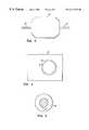
- FIG. 1 of whichis a schematic cross section of a flat sheet membrane permeator
- FIG. 2is the top view of its product hydrogen plenum
- FIG. 3is the top view of its turbulence promoters-containing plenum
- FIG. 4is the top view of a plenum-holding plate, of which there are two;
- FIG. 5is the top view of its porous membrane support at the center fitted into a non-porous rim
- FIG. 6is a cross section of the flat membrane pack
- FIG. 7is a schematic drawing of the two step process of reforming and hydrogen permeation
- FIG. 8is a schematic drawing or simultaneous reforming and hydrogen permeation
- FIG. 9is a schematic drawing of a tubular membrane assembly.
- a hydrogen collection plenum 1is shown formed of a preferably stainless steel open-bottom chamber (for example, 1 ⁇ 2 inch thick, 1 ⁇ 2 inch deep with a 1 ⁇ 8 inch wall thickness), bearing a stainless steel ⁇ fraction (1/4) ⁇ inch tubing 1′.
- the plenum 2which contains a non-catalytic and/or catalytic turbulence promoter 6, is a stainless steel open-top chamber, having the following dimensions for the experiment here described: 3.5 inches long, 2.5 inches wide and 1 ⁇ 8 inch thick, and bearing 1 ⁇ 8 inch stainless steel inlet and outlet cross-flow tubes 2 ′. Chambers 1 and 2 are welded to stainless steel face plates 3 and 3 ′, respectively, each plate being 4 inches long, 3 inches wide and 1 ⁇ 8 inch thick, and with knife edges 4 .
- FIG. 2also shows the plenum 1 , having welded thereto, two tubes 1 ′ (outlet and purge) arranged, for convenience, without need for cross-flow.
- the plenum 2is provided with cross-flow inlet and outlet tubes 2 ′ welded thereto.
- the plenum-holding plates 2 or 2 ′have chambers with circular openings 5 , 1.5 inches in diameter, and again are provided with the knife edges 4 .
- FIG. 5illustrates the membrane support which is shown as a porous stainless steel disc 11 ′, for example, one inch in diameter and 1 ⁇ 8 inch thick, press-fitted into a stainless steel retainer ring 11 , one inch i.d, two inches o.d. and 1 ⁇ 8 inch thick.
- the active area of the membraneis thus equal to the area of the porous disc 11 ′, i.e. 0.785 square inches (ca. 5 cm 2 ).
- FIG. 6the cross section of the membrane pack 7 is shown, which is the center piece of the membrane permeator.
- the packconsists of copper gaskets 8 , standard “Conflat” (Trade Mark), 1 ⁇ fraction (7/16) ⁇ inches i.d.
- Teflon gasketing ribbons 9sold under the Trade Name GORETEX by W. L. Gore & Associates, Inc. of Elkton, Md.
- the membrane packis made leak-proof by compressing it between two steel plates held in place by appropriate bolts (not shown in the figures).
- a reforming processis illustrated wherein a liquid methanol/water feed 12 , in the ratio of one mole of methanol and 2 mole of water, is fed by pump 13 , at the rate of 0.7 cc/min, to a heat-insulated (insulation not shown) pressurized vaporizer 14 at 30-40 psi, measured by gauge 15 .
- the vaporized mixturepasses into an insulated reactor (insulation again not shown) containing a catalyst bed 17 , which consists of 25 grams of a commercial methanol reforming catalyst, identified by United Catalysts Inc. of Louisville, Ky., comprising copper oxide as the active element mixed with other inorganic oxides.
- the catalyst bed temperatureis kept at 240° C.
- the effluent from the catalyst bedi.e. the reformate
- the assemblycomprises the membrane pack 7 which contains in its plenum 2 , as an example of a non-catalytic turbulence promoter, about 25 grams of broken glass frits 20 , about 10 ⁇ 10 ⁇ 3 mm.
- the reformate streamflows in a tortuous path 21 through the turbulence-promoting glass frits longitudinally across the membrane 10 .
- the membrane temperatureis maintained at 320° C., measured by thermocouple 19 ′ and held constant by controller 18 ′ (heating elements not shown).
- the membraneis a 1 mil thick palladium/23% silver alloy foil separating the hydrogen product 22 from the hydrogen-depleted reformate 24 , which still contains about 58% residual hydrogen, 19% CO 2 , 2% CO and 21% H 2 O and is vented through valve 23 .
- the pure hydrogen product 22was maintained at atmospheric pressure and was generated at a flux of 8.2 cc/cm 2 -min. under a differential hydrogen pressure of 16 psi. Its purity has been ascertained by gas chromatographic analysis showing no detectable carbon oxides.
- Table 4shows the results of these experiments in which the ratios Q/Q° are recorded versus the upstream composition.
- Qi.e. the pure hydrogen flux from the impure reformate or synthetic mixture
- Q°(10.6 cc/cm 2 -min.), i.e. the flux from pure hydrogen upstream
- the hydrogen swelling of the palladium/copper alloy membraneis minimal, allowing the use of flat membrane foils sealed under compression, as illustrated in the above figures.
- the palladium copper alloyis activated by hydrogen without exposure to oxygen, again in contrast to the other alloys.
- the glass frits in the membrane assembly 7 above describedare replaced by 12 grams of the reforming catalyst 17 in particulate cylindrical form (1 ⁇ 4′′ diameter ⁇ 1 ⁇ 8′′ height) and the membrane 10 therein is now a one mil thick palladium/40% (by weight) copper alloy foil.
- Controller 18holds the membrane reactor at 290° C., measured by thermocouple 19 .
- the reactants 12composed of 1.1 mol water and 1 mol methanol, are fed at a liquid flow rate of 0.12 ml/min. by pump 13 to the pressurized vaporizer 14 and thence to the membrane pack 7 in the assembly 20 , flowing again longitudinally across the membrane in a turbulent tortuous path 21 across the granular catalyst bed.
- the reformate pressuremeasured at gauge 15 , is varied between 60 and 200 psig.
- the membrane assembly reactoragain heat insulated by fiber glass 25 , is maintained at 290° C., measured by thermocouple 19 , by controller 18 .
- the pure hydrogen 22is produced and maintained at atmospheric pressure.
- the feed pressurewas varied between 60 and 200 psig.
- the spent permeatewas vented through pressure control valve 23 .
- the pure hydrogen productis collected at atmospheric pressure from plenum 1 .
- the CO concentration in the spent permeatewas found to be 2.5%, at the total pressure of 120 psig, that is one half the 5% CO, based on equilibrium calculations, that is expected, when the permeation is performed without the presence of the catalyst adjacent to the membrane.
- the in-situ catalyst systemis thus seen to perform, in addition to steam reforming, three simultaneous functions: 1) promoting turbulence, 2) enhancing methanol conversion, and 3) substantially reducing the CO concentration, the latter, presumably, by shifting the equilibrium of the catalytic water-gas reaction ⁇ equation (2) discussed above ⁇ in the vicinity of the membrane.
- the important third functionenables the safe use of a nearly stoichiometric amount of steam, e.g. only one-tenth of a mole excess steam per mole of methanol shown in this Example, without membrane poisoning.
- tubular (palladium-bearing) membranesinstead of planar ones, is well known in the prior art, as shown, for instance, in the above-referred-to publication by R. Goto, includes the cell depicted in FIG. 13 (page 49) and the description of its assembly.
- Goto's cell assemblyis converted to a membrane reactor of the type involved in the present invention as follows.
- Tubular membranes 10e.g. the silver/palladium alloy tubes described by Goto or a palladium-coated transition base metal described in U.S. Pat. No. 5,498,278 (col. 3, line 22-24)
- Tubular membranes 10e.g. the silver/palladium alloy tubes described by Goto or a palladium-coated transition base metal described in U.S. Pat. No. 5,498,278 (col. 3, line 22-24)
- reforming catalyst 17crushed and sieved to particle sizes between 10 and 20 mesh.
- the packed catalyst bedis held in place by uniformly porous means 26 and 26 ′, here two 40 mesh stainless-steel screens.
- One, 26,is located above the bottom inlet plenum 2 ′ of the reactants; it is not only the catalyst support, but also a flow distributor which is spaced above the inlet to plenum 2 ′ to insure substantially equalized flow of the reactants through the catalyst bed.
- the other, 26 ′located at the top of the catalyst bed, prevents entrainment of catalyst particles by the gas flow.
- the membrane tubes 10are mounted, as by brazing or welding, on a gas-impervious, e.g. stainless steel top plate 27 , spaced above screen 26 ′ at the top, which separates the outlet plenum 2 ′′ of the spent reformate from the pure hydrogen product plenum 1 .
- the open and closed ends of the tubesare located, respectively, in plenum 1 and within the catalyst bed, preferably, spaced above the catalyst support 26 , as shown in FIG. 9 .
- This latter spacingis provided in the in-situ membrane reactor to initiate the reforming reaction before the reactants contact the membranes.
- Methanol conversionis preferably carried out to substantial completion, but a controlled amount of residual hydrogen, between about 5 and 20% of the total generated, is maintained in the spent reformate at a partial pressure therein exceeding the pure hydrogen pressure down-stream.
- the unit with palladium/silver alloy tubesis operated with external heating, the temperature is set at 320° C. and the total pressure is maintained at 150 psig (controls not shown in FIG. 9, except for pressure gauge 15 ).
- the reactants 12consisting of 1.1 mol H 2 O to 1 mol CH 3 OH, are fed by pump 13 to the pressurized vaporizer 14 at a liquid flow rate of 0.02 ml/min.- cm 2 of membrane area exposed to the reactants, the methanol conversion, with 5-15% pre-reforming, is substantially complete and 75-80% of the hydrogen generated in the reactor is permeated as the pure hydrogen product 22 , at a controlled pressure of 25 psi, exiting from plenum 1 through valve 27 .
- the spent reformateis vented from plenum 2 ′′ through control valve 23 .
- the pressurized vaporizeris, by way of illustration, provided with a jacket 28 , which is filled with, for example, a granular platinum-bearing oxidation catalyst 29 , such as any one described, by way of one example of many of the prior art, in U.S. Pat. No. 4,082,699 to Petrow et al., incorporated herein by reference.
- the hot pressurized spent reformate 24entrains the appropriate amount of air or oxygen 30 through Venturi valve 31 and the resulting mixture is catalytically oxidized in jacket 28 and exhausted at 29 free of carbon monoxide and of hydrogen.
- the amount of residual hydrogen in the spent reformateis conveniently controlled to generate sufficient heat, together with the carbon monoxide oxidation, for vaporizing and superheating the reactants to supply substantially all the energy needs. Note that the hydrogen will light off spontaneously upon contacting the oxidation catalyst and cause light off of the carbon monoxide.
- the so superheated reactantsexit the pressurized vaporizer 14 and are fed to plenum 2 ′, and thence through reactor/permeator as in Example 3.
- the space velocity of the incoming reactantsi.e. their volume per hour per unit volume of reforming catalyst, is controlled, at the operating temperature of 290° C., to cause (1) substantially complete methanol conversion, (2) 10-15% pre-reforming and (3) permeation of 75-80% of the total hydrogen generated.
- the exit pressure of the spent reformateis maintained at 200 psi and the pure hydrogen is produced 30 psi.
Landscapes
- Chemical & Material Sciences (AREA)
- Organic Chemistry (AREA)
- Chemical Kinetics & Catalysis (AREA)
- Engineering & Computer Science (AREA)
- Combustion & Propulsion (AREA)
- General Chemical & Material Sciences (AREA)
- Inorganic Chemistry (AREA)
- Sustainable Development (AREA)
- Life Sciences & Earth Sciences (AREA)
- Sustainable Energy (AREA)
- Electrochemistry (AREA)
- Manufacturing & Machinery (AREA)
- Physics & Mathematics (AREA)
- Fluid Mechanics (AREA)
- Health & Medical Sciences (AREA)
- General Health & Medical Sciences (AREA)
- Analytical Chemistry (AREA)
- Oil, Petroleum & Natural Gas (AREA)
- Hydrogen, Water And Hydrids (AREA)
Abstract
Description
| TABLE 1 |
| Poisoning of a Pd/25% Ag membrane by a mixture of 98.4% |
| hydrogen and 1.6% CO after 100 hours of operation vs. temperature. |
| Temperature (° C.) | Q/Q° | ||
| 330 | 0.98 | ||
| 300 | 0.85 | ||
| 275 | 0.65 | ||
| 250 | 0.17 | ||
| 200 | 0.03 | ||
| 150 | zero | ||
| TABLE 2 |
| Poisoning (same membrane) by 1%, 1.6%, and 2% CO in hydrogen |
| after one and one-half hour operation at 150° C. |
| CO concentration | Q/Q° | ||
| 1.0% | 0.32 | ||
| 1.6% | 0.18 | ||
| 2.0% | 0.02 | ||
| TABLE 3 |
| Aggravation of CO-poisoning by carbon dioxide and steam, after |
| two and one half-hours of operation at 200° C. |
| gas composition (ex H2) | Q/Q° | ||
| 2% CO | 0.4 | ||
| 1.6% CO + 12% H2O | 0.01 | ||
| 1.6% CO + 6% CO2 | 0.27 | ||
| 1.6% CO + 22% CO2 | 0.07 | ||
| TABLE 4 |
| Turbulence effect: steady state operation at 320° C. (same membrane), |
| without and with glass frits promoters. |
| Q/Q° | Q/Q° | |||
| Gas composition | no turbulence | turbulence | ||
| 67-68% H2+ 33-32% CO2 | 0.71 | 0.92 | ||
| Reformate | 0.32 | 0.77 | ||
| TABLE 5 | |||
| Total | CH3OH | H2Permeation | Flux |
| Pressure (psig) | Conversion (%) | (%) | (cc/cm2-min) |
| 97 | 99 | 41 | 12 |
| 108 | 99 | 47 | 14 |
| 147 | 98 | 50 | 15 |
| 180 | 93 | 57 | 16 |
Claims (13)
Priority Applications (1)
| Application Number | Priority Date | Filing Date | Title |
|---|---|---|---|
| US08/719,385US6171574B1 (en) | 1996-09-24 | 1996-09-24 | Method of linking membrane purification of hydrogen to its generation by steam reforming of a methanol-like fuel |
Applications Claiming Priority (1)
| Application Number | Priority Date | Filing Date | Title |
|---|---|---|---|
| US08/719,385US6171574B1 (en) | 1996-09-24 | 1996-09-24 | Method of linking membrane purification of hydrogen to its generation by steam reforming of a methanol-like fuel |
Publications (1)
| Publication Number | Publication Date |
|---|---|
| US6171574B1true US6171574B1 (en) | 2001-01-09 |
Family
ID=24889870
Family Applications (1)
| Application Number | Title | Priority Date | Filing Date |
|---|---|---|---|
| US08/719,385Expired - Fee RelatedUS6171574B1 (en) | 1996-09-24 | 1996-09-24 | Method of linking membrane purification of hydrogen to its generation by steam reforming of a methanol-like fuel |
Country Status (1)
| Country | Link |
|---|---|
| US (1) | US6171574B1 (en) |
Cited By (74)
| Publication number | Priority date | Publication date | Assignee | Title |
|---|---|---|---|---|
| US6274096B1 (en) | 1999-11-01 | 2001-08-14 | Acetex (Cyprus) Limited | Methanol plant retrofit |
| US6319306B1 (en) | 2000-03-23 | 2001-11-20 | Idatech, Llc | Hydrogen-selective metal membrane modules and method of forming the same |
| US6376113B1 (en) | 1998-11-12 | 2002-04-23 | Idatech, Llc | Integrated fuel cell system |
| US6383670B1 (en) | 1999-10-06 | 2002-05-07 | Idatech, Llc | System and method for controlling the operation of a fuel processing system |
| US6419726B1 (en) | 1999-10-21 | 2002-07-16 | Ati Properties, Inc. | Fluid separation assembly and fluid separation module |
| US6419728B1 (en) | 1999-03-22 | 2002-07-16 | Idatech, Llc | Hydrogen-permeable metal membrane and method for producing the same |
| FR2820416A1 (en)* | 2001-02-07 | 2002-08-09 | Cie D Etudes Des Technologies | METHOD AND DEVICE FOR THE PRODUCTION OF HYDROGEN BY PARTIAL OXIDATION OF HYDROCARBON FUELS |
| US20020141920A1 (en)* | 2001-03-30 | 2002-10-03 | Alvin Mary Anne | Metal gas separation membrane module design |
| US6465118B1 (en) | 2000-01-03 | 2002-10-15 | Idatech, Llc | System and method for recovering thermal energy from a fuel processing system |
| US20030008186A1 (en)* | 2001-06-26 | 2003-01-09 | Dickman Anthony J. | Fuel processor feedstock delivery system |
| US6531630B2 (en) | 2000-12-29 | 2003-03-11 | Kenneth Ebenes Vidalin | Bimodal acetic acid manufacture |
| US6537352B2 (en) | 1996-10-30 | 2003-03-25 | Idatech, Llc | Hydrogen purification membranes, components and fuel processing systems containing the same |
| US6537691B1 (en)* | 1998-10-17 | 2003-03-25 | Ballard Power Systems Ag | Container for receiving an operating means for the operation of fuel cells |
| US6562111B2 (en) | 2001-09-27 | 2003-05-13 | Idatech, Llc | Hydrogen purification devices, components and fuel processing systems containing the same |
| US6569227B2 (en) | 2001-09-27 | 2003-05-27 | Idatech, Llc | Hydrogen purification devices, components and fuel processing systems containing the same |
| US6582499B2 (en)* | 1998-11-10 | 2003-06-24 | Ati Properties, Inc. | Fluid separation assembly |
| US6596057B2 (en) | 1999-03-22 | 2003-07-22 | Idatech, Llc | Hydrogen-selective metal membranes, membrane modules, purification assemblies and methods of forming the same |
| US6599491B2 (en) | 2001-01-22 | 2003-07-29 | Kenneth Ebenes Vidalin | Bimodal hydrogen manufacture |
| US6602325B1 (en) | 1999-10-21 | 2003-08-05 | Ati Properties, Inc. | Fluid separation assembly |
| US20030159354A1 (en)* | 1996-10-30 | 2003-08-28 | Edlund David J. | Fuel processing system |
| US20030167690A1 (en)* | 2002-03-05 | 2003-09-11 | Edlund David J. | Feedstock delivery system and fuel processing systems containing the same |
| US20030172589A1 (en)* | 2002-03-12 | 2003-09-18 | Krueger Charles W. | Steam-reforming catalytic structure and pure hydrogen generator comprising the same and method of operation of same |
| US20030219637A1 (en)* | 2002-05-22 | 2003-11-27 | Coors W. Grover | Direct hydrocarbon reforming in protonic ceramic fuel cells by electrolyte steam permeation |
| US6660069B2 (en)* | 2001-07-23 | 2003-12-09 | Toyota Jidosha Kabushiki Kaisha | Hydrogen extraction unit |
| US20040060437A1 (en)* | 1998-11-10 | 2004-04-01 | Frost Chester B | Fluid separation assembly and fluid separation module |
| US6756020B1 (en)* | 1999-08-06 | 2004-06-29 | Ballard Power Systems Ag | Combined component for afterburning anode exhaust gases from a fuel cell system and for vaporizing educts delivered by the fuel cell system |
| US20040134348A1 (en)* | 2003-01-13 | 2004-07-15 | Ati Properties, Inc. (A Delaware Corporation) | Hydrogen reclamation apparatus and method |
| US6767389B2 (en) | 1999-03-22 | 2004-07-27 | Idatech, Llc | Hydrogen-selective metal membranes, membrane modules, purification assemblies and methods of forming the same |
| US20040154223A1 (en)* | 2001-03-02 | 2004-08-12 | Powell Michael Roy | Ammonia-based hydrogen generation apparatus and method for using same |
| US6781014B1 (en) | 1999-11-01 | 2004-08-24 | Acetex (Cyprus) Limited | Methanol plant retrofit for manufacture of acetic acid |
| US20050061145A1 (en)* | 2003-09-24 | 2005-03-24 | Siemens Westinghouse Power Corporation | Metal gas separation membrane |
| US6967063B2 (en) | 2001-05-18 | 2005-11-22 | The University Of Chicago | Autothermal hydrodesulfurizing reforming method and catalyst |
| US20050266284A1 (en)* | 2004-05-28 | 2005-12-01 | Mesa Scharf | Consumption-based fuel cell monitoring and control |
| WO2006005269A2 (en) | 2004-07-09 | 2006-01-19 | Acetex (Cyprus) Limited | Preparati0n of syngas for acetic acid synthesis by partial oxidation of methanol feedstock |
| US20060024540A1 (en)* | 2004-07-29 | 2006-02-02 | Laven Arne | Shared variable-based fuel cell system control |
| US20060037476A1 (en)* | 2001-03-08 | 2006-02-23 | Edlund David J | Hydrogen purification devices, components and fuel processing systems containing the same |
| US20060054512A1 (en)* | 2004-09-14 | 2006-03-16 | Ballantine Arne W | Methods, devices, and infrastructure systems for separating, removing, compressing, and generating hydrogen |
| US20060057440A1 (en)* | 2004-09-14 | 2006-03-16 | Ballantine Arne W | Fuel cells and methods for generating electricity |
| US20060060084A1 (en)* | 2004-09-20 | 2006-03-23 | Edlund David J | Hydrogen purification devices, components, and fuel processing systems containing the same |
| US20060090397A1 (en)* | 2004-10-31 | 2006-05-04 | Edlund David J | Hydrogen generation and energy production assemblies |
| US20060090396A1 (en)* | 2004-10-29 | 2006-05-04 | Edlund David J | Feedstock delivery systems, fuel processing systems, and hydrogen generation assemblies including the same |
| US20060112636A1 (en)* | 2001-03-02 | 2006-06-01 | Anand Chellappa | Ammonia-based hydrogen generation apparatus and method for using same |
| US20060137245A1 (en)* | 2004-12-17 | 2006-06-29 | Texaco Inc. | Apparatus and method for producing hydrogen |
| US20060188737A1 (en)* | 2002-04-03 | 2006-08-24 | Colorado School Of Mines | Process for Preparing Palladium Alloy Composite Membranes for Use in Hydrogen Separation, Palladium Alloy Composite Membranes and Products Incorporating or Made from the Membranes |
| US20060213369A1 (en)* | 1996-10-30 | 2006-09-28 | Edlund David J | Hydrogen purification membranes, components and fuel processing systems containing the same |
| US20060233700A1 (en)* | 2005-04-18 | 2006-10-19 | Anand Chellappa | Compact devices for generating pure hydrogen |
| US7255949B2 (en) | 2004-05-25 | 2007-08-14 | Protonetics International, Inc. | Systems and methods to generate hydrogen and electrical power in a reversible compound fuel cell |
| US20070264546A1 (en)* | 2006-05-15 | 2007-11-15 | Laven Arne | Hydrogen-producing fuel cell systems with load-responsive feedstock delivery systems |
| US20070266631A1 (en)* | 2006-05-22 | 2007-11-22 | Pledger William A | Hydrogen-processing assemblies and hydrogen-producing systems and fuel cell systems including the same |
| US20070274904A1 (en)* | 2006-05-23 | 2007-11-29 | Vernon Wade Popham | Hydrogen-producing fuel processing assemblies, heating assemblies, and methods of operating the same |
| US20080038567A1 (en)* | 2002-04-03 | 2008-02-14 | Way J D | Sulfur-Resistant composite Metal Membranes |
| US20080107593A1 (en)* | 2006-03-23 | 2008-05-08 | Ngk Insulators, Ltd. | Process for producing hydrogen with permselective membrane reactor and permselective membrane reactor |
| US20080187794A1 (en)* | 2007-02-07 | 2008-08-07 | Bloom Energy Corporation | Venturi catalytic reactor inlet fuel mixer |
| US20080210088A1 (en)* | 2006-10-23 | 2008-09-04 | Idatech, Llc | Hydrogen purification membranes, components and fuel processing systems containing the same |
| US20080222954A1 (en)* | 2005-09-16 | 2008-09-18 | Idatech, Llc | Self-Regulating Feedstock Delivery Systems and Hydrogen-Generating Fuel Processing Assemblies and Fuel Cell Systems Incorporating the Same |
| CN100469417C (en)* | 2005-03-15 | 2009-03-18 | 大连欧科膜技术工程有限公司 | A system for recovering hydrogen in the air during methanol synthesis by membrane method |
| US20090155642A1 (en)* | 2007-12-17 | 2009-06-18 | Idatech, Llc | Systems and methods for reliable feedstock delivery at variable delivery rates |
| US20090176012A1 (en)* | 2007-08-22 | 2009-07-09 | Way J Douglas | Unsupported Palladium Alloy Membranes and Methods of Making Same |
| US7601302B2 (en) | 2005-09-16 | 2009-10-13 | Idatech, Llc | Self-regulating feedstock delivery systems and hydrogen-generating fuel processing assemblies and fuel cell systems incorporating the same |
| US20100068132A1 (en)* | 2002-04-23 | 2010-03-18 | Vencill Thomas R | Array of planar membrane modules for producing hydrogen |
| US7922781B2 (en) | 2001-03-02 | 2011-04-12 | Chellappa Anand S | Hydrogen generation apparatus and method for using same |
| US8778058B2 (en) | 2010-07-16 | 2014-07-15 | Colorado School Of Mines | Multilayer sulfur-resistant composite metal membranes and methods of making and repairing the same |
| EP2708494A4 (en)* | 2011-05-09 | 2014-12-24 | Korea Energy Research Inst | APPARATUS FOR REFORMING A HYDROCARBON USING A MICRO-CHANNEL HEATING DEVICE |
| US8961627B2 (en) | 2011-07-07 | 2015-02-24 | David J Edlund | Hydrogen generation assemblies and hydrogen purification devices |
| US20150202564A1 (en)* | 2013-01-22 | 2015-07-23 | Robert E. Kirby | Method For Permeation Extraction of Hydrogen From an Enclosed Volume |
| US9187324B2 (en) | 2012-08-30 | 2015-11-17 | Element 1 Corp. | Hydrogen generation assemblies and hydrogen purification devices |
| US9914641B2 (en) | 2012-08-30 | 2018-03-13 | Element 1 Corp. | Hydrogen generation assemblies |
| US20190209997A1 (en)* | 2018-01-09 | 2019-07-11 | Innoveering, LLC | Fuel reformation for use in high speed propulsion systems |
| US10476093B2 (en) | 2016-04-15 | 2019-11-12 | Chung-Hsin Electric & Machinery Mfg. Corp. | Membrane modules for hydrogen separation and fuel processors and fuel cell systems including the same |
| US10717040B2 (en) | 2012-08-30 | 2020-07-21 | Element 1 Corp. | Hydrogen purification devices |
| CN114922729A (en)* | 2022-05-18 | 2022-08-19 | 福建中源新能源股份有限公司 | Vehicle-mounted methanol hydrogen production system |
| CN116143076A (en)* | 2023-02-23 | 2023-05-23 | 浙江大学 | Laminated hydrogen purification membrane reactor |
| US11712655B2 (en) | 2020-11-30 | 2023-08-01 | H2 Powertech, Llc | Membrane-based hydrogen purifiers |
| US11738305B2 (en) | 2012-08-30 | 2023-08-29 | Element 1 Corp | Hydrogen purification devices |
Citations (5)
| Publication number | Priority date | Publication date | Assignee | Title |
|---|---|---|---|---|
| US4810485A (en)* | 1986-08-25 | 1989-03-07 | Institute Of Gas Technology | Hydrogen forming reaction process |
| US4981676A (en)* | 1989-11-13 | 1991-01-01 | Minet Ronald G | Catalytic ceramic membrane steam/hydrocarbon reformer |
| US5215729A (en)* | 1990-06-22 | 1993-06-01 | Buxbaum Robert E | Composite metal membrane for hydrogen extraction |
| US5229102A (en)* | 1989-11-13 | 1993-07-20 | Medalert, Inc. | Catalytic ceramic membrane steam-hydrocarbon reformer |
| US5741474A (en)* | 1994-05-23 | 1998-04-21 | Ngk Insulators, Ltd. | Process for production of high-purity hydrogen |
- 1996
- 1996-09-24USUS08/719,385patent/US6171574B1/ennot_activeExpired - Fee Related
Patent Citations (5)
| Publication number | Priority date | Publication date | Assignee | Title |
|---|---|---|---|---|
| US4810485A (en)* | 1986-08-25 | 1989-03-07 | Institute Of Gas Technology | Hydrogen forming reaction process |
| US4981676A (en)* | 1989-11-13 | 1991-01-01 | Minet Ronald G | Catalytic ceramic membrane steam/hydrocarbon reformer |
| US5229102A (en)* | 1989-11-13 | 1993-07-20 | Medalert, Inc. | Catalytic ceramic membrane steam-hydrocarbon reformer |
| US5215729A (en)* | 1990-06-22 | 1993-06-01 | Buxbaum Robert E | Composite metal membrane for hydrogen extraction |
| US5741474A (en)* | 1994-05-23 | 1998-04-21 | Ngk Insulators, Ltd. | Process for production of high-purity hydrogen |
Cited By (175)
| Publication number | Priority date | Publication date | Assignee | Title |
|---|---|---|---|---|
| US6824593B2 (en) | 1996-10-30 | 2004-11-30 | Idatech, Llc | Hydrogen purification membranes, components and fuel processing systems containing the same |
| US8057575B2 (en) | 1996-10-30 | 2011-11-15 | Idatech, Llc | Hydrogen purification membranes, components and fuel processing systems containing the same |
| US7052530B2 (en) | 1996-10-30 | 2006-05-30 | Idatech, Llc | Hydrogen purification membranes, components and fuel processing systems containing the same |
| US20060213369A1 (en)* | 1996-10-30 | 2006-09-28 | Edlund David J | Hydrogen purification membranes, components and fuel processing systems containing the same |
| US20050188843A1 (en)* | 1996-10-30 | 2005-09-01 | Edlund David J. | Hydrogen purification membranes, components and fuel processing systems containing the same |
| US20030159354A1 (en)* | 1996-10-30 | 2003-08-28 | Edlund David J. | Fuel processing system |
| US20070251387A1 (en)* | 1996-10-30 | 2007-11-01 | Edlund David J | Hydrogen purification membranes, components and fuel processing systems containing the same |
| US7819955B2 (en) | 1996-10-30 | 2010-10-26 | Idatech, Llc | Hydrogen purification membranes, components and fuel processing systems containing the same |
| US7789941B2 (en) | 1996-10-30 | 2010-09-07 | Idatech, Llc | Hydrogen purification membranes, components and fuel processing systems containing the same |
| US7410531B2 (en) | 1996-10-30 | 2008-08-12 | Idatech, Llc | Hydrogen purification membranes, components and fuel processing systems containing the same |
| US6783741B2 (en)* | 1996-10-30 | 2004-08-31 | Idatech, Llc | Fuel processing system |
| US8636828B2 (en) | 1996-10-30 | 2014-01-28 | Dcns Sa | Hydrogen purification membranes, components and fuel processing systems containing the same |
| US20090202873A1 (en)* | 1996-10-30 | 2009-08-13 | Idatech, Llc | Hydrogen purification membranes, components and fuel processing systems containing the same |
| US6723156B2 (en) | 1996-10-30 | 2004-04-20 | Idatech, Llc | Hydrogen purification membranes, components and fuel processing systems containing the same |
| US8257466B2 (en) | 1996-10-30 | 2012-09-04 | Idatech, Llc | Hydrogen purification membranes, components and fuel processing systems containing the same |
| US20090202874A1 (en)* | 1996-10-30 | 2009-08-13 | Idatech, Llc | Hydrogen purification membranes, components and fuel processing systems containing the same |
| US6719831B2 (en) | 1996-10-30 | 2004-04-13 | Idatech, Llc | Hydrogen purification membranes, components and fuel processing systems containing the same |
| US6537352B2 (en) | 1996-10-30 | 2003-03-25 | Idatech, Llc | Hydrogen purification membranes, components and fuel processing systems containing the same |
| US20040083890A1 (en)* | 1996-10-30 | 2004-05-06 | Edlund David J. | Hydrogen purification membranes, components and fuel processing systems containing the same |
| US6632270B2 (en) | 1996-10-30 | 2003-10-14 | Idatech, Llc | Hydrogen purification membranes, components and fuel processing systems containing the same |
| US20110116985A1 (en)* | 1996-10-30 | 2011-05-19 | Idatech, Llc | Hydrogen purification membranes, components and fuel processing systems containing the same |
| US7195663B2 (en) | 1996-10-30 | 2007-03-27 | Idatech, Llc | Hydrogen purification membranes, components and fuel processing systems containing the same |
| US6537691B1 (en)* | 1998-10-17 | 2003-03-25 | Ballard Power Systems Ag | Container for receiving an operating means for the operation of fuel cells |
| US6582499B2 (en)* | 1998-11-10 | 2003-06-24 | Ati Properties, Inc. | Fluid separation assembly |
| US6835232B2 (en) | 1998-11-10 | 2004-12-28 | Frost Chester B | Fluid separation assembly and fluid separation module |
| US20040060437A1 (en)* | 1998-11-10 | 2004-04-01 | Frost Chester B | Fluid separation assembly and fluid separation module |
| US6994927B2 (en) | 1998-11-12 | 2006-02-07 | Idatech, Llc | Integrated fuel cell system |
| US20060216562A1 (en)* | 1998-11-12 | 2006-09-28 | Edlund David J | Integrated fuel cell system |
| US6376113B1 (en) | 1998-11-12 | 2002-04-23 | Idatech, Llc | Integrated fuel cell system |
| US20050181248A1 (en)* | 1998-11-12 | 2005-08-18 | Edlund David J. | Integrated fuel cell system |
| US6869707B2 (en) | 1998-11-12 | 2005-03-22 | Idatech, Llc | Integrated fuel cell system |
| US20020119353A1 (en)* | 1998-11-12 | 2002-08-29 | Edlund David J. | Integrated fuel cell system |
| US6767389B2 (en) | 1999-03-22 | 2004-07-27 | Idatech, Llc | Hydrogen-selective metal membranes, membrane modules, purification assemblies and methods of forming the same |
| US7101421B2 (en) | 1999-03-22 | 2006-09-05 | Idatech, Llc | Hydrogen-selective metal membranes, membrane modules, purification assemblies and methods of forming the same |
| US6596057B2 (en) | 1999-03-22 | 2003-07-22 | Idatech, Llc | Hydrogen-selective metal membranes, membrane modules, purification assemblies and methods of forming the same |
| US6419728B1 (en) | 1999-03-22 | 2002-07-16 | Idatech, Llc | Hydrogen-permeable metal membrane and method for producing the same |
| US20040244591A1 (en)* | 1999-03-22 | 2004-12-09 | Edlund David J. | Hydrogen-selective metal membranes, membrane modules, purification assemblies and methods of forming the same |
| US6756020B1 (en)* | 1999-08-06 | 2004-06-29 | Ballard Power Systems Ag | Combined component for afterburning anode exhaust gases from a fuel cell system and for vaporizing educts delivered by the fuel cell system |
| US6811908B2 (en) | 1999-10-06 | 2004-11-02 | Idatech, Llc | System and method for controlling the operation of a fuel processing system |
| US20080176118A1 (en)* | 1999-10-06 | 2008-07-24 | Edlund David J | System and method for controlling the operation of a fuel processsing system |
| US7939211B2 (en) | 1999-10-06 | 2011-05-10 | Idatech, Llc | System and method for controlling the operation of a fuel processing system |
| US6383670B1 (en) | 1999-10-06 | 2002-05-07 | Idatech, Llc | System and method for controlling the operation of a fuel processing system |
| US20050106431A1 (en)* | 1999-10-06 | 2005-05-19 | Edlund David J. | System and method for controlling the operation of a fuel processing system |
| US7208241B2 (en) | 1999-10-06 | 2007-04-24 | Idatech, Llc | System and method for controlling the operation of a fuel processing system |
| US20020127447A1 (en)* | 1999-10-06 | 2002-09-12 | Edlund David J. | System and method for controlling the operation of a fuel processing system |
| US7771882B2 (en) | 1999-10-06 | 2010-08-10 | Idatech, Llc | System and method for controlling the operation of a fuel processing system |
| US6602325B1 (en) | 1999-10-21 | 2003-08-05 | Ati Properties, Inc. | Fluid separation assembly |
| US6419726B1 (en) | 1999-10-21 | 2002-07-16 | Ati Properties, Inc. | Fluid separation assembly and fluid separation module |
| US6274096B1 (en) | 1999-11-01 | 2001-08-14 | Acetex (Cyprus) Limited | Methanol plant retrofit |
| US6353133B1 (en) | 1999-11-01 | 2002-03-05 | Acetex (Cyprus) Limited | Methanol plant retrofit |
| US6781014B1 (en) | 1999-11-01 | 2004-08-24 | Acetex (Cyprus) Limited | Methanol plant retrofit for manufacture of acetic acid |
| US6878474B2 (en) | 2000-01-03 | 2005-04-12 | Idatech, Llc | System and method for recovering thermal energy from a fuel processing system |
| US20030049502A1 (en)* | 2000-01-03 | 2003-03-13 | Dickman Anthony J. | System and method for recovering thermal energy from a fuel processing system |
| US20050164052A1 (en)* | 2000-01-03 | 2005-07-28 | Dickman Anthony J. | System and method for recovering thermal energy from a fuel processing system |
| US6465118B1 (en) | 2000-01-03 | 2002-10-15 | Idatech, Llc | System and method for recovering thermal energy from a fuel processing system |
| US7485381B2 (en) | 2000-01-03 | 2009-02-03 | Idatech, Llc | System and method for recovering thermal energy from a fuel processing system |
| US6458189B1 (en) | 2000-03-23 | 2002-10-01 | Idatech, Llc | Hydrogen-selective metal membrane modules and method of forming the same |
| US6319306B1 (en) | 2000-03-23 | 2001-11-20 | Idatech, Llc | Hydrogen-selective metal membrane modules and method of forming the same |
| US6531630B2 (en) | 2000-12-29 | 2003-03-11 | Kenneth Ebenes Vidalin | Bimodal acetic acid manufacture |
| US6599491B2 (en) | 2001-01-22 | 2003-07-29 | Kenneth Ebenes Vidalin | Bimodal hydrogen manufacture |
| WO2002062700A3 (en)* | 2001-02-07 | 2002-11-28 | Cie D Etudes Des Technologies | Method and device for producing hydrogen by partial oxidation of hydrocarbon fuels |
| FR2820416A1 (en)* | 2001-02-07 | 2002-08-09 | Cie D Etudes Des Technologies | METHOD AND DEVICE FOR THE PRODUCTION OF HYDROGEN BY PARTIAL OXIDATION OF HYDROCARBON FUELS |
| US7922781B2 (en) | 2001-03-02 | 2011-04-12 | Chellappa Anand S | Hydrogen generation apparatus and method for using same |
| US20060112636A1 (en)* | 2001-03-02 | 2006-06-01 | Anand Chellappa | Ammonia-based hydrogen generation apparatus and method for using same |
| US20040154223A1 (en)* | 2001-03-02 | 2004-08-12 | Powell Michael Roy | Ammonia-based hydrogen generation apparatus and method for using same |
| US7875089B2 (en) | 2001-03-02 | 2011-01-25 | Intelligent Energy, Inc. | Ammonia-based hydrogen generation apparatus and method for using same |
| US7867300B2 (en) | 2001-03-02 | 2011-01-11 | Intelligent Energy, Inc. | Ammonia-based hydrogen generation apparatus and method for using same |
| US20060037476A1 (en)* | 2001-03-08 | 2006-02-23 | Edlund David J | Hydrogen purification devices, components and fuel processing systems containing the same |
| US6913736B2 (en) | 2001-03-30 | 2005-07-05 | Siemens Westinghouse Power Corporation | Metal gas separation membrane module design |
| US20020141920A1 (en)* | 2001-03-30 | 2002-10-03 | Alvin Mary Anne | Metal gas separation membrane module design |
| US6967063B2 (en) | 2001-05-18 | 2005-11-22 | The University Of Chicago | Autothermal hydrodesulfurizing reforming method and catalyst |
| US7368194B2 (en) | 2001-06-26 | 2008-05-06 | Idatech, Llc | Fuel processor feedstock delivery system |
| US6890672B2 (en) | 2001-06-26 | 2005-05-10 | Idatech, Llc | Fuel processor feedstock delivery system |
| US7682718B2 (en) | 2001-06-26 | 2010-03-23 | Idatech, Llc | Fuel processor feedstock delivery system |
| US20080248347A1 (en)* | 2001-06-26 | 2008-10-09 | Idatech, Llc | Fuel processor feedstock delivery system |
| US20030008186A1 (en)* | 2001-06-26 | 2003-01-09 | Dickman Anthony J. | Fuel processor feedstock delivery system |
| US20050208351A1 (en)* | 2001-06-26 | 2005-09-22 | Dickman Anthony J | Fuel processor feedstock delivery system |
| US6660069B2 (en)* | 2001-07-23 | 2003-12-09 | Toyota Jidosha Kabushiki Kaisha | Hydrogen extraction unit |
| US6719832B2 (en) | 2001-09-27 | 2004-04-13 | Idatech, Llc | Hydrogen purification devices, components and fuel processing systems containing the same |
| US6953497B2 (en) | 2001-09-27 | 2005-10-11 | Idatech, Llc | Hydrogen purification devices, components and fuel processing systems containing the same |
| US20040231516A1 (en)* | 2001-09-27 | 2004-11-25 | Edlund David J. | Hydrogen purification devices, components and fuel processing systems containing the same |
| US6569227B2 (en) | 2001-09-27 | 2003-05-27 | Idatech, Llc | Hydrogen purification devices, components and fuel processing systems containing the same |
| US6562111B2 (en) | 2001-09-27 | 2003-05-13 | Idatech, Llc | Hydrogen purification devices, components and fuel processing systems containing the same |
| US20030167690A1 (en)* | 2002-03-05 | 2003-09-11 | Edlund David J. | Feedstock delivery system and fuel processing systems containing the same |
| US7182917B2 (en)* | 2002-03-12 | 2007-02-27 | Hy9 Corporation | Steam-reforming catalytic structure and pure hydrogen generator comprising the same and method of operation of same |
| US20030172589A1 (en)* | 2002-03-12 | 2003-09-18 | Krueger Charles W. | Steam-reforming catalytic structure and pure hydrogen generator comprising the same and method of operation of same |
| WO2003076062A3 (en)* | 2002-03-12 | 2003-11-27 | Hy9 Corp | Steam-reforming catalytic structures |
| US20060188737A1 (en)* | 2002-04-03 | 2006-08-24 | Colorado School Of Mines | Process for Preparing Palladium Alloy Composite Membranes for Use in Hydrogen Separation, Palladium Alloy Composite Membranes and Products Incorporating or Made from the Membranes |
| US20080038567A1 (en)* | 2002-04-03 | 2008-02-14 | Way J D | Sulfur-Resistant composite Metal Membranes |
| US8119205B2 (en) | 2002-04-03 | 2012-02-21 | Colorado School Of Mines | Process for preparing palladium alloy composite membranes for use in hydrogen separation, palladium alloy composite membranes and products incorporating or made from the membranes |
| US8101243B2 (en) | 2002-04-03 | 2012-01-24 | Colorado School Of Mines | Method of making sulfur-resistant composite metal membranes |
| US8172913B2 (en) | 2002-04-23 | 2012-05-08 | Vencill Thomas R | Array of planar membrane modules for producing hydrogen |
| US20100068132A1 (en)* | 2002-04-23 | 2010-03-18 | Vencill Thomas R | Array of planar membrane modules for producing hydrogen |
| US7045231B2 (en)* | 2002-05-22 | 2006-05-16 | Protonetics International, Inc. | Direct hydrocarbon reforming in protonic ceramic fuel cells by electrolyte steam permeation |
| US20030219637A1 (en)* | 2002-05-22 | 2003-11-27 | Coors W. Grover | Direct hydrocarbon reforming in protonic ceramic fuel cells by electrolyte steam permeation |
| US6881242B2 (en)* | 2003-01-13 | 2005-04-19 | Ati Properties, Inc. | Hydrogen reclamation apparatus and method |
| US20040134348A1 (en)* | 2003-01-13 | 2004-07-15 | Ati Properties, Inc. (A Delaware Corporation) | Hydrogen reclamation apparatus and method |
| US20050061145A1 (en)* | 2003-09-24 | 2005-03-24 | Siemens Westinghouse Power Corporation | Metal gas separation membrane |
| US7018446B2 (en) | 2003-09-24 | 2006-03-28 | Siemens Westinghouse Power Corporation | Metal gas separation membrane |
| US7255949B2 (en) | 2004-05-25 | 2007-08-14 | Protonetics International, Inc. | Systems and methods to generate hydrogen and electrical power in a reversible compound fuel cell |
| US7985510B2 (en) | 2004-05-28 | 2011-07-26 | Idatech, Llc | Utilization-based fuel cell monitoring and control |
| US20050266284A1 (en)* | 2004-05-28 | 2005-12-01 | Mesa Scharf | Consumption-based fuel cell monitoring and control |
| US9515334B2 (en) | 2004-05-28 | 2016-12-06 | Dcns | Utilization-based fuel cell monitoring and control |
| US20050266285A1 (en)* | 2004-05-28 | 2005-12-01 | Edlund David J | Utilization-based fuel cell monitoring and control |
| US7842428B2 (en) | 2004-05-28 | 2010-11-30 | Idatech, Llc | Consumption-based fuel cell monitoring and control |
| US20110033765A1 (en)* | 2004-05-28 | 2011-02-10 | Idatech, Llc | Consumption-based fuel cell monitoring and control |
| WO2006005269A2 (en) | 2004-07-09 | 2006-01-19 | Acetex (Cyprus) Limited | Preparati0n of syngas for acetic acid synthesis by partial oxidation of methanol feedstock |
| US7732499B2 (en) | 2004-07-09 | 2010-06-08 | Acetex (Cyprus) Limited | Preparation of syngas for acetic acid synthesis by partial oxidation of methanol feedstock |
| US20090143492A1 (en)* | 2004-07-09 | 2009-06-04 | Acetex (Cyprus) Limited | Preparation of syngas for acetic acid synthesis by partial oxidation of methanol feedstock |
| US20060024540A1 (en)* | 2004-07-29 | 2006-02-02 | Laven Arne | Shared variable-based fuel cell system control |
| US8277997B2 (en) | 2004-07-29 | 2012-10-02 | Idatech, Llc | Shared variable-based fuel cell system control |
| US20060057440A1 (en)* | 2004-09-14 | 2006-03-16 | Ballantine Arne W | Fuel cells and methods for generating electricity |
| US7955491B2 (en) | 2004-09-14 | 2011-06-07 | Honda Motor Co., Ltd. | Methods, devices, and infrastructure systems for separating, removing, compressing, and generating hydrogen |
| US20060054512A1 (en)* | 2004-09-14 | 2006-03-16 | Ballantine Arne W | Methods, devices, and infrastructure systems for separating, removing, compressing, and generating hydrogen |
| US20080115669A1 (en)* | 2004-09-20 | 2008-05-22 | Edlund David J | Hydrogen purification devices, components, and fuel processing systems containing the same |
| US7297183B2 (en) | 2004-09-20 | 2007-11-20 | Idatech, Llc | Hydrogen purification devices, components, and fuel processing systems containing the same |
| US20060060084A1 (en)* | 2004-09-20 | 2006-03-23 | Edlund David J | Hydrogen purification devices, components, and fuel processing systems containing the same |
| US7470293B2 (en) | 2004-10-29 | 2008-12-30 | Idatech, Llc | Feedstock delivery systems, fuel processing systems, and hydrogen generation assemblies including the same |
| US20060090396A1 (en)* | 2004-10-29 | 2006-05-04 | Edlund David J | Feedstock delivery systems, fuel processing systems, and hydrogen generation assemblies including the same |
| US20060090397A1 (en)* | 2004-10-31 | 2006-05-04 | Edlund David J | Hydrogen generation and energy production assemblies |
| US7763085B2 (en)* | 2004-12-17 | 2010-07-27 | Texaco Inc. | Apparatus for producing hydrogen |
| US20060137245A1 (en)* | 2004-12-17 | 2006-06-29 | Texaco Inc. | Apparatus and method for producing hydrogen |
| US7354464B2 (en)* | 2004-12-17 | 2008-04-08 | Texaco Inc. | Apparatus and method for producing hydrogen |
| US20080127554A1 (en)* | 2004-12-17 | 2008-06-05 | Texaco Inc. | Apparatus and method for producing hydrogen |
| CN100469417C (en)* | 2005-03-15 | 2009-03-18 | 大连欧科膜技术工程有限公司 | A system for recovering hydrogen in the air during methanol synthesis by membrane method |
| US20060233700A1 (en)* | 2005-04-18 | 2006-10-19 | Anand Chellappa | Compact devices for generating pure hydrogen |
| US7527661B2 (en) | 2005-04-18 | 2009-05-05 | Intelligent Energy, Inc. | Compact devices for generating pure hydrogen |
| US8021446B2 (en) | 2005-09-16 | 2011-09-20 | Idatech, Llc | Self-regulating feedstock delivery systems and hydrogen-generating fuel processing assemblies and fuel cell systems incorporating the same |
| US7601302B2 (en) | 2005-09-16 | 2009-10-13 | Idatech, Llc | Self-regulating feedstock delivery systems and hydrogen-generating fuel processing assemblies and fuel cell systems incorporating the same |
| US20080222954A1 (en)* | 2005-09-16 | 2008-09-18 | Idatech, Llc | Self-Regulating Feedstock Delivery Systems and Hydrogen-Generating Fuel Processing Assemblies and Fuel Cell Systems Incorporating the Same |
| US7736596B2 (en) | 2005-09-16 | 2010-06-15 | Idatech, Llc | Self-regulating feedstock delivery systems and hydrogen-generating fuel processing assemblies and fuel cell systems incorporating the same |
| US20080107593A1 (en)* | 2006-03-23 | 2008-05-08 | Ngk Insulators, Ltd. | Process for producing hydrogen with permselective membrane reactor and permselective membrane reactor |
| US7560090B2 (en)* | 2006-03-23 | 2009-07-14 | Ngk Insulators, Ltd. | Process for producing hydrogen with permselective membrane reactor and permselective membrane reactor |
| US7887958B2 (en) | 2006-05-15 | 2011-02-15 | Idatech, Llc | Hydrogen-producing fuel cell systems with load-responsive feedstock delivery systems |
| US20070264546A1 (en)* | 2006-05-15 | 2007-11-15 | Laven Arne | Hydrogen-producing fuel cell systems with load-responsive feedstock delivery systems |
| US7972420B2 (en) | 2006-05-22 | 2011-07-05 | Idatech, Llc | Hydrogen-processing assemblies and hydrogen-producing systems and fuel cell systems including the same |
| US20110232491A1 (en)* | 2006-05-22 | 2011-09-29 | Idatech, Llc | Hydrogen-processing assemblies and hydrogen-producing systems and fuel cell systems including the same |
| US8157900B2 (en) | 2006-05-22 | 2012-04-17 | Idatech, Llc | Hydrogen-processing assemblies and hydrogen-producing systems and fuel cell systems including the same |
| US20070266631A1 (en)* | 2006-05-22 | 2007-11-22 | Pledger William A | Hydrogen-processing assemblies and hydrogen-producing systems and fuel cell systems including the same |
| US7939051B2 (en) | 2006-05-23 | 2011-05-10 | Idatech, Llc | Hydrogen-producing fuel processing assemblies, heating assemblies, and methods of operating the same |
| US20070274904A1 (en)* | 2006-05-23 | 2007-11-29 | Vernon Wade Popham | Hydrogen-producing fuel processing assemblies, heating assemblies, and methods of operating the same |
| US20080210088A1 (en)* | 2006-10-23 | 2008-09-04 | Idatech, Llc | Hydrogen purification membranes, components and fuel processing systems containing the same |
| US20080187794A1 (en)* | 2007-02-07 | 2008-08-07 | Bloom Energy Corporation | Venturi catalytic reactor inlet fuel mixer |
| WO2008097474A1 (en)* | 2007-02-07 | 2008-08-14 | Bloom Energy Corporation | Venturi catalytic reactor inlet fuel mixer |
| US20090176012A1 (en)* | 2007-08-22 | 2009-07-09 | Way J Douglas | Unsupported Palladium Alloy Membranes and Methods of Making Same |
| US9044715B2 (en) | 2007-08-22 | 2015-06-02 | Colorado School Of Mines | Unsupported palladium alloy membranes and methods of making same |
| US8608814B2 (en) | 2007-12-17 | 2013-12-17 | Dcns Sa | Systems and methods for reliable feedstock delivery at variable delivery rates |
| US8262752B2 (en) | 2007-12-17 | 2012-09-11 | Idatech, Llc | Systems and methods for reliable feedstock delivery at variable delivery rates |
| US20090155642A1 (en)* | 2007-12-17 | 2009-06-18 | Idatech, Llc | Systems and methods for reliable feedstock delivery at variable delivery rates |
| US8778058B2 (en) | 2010-07-16 | 2014-07-15 | Colorado School Of Mines | Multilayer sulfur-resistant composite metal membranes and methods of making and repairing the same |
| US9266732B2 (en) | 2011-05-09 | 2016-02-23 | Korea Institute Of Energy Research | Apparatus for a hydrocarbon reforming using a micro-channel heater |
| EP2708494A4 (en)* | 2011-05-09 | 2014-12-24 | Korea Energy Research Inst | APPARATUS FOR REFORMING A HYDROCARBON USING A MICRO-CHANNEL HEATING DEVICE |
| US9656215B2 (en) | 2011-07-07 | 2017-05-23 | Element 1 Corp. | Hydrogen generation assemblies and hydrogen purification devices |
| US11364473B2 (en) | 2011-07-07 | 2022-06-21 | Element 1 Corp | Hydrogen generation assemblies and hydrogen purification devices |
| US8961627B2 (en) | 2011-07-07 | 2015-02-24 | David J Edlund | Hydrogen generation assemblies and hydrogen purification devices |
| US10391458B2 (en) | 2011-07-07 | 2019-08-27 | Element 1 Corp. | Hydrogen generation assemblies and hydrogen purification devices |
| US10702827B2 (en) | 2012-08-30 | 2020-07-07 | Element 1 Corp. | Hydrogen generation assemblies and hydrogen purification devices |
| US11590449B2 (en) | 2012-08-30 | 2023-02-28 | Element 1 Corp | Hydrogen purification devices |
| US10166506B2 (en) | 2012-08-30 | 2019-01-01 | Element 1 Corp. | Hydrogen generation assemblies and hydrogen purification devices |
| US12138586B2 (en) | 2012-08-30 | 2024-11-12 | Element 1 Corp | Hydrogen purification devices |
| US9616389B2 (en) | 2012-08-30 | 2017-04-11 | Element 1 Corp. | Hydrogen generation assemblies and hydrogen purification devices |
| US9914641B2 (en) | 2012-08-30 | 2018-03-13 | Element 1 Corp. | Hydrogen generation assemblies |
| US9187324B2 (en) | 2012-08-30 | 2015-11-17 | Element 1 Corp. | Hydrogen generation assemblies and hydrogen purification devices |
| US10710022B2 (en) | 2012-08-30 | 2020-07-14 | Element 1 Corp. | Hydrogen generation assemblies |
| US10717040B2 (en) | 2012-08-30 | 2020-07-21 | Element 1 Corp. | Hydrogen purification devices |
| US11738305B2 (en) | 2012-08-30 | 2023-08-29 | Element 1 Corp | Hydrogen purification devices |
| US11141692B2 (en) | 2012-08-30 | 2021-10-12 | Element 1 Corp | Hydrogen generation assemblies and hydrogen purification devices |
| US20150202564A1 (en)* | 2013-01-22 | 2015-07-23 | Robert E. Kirby | Method For Permeation Extraction of Hydrogen From an Enclosed Volume |
| US10476093B2 (en) | 2016-04-15 | 2019-11-12 | Chung-Hsin Electric & Machinery Mfg. Corp. | Membrane modules for hydrogen separation and fuel processors and fuel cell systems including the same |
| US10946359B2 (en)* | 2018-01-09 | 2021-03-16 | Innoveering, LLC | Fuel reformation for use in high speed propulsion systems |
| US20190209997A1 (en)* | 2018-01-09 | 2019-07-11 | Innoveering, LLC | Fuel reformation for use in high speed propulsion systems |
| US11712655B2 (en) | 2020-11-30 | 2023-08-01 | H2 Powertech, Llc | Membrane-based hydrogen purifiers |
| US12226732B2 (en) | 2020-11-30 | 2025-02-18 | H2 Powertech, Llc | Membrane-based hydrogen purifiers |
| CN114922729A (en)* | 2022-05-18 | 2022-08-19 | 福建中源新能源股份有限公司 | Vehicle-mounted methanol hydrogen production system |
| CN116143076A (en)* | 2023-02-23 | 2023-05-23 | 浙江大学 | Laminated hydrogen purification membrane reactor |
Similar Documents
| Publication | Publication Date | Title |
|---|---|---|
| US6171574B1 (en) | Method of linking membrane purification of hydrogen to its generation by steam reforming of a methanol-like fuel | |
| US6090312A (en) | Reactor-membrane permeator process for hydrocarbon reforming and water gas-shift reactions | |
| US6207132B1 (en) | Process for producing high purity hydrogen | |
| US6461408B2 (en) | Hydrogen generator | |
| CA2497441C (en) | Apparatus and process for production of high purity hydrogen | |
| US7776113B2 (en) | Catalysts, reactors and methods of producing hydrogen via the water-gas shift reaction | |
| Kikuchi et al. | Steam reforming of methane in membrane reactors: comparison of electroless-plating and CVD membranes and catalyst packing modes | |
| US6821501B2 (en) | Integrated flameless distributed combustion/steam reforming membrane reactor for hydrogen production and use thereof in zero emissions hybrid power system | |
| CA2439773C (en) | Apparatus and process for the production of hydrogen | |
| EP1601615B1 (en) | Pressure swing reforming for fuel cell systems | |
| EP1135822B1 (en) | Miniature fuel reformer and system using metal thin film | |
| US7150866B2 (en) | Catalyst for autothermal reforming of hydrocarbons with increased water gas shift activity | |
| US3198604A (en) | Hydrogen generating system | |
| US5904913A (en) | Process for obtaining a high-hydrogen, low-carbon-monoxide gas | |
| US20080038598A1 (en) | Fuel cell fuel processor with hydrogen buffering and staged membrane | |
| EP1024111A1 (en) | Process and apparatus for producing high purity hydrogen | |
| US20030068260A1 (en) | Integrated flameless distributed combustion/membrane steam reforming reactor and zero emissions hybrid power system | |
| KR102075627B1 (en) | Pd-based metal dense hydrogen permeation membrane using a Ni-based porous support with methanation catalyst function | |
| JPS6117401A (en) | Method and apparatus for steam conversion using coal or hydrocarbons | |
| Lukyanov et al. | Catalytic reactors with hydrogen membrane separation | |
| KR102298046B1 (en) | Membrane Module with Tubular Hydrogen Separator designed to increase hydrogen recovery and Device and Process for hydrogen production using the same | |
| WO1999043610A1 (en) | Use of a membrane reactor for hydrogen production via the direct cracking of hydrocarbons | |
| CN101148249B (en) | A kind of on-site hydrogen production method and on-site hydrogen production device | |
| WO1999025649A1 (en) | Hydrogen generator | |
| KR102344813B1 (en) | Device and Process for hydrogen production using pre-reformer and membrane reformer |
Legal Events
| Date | Code | Title | Description |
|---|---|---|---|
| AS | Assignment | Owner name:WALTER JUDA ASSOCIATES, MASSACHUSETTS Free format text:ASSIGNMENT OF ASSIGNORS INTEREST;ASSIGNORS:JUDA, WALTER;KRUEGER, CHARLES W.;REEL/FRAME:008240/0110 Effective date:19960918 | |
| REMI | Maintenance fee reminder mailed | ||
| FEPP | Fee payment procedure | Free format text:PETITION RELATED TO MAINTENANCE FEES GRANTED (ORIGINAL EVENT CODE: PMFG); ENTITY STATUS OF PATENT OWNER: SMALL ENTITY | |
| REIN | Reinstatement after maintenance fee payment confirmed | ||
| FP | Lapsed due to failure to pay maintenance fee | Effective date:20050109 | |
| FPAY | Fee payment | Year of fee payment:4 | |
| SULP | Surcharge for late payment | ||
| PRDP | Patent reinstated due to the acceptance of a late maintenance fee | Effective date:20050331 | |
| AS | Assignment | Owner name:RINES (AS AGENT), ROBERT W., MASSACHUSETTS Free format text:SECURITY AGREEMENT;ASSIGNOR:HY9 CORPORATION;REEL/FRAME:016237/0238 Effective date:20050707 Owner name:HY9 CORPORATION, MASSACHUSETTS Free format text:CHANGE OF NAME;ASSIGNOR:WALTER JUDA ASSOCIATES, INC.;REEL/FRAME:016237/0375 Effective date:20050707 | |
| REMI | Maintenance fee reminder mailed | ||
| FPAY | Fee payment | Year of fee payment:8 | |
| SULP | Surcharge for late payment | Year of fee payment:7 | |
| REMI | Maintenance fee reminder mailed | ||
| LAPS | Lapse for failure to pay maintenance fees | ||
| STCH | Information on status: patent discontinuation | Free format text:PATENT EXPIRED DUE TO NONPAYMENT OF MAINTENANCE FEES UNDER 37 CFR 1.362 | |
| FP | Lapsed due to failure to pay maintenance fee | Effective date:20130109 | |
| AS | Assignment | Owner name:HYDRIP, LLC, MARYLAND Free format text:ASSIGNMENT OF ASSIGNORS INTEREST;ASSIGNOR:HY9 LIQUIDATING TRUST;REEL/FRAME:034854/0220 Effective date:20141217 Owner name:HY9 LIQUIDATING TRUST, MASSACHUSETTS Free format text:ASSIGNMENT OF ASSIGNORS INTEREST;ASSIGNOR:HY9 CORPORATION;REEL/FRAME:034854/0177 Effective date:20141117 | |
| AS | Assignment | Owner name:HYDRIP, LLC, NEW YORK Free format text:CORRECTIVE ASSIGNMENT TO CORRECT THE ASSIGNEE ADDRESS PREVIOUSLY RECORDED AT REEL: 034854 FRAME: 0220. ASSIGNOR(S) HEREBY CONFIRMS THE ASSIGNMENT;ASSIGNOR:HY9 LIQUIDATING TRUST;REEL/FRAME:036195/0379 Effective date:20141217 |