US6171302B1 - Apparatus and method including a handpiece for synchronizing the pulsing of a light source - Google Patents
Apparatus and method including a handpiece for synchronizing the pulsing of a light sourceDownload PDFInfo
- Publication number
- US6171302B1 US6171302B1US09/040,721US4072198AUS6171302B1US 6171302 B1US6171302 B1US 6171302B1US 4072198 AUS4072198 AUS 4072198AUS 6171302 B1US6171302 B1US 6171302B1
- Authority
- US
- United States
- Prior art keywords
- handpiece
- light source
- hollow member
- along
- rotatable member
- Prior art date
- Legal status (The legal status is an assumption and is not a legal conclusion. Google has not performed a legal analysis and makes no representation as to the accuracy of the status listed.)
- Expired - Lifetime
Links
- 238000000034methodMethods0.000titleabstractdescription16
- 239000003550markerSubstances0.000claimsabstractdescription33
- 230000003213activating effectEffects0.000claimsabstractdescription11
- 238000001816coolingMethods0.000claimsabstractdescription11
- 230000003287optical effectEffects0.000claimsdescription25
- 239000013307optical fiberSubstances0.000claimsdescription15
- 239000012809cooling fluidSubstances0.000claimsdescription7
- 239000000463materialSubstances0.000claimsdescription7
- 230000004913activationEffects0.000abstractdescription7
- 230000001427coherent effectEffects0.000abstractdescription4
- 230000005855radiationEffects0.000description28
- 238000002310reflectometryMethods0.000description11
- 230000008901benefitEffects0.000description7
- 239000000835fiberSubstances0.000description7
- 239000002537cosmeticSubstances0.000description5
- 230000001678irradiating effectEffects0.000description5
- 229920003023plasticPolymers0.000description5
- 238000010586diagramMethods0.000description4
- 230000001225therapeutic effectEffects0.000description4
- PEDCQBHIVMGVHV-UHFFFAOYSA-NGlycerineChemical compoundOCC(O)COPEDCQBHIVMGVHV-UHFFFAOYSA-N0.000description3
- 238000000151depositionMethods0.000description3
- 230000005670electromagnetic radiationEffects0.000description3
- 229910052751metalInorganic materials0.000description3
- 239000002184metalSubstances0.000description3
- 239000004033plasticSubstances0.000description3
- 230000001681protective effectEffects0.000description3
- 230000000994depressogenic effectEffects0.000description2
- 238000002676facial rejuvenationMethods0.000description2
- 239000011521glassSubstances0.000description2
- 239000010979rubySubstances0.000description2
- 229910001750rubyInorganic materials0.000description2
- 230000000007visual effectEffects0.000description2
- XLYOFNOQVPJJNP-UHFFFAOYSA-NwaterSubstancesOXLYOFNOQVPJJNP-UHFFFAOYSA-N0.000description2
- 230000005355Hall effectEffects0.000description1
- 229910052782aluminiumInorganic materials0.000description1
- XAGFODPZIPBFFR-UHFFFAOYSA-NaluminiumChemical compound[Al]XAGFODPZIPBFFR-UHFFFAOYSA-N0.000description1
- 230000008859changeEffects0.000description1
- 239000011248coating agentSubstances0.000description1
- 238000000576coating methodMethods0.000description1
- 230000007423decreaseEffects0.000description1
- 230000003247decreasing effectEffects0.000description1
- 230000003467diminishing effectEffects0.000description1
- 238000005516engineering processMethods0.000description1
- 238000010304firingMethods0.000description1
- 239000012530fluidSubstances0.000description1
- 235000019988meadNutrition0.000description1
- 238000001579optical reflectometryMethods0.000description1
- 230000008569processEffects0.000description1
- 239000012858resilient materialSubstances0.000description1
- 239000012266salt solutionSubstances0.000description1
- 239000000243solutionSubstances0.000description1
- 125000006850spacer groupChemical group0.000description1
- 230000001954sterilising effectEffects0.000description1
- 238000004659sterilization and disinfectionMethods0.000description1
- 230000007704transitionEffects0.000description1
- 238000002604ultrasonographyMethods0.000description1
Images


Classifications
- A—HUMAN NECESSITIES
- A61—MEDICAL OR VETERINARY SCIENCE; HYGIENE
- A61B—DIAGNOSIS; SURGERY; IDENTIFICATION
- A61B18/00—Surgical instruments, devices or methods for transferring non-mechanical forms of energy to or from the body
- A61B18/18—Surgical instruments, devices or methods for transferring non-mechanical forms of energy to or from the body by applying electromagnetic radiation, e.g. microwaves
- A61B18/20—Surgical instruments, devices or methods for transferring non-mechanical forms of energy to or from the body by applying electromagnetic radiation, e.g. microwaves using laser
- A61B18/203—Surgical instruments, devices or methods for transferring non-mechanical forms of energy to or from the body by applying electromagnetic radiation, e.g. microwaves using laser applying laser energy to the outside of the body
- A—HUMAN NECESSITIES
- A61—MEDICAL OR VETERINARY SCIENCE; HYGIENE
- A61B—DIAGNOSIS; SURGERY; IDENTIFICATION
- A61B17/00—Surgical instruments, devices or methods
- A61B2017/00017—Electrical control of surgical instruments
- A61B2017/00022—Sensing or detecting at the treatment site
- A61B2017/00057—Light
- A—HUMAN NECESSITIES
- A61—MEDICAL OR VETERINARY SCIENCE; HYGIENE
- A61B—DIAGNOSIS; SURGERY; IDENTIFICATION
- A61B18/00—Surgical instruments, devices or methods for transferring non-mechanical forms of energy to or from the body
- A61B2018/00315—Surgical instruments, devices or methods for transferring non-mechanical forms of energy to or from the body for treatment of particular body parts
- A61B2018/00452—Skin
- A61B2018/0047—Upper parts of the skin, e.g. skin peeling or treatment of wrinkles
- A—HUMAN NECESSITIES
- A61—MEDICAL OR VETERINARY SCIENCE; HYGIENE
- A61B—DIAGNOSIS; SURGERY; IDENTIFICATION
- A61B90/00—Instruments, implements or accessories specially adapted for surgery or diagnosis and not covered by any of the groups A61B1/00 - A61B50/00, e.g. for luxation treatment or for protecting wound edges
- A61B90/06—Measuring instruments not otherwise provided for
- A61B2090/061—Measuring instruments not otherwise provided for for measuring dimensions, e.g. length
- A—HUMAN NECESSITIES
- A61—MEDICAL OR VETERINARY SCIENCE; HYGIENE
- A61B—DIAGNOSIS; SURGERY; IDENTIFICATION
- A61B90/00—Instruments, implements or accessories specially adapted for surgery or diagnosis and not covered by any of the groups A61B1/00 - A61B50/00, e.g. for luxation treatment or for protecting wound edges
- A61B90/39—Markers, e.g. radio-opaque or breast lesions markers
- A61B2090/3937—Visible markers
- A61B2090/395—Visible markers with marking agent for marking skin or other tissue
Definitions
- the present inventionrelates to apparatus for enabling controlled activation of a device for treatment of tissue by an operator.
- the inventionis particularly useful for controlling the activation of lasers used for skin treatment, and is therefore described below with respect to this application.
- a variety of medical and cosmetic treatment methodsinvolve exposure of a defined area of tissue to electromagnetic radiation such as light of various wavelength.
- the light sourcecan be a non-coherent light source such as a suitable lamp or a coherent light source such as a laser.
- laser radiationis used for facial rejuvenation as disclosed in U.S. Patent Application, titled Laser Facial Rejuvenation, Ser. No. 08/382,918 to Slatkine and Mead filed on Feb. 2, 1995.
- Another exampleis the use of laser irradiation for hair removal as disclosed in U.S. Provisional Application Ser. No. 60/008,802 to Slatkine, filed Dec. 18, 1995.
- a common feature of many cosmetic and therapeutic tissue treatment methodsincluding laser irradiation of the skin, is the need to achieve a substantially uniform exposure of the surface of the treated tissue.
- Another feature of some of these tissue treatment methodsis the need to avoid over-exposure of areas of the treated tissue to the treating radiation. This may be particularly important since the treating light beam is often invisible and does not leave any visible mark on the treated area.
- the operatorwhen a laser is used for depilating defined skin areas, the operator usually positions a laser light source above the surface of the skin and activates the laser to irradiate a certain predetermined skin area, the operator then advances the laser light source to a new position and activates the laser again to irradiate a new skin area. The operator continues in a similar way until all the area to be treated has been irradiated.
- the operatorSince the depilating beam does not leave any visible mark on the skin, the operator has to memorize or keep track of the already treated area otherwise he might inadvertently irradiate the same skin area repeatedly, thus causing undesirable over-exposure of the skin. Additionally, it can be difficult to manually control the positioning and activation of the laser light source so as to achieve a uniform irradiation of the skin area without leaving non-irradiated areas or causing undesirable over-exposure of skin areas.
- a method for synchronizing the activating of a light source with the position of a hand piece on a surfaceincluding moving the hand piece along the surface and activating the light source when the hand piece has moved a predetermined distance along the surface.
- the methodfurther includes the step of providing a stop signal to the operator when the hand piece has moved the predetermined distance along the surface.
- the step of activatingincludes activating the light source by an operator when the stop signal is detected by the operator, and the stop signal is an audible signal or a visible signal or a combination thereof.
- the step of activatingalso includes the step of scanning the beam of light onto the surface by a scanner.
- the methodfurther includes the step of cooling the surface.
- a method for providing a substantially homogenous exposure of a surface to lightincluding moving a hand piece along the surface, activating the light source when the hand piece has moved a predetermined distance along the surface and marking the surface with a visible marker indicating the part of the surface exposed to light.
- a system for providing a substantially homogenous exposure of a surface to lightincluding a light delivery handpiece having two ends, a light source connected to a first end of the light delivery handpiece a sensor attached to a second end of the light delivery handpiece for sensing the distance moved by the second end along the surface, and a signal processing unit connected to the sensor and the light source for decoding the output of the sensor and for activating the light source when the second end moves a predetermined distance along the surface.
- the signal processing unitalso provides a stop signal to an operator when the second end has moved a predetermined distance along the surface.
- the signal processing unitactivates the light source when the second end has moved a predetermined distance along the surface, only when manually activated by the operator.
- the systemincludes a marking device for marking the surface with a visible marker indicating the part of the surface which has been exposed to light.
- the systemincludes a device for cooling the surface.
- the systemincludes a beam delivery system connecting the first end of the light delivery handpiece to the light source.
- the beam delivery systemis an articulated arm or an optical fiber or an optical fiber bundle or a hollow waveguide.
- the predetermined distanceis determined by the size and energy distribution profile of the spot of light produced by the light source on the surface to provide a substantially uniform exposure of part of the surface to light from the light source.
- the surfaceis the surface of a tissue.
- the light sourceis a pulsed laser. In accordance with still another preferred embodiment of the present invention, the light source is a continuous wave laser.
- the light sourceis an incoherent light source.
- a handpieceincluding a hollow member having a first end and a second end, and a sensor attached to the first end of the hollow member for sensing the movement of the handpiece along a surface and for providing signals representing the sensed movement, the second end of the hollow member being connectable to a light source.
- the hollow memberalso includes at least one optical element for directing light from the light source to the surface.
- the optical elementis an optical fiber or an optical fiber bundle or a hollow waveguide or a lens or any combination thereof.
- the handpieceincludes a rotatable member rotating by moving the handpiece along the surface.
- the rotatable memberis rotatably attached to the first end of the hollow member and is made of a material which is substantially transparent to light emitted from the light source.
- the rotatable memberis positioned at the first end of the hollow member such that the light emitted from the light source passes through the rotatable member prior to striking the surface.
- the transparent rotatable memberis hollow, enabling a cooling fluid to be circulated therewithin for cooling the surface while the rotatable member is in contact therewith.
- the handpiecealso includes a marking device for marking the surface while the handpiece is being moved therealong.
- the second end of the hollow memberis connectable to the light source through a scanner.
- the handpieceis sterilizable.
- the rotatable memberis disposable.
- the rotatable memberis sterilizable.
- the hollow member of the handpiecefurther includes a visible mark for indicating the orientation required for moving the handpiece along the surface.
- the hollow member of the handpieceis shaped to have a distinctly visible polarity for indicating the orientation required for moving the handpiece along the surface.
- the handpiececan be oriented in any selected orientation relative to the direction of its movement along the surface while the longitudinal axis of the handpiece is being held substantially perpendicular to the surface.
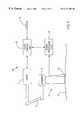
- FIG. 1is a schematic block diagram illustrating a system for controlling the exposure of a surface of a tissue to laser radiation in accordance with a preferred embodiment of the present invention
- FIG. 2is a schematic block diagram illustrating a system for controlling the exposure of a surface of a tissue to laser radiation in accordance with another preferred embodiment of the present invention
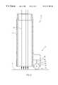
- FIG. 3is a schematic longitudinal cross section illustrating the handpiece of FIG. 1 in detail, in accordance with a preferred embodiment of the present invention
- FIG. 4is a schematic cross section illustrating a handpiece constructed and operative in accordance with another preferred embodiment of the present invention.
- FIG. 5is a schematic cross section illustrating a handpiece using a laser beam delivered by an optical fiber, constructed and operative in accordance with yet another preferred embodiment of the present invention
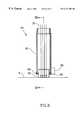
- FIG. 6is a schematic cross section illustrating a handpiece having a transparent rotatable member in accordance with another preferred embodiment of the present invention.
- FIG. 7is a cross section of the handpiece of FIG. 6 taken along the lines VII—VII;
- FIG. 8is a schematic cross section illustrating a handpiece having a rotatable member with an octagonal cross section in accordance with another preferred embodiment of the present invention.
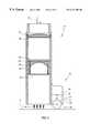
- FIG. 9is a schematic cross section illustrating a handpiece constructed and operative to control the exposure of a surface of a tissue to laser radiation and to cool the tissue in accordance with still another preferred embodiment of the present invention.
- FIG. 10is a schematic cross sections illustrating a handpiece for controlling the exposure of a surface of a tissue to laser radiation and for marking the surface with a marker in accordance with another preferred embodiment of the present invention
- FIG. 11is a schematic cross section of a different view of the handpiece of FIG. 10
- FIG. 12is a schematic cross section illustrating a handpiece constructed and operative to control the exposure of a surface of a tissue to laser radiation and to mark the surface with a marker in accordance with still another preferred embodiment of the present invention
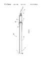
- FIG. 13is a schematic isometric view of the handpiece of FIG. 12;
- FIG. 14is a schematic cross section illustrating a handpiece having a multi-directional sensor enabling controlling the exposure of a surface of a tissue to laser radiation while the handpiece is being moved in any orientation along the surface of the tissue, in accordance with another preferred embodiment of the present invention.
- FIG. 15is a schematic cross section illustrating a handpiece having a multi-directional sensor enabling controlling the exposure of a surface of a tissue to laser radiation while the handpiece is being moved in any orientation along the surface of the tissue and for marking the surface with a marker, in accordance with still another preferred embodiment of the present invention.
- FIG. 1is a schematic block diagram illustrating a system 10 for controlling the exposure of a surface of a tissue to laser radiation in accordance with a preferred embodiment of the present invention.
- System 10includes a laser 2 connected to a handpiece 4 by a suitable beam delivery system 12 .
- the beam delivery system 12can be any suitable delivery system such as an optical fiber, an optical fiber bundle or a suitable waveguide such as the hollow waveguide disclosed in U.S. Pat. No. 5,325,458 to Morrow et al.
- the handpiece 4includes a hollow member 5 enabling the laser light to pass within it and strike the surface 6 of the tissue that is to be irradiated.
- the handpiece 4can also include optical elements (not shown) for suitably directing the laser light beam onto the surface 6 . These optical elements are constructed to direct a laser light spot at the surface 6 , the spot having a desired size and shape suitable for the specific therapeutic or cosmetic application.
- the handpiece 4also includes a sensor assembly 16 attached to the hollow member 5 for sensing the translation of the handpiece along the surface 6 .
- the sensor assemblycan include any type of sensor suitable for generating signals which can be used to determine the distance traversed by the handpiece 4 on the surface 6 , such as a mechanical or an optical encoder as disclosed in detail hereinafter.
- the system 10also includes a signal processor 14 suitably connected to the sensor assembly 16 and laser control unit 8 connected to the signal processor 14 and to the laser 2 .
- the system 10also includes an actuating switch 18 which can be any suitable switch such as a foot pedal. When the actuating switch 18 is depressed by the operator, the laser 2 can be activated by the laser control unit 8 . Thus, activating the laser is enabled as long as the actuating switch is held depressed by the operator. The actuating switch thus serves as a safety measure against accidental activation of the laser.
- the sensor assembly 16senses the translational movements of the handpiece 4 and sends suitable signals to the signal processor 14 .
- the signal processor 14processes the signals of the sensor assembly 16 and calculates the distance traversed by the handpiece from the last position at which the laser was activated.
- the operatorputs the handpiece 4 on the surface 6 and depresses the actuating switch 18 to activate the laser and irradiate the area underneath the handpiece.
- the operatorcan be assisted by a low power indicating light beam (not shown) to view the area which will be irradiated before activating the laser.
- the operatorcan observe the indicating light through suitable openings (not shown) in the hollow member 5 .
- the operatorthen moves the handpiece on the surface 6 .
- the sensor assembly 16sends signals to the signal processor which calculates the distance traversed by the handpiece on the surface 6 .
- the signal processoralso calculates the required distance to the next desirable area for irradiation by taking into account the dimensions of the irradiated spot and the degree of the overlap of two adjacent irradiated spots required to achieve a substantially uniform exposure to the radiation.
- This overlapcan be necessary when the irradiating energy is non-uniformly distributed within the irradiated spot.
- the energy densitycan have a gaussian distribution profile along the diameter of a circular irradiated spot.
- the signal processoralerts the operator by issuing a stop signal.
- the stop signalcan be a suitable sound such as a beep tone or a visual signal such as the lighting up of an indicator light or a combination of a sound and a visual signal.
- the stop signalindicates to the operator that the handpiece has reached the next area to be irradiated. If the laser is ready for activation, the system automatically activates the laser. Once the laser is activated, the stop signal is turned off and the user can continue to move the handpiece 4 , repeating the sequence of steps described hereinabove, thus exposing consecutive areas of the tissue surface.
- This methodis suitable for pulsed lasers having a low pulsing frequency, such as a ruby laser.
- the stop signalinstructs the operator to stop moving the handpiece until the laser is ready for delivering another pulse. It is noted that, if a laser having a higher pulse frequency is used with the system 10 , the stop signal is rendered unnecessary since the laser will be capable of automatically delivering a pulse each time the handpiece traverses a distance equal to the calculated optimal distance between two irradiated spots.
- the operatorcan move the handpiece 4 while the laser is being automatically activated by the signal processor to irradiate a portion of the surface 6 such as a substantially linear stripe or any other suitable portion of the surface 6 .
- the operatorcan reposition the handpiece 4 at a new position on the surface 6 and proceed to similarly irradiate another portion of the surface 6 , such as a new substantially linear stripe parallel to the previously irradiated first line.
- the operatorcan achieve a substantially complete irradiation of the tissue surface 6 , while avoiding serious overexposure of surface areas, by repeating the above procedure until the desired area of the surface 6 is satisfactorily treated.
- the method disclosed hereinaboveuses a pulsed laser
- the methodcan also be used with a continuous wave laser.
- the continuous wave lasercan be activated for relatively brief periods of continuous operation. It is further noted that, the periods of continuous operation of the continuous wave laser can be substantially longer than the typical pulse duration of pulsed lasers such as ruby lasers.
- FIG. 2is a schematic block diagram illustrating a system 50 for controlling the exposure of a surface of a tissue to laser radiation in accordance with another preferred embodiment of the present invention.
- System 50is similar to system 10 of FIG. 1 except that laser 2 , beam delivery system 12 and handpiece 4 of FIG. 1 are replaced by a laser 3 , an articulated arm delivery system 7 , a scanner 9 and a handpiece 34 .
- Handpiece 34operates similarly to handpiece 4 of FIG. 1 to control the exposure of the surface 6 to laser radiation as disclosed hereinabove, except that it is attached to the scanner 9 .
- the lasercreates a spot of laser light on surface 6
- the system 50 of FIG. 2scans a laser beam along a defined area of surface 6 which underlies handpiece 34 .
- the sensor assembly 16also includes an optical sensor 28 detachably attached to the housing 21 .
- the optical sensorcan be any suitable optical sensor such as the reflective object sensor model OPB 706A commercially available from Optek Technology, Inc. TX, U.S.A., that includes an infra-red light source and a light detector (not shown).
- the optical sensor 28can be detached from the housing 21 so that the handpiece 4 can be sterilized.
- the optical sensor 28radiates an infrared light beam 30 that hits the surface of the rotatable member 22 underlying it and is reflected therefrom to reach the light detector of the optical sensor 28 . If the light beam is reflected from one of the areas 24 , the intensity of the reflected light is sufficient to activate the optical sensor 28 to send an “on” signal to the signal processor unit 8 . If the light beam is reflected from the surface at the bottom of one of the notches 26 , the intensity of the light reflected from that bottom surface is not sufficient to activate the optical sensor 28 , and the optical sensor 28 sends an “off” signal to the signal processor unit 8 .
- the signal processing unit 8uses the on and off signals, which are represented by different predetermined voltage values, to calculate the distance traversed by the handpiece 4 on the surface 6 and to determine the next location for firing the laser 2 as disclosed in detail hereinabove.
- rotatable member 22 of the preferred embodiment of FIG. 3is cogwheel shaped
- other rotatable memberscan be used such as a rotatable member having a circular or polygonal cross section or any other rotatable member that can be rolled along the surface 6 without substantial slip and that has on its surface alternating areas having suitably different reflectivity values that can be differentiated by the optical sensor 28 .
- a non limiting exampleis a rotatable member having alternating rough and smooth areas which have substantially different reflectivity values at the wavelength of light used by the optical sensor 28 .
- Another non limiting exampleis a rotatable member made of a highly reflective metal and having equally spaced stripes of a plastic having low reflectivity embedded therein.
- the rotatable member 22can be made from a sterilizable material such as a metal.
- rotatable member 22is made from aluminum.
- Rotatable member 22is detachably attached to the housing 21 and can be detached therefrom. This facilitates the sterilization of rotatable member 22 .
- rotatable member 22can be disposable and can be replaced before using the handpiece 4 for treating a new patient.
- FIG. 4is a schematic cross section illustrating a handpiece 44 , constructed and operative in accordance with another preferred embodiment of the present invention.
- Handpiece 44can be used instead of handpiece 4 in system 10 of FIG. 1 .
- Handpiece 44includes a hollow member 35 and a sensor assembly 16 attached thereto. The sensor assembly 16 is constructed and operative in determining the distance traversed by handpiece 44 along surface 6 as disclosed hereinabove.
- Handpiece 44further includes an upper lens 38 secured within the hollow member 35 by a lens holder 40 .
- Handpiece 44also includes a lower lens 45 secured within the hollow member 35 by a lens holder 42 .
- Handpiece 44further includes a protective window 48 and a spacer 46 disposed between the lower lens 45 and the protective window 48 . Lenses 38 and 45 modify the incoming laser beam 52 so that the outgoing laser beam 54 has the appropriate energy density required for treatment of surface 6 .
- FIG. 5is a schematic cross section illustrating a handpiece 64 , using a laser beam delivered by an optical fiber, constructed and operative in accordance with yet another preferred embodiment of the present invention.
- Handpiece 64can be used instead of handpiece 4 in system 10 of FIG. 1 .
- Handpiece 64includes an applicator 65 and a sensor assembly 16 attached thereto. The sensor assembly 16 is constructed and operative in determining the distance traversed by handpiece 64 along surface 6 as disclosed hereinabove.
- Handpiece 64also includes a fiber adapter 70 attached to applicator 65 .
- Fiber adapter 70further includes an optical fiber 72 for guiding a laser beam from laser source 2 of FIG. 1 into the handpiece 64 .
- Optical fiber 72is connected to the fiber adapter 70 by fiber connector 74 .
- Fiber adapter 70further includes a lens 66 secured within the fiber adapter 70 by a lens holder 68 .
- Fiber adapteralso includes a protective window 76 for protecting the lens 66 .
- Lens 66modifies the laser beam exiting from optical fiber 72 so that it has the appropriate energy density required for treatment of surface 6 .
- FIG. 6is a schematic cross section illustrating a handpiece 84 constructed and operative to control the exposure of a surface of a tissue to laser radiation in accordance with still another preferred embodiment of the present invention.
- Handpiece 84includes a hollow member 85 and a rotatable member 82 rotatably attached to hollow member 85 by two axles 88 and 89 .
- Axle 89is also connected to a sensor 86 for sensing the distance traversed by the rotatable member 82 along surface 6 .
- the sensor 86can be any suitable sensor such an electro-optical sensor or a hall effect sensor for sensing the rotation of axle 89 and encoding the rotation into appropriate signals.
- the signals from sensor 86are sent to a suitable signal processor unit such as the signal processor unit 8 of FIG. 1 for calculating the distance traversed by the handpiece 84 , taking into account the diameter of the rotatable member 82 , as disclosed hereinabove.
- the rotatable member 82is made of a material that is substantially transparent to the wavelength of light beam 20 such as suitable transparent plastic or suitable glass.
- the laser light 20thus passes through rotatable member 82 to strike an area of surface 6 underlying rotatable member 82 .
- FIG. 7is a cross section of handpiece 84 of FIG. 6, taken along the lines VII—VII.
- FIG. 8illustrating a schematic cross section of a handpiece 94 in accordance with another preferred embodiment of the present invention.
- Handpiece 94is similar to handpiece 84 of FIGS. 6 and 7, except that it includes a transparent rotatable member 92 having an octagonal cross section in contrast to the rotatable member 82 of handpiece 84 which has a circular cross section (FIG. 7 ).
- This preferred embodimenthas an advantage of diminishing the distortion of the laser beam 20 as it passes through the transparent rotatable member.
- the transparent rotatable member 82 of handpiece 84can have any other suitable cross section and can be made of any suitable material which is substantially transparent to the light beam 20 .
- FIG. 9is a schematic cross section illustrating a handpiece 104 constructed and operative to control the exposure of a surface of a tissue to laser radiation and to cool the tissue in accordance with still another preferred embodiment of the present invention.
- Handpiece 104includes a hollow member 105 having a rotatable member 102 rotatably attached thereto.
- Rotatable member 102is hollow and can rotate within the hollow member 105 on two hollow axles 107 .
- Each of the hollow axles 107is connected to a flexible tube 108 by a leak-proof rotating connector 110 .
- the hollow rotatable member 102is filled with a cooling fluid 112 which is pumped through the hollow rotatable member 102 by a suitable pump (not shown) through one of the flexible tubes 108 and leaves the hollow rotatable member 102 through the other flexible tube 108 .
- a suitable pumpnot shown
- the hollow rotatable member 102rolls along surface 6 and cools the tissue underlying it.
- the hollow rotatable member 102 and the cooling fluid 112are substantially transparent to the laser beam 20 which passes through them to strike the underlying surface 6 .
- An advantage of this preferred embodiment of the present inventionis that the cooling of the tissue decreases the heat load of the irradiated tissue and lowers the maximal temperature to which the irradiated tissue is exposed, thus avoiding burns to the upper layers of the tissue during the irradiation treatment.
- the Handpiece 104also includes a sensor 116 which senses the movement of the hollow rotatable member 102 as it rolls along surface 6 .
- Sensor 116can be any suitable type of sensor.
- a non-limiting exampleis the optical sensor such as the reflective object sensor model OPB 706A disclosed hereinabove ( FIG. 3 ).
- Sensor 116can operate by sensing the reflectivity of areas on the surface of hollow rotatable member 102 having alternating high and low reflectivity values (The alternating areas are not shown in FIG. 9 for the sake of clarity of illustration). These alternating areas face the detector (not shown) of sensor 116 .
- hollow rotatable member 102 of handpiece 104can have any suitable cross section such as a circular or a polygonal cross section.
- cooling fluid 112can be any suitable cooling fluid such as water, a suitable salt solution, an solution of glycerol in water or any other cooling fluid which is substantially transparent to the laser beam 20 .
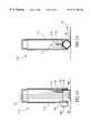
- FIGS. 10 and 11are schematic cross sections illustrating a handpiece 114 constructed and operative to control the exposure of a surface of a tissue to laser radiation and to mark the surface with a marker in accordance with another preferred embodiment of the present invention.
- Handpiece 114includes a hollow member 115 having a rotatable member 82 rotatably attached thereto.
- Rotatable member 82is connected to a sensor 86 and operates in sensing the distance traversed by the handpiece 114 as disclosed in detail for handpiece 84 of FIG. 6 hereinabove.
- Hollow member 115also includes a marking device 117 (FIG. 11) for marking the surface 6 with a visible marker.
- Marking device 117includes a replaceable container 119 containing a marker 116 therewithin.
- Marker 116can be any marking fluid suitable for leaving a visible trace upon surface 6 of the tissue.
- Marking device 117further includes a marking tip 120 which is in contact with rotatable member 82 . When handpiece 114 is moved along surface 6 , marking tip 120 transfers some of marker 116 onto the surface of rotatable member 82 , thus, depositing a marker film 118 on rotatable member 82 .
- Visible marker trace 122has the advantage of providing the operator of handpiece 114 with a visible mark assisting the operator in observing the areas of the surface 6 which have been irradiated, thus helping in preventing accidental over-exposure of areas which have been already irradiated.
- a further advantage of visible marker trace 122is that it assists the operator of handpiece 114 in obtaining a relatively uniform exposure of the area to be treated by providing a visible track parallel to which the operator can align the movement of handpiece 114 for irradiating the next part of surface 6 .
- the marking device 117can be any suitable marking device such as a replaceable cartridge a refillable cartridge or any other marking device capable of suitably transferring marker 116 to surface 6 .
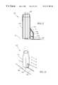
- FIG. 12is a schematic cross section illustrating a handpiece 124 constructed and operative to control the exposure of a surface of a tissue to laser radiation and to mark the surface with a marker in accordance with still another preferred embodiment of the present invention
- FIG. 13is a schematic isometric view of the handpiece 124 of FIG. 12 .
- Handpiece 124includes a hollow member 125 having a housing 121 attached thereto.
- Housing 121includes a rotatable member 132 rotatably attached thereto.
- Rotatable member 132is connected to a sensor (not shown for the sake of clarity of illustration) and operates in sensing the distance traversed by the handpiece 114 as disclosed in detail for handpiece 84 of FIG. 6 hereinabove.
- Housing 121also includes a marking device 127 for marking the surface 6 with a visible marker.
- Marking device 127includes a replaceable container 129 containing a marker 126 therewithin.
- Marking device 127further includes a marking tip 128 which is in contact with rotatable member 132 .
- marking tip 128transfers some of marker 126 onto the surface of rotatable member 132 , thus, depositing a marker film (not shown) thereon.
- part of the marker 126 of the marker filmis transferred from rotatable member 132 to surface 6 , creating a visible marker trace 134 therealong.
- FIG. 13illustrates the handpiece 124 of FIG. 12 being moved along the skin surface 140 of a hand.
- the handpiece 124is moved along the skin surface 140 in the direction of the arrows labeled A. also shown is the visible marker trace 134 which is left on the skin surface 140 by the handpiece 124 .
- the handpieces 4 , 44 , 64 , 84 , 94 , 104 , 114 , and 124 of FIGS. 3, 4 , 5 , 6 , 8 , 9 , 10 and 12 , respectively,are designed to be oriented in a specific direction while being moved along the surface 6 .
- This orientationis determined by the preferred direction of rotation of the rotatable member of the handpiece.
- the handpiece 4 of FIG. 3has to be oriented such that the axis around which the rotatable member 22 rotates is perpendicular to the direction along which the handpiece 4 is moved.
- the handpiece 114 of FIG. 10has to be oriented such that the axis around which the rotatable member 82 rotates is perpendicular to the direction along which the handpiece 114 is moved.
- visibly discernible “landmarks” existing on the handpiececan be used for proper orientation. This is best seen in FIG. 13 where the housing 121 protrudes from the handpiece 124 , thus, indicating the required orientation of movement labeled by arrows A. In handpieces having no visibly discernible landmarks, such landmarks can be added. In accordance with one embodiment of the present invention, a stripe of color can be painted on the outer surface of the handpiece (not shown) to indicate the required orientation.
- the handpiececan be shaped such that it has a distinctly discernible polarity indicating the required orientation.
- at least part of the hollow member 85 of handpiece 84can have a “teardrop” like cross-section (not shown) with the pointed part thereof indicating the required orientation for moving the handpiece 84 along the surface 6 .
- FIG. 14is a schematic cross section illustrating a handpiece 154 having a multi-directional sensor constructed and operative in accordance with another preferred embodiment of the present invention to control the exposure of a surface of a tissue to laser radiation while being moved in any orientation of the handle along the surface of the tissue.
- FIG. 15is a schematic cross section illustrating a handpiece 194 having a multi-directional sensor for controlling the exposure of a surface of a tissue to laser radiation while being moved in any orientation of the handle along the surface of the tissue and for marking the surface with a marker, in accordance with still another preferred embodiment of the present invention.
- the handpiece 154includes a hollow member 155 , and a sensor assembly 166 attached to one end of the hollow member 155 .
- the sensor assembly 166includes a housing 171 and a spherical rotatable member 172 .
- the spherical rotatable member 172is suitably attached within the housing 171 such that it can freely rotate in any selected direction.
- the handpiece 154can be moved in any selected direction along the surface 6 , causing the spherical rotatable member 172 to rotate within the housing 171 .
- the sensor assembly 166also includes an optical sensor 28 which operates as disclosed hereinabove for the handpiece 4 of FIG. 3 .
- the spherical rotatable member 172is made of a suitable material such as metal or plastic.
- the spherical rotatable member 172has a plurality of circular spots 175 painted or attached on its surface.
- the spots 175have a light reflectivity which is substantially different than the reflectivity of the surface of the spherical member between the spots 175 .
- the reflectivity of the spots 175can be higher than the reflectivity of surface of the spherical member between the spots, mutatis mutandis.
- a feature of the sensor assembly 166is that the spots 175 are isotropically distributed along the surface of the spherical rotatable member 172 in such a way that the average number of transitions between areas of different reflectivity values occurring per unit length when moving in any randomly selected direction along the surface of the rotatable spherical member 172 is constant irrespective of the direction of movement.
- the sensor 28illuminates the surface of the spherical rotatable member 172 with a light beam 168 and detects the changes in reflectivity occurring as the spots pass under the light beam 168 as disclosed hereinabove for the notches of the cogwheel shaped rotatable member 22 of sensor assembly 16 of FIG. 3 .
- the sensor 28thus sends “on” and “off” signals to the signal processor unit 14 (FIG. 1) through a suitable connecting cable (not shown) for calculating the distance traversed by the handpiece 154 on the surface 6 , based on the known distribution of the spots 175 on the surface of the rotatable spherical member 172 .
- the spherical rotatable member 172can have notches or depressions within its surface (not shown) having a different reflectivity than the surface between the notches. Such notches will function similarly to the spots 175 .
- spots 175 or the notches disclosed hereinaboveare preferably circular but can also have other suitable shapes as long as they are isotropically distributed along the surface and as long as their size is relatively small compared to the diameter of the spherical rotatable member 172 .
- the handpiece 154can thus be moved along the surface 6 in any selected direction, while the longitudinal axis of the handpiece 154 along which axis the beams 180 are directed is substantially perpendicular to the surface 6 , without the handpiece having to be oriented in a specific direction, while still maintaining a controlled exposure of the surface to light beams 180 as disclosed hereinabove.
- the sensor assembly 166 of the handpiece 154is of FIG. 14 is implemented as a particular type of optical sensor, the sensor assembly 166 can be any suitable type of sensor such as an optical sensor or a suitable mechanical sensor that can sense the movement of the handpiece 154 along the surface 6 , irrespective of the direction of movement selected.
- Handpiece 194includes a hollow member 195 having a spherical rotatable member 192 suitably attached thereto such that spherical rotatable member 192 is freely rotatable in any selected direction.
- the spherical rotatable member 192is made of a material which is transparent to the radiation which is irradiated from the radiation source which is connected to the handpiece such as a laser beam irradiated from a laser.
- the spherical rotatable member 192can be made from glass or transparent plastic depending on the particular wavelengths of the radiation radiated from the radiation source.
- the handpiece 194further includes a sensor assembly 196 suitably attached to the hollow member 195 .
- the sensor assembly 196includes a housing 199 , a spherical rotatable member 200 and an optical sensor 198 .
- the spherical rotatable member 200has a plurality of spots or notches 205 formed on its surface, similarly to the spots or notches 175 of the spherical rotatable member 172 of FIG. 14 .
- the spots or notches 205are isotropically distributed along the surface of the spherical rotatable member 200 .
- the spherical rotatable membercan be made of a slightly resilient material such as rubber or plastic and is spring loaded by a spring 204 so that it is pressed against the surface of the spherical rotatable member 192 .
- the spherical rotatable member 192When the spherical rotatable member 192 is placed in contact with the surface 6 and the handpiece 194 is moved along the surface 6 , the spherical rotatable member 192 rotates causing the spherical rotatable member 200 to rotate.
- the sensing of the movement of the spherical rotatable member 200 by theis done similarly to the sensing of the movement of the spherical rotatable member 172 by optical sensor 198 as disclosed for sensor 28 of FIG. 15 .
- the sensor 198thus sends “on” and “off” signals to the signal processor unit 14 (FIG.
- the handpiece 194can thus be moved along the surface 6 in any selected direction, without the handpiece having to be oriented in a specific direction, while still maintaining a controlled exposure of the surface to light beams 220 , as disclosed hereinabove.
- the handpiece 194also includes a marking device 202 .
- Marking device 202includes a replaceable container 201 containing a marker 203 therewithin.
- Marking device 202further includes a marking tip 206 which is in contact with the surface 6 when the hand piece 194 is placed in contact therewith.
- the marking tip 206transfers some of the marker 203 onto the surface 6 , thus, depositing a visible marker film (not shown) thereupon.
- the visible marker filmassists the operator in determining which areas of the surface 6 have already been exposed to radiation.
- the path of the beamsmay be distorted (not shown) when the beams pass through the transparent rotatable members 82 , 102 and 192 , which may also cause a change in the shape and size of the spot of light which is projected on the surface 6 . (the distortion of the beams is not shown in any of the FIGS. 6, 9 , 10 , 11 and 15 for the sake of clarity of illustration).
- a common feature of all the preferred embodiments of the handpiece of the present invention disclosed hereinaboveis that, in all of them the handpiece can be used by first coating the surface of the tissue with a layer of a gel such as the ultrasound gel “Aquasonic clear” commercially available as product No. 0308 from Parker Laboratories, N.J., U.S.A., which is substantially transparent to the laser beam 20 , and proceeding to operate the handpiece to irradiate the surface of the tissue as disclosed hereinabove for each of the different handpieces.
- the use of gelhas the advantage of assisting in the cooling of the tissue which results in the same advantages as disclosed for handpiece 104 hereinabove.
- the laser used with the systemis a pulsed laser.
- the laser used with the handpieceis a continuous wave laser.
Landscapes
- Physics & Mathematics (AREA)
- Health & Medical Sciences (AREA)
- Surgery (AREA)
- Optics & Photonics (AREA)
- Life Sciences & Earth Sciences (AREA)
- Engineering & Computer Science (AREA)
- Otolaryngology (AREA)
- Nuclear Medicine, Radiotherapy & Molecular Imaging (AREA)
- Electromagnetism (AREA)
- Biomedical Technology (AREA)
- Heart & Thoracic Surgery (AREA)
- Medical Informatics (AREA)
- Molecular Biology (AREA)
- Animal Behavior & Ethology (AREA)
- General Health & Medical Sciences (AREA)
- Public Health (AREA)
- Veterinary Medicine (AREA)
- Laser Surgery Devices (AREA)
Abstract
Description
Claims (35)
Priority Applications (1)
| Application Number | Priority Date | Filing Date | Title |
|---|---|---|---|
| US09/040,721US6171302B1 (en) | 1997-03-19 | 1998-03-18 | Apparatus and method including a handpiece for synchronizing the pulsing of a light source |
Applications Claiming Priority (2)
| Application Number | Priority Date | Filing Date | Title |
|---|---|---|---|
| US4131297P | 1997-03-19 | 1997-03-19 | |
| US09/040,721US6171302B1 (en) | 1997-03-19 | 1998-03-18 | Apparatus and method including a handpiece for synchronizing the pulsing of a light source |
Publications (1)
| Publication Number | Publication Date |
|---|---|
| US6171302B1true US6171302B1 (en) | 2001-01-09 |
Family
ID=26717341
Family Applications (1)
| Application Number | Title | Priority Date | Filing Date |
|---|---|---|---|
| US09/040,721Expired - LifetimeUS6171302B1 (en) | 1997-03-19 | 1998-03-18 | Apparatus and method including a handpiece for synchronizing the pulsing of a light source |
Country Status (1)
| Country | Link |
|---|---|
| US (1) | US6171302B1 (en) |
Cited By (75)
| Publication number | Priority date | Publication date | Assignee | Title |
|---|---|---|---|---|
| US6446350B1 (en)* | 1998-12-11 | 2002-09-10 | Johannes Heidenhain Gmbh | Method and arrangement for reducing temperature-related dimensional discrepancies in measurement systems arranged in parallel |
| US20030216719A1 (en)* | 2001-12-12 | 2003-11-20 | Len Debenedictis | Method and apparatus for treating skin using patterns of optical energy |
| EP1226787A3 (en)* | 2001-01-29 | 2003-12-17 | Laserwave S.r.l. | Device for cutaneous treatments using optical radiation |
| US6758845B1 (en) | 1999-10-08 | 2004-07-06 | Lumenis Inc. | Automatic firing apparatus and methods for laser skin treatment over large areas |
| US20050045189A1 (en)* | 2003-08-26 | 2005-03-03 | Harvey Jay | Skin treatment with optical radiation |
| US20050049582A1 (en)* | 2001-12-12 | 2005-03-03 | Debenedictis Leonard C. | Method and apparatus for fractional photo therapy of skin |
| US20050141068A1 (en)* | 2003-12-31 | 2005-06-30 | Debenedictis Leonard C. | High speed, high efficiency optical pattern generator using rotating optical elements |
| US20050143719A1 (en)* | 2003-12-31 | 2005-06-30 | Sink Robert K. | Multi-spot laser surgical apparatus and method |
| US20050154380A1 (en)* | 2003-12-23 | 2005-07-14 | Debenedictis Leonard C. | Method and apparatus for monitoring and controlling laser-induced tissue treatment |
| US20050259306A1 (en)* | 2003-12-31 | 2005-11-24 | Broome Barry G | Two-dimensional optical scan system using a counter-rotating disk scanner |
| US20050278002A1 (en)* | 2004-06-14 | 2005-12-15 | David Eimerl | Adaptive control of optical pulses for laser medicine |
| US20060004347A1 (en)* | 2000-12-28 | 2006-01-05 | Palomar Medical Technologies, Inc. | Methods and products for producing lattices of EMR-treated islets in tissues, and uses therefor |
| US20060122668A1 (en)* | 2000-12-28 | 2006-06-08 | Palomar Medical Technologies, Inc. | Method and apparatus for EMR treatment |
| US20060155266A1 (en)* | 2003-03-27 | 2006-07-13 | Dieter Manstein | Method and apparatus for dermatological treatment and fractional skin resurfacing |
| US7083610B1 (en)* | 2000-06-07 | 2006-08-01 | Laserscope | Device for irradiating tissue |
| US20060200115A1 (en)* | 2005-03-04 | 2006-09-07 | Searete Llc., A Limited Liability Corporation Of The State Of Delaware | Hair treatment system |
| US20060200114A1 (en)* | 2005-03-04 | 2006-09-07 | Searete Llc, A Limited Liability Corporation Of State Of Delaware | Hair removal system with light source array |
| US20060197247A1 (en)* | 1998-02-12 | 2006-09-07 | Moldflow Pty Ltd | Automated Molding Technology For Thermoplastic Injection Molding |
| US20060200116A1 (en)* | 2005-03-04 | 2006-09-07 | Searete Llc, A Limited Liability Corporation Of The State Of Delaware | Method and system for temporary hair removal |
| US20060276860A1 (en)* | 2005-06-02 | 2006-12-07 | Searete Llc, A Limited Liability Corporation Of The State Of Delaware | Skin treatment including patterned light |
| US20060276859A1 (en)* | 2005-06-02 | 2006-12-07 | Searete Llc, A Limited Liability Corporation Of The State Of Delaware | Photopatterning of skin |
| US20070005047A1 (en)* | 2005-06-29 | 2007-01-04 | Searete Llc, A Limited Liability Corporation | Hair modification using converging light |
| US20070027440A1 (en)* | 2001-03-02 | 2007-02-01 | Palomar Medical Technologies, Inc. | Apparatus and method for photocosmetic and photodermatological treatment |
| US20070032846A1 (en)* | 2005-08-05 | 2007-02-08 | Bran Ferren | Holographic tattoo |
| US20070038270A1 (en)* | 2005-07-05 | 2007-02-15 | Searete Llc, A Limited Liability Corporation Of The State Of Delaware | Multi step photopatterning of skin |
| US20070049910A1 (en)* | 2005-08-08 | 2007-03-01 | Palomar Medical Technologies, Inc. | Eye-safe photocosmetic device |
| US20070048340A1 (en)* | 2005-08-31 | 2007-03-01 | Searete Llc, A Limited Liability Corporation Of The State Of Delaware | Multi step patterning of a skin surface |
| US20070060819A1 (en)* | 2005-09-15 | 2007-03-15 | Palomar Medical Technologies, Inc. | Skin optical characterization device |
| US20070093798A1 (en)* | 2005-08-29 | 2007-04-26 | Reliant Technologies, Inc. | Method and Apparatus for Monitoring and Controlling Thermally Induced Tissue Treatment |
| US20070179481A1 (en)* | 2003-02-14 | 2007-08-02 | Reliant Technologies, Inc. | Laser System for Treatment of Skin Laxity |
| US20070213792A1 (en)* | 2002-10-07 | 2007-09-13 | Palomar Medical Technologies, Inc. | Treatment Of Tissue Volume With Radiant Energy |
| US20070217199A1 (en)* | 2006-03-17 | 2007-09-20 | Light Dimensions, Inc. | Light-based dermal enhancing apparatus and methods of use |
| US20070260230A1 (en)* | 2006-05-04 | 2007-11-08 | Reliant Technologies, Inc. | Opto-mechanical Apparatus and Method for Dermatological Treatment |
| US20080033516A1 (en)* | 2002-10-07 | 2008-02-07 | Palomar Medical Technologies, Inc. | Methods and apparatus for performing photobiostimulation |
| US20080058782A1 (en)* | 2006-08-29 | 2008-03-06 | Reliant Technologies, Inc. | Method and apparatus for monitoring and controlling density of fractional tissue treatments |
| US20080103565A1 (en)* | 2002-06-19 | 2008-05-01 | Palomar Medical Technologies, Inc. | Method and apparatus for treatment of cutaneous and subcutaneous conditions |
| US20080132886A1 (en)* | 2004-04-09 | 2008-06-05 | Palomar Medical Technologies, Inc. | Use of fractional emr technology on incisions and internal tissues |
| US20080154157A1 (en)* | 2006-12-13 | 2008-06-26 | Palomar Medical Technologies, Inc. | Cosmetic and biomedical applications of ultrasonic energy and methods of generation thereof |
| US20080161745A1 (en)* | 2006-09-08 | 2008-07-03 | Oliver Stumpp | Bleaching of contrast enhancing agent applied to skin for use with a dermatological treatment system |
| US20080161782A1 (en)* | 2006-10-26 | 2008-07-03 | Reliant Technologies, Inc. | Micropore delivery of active substances |
| US20080188839A1 (en)* | 2007-02-06 | 2008-08-07 | Reliant Technologies, Inc. | Method and apparatus for monitoring and controlling laser-induced tissue treatment |
| US20080262484A1 (en)* | 2007-04-23 | 2008-10-23 | Nlight Photonics Corporation | Motion-controlled laser surface treatment apparatus |
| US20080294153A1 (en)* | 1996-12-02 | 2008-11-27 | Palomar Medical Technologies, Inc. | Cooling System For A Photocosmetic Device |
| US20080294151A1 (en)* | 2007-05-23 | 2008-11-27 | Reliant Technologies, Inc. | Pivoting Roller Tip for Dermatological Treatment Apparatus |
| US20090012511A1 (en)* | 2007-06-08 | 2009-01-08 | Cynosure, Inc. | Surgical waveguide |
| WO2009037641A1 (en)* | 2007-09-21 | 2009-03-26 | Koninklijke Philips Electronics N.V. | Skin treatment device with means for providing a tactile feedback signal |
| US20090118720A1 (en)* | 2001-12-12 | 2009-05-07 | Reliant Technologies, Inc. | Dermatological Apparatus and Method |
| US20090292277A1 (en)* | 2006-08-02 | 2009-11-26 | Cynosure, Inc. | Picosecond laser apparatus and methods for its operation and use |
| US20100204686A1 (en)* | 2002-12-20 | 2010-08-12 | Palomar Medical Technologies, Inc. | Light treatments for acne and other disorders of follicles |
| US7935107B2 (en) | 1997-05-15 | 2011-05-03 | Palomar Medical Technologies, Inc. | Heads for dermatology treatment |
| US7942916B2 (en) | 2002-05-23 | 2011-05-17 | Palomar Medical Technologies, Inc. | Phototreatment device for use with coolants and topical substances |
| USRE42594E1 (en) | 1998-10-16 | 2011-08-02 | Reliant Technologies, Inc. | Tissue cooling rod for laser surgery |
| US8002768B1 (en) | 1997-05-15 | 2011-08-23 | Palomar Medical Technologies, Inc. | Light energy delivery head |
| US8182473B2 (en) | 1999-01-08 | 2012-05-22 | Palomar Medical Technologies | Cooling system for a photocosmetic device |
| GB2486919A (en)* | 2010-12-31 | 2012-07-04 | Alma Lasers Ltd | Dermatological light treatment device with distance measurement and trigger |
| WO2012106687A1 (en)* | 2011-02-03 | 2012-08-09 | Tria Beauty, Inc. | Radiation-based dermatological devices and methods |
| US20120283803A1 (en)* | 2011-02-03 | 2012-11-08 | TRIA Beauty | Devices and Methods for Radiation-Based Dermatological Treatments |
| US8328794B2 (en) | 1996-12-02 | 2012-12-11 | Palomar Medical Technologies, Inc. | System for electromagnetic radiation dermatology and head for use therewith |
| US8529560B2 (en) | 2005-03-04 | 2013-09-10 | The Invention Science Fund I, Llc | Hair treatment system |
| US20130237973A1 (en)* | 2012-03-09 | 2013-09-12 | Snu R&Db Foundation | Laser emission system and robot laser emission device comprising the same |
| US8679102B2 (en) | 2011-02-03 | 2014-03-25 | Tria Beauty, Inc. | Devices and methods for radiation-based dermatological treatments |
| US8685008B2 (en) | 2011-02-03 | 2014-04-01 | Tria Beauty, Inc. | Devices and methods for radiation-based dermatological treatments |
| ITRM20120489A1 (en)* | 2012-10-15 | 2014-04-16 | Piero Tesauro | PATENT OF INVENTION FROM THE "ROLLER MEASURER STAMP" TITLE |
| EP2732786A1 (en)* | 2012-11-19 | 2014-05-21 | Seb S.A. | Skin treatment apparatus provided with a guiding means |
| EP3058862A4 (en)* | 2013-10-15 | 2017-06-21 | Olympus Corporation | Medical device |
| US9780518B2 (en) | 2012-04-18 | 2017-10-03 | Cynosure, Inc. | Picosecond laser apparatus and methods for treating target tissues with same |
| US9789332B2 (en) | 2011-02-03 | 2017-10-17 | Tria Beauty, Inc. | Devices and methods for radiation-based dermatological treatments |
| US9919168B2 (en) | 2009-07-23 | 2018-03-20 | Palomar Medical Technologies, Inc. | Method for improvement of cellulite appearance |
| US10245107B2 (en) | 2013-03-15 | 2019-04-02 | Cynosure, Inc. | Picosecond optical radiation systems and methods of use |
| US10434324B2 (en) | 2005-04-22 | 2019-10-08 | Cynosure, Llc | Methods and systems for laser treatment using non-uniform output beam |
| WO2019224276A1 (en)* | 2018-05-22 | 2019-11-28 | Eurofeedback | Device for treatment with the emission of laser pulses |
| WO2019224273A1 (en)* | 2018-05-22 | 2019-11-28 | Eurofeedback | Device for treatment by pulsed laser emission |
| US11406448B2 (en) | 2011-02-03 | 2022-08-09 | Channel Investments, Llc | Devices and methods for radiation-based dermatological treatments |
| US11418000B2 (en) | 2018-02-26 | 2022-08-16 | Cynosure, Llc | Q-switched cavity dumped sub-nanosecond laser |
| JP2023009042A (en)* | 2018-12-31 | 2023-01-19 | アヴァヴァ、 インク. | Systems and methods for tissue treatment |
Citations (5)
| Publication number | Priority date | Publication date | Assignee | Title |
|---|---|---|---|---|
| US5200604A (en)* | 1991-08-07 | 1993-04-06 | Laser Engineering, Inc. | Handpiece optical proximity detector for disabling surgical laser beam |
| US5325458A (en)* | 1992-02-07 | 1994-06-28 | Surgilase, Inc. | Monolithic hollow waveguide and method and apparatus for making the same |
| US5501680A (en)* | 1992-01-15 | 1996-03-26 | The University Of Pittsburgh | Boundary and proximity sensor apparatus for a laser |
| US5611795A (en)* | 1995-02-03 | 1997-03-18 | Laser Industries, Ltd. | Laser facial rejuvenation |
| US5628744A (en)* | 1993-12-21 | 1997-05-13 | Laserscope | Treatment beam handpiece |
- 1998
- 1998-03-18USUS09/040,721patent/US6171302B1/ennot_activeExpired - Lifetime
Patent Citations (5)
| Publication number | Priority date | Publication date | Assignee | Title |
|---|---|---|---|---|
| US5200604A (en)* | 1991-08-07 | 1993-04-06 | Laser Engineering, Inc. | Handpiece optical proximity detector for disabling surgical laser beam |
| US5501680A (en)* | 1992-01-15 | 1996-03-26 | The University Of Pittsburgh | Boundary and proximity sensor apparatus for a laser |
| US5325458A (en)* | 1992-02-07 | 1994-06-28 | Surgilase, Inc. | Monolithic hollow waveguide and method and apparatus for making the same |
| US5628744A (en)* | 1993-12-21 | 1997-05-13 | Laserscope | Treatment beam handpiece |
| US5611795A (en)* | 1995-02-03 | 1997-03-18 | Laser Industries, Ltd. | Laser facial rejuvenation |
Cited By (147)
| Publication number | Priority date | Publication date | Assignee | Title |
|---|---|---|---|---|
| US8328794B2 (en) | 1996-12-02 | 2012-12-11 | Palomar Medical Technologies, Inc. | System for electromagnetic radiation dermatology and head for use therewith |
| US20080294153A1 (en)* | 1996-12-02 | 2008-11-27 | Palomar Medical Technologies, Inc. | Cooling System For A Photocosmetic Device |
| US7935107B2 (en) | 1997-05-15 | 2011-05-03 | Palomar Medical Technologies, Inc. | Heads for dermatology treatment |
| US8002768B1 (en) | 1997-05-15 | 2011-08-23 | Palomar Medical Technologies, Inc. | Light energy delivery head |
| US8109924B2 (en) | 1997-05-15 | 2012-02-07 | Palomar Medical Technologies, Inc. | Heads for dermatology treatment |
| US8328796B2 (en) | 1997-05-15 | 2012-12-11 | Palomar Medical Technologies, Inc. | Light energy delivery head |
| US20060197247A1 (en)* | 1998-02-12 | 2006-09-07 | Moldflow Pty Ltd | Automated Molding Technology For Thermoplastic Injection Molding |
| USRE43881E1 (en) | 1998-10-16 | 2012-12-25 | Reliant Technologies, Inc. | Tissue cooling rod for laser surgery |
| USRE46208E1 (en) | 1998-10-16 | 2016-11-22 | Reliant Technologies, Llc | Method for cryogenically treating tissue below the skin surface |
| USRE42594E1 (en) | 1998-10-16 | 2011-08-02 | Reliant Technologies, Inc. | Tissue cooling rod for laser surgery |
| US6446350B1 (en)* | 1998-12-11 | 2002-09-10 | Johannes Heidenhain Gmbh | Method and arrangement for reducing temperature-related dimensional discrepancies in measurement systems arranged in parallel |
| US8182473B2 (en) | 1999-01-08 | 2012-05-22 | Palomar Medical Technologies | Cooling system for a photocosmetic device |
| US6758845B1 (en) | 1999-10-08 | 2004-07-06 | Lumenis Inc. | Automatic firing apparatus and methods for laser skin treatment over large areas |
| US7083610B1 (en)* | 2000-06-07 | 2006-08-01 | Laserscope | Device for irradiating tissue |
| US20060004347A1 (en)* | 2000-12-28 | 2006-01-05 | Palomar Medical Technologies, Inc. | Methods and products for producing lattices of EMR-treated islets in tissues, and uses therefor |
| US20060122668A1 (en)* | 2000-12-28 | 2006-06-08 | Palomar Medical Technologies, Inc. | Method and apparatus for EMR treatment |
| EP1226787A3 (en)* | 2001-01-29 | 2003-12-17 | Laserwave S.r.l. | Device for cutaneous treatments using optical radiation |
| US20070027440A1 (en)* | 2001-03-02 | 2007-02-01 | Palomar Medical Technologies, Inc. | Apparatus and method for photocosmetic and photodermatological treatment |
| US20090118720A1 (en)* | 2001-12-12 | 2009-05-07 | Reliant Technologies, Inc. | Dermatological Apparatus and Method |
| US20050049582A1 (en)* | 2001-12-12 | 2005-03-03 | Debenedictis Leonard C. | Method and apparatus for fractional photo therapy of skin |
| US20030216719A1 (en)* | 2001-12-12 | 2003-11-20 | Len Debenedictis | Method and apparatus for treating skin using patterns of optical energy |
| US7942915B2 (en) | 2002-05-23 | 2011-05-17 | Palomar Medical Technologies, Inc. | Phototreatment device for use with coolants |
| US7942916B2 (en) | 2002-05-23 | 2011-05-17 | Palomar Medical Technologies, Inc. | Phototreatment device for use with coolants and topical substances |
| US10500413B2 (en) | 2002-06-19 | 2019-12-10 | Palomar Medical Technologies, Llc | Method and apparatus for treatment of cutaneous and subcutaneous conditions |
| US10556123B2 (en) | 2002-06-19 | 2020-02-11 | Palomar Medical Technologies, Llc | Method and apparatus for treatment of cutaneous and subcutaneous conditions |
| US8915948B2 (en) | 2002-06-19 | 2014-12-23 | Palomar Medical Technologies, Llc | Method and apparatus for photothermal treatment of tissue at depth |
| US20090024193A1 (en)* | 2002-06-19 | 2009-01-22 | Palomar Medical Technologies, Inc. | Method And Apparatus For Photothermal Treatment Of Tissue At Depth |
| US20080103565A1 (en)* | 2002-06-19 | 2008-05-01 | Palomar Medical Technologies, Inc. | Method and apparatus for treatment of cutaneous and subcutaneous conditions |
| US20080033516A1 (en)* | 2002-10-07 | 2008-02-07 | Palomar Medical Technologies, Inc. | Methods and apparatus for performing photobiostimulation |
| US20070213792A1 (en)* | 2002-10-07 | 2007-09-13 | Palomar Medical Technologies, Inc. | Treatment Of Tissue Volume With Radiant Energy |
| US20100204686A1 (en)* | 2002-12-20 | 2010-08-12 | Palomar Medical Technologies, Inc. | Light treatments for acne and other disorders of follicles |
| US20070179481A1 (en)* | 2003-02-14 | 2007-08-02 | Reliant Technologies, Inc. | Laser System for Treatment of Skin Laxity |
| US20060155266A1 (en)* | 2003-03-27 | 2006-07-13 | Dieter Manstein | Method and apparatus for dermatological treatment and fractional skin resurfacing |
| US9351792B2 (en) | 2003-03-27 | 2016-05-31 | The General Hospital Corporation | Method and apparatus for dermatological treatment and fractional skin resurfacing |
| US20050045189A1 (en)* | 2003-08-26 | 2005-03-03 | Harvey Jay | Skin treatment with optical radiation |
| US7931028B2 (en)* | 2003-08-26 | 2011-04-26 | Jay Harvey H | Skin injury or damage prevention method using optical radiation |
| US8393330B2 (en) | 2003-08-26 | 2013-03-12 | Harvey H. Jay | Hair treatment system and method |
| US7282060B2 (en) | 2003-12-23 | 2007-10-16 | Reliant Technologies, Inc. | Method and apparatus for monitoring and controlling laser-induced tissue treatment |
| US20050154380A1 (en)* | 2003-12-23 | 2005-07-14 | Debenedictis Leonard C. | Method and apparatus for monitoring and controlling laser-induced tissue treatment |
| US20080043306A1 (en)* | 2003-12-31 | 2008-02-21 | Debenedictis Leonard C | High Speed, High Efficiency Optical Pattern Generator Using Rotating Optical Elements |
| US7184184B2 (en) | 2003-12-31 | 2007-02-27 | Reliant Technologies, Inc. | High speed, high efficiency optical pattern generator using rotating optical elements |
| US20050141068A1 (en)* | 2003-12-31 | 2005-06-30 | Debenedictis Leonard C. | High speed, high efficiency optical pattern generator using rotating optical elements |
| US20050259306A1 (en)* | 2003-12-31 | 2005-11-24 | Broome Barry G | Two-dimensional optical scan system using a counter-rotating disk scanner |
| US20080068694A1 (en)* | 2003-12-31 | 2008-03-20 | Reliant Technologies, Inc. | High speed, high efficiency optical pattern generator using rotating optical elements |
| US7636186B2 (en) | 2003-12-31 | 2009-12-22 | Reliant Technologies, Inc. | High speed, high efficiency optical pattern generator using rotating optical elements |
| US7090670B2 (en) | 2003-12-31 | 2006-08-15 | Reliant Technologies, Inc. | Multi-spot laser surgical apparatus and method |
| US20060276778A1 (en)* | 2003-12-31 | 2006-12-07 | Reliant Technologies, Inc. | Multi-Spot Laser Surgical Apparatus and Method |
| US7196831B2 (en) | 2003-12-31 | 2007-03-27 | Reliant Technologies, Inc. | Two-dimensional optical scan system using a counter-rotating disk scanner |
| US7480086B2 (en) | 2003-12-31 | 2009-01-20 | Reliant Technologies, Inc. | High speed, high efficiency optical pattern generator using rotating optical elements |
| US20050143719A1 (en)* | 2003-12-31 | 2005-06-30 | Sink Robert K. | Multi-spot laser surgical apparatus and method |
| US7411711B2 (en) | 2003-12-31 | 2008-08-12 | Reliant Technologies, Inc. | High speed, high efficiency optical pattern generator using rotating optical elements |
| US20080132886A1 (en)* | 2004-04-09 | 2008-06-05 | Palomar Medical Technologies, Inc. | Use of fractional emr technology on incisions and internal tissues |
| US20090137994A1 (en)* | 2004-06-14 | 2009-05-28 | Rellant Technologies, Inc, | Adaptive control of optical pulses for laser medicine |
| US20050278002A1 (en)* | 2004-06-14 | 2005-12-15 | David Eimerl | Adaptive control of optical pulses for laser medicine |
| US7413572B2 (en) | 2004-06-14 | 2008-08-19 | Reliant Technologies, Inc. | Adaptive control of optical pulses for laser medicine |
| US8291913B2 (en) | 2004-06-14 | 2012-10-23 | Reliant Technologies, Inc. | Adaptive control of optical pulses for laser medicine |
| US20060200115A1 (en)* | 2005-03-04 | 2006-09-07 | Searete Llc., A Limited Liability Corporation Of The State Of Delaware | Hair treatment system |
| US20060200114A1 (en)* | 2005-03-04 | 2006-09-07 | Searete Llc, A Limited Liability Corporation Of State Of Delaware | Hair removal system with light source array |
| US20060200116A1 (en)* | 2005-03-04 | 2006-09-07 | Searete Llc, A Limited Liability Corporation Of The State Of Delaware | Method and system for temporary hair removal |
| US8529560B2 (en) | 2005-03-04 | 2013-09-10 | The Invention Science Fund I, Llc | Hair treatment system |
| US8540701B2 (en) | 2005-03-04 | 2013-09-24 | The Invention Science Fund I, Llc | Hair treatment system |
| US8562657B2 (en) | 2005-03-04 | 2013-10-22 | The Invention Science Fund I, Llc | Photopatterning of skin |
| US20080145326A1 (en)* | 2005-03-04 | 2008-06-19 | Searete Llc | Photopatterning of skin |
| US8679101B2 (en) | 2005-03-04 | 2014-03-25 | The Invention Science Fund I, Llc | Method and system for temporary hair removal |
| US10434324B2 (en) | 2005-04-22 | 2019-10-08 | Cynosure, Llc | Methods and systems for laser treatment using non-uniform output beam |
| US20080039827A1 (en)* | 2005-06-02 | 2008-02-14 | Searete Llc | Photopatterning of skin |
| US20060276860A1 (en)* | 2005-06-02 | 2006-12-07 | Searete Llc, A Limited Liability Corporation Of The State Of Delaware | Skin treatment including patterned light |
| US8157807B2 (en) | 2005-06-02 | 2012-04-17 | The Invention Science Fund I, Llc | Skin treatment including patterned light |
| US20060276859A1 (en)* | 2005-06-02 | 2006-12-07 | Searete Llc, A Limited Liability Corporation Of The State Of Delaware | Photopatterning of skin |
| US20070005047A1 (en)* | 2005-06-29 | 2007-01-04 | Searete Llc, A Limited Liability Corporation | Hair modification using converging light |
| US9055958B2 (en) | 2005-06-29 | 2015-06-16 | The Invention Science Fund I, Llc | Hair modification using converging light |
| US20070038270A1 (en)* | 2005-07-05 | 2007-02-15 | Searete Llc, A Limited Liability Corporation Of The State Of Delaware | Multi step photopatterning of skin |
| US20070032846A1 (en)* | 2005-08-05 | 2007-02-08 | Bran Ferren | Holographic tattoo |
| US20070049910A1 (en)* | 2005-08-08 | 2007-03-01 | Palomar Medical Technologies, Inc. | Eye-safe photocosmetic device |
| US20070093797A1 (en)* | 2005-08-29 | 2007-04-26 | Reliant Technologies, Inc. | Method and Apparatus for Monitoring and Controlling Thermally Induced Tissue Treatment |
| US20070093798A1 (en)* | 2005-08-29 | 2007-04-26 | Reliant Technologies, Inc. | Method and Apparatus for Monitoring and Controlling Thermally Induced Tissue Treatment |
| US7824395B2 (en) | 2005-08-29 | 2010-11-02 | Reliant Technologies, Inc. | Method and apparatus for monitoring and controlling thermally induced tissue treatment |
| US20070048340A1 (en)* | 2005-08-31 | 2007-03-01 | Searete Llc, A Limited Liability Corporation Of The State Of Delaware | Multi step patterning of a skin surface |
| US8346347B2 (en) | 2005-09-15 | 2013-01-01 | Palomar Medical Technologies, Inc. | Skin optical characterization device |
| US20070060819A1 (en)* | 2005-09-15 | 2007-03-15 | Palomar Medical Technologies, Inc. | Skin optical characterization device |
| US20070217199A1 (en)* | 2006-03-17 | 2007-09-20 | Light Dimensions, Inc. | Light-based dermal enhancing apparatus and methods of use |
| US20070260230A1 (en)* | 2006-05-04 | 2007-11-08 | Reliant Technologies, Inc. | Opto-mechanical Apparatus and Method for Dermatological Treatment |
| US20090292277A1 (en)* | 2006-08-02 | 2009-11-26 | Cynosure, Inc. | Picosecond laser apparatus and methods for its operation and use |
| US11712299B2 (en) | 2006-08-02 | 2023-08-01 | Cynosure, LLC. | Picosecond laser apparatus and methods for its operation and use |
| US10849687B2 (en) | 2006-08-02 | 2020-12-01 | Cynosure, Llc | Picosecond laser apparatus and methods for its operation and use |
| US10966785B2 (en) | 2006-08-02 | 2021-04-06 | Cynosure, Llc | Picosecond laser apparatus and methods for its operation and use |
| US9028536B2 (en) | 2006-08-02 | 2015-05-12 | Cynosure, Inc. | Picosecond laser apparatus and methods for its operation and use |
| US20080058782A1 (en)* | 2006-08-29 | 2008-03-06 | Reliant Technologies, Inc. | Method and apparatus for monitoring and controlling density of fractional tissue treatments |
| US20080161745A1 (en)* | 2006-09-08 | 2008-07-03 | Oliver Stumpp | Bleaching of contrast enhancing agent applied to skin for use with a dermatological treatment system |
| US20080161782A1 (en)* | 2006-10-26 | 2008-07-03 | Reliant Technologies, Inc. | Micropore delivery of active substances |
| US20080154157A1 (en)* | 2006-12-13 | 2008-06-26 | Palomar Medical Technologies, Inc. | Cosmetic and biomedical applications of ultrasonic energy and methods of generation thereof |
| US8435234B2 (en) | 2007-02-06 | 2013-05-07 | Reliant Technologies, Inc. | Method and apparatus for monitoring and controlling laser-induced tissue treatment |
| US20080188839A1 (en)* | 2007-02-06 | 2008-08-07 | Reliant Technologies, Inc. | Method and apparatus for monitoring and controlling laser-induced tissue treatment |
| US20080262484A1 (en)* | 2007-04-23 | 2008-10-23 | Nlight Photonics Corporation | Motion-controlled laser surface treatment apparatus |
| US7951138B2 (en)* | 2007-05-23 | 2011-05-31 | Reliant Technologies, Llc | Pivoting roller tip for dermatological treatment apparatus |
| US20080294151A1 (en)* | 2007-05-23 | 2008-11-27 | Reliant Technologies, Inc. | Pivoting Roller Tip for Dermatological Treatment Apparatus |
| US20090018531A1 (en)* | 2007-06-08 | 2009-01-15 | Cynosure, Inc. | Coaxial suction system for laser lipolysis |
| US20090012511A1 (en)* | 2007-06-08 | 2009-01-08 | Cynosure, Inc. | Surgical waveguide |
| US20090024023A1 (en)* | 2007-06-08 | 2009-01-22 | Cynosure, Inc. | Thermal surgical monitoring |
| US8190243B2 (en) | 2007-06-08 | 2012-05-29 | Cynosure, Inc. | Thermal surgical monitoring |
| US20100241109A1 (en)* | 2007-09-21 | 2010-09-23 | Koninklijke Philips Electronics N.V. | Skin treatment device with means for providing a tactile feedback signal |
| JP2010540014A (en)* | 2007-09-21 | 2010-12-24 | コーニンクレッカ フィリップス エレクトロニクス エヌ ヴィ | Skin treatment device with means for providing a tactile feedback signal |
| US9820815B2 (en) | 2007-09-21 | 2017-11-21 | Koninklijke Philips N.V. | Skin treatment device with means for providing a tactile feedback signal |
| CN101801300B (en)* | 2007-09-21 | 2012-11-14 | 皇家飞利浦电子股份有限公司 | Skin treatment device with means for providing a tactile feedback signal |
| WO2009037641A1 (en)* | 2007-09-21 | 2009-03-26 | Koninklijke Philips Electronics N.V. | Skin treatment device with means for providing a tactile feedback signal |
| US9919168B2 (en) | 2009-07-23 | 2018-03-20 | Palomar Medical Technologies, Inc. | Method for improvement of cellulite appearance |
| GB2486919A (en)* | 2010-12-31 | 2012-07-04 | Alma Lasers Ltd | Dermatological light treatment device with distance measurement and trigger |
| US20140005644A1 (en)* | 2010-12-31 | 2014-01-02 | Alma Lasers Ltd. | Devices and methods for dermatological treatment using fractional laser technology |
| WO2012090180A1 (en) | 2010-12-31 | 2012-07-05 | Alma Lasers Ltd. | Devices and methods for dermatological treatment using fractional laser technology |
| US9308390B2 (en) | 2011-02-03 | 2016-04-12 | Tria Beauty, Inc. | Devices and methods for radiation-based dermatological treatments |
| US9220915B2 (en)* | 2011-02-03 | 2015-12-29 | Tria Beauty, Inc. | Devices and methods for radiation-based dermatological treatments |
| US8685008B2 (en) | 2011-02-03 | 2014-04-01 | Tria Beauty, Inc. | Devices and methods for radiation-based dermatological treatments |
| US9308391B2 (en) | 2011-02-03 | 2016-04-12 | Tria Beauty, Inc. | Radiation-based dermatological devices and methods |
| US9414888B2 (en) | 2011-02-03 | 2016-08-16 | Tria Beauty, Inc. | Devices and methods for radiation-based dermatological treatments |
| WO2012106687A1 (en)* | 2011-02-03 | 2012-08-09 | Tria Beauty, Inc. | Radiation-based dermatological devices and methods |
| US20120283803A1 (en)* | 2011-02-03 | 2012-11-08 | TRIA Beauty | Devices and Methods for Radiation-Based Dermatological Treatments |
| US8523849B2 (en) | 2011-02-03 | 2013-09-03 | Tria Beauty, Inc. | Radiation-based dermatological devices and methods |
| US9005262B2 (en) | 2011-02-03 | 2015-04-14 | Tria Beauty, Inc. | Radiation-based dermatological devices and methods |
| US9789332B2 (en) | 2011-02-03 | 2017-10-17 | Tria Beauty, Inc. | Devices and methods for radiation-based dermatological treatments |
| US11406448B2 (en) | 2011-02-03 | 2022-08-09 | Channel Investments, Llc | Devices and methods for radiation-based dermatological treatments |
| US8679102B2 (en) | 2011-02-03 | 2014-03-25 | Tria Beauty, Inc. | Devices and methods for radiation-based dermatological treatments |
| US20130237973A1 (en)* | 2012-03-09 | 2013-09-12 | Snu R&Db Foundation | Laser emission system and robot laser emission device comprising the same |
| US9780518B2 (en) | 2012-04-18 | 2017-10-03 | Cynosure, Inc. | Picosecond laser apparatus and methods for treating target tissues with same |
| US10581217B2 (en) | 2012-04-18 | 2020-03-03 | Cynosure, Llc | Picosecond laser apparatus and methods for treating target tissues with same |
| US10305244B2 (en) | 2012-04-18 | 2019-05-28 | Cynosure, Llc | Picosecond laser apparatus and methods for treating target tissues with same |
| US12431683B2 (en) | 2012-04-18 | 2025-09-30 | Cynosure, Llc | Picosecond laser apparatus and methods for treating target tissues with same |
| US12068571B2 (en) | 2012-04-18 | 2024-08-20 | Cynosure, Llc | Picosecond laser apparatus and methods for treating target tissues with same |
| US11664637B2 (en) | 2012-04-18 | 2023-05-30 | Cynosure, Llc | Picosecond laser apparatus and methods for treating target tissues with same |
| US11095087B2 (en) | 2012-04-18 | 2021-08-17 | Cynosure, Llc | Picosecond laser apparatus and methods for treating target tissues with same |
| ITRM20120489A1 (en)* | 2012-10-15 | 2014-04-16 | Piero Tesauro | PATENT OF INVENTION FROM THE "ROLLER MEASURER STAMP" TITLE |
| US20140142471A1 (en)* | 2012-11-19 | 2014-05-22 | Seb S.A. | Skin Treatment Device Equipped with a Guide Means |
| FR2998181A1 (en)* | 2012-11-19 | 2014-05-23 | Seb Sa | SKIN TREATMENT APPARATUS EQUIPPED WITH A GUIDE MEANS |
| US9662267B2 (en)* | 2012-11-19 | 2017-05-30 | Seb S.A. | Skin treatment device equipped with a guide means |
| EP2732786A1 (en)* | 2012-11-19 | 2014-05-21 | Seb S.A. | Skin treatment apparatus provided with a guiding means |
| US11446086B2 (en) | 2013-03-15 | 2022-09-20 | Cynosure, Llc | Picosecond optical radiation systems and methods of use |
| US10285757B2 (en) | 2013-03-15 | 2019-05-14 | Cynosure, Llc | Picosecond optical radiation systems and methods of use |
| US10765478B2 (en) | 2013-03-15 | 2020-09-08 | Cynosurce, Llc | Picosecond optical radiation systems and methods of use |
| US12193734B2 (en) | 2013-03-15 | 2025-01-14 | Cynosure, Llc | Picosecond optical radiation systems and methods of use |
| US10245107B2 (en) | 2013-03-15 | 2019-04-02 | Cynosure, Inc. | Picosecond optical radiation systems and methods of use |
| EP3058862A4 (en)* | 2013-10-15 | 2017-06-21 | Olympus Corporation | Medical device |
| US11418000B2 (en) | 2018-02-26 | 2022-08-16 | Cynosure, Llc | Q-switched cavity dumped sub-nanosecond laser |
| US11791603B2 (en) | 2018-02-26 | 2023-10-17 | Cynosure, LLC. | Q-switched cavity dumped sub-nanosecond laser |
| FR3081313A1 (en)* | 2018-05-22 | 2019-11-29 | Eurofeedback | LASER PULSE EMISSION TREATMENT DEVICE |
| FR3081314A1 (en)* | 2018-05-22 | 2019-11-29 | Eurofeedback | LIGHT IMPULSE TRANSMITTER TREATMENT DEVICE |
| WO2019224273A1 (en)* | 2018-05-22 | 2019-11-28 | Eurofeedback | Device for treatment by pulsed laser emission |
| WO2019224276A1 (en)* | 2018-05-22 | 2019-11-28 | Eurofeedback | Device for treatment with the emission of laser pulses |
| JP2023009042A (en)* | 2018-12-31 | 2023-01-19 | アヴァヴァ、 インク. | Systems and methods for tissue treatment |
Similar Documents
| Publication | Publication Date | Title |
|---|---|---|
| US6171302B1 (en) | Apparatus and method including a handpiece for synchronizing the pulsing of a light source | |
| US6074382A (en) | Apparatus for tissue treatment | |
| USRE38670E1 (en) | Apparatus for tissue treatment | |
| JP2005511196A5 (en) | ||
| JP4398252B2 (en) | Method and apparatus for improving safety while exposed to a monochromatic light source | |
| US6511475B1 (en) | Heads for dermatology treatment | |
| US6413268B1 (en) | Apparatus and method for targeted UV phototherapy of skin disorders | |
| US6706035B2 (en) | Skin treating device comprising a processor for determination of the radiation pulse dose | |
| US5906609A (en) | Method for delivering energy within continuous outline | |
| JP4633050B2 (en) | Medical controlled skin irradiation treatment device with regulated output | |
| US7244253B2 (en) | Energy application with cooling | |
| JP4183916B2 (en) | Hair removal apparatus with controllable laser source | |
| US20140005644A1 (en) | Devices and methods for dermatological treatment using fractional laser technology | |
| AU1446595A (en) | Treatment beam handpiece | |
| JPH09173354A (en) | Dental laser treatment device and laser irradiation method | |
| JP2010505566A (en) | Dermatological treatment device | |
| KR102308061B1 (en) | Laser device for dermocosmetic treatments and tracing kit | |
| US20040158301A1 (en) | Scanning treatment laser | |
| EP1848356B1 (en) | Tissue treatment system | |
| Neiburger et al. | Laser reflectance: hazard in the dental operatory | |
| KR101559927B1 (en) | Apparatus for laser treatment | |
| WO2019220439A1 (en) | High intensity light treatment |
Legal Events
| Date | Code | Title | Description |
|---|---|---|---|
| AS | Assignment | Owner name:LASER INDUSTRIES LTD., ISRAEL Free format text:ASSIGNMENT OF ASSIGNORS INTEREST;ASSIGNORS:TALPALRIU, GERARD;ROZENBERG, YTZHAK;HAY, NISSIM;AND OTHERS;REEL/FRAME:009049/0298 Effective date:19971222 | |
| STCF | Information on status: patent grant | Free format text:PATENTED CASE | |
| REMI | Maintenance fee reminder mailed | ||
| FPAY | Fee payment | Year of fee payment:4 | |
| SULP | Surcharge for late payment | ||
| FPAY | Fee payment | Year of fee payment:8 | |
| AS | Assignment | Owner name:LUMENIS, LTD., ISRAEL Free format text:MERGER;ASSIGNOR:LASER INDUSTRIES LTD.;REEL/FRAME:021936/0563 Effective date:20080910 | |
| AS | Assignment | Owner name:BANK HAPOALIM B.M., ISRAEL Free format text:SECURITY AGREEMENT;ASSIGNOR:LUMENIS LTD.;REEL/FRAME:022259/0507 Effective date:20090126 | |
| FPAY | Fee payment | Year of fee payment:12 | |
| AS | Assignment | Owner name:LUMENIS LTD., ISRAEL Free format text:RELEASE BY SECURED PARTY;ASSIGNOR:BANK HAPOALIM B.M.;REEL/FRAME:036788/0417 Effective date:20150924 | |
| AS | Assignment | Owner name:MIZRAHI TEFAHOT TRUST COMPANYH LTD., ISRAEL Free format text:SECURITY INTEREST;ASSIGNOR:LUMENIS LTD;REEL/FRAME:036839/0506 Effective date:20151012 | |
| AS | Assignment | Owner name:LUMENIS LTD., ISRAEL Free format text:RELEASE BY SECURED PARTY;ASSIGNOR:MIZRAHI TEFAHOT TRUST COMPANY LTD.;REEL/FRAME:039900/0390 Effective date:20160830 |