US6170955B1 - Vehicle mounted optical assembly - Google Patents
Vehicle mounted optical assemblyDownload PDFInfo
- Publication number
- US6170955B1 US6170955B1US09/038,666US3866698AUS6170955B1US 6170955 B1US6170955 B1US 6170955B1US 3866698 AUS3866698 AUS 3866698AUS 6170955 B1US6170955 B1US 6170955B1
- Authority
- US
- United States
- Prior art keywords
- bracket
- optical
- vehicle
- windshield
- front surface
- Prior art date
- Legal status (The legal status is an assumption and is not a legal conclusion. Google has not performed a legal analysis and makes no representation as to the accuracy of the status listed.)
- Expired - Lifetime
Links
- 230000003287optical effectEffects0.000titleclaimsabstractdescription114
- 238000007789sealingMethods0.000claimsdescription2
- 238000000034methodMethods0.000claims2
- 238000001514detection methodMethods0.000description4
- 239000000463materialSubstances0.000description4
- 238000013461designMethods0.000description3
- 230000008672reprogrammingEffects0.000description3
- 238000012360testing methodMethods0.000description3
- 239000000853adhesiveSubstances0.000description2
- 230000001070adhesive effectEffects0.000description2
- 239000002390adhesive tapeSubstances0.000description2
- 238000004873anchoringMethods0.000description2
- 239000003292glueSubstances0.000description2
- 239000004033plasticSubstances0.000description2
- 230000006978adaptationEffects0.000description1
- 230000003321amplificationEffects0.000description1
- 238000013459approachMethods0.000description1
- 230000000712assemblyEffects0.000description1
- 238000000429assemblyMethods0.000description1
- 238000003384imaging methodMethods0.000description1
- 238000004519manufacturing processMethods0.000description1
- 239000013521masticSubstances0.000description1
- 239000002184metalSubstances0.000description1
- 238000012986modificationMethods0.000description1
- 230000004048modificationEffects0.000description1
- 238000012544monitoring processMethods0.000description1
- 238000003199nucleic acid amplification methodMethods0.000description1
- 238000012545processingMethods0.000description1
- 230000001105regulatory effectEffects0.000description1
Images


Classifications
- B—PERFORMING OPERATIONS; TRANSPORTING
- B60—VEHICLES IN GENERAL
- B60R—VEHICLES, VEHICLE FITTINGS, OR VEHICLE PARTS, NOT OTHERWISE PROVIDED FOR
- B60R11/00—Arrangements for holding or mounting articles, not otherwise provided for
- B60R11/04—Mounting of cameras operative during drive; Arrangement of controls thereof relative to the vehicle
Definitions
- the present inventionrelates to an optical assembly device for mounting in or on a vehicle. More particularly, the present invention relates to a vehicle optical assembly which can reduce fogging of the optics and be easily removable when mounted to the windshield of a vehicle.
- Vehicle mounted cameras and other optical assemblieshave typically been employed in specialty applications such as law enforcement, surveillance, television or film applications, etc. In such applications, there is little concern with suitability of the optical assembly and related vehicle mounting system for volume manufacturing. Also, there is relatively little concern for aesthetics or creation of a functional yet unobtrusive design. Rather, the desire is usually to allow a user in the vehicle to have ready access to, and control of, the camera or other device, and an obtrusive design is tolerated if not desired.
- This type of warning systemrequires an optical assembly which can be mounted on the vehicle.
- Other driver assist or safety systemshave also been proposed which require a vehicle mounted optical assembly such as a camera.
- implementation of such a vehicle mounted optical assemblypresents several problems.
- the housing for the electronics and optical equipmentshould be easily removable for repair, reprogramming, testing, etc.
- the optics in the electronics/camera enclosureis negatively affected by any vision obstruction including fogging of the windshield or the lens element of the device.
- the present inventionprovides an optical assembly which allows the optics and electronics of the system to be removably mounted to a vehicle, for example, to the vehicle windshield in front of the dashboard.
- the present inventionfurther provides an optical assembly which can be mounted so as not to obstruct the driver's view of the road.
- the present inventionfurther provides a housing for the electronics and optical equipment which is easily removable for repair, reprogramming, testing, etc.
- the present inventionfurther provides an electronics/camera enclosure which reduces vision obstruction for an optical system including fogging of the windshield or the lens element of the device.
- an optical assembly for mounting in a vehicleemploys a two piece assembly comprising a bracket having a front surface and a back surface and an optical device having a front surface and a lens element on the front surface.
- the front surface of the bracketis connected to the vehicle and the front surface of the optical device is removably attached to the back surface of the bracket with the lens element configured behind an opening in the bracket.
- the lens elementfocuses an image, e.g. of the roadway provided through a windshield of the vehicle onto an imager in the optical device.
- the optical devicefurther comprises a notch member and a support extension member and the bracket includes an opening and a groove member.
- the notch memberis positioned to removably attach to the groove member, and the support extension member is positioned to removably attach to the opening.
- the assemblyis mounted to the vehicle windshield so that a driver of said vehicle has an unobstructed view of a road.
- the bracketpreferably further includes means for preventing fogging of the lens element.
- the means for preventing foggingcan be a channel in the bracket to allow airflow over the lens element.
- the means for preventing foggingcan be a seal located around the opening for creating a moisture proof seal surrounding the lens element between the bracket and the vehicle windshield.
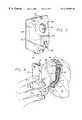
- FIG. 1depicts an optical assembly mounted in a vehicle according to one embodiment of the present invention
- FIG. 2is a side view of the optical assembly according to one embodiment of the present invention.
- FIGS. 3 & 4are front perspective views of two brackets for an optical assembly according to two embodiments of the present invention.
- FIG. 5is a front perspective view of an optical device of the optical assembly according to one embodiment of the present invention.
- FIGS. 6 & 7illustrate the assembly of the two piece optical assembly according to one embodiment of the present invention.
- the present inventionprovides an optical assembly which allows the optics and associated electronics of the system to be removably mounted, for example, to the windshield of a vehicle in front of the dashboard.
- a preferred applicationis for an optical lane departure warning system, but the invention is not so limited.
- An active vehicle steering system employing lane boundary detection from an optical assembly including a camerais another application, an example of which is shown in U.S. Pat. No. 5,485,378 issued Jan. 16, 1996 to Franke, et al., the disclosure of which is incorporated herein by reference. Many other active and passive vehicle safety and driver assistance applications are also possible, however.
- like element numeralsare used to describe like elements illustrated in one or more of the above-described figures.
- FIG. 1a depiction of the overall architecture of an optical assembly for a lane departure warning system according to one embodiment is shown mounted in front of the dash of a vehicle.
- the optical assembly of the present inventionis preferably a two piece assembly and includes mounting bracket 1 and optical device 2 .
- the optical assemblyis not drawn to scale in FIG. 1 and is enlarged relative to the vehicle dash for ease of illustration.
- Optical device 2includes a housing as shown which contains the various optical components that are necessary for the optical monitoring system, e.g., a lane departure warning system in a presently preferred application, and may preferably be a digital camera.
- Optical device 2is shown in the operating position as inserted in bracket 1 .
- bracket 1 and optical device 2can be made of any suitable material, including metal, however a hard plastic is presently preferred.
- Bracket 1is illustrated in FIG. 1 attached to windshield 31 of vehicle 3 in front of dashboard 32 , inside vehicle 3 .
- bracket 1can also be attached to other locations of vehicle 3 , such as on the dashboard or roof, or the exterior such as behind a transparent panel in the vehicle grill, etc.
- vehicle 3is shown in one embodiment as being a truck, the optical mounting assembly of the present invention can be employed for other vehicles, such as automobiles or motorcycles.
- the optical assemblyincluding bracket 1 and optical device 2 , is shown in a side view in FIG. 2 according to one embodiment of the present invention.
- Optical device 2is shown in the operating position inserted in mounting bracket 1 .
- Bracket 1is fixedly attached to windshield 31 , for example, by use of an adhesive 41 .
- adhesive 41is situated to create a tight seal between windshield 31 and the front surface 14 of bracket 1 .
- Flexible cable 4connects to electrical socket 47 via a mated plug so that the two parts can be easily separated to remove optical device 2 for repair, reprogramming, etc.
- Flexible cable 4contains leads which route signals such as vehicle status (e.g., speed, turn signal status, etc.), disable inputs, and warning/stereo mute signals between optical device 2 and the vehicle 3 through dashboard 32 .
- Flexible cable 4also provides power from the vehicle power supply to optical device 2 .
- a need for power leads in flexible cable 4could be completely eliminated by including a battery (not shown) in or on optical device 2 .
- the image processing and warning control circuitry and softwareare preferably configured inside optical device 2 , this electronics could optionally be configured outside of the housing of optical device 2 . Normally, some wiring from optical device 2 will be required however, to avoid providing audible warning amplification circuits and speakers in device 2 .
- FIGS. 3 & 4show two embodiments of the bracket of the present invention. These two embodiments provide different solutions to the problem of fogging of the lens of the optical device. Which approach is preferred will depend on the combination of the vehicle dash and windshield configuration and whether a suitable airflow is adjacent to the assembly.
- bracket 1generally is an opened up U-shaped device comprising a base 15 and two arm members 16 and 17 .
- Base 15has a flat front surface 14 and a back surface 18 .
- front surface 14is fixedly attached to windshield 31 .
- This attachmentcan be accomplished by any suitable means, including glue or adhesive tape.
- Such attachment meansalso preferably serves as a seal which completely surrounds opening 12 and prevents moisture entering.
- a separate sealsuch as an annular gasket may be employed. If formed of a suitable mastic material, such gasket could also affix the bracket to the windshield.
- an annular seal 41is shown located on back surface 18 of bracket 1 and encircles circular opening 12 .
- Annular seal 41can be made of plastic or rubber material and is employed to create a seal between back surface 18 and optical device 2 in order to prevent fogging of the lens element of optical device 2 .
- circular opening 12allows optical device 2 to receive light for imaging the roadway for lane detection, through windshield 31 .
- Elongated opening 13 and groove members 19are located so as to provide an anchoring mechanism for holding optical device 2 in place against bracket 1 , as described below.
- Bracket 11is another embodiment of the bracket for the optical mounting assembly of the present invention.
- Bracket 11generally also is an oblique U-shaped device comprising a base 25 and two arm members 26 and 27 .
- Base 25has a front surface 24 and a back surface 28 .
- front surface 24is fixedly attached to windshield 31 .
- This attachmentcan be accomplished by any suitable means, including glue or adhesive tape.
- Optical device 2is removably attached to bracket 11 against back surface 28 .
- Base 25also has a circular opening 22 . When optical device 2 is seated in position against bracket 1 , circular opening 22 allows optical device 2 to receive an image for lane detection through windshield 31 .
- Elongated opening 23 and groove members 29are located so as to provide an anchoring mechanism for holding optical device 2 in place against bracket 11 .
- openings 30 & 42are located so as to create a channel to allow airflow from the vehicle air blowers to pass through bracket 11 and across the lens element of housing component device 2 to prevent fogging of the lens element.
- opening 35is located on front surface 39 .
- a lens element 45is located within or behind opening 35 .
- Imager 44is shown by dashed lines within optical device 2 for illustration purposes. In operation, for example, in a preferred embodiment of a lane departure warning system, an image of the roadway ahead of the vehicle is formed by the lens element 45 and focused on imager 44 to detect lane markers on the roadway.
- optical device 2includes notches 37 and support extension 36 which are used to secure optical device 2 to bracket 1 , as described below.
- FIG. 6depicts the operation of mounting optical device 2 to bracket 1 (shown in FIG. 3 ).
- bracket 1is shown fixedly attached to windshield 31 .
- Optical device 2is then mounted to bracket 1 at two connection points as follows: 1) support extension 36 is placed inside elongated opening 13 , and 2) notches 37 are locked into groove members 19 .
- front surface 39 of optical device 2is seated against back surface 18 of bracket 1 .
- annular seal 41is shown surrounding opening 12 .
- Annular seal 41can comprise any suitable material such as rubber.
- sealing device 41creates a seal around the lens element located within opening 35 of optical device 2 in order to prevent fogging of the lens element. It will be appreciated that the optical device may thus be easily mounted to, and removed from, bracket 1 to facilitate repair or replacement, adjustment, etc.
- FIG. 7shows the optical assembly of the present invention in the operating position according to another embodiment of the bracket.
- Optical device 2is seated within bracket 11 (as shown in FIG. 4) and removably attached at two connection points as follows: 1) support extension 36 is placed inside elongated opening 23 , and 2) notches 37 are locked into grooves 29 (not shown).
- Front surface 24 of bracket 11can be fixedly attached to windshield 31 of vehicle 3 .
- the lens element 45which is located within opening 35 of optical device 2 , forms an image, e.g., the roadway ahead of the vehicle from light provided through circular opening 22 of bracket 11 and windshield 31 .
- Imager 44receives the roadway images and provides digital image data corresponding to these images to be used, e.g., for lane detection.
- openings 30 & 42 in bracket 11are located so as to create a channel to allow airflow from a vehicle air blower to pass through bracket 11 and across the lens element of optical device 2 to prevent fogging of the lens element.
- both embodiments of the mounting bracketallow the optical device 2 to be securely mounted yet easily removed. Also, the problem of fogging of the lens element of the optical device is avoided. Furthermore, the overall assembly is unobtrusive and may easily fit behind the dash of most vehicles.
- the optical assemblyneed not be mounted to the windshield of a vehicle, but may be mounted elsewhere.
- the bracketmay be integrated into a position of the vehicle as part of the vehicle design.
Landscapes
- Engineering & Computer Science (AREA)
- Mechanical Engineering (AREA)
- Fittings On The Vehicle Exterior For Carrying Loads, And Devices For Holding Or Mounting Articles (AREA)
Abstract
Description
Claims (11)
Priority Applications (4)
| Application Number | Priority Date | Filing Date | Title |
|---|---|---|---|
| US09/038,666US6170955B1 (en) | 1998-02-27 | 1998-02-27 | Vehicle mounted optical assembly |
| PCT/US1999/004364WO1999043242A1 (en) | 1998-02-27 | 1999-02-26 | Vehicle mounted optical assembly |
| JP2000533047AJP2002504453A (en) | 1998-02-27 | 1999-02-26 | Optical assembly mounted on vehicle |
| EP99909674AEP1056374A1 (en) | 1998-02-27 | 1999-02-26 | Vehicle mounted optical assembly |
Applications Claiming Priority (1)
| Application Number | Priority Date | Filing Date | Title |
|---|---|---|---|
| US09/038,666US6170955B1 (en) | 1998-02-27 | 1998-02-27 | Vehicle mounted optical assembly |
Publications (1)
| Publication Number | Publication Date |
|---|---|
| US6170955B1true US6170955B1 (en) | 2001-01-09 |
Family
ID=21901215
Family Applications (1)
| Application Number | Title | Priority Date | Filing Date |
|---|---|---|---|
| US09/038,666Expired - LifetimeUS6170955B1 (en) | 1998-02-27 | 1998-02-27 | Vehicle mounted optical assembly |
Country Status (4)
| Country | Link |
|---|---|
| US (1) | US6170955B1 (en) |
| EP (1) | EP1056374A1 (en) |
| JP (1) | JP2002504453A (en) |
| WO (1) | WO1999043242A1 (en) |
Cited By (44)
| Publication number | Priority date | Publication date | Assignee | Title |
|---|---|---|---|---|
| US20030059218A1 (en)* | 2001-06-13 | 2003-03-27 | Mitsubishi Denki Kabushiki Kaisha | Sensor in car window |
| EP1389566A1 (en)* | 2002-08-16 | 2004-02-18 | Hella KG Hueck & Co. | Camera arrangement for motor vehicles |
| EP1389565A1 (en)* | 2002-08-16 | 2004-02-18 | Hella KG Hueck & Co. | Camera arrangement for motor vehicles |
| US20040164851A1 (en)* | 2003-02-24 | 2004-08-26 | Crawshaw Richard D. | Lane tracking system employing redundant image sensing devices |
| US20040208497A1 (en)* | 2001-12-20 | 2004-10-21 | Ulrich Seger | Stereo camera arrangement in a motor vehicle |
| US20050117052A1 (en)* | 2003-12-02 | 2005-06-02 | Wilife Inc. | Network camera mounting system |
| US20050200467A1 (en)* | 2004-03-15 | 2005-09-15 | Anita Au | Automatic signaling systems for vehicles |
| EP1625976A1 (en)* | 2004-08-14 | 2006-02-15 | Robert Bosch GmbH | Image pickup system |
| US20060054802A1 (en)* | 2004-09-15 | 2006-03-16 | Donal Johnston | Self-adjusting lens mount for automated assembly of vehicle sensors |
| US20060056077A1 (en)* | 2004-09-15 | 2006-03-16 | Donal Johnston | Method for assembling a self-adjusting lens mount for automated assembly of vehicle sensors |
| EP1637401A1 (en)* | 2004-09-15 | 2006-03-22 | Robert Bosch Gmbh | Imaging system |
| EP1707440A2 (en) | 2005-04-01 | 2006-10-04 | Hella KGaA Hueck & Co. | Fixation of electronic components in the vicinity of a vehicle windscreen |
| US20070041725A1 (en)* | 2004-05-19 | 2007-02-22 | Leopold Kostal Gmbh & Co. Kg | Camera arrangement for a motor vehicle |
| US20100208077A1 (en)* | 2000-03-02 | 2010-08-19 | Donnelly Corporation | Accessory system for vehicle |
| US8405726B2 (en) | 2002-01-31 | 2013-03-26 | Donnelly Corporation | Vehicle accessory system |
| US8481916B2 (en) | 1998-01-07 | 2013-07-09 | Magna Electronics Inc. | Accessory mounting system for a vehicle having a light absorbing layer with a light transmitting portion for viewing through from an accessory |
| US8513590B2 (en) | 1998-01-07 | 2013-08-20 | Magna Electronics Inc. | Vehicular accessory system with a cluster of sensors on or near an in-cabin surface of the vehicle windshield |
| US20130219742A1 (en)* | 2012-02-23 | 2013-08-29 | Michael Field | Method And Apparatus For Removing And Preventing Lens Surface Contamination On A Vehicle Lens |
| US8531279B2 (en) | 1999-08-25 | 2013-09-10 | Magna Electronics Inc. | Accessory mounting system for a vehicle |
| US8534887B2 (en) | 1997-08-25 | 2013-09-17 | Magna Electronics Inc. | Interior rearview mirror assembly for a vehicle |
| US8570374B2 (en) | 2008-11-13 | 2013-10-29 | Magna Electronics Inc. | Camera for vehicle |
| US8666643B2 (en) | 2010-02-01 | 2014-03-04 | Miovision Technologies Incorporated | System and method for modeling and optimizing the performance of transportation networks |
| US8686840B2 (en) | 2000-03-31 | 2014-04-01 | Magna Electronics Inc. | Accessory system for a vehicle |
| US8692659B2 (en) | 1998-01-07 | 2014-04-08 | Magna Electronics Inc. | Accessory mounting system for vehicle |
| US20150029336A1 (en)* | 2013-07-23 | 2015-01-29 | Dmitry Kucheryuk | Digital video recorder |
| US8998049B1 (en)* | 2014-02-24 | 2015-04-07 | Ronald A. Orr | Vehicle dash accessory holding device |
| US9090213B2 (en) | 2004-12-15 | 2015-07-28 | Magna Electronics Inc. | Accessory mounting system for a vehicle |
| US9171217B2 (en) | 2002-05-03 | 2015-10-27 | Magna Electronics Inc. | Vision system for vehicle |
| US9191634B2 (en) | 2004-04-15 | 2015-11-17 | Magna Electronics Inc. | Vision system for vehicle |
| US9233645B2 (en) | 1999-11-04 | 2016-01-12 | Magna Electronics Inc. | Accessory mounting system for a vehicle |
| US9436880B2 (en) | 1999-08-12 | 2016-09-06 | Magna Electronics Inc. | Vehicle vision system |
| US9434314B2 (en) | 1998-04-08 | 2016-09-06 | Donnelly Corporation | Electronic accessory system for a vehicle |
| US20160257265A1 (en)* | 2015-03-05 | 2016-09-08 | Toyota Jidosha Kabushiki Kaisha | On-vehicle camera mounting structure |
| US9440535B2 (en) | 2006-08-11 | 2016-09-13 | Magna Electronics Inc. | Vision system for vehicle |
| JP2017071334A (en)* | 2015-10-08 | 2017-04-13 | マツダ株式会社 | Auxiliary equipment for vehicles |
| JP2017071335A (en)* | 2015-10-08 | 2017-04-13 | マツダ株式会社 | Vehicle accessory device |
| US20180055170A1 (en)* | 2016-08-31 | 2018-03-01 | Richard G. Ramirez | Devices and methods for mounting mobile computing devices to objects for hands-free viewing |
| US9961240B2 (en) | 2014-10-22 | 2018-05-01 | Denso Corporation | In-vehicle camera device and in-vehicle system |
| DE10392288B4 (en) | 2002-02-18 | 2019-01-17 | Scania Cv Ab | Method for automatically controlling a position of a vehicle, computer program and computer program product |
| US10471905B2 (en) | 2016-05-17 | 2019-11-12 | Toyota Jidosha Kabushiki Kaisha | In-vehicle camera |
| WO2021069726A1 (en)* | 2019-10-11 | 2021-04-15 | Continental Automotive Gmbh | Device for securing an optical device |
| US11203306B2 (en)* | 2018-01-05 | 2021-12-21 | Xirgo Technologies, Llc | Dashboard attachment device |
| US20220161738A1 (en)* | 2020-11-25 | 2022-05-26 | Rivian Ip Holdings, Llc | Vehicle camera mounting assembly |
| US12069401B1 (en) | 2008-10-30 | 2024-08-20 | Rosco, Inc. | Method and system with multiple camera units installed in protective enclosure |
Families Citing this family (16)
| Publication number | Priority date | Publication date | Assignee | Title |
|---|---|---|---|---|
| US5877897A (en) | 1993-02-26 | 1999-03-02 | Donnelly Corporation | Automatic rearview mirror, vehicle lighting control and vehicle interior monitoring system using a photosensor array |
| US6891563B2 (en) | 1996-05-22 | 2005-05-10 | Donnelly Corporation | Vehicular vision system |
| US7655894B2 (en) | 1996-03-25 | 2010-02-02 | Donnelly Corporation | Vehicular image sensing system |
| JP3565749B2 (en)* | 1999-09-22 | 2004-09-15 | 富士重工業株式会社 | Inspection method of imaging direction of on-vehicle camera and its inspection device |
| US6654720B1 (en)* | 2000-05-09 | 2003-11-25 | International Business Machines Corporation | Method and system for voice control enabling device in a service discovery network |
| JP4045871B2 (en)* | 2002-06-21 | 2008-02-13 | トヨタ自動車株式会社 | Camera cover for on-board camera |
| DE10237607B4 (en)* | 2002-08-16 | 2007-01-25 | Hella Kgaa Hueck & Co. | Camera arrangement for motor vehicles |
| US9914546B2 (en) | 2007-12-21 | 2018-03-13 | Bertil R. L. Werjefelt | Electro-optical emergency vision apparatus |
| US8888042B2 (en) | 2008-05-06 | 2014-11-18 | Bertil R. L. Werjefelt | Emergency vision apparatus |
| CN103503431A (en)* | 2011-05-24 | 2014-01-08 | 本田技研工业株式会社 | Vehicle-mounted camera |
| FR2979888B1 (en)* | 2011-09-12 | 2014-07-04 | Renault Sa | ARRANGEMENT FOR THE MOUNTING OF A COMPONENT ON AN EXTERIOR CARRIER PIECE OF A MOTOR VEHICLE |
| WO2014095455A1 (en)* | 2012-12-20 | 2014-06-26 | Continental Automotive Gmbh | Mounting device for a motor vehicle |
| JP6767186B2 (en)* | 2016-07-20 | 2020-10-14 | 日野自動車株式会社 | In-vehicle camera device |
| WO2019127409A1 (en)* | 2017-12-29 | 2019-07-04 | 深圳市锐明技术股份有限公司 | Driving recorder |
| WO2019127411A1 (en)* | 2017-12-29 | 2019-07-04 | 深圳市锐明技术股份有限公司 | Driving recorder |
| JP2019166964A (en)* | 2018-03-23 | 2019-10-03 | ソニーセミコンダクタソリューションズ株式会社 | Imaging system and vehicle window for use therein |
Citations (12)
| Publication number | Priority date | Publication date | Assignee | Title |
|---|---|---|---|---|
| US3176602A (en) | 1963-07-03 | 1965-04-06 | Loyal R Wilt | Movie camera and auto dash mounting means |
| US3752376A (en) | 1971-07-29 | 1973-08-14 | F Shelton | Automotive vehicle supporting means for cameras |
| US3833196A (en) | 1972-07-10 | 1974-09-03 | Ever Roll Mfg Corp | Camera support |
| US3859899A (en)* | 1974-02-14 | 1975-01-14 | John Edward Mills | Interior ventilation system with side view mirror de-icing |
| US3928894A (en)* | 1974-11-26 | 1975-12-30 | Illinois Tool Works | Adhesive mounting device |
| US4029246A (en) | 1976-04-13 | 1977-06-14 | Woodruff Robert L | Adjustable stable camera support for vehicles |
| US4093364A (en) | 1977-02-04 | 1978-06-06 | Miller Keith G | Dual path photographic camera for use in motor vehicles |
| US4846382A (en) | 1988-01-13 | 1989-07-11 | Nancy E. Foultner | Dash mounting device |
| US5096287A (en) | 1990-03-15 | 1992-03-17 | Aisin Seiki K.K. | Video camera for an automobile |
| US5111289A (en) | 1990-04-27 | 1992-05-05 | Lucas Gary L | Vehicular mounted surveillance and recording system |
| US5137238A (en) | 1991-09-09 | 1992-08-11 | Hutten Friedrich W | Fast access camera mounting device |
| US5246193A (en) | 1992-12-23 | 1993-09-21 | Faidley Warren E | Mobile camera mount |
Family Cites Families (6)
| Publication number | Priority date | Publication date | Assignee | Title |
|---|---|---|---|---|
| US3343772A (en)* | 1965-10-24 | 1967-09-26 | Howell | Attachment device for small appliances |
| US4576320A (en)* | 1984-11-29 | 1986-03-18 | Mead F Jerome | Eyeglass holder for operative association with the rear view mirror on a vehicle |
| US4863130A (en)* | 1989-01-13 | 1989-09-05 | Marks Jr Franklin J | Adjustable device for mounting an electronic imaging camera to a surface by vacuum |
| DE4332836C1 (en) | 1993-09-27 | 1994-09-15 | Daimler Benz Ag | Device for steering a vehicle with controlled tracking |
| US5556493A (en)* | 1995-01-13 | 1996-09-17 | Libbey-Owens-Ford Co. | Mounting an optical moisture sensor on a windshield using a vacuum chamber device |
| US5667176A (en)* | 1995-12-04 | 1997-09-16 | Zamarripa; Michael P. | Radar detector unit mounting device for attachment to rearview mirror |
- 1998
- 1998-02-27USUS09/038,666patent/US6170955B1/ennot_activeExpired - Lifetime
- 1999
- 1999-02-26JPJP2000533047Apatent/JP2002504453A/ennot_activeWithdrawn
- 1999-02-26EPEP99909674Apatent/EP1056374A1/ennot_activeWithdrawn
- 1999-02-26WOPCT/US1999/004364patent/WO1999043242A1/ennot_activeApplication Discontinuation
Patent Citations (12)
| Publication number | Priority date | Publication date | Assignee | Title |
|---|---|---|---|---|
| US3176602A (en) | 1963-07-03 | 1965-04-06 | Loyal R Wilt | Movie camera and auto dash mounting means |
| US3752376A (en) | 1971-07-29 | 1973-08-14 | F Shelton | Automotive vehicle supporting means for cameras |
| US3833196A (en) | 1972-07-10 | 1974-09-03 | Ever Roll Mfg Corp | Camera support |
| US3859899A (en)* | 1974-02-14 | 1975-01-14 | John Edward Mills | Interior ventilation system with side view mirror de-icing |
| US3928894A (en)* | 1974-11-26 | 1975-12-30 | Illinois Tool Works | Adhesive mounting device |
| US4029246A (en) | 1976-04-13 | 1977-06-14 | Woodruff Robert L | Adjustable stable camera support for vehicles |
| US4093364A (en) | 1977-02-04 | 1978-06-06 | Miller Keith G | Dual path photographic camera for use in motor vehicles |
| US4846382A (en) | 1988-01-13 | 1989-07-11 | Nancy E. Foultner | Dash mounting device |
| US5096287A (en) | 1990-03-15 | 1992-03-17 | Aisin Seiki K.K. | Video camera for an automobile |
| US5111289A (en) | 1990-04-27 | 1992-05-05 | Lucas Gary L | Vehicular mounted surveillance and recording system |
| US5137238A (en) | 1991-09-09 | 1992-08-11 | Hutten Friedrich W | Fast access camera mounting device |
| US5246193A (en) | 1992-12-23 | 1993-09-21 | Faidley Warren E | Mobile camera mount |
Cited By (129)
| Publication number | Priority date | Publication date | Assignee | Title |
|---|---|---|---|---|
| US9035233B2 (en) | 1997-08-25 | 2015-05-19 | Magna Electronics Inc. | Accessory mounting system for mounting an electronic device at a windshield of a vehicle |
| US8534887B2 (en) | 1997-08-25 | 2013-09-17 | Magna Electronics Inc. | Interior rearview mirror assembly for a vehicle |
| US9718357B2 (en) | 1997-08-25 | 2017-08-01 | Magna Electronics Inc. | Vehicular accessory system |
| US8926151B2 (en) | 1997-08-25 | 2015-01-06 | Magna Electronics Inc. | Vehicular accessory system |
| US8692659B2 (en) | 1998-01-07 | 2014-04-08 | Magna Electronics Inc. | Accessory mounting system for vehicle |
| US9527445B2 (en) | 1998-01-07 | 2016-12-27 | Magna Electronics Inc. | Accessory mounting system for mounting an accessory at a vehicle such that a camera views through the vehicle windshield |
| US8513590B2 (en) | 1998-01-07 | 2013-08-20 | Magna Electronics Inc. | Vehicular accessory system with a cluster of sensors on or near an in-cabin surface of the vehicle windshield |
| US8481916B2 (en) | 1998-01-07 | 2013-07-09 | Magna Electronics Inc. | Accessory mounting system for a vehicle having a light absorbing layer with a light transmitting portion for viewing through from an accessory |
| US9434314B2 (en) | 1998-04-08 | 2016-09-06 | Donnelly Corporation | Electronic accessory system for a vehicle |
| US9436880B2 (en) | 1999-08-12 | 2016-09-06 | Magna Electronics Inc. | Vehicle vision system |
| US9446715B2 (en) | 1999-08-25 | 2016-09-20 | Magna Electronics Inc. | Vision system for a vehicle |
| US8531279B2 (en) | 1999-08-25 | 2013-09-10 | Magna Electronics Inc. | Accessory mounting system for a vehicle |
| US9283900B2 (en) | 1999-08-25 | 2016-03-15 | Magna Electronics Inc. | Accessory mounting system for a vehicle |
| US9539956B2 (en) | 1999-08-25 | 2017-01-10 | Magna Electronics Inc. | Accessory system for a vehicle |
| US8749367B2 (en) | 1999-11-04 | 2014-06-10 | Magna Electronics Inc. | Driver assistance system for a vehicle |
| US9637053B2 (en) | 1999-11-04 | 2017-05-02 | Magna Electronics Inc. | Accessory mounting system for a vehicle |
| US9233645B2 (en) | 1999-11-04 | 2016-01-12 | Magna Electronics Inc. | Accessory mounting system for a vehicle |
| US9193302B2 (en) | 1999-11-04 | 2015-11-24 | Magna Electronics Inc. | Vision system for a vehicle |
| US9843777B2 (en) | 2000-03-02 | 2017-12-12 | Magna Electronics Inc. | Cabin monitoring system for a vehicle |
| US10059265B2 (en) | 2000-03-02 | 2018-08-28 | Magna Electronics Inc. | Vision system for a vehicle |
| US10427604B2 (en) | 2000-03-02 | 2019-10-01 | Magna Electronics Inc. | Vision system for a vehicle |
| US20100208077A1 (en)* | 2000-03-02 | 2010-08-19 | Donnelly Corporation | Accessory system for vehicle |
| US8531278B2 (en) | 2000-03-02 | 2013-09-10 | Magna Electronics Inc. | Accessory system for vehicle |
| US9783125B2 (en) | 2000-03-31 | 2017-10-10 | Magna Electronics Inc. | Accessory system for a vehicle |
| US8686840B2 (en) | 2000-03-31 | 2014-04-01 | Magna Electronics Inc. | Accessory system for a vehicle |
| US20030059218A1 (en)* | 2001-06-13 | 2003-03-27 | Mitsubishi Denki Kabushiki Kaisha | Sensor in car window |
| US20040208497A1 (en)* | 2001-12-20 | 2004-10-21 | Ulrich Seger | Stereo camera arrangement in a motor vehicle |
| US7111996B2 (en)* | 2001-12-20 | 2006-09-26 | Robert Bosch Gmbh | Stereo camera arrangement in a motor vehicle |
| US8749633B2 (en)* | 2002-01-31 | 2014-06-10 | Magna Electronics Inc. | Vehicle accessory system |
| US8405726B2 (en) | 2002-01-31 | 2013-03-26 | Donnelly Corporation | Vehicle accessory system |
| US8508593B1 (en) | 2002-01-31 | 2013-08-13 | Magna Electronics | Vehicle accessory system |
| US20140340519A1 (en)* | 2002-01-31 | 2014-11-20 | Magna Electronics Inc. | Vehicle accessory system |
| US20180118116A1 (en)* | 2002-01-31 | 2018-05-03 | Magna Electronics Inc. | Vehicle camera system |
| US9862323B2 (en)* | 2002-01-31 | 2018-01-09 | Magna Electronics Inc. | Vehicle accessory system |
| US10543786B2 (en)* | 2002-01-31 | 2020-01-28 | Magna Electronics Inc. | Vehicle camera system |
| US20130314538A1 (en)* | 2002-01-31 | 2013-11-28 | Donnelly Corporation | Vehicle accessory system |
| DE10392288B4 (en) | 2002-02-18 | 2019-01-17 | Scania Cv Ab | Method for automatically controlling a position of a vehicle, computer program and computer program product |
| US10118618B2 (en) | 2002-05-03 | 2018-11-06 | Magna Electronics Inc. | Vehicular control system using cameras and radar sensor |
| US10683008B2 (en) | 2002-05-03 | 2020-06-16 | Magna Electronics Inc. | Vehicular driving assist system using forward-viewing camera |
| US9171217B2 (en) | 2002-05-03 | 2015-10-27 | Magna Electronics Inc. | Vision system for vehicle |
| US10351135B2 (en) | 2002-05-03 | 2019-07-16 | Magna Electronics Inc. | Vehicular control system using cameras and radar sensor |
| US9643605B2 (en) | 2002-05-03 | 2017-05-09 | Magna Electronics Inc. | Vision system for vehicle |
| US11203340B2 (en) | 2002-05-03 | 2021-12-21 | Magna Electronics Inc. | Vehicular vision system using side-viewing camera |
| US9555803B2 (en) | 2002-05-03 | 2017-01-31 | Magna Electronics Inc. | Driver assistance system for vehicle |
| US9834216B2 (en) | 2002-05-03 | 2017-12-05 | Magna Electronics Inc. | Vehicular control system using cameras and radar sensor |
| EP1389565A1 (en)* | 2002-08-16 | 2004-02-18 | Hella KG Hueck & Co. | Camera arrangement for motor vehicles |
| US6799904B2 (en)* | 2002-08-16 | 2004-10-05 | Hella Kg Hueck & Co. | Camera arrangement for motor vehicles |
| EP1389566A1 (en)* | 2002-08-16 | 2004-02-18 | Hella KG Hueck & Co. | Camera arrangement for motor vehicles |
| US20040032668A1 (en)* | 2002-08-16 | 2004-02-19 | Heiko Schaefer | Camera arrangement for motor vehicles |
| EP1623876A3 (en)* | 2002-08-16 | 2006-03-01 | Hella KG Hueck & Co. | Camera arrangement for motor vehicles |
| US6930593B2 (en) | 2003-02-24 | 2005-08-16 | Iteris, Inc. | Lane tracking system employing redundant image sensing devices |
| US20040164851A1 (en)* | 2003-02-24 | 2004-08-26 | Crawshaw Richard D. | Lane tracking system employing redundant image sensing devices |
| US20050117052A1 (en)* | 2003-12-02 | 2005-06-02 | Wilife Inc. | Network camera mounting system |
| US7599002B2 (en)* | 2003-12-02 | 2009-10-06 | Logitech Europe S.A. | Network camera mounting system |
| US8378805B2 (en) | 2004-03-15 | 2013-02-19 | Anita Au | Automatic signaling system for vehicles |
| US20090189756A1 (en)* | 2004-03-15 | 2009-07-30 | Gerald Chan | Automatic signaling system for vehicles |
| US7482916B2 (en) | 2004-03-15 | 2009-01-27 | Anita Au | Automatic signaling systems for vehicles |
| US9248777B2 (en) | 2004-03-15 | 2016-02-02 | Anita Au | Automatic signaling system for vehicles |
| US10569700B2 (en) | 2004-03-15 | 2020-02-25 | Anita Au | Automatic control systems for vehicles |
| US10293743B2 (en) | 2004-03-15 | 2019-05-21 | Anita Au | Automatic control systems for vehicles |
| US7986223B2 (en) | 2004-03-15 | 2011-07-26 | Anita Au | Automatic signaling system for vehicles |
| US9505343B2 (en) | 2004-03-15 | 2016-11-29 | Anita Au | Automatic control systems for vehicles |
| US20050200467A1 (en)* | 2004-03-15 | 2005-09-15 | Anita Au | Automatic signaling systems for vehicles |
| US11897388B2 (en) | 2004-03-15 | 2024-02-13 | Autosignal Llc | Camera systems for vehicles |
| US10046696B2 (en) | 2004-03-15 | 2018-08-14 | Anita Au | Automatic control systems for vehicles |
| US10306190B1 (en) | 2004-04-15 | 2019-05-28 | Magna Electronics Inc. | Vehicular control system |
| US10110860B1 (en) | 2004-04-15 | 2018-10-23 | Magna Electronics Inc. | Vehicular control system |
| US9428192B2 (en) | 2004-04-15 | 2016-08-30 | Magna Electronics Inc. | Vision system for vehicle |
| US10015452B1 (en) | 2004-04-15 | 2018-07-03 | Magna Electronics Inc. | Vehicular control system |
| US10187615B1 (en) | 2004-04-15 | 2019-01-22 | Magna Electronics Inc. | Vehicular control system |
| US9191634B2 (en) | 2004-04-15 | 2015-11-17 | Magna Electronics Inc. | Vision system for vehicle |
| US9609289B2 (en) | 2004-04-15 | 2017-03-28 | Magna Electronics Inc. | Vision system for vehicle |
| US9948904B2 (en) | 2004-04-15 | 2018-04-17 | Magna Electronics Inc. | Vision system for vehicle |
| US10462426B2 (en) | 2004-04-15 | 2019-10-29 | Magna Electronics Inc. | Vehicular control system |
| US10735695B2 (en) | 2004-04-15 | 2020-08-04 | Magna Electronics Inc. | Vehicular control system with traffic lane detection |
| US11503253B2 (en) | 2004-04-15 | 2022-11-15 | Magna Electronics Inc. | Vehicular control system with traffic lane detection |
| US11847836B2 (en) | 2004-04-15 | 2023-12-19 | Magna Electronics Inc. | Vehicular control system with road curvature determination |
| US9736435B2 (en) | 2004-04-15 | 2017-08-15 | Magna Electronics Inc. | Vision system for vehicle |
| US7322755B2 (en) | 2004-05-19 | 2008-01-29 | Leopold Kostal Gmbh & Co. Kg | Camera arrangement for a motor vehicle |
| US20070041725A1 (en)* | 2004-05-19 | 2007-02-22 | Leopold Kostal Gmbh & Co. Kg | Camera arrangement for a motor vehicle |
| EP1625976A1 (en)* | 2004-08-14 | 2006-02-15 | Robert Bosch GmbH | Image pickup system |
| US9266474B2 (en)* | 2004-08-18 | 2016-02-23 | Magna Electronics Inc. | Accessory system for vehicle |
| US8710969B2 (en)* | 2004-08-18 | 2014-04-29 | Magna Electronics Inc. | Accessory system for vehicle |
| US10773724B2 (en)* | 2004-08-18 | 2020-09-15 | Magna Electronics Inc. | Accessory system for vehicle |
| US20160167667A1 (en)* | 2004-08-18 | 2016-06-16 | Magna Electronics Inc. | Accessory system for vehicle |
| US20140253730A1 (en)* | 2004-08-18 | 2014-09-11 | Magna Electronics Inc. | Accessory system for vehicle |
| US20140009672A1 (en)* | 2004-08-18 | 2014-01-09 | Magna Electronics Inc. | Accessory system for vehicle |
| US20060054802A1 (en)* | 2004-09-15 | 2006-03-16 | Donal Johnston | Self-adjusting lens mount for automated assembly of vehicle sensors |
| US20060056077A1 (en)* | 2004-09-15 | 2006-03-16 | Donal Johnston | Method for assembling a self-adjusting lens mount for automated assembly of vehicle sensors |
| EP1637401A1 (en)* | 2004-09-15 | 2006-03-22 | Robert Bosch Gmbh | Imaging system |
| US9090213B2 (en) | 2004-12-15 | 2015-07-28 | Magna Electronics Inc. | Accessory mounting system for a vehicle |
| US10046714B2 (en) | 2004-12-15 | 2018-08-14 | Magna Electronics Inc. | Accessory mounting system for a vehicle |
| US10710514B2 (en) | 2004-12-15 | 2020-07-14 | Magna Electronics Inc. | Accessory mounting system for a vehicle |
| EP1707440A2 (en) | 2005-04-01 | 2006-10-04 | Hella KGaA Hueck & Co. | Fixation of electronic components in the vicinity of a vehicle windscreen |
| DE202006020938U1 (en) | 2005-04-01 | 2011-01-20 | Hella Kgaa Hueck & Co. | Attachment of electronic components in the area of the windshield of a vehicle |
| DE102005014961A1 (en)* | 2005-04-01 | 2006-10-05 | Hella Kgaa Hueck & Co. | Attachment of electronic components in the area of the windshield of a vehicle |
| US11148583B2 (en) | 2006-08-11 | 2021-10-19 | Magna Electronics Inc. | Vehicular forward viewing image capture system |
| US10071676B2 (en) | 2006-08-11 | 2018-09-11 | Magna Electronics Inc. | Vision system for vehicle |
| US9440535B2 (en) | 2006-08-11 | 2016-09-13 | Magna Electronics Inc. | Vision system for vehicle |
| US10787116B2 (en) | 2006-08-11 | 2020-09-29 | Magna Electronics Inc. | Adaptive forward lighting system for vehicle comprising a control that adjusts the headlamp beam in response to processing of image data captured by a camera |
| US11396257B2 (en) | 2006-08-11 | 2022-07-26 | Magna Electronics Inc. | Vehicular forward viewing image capture system |
| US11951900B2 (en) | 2006-08-11 | 2024-04-09 | Magna Electronics Inc. | Vehicular forward viewing image capture system |
| US11623559B2 (en) | 2006-08-11 | 2023-04-11 | Magna Electronics Inc. | Vehicular forward viewing image capture system |
| US12069401B1 (en) | 2008-10-30 | 2024-08-20 | Rosco, Inc. | Method and system with multiple camera units installed in protective enclosure |
| US8570374B2 (en) | 2008-11-13 | 2013-10-29 | Magna Electronics Inc. | Camera for vehicle |
| US8666643B2 (en) | 2010-02-01 | 2014-03-04 | Miovision Technologies Incorporated | System and method for modeling and optimizing the performance of transportation networks |
| US9796359B2 (en)* | 2012-02-23 | 2017-10-24 | The Raymond Corporation | Method and apparatus for removing and preventing lens surface contamination on a vehicle lens |
| US20130219742A1 (en)* | 2012-02-23 | 2013-08-29 | Michael Field | Method And Apparatus For Removing And Preventing Lens Surface Contamination On A Vehicle Lens |
| CN103286097B (en)* | 2012-02-23 | 2017-12-12 | 雷蒙德股份有限公司 | Method and apparatus for removing and preventing the lens surface contamination on vehicle lens |
| CN103286097A (en)* | 2012-02-23 | 2013-09-11 | 雷蒙德股份有限公司 | Method and apparatus for removing and preventing lens surface contamination on a vehicle lens |
| US20150029336A1 (en)* | 2013-07-23 | 2015-01-29 | Dmitry Kucheryuk | Digital video recorder |
| CN104349103A (en)* | 2013-07-23 | 2015-02-11 | 阿科诺里私人有限公司 | Digital video recorder |
| CN104349103B (en)* | 2013-07-23 | 2019-07-30 | 阿科诺里私人有限公司 | Digital video recorder |
| US8998049B1 (en)* | 2014-02-24 | 2015-04-07 | Ronald A. Orr | Vehicle dash accessory holding device |
| US9961240B2 (en) | 2014-10-22 | 2018-05-01 | Denso Corporation | In-vehicle camera device and in-vehicle system |
| US9802550B2 (en)* | 2015-03-05 | 2017-10-31 | Toyota Jidosha Kabushiki Kaisha | On-vehicle camera mounting structure |
| US20160257265A1 (en)* | 2015-03-05 | 2016-09-08 | Toyota Jidosha Kabushiki Kaisha | On-vehicle camera mounting structure |
| JP2017071335A (en)* | 2015-10-08 | 2017-04-13 | マツダ株式会社 | Vehicle accessory device |
| JP2017071334A (en)* | 2015-10-08 | 2017-04-13 | マツダ株式会社 | Auxiliary equipment for vehicles |
| US10471905B2 (en) | 2016-05-17 | 2019-11-12 | Toyota Jidosha Kabushiki Kaisha | In-vehicle camera |
| US20180055170A1 (en)* | 2016-08-31 | 2018-03-01 | Richard G. Ramirez | Devices and methods for mounting mobile computing devices to objects for hands-free viewing |
| US10470542B2 (en)* | 2016-08-31 | 2019-11-12 | Richard G. Ramirez | Devices and methods for mounting mobile computing devices to objects for hands-free viewing |
| US11203306B2 (en)* | 2018-01-05 | 2021-12-21 | Xirgo Technologies, Llc | Dashboard attachment device |
| WO2021069726A1 (en)* | 2019-10-11 | 2021-04-15 | Continental Automotive Gmbh | Device for securing an optical device |
| US12242174B2 (en) | 2019-10-11 | 2025-03-04 | Continental Automotive Gmbh | Device for securing an optical device |
| CN114537292A (en)* | 2020-11-25 | 2022-05-27 | 瑞维安知识产权控股有限责任公司 | Vehicle camera mounting assembly |
| US20220161738A1 (en)* | 2020-11-25 | 2022-05-26 | Rivian Ip Holdings, Llc | Vehicle camera mounting assembly |
| US11827157B2 (en)* | 2020-11-25 | 2023-11-28 | Rivian Ip Holdings, Llc | Vehicle camera mounting assembly |
| CN114537292B (en)* | 2020-11-25 | 2024-05-24 | 瑞维安知识产权控股有限责任公司 | Vehicle Camera Mounting Kit |
Also Published As
| Publication number | Publication date |
|---|---|
| JP2002504453A (en) | 2002-02-12 |
| EP1056374A1 (en) | 2000-12-06 |
| WO1999043242A1 (en) | 1999-09-02 |
Similar Documents
| Publication | Publication Date | Title |
|---|---|---|
| US6170955B1 (en) | Vehicle mounted optical assembly | |
| US11072288B2 (en) | Vehicular exterior rearview mirror assembly with blind spot indicator element | |
| US10773724B2 (en) | Accessory system for vehicle | |
| US6390631B1 (en) | System for automatic adjustment of external mirrors for motor vehicles when driving in curves | |
| US6447128B1 (en) | Rearview mirror assembly for a vehicle with monitor | |
| USRE37709E1 (en) | System for recording and modifying behavior of passenger in passenger vehicles | |
| JP3349412B2 (en) | Vehicle mounted camera | |
| JPH08167100A (en) | Steering device | |
| US10703301B2 (en) | Backup camera enabling device | |
| US10471905B2 (en) | In-vehicle camera | |
| US20100033570A1 (en) | Driver observation and security system and method therefor | |
| JP5005186B2 (en) | In-vehicle camera structure | |
| JPH05294183A (en) | On-vehicle monitoring camera device | |
| JP2004025930A (en) | Camera cover for vehicle mounted camera | |
| US7095569B2 (en) | Lens system for a motor vehicle vision system | |
| JP4718243B2 (en) | Connector unit, in-vehicle digital camera, door mirror with in-vehicle camera | |
| KR102457633B1 (en) | Apparatus for real-time road condition check of vehicle front on the right outdoor side | |
| KR200415133Y1 (en) | Left, right, rear surveillance cameras for cars | |
| JP2004196208A (en) | Automobile surroundings recognizing device | |
| CN114537292B (en) | Vehicle Camera Mounting Kit | |
| CN110861585B (en) | Arrangement structure of imaging unit for vehicle | |
| JP4231962B2 (en) | Vehicle monitoring device | |
| NL2033251B1 (en) | Truck comprising a camera housing that encloses a camera module | |
| KR102738750B1 (en) | A vehicle side mirrors capable of forward checking and interlocking system thereof | |
| KR20200021365A (en) | Assembly for advanced driver asistance system |
Legal Events
| Date | Code | Title | Description |
|---|---|---|---|
| AS | Assignment | Owner name:ODETICS, INC., CALIFORNIA Free format text:ASSIGNMENT OF ASSIGNORS INTEREST;ASSIGNORS:COLEMAN, JEFFREY R.;CAMPBELL, HUGH P.;REEL/FRAME:010711/0220 Effective date:19991230 Owner name:ITERIS, INC., CALIFORNIA Free format text:ASSIGNMENT OF ASSIGNORS INTEREST;ASSIGNOR:ODETICS, INC.;REEL/FRAME:010712/0438 Effective date:19991231 | |
| STCF | Information on status: patent grant | Free format text:PATENTED CASE | |
| AS | Assignment | Owner name:SUNROCK CAPITAL CORP., PENNSYLVANIA Free format text:SECURITY INTEREST;ASSIGNOR:ITERIS, INC. (A DELAWARE CORPORATION);REEL/FRAME:012428/0688 Effective date:20010806 | |
| AS | Assignment | Owner name:TECHNOLOGY LENDING PARTNERS, LLC, CALIFORNIA Free format text:SECURITY AGREEMENT;ASSIGNOR:ODETICS, INC.;REEL/FRAME:013011/0691 Effective date:20020222 | |
| AS | Assignment | Owner name:WELLS FARGO BUSINESS CREDIT, INC., CALIFORNIA Free format text:SECURITY INTEREST ASSIGNMENT;ASSIGNOR:SUNROCK CAPITAL CORP., A DELAWARE CORPORATION;REEL/FRAME:013913/0374 Effective date:20030321 | |
| FPAY | Fee payment | Year of fee payment:4 | |
| AS | Assignment | Owner name:SILICON VALLEY BANK, CALIFORNIA Free format text:SECURITY AGREEMENT;ASSIGNOR:ITERIS, INC.;REEL/FRAME:018433/0751 Effective date:20061009 | |
| AS | Assignment | Owner name:WELLS FARGO BUSINESS CREDIT (AS SUCCESSOR BY MERGE Free format text:RELEASE OF SECURITY INTEREST;ASSIGNOR:ITERIS, INC.;REEL/FRAME:019181/0803 Effective date:20070330 | |
| FEPP | Fee payment procedure | Free format text:PAYOR NUMBER ASSIGNED (ORIGINAL EVENT CODE: ASPN); ENTITY STATUS OF PATENT OWNER: LARGE ENTITY Free format text:PAT HOLDER CLAIMS SMALL ENTITY STATUS, ENTITY STATUS SET TO SMALL (ORIGINAL EVENT CODE: LTOS); ENTITY STATUS OF PATENT OWNER: LARGE ENTITY | |
| FPAY | Fee payment | Year of fee payment:8 | |
| FEPP | Fee payment procedure | Free format text:PAYER NUMBER DE-ASSIGNED (ORIGINAL EVENT CODE: RMPN); ENTITY STATUS OF PATENT OWNER: LARGE ENTITY Free format text:PAYOR NUMBER ASSIGNED (ORIGINAL EVENT CODE: ASPN); ENTITY STATUS OF PATENT OWNER: LARGE ENTITY | |
| AS | Assignment | Owner name:ITERIS, INC., CALIFORNIA Free format text:CORRECTIVE ASSIGNMENT TO CORRECT THE ERROR IN THE PATENT NUMBER 6170955 ORIGINALLY RECORDED UNDER REEL 018433, FRAME 0751. ON THE ORIGINAL RELEASE THAT WAS FILED, REEL 025641 FRAME 0641 THE PATENT WAS LISTED INCORRECTLY AS 6710955, WE NEED IT TO BE CORRECTED AND THE ENTIRE REEL AND FRAME (018433/0751) REASSIGNED BACK TO ITERIS INC;ASSIGNOR:SILICON VALLEY BANK;REEL/FRAME:026677/0875 Effective date:20110728 | |
| AS | Assignment | Owner name:BENDIX COMMERCIAL VEHICLE SYSTEMS LLC, OHIO Free format text:ASSIGNMENT OF ASSIGNORS INTEREST;ASSIGNOR:ITERIS, INC.;REEL/FRAME:026689/0937 Effective date:20110729 | |
| FEPP | Fee payment procedure | Free format text:PAT HOLDER NO LONGER CLAIMS SMALL ENTITY STATUS, ENTITY STATUS SET TO UNDISCOUNTED (ORIGINAL EVENT CODE: STOL); ENTITY STATUS OF PATENT OWNER: LARGE ENTITY | |
| FPAY | Fee payment | Year of fee payment:12 |