US6170162B1 - Rotary displacement system using differential measuring - Google Patents
Rotary displacement system using differential measuringDownload PDFInfo
- Publication number
- US6170162B1 US6170162B1US09/320,593US32059399AUS6170162B1US 6170162 B1US6170162 B1US 6170162B1US 32059399 AUS32059399 AUS 32059399AUS 6170162 B1US6170162 B1US 6170162B1
- Authority
- US
- United States
- Prior art keywords
- detector
- emitter
- tracks
- disk
- absolute
- Prior art date
- Legal status (The legal status is an assumption and is not a legal conclusion. Google has not performed a legal analysis and makes no representation as to the accuracy of the status listed.)
- Expired - Lifetime
Links
- 238000006073displacement reactionMethods0.000titleclaimsabstractdescription57
- 230000005684electric fieldEffects0.000claimsabstractdescription54
- 238000000034methodMethods0.000claimsdescription27
- 230000007704transitionEffects0.000claimsdescription15
- 230000000295complement effectEffects0.000claimsdescription14
- 230000001172regenerating effectEffects0.000claimsdescription9
- 239000000463materialSubstances0.000claimsdescription8
- 238000005259measurementMethods0.000claimsdescription7
- 230000008878couplingEffects0.000claimsdescription6
- 238000010168coupling processMethods0.000claimsdescription6
- 238000005859coupling reactionMethods0.000claimsdescription6
- 238000005314correlation functionMethods0.000claimsdescription5
- 238000004519manufacturing processMethods0.000claimsdescription4
- 229910052581Si3N4Inorganic materials0.000claimsdescription3
- 238000013139quantizationMethods0.000claimsdescription3
- 230000004044responseEffects0.000claimsdescription3
- HQVNEWCFYHHQES-UHFFFAOYSA-Nsilicon nitrideChemical compoundN12[Si]34N5[Si]62N3[Si]51N64HQVNEWCFYHHQES-UHFFFAOYSA-N0.000claimsdescription3
- 230000001360synchronised effectEffects0.000claimsdescription3
- XUIMIQQOPSSXEZ-UHFFFAOYSA-NSiliconChemical compound[Si]XUIMIQQOPSSXEZ-UHFFFAOYSA-N0.000claimsdescription2
- 230000007423decreaseEffects0.000claimsdescription2
- TWNQGVIAIRXVLR-UHFFFAOYSA-Noxo(oxoalumanyloxy)alumaneChemical compoundO=[Al]O[Al]=OTWNQGVIAIRXVLR-UHFFFAOYSA-N0.000claimsdescription2
- 229910052710siliconInorganic materials0.000claimsdescription2
- 239000010703siliconSubstances0.000claimsdescription2
- 238000001514detection methodMethods0.000abstractdescription6
- 238000003491arrayMethods0.000description20
- 230000008901benefitEffects0.000description6
- 238000010586diagramMethods0.000description5
- 230000008859changeEffects0.000description4
- 230000007246mechanismEffects0.000description4
- 229910052751metalInorganic materials0.000description4
- 239000002184metalSubstances0.000description4
- 238000010276constructionMethods0.000description2
- 230000006870functionEffects0.000description2
- 230000006872improvementEffects0.000description2
- 230000010354integrationEffects0.000description2
- 238000001465metallisationMethods0.000description2
- 238000012986modificationMethods0.000description2
- 230000004048modificationEffects0.000description2
- 238000012544monitoring processMethods0.000description2
- 229910052755nonmetalInorganic materials0.000description2
- 239000003921oilSubstances0.000description2
- 230000003287optical effectEffects0.000description2
- 230000008569processEffects0.000description2
- VYZAMTAEIAYCRO-UHFFFAOYSA-NChromiumChemical compound[Cr]VYZAMTAEIAYCRO-UHFFFAOYSA-N0.000description1
- 229910052782aluminiumInorganic materials0.000description1
- XAGFODPZIPBFFR-UHFFFAOYSA-NaluminiumChemical compound[Al]XAGFODPZIPBFFR-UHFFFAOYSA-N0.000description1
- 230000003321amplificationEffects0.000description1
- 238000006243chemical reactionMethods0.000description1
- 229910052804chromiumInorganic materials0.000description1
- 239000011651chromiumSubstances0.000description1
- 239000012141concentrateSubstances0.000description1
- 239000000356contaminantSubstances0.000description1
- 238000011109contaminationMethods0.000description1
- 238000013461designMethods0.000description1
- 229910003460diamondInorganic materials0.000description1
- 239000010432diamondSubstances0.000description1
- 230000000694effectsEffects0.000description1
- 230000005284excitationEffects0.000description1
- 238000002347injectionMethods0.000description1
- 239000007924injectionSubstances0.000description1
- 238000013507mappingMethods0.000description1
- 238000003199nucleic acid amplification methodMethods0.000description1
- 238000002161passivationMethods0.000description1
- 230000010363phase shiftEffects0.000description1
- 238000012545processingMethods0.000description1
- 230000009467reductionEffects0.000description1
- 238000005070samplingMethods0.000description1
- 229910052594sapphireInorganic materials0.000description1
- 239000010980sapphireSubstances0.000description1
- 238000000992sputter etchingMethods0.000description1
- 230000000007visual effectEffects0.000description1
Images


Classifications
- G—PHYSICS
- G01—MEASURING; TESTING
- G01D—MEASURING NOT SPECIALLY ADAPTED FOR A SPECIFIC VARIABLE; ARRANGEMENTS FOR MEASURING TWO OR MORE VARIABLES NOT COVERED IN A SINGLE OTHER SUBCLASS; TARIFF METERING APPARATUS; MEASURING OR TESTING NOT OTHERWISE PROVIDED FOR
- G01D5/00—Mechanical means for transferring the output of a sensing member; Means for converting the output of a sensing member to another variable where the form or nature of the sensing member does not constrain the means for converting; Transducers not specially adapted for a specific variable
- G01D5/12—Mechanical means for transferring the output of a sensing member; Means for converting the output of a sensing member to another variable where the form or nature of the sensing member does not constrain the means for converting; Transducers not specially adapted for a specific variable using electric or magnetic means
- G01D5/14—Mechanical means for transferring the output of a sensing member; Means for converting the output of a sensing member to another variable where the form or nature of the sensing member does not constrain the means for converting; Transducers not specially adapted for a specific variable using electric or magnetic means influencing the magnitude of a current or voltage
- G01D5/24—Mechanical means for transferring the output of a sensing member; Means for converting the output of a sensing member to another variable where the form or nature of the sensing member does not constrain the means for converting; Transducers not specially adapted for a specific variable using electric or magnetic means influencing the magnitude of a current or voltage by varying capacitance
- G01D5/241—Mechanical means for transferring the output of a sensing member; Means for converting the output of a sensing member to another variable where the form or nature of the sensing member does not constrain the means for converting; Transducers not specially adapted for a specific variable using electric or magnetic means influencing the magnitude of a current or voltage by varying capacitance by relative movement of capacitor electrodes
- G01D5/2412—Mechanical means for transferring the output of a sensing member; Means for converting the output of a sensing member to another variable where the form or nature of the sensing member does not constrain the means for converting; Transducers not specially adapted for a specific variable using electric or magnetic means influencing the magnitude of a current or voltage by varying capacitance by relative movement of capacitor electrodes by varying overlap
- G01D5/2415—Mechanical means for transferring the output of a sensing member; Means for converting the output of a sensing member to another variable where the form or nature of the sensing member does not constrain the means for converting; Transducers not specially adapted for a specific variable using electric or magnetic means influencing the magnitude of a current or voltage by varying capacitance by relative movement of capacitor electrodes by varying overlap adapted for encoders
Definitions
- This inventionrelates to a new, improved and precise rotary displacement measuring system in which both absolute and relative measurements of rotary position may be made, with compensation for run out (mechanical wobble or misalignment).
- a number of electrical and electronic deviceshave been proposed for measuring angular position and displacement including so-called rotary variable differential transformers, such as described in U.S. Pat. No. 4,910,488. These devices provide for measuring angular displacement by converting mechanical rotation into an analog electrical signal, which may then be connected to a digital output by a conventional A/D converter.
- a so-called rotary transmitteris disclosed in which rotation of a rotor relative to a pair of stators is determined by variation in capacitance between the rotor and at least one of the stators as the rotor turns.
- prior art rotary measuring devicesuse several detectors to detect capacitance between the detectors and an emitter but then the outputs from the detectors are integrated to produce a single output signal which is typically analog. As noted above, this analog signal may then be converted to a digital signal for use and interpretation by the user. Finally, prior art devices have typically utilized multiple inputs to excite an emitter and in particular certain sections or segments on the emitter causing it to emit different strength electric fields (usually different phases of an AC excitation signal). Detection of the rotary position of the emitter (or detector) relative to the detector (or emitter) is then made by detecting the variation in strength or phase of the emitted fields.
- rotary displacement and position measuring transducersinclude resistance-based voltage dividers and optical encoders, both of which also suffer from one or more of the disadvantages mentioned above.
- optical encodershave made improvements in the precision of measurements, the devices are still relatively bulky because increased precision is obtained through increasing the number of sensors or other methods which require increased detector surface area.
- a further drawbackis that the rotary displacement and position measuring transducers above typically use a single type of encoder, either absolute or incremental.
- the precision of absolute encodershas been poor relative to incremental encoders, but incremental encoders require indexing to find a reference point for movement.
- VLSIvery large scale integration
- An additional objectis to simultaneously produce absolute and high resolution incremental outputs.
- a rotary displacement measuring systemwhich includes a shaft whose rotary displacement is to be measured, mounted to rotate about its long axis, and an emitter disk coupled to the shaft to rotate as the shaft is rotated.
- the emitter diskdevelops electric fields at predetermined locations on the emitter disk, such locations varying circumferentially on the emitter disk.
- an array of detectorsdisposed in close proximity to the emitter disk, adjacent the path traversed when the emitter disk is rotated, to detect variation in locations of the electric fields as the emitter disk is rotated and to produce output signals representing variations in the electric field locations.
- a plurality of detectorsdetect variations in locations of electric fields on a plurality of tracks. Such variation provides an indication of the position and displacement of the emitter disk and thus of the shaft.
- the emitter diskcomprises a generally planar disk mounted on the shaft to rotate in the plane defined by the emitter disk and to direct electric fields normally from an active side of the emitter disk from different locations thereon.
- the detectorcomprises a generally planar plate disposed in a fixed position to be generally parallel with the emitter disk on the active side thereof to enable detection of variations in the location of electric fields as the emitter disk is rotated.
- the emitter diskis mechanically biased by a spring toward the detector plate, but out of contact therewith.
- a plurality of concentric tracksare formed on the active side of the emitter disk, each track including a plurality of spaced-apart, but electrically connected, conductive sections.
- a conductive layer of materialis disposed on the detector plate on the side facing the active side of the emitter disk for developing an electric field to capacitively couple the layer and the track sections when a voltage signal is supplied to the layer.
- the conductive sectionsare thus caused to develop time varying electric fields to be detected by the detectors.
- a voltage supply sourcesupplies a voltage signal to the conductive layer of material on the detector plate.
- FIG. 1is a side, cross-sectional view of a rotary displacement measuring system made in accordance with the principles of the present invention
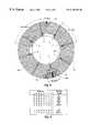
- FIG. 2is a top, plan view of the emitter disk of FIG. 1, showing complimentary segmented emitter disk tracks made in accordance with the principles of the present invention
- FIG. 3is a top, plan view of the detector of FIG. 1 showing individual detector arrays in accordance with the principles of the present invention
- FIG. 4is a table representing exemplary states of the coarse absolute position detectors of FIG. 3 for different emitter disk rotation angles
- FIG. 5is a table showing exemplary states for the coarse absolute position detectors and fine absolute position detectors of FIG. 3 for different emitter disk rotation angles;
- FIG. 6is a block diagram schematic view of a detector element made in accordance with the principles of the present invention.
- FIG. 7is a detailed schematic view of the detector element of FIG. 6;
- FIG. 8is a table showing inputs to the circuit of FIGS. 6 and 7 which are required for detection of rotary displacement
- FIG. 9is a schematic view of decoding circuitry which may be used for synchronizing coarse and fine emitter disk tracks and absolute detectors in accordance with the principles of the present invention.
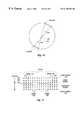
- FIG. 10is a diagram showing how run out causes different amounts of data to be detected by the incremental detector arrays
- FIG. 11is a table showing the “wide” and “narrow” data humps detected in FIG. 10;
- FIG. 12is a table showing experimentally produced run out induced errors for different emitter disk rotation angles
- FIG. 13is a graph demonstrating the principle used by the present invention to compensate for run out
- FIG. 14is a table of “normal” hump templates.
- FIG. 15is a graph of the correlation function.
- the present inventionis able to determine rotary displacement without comparison or conversion of measured signals. It is not the strength or intensity of measured signals which provide rotary displacement information, but rather the differential measurement between complimentary tracks which creates a plurality of reliable binary one-bit signals despite varying gaps between the emitter disk and sensor disk.
- FIG. 1there is shown a side, cross-sectional, fragmented view of one specific illustrative embodiment of a rotary displacement and position measurement transducer made in accordance with the present invention, for measuring the angular displacement or angular position of a shaft 4 which would be coupled at an end 4 a to the object or component whose angular displacement is to be measured.
- the other components of the transducerare mounted about the shaft as will be described.
- a support plate 8Attached to the other end 4 b of the shaft 4 , to rotate therewith, is a support plate 8 .
- an emitter disk 12Spaced from the support plate 8 and slidable mounted on the shaft 4 to rotate therewith is an emitter disk 12 on which will be developed electric fields at various locations which will be directed towards a fixed detector integrated circuit chip 16 .
- a plurality of torsionally stiff, but longitudinally elastic springs 20are coupled between the support plate 8 and the emitter disk 12 to (1) cause the disk 12 to rotate when the shaft 4 and plate 8 are rotated, and (2) lightly urge (bias) the emitter disk 12 against the detector chip 16 .
- the emitter disk 12includes a slightly raised or thickened annular central section or bearing surface 24 to contact and slide over the detector chip 16 but maintain the remaining portions of the emitter disk out of contact (but in close proximity) with the chip.
- the gap 11should be on the order of a few microns.
- a wear resistant film 28commonly referred to as a passivation layer is disposed over the raised portion 24 of the emitter disk 12 and/or the central portion of the detector integrated circuit chip 16 which is in contact with the emitter disk, to prevent wear between the disk and the chip.
- the emitter disk 12could be made of sapphire formed by ion milling of an aluminum oxide.
- the detector chip 16could be a silicon wafer.
- the wear resistant film 28could be made of silicon nitride, a material generally having the hardness of diamond.
- Another embodiment of the emitter disk and detector plateis simply to provide substantially flat facing surfaces for the emitter disk and plate so that there is light contact between the entire facing surfaces.
- the entire surface of the detector and/or emitter diskwould advantageously be coated with a wear-resistant layer of material, such as the aforementioned silicon nitride.
- the emitter diskis maintained in close proximity to the detector plate and the spacing therebetween is maintained substantially uniform as the emitter disk is caused to rotate.
- the detector integrated circuit chip 16is mounted to a base 32 which is slidable mounted about the shaft 40 but is fixed and does not rotate as the shaft is rotated. Obviously, since the base 32 is fixed and does not rotate and the detector chip 16 is mounted on the base, the detector chip likewise does not rotate.
- a bearing 36is disposed between the base 32 and the shaft 40 to allow ease of rotation of the shaft in the base, and a seal 40 is likewise disposed between the base 32 and shaft 40 to prevent entry of contaminants into the area occupied by the emitter disk 12 and detector chip 16 .
- a cover or cap 44is placed over the end 4 b of the shaft 4 to cover the plate 8 , emitter disk 12 and chip 16 .
- a cable assembly 48extends through the cap 48 to electrically contact the detector chip 16 to provide for exchange of electrical signals therebetween, in a manner described in U.S. Pat. No. 5,311,666 issued to Jacobsen on May 17, 1994, which is incorporated herein by reference.
- Other component parts for maintaining the transducer in the desired configurationmay also be included as fully described in the afore-cited parent application.
- the dielectric oilwhich fills the volume 33 defined by the base 32 and the cover 44 .
- the dielectric oilhas a high dielectric constant to concentrate electric fields for increasing coupling.
- the emitter disk 12is also caused to rotate so the electric fields developed by the emitter disk are caused to sweep over the detector chip 16 ; the detector chip detects the instantaneous position of the electric field and provides an output signal indicating the rotary position of the emitter disk and thus of the shaft 4 .
- all electrical connections to the transducermay be made via the cable 48 .
- the shaft 4 whose rotary displacement is to be measuredis allowed to rotate freely and, because it fits through central openings in all of the component parts, it also serves to maintain the parts in proper alignment.
- the component partsare protected from contamination and damage by cover 44 and by the seal 40 .
- the emitter disk 12 and detector integrated circuit chip 16 electronicsallow for significant miniaturization and this, in turn, yields high precision in making the rotary displacement measurements.
- the conductive sectionsare formed to produce a code such that rotation of the emitter disk past specifically placed electric field sensors results in unary (single-bit at a time) changes in the value of the code as the shaft is continuously rotated. The value changes predictably as the emitter disk is rotated. This value is detected to provide the indication of the absolute and incremental rotational displacement (position) of the emitter disk.
- the emitter disk 12does not selectively produce electric field emissions from only a particular set of track elements. Instead, all of the metallized tracks are emitting an electrical field because the tracks form one electrically continuous circuit path. This substantially decreases the complexity of the design of the emitter disk.
- the tracksare formed as complementary or conjugate pairs 54 , 58 and 62 .
- the complementary or conjugate aspect of each pair of tracksis illustrated by reference to segments 58 a and 58 b of the pair of tracks 58 .
- Segment 58 aappears dark in FIG. 2 indicating that it is metallized or is formed of a conductive layer of material whereas the light segment 58 b indicates that the emitter disk is clear at that location, thus containing no metallization.
- Segments 58 a and 58 boccupy the same circumferential position on the emitter disk but, of course, different radial positions.
- Track pair 54provides for “coarse” detection of the absolute position of the emitter disk 12 relative to the detector plate 16 shown in FIG. 3 .
- Eight coarse detectors 56 labeled 0 through 7are circumferentially spaced apart on the detector plate (FIG. 3) and are also shown in FIG. 2 to indicate the positions such detectors occupy relative to the track pair 54 .
- the coarse detectors 56straddle the track pair. Since there are eight coarse detectors and because of the metallization pattern of the track pair 54 —a 67.5 degree arc 65 which is oppositely metallized from the rest of the track pair—the coarse detectors 56 can provide an indication of absolute position of the emitter disk 12 to resolution of 22.5 degrees.
- detectors 4 and 5would be in the “1” state since both detectors are overlying metal on the outside track of the track pair 54 and no metal on the inside track, whereas all other coarse detectors are just the opposite and would be in the “0” state. Note in FIG. 4 that with every 22.5 degree rotation of the emitter disk, only one of the eight coarse detectors 56 changes its output or state. Accordingly, the coarse detectors have 16 unique states.
- the detectors 0 through 7are called absolute detectors because unlike an incremental detector, absolute detectors “know” where they are at the moment that power is supplied. In other words, a sampling of the detector readouts provides an absolute reading of rotational position which is accurate, in this instance, to within 22.5 degrees. This is in contrast to an incremental detector which must pass by some indexing reference mark before the system is able to determine its rotational position as will be discussed later.
- a changewill occur in the state or readout of the fine detector array 70 , i.e., what the fine detector array “sees” of the track pair 58 , every 1.4062 degrees of rotation of the emitter disk 12 .
- FIG. 5shows exemplary readouts of the “fine” detector array and “coarse” detectors for every 1.4 degree rotation of the emitter disk 12 .
- the fine detector arraychanges states 16 times for every one change of the coarse detectors.
- the coarse detectors 56provide for absolute positioning of the emitter disk 12 within 22.5 degrees of rotation and then the fine detector array 70 provides for absolute positioning of the emitter disk 12 within the identified 22.5 degree arc to a resolution of 1.4 degrees.
- FIG. 3is a top plan view of the detector plate 16 of FIG. 1 .
- the detector plate 16includes an annular conductive sheet 80 (coupling sheet) which, when the detector plate 16 is mounted in the transducer assembly of FIG. 1, will face the conductive sections on the emitter disk 16 .
- the annular conductive sheet 80is electrified by a square wave voltage signal from a signal source (not shown) by methods well known to those skilled in the art. Electrifying the conductive sheet 80 causes it to produce an electric field which results in the capacitive coupling of the annular conductive sheet 80 to the metallized portions of the emitter disk 12 to thus cause the conductive sections of the tracks 54 , 58 and 62 to develop electric fields which are, in turn, directed back towards the detector plate 16 .
- the detector plate 16Also disposed on the detector plate 16 are the plurality of absolute coarse detectors 56 , the absolute fine detector array 70 , and diametrically opposite high resolution incremental detector arrays 74 and 78 . As already described, as the emitter disk 12 is rotated, the detectors detect variations in the location of electric fields produced by the track sections, not variations in field strength or phase. As should be obvious from the layout of the detectors 56 , 70 , 74 and 78 , they are arranged so as to be able to detect electric fields from the corresponding coarse, fine and high resolution track pairs on the emitter disk 12 .
- Each detector element or sensor in the detector arraysincludes two electric field sensing elements 90 and 94 as shown in block diagram FIG. 6, each being disposed over a respective track of a complementary pair for intercepting electric fields emanating from the tracks.
- Each sensor in the arraysalso includes a regenerative differential amplifier 98 , coupled to the sensing elements 90 and 94 . With this configuration, the sensing elements 90 and 94 will sense opposite conditions since the two tracks over which they are positioned are conjugate. That is, when one sensing element senses an electric field from an electrified section, the other sensing element will be sensing only a small stray absence of electric field from the fringes of a nearly electrified section.
- signals of different magnitudewill be supplied by the sensing elements 90 and 94 to the differential amplifier 98 .
- the differential amplifier 98produces an output signal representing the difference between values of the input signals.
- FIG. 7provides a detailed schematic diagram of the sensor circuit shown in FIG. 6 .
- bothare simultaneously connected to a bias voltage.
- the biasis evenly balanced for each of the sensor elements 90 and 94 .
- the sensor elements 90 and 94are then isolated from each other, and from the bias source.
- the square-wave signal from the emitter plateis capacitively coupled to the sensing plates.
- the sensor elements 90 and 94each respectively amplify the voltage on their respective sensor element.
- the amplified output of sensor elements 90 and 94is then latched, resulting in the state of the latch being determined by the difference of the amplified outputs. Each latch quantizizes this difference to a binary 0 or 1 state.
- a plurality of differential sensorsproduce digital signals which define the absolute or incremental rotary position of the connected shaft, as previously discussed.
- FIG. 8there are shown in FIG. 8 the four phases of operation of sensor elements 98 .
- the four phasesare shown in the order in which they occur, and are the balance phase 110 , the charge injection phase 111 , the amplification phase 112 and the latching phase 113 .
- Four phasesrequires two inputs to the differential amplifier of FIG. 7 . They are the ISO 115 or isolate input and the BIAS 116 input.
- the table of FIG. 8is rather self-explanatory in that the combinations of signal or no signal on the two inputs activates the appropriate transistors within the sensor elements 90 and 94 to produce the desired result as will be understood by those skilled in the art.
- a significant feature which is different from the prior art and which provides a distinct advantage to the present inventionis the placement of the sensor element circuitry 98 shown in FIG. 7 .
- the circuitryis placed on the opposite side of the detector plate 16 from the emitter disk 12 .
- the sensor circuitryis thus advantageously shielded from stray capacitive coupling to the electric fields generated between the emitter disk 12 and detector plate 16 .
- the intrinsic circuitry comprising the sensor element circuitry 98be symmetric in construction such that the operation of the differential amplifier 98 is within close tolerances. This avoids bias in balanced sensor elements 90 and 94 which can give false position indication signals.
- the sensorsincluding the sensing elements 90 and 94 and differential amplifiers 98 , are fabricated on the detector plate 16 utilizing very large scale integration (VLSI) manufacturing techniques.
- the output of the sensorsare supplied to interpretation logic which may also be fabricated on the detector plate (identified, for example, as circuit logic 102 in FIG. 3) using VLSI techniques.
- Such interpretation or processing logicis shown in FIG. 9 to include a coarse track encoder 120 , a fine track encoder 121 , synchronization logic 122 and a rounding circuit (adder) 123 .
- the circuit diagram of FIG. 9implements a system to compensate for run out. This is accomplished by having redundant information in the circuitry of FIG. 9 available for synchronization.
- the circuit of FIG. 9shows eight bits of coarse detector information 124 and sixteen bits of fine detector information 125 . These bits are sent to encoder circuitry 120 and 121 respectively. As discussed previously in reference to FIG. 4, resolution of the rotary position can be determined to be in one of sixteen different sectors using the eight coarse detectors 56 . In the coarse track encoder circuitry 120 , these sixteen sectors can be represented by a four bit binary number 126 . Likewise, the fine detector array 70 with its sixteen detectors can determine that the emitter disk 12 is in any one of thirty two different positions within the sixteen different sectors. Thirty two positions are represented by a five bit binary number 127 . The result is that the rotary position of the emitter disk 12 is determinable to (16 ⁇ 32) 512 positions.
- FIG. 9also shows that the resolution of the coarse and fine encoders 120 and 121 is only utilized to a resolution of 256 positions. This is because 256 positions are representable by 8 bits of the output 128 . Yet 9 bits of resolution are available (4 coarse bits 126 and 5 fine bits 127 ). Advantageously, 1 position bit is dropped and instead used for synchronization of the coarse and fine detectors 56 and 70 . By sacrificing some resolution, the present invention is assured of synchronous output. Synchronization is accomplished, as will be appreciated by those skilled in the art, by a combination of the synchronization circuitry and the adder or rounding circuitry 123 .
- the 8 bit signal 128 presented to the MUX logicis the rotary displacement of the emitter disk 12 at a resolution of about 1.4 degrees.
- the circuitry of FIG. 9compensates for run out for the coarse and fine sensor element arrays 56 and 70 by discarding one bit of potential resolution.
- a third arrayis available on the same VLSI detector plate 16 of the present invention which combines the advantageous ability of the absolute rotary displacement determining sensor arrays 56 and 70 to know their position upon the application of power to the circuits, with the even greater precision which is achieved using a pair of diametrically opposite incremental or high resolution sensor arrays 74 and 78 (FIG. 3 ).
- the incremental sensor arrays 74 and 78are used to further refine the rotary position of the emitter disk 12 within the 1.4 degree arc determined by the coarse and fine detector arrays 56 and 70 . While it might appear that the greater resolution of the incremental detector arrays 74 and 78 can obtain all of the benefits of the present invention without absolute detectors 56 and 70 , an incremental detector array must first be synchronized to some predetermined reference point. In other words, the detector plate 16 must rotate through some unknown arc length until the incremental detector array finds the reference point. The incremental detector array then uses some counting mechanism which is incremented or decremented with respect to the reference point as the detector plate 16 is passed over by the emitter disk 12 .
- the present inventionadvantageously combines the incremental detector arrays 74 and 78 with the absolute detector arrays 56 and 70 on a single VLSI detector chip 16 .
- the incremental detector array systemis comprised of two diametrically opposite detector arrays 74 and 78 of sixteen sensor elements 98 each.
- the aspect of using diametrically opposite detectorsis well known in the prior art.
- the present inventionis able to tolerate a higher degree of run out than conventional analog rotary detector systems.
- the reason for the significant increase in run out toleranceis the advantageous method of determining a rotary position used by the present invention. Specifically, the method takes advantage of the redundant position information provided by the diametrically opposite detectors arrays 74 and 78 as will be explained.
- FIG. 10illustrates how run out causes the diametrically opposite incremental detector arrays 74 and 78 to report different rotary displacements for the emitter disk 12 .
- the emitter disk 12is shown with an exaggerated amount of run out. Instead of rotating about the center 130 of the emitter disk 12 , the disk rotates about point 131 . Run out causes the angle subtended by arc 132 to be smaller than the angle subtended by arc 133 .
- FIG. 11shows that it is the edges 135 of the reported rotary position which run out can cause to be in error.
- FIG. 11also illustrates the rotary position reported by the left incremental detector array 78 over the larger subtended arc 133 as being a wide hump.
- the rotary position reported by the right incremental detector 137 over the smaller subtended arc 132is seen as a narrow hump because of run out. Without run out, the humps 149 would be the same width, and transitions to 0 or 1 on the left and right edges 135 would occur simultaneously. However, as shown in FIG.
- the left edge 141 of line 139transitions to a 1, while the right edge 142 of line 139 does not transition to a 0 until the rotation of the emitter disk has advanced as shown on line 140 .
- the important feature to noteis that the edges 135 of the humps can change early or late because of the angular shift induced by run out.
- FIG. 12is a table of experimental values showing run out caused errors.
- the columns POS(R) 145 and POS(L) 146representing the positions in decimal detected by the right and left arrays respectively, should transition equally.
- column 146 POS(L)is clearly transitioning early with respect to angular position, while POS(R) 145 is transitioning late with respect to angular position.
- the present inventioncompensates for run out as shown in FIG. 13 .
- Run outis represented as a sinusoidal error induced phase shift 150 and 151 .
- the present inventionsums the position from both arrays 74 and 78 , and then divides by two. The position should then be represented by the straight line 152 , where the net error goes to zero.
- the listing of experimentally obtained valuesshows the positions 145 and 146 determined by an arbitrarily named left detector array 78 , the diametrically opposed right detector array 74 , and the equivalent and respective positions POS(R) 145 and POS(L) 146 . Without run out, the positions in columns 145 and 146 would always be equal.
- Circle 147indicates an early transition of an edge for the left detector array 78
- circle 148indicates an early transition of an edge for the right detector array 74 .
- the present inventionadvantageously uses a correlation algorithm to determine and encode the position of the hump for each incremental encoder, and thus the rotary displacement of the emitter disk.
- sixteen nominal (no run out) hump templates T 0 -T 15are created as shown in FIG. 14 .
- the resulting correlation functionproduces 17 possible answers. Rather than actually evaluating the correlation function for all sixteen values of (n), a modified binary search is used to converge on the center of the hump. Evaluating the correlation function for all sixteen possible positions produces the plot shown in FIG. 15 .
- the position of the hump 149is defined as the template position which gives a correlation value of 8 on the upward slope because this value has been determined to be when the hump 149 is in quadrature with the templates.
- the diametrically opposite incremental detectors 74 and 78compensate for run out in an efficient manner by avoiding a bulky and more costly look-up table procedure as described above.
- the present inventionavoids the situation whereby an incremental detector array 75 must reorient itself by moving through an unknown amount of rotation (arc length) to find the reference point.
- the present inventionin effect has 256 absolute reference points which enable the incremental detectors 74 to rapidly reindex on the next transition of the absolute detectors 56 and 70 .
- this processrequires the emitter disk 12 to at most travel through 1/256th of a revolution, or roughly 1.4 degrees.
- the present inventiontolerates more run out because the present invention is able to combine the information from absolute 56 and 70 and incremental detector 74 and 78 arrays.
Landscapes
- Engineering & Computer Science (AREA)
- Power Engineering (AREA)
- Physics & Mathematics (AREA)
- General Physics & Mathematics (AREA)
- Transmission And Conversion Of Sensor Element Output (AREA)
- Measurement Of Length, Angles, Or The Like Using Electric Or Magnetic Means (AREA)
Abstract
Description

Claims (29)
Priority Applications (7)
| Application Number | Priority Date | Filing Date | Title |
|---|---|---|---|
| US09/320,593US6170162B1 (en) | 1999-05-27 | 1999-05-27 | Rotary displacement system using differential measuring |
| HK02105626.9AHK1044036A1 (en) | 1999-05-27 | 2000-05-18 | Rotary displacement system using differential measuring |
| GB0128094AGB2364573B (en) | 1999-05-27 | 2000-05-18 | Rotary displacement system using differential measuring |
| JP2001500186AJP4693318B2 (en) | 1999-05-27 | 2000-05-18 | Rotational displacement device using differential measurement method |
| PCT/US2000/013529WO2000073732A1 (en) | 1999-05-27 | 2000-05-18 | Rotary displacement system using differential measuring |
| DE10084635TDE10084635T1 (en) | 1999-05-27 | 2000-05-18 | Rotary transfer system with differential measurement |
| AU52730/00AAU5273000A (en) | 1999-05-27 | 2000-05-18 | Rotary displacement system using differential measuring |
Applications Claiming Priority (1)
| Application Number | Priority Date | Filing Date | Title |
|---|---|---|---|
| US09/320,593US6170162B1 (en) | 1999-05-27 | 1999-05-27 | Rotary displacement system using differential measuring |
Publications (1)
| Publication Number | Publication Date |
|---|---|
| US6170162B1true US6170162B1 (en) | 2001-01-09 |
Family
ID=23247097
Family Applications (1)
| Application Number | Title | Priority Date | Filing Date |
|---|---|---|---|
| US09/320,593Expired - LifetimeUS6170162B1 (en) | 1999-05-27 | 1999-05-27 | Rotary displacement system using differential measuring |
Country Status (7)
| Country | Link |
|---|---|
| US (1) | US6170162B1 (en) |
| JP (1) | JP4693318B2 (en) |
| AU (1) | AU5273000A (en) |
| DE (1) | DE10084635T1 (en) |
| GB (1) | GB2364573B (en) |
| HK (1) | HK1044036A1 (en) |
| WO (1) | WO2000073732A1 (en) |
Cited By (56)
| Publication number | Priority date | Publication date | Assignee | Title |
|---|---|---|---|---|
| US6438860B1 (en)* | 1999-08-18 | 2002-08-27 | Zsp Geodaetische Systeme Gmbh | Device and process for determining position between two parts which are movable relative to one another |
| WO2002031432A3 (en)* | 1999-04-19 | 2002-09-12 | Netzer Prec Motion Sensors Ltd | Capacitive displacement encoder |
| US20020162239A1 (en)* | 2001-03-28 | 2002-11-07 | Johann Mitterreiter | Angle measuring instrument and its use |
| US20030030570A1 (en)* | 1999-04-19 | 2003-02-13 | Yishay Netzer | Capacitive displacement encoder |
| US6555808B2 (en) | 2000-07-17 | 2003-04-29 | Kabushiki Kaisha Tokai Rika Denki Seisakusho | Apparatus for detecting rotational angle |
| US6574876B2 (en)* | 2000-07-19 | 2003-06-10 | Kabushiki Kaisha Tokai Rika Denki Seisakusho | Apparatus for detecting rotational angle |
| US6622391B1 (en)* | 1999-04-28 | 2003-09-23 | Pentax Corporation | Incremental rotary encoder, and a surveying instrument incorporating a magnetic incremental rotary encoder |
| US20030177649A1 (en)* | 2000-09-25 | 2003-09-25 | Shigeji Ito | Rotation angle detector |
| US20040061460A1 (en)* | 2002-09-27 | 2004-04-01 | S.N.R. Roulements | Device for controlling an electronically switched motor comprising angularly distributed singularities |
| US20040080306A1 (en)* | 2003-09-12 | 2004-04-29 | Fischer David C. | Method and apparatus for measuring angular or linear displacement |
| US6826839B2 (en)* | 2001-01-23 | 2004-12-07 | Dr. Johannes Heidenhain Gmbh | Angle measuring system |
| US20050022396A1 (en)* | 2003-07-31 | 2005-02-03 | Alps Electric Co., Ltd. | Absolute angle detecting device |
| US20050138822A1 (en)* | 2003-12-30 | 2005-06-30 | Alps Electric Co., Ltd. | Encoder |
| US20050156104A1 (en)* | 2004-01-21 | 2005-07-21 | Chong Chee K. | Optical encoder devices and methods using a continuously scaled code disk |
| US20060071671A1 (en)* | 2004-06-23 | 2006-04-06 | Jeffry Tola | Capacitive sensing techniques |
| US20080140249A1 (en)* | 2006-12-07 | 2008-06-12 | Leica Geosystems Ag | Method and apparatus for determining positions |
| WO2008064760A3 (en)* | 2006-11-30 | 2009-01-15 | Maxon Motor Ag | Capacitive angle encoder and withdrawable feeder for circuit board component insertion machines |
| US20090134886A1 (en)* | 2007-11-26 | 2009-05-28 | Guangjin Li | Angle-measuring device with an absolute-type disk capacitive sensor |
| US20090161121A1 (en)* | 2007-12-19 | 2009-06-25 | Johann Oberhauser | Position-measuring device and method for determining absolute position |
| US20100061003A1 (en)* | 2008-09-08 | 2010-03-11 | Ricoh Company, Ltd. | Rotary disk eccentricity measurement method, rotary encoder, and rotary member control device |
| US20100222967A1 (en)* | 2006-05-24 | 2010-09-02 | Tt Electronics Technology Limited | Multiturn rotational sensor |
| EP2059770A4 (en)* | 2006-08-21 | 2012-07-18 | Gsi Group Corp | ROTARY OPTICAL ENCODER USING A PLURALITY OF SUBSTRAIN SUB-ENCODERS HAVING A COMMON RETICLE |
| WO2012149392A2 (en) | 2011-04-29 | 2012-11-01 | Ratheon Company | Multi-degree of freedom torso support for a robotic agile lift system |
| US20140176162A1 (en)* | 2011-03-30 | 2014-06-26 | Techem Energy Services Gmbh | Arrangement and Method for Capacitive Sensing of the Rotary Movement of a Rotary Element |
| US20140320120A1 (en)* | 2011-11-21 | 2014-10-30 | Bourns, Inc. | Rotation angle sensor |
| US8942846B2 (en) | 2011-04-29 | 2015-01-27 | Raytheon Company | System and method for controlling a teleoperated robotic agile lift system |
| US8977388B2 (en) | 2011-04-29 | 2015-03-10 | Sarcos Lc | Platform perturbation compensation |
| US9163925B1 (en) | 2012-02-01 | 2015-10-20 | Seagate Technology Llc | Electric field measurement apparatus |
| US9310179B2 (en) | 2012-02-01 | 2016-04-12 | Seagate Technology Llc | Spindle force actuator |
| US9314921B2 (en) | 2011-03-17 | 2016-04-19 | Sarcos Lc | Robotic lift device with human interface operation |
| US20160116353A1 (en)* | 2014-10-09 | 2016-04-28 | Rethink Motion Inc. | Elastic Torque Sensor For Planar Torsion Spring |
| US9482510B2 (en) | 2012-02-01 | 2016-11-01 | Seagate Technology, Llc | Noise measurement for measured displacement |
| US9616580B2 (en) | 2012-05-14 | 2017-04-11 | Sarcos Lc | End effector for a robotic arm |
| US9638508B2 (en) | 2012-02-01 | 2017-05-02 | Seagate Technology Llc | Offset reduction for displacement sensor |
| US9789603B2 (en) | 2011-04-29 | 2017-10-17 | Sarcos Lc | Teleoperated robotic system |
| US20180328760A1 (en)* | 2017-05-12 | 2018-11-15 | Texas Instruments Incorporated | Methods and apparatus to determine a position of a rotatable shaft of a motor |
| US20180328762A1 (en)* | 2017-05-12 | 2018-11-15 | Texas Instruments Incorporated | Capacitive-sensing rotary encoders and methods |
| US10641597B2 (en)* | 2018-02-22 | 2020-05-05 | Bell Helicopter Textron Inc. | Method and apparatus for a precision position sensor |
| US10766133B2 (en) | 2014-05-06 | 2020-09-08 | Sarcos Lc | Legged robotic device utilizing modifiable linkage mechanism |
| US10765537B2 (en) | 2016-11-11 | 2020-09-08 | Sarcos Corp. | Tunable actuator joint modules having energy recovering quasi-passive elastic actuators for use within a robotic system |
| US10821614B2 (en) | 2016-11-11 | 2020-11-03 | Sarcos Corp. | Clutched joint modules having a quasi-passive elastic actuator for a robotic assembly |
| US10828767B2 (en) | 2016-11-11 | 2020-11-10 | Sarcos Corp. | Tunable actuator joint modules having energy recovering quasi-passive elastic actuators with internal valve arrangements |
| US10843330B2 (en) | 2017-12-07 | 2020-11-24 | Sarcos Corp. | Resistance-based joint constraint for a master robotic system |
| US10906191B2 (en) | 2018-12-31 | 2021-02-02 | Sarcos Corp. | Hybrid robotic end effector |
| US10919161B2 (en) | 2016-11-11 | 2021-02-16 | Sarcos Corp. | Clutched joint modules for a robotic system |
| DE102020110704A1 (en) | 2020-04-20 | 2021-10-21 | Sick Ag | Receiver device for a rotary encoder |
| US11241801B2 (en) | 2018-12-31 | 2022-02-08 | Sarcos Corp. | Robotic end effector with dorsally supported actuation mechanism |
| US11331809B2 (en) | 2017-12-18 | 2022-05-17 | Sarcos Corp. | Dynamically controlled robotic stiffening element |
| US11351675B2 (en) | 2018-12-31 | 2022-06-07 | Sarcos Corp. | Robotic end-effector having dynamic stiffening elements for conforming object interaction |
| US11717956B1 (en) | 2022-08-29 | 2023-08-08 | Sarcos Corp. | Robotic joint system with integrated safety |
| US11794345B2 (en) | 2020-12-31 | 2023-10-24 | Sarcos Corp. | Unified robotic vehicle systems and methods of control |
| US11826907B1 (en) | 2022-08-17 | 2023-11-28 | Sarcos Corp. | Robotic joint system with length adapter |
| US11833676B2 (en) | 2020-12-07 | 2023-12-05 | Sarcos Corp. | Combining sensor output data to prevent unsafe operation of an exoskeleton |
| US11897132B1 (en) | 2022-11-17 | 2024-02-13 | Sarcos Corp. | Systems and methods for redundant network communication in a robot |
| US11924023B1 (en) | 2022-11-17 | 2024-03-05 | Sarcos Corp. | Systems and methods for redundant network communication in a robot |
| US12172298B2 (en) | 2022-11-04 | 2024-12-24 | Sarcos Corp. | Robotic end-effector having dynamic stiffening elements with resilient spacers for conforming object interaction |
Families Citing this family (3)
| Publication number | Priority date | Publication date | Assignee | Title |
|---|---|---|---|---|
| DK1702543T3 (en) | 2004-10-25 | 2008-01-07 | Nestec Sa | Capsule with sealants |
| EP1839543B1 (en) | 2006-03-31 | 2008-06-25 | Nestec S.A. | Capsule with outer sealing material pressurized by a fluid |
| CN107449606B (en)* | 2017-09-17 | 2022-11-22 | 黄石盛鼎自动化科技有限公司 | Deflection detection device for automobile clutch driven plate assembly |
Citations (10)
| Publication number | Priority date | Publication date | Assignee | Title |
|---|---|---|---|---|
| FR1296724A (en) | 1961-05-12 | 1962-06-22 | Thomson Houston Comp Francaise | Improvements to coding devices |
| US3218635A (en) | 1960-10-07 | 1965-11-16 | United Aircraft Corp | Capacitive encoder device |
| WO1984000261A1 (en) | 1982-07-05 | 1984-01-19 | Sfena | Angular position rotary detector with digital outputs |
| GB2176013A (en)* | 1985-05-23 | 1986-12-10 | Mitutoyo Mfg Co Ltd | Variable capacitance type encoder |
| US4719449A (en)* | 1985-10-01 | 1988-01-12 | Jice Automation | Transport apparatus for transporting part-carrying members to various work stations and for reading data encoded on said part-carrying member |
| US4851835A (en) | 1986-09-02 | 1989-07-25 | Krumholz Claus Peter | Capacitive rotary transmitter for controlling and positioning displaced objects |
| FR2639708A1 (en)* | 1988-11-29 | 1990-06-01 | Peugeot | IMPROVED POTENTIOMETRIC ROTARY SENSOR |
| US4972599A (en)* | 1989-05-13 | 1990-11-27 | Dr. Johannes Heidenhain Gmbh | Position measuring device with an adjusting device |
| US4991301A (en)* | 1987-02-27 | 1991-02-12 | Radiodetection Limited | Inductive displacement sensors |
| US5311666A (en) | 1991-06-21 | 1994-05-17 | University Of Utah Research Foundation | Rotary displacement measuring apparatus |
Family Cites Families (3)
| Publication number | Priority date | Publication date | Assignee | Title |
|---|---|---|---|---|
| JPH02231523A (en)* | 1989-03-03 | 1990-09-13 | Nikon Corp | Absolute encoder |
| JP3195117B2 (en)* | 1993-04-19 | 2001-08-06 | 株式会社トプコン | Rotary encoder |
| JP3309293B2 (en)* | 1993-09-17 | 2002-07-29 | 日本信号株式会社 | Rotary encoder |
- 1999
- 1999-05-27USUS09/320,593patent/US6170162B1/ennot_activeExpired - Lifetime
- 2000
- 2000-05-18DEDE10084635Tpatent/DE10084635T1/ennot_activeWithdrawn
- 2000-05-18WOPCT/US2000/013529patent/WO2000073732A1/enactiveApplication Filing
- 2000-05-18JPJP2001500186Apatent/JP4693318B2/ennot_activeExpired - Fee Related
- 2000-05-18AUAU52730/00Apatent/AU5273000A/ennot_activeAbandoned
- 2000-05-18GBGB0128094Apatent/GB2364573B/ennot_activeExpired - Fee Related
- 2000-05-18HKHK02105626.9Apatent/HK1044036A1/enunknown
Patent Citations (10)
| Publication number | Priority date | Publication date | Assignee | Title |
|---|---|---|---|---|
| US3218635A (en) | 1960-10-07 | 1965-11-16 | United Aircraft Corp | Capacitive encoder device |
| FR1296724A (en) | 1961-05-12 | 1962-06-22 | Thomson Houston Comp Francaise | Improvements to coding devices |
| WO1984000261A1 (en) | 1982-07-05 | 1984-01-19 | Sfena | Angular position rotary detector with digital outputs |
| GB2176013A (en)* | 1985-05-23 | 1986-12-10 | Mitutoyo Mfg Co Ltd | Variable capacitance type encoder |
| US4719449A (en)* | 1985-10-01 | 1988-01-12 | Jice Automation | Transport apparatus for transporting part-carrying members to various work stations and for reading data encoded on said part-carrying member |
| US4851835A (en) | 1986-09-02 | 1989-07-25 | Krumholz Claus Peter | Capacitive rotary transmitter for controlling and positioning displaced objects |
| US4991301A (en)* | 1987-02-27 | 1991-02-12 | Radiodetection Limited | Inductive displacement sensors |
| FR2639708A1 (en)* | 1988-11-29 | 1990-06-01 | Peugeot | IMPROVED POTENTIOMETRIC ROTARY SENSOR |
| US4972599A (en)* | 1989-05-13 | 1990-11-27 | Dr. Johannes Heidenhain Gmbh | Position measuring device with an adjusting device |
| US5311666A (en) | 1991-06-21 | 1994-05-17 | University Of Utah Research Foundation | Rotary displacement measuring apparatus |
Cited By (106)
| Publication number | Priority date | Publication date | Assignee | Title |
|---|---|---|---|---|
| US6788220B2 (en)* | 1999-04-19 | 2004-09-07 | Netzer Motion Sensors Ltd. | Multi-speed capacitive displacement encoder |
| WO2002031432A3 (en)* | 1999-04-19 | 2002-09-12 | Netzer Prec Motion Sensors Ltd | Capacitive displacement encoder |
| US7126495B2 (en)* | 1999-04-19 | 2006-10-24 | Sick Sensors Ltd. | Linear electric encoder with facing transmitter and receiver |
| US20030030570A1 (en)* | 1999-04-19 | 2003-02-13 | Yishay Netzer | Capacitive displacement encoder |
| US6622391B1 (en)* | 1999-04-28 | 2003-09-23 | Pentax Corporation | Incremental rotary encoder, and a surveying instrument incorporating a magnetic incremental rotary encoder |
| US6438860B1 (en)* | 1999-08-18 | 2002-08-27 | Zsp Geodaetische Systeme Gmbh | Device and process for determining position between two parts which are movable relative to one another |
| US6555808B2 (en) | 2000-07-17 | 2003-04-29 | Kabushiki Kaisha Tokai Rika Denki Seisakusho | Apparatus for detecting rotational angle |
| US6574876B2 (en)* | 2000-07-19 | 2003-06-10 | Kabushiki Kaisha Tokai Rika Denki Seisakusho | Apparatus for detecting rotational angle |
| US20030177649A1 (en)* | 2000-09-25 | 2003-09-25 | Shigeji Ito | Rotation angle detector |
| US6848187B2 (en)* | 2000-09-25 | 2005-02-01 | Kabushiki Kaisha Tokai Rika Denki Seisakusho | Rotation angle detector |
| US6826839B2 (en)* | 2001-01-23 | 2004-12-07 | Dr. Johannes Heidenhain Gmbh | Angle measuring system |
| US6671972B2 (en)* | 2001-03-28 | 2004-01-06 | Dr. Johannes Heidenhain Gmbh | Angle measuring instrument and its use |
| US20020162239A1 (en)* | 2001-03-28 | 2002-11-07 | Johann Mitterreiter | Angle measuring instrument and its use |
| US20040061460A1 (en)* | 2002-09-27 | 2004-04-01 | S.N.R. Roulements | Device for controlling an electronically switched motor comprising angularly distributed singularities |
| US6841958B2 (en)* | 2002-09-27 | 2005-01-11 | S.N.R. Roulements | Device for controlling an electronically switched motor comprising angularly distributed singularities |
| US6966118B2 (en)* | 2003-07-31 | 2005-11-22 | Alps Electric Co., Ltd. | Absolute angle detecting device |
| US20050022396A1 (en)* | 2003-07-31 | 2005-02-03 | Alps Electric Co., Ltd. | Absolute angle detecting device |
| CN1328575C (en)* | 2003-07-31 | 2007-07-25 | 阿尔卑斯电气株式会社 | Absolute angle detection device |
| US7325327B2 (en)* | 2003-09-12 | 2008-02-05 | Fischer David C | Method and apparatus for measuring angular or linear displacement |
| US20040080306A1 (en)* | 2003-09-12 | 2004-04-29 | Fischer David C. | Method and apparatus for measuring angular or linear displacement |
| US6973731B2 (en)* | 2003-12-30 | 2005-12-13 | Alps Electric Co., Ltd. | Encoder |
| US20050138822A1 (en)* | 2003-12-30 | 2005-06-30 | Alps Electric Co., Ltd. | Encoder |
| US20050156104A1 (en)* | 2004-01-21 | 2005-07-21 | Chong Chee K. | Optical encoder devices and methods using a continuously scaled code disk |
| US7078677B2 (en)* | 2004-01-21 | 2006-07-18 | Chee Keong Chong | Optical encoder disk having a region that continuously increases in size |
| US7123027B2 (en) | 2004-06-23 | 2006-10-17 | Fe Technical Services, Inc. | Capacitively coupled position encoder |
| US7420376B2 (en) | 2004-06-23 | 2008-09-02 | Tt Electronics Plc | Method of sensing absolute position of a structure using a capacitively coupled position encoder |
| US20060077072A1 (en)* | 2004-06-23 | 2006-04-13 | Jeffry Tola | Encoding techniques for a capacitance-based sensor |
| US7138807B2 (en) | 2004-06-23 | 2006-11-21 | Fe Technical Services, Inc. | Capacitive sensing techniques that include determing rotational position of one electrode relative to other electrodes separated by an electrically nonconductive gap |
| US20060284622A1 (en)* | 2004-06-23 | 2006-12-21 | Jeffry Tola | Capacitively coupled position encoder |
| US20060071672A1 (en)* | 2004-06-23 | 2006-04-06 | Jeffry Tola | Capacitively coupled position encoder |
| WO2006002311A3 (en)* | 2004-06-23 | 2007-12-06 | Fe Technical Services Inc | Capacitive sensing techniques |
| US20060071671A1 (en)* | 2004-06-23 | 2006-04-06 | Jeffry Tola | Capacitive sensing techniques |
| US7119718B2 (en) | 2004-06-23 | 2006-10-10 | Fe Technical Services, Inc. | Encoding techniques for a capacitance-based sensor |
| US20100222967A1 (en)* | 2006-05-24 | 2010-09-02 | Tt Electronics Technology Limited | Multiturn rotational sensor |
| EP2059770A4 (en)* | 2006-08-21 | 2012-07-18 | Gsi Group Corp | ROTARY OPTICAL ENCODER USING A PLURALITY OF SUBSTRAIN SUB-ENCODERS HAVING A COMMON RETICLE |
| CN101583850B (en)* | 2006-11-30 | 2011-04-13 | 麦克森发电机股份公司 | Capacitive angle encoder and withdrawable feeder for circuit board component insertion machines |
| KR101137773B1 (en) | 2006-11-30 | 2012-04-25 | 맥슨 모터 아게 | Capacitive angle encoder and withdrawable feeder for circuit board component insertion machines |
| US8164350B2 (en) | 2006-11-30 | 2012-04-24 | Maxon Motor Ag | Capacitive angle encoder and withdrawable feeder for circuit board component insertion machines |
| WO2008064760A3 (en)* | 2006-11-30 | 2009-01-15 | Maxon Motor Ag | Capacitive angle encoder and withdrawable feeder for circuit board component insertion machines |
| US20100079154A1 (en)* | 2006-11-30 | 2010-04-01 | Maxon Motor Ag | Capacitive angle encoder and withdrawable feeder for circuit board component insertion machines |
| US20080140249A1 (en)* | 2006-12-07 | 2008-06-12 | Leica Geosystems Ag | Method and apparatus for determining positions |
| US8011112B2 (en)* | 2006-12-07 | 2011-09-06 | Leica Geosystems Ag | Method and apparatus for determining positions |
| US20120105082A1 (en)* | 2007-11-26 | 2012-05-03 | Guangjin Li | Angle-measuring device with an absolute-type disk capacitive sensor |
| US8093915B2 (en)* | 2007-11-26 | 2012-01-10 | Guilin Gemred Sensor Technology Ltd. | Angle-measuring device with an absolute-type disk capacitive sensor |
| US20090134886A1 (en)* | 2007-11-26 | 2009-05-28 | Guangjin Li | Angle-measuring device with an absolute-type disk capacitive sensor |
| US7770304B2 (en)* | 2007-12-19 | 2010-08-10 | Dr. Johannes Heidenhain Gmbh | Position-measuring device and method for determining absolute position |
| US20090161121A1 (en)* | 2007-12-19 | 2009-06-25 | Johann Oberhauser | Position-measuring device and method for determining absolute position |
| US20100061003A1 (en)* | 2008-09-08 | 2010-03-11 | Ricoh Company, Ltd. | Rotary disk eccentricity measurement method, rotary encoder, and rotary member control device |
| US8056250B2 (en)* | 2008-09-08 | 2011-11-15 | Ricoh Company, Ltd. | Rotary disk eccentricity measurement method, rotary encoder, and rotary member control device |
| US9314921B2 (en) | 2011-03-17 | 2016-04-19 | Sarcos Lc | Robotic lift device with human interface operation |
| US9568525B2 (en)* | 2011-03-30 | 2017-02-14 | Techem Energy Services Gmbh | Arrangement and method for capacitive sensing of the rotary movement of a rotary element |
| US20140176162A1 (en)* | 2011-03-30 | 2014-06-26 | Techem Energy Services Gmbh | Arrangement and Method for Capacitive Sensing of the Rotary Movement of a Rotary Element |
| US8892258B2 (en) | 2011-04-29 | 2014-11-18 | Raytheon Company | Variable strength magnetic end effector for lift systems |
| US9533411B2 (en) | 2011-04-29 | 2017-01-03 | Sarcos Lc | System and method for controlling a teleoperated robotic agile lift system |
| US8942846B2 (en) | 2011-04-29 | 2015-01-27 | Raytheon Company | System and method for controlling a teleoperated robotic agile lift system |
| US8977388B2 (en) | 2011-04-29 | 2015-03-10 | Sarcos Lc | Platform perturbation compensation |
| US8977398B2 (en) | 2011-04-29 | 2015-03-10 | Sarcos Lc | Multi-degree of freedom torso support for a robotic agile lift system |
| US9789603B2 (en) | 2011-04-29 | 2017-10-17 | Sarcos Lc | Teleoperated robotic system |
| US11745331B2 (en) | 2011-04-29 | 2023-09-05 | Sarcos, Lc | Teleoperated robotic system with payload stabilization |
| WO2012170123A2 (en) | 2011-04-29 | 2012-12-13 | Raytheon Company | Platform perturbation compensation |
| US11865705B2 (en) | 2011-04-29 | 2024-01-09 | Sarcos, Lc | Teleoperated robotic system |
| US11738446B2 (en) | 2011-04-29 | 2023-08-29 | Sarcos, Lc | Teleoperated robotic system with impact responsive force feedback |
| WO2012149392A2 (en) | 2011-04-29 | 2012-11-01 | Ratheon Company | Multi-degree of freedom torso support for a robotic agile lift system |
| US20140320120A1 (en)* | 2011-11-21 | 2014-10-30 | Bourns, Inc. | Rotation angle sensor |
| US9366523B2 (en)* | 2011-11-21 | 2016-06-14 | Bourns, Inc. | Rotation angle sensor |
| US9482510B2 (en) | 2012-02-01 | 2016-11-01 | Seagate Technology, Llc | Noise measurement for measured displacement |
| US9638508B2 (en) | 2012-02-01 | 2017-05-02 | Seagate Technology Llc | Offset reduction for displacement sensor |
| US9310179B2 (en) | 2012-02-01 | 2016-04-12 | Seagate Technology Llc | Spindle force actuator |
| US9163925B1 (en) | 2012-02-01 | 2015-10-20 | Seagate Technology Llc | Electric field measurement apparatus |
| US9995596B2 (en) | 2012-02-01 | 2018-06-12 | Seagate Technology Llc | Spindle force actuator |
| US9616580B2 (en) | 2012-05-14 | 2017-04-11 | Sarcos Lc | End effector for a robotic arm |
| US10780588B2 (en) | 2012-05-14 | 2020-09-22 | Sarcos Lc | End effector for a robotic arm |
| US10766133B2 (en) | 2014-05-06 | 2020-09-08 | Sarcos Lc | Legged robotic device utilizing modifiable linkage mechanism |
| US20160116353A1 (en)* | 2014-10-09 | 2016-04-28 | Rethink Motion Inc. | Elastic Torque Sensor For Planar Torsion Spring |
| US9772240B2 (en)* | 2014-10-09 | 2017-09-26 | Rethink Motion, Inc. | Elastic torque sensor for planar torsion spring |
| US11772283B2 (en) | 2016-11-11 | 2023-10-03 | Sarcos Corp. | Clutched joint modules having a quasi-passive elastic actuator for a robotic assembly |
| US10919161B2 (en) | 2016-11-11 | 2021-02-16 | Sarcos Corp. | Clutched joint modules for a robotic system |
| US10765537B2 (en) | 2016-11-11 | 2020-09-08 | Sarcos Corp. | Tunable actuator joint modules having energy recovering quasi-passive elastic actuators for use within a robotic system |
| US11926044B2 (en) | 2016-11-11 | 2024-03-12 | Sarcos Corp. | Clutched joint modules having a quasi-passive elastic actuator for a robotic assembly |
| US10821614B2 (en) | 2016-11-11 | 2020-11-03 | Sarcos Corp. | Clutched joint modules having a quasi-passive elastic actuator for a robotic assembly |
| US10828767B2 (en) | 2016-11-11 | 2020-11-10 | Sarcos Corp. | Tunable actuator joint modules having energy recovering quasi-passive elastic actuators with internal valve arrangements |
| US11759944B2 (en) | 2016-11-11 | 2023-09-19 | Sarcos Corp. | Tunable actuator joint modules having energy recovering quasi- passive elastic actuators with internal valve arrangements |
| US11981027B2 (en) | 2016-11-11 | 2024-05-14 | Sarcos Corp. | Tunable actuator joint modules having energy recovering quasi-passive elastic actuators with internal valve arrangements |
| US11060889B2 (en)* | 2017-05-12 | 2021-07-13 | Texas Instruments Incorporated | Methods and apparatus to determine a position of a rotatable shaft of a motor |
| US11933645B2 (en) | 2017-05-12 | 2024-03-19 | Texas Instruments Incorporated | Methods and apparatus to determine a position of a rotatable shaft of a motor |
| EP3622256A4 (en)* | 2017-05-12 | 2020-05-13 | Texas Instruments Incorporated | CAPACITIVE SENSOR ENCODER AND METHOD |
| WO2018205260A1 (en) | 2017-05-12 | 2018-11-15 | Texas Instruments Incorporated | Capacitive-sensing rotary encoders and methods |
| US11519755B2 (en) | 2017-05-12 | 2022-12-06 | Texas Instruments Incorporated | Capacitive-sensing rotary encoders and methods |
| US10684143B2 (en)* | 2017-05-12 | 2020-06-16 | Texas Instruments Incorporated | Capacitive-sensing rotary encoders and methods |
| US20180328762A1 (en)* | 2017-05-12 | 2018-11-15 | Texas Instruments Incorporated | Capacitive-sensing rotary encoders and methods |
| US20180328760A1 (en)* | 2017-05-12 | 2018-11-15 | Texas Instruments Incorporated | Methods and apparatus to determine a position of a rotatable shaft of a motor |
| US10843330B2 (en) | 2017-12-07 | 2020-11-24 | Sarcos Corp. | Resistance-based joint constraint for a master robotic system |
| US11331809B2 (en) | 2017-12-18 | 2022-05-17 | Sarcos Corp. | Dynamically controlled robotic stiffening element |
| US10641597B2 (en)* | 2018-02-22 | 2020-05-05 | Bell Helicopter Textron Inc. | Method and apparatus for a precision position sensor |
| US11679511B2 (en) | 2018-12-31 | 2023-06-20 | Sarcos Corp. | Robotic end effector with dorsally supported actuation mechanism |
| US11351675B2 (en) | 2018-12-31 | 2022-06-07 | Sarcos Corp. | Robotic end-effector having dynamic stiffening elements for conforming object interaction |
| US11241801B2 (en) | 2018-12-31 | 2022-02-08 | Sarcos Corp. | Robotic end effector with dorsally supported actuation mechanism |
| US10906191B2 (en) | 2018-12-31 | 2021-02-02 | Sarcos Corp. | Hybrid robotic end effector |
| DE102020110704A1 (en) | 2020-04-20 | 2021-10-21 | Sick Ag | Receiver device for a rotary encoder |
| US11833676B2 (en) | 2020-12-07 | 2023-12-05 | Sarcos Corp. | Combining sensor output data to prevent unsafe operation of an exoskeleton |
| US11794345B2 (en) | 2020-12-31 | 2023-10-24 | Sarcos Corp. | Unified robotic vehicle systems and methods of control |
| US11826907B1 (en) | 2022-08-17 | 2023-11-28 | Sarcos Corp. | Robotic joint system with length adapter |
| US11717956B1 (en) | 2022-08-29 | 2023-08-08 | Sarcos Corp. | Robotic joint system with integrated safety |
| US12172298B2 (en) | 2022-11-04 | 2024-12-24 | Sarcos Corp. | Robotic end-effector having dynamic stiffening elements with resilient spacers for conforming object interaction |
| US11897132B1 (en) | 2022-11-17 | 2024-02-13 | Sarcos Corp. | Systems and methods for redundant network communication in a robot |
| US11924023B1 (en) | 2022-11-17 | 2024-03-05 | Sarcos Corp. | Systems and methods for redundant network communication in a robot |
Also Published As
| Publication number | Publication date |
|---|---|
| WO2000073732A9 (en) | 2002-04-04 |
| JP4693318B2 (en) | 2011-06-01 |
| HK1044036A1 (en) | 2002-10-04 |
| GB2364573A (en) | 2002-01-30 |
| GB2364573B (en) | 2003-05-14 |
| GB0128094D0 (en) | 2002-01-16 |
| AU5273000A (en) | 2000-12-18 |
| JP2003500676A (en) | 2003-01-07 |
| DE10084635T1 (en) | 2002-10-31 |
| WO2000073732A1 (en) | 2000-12-07 |
Similar Documents
| Publication | Publication Date | Title |
|---|---|---|
| US6170162B1 (en) | Rotary displacement system using differential measuring | |
| US7420376B2 (en) | Method of sensing absolute position of a structure using a capacitively coupled position encoder | |
| US5311666A (en) | Rotary displacement measuring apparatus | |
| CN109696112B (en) | Compact pseudo-random scale and readhead for inductive absolute position encoder | |
| US8018223B2 (en) | Position detection utilizing a rotary array of magnetic sensors with irregular spacing between sensing elements | |
| JP3169212B2 (en) | Inductive absolute position measuring device | |
| KR900007794B1 (en) | A magnetic rotary sensor | |
| EP0555961B1 (en) | Absolute encoder | |
| US4677377A (en) | Position-detecting sensor for detecting position of a moving object utilizing magnetism | |
| JPH05215506A (en) | Capacitive position sensor | |
| EP0519335B1 (en) | Linear displacement and strain measuring apparatus | |
| Das et al. | Simple approach to design a capacitive rotary encoder | |
| US6823745B2 (en) | Relative-rotational-position detection apparatus | |
| US6340908B1 (en) | Phase adjusting circuit, scaling signal generation circuit using phase adjusting circuit, and position measuring apparatus using scaling signal generation circuit | |
| JPH07509566A (en) | Position detection and inspection equipment that uses a series of unique pulse patterns | |
| Wolffenbuttel et al. | An integrable capacitive angular displacement sensor with improved linearity | |
| US6772088B2 (en) | Position transducer | |
| JPH0552583A (en) | Magnetic encoder | |
| JPH06347287A (en) | Magnetic displacement/rotation detection sensor | |
| RU2724150C1 (en) | Capacitive absolute transducer of angular displacements | |
| Kwa et al. | Optical angular displacement sensor with high resolution integrated in silicon | |
| JPH047818B2 (en) | ||
| JPS63139209A (en) | Capacitive transmitter |
Legal Events
| Date | Code | Title | Description |
|---|---|---|---|
| AS | Assignment | Owner name:SARCOS, LC, UTAH Free format text:ASSIGNMENT OF ASSIGNORS INTEREST;ASSIGNORS:JACOBSEN, STEPHEN C.;MLADEJOVSKY, MICHAEL G.;REEL/FRAME:010192/0314 Effective date:19990811 | |
| STCF | Information on status: patent grant | Free format text:PATENTED CASE | |
| FPAY | Fee payment | Year of fee payment:4 | |
| AS | Assignment | Owner name:SARCOS INVESTMENTS LC, UTAH Free format text:ASSIGNMENT OF ASSIGNORS INTEREST;ASSIGNOR:SARCOS, LC;REEL/FRAME:020024/0561 Effective date:20071026 | |
| FEPP | Fee payment procedure | Free format text:PAT HOLDER NO LONGER CLAIMS SMALL ENTITY STATUS, ENTITY STATUS SET TO UNDISCOUNTED (ORIGINAL EVENT CODE: STOL); ENTITY STATUS OF PATENT OWNER: LARGE ENTITY | |
| REFU | Refund | Free format text:REFUND - PAYMENT OF MAINTENANCE FEE, 8TH YR, SMALL ENTITY (ORIGINAL EVENT CODE: R2552); ENTITY STATUS OF PATENT OWNER: LARGE ENTITY | |
| AS | Assignment | Owner name:STERLING INVESTMENTS LC, UTAH Free format text:CHANGE OF NAME;ASSIGNOR:SARCOS INVESTMENTS LC;REEL/FRAME:020741/0296 Effective date:20071102 | |
| FPAY | Fee payment | Year of fee payment:8 | |
| FEPP | Fee payment procedure | Free format text:ENTITY STATUS SET TO UNDISCOUNTED (ORIGINAL EVENT CODE: BIG.); ENTITY STATUS OF PATENT OWNER: LARGE ENTITY | |
| FPAY | Fee payment | Year of fee payment:12 | |
| AS | Assignment | Owner name:RAYTHEON COMPANY, MASSACHUSETTS Free format text:ASSIGNMENT OF ASSIGNORS INTEREST;ASSIGNOR:STERLING INVESTMENTS LC;REEL/FRAME:029363/0572 Effective date:20121127 | |
| AS | Assignment | Owner name:SARCOS LC, UTAH Free format text:ASSIGNMENT OF ASSIGNORS INTEREST;ASSIGNOR:RAYTHEON COMPANY;REEL/FRAME:034741/0077 Effective date:20141114 |