US6169895B1 - Landline-supported private base station for collecting data and switchable into a cellular network - Google Patents
Landline-supported private base station for collecting data and switchable into a cellular networkDownload PDFInfo
- Publication number
- US6169895B1 US6169895B1US08/768,371US76837196AUS6169895B1US 6169895 B1US6169895 B1US 6169895B1US 76837196 AUS76837196 AUS 76837196AUS 6169895 B1US6169895 B1US 6169895B1
- Authority
- US
- United States
- Prior art keywords
- base station
- private base
- data
- private
- network
- Prior art date
- Legal status (The legal status is an assumption and is not a legal conclusion. Google has not performed a legal analysis and makes no representation as to the accuracy of the status listed.)
- Expired - Lifetime
Links
- 230000001413cellular effectEffects0.000titleclaimsabstractdescription88
- 238000004891communicationMethods0.000claimsabstractdescription50
- 238000000034methodMethods0.000claimsabstractdescription39
- 238000013480data collectionMethods0.000claimsabstract2
- 238000012544monitoring processMethods0.000abstractdescription19
- 230000008569processEffects0.000description20
- 230000006870functionEffects0.000description15
- 101000741965Homo sapiens Inactive tyrosine-protein kinase PRAG1Proteins0.000description12
- 102100038659Inactive tyrosine-protein kinase PRAG1Human genes0.000description12
- 238000010586diagramMethods0.000description7
- 230000004044responseEffects0.000description7
- 230000011664signalingEffects0.000description6
- 230000005540biological transmissionEffects0.000description5
- 238000006243chemical reactionMethods0.000description5
- 238000013475authorizationMethods0.000description4
- 230000000903blocking effectEffects0.000description4
- 230000002093peripheral effectEffects0.000description4
- 238000012545processingMethods0.000description4
- 238000001228spectrumMethods0.000description3
- 238000013459approachMethods0.000description2
- 238000012360testing methodMethods0.000description2
- XLYOFNOQVPJJNP-UHFFFAOYSA-NwaterSubstancesOXLYOFNOQVPJJNP-UHFFFAOYSA-N0.000description2
- 230000002159abnormal effectEffects0.000description1
- 230000003466anti-cipated effectEffects0.000description1
- 230000009286beneficial effectEffects0.000description1
- 230000010267cellular communicationEffects0.000description1
- 230000008859changeEffects0.000description1
- 238000001914filtrationMethods0.000description1
- 238000009432framingMethods0.000description1
- 230000000415inactivating effectEffects0.000description1
- 238000005259measurementMethods0.000description1
- 238000010295mobile communicationMethods0.000description1
- 230000000737periodic effectEffects0.000description1
- 238000010248power generationMethods0.000description1
- 238000011084recoveryMethods0.000description1
- 230000009131signaling functionEffects0.000description1
- 230000000007visual effectEffects0.000description1
Images


Classifications
- H—ELECTRICITY
- H04—ELECTRIC COMMUNICATION TECHNIQUE
- H04M—TELEPHONIC COMMUNICATION
- H04M11/00—Telephonic communication systems specially adapted for combination with other electrical systems
- H04M11/002—Telephonic communication systems specially adapted for combination with other electrical systems with telemetering systems
Definitions
- This inventionrelates generally to a private base station that collects data from data generators contained in a premises for later transmission through a telephone network to a desired destination.
- Modern cellular telephone systemscurrently use high power, frequency, time and/or code division multiplexed narrowband radio frequency communication techniques in conjunction with large cells to establish and maintain telephone communications.
- mobile stationsconfigured for operating in these systems, increased flexibility in use of these mobile stations is desired.
- One approach to providing user flexibility while encouraging greater utilization of the mobile stationsis by providing low-power private base stations over which a user can register his or her mobile station and make and receive telephone calls.
- a private base stationshares the same frequency bands with large cells, but operates at a greatly reduced power level.
- each private base stationhas a landline subscriber telephone number through which all incoming and outgoing calls are routed.
- a private base stationreceives a registration signal from a mobile station and enables communication of the mobile station with a landline telephone network through the private base station. Predetermined signalling codes are received from a registered mobile station and the private base station switches communication of the private base station into the wireless cellular phone network.
- the private base stationis contained typically in a residence or small business, and thus bypasses the local switch and allows signalling in the cellular network such as commonly occurs in the public-switched telephone network.
- private base stationsare contained in residences or small businesses. It would be advantageous if a private base station could be used for other purposes besides enabling mobile communication within a premises.
- the private base stationallows communication with both the landline and cellular phone network and can be modified for other uses. It would be advantageous if data such as collected from water coolers, heaters, air conditioners and other portions of the premises could be measured or sensed and any data forwarded through a telephone network to a desired destination.
- a private base stationcollects data from data generators positioned in a premises and forwards the collected data through a telephone is network to a desired destination.
- the private base stationenables communication with a landline telephone network and can switch communication into a wireless cellular phone network.
- at least one data generatoris positioned in the premises for collecting data from the premises. This data could include temperature readings, energy usage from an air conditioner or other data that can be determined within a premises.
- the private base stationreceives the generated data over a communication channel such as a digital control channel.
- the private base stationfirst attempts to generate a call through the landline telephone network for transmitting the collected data to a predetermined destination, such as a Home Care Service or similar monitoring service that collects the data for billing purposes, security or other reasons.
- a predetermined destinationsuch as a Home Care Service or similar monitoring service that collects the data for billing purposes, security or other reasons.
- the private base stationswitches communication into the wireless cellular phone network and forwards the collected data to a desired destination.
- the data generatortransmits the data to the private base station along a digital control channel.
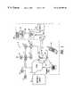
- FIG. 1shows a simplified block diagram of a cellular switching system, its logical entities as well as the relative connection with the public switched telephone network, a private base station contained in a residential premises, and data generators in communication with the private base station;
- FIG. 2shows a high level block diagram of a private base station separated into identifiable circuit sections and a data generator communicating with the private base station through a digital control channel;
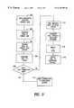
- FIG. 3shows a high level flow chart depicting one example of the invention in operation
- FIG. 4shows a high level block diagram of a private base station visiting location register separated into identifiable circuit sections
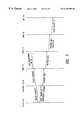
- FIG. 5shows a registration/network update process through which a mobile station gains access to a private base station, in accordance with the invention
- FIG. 6shows a network cancellation process which details how a registration of a mobile station with a private base station is canceled, in accordance with the invention.
- FIG. 7shows a network process which provides an incoming call transaction flow for a mobile station with a private base station, in accordance with the invention
- FIG. 8shows a high level block diagram of the method used when the private base station switches to the wireless cellular telephone network
- FIG. 1there is shown a simplified block diagram of a cellular switching system forming part of a wireless cellular phone network illustrated generally at 9 , its logical entities as well as the relative connection with the public switched telephone network and a private base station, and a premises 20 a having data generators 20 b that collect data from appliances or other premises functions and generates the data back to the private base station 20 .
- the cellular conceptis well known and is described in general in the Bell System Technical Journal , Volume 58, Number 1, January 1979, and specifically in an article entitled The Cellular Concept by V. H. MacDonald, on pages 15 through 41 of this journal, the disclosure which is hereby incorporated by reference.
- MSmobile stations
- PSTNpublic telephone switched network
- BSScellular base station
- HLRhome location register
- VLRvisiting location register
- P-VLRprivate base station visiting location register
- PBSprivate base station
- a subscriber station telephone set 19is illustratively shown connected to the public telephone switched network 14 in a well known manner.
- the private base stationis illustrated as part of a residential premises 20 a , shown with the dotted lines.
- a mobile station 10is shown contained in the residential premises.
- mobile switching center 12is illustratively shown connected to mobile switching center 18 and network operation controller (NOC) 17 .
- the mobile switching center 18is part of the overall cellular systems operation and may similarly have a home location register, a visiting location register, a P-VLR, as well as multiple cellular base stations associated therewith. It is understood that other mobile switching centers also may be part of the cellular system.
- the network operation controllerprovides overall control and thereby ensures that the operation of the whole cellular system is supported and serviced.
- the mobile station 10 and base station 20are designed to operate in a cellular system in accordance with the Telecommunications Industry Association (TIA) Interim Standard (IS)-136, dated December 1994.
- TAATelecommunications Industry Association
- ISInterim Standard
- the mobile switching center 12performs all the switching functions related to call delivery and is interconnected to the public telephone switched network 14 , the home location register 15 , the visiting location register 16 and the cellular base station 13 .
- the home location register 15maintains a data base, profile record and call routing information or a pointer to the call routing information for all mobile stations in a particular assigned home area.
- the visiting location register 16maintains a data base for call routing information or a pointer to the call routing information for those mobile stations which are visiting its assigned area of coverage.
- the private base station visiting location register 30performs the interface functions between a private base station, such as station 20 , and both the home location register 15 and the visiting location register 16 for holding both call routing information and, order or registered position information for the mobile stations that are currently registered with the private base station.
- the private base station visiting location register 30is also responsible for administering spectrum utilization and operations of the private base station 20 .
- the functions for the private base station visiting location register 30may be conveniently summarized as follows:
- the private base station 20qualifies for private (or non-public) mode time-division-multiple-access (TDMA) cellular operation under IS-136 cellular radio interface, which permits a cellular mobile station to register with a private base station to receive or originate calls through a landline connected to the public telephone switched network instead of through a cellular base station, such as cellular base station 13 , connected in the regular public cellular system.
- this radio interfaceprovides the digital control channel in accordance with TIA-IS-136.1 and the traffic channels and control channel in accordance with TIA IS-136.2 for communication with the mobile station.
- a modem interface between the private base station and the private base station visiting location registeralso is supported by the radio interface.
- a monitoring service 50is connected to the public switched telephone network 14 .
- the monitoring service 50receives the collected data from the private base station 20 and calculates any bills or maintains records of the operation of any appliances or other monitored devices from which data is collected.
- the Monitoring service 50could include a service for monitoring water flow, appliance use, power usage, or any similar functions. Any abnormal change in measured data could indicate an emergency or other condition that should be investigated.
- An example of one type of monitoring service that can be used with the present inventionis the AT&T Home Care Services. Data can be generated to this service 50 in real time, allowing continual monitoring of important household or other functions. As will be described later, if a landline connection is cut so that important monitoring ceases, the private base station can switch into the cellular network, generating a call through the cellular network, though the private base station and to the monitoring service.
- the residence 20 aincludes an air conditioner 52 and heater 54 that are connected to data generators 20 b , each connected to a mobile unit 58 .
- the mobile unitsends a similar signal as a cellular mobile unit to the private base station 20 using a communication channel 60 and a digital control channel 62 .
- Datais collected from data generators 20 a and can be transmitted over the digital control channel 62 to the private base station 20 , which can forward the data through a digital control channel 64 to the cellular network.
- the callis then switched through the public switched telephone network 14 to the monitoring service 50 .
- a communication channel 66carries standard communication.
- the base stationcan send data over a landline using a standard line 70 .
- the control channelcould be a subcarrier of the normal telephone frequency.
- the type of private base station usedwill dictate whether a control channel can be used.
- the private base stationalso can include a disc drive or other storage medium ( 72 in FIG.2) that can act as a data collector and store the generated data for future or real time delivery.
- any data collector known by those skilled in the actcan be used in the present invention.
- the private base stationAfter the generated data is received, the private base station initially tries to connect via a landline to the public switched telephone network 14 . If a connection is made, the data is preferably forwarded via the landline through the public switched telephone network to the monitoring service 50 . If a landline connection is not established, the private base station 20 can switch (reverse) and make a call via the cellular circuitry 100 (FIG. 2) to the wireless cellular phone network 9 , which switches the call into the public switched telephone network 14 and to the monitoring service.
- the systemis advantageous because in some circumstances the digital control channel 64 can use time division multiplexing so that the private base station 20 can also be used with a mobile phone, while data is generated to the monitoring service 50 .
- FIG. 3there is illustrated a high level chart illustrating one example of a method that can be used for present invention.
- the reference numerals beginning in the 200 seriesare used.
- a data generatorfirst measures data and information from an appliance located in a residence (Block 200 ). This data is then generated to the mobile unit (Block 202 ), which then transmits the data along a digital control channel to the private base station (Block 204 ). The private base station then generates a call to the public switched telephone network (Block 206 ). If a landline connection is made (Block 208 ), the call is then switched to the monitoring service (Block 210 ).
- the private base stationthen switches into its cellular circuit 100 (Block 212 ) and a call is generated through the wireless cellular phone network (Block 214 ) into the public switched telephone network (Block 216 ) to the monitoring service (Block 218 ).
- a call from the private base station to the wireless cellular phone networkcan transmit data over the digital control channel, which can use time division multiplexing.
- the private base station 20is limited to a very low level of transmitted power of restricting its coverage range to a relative small area. This allows the private base station to reuse the same radio frequency spectrum used by the macro cellular systems as long as the frequency of use selected by the private base station is different from the cell for the regular public or macro cellular system in whose area of coverage the private base station is located.
- the operating frequency spectrum for the private base stationis selected in a way that insures no interference to the macro cellular system. This is achieved by directing the private base station to perform channel scanning and interference measurements before selecting its operating frequencies. While operating in its normal mode awaiting receipt of an incoming call or an off-hook request from a registered mobile station, the private base station 20 continually broadcasts digital control channel information containing its identity and system parameters.
- An IS-136 compliant mobile stationcan search for a private base station's control channel transmission using a number of techniques. One of these may be based on the mobile station's prior knowledge of the private base station's existence. Another may be in response to a mobile station user manually directing the mobile station to search for the private base station. In yet another technique the mobile station, upon finding the control channel of the private base station, automatically goes through a series of controlled procedures to obtain registration with the private base station.
- the private base station 20makes a modem connection to the private base station visiting location register 30 to update the mobile station's temporary line dialing number (TLDN).
- the temporary line dialing numberin this case will be the private base station's landline number (LLN).
- the temporary line dialing numbermay be stored in either the home location register 15 or the visiting location register 16 , and the mobile switching center 12 then accesses this TLDN from this register.
- the private base station 20detects the ring for an incoming call and sends an alerting signal or page to the registered mobile station. Following the mobile station's response to the alerting signal, private base station 20 establishes a traffic channel for the mobile station and generates an off-hook condition to connect the incoming call through the private base station to the mobile station.
- the private base station 20supports the registering of multiple mobile stations and, in accordance with the disclosed embodiment, provides a personalized call delivery feature for each registered mobile station.
- additional information elementsi.e., digits
- a local unique addressis generated at the private base station. This local unique address may be either advantageously generated from the mobile station identification number contained in each mobile station or generated from an ordered position assigned by the private base station for each portable station registered with the private base station.
- the mobile station that registers with the private base station 20is inserted in registered position 1 by the private base station visiting location register 30 , and the second mobile station is inserted in registered position 2 by the private base station visiting location register 30 and so forth.
- This ordered position informationis advantageously treated as the local unique address or a sub-address by the private base station 20 for each mobile station registered with it. A distinct identity of binary digits for each mobile station distinguishing it from all other mobile stations registered with private base station 20 is obtained thereby.
- the private base stationreceives the binary digits describing the order of registered position in the same manner as caller-ID delivery is achieved.
- the ordered position informationis appended to the caller-ID message that accompanies an incoming ring signal or is appended to the time slot allocated for the caller-ID message when such message is not present.
- Switching officesthat provide caller ID messages to a telephone station capable of decoding and storing the incoming telephone number are either shown or described in U.S. Pat. 4,277,649 which issued to D. Sheinbein on Jul. 7, 1981.
- the private base stationalong with the help of a mobile station user's profile stored in the private base station can support additional features like
- FIG. 2Shown in FIG. 2 is a high-level block diagram of private base station 20 separated into identifiable circuit sections.
- a radio frequency (RF) circuit 21performs the radio frequency signal processing. Included in this circuit is a radio frequency receiver section which receives the radio frequency signal from the mobile stations 10 and 11 and, after appropriate filtering and down conversion, produces I and Q signal for an RF CODEC 22 which is connected to the RF circuit 21 .
- a radio frequency transmit section in RF circuitreceives the I and Q signals from the RF CODEC 22 , converts these signals to the appropriate radio frequency range and amplifies them for wireless transmission via antenna 23 .
- the RF CODEC 22performs analog-to-digital (A/D) conversion of the I and Q signals received in the receiver section of the RF circuit 21 and digital-to-analog (D/A) conversion of the I and Q signals provided to the transmitter section of the RF circuit 21 .
- the RF CODEC 22also performs modulation for the transmission path.
- DSPdigital signal processor
- the DSP 23also communicates with a microcontroller 24 for exchanging control messages.
- a user CODEC 25performs conversion of digitally sampled speech signals to analog speech signals and also performs conversion of analog speech signals to digitally sampled speech signals.
- a switch 25 aused in the present invention for switching the private base station into communication with the wireless cellular network 9 for the landline PSTN 14 .
- the switch 25 ais connected to a second cellular circuit indicated generally by 100 , and in parallel with RF unit 21 and a hybrid and line interface circuits interface section 26 which performs the required functions for interfacing the private base station 20 to the public switched telephone network 14 .
- Theseinclude such functions and circuits as, for example, switch-hook operations, hybrid, ring detect, line termination, on/off hook signal interface signals and the like.
- the microcontroller 24performs the call processing functions between the private base station 20 and any registered mobile stations as well as all other control functions that are required for operation of the private base station 20 .
- LEDs 27provide visual feedback to a user who makes entries at the private base station. Buttons 28 connect to the microcontroller 24 and are used in making the entries in the private base station 20 . Once such entry, as described later herein, is that made by the primary user of the base station who direct this base station to register a mobile station for the first time.
- a memory unit 102is connected to the microcontroller 24 and stores the calling numbers received from a landline network when a mobile unit is not able to accept a call.
- the memory unit 102also can store emergency numbers, as well as software that can be used by the private base station microcontroller 24 .
- the microcontroller 24is programmed to work in conjunction with the memory unit 102 so that predefined signaling codes, similar to LASS features in a public network, can be generated by a mobile phone.
- the private base stationreceives signaling codes from the cellular phone to allow signaling functions.
- the memory unitconnects to the second cellular transceiver unit indicated by the dashed lines of 100 and, more particularly, to a dialer unit 104 that generates the calling number to a radio frequency transceiver unit 106 , which connects into an amplifier 108 and second antenna 110 .
- the second cellular transceiver unit 100works closely in parallel to the RF unit 21 and is operatively connected thereto to work on similar frequencies.
- the second transceiver unit 100allows greater power generation for operation with the cellular network 9 .
- a data generator 20 bis connected to an appliance such as a heater 54 in a premises.
- the data generator 20 bcan be hardwired to a mobile unit 58 , or alternately, the data generator can generate infrared or ultrasonic data signals to a mobile unit 58 .
- the mobile unit 58in turn can be hardwired to the private base station or it can generate signals, such as through a digital control channel to the receiving antenna 23 of the private base station.
- an emergency button 120typically located on the private base station connects to the microcontroller so that upon depression of that emergency button 120 , a stored emergency number is dialed and then sent to the cellular network 9 .
- the amplifier 108provides the added power for the private base station to communicate with the cellular network. Additionally, the mobile units 10 , 11 include emergency buttons 10 a , 11 a that upon their depression, activate the dialer 104 for generating a dialing sequence of emergency numbers stored within the memory unit 102 .
- the private base stationcan be designed so that it can be mobile and used as a cellular unit if an RJ-11 jack is not available for connecting the unit into the wired public-switch telephone network 14 .
- the private base stationcan be programmed so that any stored emergency number can be dialed through the wireless cellular phone network upon receiving an emergency signal whether from the pushing of the emergency button on the mobile telephone or private base station. Additionally, the stored emergency number can be dialed through the landline.
- FIG. 8illustrates a high level flow chart showing an example of the operation of the system.
- the mobile telephone 10When the mobile station 10 approaches the residential premises 20 a containing the private base station 20 , the mobile telephone 10 automatically registers with the private base station (Block 100 ). At the time of registration, a call-forwarding signal is sent from the private base station through the landline and to the cellular network requesting all cellular phone calls made to mobile station 10 to be delivered to the private base station via the land-line (Block 202 ).
- the memory unit 102stores various Calling Party Numbers (CPN) (Block 204 ).
- the mobile operatorthen activates a LASS feature, dialing a service code that is sent to the private base station, i.e., AUTO CALLBACK - STAR 69 (*69).
- the private base stationidentifies this service code (Block 208 ) and retrieves the most recent incoming calling party number (Block 210 ) and then sends those digits to the dialer unit 104 connected to the RF unit 106 and amp 108 .
- the switch 25 ais activated so that the second transceiver unit 100 transmits the digits over the air interface (Block 212 ).
- the networksends the signaling information (receive digits) to a MSC 12 and then to a service node (Block 214 ).
- the service modeidentifies a feature code and instructs the network to set up the call if the called party's line is idle (Block 216 ). If the called party's line is busy, the service node may instruct the network to monitor the status of the called party's line for a definite period of time (Block 218 ). As soon as this service node detects that the called party's line is idle, it instructs the network to set up the call through a normal call set up procedure through the wireless network (Block 220 ).
- the emergency buttons on either the private base station or mobile unitcan be pushed to generate a signal.
- the switching of the private base station into the cellular network upon receiving signaling codeswill occur preferably when only one mobile station is registered with the private base station. However, the operation does not have to operate only in this fashion.
- FIG. 4 of the drawingthere is shown a general block diagram of a private base station visiting location register 30 .
- This private base station visiting location register 30may be geographically located away from or co-located with either a visiting location register or a home location register, with which it receives and provides private base station information.
- the functions provided by the private base station visiting location register 30also may be integrated into a visiting location register or a home location register, and such operation is hereby anticipated.
- the elements employed in the private base station registerare computer 300 , modem 330 , control interface modules 340 , 341 and 342 , disk storage unit 343 and a plurality of databases 310 , 330 , 335 and 340 .
- the communications modem pool 330typically provides data communication between multiple private base stations and the private base station visiting location register through the public telephone switched network.
- modem protocolssuch as V.22, V.22 bis or Bell 212 are all suitable for communications between the modem pool 330 and a private base station through the public telephone switched network.
- a packet data protocolprovide the two-way communications requirement. For example, an X.25 packet data protocol may be used in providing this communication.
- ISDNintegrated services digital network
- the ISDN lines 332are connected directly to the communications interface module 340 and enable the private base station visiting location register 30 to maintain communications between the home location register 15 and the visiting location register 16 .
- Protocols that may be used in providing this ISDN communicationmay be, by way of example, either IS-41 or SS7 which are well-known in the industry.
- the data signals received by modem pool 330 over both communications lines 331 and 332are provided to a communications interface module 340 .
- the data received by the interface module 340is couple to the input/output control module 341 for processing by the computer 300 or for input to or accessing one or more of a series of databases, illustratively shown as database 310 , 330 , 335 and 345 , as well as a disk storage medium 343 , via the peripheral control interface module 342 .
- the peripheral control interface module 342interfaces the computer 300 and communications lines to the appropriate ones of the series of databases. or data files in accordance with the service or task being performed.
- Each one of the series of databases 310 , 330 , 335 and 345contain specific information.
- the database 310contains information of frequency allocations of surrounding cellular systems.
- Database 330contains information of private base stations operating parameters determined by the private base station's location. Examples of a private base station operating parameters are its operating frequency, transmitted power, authorization time, and the like.
- Database 335contains mobile station order of registered position information with the private base station and also private base station profiles. Examples of private base station profiles are “Call Waiting” and “Caller ID” that are provided by the public telephone switched network, and also any private base station location register 30 . It is to be understood that other databases providing additional services or tasks also may be interfaced with the computer 300 via the peripheral control interface module 342 .
- Disk storage 343contains operational information that is applicable to the cellular system in general, such as operation parameters that are required for interfacing the private base station visiting location register with home location register and visiting location register.
- a data processor 304Contained in the computer 300 are a data processor 304 , random access memory (RAM) 305 and read only memory (ROM) 306 .
- This processor 304responds to data input into input/output control mode 341 . And with input from random access memory 305 and read only memory 306 , processor 304 also provides the data to the processor bus 301 for facilitating data exchanges between the plurality of databases and the communications interface module 340 via the peripheral control interface module 342 .
- a registration/network update processthough which a mobile station, such as mobile station 10 , gains access to a private base station, such as private base station 20 .
- the private base stationinitially authorizes the mobile station to obtain registration through it. After such initial authorization, the mobile station remains on the digital control channel.
- the private base stationthen seeks authorization for registration of the mobile station from the private base station visiting location register.
- the camping of the mobile station on the digital control channelcan be terminated by the host private base station if proper authorization from the private base station visiting location is not obtained.
- the home location register 15 or visiting location register 16is provided a call forwarding number from the private base station visiting location register (the private base station's LLN) for the mobile station.
- the registration processbegins when an authorized mobile station sends a test registration (registration sequence) to the private base station.
- This registration/network update processis summarized below and also illustrated in FIG. 5 .
- the mobile stationsends a test registration which includes the mobile station's identification (mobile station ID) and the mobile station's electronic serial number (ESN) to the private base station.
- mobile station IDmobile station ID
- ESNelectronic serial number
- the private base stationsends back a registration accept signal to the mobile station.
- the private base stationestablishes a modem call to the P-VLR.
- the private base stationperforms an authentication task to satisfy P-VLR's requirements.
- the P-VLRsends and acknowledge or negative acknowledge (ACK/NACK) to the private base station in response.
- ACK/NACKacknowledge or negative acknowledge
- Receipt of the NACK responsecancels further transaction by the private base station and the mobile station registration attempt will be canceled.
- the private base stationmay also be directed to shut down and retry registration at some subsequent time.
- the private base stationFollowing receipt of an ACK, the private base station performs a network update when the mobile station ID, mobile station ESN, landline number as well as the order of registered position obtained for the mobile station are sent to the P-VLR.
- the order of registered positionuniquely identifies the mobile station among other currently registered mobile stations within the private base station.
- the P-VLRsends a Registration Notification to either the HLR or VLR. If the mobile station is in its home cellular coverage area, the notification will be directed to the HLR. Otherwise, the VLR will receive the notification. In the later case the HLR for the mobile station's home area will also be notified of the registration notification.
- the HLR or VLRsends an ACK or NACK to the P-VLR. If an NACK is send, the denial could depend on a number of factors that depend on the service provider. For example, the provider may find that the mobile station does not have a valid service with it, or a second example could be that the mobile station does not have a valid mobile ID number, or it could be any other similar reason.
- the P-VLRsends corresponding ACK or NACK to the private base station.
- the modem callis terminated.
- the private base stationIf an NACK is sent to the private base station by the P-VLR, the private base station sends a registration cancellation to the mobile station.
- the first mobile station registered with the private base station in this processis allocated the position location number 1 .
- the subsequent mobile stations registered with the private base stationare given correspondingly increasing numbers.
- a private base stationare given correspondingly increasing numbers.
- a private base stationcan typically support, by way of example, 10 such registrations, although more or less may be desired and the private base station suitably configured to accommodate different numbers. If a new mobile station registration request is properly received which exceeds the number then allocated for supporting registered mobile stations, the least used mobile registration number will be vacated to make room for the new one. Once registered, the mobile station does not need to re-register in this particular sense. Whenever the mobile station attempts to obtain subsequent registration for service with the private base station, the registration location number for the mobile station remains unchanged, assuming some minimal level of periodic use.
- the private base stationalways sends to the private base station visiting location register 30 the same registration location number for a particular mobile station. Also, it is understandable that the information exchange for a new mobile station registration will be much extensive when compared to its subsequent registration with the private base station.
- FIG. 6there is shown a network cancellation process in which a pre-established and existing registration of a mobile station with a private base station is canceled or terminated.
- the network cancellation processbegins when an authorized mobile station moves out of the private base station's coverage area or the mobile station's power is turned off. When the mobile station moves out of the coverage area of the private base station, the resulting loss of communication from the mobile station is detected by the private base station. Also, when the mobile station's power is turned off, the mobile station performs power-down registration. When either of these two events occurs, the network cancellation process is executed by the private base station. Through this process, any cal forwarding to the private base station's land line number for the mobile station is cancelled.
- This network cancellation processis summarized below and also illustrated in FIG. 6 .
- the mobile stationperforms power-down registration.
- the private base stationestablishes a modem call to the P-VLR.
- the private base stationperforms an authentication task to satisfy the P-VLR's requirements.
- the P-VLRsends either an ACK or a NACK in response.
- the private base stationcancels further transactions for this particular mobile station.
- the private base stationalso may be directed to shut down or to attempt a retry later at authentication.
- the private base stationperforms network cancellation by sending the mobile station ID and the mobile station ESN to cancel call forwarding of telephone calls to the mobile station which has either moved out of the coverage area or whose power is turned off.
- the P-VLRsends a mobile station inactive signal to HLR/VLR.
- the HLR/VLRthen sends either an ACK or a NACK to the P-VLR.
- the P-VLRsends a corresponding ACK or NACK to the private base station.
- the modem callis terminated.
- the user of a mobile stationmay elect to terminate communication with a private base station and reenter his or her mobile station into the cellular system.
- a mobile stationmay exercise this option, when, for example, service at the private base station is not available due to the single land line connection to the public telephone switched network being occupied by another mobile station communicating through the shared private base station.
- a mobile station usermay reenter the cellular system simply by, for example, pressing a cellular service button which executes a process wherein service with the private base station is terminated and service with the cellular service provider in the public cellular system is established.
- cellular serviceis established with, for example, cellular base station 13 , shown in FIG. 6, a network update is performed by home location register 15 is the mobile station is located in its home coverage area or by visiting location register 16 if the mobile station is outside its home coverage area.
- home location register 15 or visiting location register 16informs private base station visiting location register 30 that the identified mobile station has returned to the cellular system.
- the private base station visiting location register 30then stores a mobile station inactive signal for the identified mobile station effectively inactivating or cancelling its call forwarding information.
- the network cancellation process described in FIG. 6is attempted by the private base station. since call forwarding for the identified mobile station has already been cancelled int he private base station visiting location register 30 , in this instance by the mobile station reentering the cellular system, executing this process only confirms that the mobile station is presently not active with the private base station 20 .
- FIG. 7there is shown a network process which provides an incoming call transaction flow for a mobile station registered with a private base station. All incoming calls for each one of the mobile stations registered with the private base station will be routed to the private base station's landline number.
- the call transaction flowis summarized below and with reference to FIG. 7 .
- a call origination and the dialed mobile station IDare received from the public switched telephone network and routed to the MSC.
- the MSCmay receive the call origination and the dialed mobile station ID from the cellular base station 13 in the public cellular system.
- the MSCsends a route request to the mobile station's HLR (or to the VLR when the mobile station is a visiting station).
- the HLRforwards the Route Request to the corresponding P-VLR which contains the registration information for the mobile station.
- the P-VLRreturns the TLDN as well as the order of registered position to the HLR (or to the VLR when the mobile station is a visiting station) as part of the routing information.
- the order of registered positionis defined as a sub-address for the mobile station.
- the HLRadds mobile station ID and mobile station ESN to the routing information and returns the location request to the MSC which, in turn, forwards this information to the PSTN.
- the callis delivered by the PSTN, which may include caller ID, to the LLN, the sub-address containing order of registered position is also sent along with the caller ID to the private base station.
- the private base stationthen sends a page to the mobile station along with the caller ID.
- the paged mobile stationis the one which corresponds to the order of registered position.
- the private base stationis able to advantageously offer various intelligent features which are personalized according to customer needs. For example, a calling party may have his or her name displayed on the mobile station for the convenient of the user at the mobile station.
- the user of a registered mobile stationis provided with a separate memory space allocated at the private base station to store a directory of phone numbers with names respectively associated with the telephone numbers.
- a calling party having a number that matches with one of the stored numbers in the directorywill have his or her name sent to the mobile station by the private base station for display instead of the telephone phone number.
- the private base stationis able to provide distinctive alerting for a registered mobile station.
- the user of a registered mobile stationcan have, for example, a distinctive ringing sound (chosen from a group of ring sounds) associated with a particular calling party stored in his or her directory. Distinctive ringing is illustratively described in U.S. Pat. 4,995,075.
- the private base stationis able alert the mobile station using the distinct ringing sound.
- the private base stationis also able to provide a number of other advantageous functions based on obtaining an order of registered position for each of mobile stations.
- Featuressuch as call blocking, an incoming call log, such as described in U.S. Pat. 5,386,460, and a telephone answering function with personalized mailboxes are easily provided.
- call blockingthe user has a choice of blocking an incoming call which number matches one of specified numbers stored in the directory.
- the incoming call logis advantageously provided in the private base station for each of the registered mobile station users.
- the private base stationallows personalized greetings to be stored in a mailbox for each of the registered mobile stations. When an incoming call is directed to a particular mobile station and the user of this station does not respond, this personalized greeting is played to the calling party by the private base station.
- the advantages and beneficial features of the present inventionnow allow a private base station to collect data generated from data collectors positioned in a premises for transmission in real time to a monitoring service.
- the datacan be continually generated and transmitted via the landline for monitoring important household or other functions. If the landline is cut, the private base station can switch (reverse) and generate a call through the wireless cellular network to the monitoring service.
Landscapes
- Engineering & Computer Science (AREA)
- Signal Processing (AREA)
- Mobile Radio Communication Systems (AREA)
Abstract
Description
Claims (19)
Priority Applications (3)
| Application Number | Priority Date | Filing Date | Title |
|---|---|---|---|
| US08/768,371US6169895B1 (en) | 1996-12-17 | 1996-12-17 | Landline-supported private base station for collecting data and switchable into a cellular network |
| PCT/US1997/021848WO1998027764A2 (en) | 1996-12-17 | 1997-12-01 | Landline-supported private base station for collecting data and switchable into a cellular network |
| TW086118807ATW358278B (en) | 1996-12-17 | 1997-12-12 | Landline-supported private base station for collecting data and switchable into a cellular network |
Applications Claiming Priority (1)
| Application Number | Priority Date | Filing Date | Title |
|---|---|---|---|
| US08/768,371US6169895B1 (en) | 1996-12-17 | 1996-12-17 | Landline-supported private base station for collecting data and switchable into a cellular network |
Publications (1)
| Publication Number | Publication Date |
|---|---|
| US6169895B1true US6169895B1 (en) | 2001-01-02 |
Family
ID=25082299
Family Applications (1)
| Application Number | Title | Priority Date | Filing Date |
|---|---|---|---|
| US08/768,371Expired - LifetimeUS6169895B1 (en) | 1996-12-17 | 1996-12-17 | Landline-supported private base station for collecting data and switchable into a cellular network |
Country Status (3)
| Country | Link |
|---|---|
| US (1) | US6169895B1 (en) |
| TW (1) | TW358278B (en) |
| WO (1) | WO1998027764A2 (en) |
Cited By (49)
| Publication number | Priority date | Publication date | Assignee | Title |
|---|---|---|---|---|
| US6311060B1 (en)* | 1998-05-21 | 2001-10-30 | Cellemetry Llc | Method and system for registering the location of a mobile cellular communications device |
| US20020016184A1 (en)* | 2000-08-03 | 2002-02-07 | Alcatel | Automatic method of managing network services |
| US6351649B1 (en)* | 1998-03-31 | 2002-02-26 | Kdd Corporation | Mobile communication system |
| US20020061766A1 (en)* | 2000-11-22 | 2002-05-23 | Hijin Sato | Base station for use in multi-network connection communication system and its connecting method |
| US20020137508A1 (en)* | 2001-03-23 | 2002-09-26 | Kuipers Paulus Gerardus Martinus | System for communicating with terminals at remote locations |
| US6535730B1 (en) | 1998-12-31 | 2003-03-18 | At&T Corp. | Wireless centrex conference call adding a party |
| US20030054796A1 (en)* | 2001-09-17 | 2003-03-20 | Hitachi, Ltd. | Charging method and terminal equipment in the information and communication network system |
| US20030081735A1 (en)* | 2001-08-27 | 2003-05-01 | Emory Thomas M. | System and method for detecting and reporting defective telephone lines and alarm events |
| US6574470B1 (en) | 1998-12-31 | 2003-06-03 | At&T Corp. | Programmable ring-call forwarding in a wireless centrex services system |
| US6587683B1 (en) | 1998-12-31 | 2003-07-01 | At&T Corp. | Unconditional call forwarding in a wireless centrex services system |
| US6591115B1 (en) | 1998-12-31 | 2003-07-08 | At&T Corp. | Wireless centrex call hold |
| US6606493B1 (en) | 1998-12-31 | 2003-08-12 | At&T Corp. | Wireless centrex conference call deleting a party |
| US6606505B1 (en) | 1998-12-31 | 2003-08-12 | At&T Corp. | Wireless centrex call screen |
| US6618600B1 (en)* | 1998-12-31 | 2003-09-09 | At&T Corp. | Distinctive ringing in a wireless centrex system |
| US6631258B1 (en) | 1998-12-31 | 2003-10-07 | At&T Corp. | Busy call forwarding in a wireless centrex services system |
| US6643512B1 (en)* | 1999-09-14 | 2003-11-04 | Motorola, Inc. | Method and apparatus for spanning operation of a cellular telephone |
| US6643507B1 (en) | 1998-12-31 | 2003-11-04 | At&T Corp. | Wireless centrex automatic callback |
| US6654603B1 (en) | 1998-12-31 | 2003-11-25 | At&T Corp. | Call waiting in a wireless centrex system |
| US6654615B1 (en) | 1998-12-31 | 2003-11-25 | Albert Chow | Wireless centrex services |
| US20040048624A1 (en)* | 2002-09-10 | 2004-03-11 | Young-Uk Ko | Method for informing mobile communication terminal of entrance into specific service network in mobile communication system and method for changing incoming call indication mode to vibration or silent mode |
| US6711401B1 (en) | 1998-12-31 | 2004-03-23 | At&T Corp. | Wireless centrex call return |
| US6738615B1 (en) | 1998-12-31 | 2004-05-18 | At&T Corp. | Wireless centrex caller ID |
| US6738647B1 (en)* | 1999-04-23 | 2004-05-18 | Numerex Corporation | Method and system for expanding the data payload of data messages transported via a cellular network control channel |
| US6745025B1 (en) | 1998-12-31 | 2004-06-01 | At&T Corp. | Time-of-day call forwarding in a wireless centrex services system |
| US6748239B1 (en)* | 1999-12-01 | 2004-06-08 | Ericsson Inc. | Methods and systems for communicating service codes over a PSTN using single stage dialing |
| US20040124976A1 (en)* | 2002-09-12 | 2004-07-01 | Nambi Seshadri | Detecting communications disconnect and enabling wireless emergency call |
| US6771953B1 (en) | 1998-12-31 | 2004-08-03 | At&T Corp. | Wireless centrex call transfer |
| US20040157597A1 (en)* | 1999-09-20 | 2004-08-12 | Cellemetry, Llc | System for communicating messages via a forward overhead control channel for a programmable logic control device |
| US6785560B1 (en) | 1998-12-31 | 2004-08-31 | At&T Corp. | Speed calling in a wireless centrex system |
| US6819945B1 (en) | 1998-12-31 | 2004-11-16 | At&T Corp. | Wireless centrex feature activation/deactivation |
| US20040228303A1 (en)* | 2003-04-30 | 2004-11-18 | Kelly Michael R. | Canceling stations between protocols |
| US20050043011A1 (en)* | 1999-09-20 | 2005-02-24 | Numerex Corp. | Method and system for refining vending operations based on wireless data |
| US20050101317A1 (en)* | 1999-10-29 | 2005-05-12 | Cellemetry, Llc | Interconnect system and method for multiple protocol short message services |
| US7123906B1 (en)* | 2003-10-17 | 2006-10-17 | Verizon Communications Inc. | Integrated telephony service |
| US20070058545A1 (en)* | 2005-07-19 | 2007-03-15 | Nookala Sriram N | Systems, methods, and apparatus for quality of service processing |
| US7245928B2 (en) | 2000-10-27 | 2007-07-17 | Cellemetry, Llc | Method and system for improved short message services |
| US7272494B2 (en) | 2002-03-28 | 2007-09-18 | Numerex Investment Corp. | Communications device for conveying geographic location information over capacity constrained wireless systems |
| US7323970B1 (en) | 2004-01-21 | 2008-01-29 | Numerex Corporation | Method and system for remote interaction with a vehicle via wireless communication |
| US20080045269A1 (en)* | 2006-05-17 | 2008-02-21 | Numerex Corp. | System and method for prolonging wireless data product's life |
| US20080076420A1 (en)* | 2006-09-22 | 2008-03-27 | Amit Khetawat | Method and apparatus for user equipment registration |
| US20080076411A1 (en)* | 2006-09-22 | 2008-03-27 | Amit Khetawat | Method and apparatus for determining rove-out |
| US20080076393A1 (en)* | 2006-09-22 | 2008-03-27 | Amit Khetawat | Method and apparatus for securing communication between an access point and a network controller |
| US20080287109A1 (en)* | 2007-02-06 | 2008-11-20 | Numerex Corporation | Service escrowed transportable wireless event reporting system |
| US20090287456A1 (en)* | 2008-05-13 | 2009-11-19 | Steve Tran | Distributed Sensor System |
| US20100267389A1 (en)* | 2001-02-26 | 2010-10-21 | Gallagher Michael D | Apparatus for supporting the handover of a telecommunication session between a licensed wireless system and an unlicensed wireless system |
| US7890117B1 (en)* | 2000-03-09 | 2011-02-15 | Nortel Networks Limited | Automatic remote communication using network telephony |
| US7903625B1 (en) | 2008-12-03 | 2011-03-08 | Sprint Spectrum L.P. | Internet-base-station-based traffic offload analysis |
| US20110237238A1 (en)* | 2010-03-26 | 2011-09-29 | Microsoft Corporation | Cellular service with improved service availability |
| US8150344B1 (en) | 2008-02-19 | 2012-04-03 | Sprint Spectrum L.P. | Method and system of planning a wireless telecommunication network |
Families Citing this family (3)
| Publication number | Priority date | Publication date | Assignee | Title |
|---|---|---|---|---|
| GB2357389B (en)* | 1999-12-10 | 2002-02-13 | Telemetrics Ltd | Telemetry systems |
| GB2366132B (en)* | 2000-03-24 | 2004-11-24 | Abb Metering Ltd | Transmission of information in a utility commodity system |
| ES2172456B1 (en)* | 2000-12-22 | 2003-12-16 | Fernandez Andres Molina | REMOTE COUNTER READING SYSTEM. |
Citations (30)
| Publication number | Priority date | Publication date | Assignee | Title |
|---|---|---|---|---|
| US3503061A (en) | 1966-07-20 | 1970-03-24 | Gen Electric | Telemetering system with optoelectronic coupling between transmission line and meter |
| US3808372A (en) | 1972-11-03 | 1974-04-30 | Chronometrics Inc | Automatic timekeeping and recorder unit |
| US3911446A (en) | 1974-03-26 | 1975-10-07 | Chronometrics Inc | Automatic timekeeping and accounting unit |
| US3943526A (en) | 1974-08-19 | 1976-03-09 | Chronometrics, Inc. | Automatic timekeeping and accounting unit |
| US4071710A (en) | 1975-11-05 | 1978-01-31 | Roy Burnett | Communication-recorder system |
| US4639728A (en) | 1985-09-16 | 1987-01-27 | Sangamo Weston, Inc. | Method of and system for accumulating verifiable energy demand data from remote electricity meters |
| US4682169A (en) | 1985-09-16 | 1987-07-21 | Sangamo Weston, Inc. | Method of and system for accumulating verifiable energy demand data from remote electricity meters |
| US4827461A (en) | 1987-09-17 | 1989-05-02 | Dictaphone Corporation | Universal telecommunications audio coupling device |
| US4862509A (en) | 1987-10-13 | 1989-08-29 | Genvention, Inc. | Portable recording system for telephone conversations |
| US4893332A (en) | 1986-05-12 | 1990-01-09 | Aquatrol Corporation | Low-powered remote sensor |
| CH676398A5 (en) | 1989-08-30 | 1991-01-15 | Landis & Gyr Betriebs Ag | Cordless transmission system for information between equipment - uses remote transmission between items in building and telephone network |
| US4989230A (en) | 1988-09-23 | 1991-01-29 | Motorola, Inc. | Cellular cordless telephone |
| US5127042A (en) | 1988-09-23 | 1992-06-30 | Motorola, Inc. | Cellular cordless telephone |
| US5161182A (en) | 1989-04-04 | 1992-11-03 | Sparton Corporation | Remote meter reading method and apparatus |
| US5239575A (en) | 1991-07-09 | 1993-08-24 | Schlumberger Industries, Inc. | Telephone dial-inbound data acquisition system with demand reading capability |
| US5311581A (en) | 1989-04-04 | 1994-05-10 | Sparton Corporation | Remote meter reading method and apparatus |
| US5353331A (en) | 1992-03-05 | 1994-10-04 | Bell Atlantic Network Services, Inc. | Personal communications service using wireline/wireless integration |
| WO1994024805A1 (en) | 1993-04-13 | 1994-10-27 | Nizar Ladha | Alarm panel with cellular telephone backup |
| US5369691A (en) | 1993-03-04 | 1994-11-29 | Utilex, Inc. | Telephonic information communication method and apparatus |
| US5442680A (en) | 1992-06-23 | 1995-08-15 | Motorola, Inc. | Dual system cellular cordless radiotelephone apparatus with sub-data channel timing monitor |
| WO1995023488A1 (en) | 1994-02-24 | 1995-08-31 | Gte Mobile Communications Service Corporation | Multiple mode personal wireless communications system |
| WO1995024106A1 (en) | 1994-03-03 | 1995-09-08 | Ericsson Inc. | Secure radio personal communications system and method |
| US5526403A (en)* | 1993-01-19 | 1996-06-11 | Novatel Communications Ltd. | Wireline interface for cellular telephone |
| US5546444A (en)* | 1994-03-11 | 1996-08-13 | Bellsouth Corporation | Methods and apparatus for communicating data via a cellular network control channel |
| US5608778A (en)* | 1994-09-22 | 1997-03-04 | Lucent Technologies Inc. | Cellular telephone as an authenticated transaction controller |
| US5675371A (en)* | 1995-10-27 | 1997-10-07 | Location Science Corporation | Apparatus for monitoring cable television system remote equipment performance and status using a cell modem |
| US5675629A (en)* | 1995-09-08 | 1997-10-07 | At&T | Cordless cellular system base station |
| US5745852A (en)* | 1995-07-31 | 1998-04-28 | Lucent Technologies | Land-line supported private base station operable in a cellular system |
| US5892758A (en)* | 1996-07-11 | 1999-04-06 | Qualcomm Incorporated | Concentrated subscriber wireless remote telemetry system |
| US6035193A (en)* | 1996-06-28 | 2000-03-07 | At&T Wireless Services Inc. | Telephone system having land-line-supported private base station switchable into cellular network |
- 1996
- 1996-12-17USUS08/768,371patent/US6169895B1/ennot_activeExpired - Lifetime
- 1997
- 1997-12-01WOPCT/US1997/021848patent/WO1998027764A2/enactiveApplication Filing
- 1997-12-12TWTW086118807Apatent/TW358278B/ennot_activeIP Right Cessation
Patent Citations (33)
| Publication number | Priority date | Publication date | Assignee | Title |
|---|---|---|---|---|
| US3503061A (en) | 1966-07-20 | 1970-03-24 | Gen Electric | Telemetering system with optoelectronic coupling between transmission line and meter |
| US3808372A (en) | 1972-11-03 | 1974-04-30 | Chronometrics Inc | Automatic timekeeping and recorder unit |
| US3911446A (en) | 1974-03-26 | 1975-10-07 | Chronometrics Inc | Automatic timekeeping and accounting unit |
| US3943526A (en) | 1974-08-19 | 1976-03-09 | Chronometrics, Inc. | Automatic timekeeping and accounting unit |
| US4071710A (en) | 1975-11-05 | 1978-01-31 | Roy Burnett | Communication-recorder system |
| US4639728A (en) | 1985-09-16 | 1987-01-27 | Sangamo Weston, Inc. | Method of and system for accumulating verifiable energy demand data from remote electricity meters |
| US4682169A (en) | 1985-09-16 | 1987-07-21 | Sangamo Weston, Inc. | Method of and system for accumulating verifiable energy demand data from remote electricity meters |
| US4893332A (en) | 1986-05-12 | 1990-01-09 | Aquatrol Corporation | Low-powered remote sensor |
| US4827461A (en) | 1987-09-17 | 1989-05-02 | Dictaphone Corporation | Universal telecommunications audio coupling device |
| US4862509A (en) | 1987-10-13 | 1989-08-29 | Genvention, Inc. | Portable recording system for telephone conversations |
| US4989230A (en) | 1988-09-23 | 1991-01-29 | Motorola, Inc. | Cellular cordless telephone |
| US5127042A (en) | 1988-09-23 | 1992-06-30 | Motorola, Inc. | Cellular cordless telephone |
| US5463674A (en) | 1988-09-23 | 1995-10-31 | Motorola, Inc. | Cellular cordless telephone which polls information in a memory to determine a pre-selected preference and a stored availability of call forwarding |
| US5161182A (en) | 1989-04-04 | 1992-11-03 | Sparton Corporation | Remote meter reading method and apparatus |
| US5311581A (en) | 1989-04-04 | 1994-05-10 | Sparton Corporation | Remote meter reading method and apparatus |
| CH676398A5 (en) | 1989-08-30 | 1991-01-15 | Landis & Gyr Betriebs Ag | Cordless transmission system for information between equipment - uses remote transmission between items in building and telephone network |
| US5239575A (en) | 1991-07-09 | 1993-08-24 | Schlumberger Industries, Inc. | Telephone dial-inbound data acquisition system with demand reading capability |
| US5353331A (en) | 1992-03-05 | 1994-10-04 | Bell Atlantic Network Services, Inc. | Personal communications service using wireline/wireless integration |
| US5469496A (en) | 1992-03-05 | 1995-11-21 | Bell Atlantic Network Services, Inc. | Personal communications service using wireline/wireless integration |
| US5442680A (en) | 1992-06-23 | 1995-08-15 | Motorola, Inc. | Dual system cellular cordless radiotelephone apparatus with sub-data channel timing monitor |
| US5526403A (en)* | 1993-01-19 | 1996-06-11 | Novatel Communications Ltd. | Wireline interface for cellular telephone |
| US5369691A (en) | 1993-03-04 | 1994-11-29 | Utilex, Inc. | Telephonic information communication method and apparatus |
| WO1994024805A1 (en) | 1993-04-13 | 1994-10-27 | Nizar Ladha | Alarm panel with cellular telephone backup |
| US5517547A (en)* | 1993-04-13 | 1996-05-14 | Ladha; Nizar | Alarm panel with cellular telephone backup |
| WO1995023488A1 (en) | 1994-02-24 | 1995-08-31 | Gte Mobile Communications Service Corporation | Multiple mode personal wireless communications system |
| WO1995024106A1 (en) | 1994-03-03 | 1995-09-08 | Ericsson Inc. | Secure radio personal communications system and method |
| US5546444A (en)* | 1994-03-11 | 1996-08-13 | Bellsouth Corporation | Methods and apparatus for communicating data via a cellular network control channel |
| US5608778A (en)* | 1994-09-22 | 1997-03-04 | Lucent Technologies Inc. | Cellular telephone as an authenticated transaction controller |
| US5745852A (en)* | 1995-07-31 | 1998-04-28 | Lucent Technologies | Land-line supported private base station operable in a cellular system |
| US5675629A (en)* | 1995-09-08 | 1997-10-07 | At&T | Cordless cellular system base station |
| US5675371A (en)* | 1995-10-27 | 1997-10-07 | Location Science Corporation | Apparatus for monitoring cable television system remote equipment performance and status using a cell modem |
| US6035193A (en)* | 1996-06-28 | 2000-03-07 | At&T Wireless Services Inc. | Telephone system having land-line-supported private base station switchable into cellular network |
| US5892758A (en)* | 1996-07-11 | 1999-04-06 | Qualcomm Incorporated | Concentrated subscriber wireless remote telemetry system |
Non-Patent Citations (1)
| Title |
|---|
| PCT International Search Report, PCT/US97/21848, Mailed Aug. 7, 1998 |
Cited By (95)
| Publication number | Priority date | Publication date | Assignee | Title |
|---|---|---|---|---|
| US6351649B1 (en)* | 1998-03-31 | 2002-02-26 | Kdd Corporation | Mobile communication system |
| US6311060B1 (en)* | 1998-05-21 | 2001-10-30 | Cellemetry Llc | Method and system for registering the location of a mobile cellular communications device |
| US6654615B1 (en) | 1998-12-31 | 2003-11-25 | Albert Chow | Wireless centrex services |
| US6771953B1 (en) | 1998-12-31 | 2004-08-03 | At&T Corp. | Wireless centrex call transfer |
| US6785560B1 (en) | 1998-12-31 | 2004-08-31 | At&T Corp. | Speed calling in a wireless centrex system |
| US6535730B1 (en) | 1998-12-31 | 2003-03-18 | At&T Corp. | Wireless centrex conference call adding a party |
| US6745025B1 (en) | 1998-12-31 | 2004-06-01 | At&T Corp. | Time-of-day call forwarding in a wireless centrex services system |
| US6738615B1 (en) | 1998-12-31 | 2004-05-18 | At&T Corp. | Wireless centrex caller ID |
| US6574470B1 (en) | 1998-12-31 | 2003-06-03 | At&T Corp. | Programmable ring-call forwarding in a wireless centrex services system |
| US6587683B1 (en) | 1998-12-31 | 2003-07-01 | At&T Corp. | Unconditional call forwarding in a wireless centrex services system |
| US6591115B1 (en) | 1998-12-31 | 2003-07-08 | At&T Corp. | Wireless centrex call hold |
| US6606493B1 (en) | 1998-12-31 | 2003-08-12 | At&T Corp. | Wireless centrex conference call deleting a party |
| US6606505B1 (en) | 1998-12-31 | 2003-08-12 | At&T Corp. | Wireless centrex call screen |
| US6618600B1 (en)* | 1998-12-31 | 2003-09-09 | At&T Corp. | Distinctive ringing in a wireless centrex system |
| US6631258B1 (en) | 1998-12-31 | 2003-10-07 | At&T Corp. | Busy call forwarding in a wireless centrex services system |
| US6711401B1 (en) | 1998-12-31 | 2004-03-23 | At&T Corp. | Wireless centrex call return |
| US6643507B1 (en) | 1998-12-31 | 2003-11-04 | At&T Corp. | Wireless centrex automatic callback |
| US6654603B1 (en) | 1998-12-31 | 2003-11-25 | At&T Corp. | Call waiting in a wireless centrex system |
| US6819945B1 (en) | 1998-12-31 | 2004-11-16 | At&T Corp. | Wireless centrex feature activation/deactivation |
| US6738647B1 (en)* | 1999-04-23 | 2004-05-18 | Numerex Corporation | Method and system for expanding the data payload of data messages transported via a cellular network control channel |
| US6643512B1 (en)* | 1999-09-14 | 2003-11-04 | Motorola, Inc. | Method and apparatus for spanning operation of a cellular telephone |
| US8214247B2 (en) | 1999-09-20 | 2012-07-03 | Numerex Corp. | Methods and system for managing vending operations based on wireless data |
| US20040157597A1 (en)* | 1999-09-20 | 2004-08-12 | Cellemetry, Llc | System for communicating messages via a forward overhead control channel for a programmable logic control device |
| US8126764B2 (en) | 1999-09-20 | 2012-02-28 | Numerex, Corporation | Communication of managing vending operations based on wireless data |
| US20050043011A1 (en)* | 1999-09-20 | 2005-02-24 | Numerex Corp. | Method and system for refining vending operations based on wireless data |
| US8484070B2 (en) | 1999-09-20 | 2013-07-09 | Numerex Corp. | Method and system for managing vending operations based on wireless data |
| US7151943B2 (en) | 1999-09-20 | 2006-12-19 | Cellemetry, Llc | System for communicating messages via a forward overhead control channel for a programmable logic control device |
| US20110106585A1 (en)* | 1999-09-20 | 2011-05-05 | Numerex Corp. | Communication of Managing Vending Operations Based on Wireless Data |
| US7783508B2 (en) | 1999-09-20 | 2010-08-24 | Numerex Corp. | Method and system for refining vending operations based on wireless data |
| US20050101317A1 (en)* | 1999-10-29 | 2005-05-12 | Cellemetry, Llc | Interconnect system and method for multiple protocol short message services |
| US7233802B2 (en) | 1999-10-29 | 2007-06-19 | Cellemetry, Llc | Interconnect system and method for multiple protocol short message services |
| US6748239B1 (en)* | 1999-12-01 | 2004-06-08 | Ericsson Inc. | Methods and systems for communicating service codes over a PSTN using single stage dialing |
| US8265653B2 (en) | 2000-03-09 | 2012-09-11 | Rockstar Bidco, L.P. | Automatic remote communication using network telephony |
| US8478296B2 (en) | 2000-03-09 | 2013-07-02 | Rockstar Consortium Us Lp | Automatic remote communication using network telephony |
| US20110111725A1 (en)* | 2000-03-09 | 2011-05-12 | Nortel Networks Limited | Automatic remote communication using network telephony |
| US7890117B1 (en)* | 2000-03-09 | 2011-02-15 | Nortel Networks Limited | Automatic remote communication using network telephony |
| US8886159B2 (en) | 2000-03-09 | 2014-11-11 | Rockstar Consortium Us Lp | Automatic remote communication using network telephony |
| US20020016184A1 (en)* | 2000-08-03 | 2002-02-07 | Alcatel | Automatic method of managing network services |
| US7680505B2 (en) | 2000-10-27 | 2010-03-16 | Cellemetry, Llc | Telemetry gateway |
| US8543146B2 (en) | 2000-10-27 | 2013-09-24 | Cellemetry, Llc | Method and system for efficiently routing messages |
| US8060067B2 (en) | 2000-10-27 | 2011-11-15 | Cellemetry Llc | Method and system for efficiently routing messages |
| US7245928B2 (en) | 2000-10-27 | 2007-07-17 | Cellemetry, Llc | Method and system for improved short message services |
| US20080004057A1 (en)* | 2000-10-27 | 2008-01-03 | Cellemetry, Llc | Telemetry gateway |
| US20100142472A1 (en)* | 2000-10-27 | 2010-06-10 | Cellemetry, Llc | Method And System For Efficiently Routing Messages |
| US8903437B2 (en) | 2000-10-27 | 2014-12-02 | Numerex Corp. | Method and system for efficiently routing messages |
| US20020061766A1 (en)* | 2000-11-22 | 2002-05-23 | Hijin Sato | Base station for use in multi-network connection communication system and its connecting method |
| US7006847B2 (en)* | 2000-11-22 | 2006-02-28 | Ntt Docomo, Inc. | Base station for use in multi-network connection communication system and its connecting method |
| US8160588B2 (en) | 2001-02-26 | 2012-04-17 | Kineto Wireless, Inc. | Method and apparatus for supporting the handover of a telecommunication session between a licensed wireless system and an unlicensed wireless system |
| US20100267389A1 (en)* | 2001-02-26 | 2010-10-21 | Gallagher Michael D | Apparatus for supporting the handover of a telecommunication session between a licensed wireless system and an unlicensed wireless system |
| US20020137508A1 (en)* | 2001-03-23 | 2002-09-26 | Kuipers Paulus Gerardus Martinus | System for communicating with terminals at remote locations |
| US20030081735A1 (en)* | 2001-08-27 | 2003-05-01 | Emory Thomas M. | System and method for detecting and reporting defective telephone lines and alarm events |
| US7016665B2 (en) | 2001-09-17 | 2006-03-21 | Hitachi, Ltd. | Charging method and terminal equipment in the information and communication network system |
| US20030054796A1 (en)* | 2001-09-17 | 2003-03-20 | Hitachi, Ltd. | Charging method and terminal equipment in the information and communication network system |
| US6675007B2 (en)* | 2001-09-17 | 2004-01-06 | Hitachi, Ltd. | Charging method and terminal equipment in the information and communication network system |
| US7272494B2 (en) | 2002-03-28 | 2007-09-18 | Numerex Investment Corp. | Communications device for conveying geographic location information over capacity constrained wireless systems |
| US7139566B2 (en)* | 2002-09-10 | 2006-11-21 | Samsung Electronics Co., Ltd. | Method for informing mobile communication terminal of entrance into specific service network in mobile communication system and method for changing incoming call indication mode to vibration or silent mode |
| US20040048624A1 (en)* | 2002-09-10 | 2004-03-11 | Young-Uk Ko | Method for informing mobile communication terminal of entrance into specific service network in mobile communication system and method for changing incoming call indication mode to vibration or silent mode |
| US20040124976A1 (en)* | 2002-09-12 | 2004-07-01 | Nambi Seshadri | Detecting communications disconnect and enabling wireless emergency call |
| US7053768B2 (en)* | 2002-09-12 | 2006-05-30 | Broadcom Corporation | Detecting communications disconnect and enabling wireless emergency call |
| US20040228303A1 (en)* | 2003-04-30 | 2004-11-18 | Kelly Michael R. | Canceling stations between protocols |
| US7123906B1 (en)* | 2003-10-17 | 2006-10-17 | Verizon Communications Inc. | Integrated telephony service |
| US8269618B2 (en) | 2004-01-21 | 2012-09-18 | Numerex Corp. | Method and system for remotely monitoring the location of a vehicle |
| US7936256B2 (en) | 2004-01-21 | 2011-05-03 | Numerex Corp. | Method and system for interacting with a vehicle over a mobile radiotelephone network |
| US8547212B2 (en) | 2004-01-21 | 2013-10-01 | Numerex Corporation | Method and system for interacting with a vehicle over a mobile radiotelephone network |
| US20110102189A1 (en)* | 2004-01-21 | 2011-05-05 | Numerex Corp. | Method and System for Remotely Monitoring the Location of a Vehicle |
| US7880599B2 (en) | 2004-01-21 | 2011-02-01 | Numerex Corp. | Method and system for remotely monitoring the operations of a vehicle |
| US20110148658A1 (en)* | 2004-01-21 | 2011-06-23 | Numerex Corp. | Method and System for Interacting with A Vehicle Over a Mobile Radiotelephone Network |
| US7323970B1 (en) | 2004-01-21 | 2008-01-29 | Numerex Corporation | Method and system for remote interaction with a vehicle via wireless communication |
| US8253549B2 (en) | 2004-01-21 | 2012-08-28 | Numerex Corp. | Method and system for interacting with a vehicle over a mobile radiotelephone network |
| US9084197B2 (en) | 2004-01-21 | 2015-07-14 | Numerex Corp. | Method and system for interacting with a vehicle over a mobile radiotelephone network |
| US20080211641A1 (en)* | 2004-01-21 | 2008-09-04 | Numerex Corp. | Method and system for interacting with a vehicle over a mobile radiotelephone network |
| US8045515B2 (en) | 2005-07-19 | 2011-10-25 | Qualcomm Incorporated | Systems, methods, and apparatus for quality of service processing |
| US20070058545A1 (en)* | 2005-07-19 | 2007-03-15 | Nookala Sriram N | Systems, methods, and apparatus for quality of service processing |
| US20080045269A1 (en)* | 2006-05-17 | 2008-02-21 | Numerex Corp. | System and method for prolonging wireless data product's life |
| US20100151848A1 (en)* | 2006-05-17 | 2010-06-17 | Tom Emory | Digital Upgrade System and Method |
| US8868059B2 (en) | 2006-05-17 | 2014-10-21 | Numerex Corp. | Digital upgrade system and method |
| US8483748B2 (en) | 2006-05-17 | 2013-07-09 | Numerex Corp. | Digital upgrade system and method |
| US7680471B2 (en) | 2006-05-17 | 2010-03-16 | Numerex Corp. | System and method for prolonging wireless data product's life |
| US8041383B2 (en) | 2006-05-17 | 2011-10-18 | Numerex Corporation | Digital upgrade system and method |
| US8036664B2 (en)* | 2006-09-22 | 2011-10-11 | Kineto Wireless, Inc. | Method and apparatus for determining rove-out |
| US20080076420A1 (en)* | 2006-09-22 | 2008-03-27 | Amit Khetawat | Method and apparatus for user equipment registration |
| US20080076411A1 (en)* | 2006-09-22 | 2008-03-27 | Amit Khetawat | Method and apparatus for determining rove-out |
| US8204502B2 (en) | 2006-09-22 | 2012-06-19 | Kineto Wireless, Inc. | Method and apparatus for user equipment registration |
| US20080076393A1 (en)* | 2006-09-22 | 2008-03-27 | Amit Khetawat | Method and apparatus for securing communication between an access point and a network controller |
| US8073428B2 (en) | 2006-09-22 | 2011-12-06 | Kineto Wireless, Inc. | Method and apparatus for securing communication between an access point and a network controller |
| US8855716B2 (en) | 2007-02-06 | 2014-10-07 | Numerex Corp. | Service escrowed transportable wireless event reporting system |
| US8265605B2 (en) | 2007-02-06 | 2012-09-11 | Numerex Corp. | Service escrowed transportable wireless event reporting system |
| US8543097B2 (en) | 2007-02-06 | 2013-09-24 | Numerex Corp. | Service escrowed transportable wireless event reporting system |
| US20080287109A1 (en)* | 2007-02-06 | 2008-11-20 | Numerex Corporation | Service escrowed transportable wireless event reporting system |
| US8150344B1 (en) | 2008-02-19 | 2012-04-03 | Sprint Spectrum L.P. | Method and system of planning a wireless telecommunication network |
| US20090287456A1 (en)* | 2008-05-13 | 2009-11-19 | Steve Tran | Distributed Sensor System |
| US7903625B1 (en) | 2008-12-03 | 2011-03-08 | Sprint Spectrum L.P. | Internet-base-station-based traffic offload analysis |
| US8849269B2 (en) | 2010-03-26 | 2014-09-30 | Microsoft Corporation | Cellular service with improved service availability |
| US8185120B2 (en)* | 2010-03-26 | 2012-05-22 | Microsoft Corporation | Cellular service with improved service availability |
| US20110237238A1 (en)* | 2010-03-26 | 2011-09-29 | Microsoft Corporation | Cellular service with improved service availability |
Also Published As
| Publication number | Publication date |
|---|---|
| WO1998027764A3 (en) | 1998-10-15 |
| TW358278B (en) | 1999-05-11 |
| WO1998027764A2 (en) | 1998-06-25 |
Similar Documents
| Publication | Publication Date | Title |
|---|---|---|
| US6169895B1 (en) | Landline-supported private base station for collecting data and switchable into a cellular network | |
| EP0908065B1 (en) | Telephone system having land-line supported private base station switchable into cellular network | |
| US5926760A (en) | System for providing features for a land-line supported private base station operable in a cellular system | |
| US5745852A (en) | Land-line supported private base station operable in a cellular system | |
| CA2251589C (en) | Method and system for delivering a short-message notification | |
| CA2179218C (en) | Location register for a land-line supported private base station operable in a cellular system | |
| US7062257B2 (en) | Method and system for delivering a voice mail notification to a subscriber using cellular phone network | |
| US5142654A (en) | Cellular telephone system and method for dynamically switching between call routing options | |
| US6014559A (en) | Method and system for delivering a voice mail notification to a private base station using cellular phone network | |
| US9258845B2 (en) | Cellular docking station | |
| US5889839A (en) | System and method for providing automated message notification in a wireless communication system | |
| EP0503813A2 (en) | Personal mobile communication system with call bridging | |
| MXPA96003067A (en) | Position register for a private base station, supported by a terrestrial line, operable in a celu system | |
| JP2894595B2 (en) | Personal roaming control method | |
| MXPA99000238A (en) | Telephone system that has a private base station supported by commercial terrestrial line in a celu network | |
| JP2597602B2 (en) | Mobile communication system | |
| MXPA98010043A (en) | Method and system for supplying a notification of co messages | |
| JPH04269058A (en) | Personal communication method |
Legal Events
| Date | Code | Title | Description |
|---|---|---|---|
| AS | Assignment | Owner name:AT&T CORPORATION, NEW YORK Free format text:ASSIGNMENT OF ASSIGNORS INTEREST;ASSIGNORS:BUHRMANN, MICHAEL;LEUCA, ILLEANA A.;REEL/FRAME:008363/0268 Effective date:19961213 | |
| AS | Assignment | Owner name:AT&T WIRELESS SERVICES, INC., WASHINGTON Free format text:A CORRECTIVE ASSIGNMENT TO CORRECT ASSIGNEE'S NAME. AN ASSIGNMENT WAS PREVIOUSLY RECORDED AT REEL 8363, FRAME 0268;ASSIGNORS:BUHRMANN, MICHAEL;LEUCA, ILLEANA A.;REEL/FRAME:008551/0021 Effective date:19961213 | |
| STCF | Information on status: patent grant | Free format text:PATENTED CASE | |
| FEPP | Fee payment procedure | Free format text:PAYOR NUMBER ASSIGNED (ORIGINAL EVENT CODE: ASPN); ENTITY STATUS OF PATENT OWNER: LARGE ENTITY | |
| FPAY | Fee payment | Year of fee payment:4 | |
| AS | Assignment | Owner name:CINGULAR WIRLEESS II, LLC, GEORGIA Free format text:CERTIFICATE OF CONVERSION;ASSIGNOR:CINGULAR WIRELESS II, INC.;REEL/FRAME:017546/0612 Effective date:20041027 Owner name:CINGULAR WIRLEESS II, LLC,GEORGIA Free format text:ASSIGNMENT OF ASSIGNORS INTEREST;ASSIGNOR:CINGULAR WIRELESS II, INC.;REEL/FRAME:017546/0612 Effective date:20041027 Owner name:CINGULAR WIRELESS II, INC.,GEORGIA Free format text:ASSIGNMENT OF ASSIGNORS INTEREST;ASSIGNOR:NEW CINGULAR WIRELESS SERVICES, INC. F/K/A AT&T WIRELESS SERVICES, INC.;REEL/FRAME:017555/0711 Effective date:20041027 Owner name:CINGULAR WIRELESS II, INC., GEORGIA Free format text:ASSIGNMENT OF ASSIGNORS INTEREST;ASSIGNOR:NEW CINGULAR WIRELESS SERVICES, INC. F/K/A AT&T WIRELESS SERVICES, INC.;REEL/FRAME:017555/0711 Effective date:20041027 Owner name:CINGULAR WIRLEESS II, LLC, GEORGIA Free format text:ASSIGNMENT OF ASSIGNORS INTEREST;ASSIGNOR:CINGULAR WIRELESS II, INC.;REEL/FRAME:017546/0612 Effective date:20041027 | |
| AS | Assignment | Owner name:CINGULAR WIRELESS II, LLC,GEORGIA Free format text:CERTIFICATE OF CONVERSION;ASSIGNOR:CINGULAR WIRELESS II, INC.;REEL/FRAME:017696/0375 Effective date:20041027 Owner name:CINGULAR WIRELESS II, LLC, GEORGIA Free format text:CERTIFICATE OF CONVERSION;ASSIGNOR:CINGULAR WIRELESS II, INC.;REEL/FRAME:017696/0375 Effective date:20041027 | |
| AS | Assignment | Owner name:AT&T MOBILITY II, LLC, GEORGIA Free format text:CHANGE OF NAME;ASSIGNOR:CINGULAR WIRELESS II, LLC;REEL/FRAME:020864/0982 Effective date:20070420 | |
| AS | Assignment | Owner name:AT&T MOBILITY II LLC, GEORGIA Free format text:CHANGE OF NAME;ASSIGNOR:AT&T MOBILITY II, LLC;REEL/FRAME:020936/0240 Effective date:20070830 | |
| FPAY | Fee payment | Year of fee payment:8 | |
| FPAY | Fee payment | Year of fee payment:12 |