US6169747B1 - Variable code frame length for multistream applications - Google Patents
Variable code frame length for multistream applicationsDownload PDFInfo
- Publication number
- US6169747B1 US6169747B1US09/111,918US11191898AUS6169747B1US 6169747 B1US6169747 B1US 6169747B1US 11191898 AUS11191898 AUS 11191898AUS 6169747 B1US6169747 B1US 6169747B1
- Authority
- US
- United States
- Prior art keywords
- data
- underflow
- overflow
- frame
- circuit
- Prior art date
- Legal status (The legal status is an assumption and is not a legal conclusion. Google has not performed a legal analysis and makes no representation as to the accuracy of the status listed.)
- Expired - Fee Related
Links
Images


Classifications
- H—ELECTRICITY
- H04—ELECTRIC COMMUNICATION TECHNIQUE
- H04N—PICTORIAL COMMUNICATION, e.g. TELEVISION
- H04N21/00—Selective content distribution, e.g. interactive television or video on demand [VOD]
- H04N21/20—Servers specifically adapted for the distribution of content, e.g. VOD servers; Operations thereof
- H04N21/23—Processing of content or additional data; Elementary server operations; Server middleware
- H04N21/236—Assembling of a multiplex stream, e.g. transport stream, by combining a video stream with other content or additional data, e.g. inserting a URL [Uniform Resource Locator] into a video stream, multiplexing software data into a video stream; Remultiplexing of multiplex streams; Insertion of stuffing bits into the multiplex stream, e.g. to obtain a constant bit-rate; Assembling of a packetised elementary stream
- H04N21/23611—Insertion of stuffing data into a multiplex stream, e.g. to obtain a constant bitrate
- H—ELECTRICITY
- H04—ELECTRIC COMMUNICATION TECHNIQUE
- H04N—PICTORIAL COMMUNICATION, e.g. TELEVISION
- H04N21/00—Selective content distribution, e.g. interactive television or video on demand [VOD]
- H04N21/20—Servers specifically adapted for the distribution of content, e.g. VOD servers; Operations thereof
- H04N21/23—Processing of content or additional data; Elementary server operations; Server middleware
- H04N21/234—Processing of video elementary streams, e.g. splicing of video streams or manipulating encoded video stream scene graphs
- H04N21/23406—Processing of video elementary streams, e.g. splicing of video streams or manipulating encoded video stream scene graphs involving management of server-side video buffer
- H—ELECTRICITY
- H04—ELECTRIC COMMUNICATION TECHNIQUE
- H04N—PICTORIAL COMMUNICATION, e.g. TELEVISION
- H04N21/00—Selective content distribution, e.g. interactive television or video on demand [VOD]
- H04N21/40—Client devices specifically adapted for the reception of or interaction with content, e.g. set-top-box [STB]; Operations thereof
- H04N21/43—Processing of content or additional data, e.g. demultiplexing additional data from a digital video stream; Elementary client operations, e.g. monitoring of home network or synchronising decoder's clock; Client middleware
- H04N21/44—Processing of video elementary streams, e.g. splicing a video clip retrieved from local storage with an incoming video stream or rendering scenes according to encoded video stream scene graphs
- H04N21/44004—Processing of video elementary streams, e.g. splicing a video clip retrieved from local storage with an incoming video stream or rendering scenes according to encoded video stream scene graphs involving video buffer management, e.g. video decoder buffer or video display buffer
Definitions
- This inventionrelates to compensating data rates in multistream applications, and more particularly to modifying asynchronous data rates to compensate for data rate differences, within each stream, in successive blocks of a circuit.
- Data sent to a codecmay be sourced at an asynchronous rate. Overflow or underflow of the data may result if the data rate in one portion of a circuit is different from the data rate in a following section.
- audio data sent via a streaming pipe over the internetmay be played as it is downloaded, e.g., using an MPEG standard, such as MP3.
- Downloadingstarts, a buffer is accumulated, and then the data is decompressed and played while the remainder downloads.
- the rate at which the data may be received from the internet serveris directly dependent on the type of modem connection and how variable that connection is over time. As time goes on, a poor connection may lead to, for example, loss of data packets. As packets are retransmitted, the host side buffer may be drained and the data may run out.
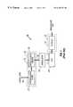
- a DAC system 10includes a digital portion 19 and an analog portion 21 . If the DAC is an oversampling delta-sigma type, the digital portion will typically include an interpolator 13 .
- the interpolator 13includes an interpolation filter 23 and a sample-and-hold circuit 25 .
- the interpolation filter 23increases the sample rate and removes or significantly attenuates energy at f s /2 and above, where f s is the input sampling frequency.
- the output of the interpolation filter 23is processed through the sample-and-hold circuit 25 to provide an over-sampled output.
- the output of the sample-and-hold circuit 25is sent to modulator 15 which converts the oversampled signal into a one-bit data stream.
- the modulator 15may be a delta-sigma modulator which provides good low level performance and can act as a one-bit digital quantizer.
- the one-bit data streamis sent to a one-bit DAC 29 .
- the signal from the one-bit DAC 29is then fed to the analog portion 21 .
- the analog portion 21includes at least a filter 17 .
- the filter 17may be an analog low pass filter such as a switched capacitor filter.
- a typical rate at which data may stream through the DAC system 10may be 48 kHz. If this data is then passed to a downstream circuit which operates at a different speed, such as a constrained pipe, the data will either back up (if the downstream circuit operates at a lower speed), or stall (if the downstream circuit operates at a higher speed). For example, data may be recorded at 48 kHz and subsequently stored. The data may then be streamed to a system through a constrained pipe at an average rate of 46 kHz. The output will periodically stall because the data rate through the constrained pipe cannot be increased.
- a multistream systemmay include a plurality of such streams.
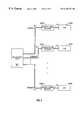
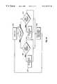
- FIG. 2shows one embodiment of such a multistream system.
- a plurality of DACs 10 A- 10 Nmay be employed, each attending to and servicing a stream A-N of an input multistream XX of data.
- the present inventionaddresses the above problems on a stream-by-stream basis by dynamically compensating for differences in data rates.
- the status of an input buffer of a streamis monitored and used to change the number of oversamples within a frame.
- the input buffer of a streamis still monitored but a high frequency clock in the system is used to stall the codec for one clock. In both embodiments, distortion due to differences in data rates is reduced.
- the methodincludes steps of receiving samples of a signal of a stream at a sampling rate, oversampling the sampled signal to generate a prespecified number of oversamples per a frame, and deleting or repeating one or more of the oversamples per frame to remove the overflow or underflow condition.
- the methodincludes receiving samples of a signal of a stream at a sampling rate and oversampling the sampled signal to generate one of a prespecified number of oversamples per a frame.
- the prespecified numberis equal to a nominal number in the absence of an overflow or underflow condition, the prespecified number is greater than the nominal number in an underflow condition, and the prespecified number is less than the nominal number in an overflow condition.
- the methodincludes steps of receiving samples of a signal of a stream at a sampling rate, oversampling the sampled signal to generate a prespecified number of oversamples per a frame; and stalling the circuit for a number of cycles of the master clock to remove the overflow or underflow condition.
- FIG. 1is a schematic block diagram of a prior art DAC system.
- FIG. 2is a schematic block diagram of a prior art multistreamed DAC system.
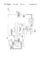
- FIG. 3is a schematic block diagram of a multistreamed DAC system according to an embodiment of the present invention.
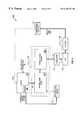
- FIG. 4is a schematic block diagram of a multistreamed DAC system according to another embodiment of the present invention.
- FIG. 5is a schematic block diagram of a DAC system according to an embodiment of the present invention showing control of an input buffer for a single stream of data.
- FIG. 6is a schematic block diagram of a DAC system according to an embodiment of the present invention showing control of an input buffer via a variable interpolation filter for a single stream of data.
- FIG. 7is a schematic block diagram of a DAC system according to an embodiment of the present invention showing control of an input buffer via an interpolation filter and a frame controller for a single stream of data.
- FIG. 8is a schematic block diagram of a DAC system according to an embodiment of the present invention showing control of a stall condition by using a master clock to stall the code for a clock cycle for a single stream of data.
- FIG. 9is a flowchart for an adaptive control loop according to an embodiment of the present invention for a single stream of data.
- FIG. 10shows a flowchart for the detection of an appropriate peak frame in a single stream of data for use in inserting or removing oversamples at random rates.
- FIG. 3shows a schematic block diagram of the invention.
- a multistream input 501includes N data streams labeled A-N. Each data stream A-N is incident, in the digital regime, on a variable frame adjuster 503 A- 503 N. The adjusted data streams are each incident on a DAC 505 A- 505 N.
- the nature of the variable frame adjusters 503 A- 503 N and DACs 505 A- 505 Nis discussed in more detail below.
- a variable frame adjuster and a DACare combined in a unitary circuit.
- the streams from each variable frame adjusterare mixed in a mixer 507 .
- a single streamis emitted from mixer 507 , which is then sent to a DAC 509 for conversion.
- the mixer 507may operate synchronously with a clock of its own, operating on all streams as though their data were “pull” type data. It may also be noted in this embodiment that the multistream mixing may result in less underflow conditions, due to the presence of many streams being mixed.
- variable frame adjustersmay operate on streams.
- FIG. 5shows such a variable frame adjuster in the context of a DAC system 110 .
- the variable frame adjusteris included in the interpolation filter 123 .
- digital dataflows to an input buffer 111 in digital portion 119 .
- the digital portion 119includes an interpolator 113 having an interpolation filter 123 and a sample-and-hold circuit 125 .
- the dataflows to a modulator 115 and a one-bit DAC 129 .
- the analog datais coupled to the analog portion 121 which includes a filter 117 .
- the analog datathen may flow out of the DAC system 110 and into downstream circuitry 131 .
- the contents of the input buffer 111may be tested in a monitor 133 .
- the monitor 133may check for underflow, overflow, near underflow, or near overflow conditions. The results of the testing may be used to control various parts of the DAC system 110 , or various parts of a circuit in which the DAC system 110 is located, in accordance with the principles of the invention.
- the status of the contents of the input buffer 111 as tested by monitor 133can be used to make adjustments to other parts of the system in order to accommodate differing data rates. The way in which such adjustments are made are presented below as example embodiments of the invention.
- the status of the input buffer 111can indicate whether the downstream rate is greater than or less than the upstream rate. For example, if the input buffer 111 is full or nearly full, the downstream rate is likely to be less than the upstream rate. In other words, the data rate is too high to be accommodated by all downstream circuitry beginning at the digital portion 119 . If the input buffer 111 is empty or nearly so, the downstream rate is likely greater than the upstream rate. In general, it is preferable to allow the input buffer 111 to operate without running empty.
- Management of the input buffer 111may include lengthening or shortening the sample frames to accommodate the different data rates.
- the codec frame lengthis varied.
- the number of oversamples within the frameis varied.
- the inventionwill be described in the context of a DAC system. However, one skilled in the art will recognize other systems in which the invention may be employed.
- the inventionmay be employed in the context of an ADC or other devices in which both push-data and pull-data are present, such as a television tuner card in a computer.
- the tolerance of a standard crystal oscillator in a systemleads to differences in data rates.
- This on-demand datamay be from any type of storage medium that provides a feedback path for control. Examples of this type include HDD, CD, DVD, PC memory systems, and many others.
- a DAC 210 in FIG. 6One way of constructing this embodiment is shown by a DAC 210 in FIG. 6 .
- This embodimentinvolves the use of a variable interpolation filter 145 .
- the interpolation filteris in part responsible for increasing or decreasing the sample rate.
- the variable interpolation filter 145can generate extra or fewer oversamples for the given frame. In most cases, one extra or one fewer would be appropriate. By performing this in accordance with the oversampling rate, the distortion is reduced as compared with performing this at the original sample rate before the interpolation filter.
- the digital portion 119affects the input buffer 111 by way of data overflowing in the input buffer 111 or by the input buffer 111 running empty. In other words, the digital portion affects the input buffer 111 by overflowing or stalling. In a different embodiment, the digital portion 119 may actually provide a signal to input buffer 111 or to a monitor 133 within the input buffer 111 . This signal would then provide an indication of the state of the data rate in the downstream circuitry 131 or even downstream of the downstream circuitry 131 .
- the input buffernever completely overflows or stalls.
- the monitordetects when these conditions are more likely to occur and signals the digital portion 119 to alter its number of oversamples per frame.
- the monitorin this fashion, provides signals identifying a “near overflow” or a “near stall” condition or a rate of change indicating that such is likely to occur.
- variable interpolation filter 145Once a signal is received indicating that a near stall or overflow condition has occurred, the signal is sent to a controller 137 within the variable interpolation filter 145 . This signal may be sent from the monitor 133 within buffer 111 . Once received, the signal causes the variable interpolation filter 145 to alter the number of oversamples per frame. In other words, rather than having the interpolation filter provide a uniform number of additional oversamples per input sample, the variable interpolation filter 145 inserts or deletes oversamples as required to avoid the stall or overflow condition described above.
- variable interpolation filter 145usually inserts 128 oversamples per each input sample, a near overflow condition may cause the variable interpolation filter to insert only 127 .
- a near stall conditionmay cause the variable interpolation filter to insert 129 .
- An appropriate number of coefficientsis chosen for the extra or fewer oversamples. Appropriate control over the number of oversamples created is provided by the controller 137 . In other words, in the example above, instead of 128 coefficients being chosen, 127 or 129 coefficients would be chosen.
- the interpolation filtermay generate a fixed number of oversamples per input sample. However, once oversampling is completed, a particular oversample may be deleted or repeated in order to switch to a 127/129 oversample frame if required by a near overflow or near stall condition.
- a DAC 310has an interpolation filter 143 with two stages: an 102 oversampling portion 139 and a frame controller 141 .
- the oversampling portion 139provides the requisite number of oversamples per sample, e.g., 128.
- the frame controller 141deletes or repeats an oversample according to the stall or overflow condition.
- the determination of when the frame controller 141 is required to edit the number of oversamplesmay be made by the input buffer monitor 133 or by some other source, and is carried out via a controller 147 .
- the controller 147 and the frame controller 141may be within the same or different blocks of the circuit.
- the location within the frame of the oversample that is deleted or insertedmay be chosen in a random manner to avoid the generation of unwanted tonal components. Such a method is described below. If tonal component generation is not a factor, the location of the oversample chosen may be arbitrary. For example, the first oversample or the last oversample may always be the oversample chosen.
- any error introduced by the removal or addition of oversamplesis spread over all (approximately) 128 oversamples. In other words, errors occur to oversampled values rather than to raw input samples so as to preserve data integrity.
- FIG. 8shows a master clock 151 controlling the interpolation filter 149 .
- the master clock 151may, of course, also control various other aspects of the system.
- the master clock 151may be used to create other clocks whose rates are either the same or are based on the master clock 151 . The presence and rates of these other clocks depend on the requirements of the system.
- the clock with the highest ratehere denoted MCLK 151 , may be used as the basis for the stall procedure.
- the MCLK 151may be caused to stall for one or more clock cycles or alternatively for one or more phases of the MCLK 151 .
- the downstream circuitry 131may be allowed time to process the overflow oversamples and thus remove the overflow condition.
- the resulting frames in the codecwould be slipped.
- This embodimentmay produce less distortion than the sampling based embodiments above.
- Using a half-clock stallleads to:
- the clock stallthus provides 60 dB less distortion than the sample-based solutions because the master clock has a much higher resolution than the sample rate. It should be noted in this embodiment that the bus interface would need to operate asynchronously such that the bus would not see the stall of the MCLK 151 .
- the monitor 133 of input buffer 111may be used to detect and correct overflows or underflows in several ways. For example, low and high thresholds may be set and used to trigger the change in the frame length as described above. The resulting change in data consumption rate causes the input buffer 111 to move back between the low and high thresholds and the oversamples per frame are reset to nominal. If the tested parameter is not reset (due, e.g., to a large mismatch in data rates) the frame length may be adjusted further to increase the rate of recovery.
- monitor 133may consider the number of oversamples per frame to be a variable which is usually at a steady-state value but which varies with overflows and underflows.
- this methodtermed herein the “loop offset mode”
- thresholdsare still set at low and high points but the number of oversamples per frame no longer tends towards a fixed value. Rather, the number of oversamples per frame tends towards whatever value is required to reduce the overflow or underflow.
- the number of oversamples per framemay increase to 129 from 128). This reduced the underflow to be eliminated. Rather than move back to 128, the number of oversamples per frame stays at 129 until the buffer falls below the low threshold again or above the high threshold.
- the loop offset modemay be especially useful when the sourcing rate is significantly different from the playback rate.
- the codec internal frameshould be fully independent of the audio input frame.
- FIG. 9shows a flowchart for an adaptive control loop used in the codec input buffer for a single stream of data, and in particular an operation of an adaptive error concealment codec. Thresholds are established for both overflow and underflow conditions for each stream in the multistreamed data.
- the first step in each streamis subsystem initialization 201 .
- a decision 203is then made as to whether the adaptive circuit is enabled. This decision ensures that the codec has a mode that is compatible with industry codecs. If the adaptive circuit is enabled, then a determination is made as to whether the “loop offset mode” is enabled (step 205 ).
- the loop offset modeis particularly suitable when rates vary significantly in different portions of a system because the frame size may continue to be modified in a rate-adaptive manner.
- step 207the determination of overflow (step 207 ) or underflow occurs (step 209 ). For example, if the input buffer falls below the low threshold (underflow step 209 ), each consecutive frame in which the buffer is below the low threshold has a frame length that is increased (step 211 ), e.g., by one oversample value. Once the playback rate matches the source rate, the buffer status moves back above the low threshold and stabilizes at a frame size appropriate for the incoming data. If an overflow condition occurred, each consecutive frame in which the buffer is above the high threshold has a frame length that is decreased (step 213 ), e.g., by one oversample value.
- a test for an empty buffermay occur.
- the frame sizeis adjusted to compensate and the final size of the frame is calculated (step 219 ) from the loop responses. The net effect is that the data is played at a rate that is different from its recorded rate; however, empty frames do not occur, nor do overflows.
- the frame lengthis reset, for each frame, to the preset value (e.g., 128 oversamples per frame) (step 217 ). For small drifts between the source data and the playback, this way may be preferred and allows for instantaneous correction with low distortion. It should be noted that this flowchart is only representative of one of the several methods available.
- the timing in which the interpolator may be caused to insert or remove an oversamplemay be adjusted.
- the interpolatormay simply insert or remove the oversample accordingly; however, this may lead to the tonal generation above. Instead, the interpolator may choose to wait to insert or remove the oversample until a prespecified time.
- the appropriate prespecified time to insert or remove an oversamplemay be when the frame's oversamples have an extremal value (i.e., a maximum or minimum at approximately zero slope). At these points, addition or removal of oversamples does not result in a significant change in the frequency components. A certain time period is added but little distortion is added.
- FIG. 10shows an extremal detection flowchart.
- an extremal flagis reset (step 301 ).
- the first testmay be for a negative slope of the current frame (step 303 ). If the slope is negative, then the following frame slope is tested (step 305 ). If this slope is not negative, then the extremal flag is set (step 307 ) and the insertion or removal may proceed. If this slope is negative, other sample processing may occur (step 309 ) and the slope detect procedure is begun again. If the current frame slope is not negative, then the following frame slope is tested (step 311 ). If this slope is negative, then the extremal flag is set (step 313 ) and the insertion or removal may proceed. If this slope is not negative, other sample processing may occur (step 309 ) and the slope detect procedure is begun again. Again, it is noted that this flowchart is only representative of one of the several methods available.
- the interpolatormay be forced to insert or remove the oversample despite the lack of an extremal frame (e.g., a 20 Hz input with extremes every 25 ms).
- an extremal framee.g., a 20 Hz input with extremes every 25 ms.
- the source data frame sync and the internal codec frame syncdo not need to sync-up because each incoming stream is destined for the analog domain.
- each incoming streamis destined for the analog domain.
- the datais in continuous time, allowing full decoupling of the data bus frame sync from the internal codec frame sync.
- the accumulated errorwhen an extra audio oversample is created (to account for data rate disparities in a system), may be estimated as follows.
Landscapes
- Engineering & Computer Science (AREA)
- Multimedia (AREA)
- Signal Processing (AREA)
- Signal Processing For Digital Recording And Reproducing (AREA)
Abstract
Description
Claims (25)
Priority Applications (3)
| Application Number | Priority Date | Filing Date | Title |
|---|---|---|---|
| US09/111,918US6169747B1 (en) | 1998-07-08 | 1998-07-08 | Variable code frame length for multistream applications |
| AU50930/99AAU5093099A (en) | 1998-07-08 | 1999-07-08 | Variable codec frame length for multistream applications |
| PCT/US1999/015408WO2000003510A1 (en) | 1998-07-08 | 1999-07-08 | Variable codec frame length for multistream applications |
Applications Claiming Priority (1)
| Application Number | Priority Date | Filing Date | Title |
|---|---|---|---|
| US09/111,918US6169747B1 (en) | 1998-07-08 | 1998-07-08 | Variable code frame length for multistream applications |
Publications (1)
| Publication Number | Publication Date |
|---|---|
| US6169747B1true US6169747B1 (en) | 2001-01-02 |
Family
ID=22341133
Family Applications (1)
| Application Number | Title | Priority Date | Filing Date |
|---|---|---|---|
| US09/111,918Expired - Fee RelatedUS6169747B1 (en) | 1998-07-08 | 1998-07-08 | Variable code frame length for multistream applications |
Country Status (3)
| Country | Link |
|---|---|
| US (1) | US6169747B1 (en) |
| AU (1) | AU5093099A (en) |
| WO (1) | WO2000003510A1 (en) |
Cited By (22)
| Publication number | Priority date | Publication date | Assignee | Title |
|---|---|---|---|---|
| US20010033583A1 (en)* | 1999-04-13 | 2001-10-25 | Rabenko Theodore F. | Voice gateway with downstream voice synchronization |
| US20020061012A1 (en)* | 1999-04-13 | 2002-05-23 | Thi James C. | Cable modem with voice processing capability |
| WO2002095949A1 (en)* | 2001-05-24 | 2002-11-28 | Cirrus Logic, Incorporated | Apparatus and method for multi-channel digital to analog conversion of signals with different sample rates |
| US20030005138A1 (en)* | 2001-06-25 | 2003-01-02 | Giffin Michael Shawn | Wireless streaming audio system |
| EP1316955A1 (en)* | 2001-11-30 | 2003-06-04 | Infineon Technologies AG | Intermediate storage device |
| US6665728B1 (en)* | 1998-12-30 | 2003-12-16 | Intel Corporation | Establishing optimal latency in streaming data applications that use data packets |
| US20040068482A1 (en)* | 2000-11-29 | 2004-04-08 | Hideki Yoshida | Data processor |
| US20040174875A1 (en)* | 1999-06-10 | 2004-09-09 | Geagan John B. | Method for real time protocol media recording |
| US20050031097A1 (en)* | 1999-04-13 | 2005-02-10 | Broadcom Corporation | Gateway with voice |
| US20050073453A1 (en)* | 2003-10-01 | 2005-04-07 | Eric Cheng | System of multi-channel shared resistor-string digital-to-analog converters and method of the same |
| US6888840B1 (en)* | 1998-10-02 | 2005-05-03 | Thomson Licensing S.A. | Output symbol rate control in a packet transport rate conversion system |
| US20050105464A1 (en)* | 2003-11-17 | 2005-05-19 | International Business Machines Corporation | Differentiated handling of SIP messages for VoIP call control |
| US6917321B1 (en) | 2000-05-21 | 2005-07-12 | Analog Devices, Inc. | Method and apparatus for use in switched capacitor systems |
| US6952399B1 (en)* | 2000-10-12 | 2005-10-04 | Sprint Communications Company L.P. | Method and apparatus for synchronizing the coding and decoding of information in an integrated services hub |
| US20050223041A1 (en)* | 2000-08-31 | 2005-10-06 | Sony Corporation | Server reservation method, reservation control appartus and program storage medium |
| US7199740B1 (en) | 2000-05-21 | 2007-04-03 | Analog Devices, Inc. | Method and apparatus for use in switched capacitor systems |
| US20100023142A1 (en)* | 2008-07-24 | 2010-01-28 | Qualcomm Incorporated | Method and apparatus for transmit and receive clock mismatch compensation |
| US20100146145A1 (en)* | 2008-12-04 | 2010-06-10 | Swarmcast, Inc. | Adaptive playback rate with look-ahead |
| US20100191525A1 (en)* | 1999-04-13 | 2010-07-29 | Broadcom Corporation | Gateway With Voice |
| US20100306373A1 (en)* | 2009-06-01 | 2010-12-02 | Swarmcast, Inc. | Data retrieval based on bandwidth cost and delay |
| CN104994426A (en)* | 2014-07-07 | 2015-10-21 | Tcl集团股份有限公司 | Method and system of program video recognition |
| US20180367151A1 (en)* | 2017-06-15 | 2018-12-20 | Cirrus Logic International Semiconductor Ltd. | Asynchronous positional feedback for asynchronous and isochronous communication |
Families Citing this family (1)
| Publication number | Priority date | Publication date | Assignee | Title |
|---|---|---|---|---|
| JP4722266B2 (en)* | 2000-08-16 | 2011-07-13 | 富士通セミコンダクター株式会社 | Oversampling FIR filter, oversampling FIR filter control method, semiconductor integrated circuit having oversampling FIR filter, and communication system for transmitting data filtered by oversampling FIR filter |
Citations (10)
| Publication number | Priority date | Publication date | Assignee | Title |
|---|---|---|---|---|
| US5159447A (en)* | 1991-05-23 | 1992-10-27 | At&T Bell Laboratories | Buffer control for variable bit-rate channel |
| US5235618A (en)* | 1989-11-06 | 1993-08-10 | Fujitsu Limited | Video signal coding apparatus, coding method used in the video signal coding apparatus and video signal coding transmission system having the video signal coding apparatus |
| US5398072A (en) | 1993-10-25 | 1995-03-14 | Lsi Logic Corporation | Management of channel buffer in video decoders |
| US5453790A (en)* | 1992-03-27 | 1995-09-26 | Alcatel N.V. | Video decoder having asynchronous operation with respect to a video display |
| US5565924A (en)* | 1995-01-19 | 1996-10-15 | Lucent Technologies Inc. | Encoder/decoder buffer control for variable bit-rate channel |
| US5619341A (en)* | 1995-02-23 | 1997-04-08 | Motorola, Inc. | Method and apparatus for preventing overflow and underflow of an encoder buffer in a video compression system |
| US5663962A (en) | 1994-09-29 | 1997-09-02 | Cselt- Centro Studi E Laboratori Telecomunicazioni S.P.A. | Method of multiplexing streams of audio-visual signals coded according to standard MPEG1 |
| US5905732A (en) | 1996-08-27 | 1999-05-18 | Zenith Electronics Corporation | PCR restamper |
| US5914960A (en)* | 1996-01-26 | 1999-06-22 | Nokia Telecommunications Oy | Method to accomplish a packet-form connection |
| US5966385A (en)* | 1995-03-29 | 1999-10-12 | Hitachi, Ltd. | Decoder for compressed and multiplexed video and audio data |
- 1998
- 1998-07-08USUS09/111,918patent/US6169747B1/ennot_activeExpired - Fee Related
- 1999
- 1999-07-08AUAU50930/99Apatent/AU5093099A/ennot_activeAbandoned
- 1999-07-08WOPCT/US1999/015408patent/WO2000003510A1/enactiveApplication Filing
Patent Citations (10)
| Publication number | Priority date | Publication date | Assignee | Title |
|---|---|---|---|---|
| US5235618A (en)* | 1989-11-06 | 1993-08-10 | Fujitsu Limited | Video signal coding apparatus, coding method used in the video signal coding apparatus and video signal coding transmission system having the video signal coding apparatus |
| US5159447A (en)* | 1991-05-23 | 1992-10-27 | At&T Bell Laboratories | Buffer control for variable bit-rate channel |
| US5453790A (en)* | 1992-03-27 | 1995-09-26 | Alcatel N.V. | Video decoder having asynchronous operation with respect to a video display |
| US5398072A (en) | 1993-10-25 | 1995-03-14 | Lsi Logic Corporation | Management of channel buffer in video decoders |
| US5663962A (en) | 1994-09-29 | 1997-09-02 | Cselt- Centro Studi E Laboratori Telecomunicazioni S.P.A. | Method of multiplexing streams of audio-visual signals coded according to standard MPEG1 |
| US5565924A (en)* | 1995-01-19 | 1996-10-15 | Lucent Technologies Inc. | Encoder/decoder buffer control for variable bit-rate channel |
| US5619341A (en)* | 1995-02-23 | 1997-04-08 | Motorola, Inc. | Method and apparatus for preventing overflow and underflow of an encoder buffer in a video compression system |
| US5966385A (en)* | 1995-03-29 | 1999-10-12 | Hitachi, Ltd. | Decoder for compressed and multiplexed video and audio data |
| US5914960A (en)* | 1996-01-26 | 1999-06-22 | Nokia Telecommunications Oy | Method to accomplish a packet-form connection |
| US5905732A (en) | 1996-08-27 | 1999-05-18 | Zenith Electronics Corporation | PCR restamper |
Cited By (50)
| Publication number | Priority date | Publication date | Assignee | Title |
|---|---|---|---|---|
| US6888840B1 (en)* | 1998-10-02 | 2005-05-03 | Thomson Licensing S.A. | Output symbol rate control in a packet transport rate conversion system |
| US6665728B1 (en)* | 1998-12-30 | 2003-12-16 | Intel Corporation | Establishing optimal latency in streaming data applications that use data packets |
| US8005976B2 (en) | 1998-12-30 | 2011-08-23 | Intel Corporation | Establishing optimal latency in streaming data applications that use data packets |
| US20090262749A1 (en)* | 1998-12-30 | 2009-10-22 | Graumann David L | Establishing optimal latency in streaming data applications that use data packets |
| US7552229B2 (en) | 1998-12-30 | 2009-06-23 | Intel Corporation | Establishing optimal latency in streaming data applications that use data packets |
| US20050031097A1 (en)* | 1999-04-13 | 2005-02-10 | Broadcom Corporation | Gateway with voice |
| US20100191525A1 (en)* | 1999-04-13 | 2010-07-29 | Broadcom Corporation | Gateway With Voice |
| USRE46142E1 (en) | 1999-04-13 | 2016-09-06 | Broadcom Corporation | Modem with voice processing capability |
| US9288334B2 (en) | 1999-04-13 | 2016-03-15 | Broadcom Corporation | Modem with voice processing capability |
| US8582577B2 (en) | 1999-04-13 | 2013-11-12 | Broadcom Corporation | Modem with voice processing capability |
| US7023868B2 (en)* | 1999-04-13 | 2006-04-04 | Broadcom Corporation | Voice gateway with downstream voice synchronization |
| US20010033583A1 (en)* | 1999-04-13 | 2001-10-25 | Rabenko Theodore F. | Voice gateway with downstream voice synchronization |
| US8254404B2 (en)* | 1999-04-13 | 2012-08-28 | Broadcom Corporation | Gateway with voice |
| US20020061012A1 (en)* | 1999-04-13 | 2002-05-23 | Thi James C. | Cable modem with voice processing capability |
| US7933295B2 (en)* | 1999-04-13 | 2011-04-26 | Broadcom Corporation | Cable modem with voice processing capability |
| US7701954B2 (en)* | 1999-04-13 | 2010-04-20 | Broadcom Corporation | Gateway with voice |
| US7447242B2 (en)* | 1999-06-10 | 2008-11-04 | Blue Coat Systems, Inc. | Method for real time protocol media recording |
| US20040174875A1 (en)* | 1999-06-10 | 2004-09-09 | Geagan John B. | Method for real time protocol media recording |
| US6917321B1 (en) | 2000-05-21 | 2005-07-12 | Analog Devices, Inc. | Method and apparatus for use in switched capacitor systems |
| US7199740B1 (en) | 2000-05-21 | 2007-04-03 | Analog Devices, Inc. | Method and apparatus for use in switched capacitor systems |
| US7856468B2 (en) | 2000-08-31 | 2010-12-21 | Sony Corporation | Server reservation method, reservation control apparatus and program storage medium |
| US20050223041A1 (en)* | 2000-08-31 | 2005-10-06 | Sony Corporation | Server reservation method, reservation control appartus and program storage medium |
| US6952399B1 (en)* | 2000-10-12 | 2005-10-04 | Sprint Communications Company L.P. | Method and apparatus for synchronizing the coding and decoding of information in an integrated services hub |
| US20040068482A1 (en)* | 2000-11-29 | 2004-04-08 | Hideki Yoshida | Data processor |
| US7389318B2 (en)* | 2000-11-29 | 2008-06-17 | Sony Corporation | Data processor capable of preventing data overflows and underflows |
| WO2002095949A1 (en)* | 2001-05-24 | 2002-11-28 | Cirrus Logic, Incorporated | Apparatus and method for multi-channel digital to analog conversion of signals with different sample rates |
| US6531975B1 (en)* | 2001-05-24 | 2003-03-11 | Cirrus Logic, Incorporated | Apparatus and method for multi-channel digital to analog conversion of signals with different sample rates |
| EP1407552A4 (en)* | 2001-05-24 | 2004-08-18 | Cirrus Logic Inc | Apparatus and method for multi-channel digital to analog conversion of signals with different sample rates |
| US20030005138A1 (en)* | 2001-06-25 | 2003-01-02 | Giffin Michael Shawn | Wireless streaming audio system |
| US6891762B2 (en) | 2001-11-30 | 2005-05-10 | Infineon Technologies Ag | Buffer memory device |
| EP1316955A1 (en)* | 2001-11-30 | 2003-06-04 | Infineon Technologies AG | Intermediate storage device |
| US20030137880A1 (en)* | 2001-11-30 | 2003-07-24 | Jens Barrenscheen | Buffer memory device |
| US20050073453A1 (en)* | 2003-10-01 | 2005-04-07 | Eric Cheng | System of multi-channel shared resistor-string digital-to-analog converters and method of the same |
| US20050105464A1 (en)* | 2003-11-17 | 2005-05-19 | International Business Machines Corporation | Differentiated handling of SIP messages for VoIP call control |
| US7701854B2 (en)* | 2003-11-17 | 2010-04-20 | International Business Machines Corporation | Differentiated handling of SIP messages for VoIP call control |
| US20100023142A1 (en)* | 2008-07-24 | 2010-01-28 | Qualcomm Incorporated | Method and apparatus for transmit and receive clock mismatch compensation |
| CN102100022B (en)* | 2008-07-24 | 2014-03-19 | 高通股份有限公司 | Method and apparatus for transmitting and receiving clock mismatch compensation |
| US8527075B2 (en)* | 2008-07-24 | 2013-09-03 | Qualcomm Incorporated | Method and apparatus for transmit and receive clock mismatch compensation |
| US8375140B2 (en)* | 2008-12-04 | 2013-02-12 | Google Inc. | Adaptive playback rate with look-ahead |
| US20130132525A1 (en)* | 2008-12-04 | 2013-05-23 | Google Inc. | Adaptive playback with look-ahead |
| US9112938B2 (en)* | 2008-12-04 | 2015-08-18 | Google Inc. | Adaptive playback with look-ahead |
| US20100146145A1 (en)* | 2008-12-04 | 2010-06-10 | Swarmcast, Inc. | Adaptive playback rate with look-ahead |
| US20100306373A1 (en)* | 2009-06-01 | 2010-12-02 | Swarmcast, Inc. | Data retrieval based on bandwidth cost and delay |
| US9948708B2 (en) | 2009-06-01 | 2018-04-17 | Google Llc | Data retrieval based on bandwidth cost and delay |
| CN104994426A (en)* | 2014-07-07 | 2015-10-21 | Tcl集团股份有限公司 | Method and system of program video recognition |
| US20160007058A1 (en)* | 2014-07-07 | 2016-01-07 | TCL Research America Inc. | System and method for video program recognition |
| US9432702B2 (en)* | 2014-07-07 | 2016-08-30 | TCL Research America Inc. | System and method for video program recognition |
| CN104994426B (en)* | 2014-07-07 | 2020-07-21 | Tcl科技集团股份有限公司 | Program video identification method and system |
| US20180367151A1 (en)* | 2017-06-15 | 2018-12-20 | Cirrus Logic International Semiconductor Ltd. | Asynchronous positional feedback for asynchronous and isochronous communication |
| US10651860B2 (en)* | 2017-06-15 | 2020-05-12 | Cirrus Logic, Inc. | Asynchronous positional feedback for asynchronous and isochronous communication |
Also Published As
| Publication number | Publication date |
|---|---|
| AU5093099A (en) | 2000-02-01 |
| WO2000003510A1 (en) | 2000-01-20 |
Similar Documents
| Publication | Publication Date | Title |
|---|---|---|
| US6169747B1 (en) | Variable code frame length for multistream applications | |
| US6678243B2 (en) | Variable codec frame length | |
| US7630612B2 (en) | Video stream adaptive frame rate scheme | |
| US20060092918A1 (en) | Audio receiver having adaptive buffer delay | |
| JP2007501428A (en) | Buffer management system, digital audio receiver, headphones, speaker, buffer management method | |
| WO2001035674A1 (en) | Adaptive control of streaming data in a graph | |
| US7439885B2 (en) | Method and system for sample rate conversion | |
| WO2007013044A1 (en) | Data stream synchronization | |
| JPH04299653A (en) | Clock reproducing circuit | |
| US6735223B1 (en) | Method of controlling offset of time stamp and apparatus for transmitting packet using the same | |
| JP2004282692A (en) | Network telephone set and voice decoding apparatus | |
| JP4425115B2 (en) | Clock synchronization apparatus and program | |
| CN114513711B (en) | Optical fiber Ethernet interface communication method, FPGA module and system | |
| JP4476034B2 (en) | Receiver | |
| US7054400B2 (en) | Digital AV signal processing apparatus | |
| US20090190702A1 (en) | Digital timing correction system, method and apparatus | |
| JP4553897B2 (en) | Asynchronous jitter reduction technique | |
| JP4642749B2 (en) | Oversampling method to reduce jitter | |
| JP5001318B2 (en) | Digital audio signal transmission apparatus and digital audio signal transmission method | |
| JP2007104569A (en) | Data receiver | |
| US8009783B2 (en) | Synchronous digital data transmission interface | |
| GB2331678A (en) | Controlling data flow in a synchronous data compression system | |
| JPH11234634A (en) | Data transmitter and data multiplexer | |
| JP3901162B2 (en) | Timing adjustment apparatus and method | |
| JPH10501941A (en) | Synchronization of packetized digital data stream to output processor in television signal processing system |
Legal Events
| Date | Code | Title | Description |
|---|---|---|---|
| AS | Assignment | Owner name:ESS TECHNOLOGY, INC., TEXAS Free format text:ASSIGNMENT OF ASSIGNORS INTEREST;ASSIGNORS:SARTAIN, DARYL;SCULLEY, TERRY;REEL/FRAME:009307/0473 Effective date:19980707 | |
| FPAY | Fee payment | Year of fee payment:4 | |
| FEPP | Fee payment procedure | Free format text:PAYER NUMBER DE-ASSIGNED (ORIGINAL EVENT CODE: RMPN); ENTITY STATUS OF PATENT OWNER: LARGE ENTITY Free format text:PAYOR NUMBER ASSIGNED (ORIGINAL EVENT CODE: ASPN); ENTITY STATUS OF PATENT OWNER: LARGE ENTITY | |
| FEPP | Fee payment procedure | Free format text:PAYER NUMBER DE-ASSIGNED (ORIGINAL EVENT CODE: RMPN); ENTITY STATUS OF PATENT OWNER: LARGE ENTITY Free format text:PAYOR NUMBER ASSIGNED (ORIGINAL EVENT CODE: ASPN); ENTITY STATUS OF PATENT OWNER: LARGE ENTITY | |
| AS | Assignment | Owner name:THE PRIVATE BANK OF THE PENINSULA, CALIFORNIA Free format text:SECURITY AGREEMENT;ASSIGNOR:ESS TECHNOLOGY, INC.;REEL/FRAME:021212/0413 Effective date:20080703 Owner name:THE PRIVATE BANK OF THE PENINSULA,CALIFORNIA Free format text:SECURITY AGREEMENT;ASSIGNOR:ESS TECHNOLOGY, INC.;REEL/FRAME:021212/0413 Effective date:20080703 | |
| REMI | Maintenance fee reminder mailed | ||
| FPAY | Fee payment | Year of fee payment:8 | |
| SULP | Surcharge for late payment | Year of fee payment:7 | |
| REMI | Maintenance fee reminder mailed | ||
| LAPS | Lapse for failure to pay maintenance fees | ||
| STCH | Information on status: patent discontinuation | Free format text:PATENT EXPIRED DUE TO NONPAYMENT OF MAINTENANCE FEES UNDER 37 CFR 1.362 | |
| FP | Lapsed due to failure to pay maintenance fee | Effective date:20130102 |