US6169524B1 - Multi-pattern antenna having frequency selective or polarization sensitive zones - Google Patents
Multi-pattern antenna having frequency selective or polarization sensitive zonesDownload PDFInfo
- Publication number
- US6169524B1 US6169524B1US09/232,899US23289999AUS6169524B1US 6169524 B1US6169524 B1US 6169524B1US 23289999 AUS23289999 AUS 23289999AUS 6169524 B1US6169524 B1US 6169524B1
- Authority
- US
- United States
- Prior art keywords
- signals
- zone
- antenna
- zones
- frequency
- Prior art date
- Legal status (The legal status is an assumption and is not a legal conclusion. Google has not performed a legal analysis and makes no representation as to the accuracy of the status listed.)
- Expired - Lifetime
Links
- 230000010287polarizationEffects0.000titleclaimsabstractdescription33
- 238000005286illuminationMethods0.000claimsabstractdescription28
- 239000000463materialSubstances0.000claimsdescription16
- 239000011358absorbing materialSubstances0.000claimsdescription4
- 238000000034methodMethods0.000description7
- 238000004544sputter depositionMethods0.000description4
- XAGFODPZIPBFFR-UHFFFAOYSA-NaluminiumChemical compound[Al]XAGFODPZIPBFFR-UHFFFAOYSA-N0.000description3
- 229910052782aluminiumInorganic materials0.000description3
- 238000004891communicationMethods0.000description3
- OKTJSMMVPCPJKN-UHFFFAOYSA-NCarbonChemical compound[C]OKTJSMMVPCPJKN-UHFFFAOYSA-N0.000description2
- 238000004458analytical methodMethods0.000description2
- 238000000151depositionMethods0.000description2
- 238000005530etchingMethods0.000description2
- 238000007740vapor depositionMethods0.000description2
- JOYRKODLDBILNP-UHFFFAOYSA-NEthyl urethaneChemical compoundCCOC(N)=OJOYRKODLDBILNP-UHFFFAOYSA-N0.000description1
- 229910052799carbonInorganic materials0.000description1
- 239000000919ceramicSubstances0.000description1
- 239000011248coating agentSubstances0.000description1
- 238000000576coating methodMethods0.000description1
- 239000002131composite materialSubstances0.000description1
- 230000003247decreasing effectEffects0.000description1
- 238000005516engineering processMethods0.000description1
- 239000000284extractSubstances0.000description1
- 239000006260foamSubstances0.000description1
- 229910002804graphiteInorganic materials0.000description1
- 239000010439graphiteSubstances0.000description1
- 238000004519manufacturing processMethods0.000description1
- 238000004377microelectronicMethods0.000description1
Images


Classifications
- H—ELECTRICITY
- H01—ELECTRIC ELEMENTS
- H01Q—ANTENNAS, i.e. RADIO AERIALS
- H01Q15/00—Devices for reflection, refraction, diffraction or polarisation of waves radiated from an antenna, e.g. quasi-optical devices
- H01Q15/0006—Devices acting selectively as reflecting surface, as diffracting or as refracting device, e.g. frequency filtering or angular spatial filtering devices
- H01Q15/0013—Devices acting selectively as reflecting surface, as diffracting or as refracting device, e.g. frequency filtering or angular spatial filtering devices said selective devices working as frequency-selective reflecting surfaces, e.g. FSS, dichroic plates, surfaces being partly transmissive and reflective
- H—ELECTRICITY
- H01—ELECTRIC ELEMENTS
- H01Q—ANTENNAS, i.e. RADIO AERIALS
- H01Q1/00—Details of, or arrangements associated with, antennas
- H01Q1/27—Adaptation for use in or on movable bodies
- H01Q1/28—Adaptation for use in or on aircraft, missiles, satellites, or balloons
- H01Q1/288—Satellite antennas
- H—ELECTRICITY
- H01—ELECTRIC ELEMENTS
- H01Q—ANTENNAS, i.e. RADIO AERIALS
- H01Q19/00—Combinations of primary active antenna elements and units with secondary devices, e.g. with quasi-optical devices, for giving the antenna a desired directional characteristic
- H01Q19/10—Combinations of primary active antenna elements and units with secondary devices, e.g. with quasi-optical devices, for giving the antenna a desired directional characteristic using reflecting surfaces
- H01Q19/18—Combinations of primary active antenna elements and units with secondary devices, e.g. with quasi-optical devices, for giving the antenna a desired directional characteristic using reflecting surfaces having two or more spaced reflecting surfaces
- H01Q19/19—Combinations of primary active antenna elements and units with secondary devices, e.g. with quasi-optical devices, for giving the antenna a desired directional characteristic using reflecting surfaces having two or more spaced reflecting surfaces comprising one main concave reflecting surface associated with an auxiliary reflecting surface
- H01Q19/195—Combinations of primary active antenna elements and units with secondary devices, e.g. with quasi-optical devices, for giving the antenna a desired directional characteristic using reflecting surfaces having two or more spaced reflecting surfaces comprising one main concave reflecting surface associated with an auxiliary reflecting surface wherein a reflecting surface acts also as a polarisation filter or a polarising device
- H—ELECTRICITY
- H01—ELECTRIC ELEMENTS
- H01Q—ANTENNAS, i.e. RADIO AERIALS
- H01Q25/00—Antennas or antenna systems providing at least two radiating patterns
- H01Q25/007—Antennas or antenna systems providing at least two radiating patterns using two or more primary active elements in the focal region of a focusing device
Definitions
- Reflector antennasare frequently used on spacecraft to provide multiple uplink and downlink communication links between the spacecraft and the ground.
- the downlinksoperate at one frequency, typically around 20 GHz, and the uplinks operate at a second higher frequency, typically around 30 or 44 GHz.
- an illumination sourceis configured to illuminate the reflector body with two RF signals, one having a frequency of 20 GHz and the other having a frequency of 30 GHz.
- the reflectoris typically fabricated of a composite or honeycombed material coated with a reflective material, typically aluminum, which is reflective to RF signals of all frequencies.
- the disadvantage with this systemis that it is difficult to provide antenna patterns having predetermined beamwidths at different frequencies from the typical reflector. The beamwidth of an antenna beam is inversely proportional to the size of the reflector and the frequency of illumination.
- the uplink antenna pattern at 30 GHzwould have a smaller beamwidth than the downlink antenna pattern at 20 GHz thereby covering a smaller coverage zone than the downlink antenna pattern.
- conventional reflector antennashave used specially designed feed horns configured to under illuminate the reflector at 30 GHz, the higher frequency, thereby generating an antenna pattern at 30 GHz having a wider beamwidth. This is inefficient and often difficult to do since feed horns are extremely sensitive to tolerance and bandwidth limitations.
- a reflector antennain accord with the invention, comprises a single concave reflector body having a plurality of zones with each zone configured as a frequency selective or polarization sensitive zone. The zones can be partially, completely or not overlapping.
- An illumination sourceis configured to illuminate the reflector body with a plurality of RF signals with each zone reflecting one or more of the RF signals.
- the reflector bodygenerates a plurality of antenna patterns from the reflected RF signals with the shape & beamwidth of the antenna patterns being determined by the shape and dimensions of each zone. The shape and dimensions of each zone is thus preselected to provide an antenna pattern having a desired shape and beamwidth.
- the reflector bodyhas two concentric zones comprised of an inner zone and an outer zone encompassing the inner zone.
- the two zonesare illuminated with the RF signals having frequencies of approximately 20 GHz and 30 GHz.
- the inner zoneis comprised of a material which is reflective to RF signals of all frequencies
- the outer zoneis comprised of a material which reflects RF signals of a 20 GHz frequency and passes RF signals having a frequency of 30 GHz.
- the 30 GHz signalis reflected only by the inner zone and is not reflected by the second zone.
- Antenna patternsare generated at 20 and 30 GHz from the 20 and 30 GHz reflected signals respectively with the size and shape of only the inner zone determining the shape and beamwidth of the 30 GHz antenna pattern and the shape and beamwidth of both zones determining the shape and beamwidth of the 20 GHz antenna pattern.
- the dimensions of the inner and first zoneare preselected to generate 20 and 30 GHz antenna patterns having approximately equal shapes and beamwidth.
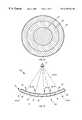
- FIG. 1 bis a side plane view of a reflector antenna having the reflector body shown in FIG. 1 a;
- FIG. 1 cshows antenna patterns generated by the reflector antenna shown in FIG. 1 b;
- FIG. 2 ais a top plane view of a reflector body in accordance with a second embodiment of the invention.
- FIG. 2 bis a side plane view of a reflector antenna having the reflector body shown in FIG. 2 a;
- FIG. 2 cshows antenna patterns generated by the reflector antenna shown in FIG. 2 b;
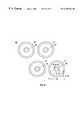
- FIG. 3 ais a top plane view of circular loop frequency selective elements in accordance with a third embodiment of the invention.
- FIGS. 3 b and 3 care top plane views of nested circular loop frequency selective elements in accordance with a fourth embodiment of the invention.
- FIG. 4 ais a top plane view of a reflector body in accordance with a fifth embodiment of the invention.
- FIG. 4 bis a side plane view of a reflector antenna having the reflector body shown in FIG. 4 a;
- FIGS. 4 c and 4 dshow the x and y axis principle plane antenna patterns respectively generated by the reflector antenna shown in FIG. 4 b.
- FIG. 5 ais a top plane view of a reflector body in accordance with a sixth embodiment of the invention.
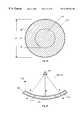
- FIG. 5 bis a side plane view of a reflector antenna having the reflector body shown in FIG. 5 a;
- FIG. 5 cshows antenna patterns generated by the reflector antenna shown in FIG. 5 b;
- FIG. 6 bis a side plane view of a reflector antenna having the reflector body shown in FIG. 6 a;
- FIG. 6 cshows antenna patterns generated by the reflector antenna shown in FIG. 6 b;
- FIG. 7 ais a side plane view of a reflector body in accordance with a eighth embodiment of the invention.
- FIG. 7 bis a side plane view of a reflector antenna having the reflector body shown in FIG. 7 a ;
- FIG. 7 cshows antenna patterns generated by the reflector antenna shown in FIG. 7 b.
- the reflector antenna 10for providing multiple antenna patterns 12 - 16 is illustrated.
- the reflector antenna 10can be configured as a prime focus feed reflector, an offset reflector, a cassegrain reflector or the like.
- the reflector antenna 10includes a reflector body 18 and an illumination source 20 .
- the reflector body 18is comprised of a plurality of zones 22 - 26 with each zone 22 - 26 configured to be a frequency selective or polarization sensitive zone.
- the illumination source 20is configured to illuminate the reflector body 18 with a plurality of RF signals depicted by the lines marked 28 - 32 with each RF signal 28 - 32 being of a preselected frequency or polarization.
- Each zone 22 - 26is configured to selectively reflect, pass or absorb selected RF signals 28 - 32 having preselected frequencies or polarizations.
- Antenna patterns 12 - 16are generated from each reflected RF signal 34 - 38 with the characteristics of each antenna pattern 12 - 16 , including the shape and beamwidth, being determined by the shape and dimensions of the zones 22 - 28 .
- the size and shape of each zone 22 - 28is preselected so that antenna patterns 12 - 16 are generated having desired shapes and beamwidths.
- a single reflector body 18By configuring a single reflector body 18 to comprise one or more frequency selective or polarization sensitive zones 22 - 26 , a plurality of antenna patterns 12 - 16 , each being of a preselected shape and beamwidth, can be generated from a single reflector antenna 10 .
- the reflector body 40is comprised of three concentric zones 42 - 46 .
- the first zone 42is configured to reflect RF signals having frequencies of f 1 -f 3 ;
- the second zone 44is configured to reflect RF signals having frequencies f 2 and f 3 and pass RF signals having a frequency of f 1 .
- the third zone 46is configured to reflect RF signals having frequencies of f 3 and pass RF signals having frequencies of f 1 and f 2 .
- the illumination source 48is configured to generate three RF signals depicted by the lines marked 50 - 54 where each RF signal 50 - 54 is of a different frequency f 1 -f 3 respectively.
- the first RF signal 50is incident on the reflector body 40 with the portion of the first RF signal 50 which is incident upon the first zone 42 being reflected by the first zone 42 .
- the portion of the first RF signal 50 which is incident on the second 44 and third 46 zonesis not reflected and pass through the second 44 and third 46 zones.
- only the first zone 42reflects the first RF signal 50 to provide a first reflected signal 56 which will form a first antenna pattern 58 having characteristics including shape and beamwidth which are substantially determined by the shape and dimensions of only the first zone 42 .
- the shape and dimensions of the first zone 42is thus preselected to provide a first antenna pattern 58 having predetermined pattern characteristics such as shape and beamwidth.
- the first zone 42is preferably formed of a light weight core 60 fabricated from a material such as Graphite, KevlarTM, NomexTM, aluminum honeycomb, or the like which are all commercially available materials with KevlarTM being fabricated by Hexcel Corporation located in Huntington Beach, Calif. and NomexTM being fabricated by Hexcel Corporation located in Huntington Beach, Calif.
- a highly reflective coating 62such as aluminum is typically applied to the top surface 64 of the light weight core 60 preferably by a vapor deposition or sputtering process to provide a surface which is highly reflective to RF signals 50 - 54 of a plurality of frequencies.
- the second RF signal 52is incident on the reflector body 40 with the portion of the second RF signal 52 which is incident upon the first 42 and second 44 zones being reflected 66 by the first 42 and second 44 zones. However, the portion of the second RF signal 52 which is incident on the third 46 zone is not reflected and passes through the third 46 zone. Thus, only the first 42 and second 44 zones reflect the second RF signal 52 to provide a second reflected signal 66 which will form a second antenna pattern 68 having characteristics which are substantially determined by the shape and dimensions of both the first 42 and second 44 zones combined.
- the third RF signal 54is incident on the reflector body 40 and is reflected 70 by the all three zones 50 - 54 .
- a third antenna pattern 72is generated from the third reflected RF signal 70 with characteristics associated with the dimensions of all three zones 42 - 46 combined.
- Each frequency selective zone 44 & 46is typically comprised of a patterned metallic top layer 74 or 76 over a dielectric core 78 or 80 respectively.
- the dielectric cores 78 and 80are fabricated of materials such as KevlarTM, NomexTM, Ceramic Foam, Rohacell foamTM or the like which are commercially available materials known in the art to pass RF signals with Rohacell foamTM being fabricated by Richmond Corporation located in Norwalk, Calif.
- all three cores 60 , 78 and 80are typically fabricated of the same materials.
- a metallic top layeris first applied to the dielectric cores 78 and 80 using a vapor depositing or sputtering process and portions of the metallic top layer are removed by an etching technique thereby forming the patterned metallic top layers 78 and 80 .
- vapor depositing, sputtering and etching processescan be found in the reference cited above.
- the patterned top layers 74 and 76can be formed on separate sheets of material and then bonded to the cores 78 and 80 respectively.
- the patterned layers 74 and 76typically include crosses, squares, circles, “Y's” or the like with the exact design and dimensions of the patterned top layers 74 and 76 being determined by experimental data coupled with design equations and computer analysis tools such as those found in the book Frequency Selective Surface and Grid Array, by T. K. Wu, published by John Wiley and Sons, Inc.
- the design and dimensions of the first patterned top layer 74 covering the second core 78is selected to reflect RF signals having frequencies f 2 and f 3 and pass RF signals having a frequency of f 1
- the patterned top layer 76 covering the third core 80is selected to reflect RF signals having a frequency of f 3 and pass RF signals having frequencies f 1 & f 2 .
- the first patterned metallic top layer 74could consist of a plurality of singular circular loops 81 each of which having a diameter of D 1 and a width of W 1 .
- the first patterned metallic top layer 74could consist of a plurality of nested circular loops 82 where each nested circular loop 82 is comprised of an inner loop 83 and an outer loop 84 .
- Each inner loop 83has a diameter D 2 and a width W 2
- each outer loop 84has a diameter D 3 and width W 3 where D 2 ⁇ D 3 and W 2 ⁇ W 3 .
- Both the singular circular loops 81 and the nested circular loops 82will pass RF signals having a frequency of 44 GHz and reflect RF signals having frequencies of 29 and 30 GHz.
- Nested circular loops 82are preferred for embodiments which pass and reflect RF signals which are closely spaced in frequency.
- the second metallic top layer 76could also consist of a plurality of nested circular loops 85 where each nested circular loop 85 is comprised of an inner loop 86 and an outer loop 87 .
- Each inner loop 86has a diameter D 4 and a width W 4
- each outer loop 87has a diameter D 5 and width W 5 where D 4 ⁇ D 5 and W 4 ⁇ W 5 .
- These nested circular loops 85will pass RF signals having frequencies of 30 and 44 GHz but will reflect RF signals having a frequency of 20 GHz.
- frequency selective zones 44 & 46can be fabricated from RF absorbing materials which absorb RF signals of preselected frequencies and reflect RF signals of other preselected frequencies.
- RF absorbing materialswhich absorb RF signals of preselected frequencies and reflect RF signals of other preselected frequencies.
- One such materialis a carbon loaded urethane material manufactured by The Lockheed-Martin Corporation located in Sunnyvale Calif.
- the reflector antenna 86is comprised of an offset reflector body 88 having four zones 90 - 96 with each zone 90 - 96 configured to pass or reflect RF signals, depicted by the lines marked 98 - 104 of preselected frequencies f 1 -f 4 .
- the illumination source 106is comprised of four feed horns 108 - 114 with each feed horn 108 - 114 generating one of the RF signals 98 - 104 respectively.
- the first zone 90is configured to be reflective to RF signals of all frequencies such that all four RF signals 98 - 104 are reflected 116 - 122 by the first zone 90 .
- the second zone 92is configured to be reflective to RF signals 100 - 104 having frequencies of f 2 -f 4 and pass RF signals 98 having a frequency of f 1 such that the second 100 through fourth 104 RF signals are reflected 118 - 122 by the second zone 92 and the first RF signal 98 passes through the second zone 92 .
- the third zone 94is configured to be reflective to RF signals 102 and 104 having frequencies of f 3 & f 4 and pass RF signals 98 and 100 having frequencies of f 1 & f 2 such that the third 102 and fourth 104 RF signals are reflected 120 and 122 by the third zone 94 and the first 98 and second 100 RF signals pass through the third zone 94 .
- the fourth zone 96is configured to reflect an RF signal 104 having a frequency of f 4 and pass RF signals 98 - 102 having frequencies of f 1 -f 3 such that the fourth 104 RF signal is reflected 122 by all from zones 90 - 96 .
- each zone 90 - 96determines the characteristics of the antenna patterns 124 - 130 generated therefrom.
- FIGS. 4 c and 4 dshows the principal plane cuts of the antenna patterns generated by the antenna 86 in the x and y planes (FIG. 4 a ) respectively.
- the first 90 and third 94 zonesare configured in elliptical shapes
- the second 92 and fourth 96 zonesare configured in circular shapes.
- the antenna patterns 130 and 126 generated from the first 116 and third 120 reflected signalswill have elliptical pattern shapes and the antenna patterns 128 and 124 generated from the second 118 and fourth 122 reflected signals will have circular pattern shapes.
- This embodiment of the inventiongenerates four antenna patterns 124 - 130 from a single reflector antenna 86 with each antenna pattern having a predetermined shape and being of a different frequency f 1 -f 4 respectively.
- the first zone 132reflects all RF signals
- the second zone 134is a polarization sensitive zone
- the third zone 136is both a frequency selective and polarization sensitive zone.
- Polarization sensitive zoneswill pass RF signals having one sense of polarization and reflect orthogonally polarized signals.
- a polarization sensitive zonewill either pass horizontally polarized RF signals and reflect vertically polarized RF signals or pass vertically polarized RF signals and reflect horizontally polarized RF signals.
- polarization sensitive zoneare typically comprised of a patterned metallic top layer over a dielectric core.
- the patterned top layertypically includes metallic parallel lines oriented such that an RF signal having one sense of polarization is passed through and an orthogonally polarized RF signal is reflected.
- polarization sensitive zonesenables two oppositely polarized RF signals operating at the same frequency to be coupled in a single reflector with each reflected RF signal providing a separate antenna pattern having a desired shape and beamwidth.
- the first zone 132is configured to reflect all RF signals.
- the second zone 134is configured as a polarization sensitive zone 134 designed to reflect all vertically polarized RF signals regardless of the frequency.
- the third zone 136is configured to be both a frequency selective and polarization sensitive zone 136 which is designed to reflect only vertically polarized RF signals having a frequency of f 2 .
- the reflector 138is illuminated by three RF signals, depicted by the lines marked 140 - 144 .
- the first RF signal 140is at a first frequency f 1 and is horizontally polarized. This RF signal 140 will be reflected 146 by the first zone 132 but will pass through the second 134 and third 136 zones.
- a horizontally polarized antenna pattern 152having a frequency of f 1 , and having characteristics determined by the dimensions of the first zone 132 will be generated from the first reflected signal 146 .
- the second RF signal 142is also at a frequency of f 1 but is vertically polarized. This second RF signal 142 will be reflected 148 by both the first 132 and second 134 zones but will pass through the third zone 136 .
- a vertically polarized antenna pattern 154having a frequency of f 1 , and having characteristics determined by the characteristics of both the first 132 and second 134 zones will be generated from the second reflected signal 148 .
- the third RF signal 144is also vertically polarized but is at a different frequency f 2 .
- the third zone 136is both a frequency selective and a polarization sensitive zone 136 configured to pass all horizontally polarized RF signals regardless of frequency but reflect vertically polarized RF signals of a frequency f 2 .
- the third RF signal 144will be reflected 150 by all three zones 132 - 136 .
- a vertically polarized antenna pattern 156having a frequency of f 2 , and having characteristics determined by the characteristics of the entire reflector 138 will be generated from the third reflected signal 150 .
- the reflector antenna 158generates two antenna patterns 160 and 162 each having approximately the same shape and beamwidth with the first antenna pattern 160 being at a frequency of approximately 20 GHz and the second antenna pattern 162 being at a frequency of approximately 30 GHz.
- the reflector antenna 158includes an illumination source 164 and a reflector body 166 .
- the illumination source 164is configured to illuminate the reflector body 166 with two RF signals, depicted by the lines marked 168 and 170 .
- the first 168 and second 170 RF signalshave frequencies of 20 & 30 GHz respectively.
- the first zone 172 of the reflector body 166is configured to be reflective to RF signals having frequencies of 20 and 30 GHz and the second zone 174 is a frequency selective zone 174 which is configured to be reflective to RF signals having a frequency of 20 GHz and pass RF signals having a frequency of 30 GHz signal.
- the first 172 and second 174 zones of the reflector body 166are dimensioned to generate antenna patterns 160 and 162 having equal beamwidths at frequencies of 20 and 30 GHz respectively.
- the diameter d 1 of the first zone 172should be approximately two thirds the diameter d 2 of the second zone 174 .
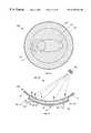
- the present inventionis not limited to antenna reflectors having concentric zones but may be implemented with a reflector body 176 having a plurality of zones 178 - 184 located within the reflector body 176 , with each zone 178 - 184 being of a preselected shape and dimension.
- the illumination source 186is configured to generate three RF signals, depicted by the lines marked 188 - 192 .
- the first and second zones 178 and 180are configured to reflect the first RF signal 188 generating a first antenna pattern 194 therefrom whereas the third 182 and fourth 184 zones are configured to pass the first RF signal 188 .
- the second 180 and third 182 zonesare configured to reflect the second RF signal 190 generating a second antenna pattern 196 therefrom whereas the first 178 and fourth 184 zones are configured to pass the second RF signal 190 . All four zones 178 - 184 are configured to reflect the third RF signal 192 and generate a third antenna pattern 198 therefrom.
- the portions of the first 188 and second 190 RF signals which pass through zones 178 - 184 of the reflector body 176can create problems in other electronic components (not shown) being in a close proximity to the reflector body 176 .
- RF absorbing material 200can be attached to the bottom side 202 of the reflector body 176 and absorb the passed through RF signals 188 - 190 .
- the antenna patterns 196 - 198 generated from a reflector body 176it is typically desirable for the antenna patterns 196 - 198 generated from a reflector body 176 to have low sidelobe levels 204 - 208 .
- a ring of resistive material 210such as R-cardTM manufactured by Southwall Technologies Corporation located in Palo Alto, Calif. can be coupled to the reflector body 176 .
- R-cardTMmanufactured by Southwall Technologies Corporation located in Palo Alto, Calif.
- the present inventionutilizes a preselected plurality of frequency selective and/or polarization sensitive zones to provide multiple antenna patterns from a single reflector antenna.
- each zoneBy configuring each zone to a preselected shape and dimension, the present invention generates a plurality of antenna patterns from a single reflector body with each antenna pattern having a desired shape and beamwidth. In this manner, a single reflector can replace multiple reflector antennas saving weight, cost and real estate.
Landscapes
- Physics & Mathematics (AREA)
- Engineering & Computer Science (AREA)
- Astronomy & Astrophysics (AREA)
- General Physics & Mathematics (AREA)
- Remote Sensing (AREA)
- Aviation & Aerospace Engineering (AREA)
- Aerials With Secondary Devices (AREA)
- Variable-Direction Aerials And Aerial Arrays (AREA)
- Details Of Aerials (AREA)
Abstract
Description
Claims (15)
Priority Applications (5)
| Application Number | Priority Date | Filing Date | Title |
|---|---|---|---|
| US09/232,899US6169524B1 (en) | 1999-01-15 | 1999-01-15 | Multi-pattern antenna having frequency selective or polarization sensitive zones |
| CA002293189ACA2293189C (en) | 1999-01-15 | 1999-12-29 | Multi-pattern antenna having frequency selective or polarization sensitive zones |
| DE60015822TDE60015822T2 (en) | 1999-01-15 | 2000-01-13 | Multi-lobe antenna with frequency-selective or polarization-sensitive zones |
| EP00100186AEP1020953B1 (en) | 1999-01-15 | 2000-01-13 | Multi-pattern antenna having frequency selective or polarization sensitive zones |
| JP2000005493AJP2000216623A (en) | 1999-01-15 | 2000-01-14 | Multiple pattern antenna having frequency selection zone or polarized wave sensing zone |
Applications Claiming Priority (1)
| Application Number | Priority Date | Filing Date | Title |
|---|---|---|---|
| US09/232,899US6169524B1 (en) | 1999-01-15 | 1999-01-15 | Multi-pattern antenna having frequency selective or polarization sensitive zones |
Publications (1)
| Publication Number | Publication Date |
|---|---|
| US6169524B1true US6169524B1 (en) | 2001-01-02 |
Family
ID=22875050
Family Applications (1)
| Application Number | Title | Priority Date | Filing Date |
|---|---|---|---|
| US09/232,899Expired - LifetimeUS6169524B1 (en) | 1999-01-15 | 1999-01-15 | Multi-pattern antenna having frequency selective or polarization sensitive zones |
Country Status (5)
| Country | Link |
|---|---|
| US (1) | US6169524B1 (en) |
| EP (1) | EP1020953B1 (en) |
| JP (1) | JP2000216623A (en) |
| CA (1) | CA2293189C (en) |
| DE (1) | DE60015822T2 (en) |
Cited By (11)
| Publication number | Priority date | Publication date | Assignee | Title |
|---|---|---|---|---|
| US20020118140A1 (en)* | 1999-10-14 | 2002-08-29 | Kabushiki Kaisha Toyota Chuo Kenkyusho | Antenna system |
| US6608607B2 (en) | 2001-11-27 | 2003-08-19 | Northrop Grumman Corporation | High performance multi-band frequency selective reflector with equal beam coverage |
| US7737903B1 (en)* | 2005-06-27 | 2010-06-15 | Lockheed Martin Corporation | Stepped-reflector antenna for satellite communication payloads |
| US7994962B1 (en) | 2007-07-17 | 2011-08-09 | Drosera Ltd. | Apparatus and method for concentrating electromagnetic energy on a remotely-located object |
| US20110215190A1 (en)* | 2009-06-19 | 2011-09-08 | Mbda Uk Limited | Antennas |
| JP6218990B1 (en)* | 2016-12-13 | 2017-10-25 | 三菱電機株式会社 | Reflector antenna device |
| US10862203B2 (en)* | 2013-11-11 | 2020-12-08 | Gogo Business Aviation Llc | Radome having localized areas of reduced radio signal attenuation |
| US11063348B2 (en)* | 2017-03-22 | 2021-07-13 | Nec Corporation | Radome and pattern forming method |
| US20230216208A1 (en)* | 2021-12-30 | 2023-07-06 | The Boeing Company | Confocal antenna system |
| CN116759795A (en)* | 2023-08-11 | 2023-09-15 | 中国科学院地质与地球物理研究所 | All-sky meteor radar transmitting antenna system |
| CN120254803A (en)* | 2025-06-09 | 2025-07-04 | 石家庄世联达科技有限公司 | Rapid testing method of radar scattering based on polarization decomposition |
Families Citing this family (152)
| Publication number | Priority date | Publication date | Assignee | Title |
|---|---|---|---|---|
| US6285332B1 (en)* | 1999-09-10 | 2001-09-04 | Trw Inc. | Frequency selective reflector |
| JP2004304737A (en) | 2003-04-01 | 2004-10-28 | Seiko Epson Corp | Antenna device and method of manufacturing the same |
| FR2868611B1 (en)* | 2004-04-02 | 2006-07-21 | Alcatel Sa | REFLECTIVE ANTENNA HAVING A 3D STRUCTURE FOR FORMING WAVE BEAMS BELONGING TO DIFFERENT FREQUENCY BANDS |
| JP5207713B2 (en)* | 2007-11-29 | 2013-06-12 | 上田日本無線株式会社 | Reflector for millimeter wave radar |
| US9113347B2 (en) | 2012-12-05 | 2015-08-18 | At&T Intellectual Property I, Lp | Backhaul link for distributed antenna system |
| US10009065B2 (en) | 2012-12-05 | 2018-06-26 | At&T Intellectual Property I, L.P. | Backhaul link for distributed antenna system |
| US9525524B2 (en) | 2013-05-31 | 2016-12-20 | At&T Intellectual Property I, L.P. | Remote distributed antenna system |
| US9999038B2 (en) | 2013-05-31 | 2018-06-12 | At&T Intellectual Property I, L.P. | Remote distributed antenna system |
| US8897697B1 (en) | 2013-11-06 | 2014-11-25 | At&T Intellectual Property I, Lp | Millimeter-wave surface-wave communications |
| FR3018638B1 (en)* | 2014-03-14 | 2017-07-07 | Centre Nat D'etudes Spatiales (Cnes) | MULTI-SECTOR ABSORPTION DEVICE AND METHOD |
| US9692101B2 (en) | 2014-08-26 | 2017-06-27 | At&T Intellectual Property I, L.P. | Guided wave couplers for coupling electromagnetic waves between a waveguide surface and a surface of a wire |
| US9768833B2 (en) | 2014-09-15 | 2017-09-19 | At&T Intellectual Property I, L.P. | Method and apparatus for sensing a condition in a transmission medium of electromagnetic waves |
| US10063280B2 (en) | 2014-09-17 | 2018-08-28 | At&T Intellectual Property I, L.P. | Monitoring and mitigating conditions in a communication network |
| US9615269B2 (en) | 2014-10-02 | 2017-04-04 | At&T Intellectual Property I, L.P. | Method and apparatus that provides fault tolerance in a communication network |
| US9685992B2 (en) | 2014-10-03 | 2017-06-20 | At&T Intellectual Property I, L.P. | Circuit panel network and methods thereof |
| US9503189B2 (en) | 2014-10-10 | 2016-11-22 | At&T Intellectual Property I, L.P. | Method and apparatus for arranging communication sessions in a communication system |
| US9973299B2 (en) | 2014-10-14 | 2018-05-15 | At&T Intellectual Property I, L.P. | Method and apparatus for adjusting a mode of communication in a communication network |
| US9762289B2 (en) | 2014-10-14 | 2017-09-12 | At&T Intellectual Property I, L.P. | Method and apparatus for transmitting or receiving signals in a transportation system |
| US9312919B1 (en) | 2014-10-21 | 2016-04-12 | At&T Intellectual Property I, Lp | Transmission device with impairment compensation and methods for use therewith |
| US9520945B2 (en) | 2014-10-21 | 2016-12-13 | At&T Intellectual Property I, L.P. | Apparatus for providing communication services and methods thereof |
| US9769020B2 (en) | 2014-10-21 | 2017-09-19 | At&T Intellectual Property I, L.P. | Method and apparatus for responding to events affecting communications in a communication network |
| US9627768B2 (en) | 2014-10-21 | 2017-04-18 | At&T Intellectual Property I, L.P. | Guided-wave transmission device with non-fundamental mode propagation and methods for use therewith |
| US9653770B2 (en) | 2014-10-21 | 2017-05-16 | At&T Intellectual Property I, L.P. | Guided wave coupler, coupling module and methods for use therewith |
| US9577306B2 (en) | 2014-10-21 | 2017-02-21 | At&T Intellectual Property I, L.P. | Guided-wave transmission device and methods for use therewith |
| US9780834B2 (en) | 2014-10-21 | 2017-10-03 | At&T Intellectual Property I, L.P. | Method and apparatus for transmitting electromagnetic waves |
| US10009067B2 (en) | 2014-12-04 | 2018-06-26 | At&T Intellectual Property I, L.P. | Method and apparatus for configuring a communication interface |
| US9461706B1 (en) | 2015-07-31 | 2016-10-04 | At&T Intellectual Property I, Lp | Method and apparatus for exchanging communication signals |
| US9544006B2 (en) | 2014-11-20 | 2017-01-10 | At&T Intellectual Property I, L.P. | Transmission device with mode division multiplexing and methods for use therewith |
| US10340573B2 (en) | 2016-10-26 | 2019-07-02 | At&T Intellectual Property I, L.P. | Launcher with cylindrical coupling device and methods for use therewith |
| US9954287B2 (en) | 2014-11-20 | 2018-04-24 | At&T Intellectual Property I, L.P. | Apparatus for converting wireless signals and electromagnetic waves and methods thereof |
| US9742462B2 (en) | 2014-12-04 | 2017-08-22 | At&T Intellectual Property I, L.P. | Transmission medium and communication interfaces and methods for use therewith |
| US9800327B2 (en) | 2014-11-20 | 2017-10-24 | At&T Intellectual Property I, L.P. | Apparatus for controlling operations of a communication device and methods thereof |
| US10243784B2 (en) | 2014-11-20 | 2019-03-26 | At&T Intellectual Property I, L.P. | System for generating topology information and methods thereof |
| US9997819B2 (en) | 2015-06-09 | 2018-06-12 | At&T Intellectual Property I, L.P. | Transmission medium and method for facilitating propagation of electromagnetic waves via a core |
| US10144036B2 (en) | 2015-01-30 | 2018-12-04 | At&T Intellectual Property I, L.P. | Method and apparatus for mitigating interference affecting a propagation of electromagnetic waves guided by a transmission medium |
| US9876570B2 (en) | 2015-02-20 | 2018-01-23 | At&T Intellectual Property I, Lp | Guided-wave transmission device with non-fundamental mode propagation and methods for use therewith |
| US9749013B2 (en) | 2015-03-17 | 2017-08-29 | At&T Intellectual Property I, L.P. | Method and apparatus for reducing attenuation of electromagnetic waves guided by a transmission medium |
| US10224981B2 (en) | 2015-04-24 | 2019-03-05 | At&T Intellectual Property I, Lp | Passive electrical coupling device and methods for use therewith |
| US9705561B2 (en) | 2015-04-24 | 2017-07-11 | At&T Intellectual Property I, L.P. | Directional coupling device and methods for use therewith |
| US9793954B2 (en) | 2015-04-28 | 2017-10-17 | At&T Intellectual Property I, L.P. | Magnetic coupling device and methods for use therewith |
| US9948354B2 (en) | 2015-04-28 | 2018-04-17 | At&T Intellectual Property I, L.P. | Magnetic coupling device with reflective plate and methods for use therewith |
| US9748626B2 (en) | 2015-05-14 | 2017-08-29 | At&T Intellectual Property I, L.P. | Plurality of cables having different cross-sectional shapes which are bundled together to form a transmission medium |
| US9490869B1 (en) | 2015-05-14 | 2016-11-08 | At&T Intellectual Property I, L.P. | Transmission medium having multiple cores and methods for use therewith |
| US9871282B2 (en) | 2015-05-14 | 2018-01-16 | At&T Intellectual Property I, L.P. | At least one transmission medium having a dielectric surface that is covered at least in part by a second dielectric |
| US10650940B2 (en) | 2015-05-15 | 2020-05-12 | At&T Intellectual Property I, L.P. | Transmission medium having a conductive material and methods for use therewith |
| US9917341B2 (en) | 2015-05-27 | 2018-03-13 | At&T Intellectual Property I, L.P. | Apparatus and method for launching electromagnetic waves and for modifying radial dimensions of the propagating electromagnetic waves |
| US10103801B2 (en) | 2015-06-03 | 2018-10-16 | At&T Intellectual Property I, L.P. | Host node device and methods for use therewith |
| US9866309B2 (en) | 2015-06-03 | 2018-01-09 | At&T Intellectual Property I, Lp | Host node device and methods for use therewith |
| US9912381B2 (en) | 2015-06-03 | 2018-03-06 | At&T Intellectual Property I, Lp | Network termination and methods for use therewith |
| US10812174B2 (en) | 2015-06-03 | 2020-10-20 | At&T Intellectual Property I, L.P. | Client node device and methods for use therewith |
| US9913139B2 (en) | 2015-06-09 | 2018-03-06 | At&T Intellectual Property I, L.P. | Signal fingerprinting for authentication of communicating devices |
| US10142086B2 (en) | 2015-06-11 | 2018-11-27 | At&T Intellectual Property I, L.P. | Repeater and methods for use therewith |
| US9608692B2 (en) | 2015-06-11 | 2017-03-28 | At&T Intellectual Property I, L.P. | Repeater and methods for use therewith |
| US9820146B2 (en) | 2015-06-12 | 2017-11-14 | At&T Intellectual Property I, L.P. | Method and apparatus for authentication and identity management of communicating devices |
| US9667317B2 (en) | 2015-06-15 | 2017-05-30 | At&T Intellectual Property I, L.P. | Method and apparatus for providing security using network traffic adjustments |
| US9509415B1 (en) | 2015-06-25 | 2016-11-29 | At&T Intellectual Property I, L.P. | Methods and apparatus for inducing a fundamental wave mode on a transmission medium |
| US9640850B2 (en) | 2015-06-25 | 2017-05-02 | At&T Intellectual Property I, L.P. | Methods and apparatus for inducing a non-fundamental wave mode on a transmission medium |
| US9865911B2 (en) | 2015-06-25 | 2018-01-09 | At&T Intellectual Property I, L.P. | Waveguide system for slot radiating first electromagnetic waves that are combined into a non-fundamental wave mode second electromagnetic wave on a transmission medium |
| US9628116B2 (en) | 2015-07-14 | 2017-04-18 | At&T Intellectual Property I, L.P. | Apparatus and methods for transmitting wireless signals |
| US9882257B2 (en) | 2015-07-14 | 2018-01-30 | At&T Intellectual Property I, L.P. | Method and apparatus for launching a wave mode that mitigates interference |
| US10148016B2 (en) | 2015-07-14 | 2018-12-04 | At&T Intellectual Property I, L.P. | Apparatus and methods for communicating utilizing an antenna array |
| US9847566B2 (en) | 2015-07-14 | 2017-12-19 | At&T Intellectual Property I, L.P. | Method and apparatus for adjusting a field of a signal to mitigate interference |
| US10033107B2 (en) | 2015-07-14 | 2018-07-24 | At&T Intellectual Property I, L.P. | Method and apparatus for coupling an antenna to a device |
| US10341142B2 (en) | 2015-07-14 | 2019-07-02 | At&T Intellectual Property I, L.P. | Apparatus and methods for generating non-interfering electromagnetic waves on an uninsulated conductor |
| US10044409B2 (en) | 2015-07-14 | 2018-08-07 | At&T Intellectual Property I, L.P. | Transmission medium and methods for use therewith |
| US10170840B2 (en) | 2015-07-14 | 2019-01-01 | At&T Intellectual Property I, L.P. | Apparatus and methods for sending or receiving electromagnetic signals |
| US10205655B2 (en) | 2015-07-14 | 2019-02-12 | At&T Intellectual Property I, L.P. | Apparatus and methods for communicating utilizing an antenna array and multiple communication paths |
| US10320586B2 (en) | 2015-07-14 | 2019-06-11 | At&T Intellectual Property I, L.P. | Apparatus and methods for generating non-interfering electromagnetic waves on an insulated transmission medium |
| US9853342B2 (en) | 2015-07-14 | 2017-12-26 | At&T Intellectual Property I, L.P. | Dielectric transmission medium connector and methods for use therewith |
| US9722318B2 (en) | 2015-07-14 | 2017-08-01 | At&T Intellectual Property I, L.P. | Method and apparatus for coupling an antenna to a device |
| US10033108B2 (en) | 2015-07-14 | 2018-07-24 | At&T Intellectual Property I, L.P. | Apparatus and methods for generating an electromagnetic wave having a wave mode that mitigates interference |
| US9608740B2 (en) | 2015-07-15 | 2017-03-28 | At&T Intellectual Property I, L.P. | Method and apparatus for launching a wave mode that mitigates interference |
| US9793951B2 (en) | 2015-07-15 | 2017-10-17 | At&T Intellectual Property I, L.P. | Method and apparatus for launching a wave mode that mitigates interference |
| US10090606B2 (en) | 2015-07-15 | 2018-10-02 | At&T Intellectual Property I, L.P. | Antenna system with dielectric array and methods for use therewith |
| US9749053B2 (en) | 2015-07-23 | 2017-08-29 | At&T Intellectual Property I, L.P. | Node device, repeater and methods for use therewith |
| US9948333B2 (en) | 2015-07-23 | 2018-04-17 | At&T Intellectual Property I, L.P. | Method and apparatus for wireless communications to mitigate interference |
| US9912027B2 (en) | 2015-07-23 | 2018-03-06 | At&T Intellectual Property I, L.P. | Method and apparatus for exchanging communication signals |
| US9871283B2 (en) | 2015-07-23 | 2018-01-16 | At&T Intellectual Property I, Lp | Transmission medium having a dielectric core comprised of plural members connected by a ball and socket configuration |
| US9735833B2 (en) | 2015-07-31 | 2017-08-15 | At&T Intellectual Property I, L.P. | Method and apparatus for communications management in a neighborhood network |
| US9967173B2 (en) | 2015-07-31 | 2018-05-08 | At&T Intellectual Property I, L.P. | Method and apparatus for authentication and identity management of communicating devices |
| US9904535B2 (en) | 2015-09-14 | 2018-02-27 | At&T Intellectual Property I, L.P. | Method and apparatus for distributing software |
| US10136434B2 (en) | 2015-09-16 | 2018-11-20 | At&T Intellectual Property I, L.P. | Method and apparatus for use with a radio distributed antenna system having an ultra-wideband control channel |
| US10079661B2 (en) | 2015-09-16 | 2018-09-18 | At&T Intellectual Property I, L.P. | Method and apparatus for use with a radio distributed antenna system having a clock reference |
| US10009063B2 (en) | 2015-09-16 | 2018-06-26 | At&T Intellectual Property I, L.P. | Method and apparatus for use with a radio distributed antenna system having an out-of-band reference signal |
| US9769128B2 (en) | 2015-09-28 | 2017-09-19 | At&T Intellectual Property I, L.P. | Method and apparatus for encryption of communications over a network |
| US9729197B2 (en) | 2015-10-01 | 2017-08-08 | At&T Intellectual Property I, L.P. | Method and apparatus for communicating network management traffic over a network |
| US9876264B2 (en) | 2015-10-02 | 2018-01-23 | At&T Intellectual Property I, Lp | Communication system, guided wave switch and methods for use therewith |
| US10355367B2 (en) | 2015-10-16 | 2019-07-16 | At&T Intellectual Property I, L.P. | Antenna structure for exchanging wireless signals |
| US10665942B2 (en) | 2015-10-16 | 2020-05-26 | At&T Intellectual Property I, L.P. | Method and apparatus for adjusting wireless communications |
| US9912419B1 (en) | 2016-08-24 | 2018-03-06 | At&T Intellectual Property I, L.P. | Method and apparatus for managing a fault in a distributed antenna system |
| US9860075B1 (en) | 2016-08-26 | 2018-01-02 | At&T Intellectual Property I, L.P. | Method and communication node for broadband distribution |
| US10291311B2 (en) | 2016-09-09 | 2019-05-14 | At&T Intellectual Property I, L.P. | Method and apparatus for mitigating a fault in a distributed antenna system |
| US11032819B2 (en) | 2016-09-15 | 2021-06-08 | At&T Intellectual Property I, L.P. | Method and apparatus for use with a radio distributed antenna system having a control channel reference signal |
| US10135147B2 (en) | 2016-10-18 | 2018-11-20 | At&T Intellectual Property I, L.P. | Apparatus and methods for launching guided waves via an antenna |
| US10340600B2 (en) | 2016-10-18 | 2019-07-02 | At&T Intellectual Property I, L.P. | Apparatus and methods for launching guided waves via plural waveguide systems |
| US10135146B2 (en) | 2016-10-18 | 2018-11-20 | At&T Intellectual Property I, L.P. | Apparatus and methods for launching guided waves via circuits |
| US10374316B2 (en) | 2016-10-21 | 2019-08-06 | At&T Intellectual Property I, L.P. | System and dielectric antenna with non-uniform dielectric |
| US9876605B1 (en) | 2016-10-21 | 2018-01-23 | At&T Intellectual Property I, L.P. | Launcher and coupling system to support desired guided wave mode |
| KR101823365B1 (en)* | 2016-10-21 | 2018-03-14 | 연세대학교 산학협력단 | Folded Reflectarray Antenna and Polarizing Grid Substrate |
| US9991580B2 (en) | 2016-10-21 | 2018-06-05 | At&T Intellectual Property I, L.P. | Launcher and coupling system for guided wave mode cancellation |
| US10811767B2 (en) | 2016-10-21 | 2020-10-20 | At&T Intellectual Property I, L.P. | System and dielectric antenna with convex dielectric radome |
| US10312567B2 (en) | 2016-10-26 | 2019-06-04 | At&T Intellectual Property I, L.P. | Launcher with planar strip antenna and methods for use therewith |
| US10225025B2 (en) | 2016-11-03 | 2019-03-05 | At&T Intellectual Property I, L.P. | Method and apparatus for detecting a fault in a communication system |
| US10291334B2 (en) | 2016-11-03 | 2019-05-14 | At&T Intellectual Property I, L.P. | System for detecting a fault in a communication system |
| US10224634B2 (en) | 2016-11-03 | 2019-03-05 | At&T Intellectual Property I, L.P. | Methods and apparatus for adjusting an operational characteristic of an antenna |
| US10498044B2 (en) | 2016-11-03 | 2019-12-03 | At&T Intellectual Property I, L.P. | Apparatus for configuring a surface of an antenna |
| US10178445B2 (en) | 2016-11-23 | 2019-01-08 | At&T Intellectual Property I, L.P. | Methods, devices, and systems for load balancing between a plurality of waveguides |
| US10090594B2 (en) | 2016-11-23 | 2018-10-02 | At&T Intellectual Property I, L.P. | Antenna system having structural configurations for assembly |
| US10340603B2 (en) | 2016-11-23 | 2019-07-02 | At&T Intellectual Property I, L.P. | Antenna system having shielded structural configurations for assembly |
| US10535928B2 (en) | 2016-11-23 | 2020-01-14 | At&T Intellectual Property I, L.P. | Antenna system and methods for use therewith |
| US10340601B2 (en) | 2016-11-23 | 2019-07-02 | At&T Intellectual Property I, L.P. | Multi-antenna system and methods for use therewith |
| US10361489B2 (en) | 2016-12-01 | 2019-07-23 | At&T Intellectual Property I, L.P. | Dielectric dish antenna system and methods for use therewith |
| US10305190B2 (en) | 2016-12-01 | 2019-05-28 | At&T Intellectual Property I, L.P. | Reflecting dielectric antenna system and methods for use therewith |
| US10755542B2 (en) | 2016-12-06 | 2020-08-25 | At&T Intellectual Property I, L.P. | Method and apparatus for surveillance via guided wave communication |
| US10727599B2 (en) | 2016-12-06 | 2020-07-28 | At&T Intellectual Property I, L.P. | Launcher with slot antenna and methods for use therewith |
| US10326494B2 (en) | 2016-12-06 | 2019-06-18 | At&T Intellectual Property I, L.P. | Apparatus for measurement de-embedding and methods for use therewith |
| US10135145B2 (en) | 2016-12-06 | 2018-11-20 | At&T Intellectual Property I, L.P. | Apparatus and methods for generating an electromagnetic wave along a transmission medium |
| US9927517B1 (en) | 2016-12-06 | 2018-03-27 | At&T Intellectual Property I, L.P. | Apparatus and methods for sensing rainfall |
| US10020844B2 (en) | 2016-12-06 | 2018-07-10 | T&T Intellectual Property I, L.P. | Method and apparatus for broadcast communication via guided waves |
| US10819035B2 (en) | 2016-12-06 | 2020-10-27 | At&T Intellectual Property I, L.P. | Launcher with helical antenna and methods for use therewith |
| US10439675B2 (en) | 2016-12-06 | 2019-10-08 | At&T Intellectual Property I, L.P. | Method and apparatus for repeating guided wave communication signals |
| US10637149B2 (en) | 2016-12-06 | 2020-04-28 | At&T Intellectual Property I, L.P. | Injection molded dielectric antenna and methods for use therewith |
| US10382976B2 (en) | 2016-12-06 | 2019-08-13 | At&T Intellectual Property I, L.P. | Method and apparatus for managing wireless communications based on communication paths and network device positions |
| US10694379B2 (en) | 2016-12-06 | 2020-06-23 | At&T Intellectual Property I, L.P. | Waveguide system with device-based authentication and methods for use therewith |
| US10168695B2 (en) | 2016-12-07 | 2019-01-01 | At&T Intellectual Property I, L.P. | Method and apparatus for controlling an unmanned aircraft |
| US9893795B1 (en) | 2016-12-07 | 2018-02-13 | At&T Intellectual Property I, Lp | Method and repeater for broadband distribution |
| US10027397B2 (en) | 2016-12-07 | 2018-07-17 | At&T Intellectual Property I, L.P. | Distributed antenna system and methods for use therewith |
| US10243270B2 (en) | 2016-12-07 | 2019-03-26 | At&T Intellectual Property I, L.P. | Beam adaptive multi-feed dielectric antenna system and methods for use therewith |
| US10389029B2 (en) | 2016-12-07 | 2019-08-20 | At&T Intellectual Property I, L.P. | Multi-feed dielectric antenna system with core selection and methods for use therewith |
| US10139820B2 (en) | 2016-12-07 | 2018-11-27 | At&T Intellectual Property I, L.P. | Method and apparatus for deploying equipment of a communication system |
| US10547348B2 (en) | 2016-12-07 | 2020-01-28 | At&T Intellectual Property I, L.P. | Method and apparatus for switching transmission mediums in a communication system |
| US10359749B2 (en) | 2016-12-07 | 2019-07-23 | At&T Intellectual Property I, L.P. | Method and apparatus for utilities management via guided wave communication |
| US10446936B2 (en) | 2016-12-07 | 2019-10-15 | At&T Intellectual Property I, L.P. | Multi-feed dielectric antenna system and methods for use therewith |
| US10103422B2 (en) | 2016-12-08 | 2018-10-16 | At&T Intellectual Property I, L.P. | Method and apparatus for mounting network devices |
| US10916969B2 (en) | 2016-12-08 | 2021-02-09 | At&T Intellectual Property I, L.P. | Method and apparatus for providing power using an inductive coupling |
| US9911020B1 (en) | 2016-12-08 | 2018-03-06 | At&T Intellectual Property I, L.P. | Method and apparatus for tracking via a radio frequency identification device |
| US10530505B2 (en) | 2016-12-08 | 2020-01-07 | At&T Intellectual Property I, L.P. | Apparatus and methods for launching electromagnetic waves along a transmission medium |
| US10389037B2 (en) | 2016-12-08 | 2019-08-20 | At&T Intellectual Property I, L.P. | Apparatus and methods for selecting sections of an antenna array and use therewith |
| US10326689B2 (en) | 2016-12-08 | 2019-06-18 | At&T Intellectual Property I, L.P. | Method and system for providing alternative communication paths |
| US10777873B2 (en) | 2016-12-08 | 2020-09-15 | At&T Intellectual Property I, L.P. | Method and apparatus for mounting network devices |
| US10411356B2 (en) | 2016-12-08 | 2019-09-10 | At&T Intellectual Property I, L.P. | Apparatus and methods for selectively targeting communication devices with an antenna array |
| US10069535B2 (en) | 2016-12-08 | 2018-09-04 | At&T Intellectual Property I, L.P. | Apparatus and methods for launching electromagnetic waves having a certain electric field structure |
| US10938108B2 (en) | 2016-12-08 | 2021-03-02 | At&T Intellectual Property I, L.P. | Frequency selective multi-feed dielectric antenna system and methods for use therewith |
| US10601494B2 (en) | 2016-12-08 | 2020-03-24 | At&T Intellectual Property I, L.P. | Dual-band communication device and method for use therewith |
| US9998870B1 (en) | 2016-12-08 | 2018-06-12 | At&T Intellectual Property I, L.P. | Method and apparatus for proximity sensing |
| US10264586B2 (en) | 2016-12-09 | 2019-04-16 | At&T Mobility Ii Llc | Cloud-based packet controller and methods for use therewith |
| US9838896B1 (en) | 2016-12-09 | 2017-12-05 | At&T Intellectual Property I, L.P. | Method and apparatus for assessing network coverage |
| US10340983B2 (en) | 2016-12-09 | 2019-07-02 | At&T Intellectual Property I, L.P. | Method and apparatus for surveying remote sites via guided wave communications |
| US10461435B2 (en) | 2016-12-29 | 2019-10-29 | Tionesta, Llc | Multiple tuned Fresnel zone plate reflector antenna |
| US9973940B1 (en) | 2017-02-27 | 2018-05-15 | At&T Intellectual Property I, L.P. | Apparatus and methods for dynamic impedance matching of a guided wave launcher |
| US10298293B2 (en) | 2017-03-13 | 2019-05-21 | At&T Intellectual Property I, L.P. | Apparatus of communication utilizing wireless network devices |
| KR101943857B1 (en)* | 2017-12-06 | 2019-01-30 | 연세대학교 산학협력단 | Reflect array and Reflect array Antenna having the same |
Citations (7)
| Publication number | Priority date | Publication date | Assignee | Title |
|---|---|---|---|---|
| US3189907A (en)* | 1961-08-11 | 1965-06-15 | Lylnan F Van Buskirk | Zone plate radio transmission system |
| US4757323A (en)* | 1984-07-17 | 1988-07-12 | Alcatel Thomson Espace | Crossed polarization same-zone two-frequency antenna for telecommunications satellites |
| US4831384A (en)* | 1988-05-31 | 1989-05-16 | Tecom Industries Incorporated | Polarization-sensitive receiver for microwave signals |
| US4851858A (en)* | 1984-01-26 | 1989-07-25 | Messerschmitt-Boelkow-Blohm Gmbh | Reflector antenna for operation in more than one frequency band |
| US4905014A (en)* | 1988-04-05 | 1990-02-27 | Malibu Research Associates, Inc. | Microwave phasing structures for electromagnetically emulating reflective surfaces and focusing elements of selected geometry |
| US5136294A (en)* | 1987-01-12 | 1992-08-04 | Nec Corporation | Multibeam antenna |
| US5365245A (en)* | 1993-05-06 | 1994-11-15 | The United States Of America As Represented By The Secretary Of The Navy | Hybrid orthogonal transverse electromagnetic fed reflector antenna |
Family Cites Families (4)
| Publication number | Priority date | Publication date | Assignee | Title |
|---|---|---|---|---|
| FR2304192A1 (en)* | 1975-03-14 | 1976-10-08 | Thomson Csf | SELECTIVE GAIN REDUCTION ANTENNA |
| US4348677A (en)* | 1979-06-25 | 1982-09-07 | General Dynamics, Pomona Division | Common aperture dual mode seeker antenna |
| CA2105745C (en)* | 1992-09-21 | 1997-12-16 | Parthasarathy Ramanujam | Identical surface shaped reflectors in semi-tandem arrangement |
| US5977926A (en)* | 1998-09-10 | 1999-11-02 | Trw Inc. | Multi-focus reflector antenna |
- 1999
- 1999-01-15USUS09/232,899patent/US6169524B1/ennot_activeExpired - Lifetime
- 1999-12-29CACA002293189Apatent/CA2293189C/ennot_activeExpired - Fee Related
- 2000
- 2000-01-13DEDE60015822Tpatent/DE60015822T2/ennot_activeExpired - Fee Related
- 2000-01-13EPEP00100186Apatent/EP1020953B1/ennot_activeExpired - Lifetime
- 2000-01-14JPJP2000005493Apatent/JP2000216623A/enactivePending
Patent Citations (7)
| Publication number | Priority date | Publication date | Assignee | Title |
|---|---|---|---|---|
| US3189907A (en)* | 1961-08-11 | 1965-06-15 | Lylnan F Van Buskirk | Zone plate radio transmission system |
| US4851858A (en)* | 1984-01-26 | 1989-07-25 | Messerschmitt-Boelkow-Blohm Gmbh | Reflector antenna for operation in more than one frequency band |
| US4757323A (en)* | 1984-07-17 | 1988-07-12 | Alcatel Thomson Espace | Crossed polarization same-zone two-frequency antenna for telecommunications satellites |
| US5136294A (en)* | 1987-01-12 | 1992-08-04 | Nec Corporation | Multibeam antenna |
| US4905014A (en)* | 1988-04-05 | 1990-02-27 | Malibu Research Associates, Inc. | Microwave phasing structures for electromagnetically emulating reflective surfaces and focusing elements of selected geometry |
| US4831384A (en)* | 1988-05-31 | 1989-05-16 | Tecom Industries Incorporated | Polarization-sensitive receiver for microwave signals |
| US5365245A (en)* | 1993-05-06 | 1994-11-15 | The United States Of America As Represented By The Secretary Of The Navy | Hybrid orthogonal transverse electromagnetic fed reflector antenna |
Non-Patent Citations (1)
| Title |
|---|
| Lee, et al., "Compound Reflector Antennas," published in the IEEE Proceedings on Antennas and Propagation, Apr. 1992, pp. 135-138. |
Cited By (17)
| Publication number | Priority date | Publication date | Assignee | Title |
|---|---|---|---|---|
| US6972730B2 (en) | 1999-10-14 | 2005-12-06 | Kabushiki Kaisha Toyota Chuo Kenkyusho | Antenna system |
| US20020118140A1 (en)* | 1999-10-14 | 2002-08-29 | Kabushiki Kaisha Toyota Chuo Kenkyusho | Antenna system |
| US6608607B2 (en) | 2001-11-27 | 2003-08-19 | Northrop Grumman Corporation | High performance multi-band frequency selective reflector with equal beam coverage |
| US6747608B2 (en) | 2001-11-27 | 2004-06-08 | Northrop Grumman Corporation | High performance multi-band frequency selective reflector with equal beam coverage |
| US7737903B1 (en)* | 2005-06-27 | 2010-06-15 | Lockheed Martin Corporation | Stepped-reflector antenna for satellite communication payloads |
| US7994962B1 (en) | 2007-07-17 | 2011-08-09 | Drosera Ltd. | Apparatus and method for concentrating electromagnetic energy on a remotely-located object |
| US20110215190A1 (en)* | 2009-06-19 | 2011-09-08 | Mbda Uk Limited | Antennas |
| US8680450B2 (en)* | 2009-06-19 | 2014-03-25 | Mbda Uk Limited | Antennas |
| US10862203B2 (en)* | 2013-11-11 | 2020-12-08 | Gogo Business Aviation Llc | Radome having localized areas of reduced radio signal attenuation |
| JP6218990B1 (en)* | 2016-12-13 | 2017-10-25 | 三菱電機株式会社 | Reflector antenna device |
| US10797401B2 (en)* | 2016-12-13 | 2020-10-06 | Mitsubishi Electric Corporation | Reflection mirror antenna device |
| US11063348B2 (en)* | 2017-03-22 | 2021-07-13 | Nec Corporation | Radome and pattern forming method |
| US20230216208A1 (en)* | 2021-12-30 | 2023-07-06 | The Boeing Company | Confocal antenna system |
| US12051853B2 (en)* | 2021-12-30 | 2024-07-30 | The Boeing Company | Confocal antenna system |
| CN116759795A (en)* | 2023-08-11 | 2023-09-15 | 中国科学院地质与地球物理研究所 | All-sky meteor radar transmitting antenna system |
| CN116759795B (en)* | 2023-08-11 | 2023-11-17 | 中国科学院地质与地球物理研究所 | An all-sky meteor radar transmitting antenna system |
| CN120254803A (en)* | 2025-06-09 | 2025-07-04 | 石家庄世联达科技有限公司 | Rapid testing method of radar scattering based on polarization decomposition |
Also Published As
| Publication number | Publication date |
|---|---|
| DE60015822D1 (en) | 2004-12-23 |
| EP1020953B1 (en) | 2004-11-17 |
| JP2000216623A (en) | 2000-08-04 |
| CA2293189A1 (en) | 2000-07-15 |
| DE60015822T2 (en) | 2005-03-31 |
| EP1020953A3 (en) | 2003-02-05 |
| EP1020953A2 (en) | 2000-07-19 |
| CA2293189C (en) | 2001-12-25 |
Similar Documents
| Publication | Publication Date | Title |
|---|---|---|
| US6169524B1 (en) | Multi-pattern antenna having frequency selective or polarization sensitive zones | |
| US6545645B1 (en) | Compact frequency selective reflective antenna | |
| US20240079776A1 (en) | Lens antenna system | |
| CA2140507C (en) | Multiple band folding antenna | |
| US4115782A (en) | Microwave antenna system | |
| US5471224A (en) | Frequency selective surface with repeating pattern of concentric closed conductor paths, and antenna having the surface | |
| US4772890A (en) | Multi-band planar antenna array | |
| US5949387A (en) | Frequency selective surface (FSS) filter for an antenna | |
| US20170179596A1 (en) | Wideband reflectarray antenna for dual polarization applications | |
| US6836258B2 (en) | Complementary dual antenna system | |
| US4851858A (en) | Reflector antenna for operation in more than one frequency band | |
| EP1067630B1 (en) | Reflector with resistive taper in connection with dense packed feeds for cellular spot beam satellite coverage | |
| WO2004008576A1 (en) | Spatial filtering surface operative with antenna aperture for modifying aperture electric field | |
| WO2004008571A2 (en) | Antenna system with spatial filtering surface | |
| US6747608B2 (en) | High performance multi-band frequency selective reflector with equal beam coverage | |
| US6285332B1 (en) | Frequency selective reflector | |
| US6384795B1 (en) | Multi-step circular horn system | |
| Palvig et al. | Design of a modulated fss subreflector for a dual-reflector system | |
| JPH05315826A (en) | Antenna scanned by frequency change | |
| US20040085254A1 (en) | Reflector and antenna system containing reflectors | |
| Budhu et al. | Loading rims of radio telescopes with reconfigurable reflectarrays for adaptive null-steering | |
| CA2058304A1 (en) | Antenna apparatus with reflector or lens consisting of a frequency scanned grating | |
| KR20000022462A (en) | Planar dual frequency array antenna | |
| van Hezewijk | Multiple beam antenna system with microstrip feeds |
Legal Events
| Date | Code | Title | Description |
|---|---|---|---|
| AS | Assignment | Owner name:TRW INC., CALIFORNIA Free format text:ASSIGNMENT OF ASSIGNORS INTEREST;ASSIGNORS:WU, TE-KAO;CHANDLER, CHARLES W.;REEL/FRAME:009715/0738 Effective date:19990114 | |
| STCF | Information on status: patent grant | Free format text:PATENTED CASE | |
| AS | Assignment | Owner name:NORTHROP GRUMMAN CORPORATION, CALIFORNIA Free format text:ASSIGNMENT OF ASSIGNORS INTEREST;ASSIGNOR:TRW, INC. N/K/A NORTHROP GRUMMAN SPACE AND MISSION SYSTEMS CORPORATION, AN OHIO CORPORATION;REEL/FRAME:013751/0849 Effective date:20030122 Owner name:NORTHROP GRUMMAN CORPORATION,CALIFORNIA Free format text:ASSIGNMENT OF ASSIGNORS INTEREST;ASSIGNOR:TRW, INC. N/K/A NORTHROP GRUMMAN SPACE AND MISSION SYSTEMS CORPORATION, AN OHIO CORPORATION;REEL/FRAME:013751/0849 Effective date:20030122 | |
| FEPP | Fee payment procedure | Free format text:PAYOR NUMBER ASSIGNED (ORIGINAL EVENT CODE: ASPN); ENTITY STATUS OF PATENT OWNER: LARGE ENTITY | |
| FPAY | Fee payment | Year of fee payment:4 | |
| FEPP | Fee payment procedure | Free format text:PAYER NUMBER DE-ASSIGNED (ORIGINAL EVENT CODE: RMPN); ENTITY STATUS OF PATENT OWNER: LARGE ENTITY | |
| FPAY | Fee payment | Year of fee payment:8 | |
| AS | Assignment | Owner name:NORTHROP GRUMMAN SPACE & MISSION SYSTEMS CORP.,CAL Free format text:ASSIGNMENT OF ASSIGNORS INTEREST;ASSIGNOR:NORTHROP GRUMMAN CORPORTION;REEL/FRAME:023699/0551 Effective date:20091125 Owner name:NORTHROP GRUMMAN SPACE & MISSION SYSTEMS CORP., CA Free format text:ASSIGNMENT OF ASSIGNORS INTEREST;ASSIGNOR:NORTHROP GRUMMAN CORPORTION;REEL/FRAME:023699/0551 Effective date:20091125 | |
| AS | Assignment | Owner name:NORTHROP GRUMMAN SYSTEMS CORPORATION,CALIFORNIA Free format text:ASSIGNMENT OF ASSIGNORS INTEREST;ASSIGNOR:NORTHROP GRUMMAN SPACE & MISSION SYSTEMS CORP.;REEL/FRAME:023915/0446 Effective date:20091210 Owner name:NORTHROP GRUMMAN SYSTEMS CORPORATION, CALIFORNIA Free format text:ASSIGNMENT OF ASSIGNORS INTEREST;ASSIGNOR:NORTHROP GRUMMAN SPACE & MISSION SYSTEMS CORP.;REEL/FRAME:023915/0446 Effective date:20091210 | |
| FPAY | Fee payment | Year of fee payment:12 |