US6169387B1 - Battery management apparatus for portable electronic devices - Google Patents
Battery management apparatus for portable electronic devicesDownload PDFInfo
- Publication number
- US6169387B1 US6169387B1US09/361,110US36111099AUS6169387B1US 6169387 B1US6169387 B1US 6169387B1US 36111099 AUS36111099 AUS 36111099AUS 6169387 B1US6169387 B1US 6169387B1
- Authority
- US
- United States
- Prior art keywords
- battery
- battery pack
- patient
- processor
- electronic device
- Prior art date
- Legal status (The legal status is an assumption and is not a legal conclusion. Google has not performed a legal analysis and makes no representation as to the accuracy of the status listed.)
- Expired - Lifetime
Links
- 238000012360testing methodMethods0.000claimsabstractdescription58
- 238000012423maintenanceMethods0.000claimsabstractdescription33
- 238000012544monitoring processMethods0.000claimsabstractdescription26
- 238000002560therapeutic procedureMethods0.000claimsabstractdescription8
- 238000013500data storageMethods0.000claimsdescription66
- 238000007726management methodMethods0.000claimsdescription40
- 230000006870functionEffects0.000claimsdescription28
- 238000004519manufacturing processMethods0.000claimsdescription20
- 238000000034methodMethods0.000claimsdescription18
- 238000012545processingMethods0.000claimsdescription14
- 238000003860storageMethods0.000claimsdescription10
- 230000000007visual effectEffects0.000claimsdescription9
- 206010003119arrhythmiaDiseases0.000claimsdescription4
- 230000006793arrhythmiaEffects0.000claimsdescription4
- 238000007599dischargingMethods0.000claimsdescription4
- 238000005265energy consumptionMethods0.000claims3
- 230000003247decreasing effectEffects0.000claims1
- 238000013461designMethods0.000abstractdescription6
- 238000004891communicationMethods0.000description33
- 230000004044responseEffects0.000description12
- 238000010586diagramMethods0.000description11
- 230000003213activating effectEffects0.000description8
- 238000012546transferMethods0.000description7
- 230000000737periodic effectEffects0.000description5
- 238000004364calculation methodMethods0.000description4
- 230000002950deficientEffects0.000description4
- 238000005259measurementMethods0.000description4
- 230000035939shockEffects0.000description4
- 230000004913activationEffects0.000description3
- 230000001862defibrillatory effectEffects0.000description3
- 238000002405diagnostic procedureMethods0.000description3
- 238000003825pressingMethods0.000description3
- 230000008569processEffects0.000description3
- 238000005070samplingMethods0.000description3
- 230000005856abnormalityEffects0.000description2
- 206010000210abortionDiseases0.000description2
- 238000004458analytical methodMethods0.000description2
- 238000001514detection methodMethods0.000description2
- 230000007774longtermEffects0.000description2
- 206010049418Sudden Cardiac DeathDiseases0.000description1
- 208000001871TachycardiaDiseases0.000description1
- 230000002159abnormal effectEffects0.000description1
- 230000009471actionEffects0.000description1
- 230000000712assemblyEffects0.000description1
- 238000000429assemblyMethods0.000description1
- 230000009286beneficial effectEffects0.000description1
- OJIJEKBXJYRIBZ-UHFFFAOYSA-Ncadmium nickelChemical compound[Ni].[Cd]OJIJEKBXJYRIBZ-UHFFFAOYSA-N0.000description1
- 239000003990capacitorSubstances0.000description1
- 230000008859changeEffects0.000description1
- 238000006243chemical reactionMethods0.000description1
- 229940079593drugDrugs0.000description1
- 239000003814drugSubstances0.000description1
- 230000000694effectsEffects0.000description1
- 238000004146energy storageMethods0.000description1
- 238000011423initialization methodMethods0.000description1
- 230000003993interactionEffects0.000description1
- 238000013507mappingMethods0.000description1
- 238000002483medicationMethods0.000description1
- 230000004962physiological conditionEffects0.000description1
- 238000012797qualificationMethods0.000description1
- 238000010998test methodMethods0.000description1
- 230000001225therapeutic effectEffects0.000description1
Images


Classifications
- G—PHYSICS
- G01—MEASURING; TESTING
- G01R—MEASURING ELECTRIC VARIABLES; MEASURING MAGNETIC VARIABLES
- G01R31/00—Arrangements for testing electric properties; Arrangements for locating electric faults; Arrangements for electrical testing characterised by what is being tested not provided for elsewhere
- G01R31/36—Arrangements for testing, measuring or monitoring the electrical condition of accumulators or electric batteries, e.g. capacity or state of charge [SoC]
- G01R31/3644—Constructional arrangements
- G01R31/3648—Constructional arrangements comprising digital calculation means, e.g. for performing an algorithm
- A—HUMAN NECESSITIES
- A61—MEDICAL OR VETERINARY SCIENCE; HYGIENE
- A61N—ELECTROTHERAPY; MAGNETOTHERAPY; RADIATION THERAPY; ULTRASOUND THERAPY
- A61N1/00—Electrotherapy; Circuits therefor
- A61N1/18—Applying electric currents by contact electrodes
- A61N1/32—Applying electric currents by contact electrodes alternating or intermittent currents
- A61N1/38—Applying electric currents by contact electrodes alternating or intermittent currents for producing shock effects
- A61N1/39—Heart defibrillators
- A61N1/3925—Monitoring; Protecting
- A61N1/3931—Protecting, e.g. back-up systems
- A—HUMAN NECESSITIES
- A61—MEDICAL OR VETERINARY SCIENCE; HYGIENE
- A61N—ELECTROTHERAPY; MAGNETOTHERAPY; RADIATION THERAPY; ULTRASOUND THERAPY
- A61N1/00—Electrotherapy; Circuits therefor
- A61N1/18—Applying electric currents by contact electrodes
- A61N1/32—Applying electric currents by contact electrodes alternating or intermittent currents
- A61N1/38—Applying electric currents by contact electrodes alternating or intermittent currents for producing shock effects
- A61N1/39—Heart defibrillators
- A61N1/3975—Power supply
- G—PHYSICS
- G01—MEASURING; TESTING
- G01R—MEASURING ELECTRIC VARIABLES; MEASURING MAGNETIC VARIABLES
- G01R31/00—Arrangements for testing electric properties; Arrangements for locating electric faults; Arrangements for electrical testing characterised by what is being tested not provided for elsewhere
- G01R31/36—Arrangements for testing, measuring or monitoring the electrical condition of accumulators or electric batteries, e.g. capacity or state of charge [SoC]
- G01R31/389—Measuring internal impedance, internal conductance or related variables
- H—ELECTRICITY
- H01—ELECTRIC ELEMENTS
- H01M—PROCESSES OR MEANS, e.g. BATTERIES, FOR THE DIRECT CONVERSION OF CHEMICAL ENERGY INTO ELECTRICAL ENERGY
- H01M10/00—Secondary cells; Manufacture thereof
- H01M10/42—Methods or arrangements for servicing or maintenance of secondary cells or secondary half-cells
- H01M10/48—Accumulators combined with arrangements for measuring, testing or indicating the condition of cells, e.g. the level or density of the electrolyte
- H—ELECTRICITY
- H02—GENERATION; CONVERSION OR DISTRIBUTION OF ELECTRIC POWER
- H02J—CIRCUIT ARRANGEMENTS OR SYSTEMS FOR SUPPLYING OR DISTRIBUTING ELECTRIC POWER; SYSTEMS FOR STORING ELECTRIC ENERGY
- H02J7/00—Circuit arrangements for charging or depolarising batteries or for supplying loads from batteries
- H02J7/00032—Circuit arrangements for charging or depolarising batteries or for supplying loads from batteries characterised by data exchange
- H02J7/00036—Charger exchanging data with battery
- H—ELECTRICITY
- H02—GENERATION; CONVERSION OR DISTRIBUTION OF ELECTRIC POWER
- H02J—CIRCUIT ARRANGEMENTS OR SYSTEMS FOR SUPPLYING OR DISTRIBUTING ELECTRIC POWER; SYSTEMS FOR STORING ELECTRIC ENERGY
- H02J7/00—Circuit arrangements for charging or depolarising batteries or for supplying loads from batteries
- H02J7/00047—Circuit arrangements for charging or depolarising batteries or for supplying loads from batteries with provisions for charging different types of batteries
- G—PHYSICS
- G01—MEASURING; TESTING
- G01R—MEASURING ELECTRIC VARIABLES; MEASURING MAGNETIC VARIABLES
- G01R31/00—Arrangements for testing electric properties; Arrangements for locating electric faults; Arrangements for electrical testing characterised by what is being tested not provided for elsewhere
- G01R31/36—Arrangements for testing, measuring or monitoring the electrical condition of accumulators or electric batteries, e.g. capacity or state of charge [SoC]
- G01R31/3644—Constructional arrangements
- G01R31/3646—Constructional arrangements for indicating electrical conditions or variables, e.g. visual or audible indicators
- H—ELECTRICITY
- H02—GENERATION; CONVERSION OR DISTRIBUTION OF ELECTRIC POWER
- H02J—CIRCUIT ARRANGEMENTS OR SYSTEMS FOR SUPPLYING OR DISTRIBUTING ELECTRIC POWER; SYSTEMS FOR STORING ELECTRIC ENERGY
- H02J2310/00—The network for supplying or distributing electric power characterised by its spatial reach or by the load
- H02J2310/10—The network having a local or delimited stationary reach
- H02J2310/20—The network being internal to a load
- H02J2310/23—The load being a medical device, a medical implant, or a life supporting device
- Y—GENERAL TAGGING OF NEW TECHNOLOGICAL DEVELOPMENTS; GENERAL TAGGING OF CROSS-SECTIONAL TECHNOLOGIES SPANNING OVER SEVERAL SECTIONS OF THE IPC; TECHNICAL SUBJECTS COVERED BY FORMER USPC CROSS-REFERENCE ART COLLECTIONS [XRACs] AND DIGESTS
- Y02—TECHNOLOGIES OR APPLICATIONS FOR MITIGATION OR ADAPTATION AGAINST CLIMATE CHANGE
- Y02E—REDUCTION OF GREENHOUSE GAS [GHG] EMISSIONS, RELATED TO ENERGY GENERATION, TRANSMISSION OR DISTRIBUTION
- Y02E60/00—Enabling technologies; Technologies with a potential or indirect contribution to GHG emissions mitigation
- Y02E60/10—Energy storage using batteries
Definitions
- the present inventionrelates generally to portable electronic devices which utilize batteries. More particularly, the present invention relates to portable medical devices. Still more particularly, the present invention relates to methods and apparatus for the maintenance and management of the batteries of such portable medical devices.
- Battery managementis a concern in any portable electronic device, but is a primary concern in portable medical devices.
- the need for more comprehensive battery maintenance in portable and implantable medical deviceshas been noted, for example, in U.S. Pat. No. 4,080,558 to Sullivan, U.S. Pat. No. 5,411,537 to Munshi, et. al., U.S. Pat. No. 5,483,165 to Cameron, et. al., and U.S. Pat. No. 5,470,343 to Fincke, et. al.
- a defibrillatoris a device capable of delivering a preset amount of electrical energy to a patient's heart for the purpose of terminating an arrhythmia.
- batteriesare used to provide the electrical energy delivered.
- portable defibrillator maintenancehas been problematic due to insufficient means to ensure comprehensive management of the batteries.
- portable medical devicesare intended for relatively long-term monitoring and, in the case of portable defibrillators, intended for therapeutic shock delivery for patients at risk from sudden cardiac death due to tachyarrhythmias, a comprehensive battery management program is essential.
- the present inventionis preferably utilized in connection with a patient-worn energy delivery system for imparting electrical therapy to the body of a patient responsive to an occurrence of a treatable condition.
- the present inventionis designed to constantly monitor and comprehensively inform the patient of the condition of the device, and particularly the condition of the device battery.
- the systemincludes a monitor-defibrillator worn by the patient.
- the monitor-defibrillatormonitors the patient's ECG to detect life threatening arrhythmias and delivers a cardioverting or defibrillating shock if needed.
- the monitor-defibrillatorrecords system operational information and ECG signal data. Periodically the patient is required to off-load this information to a patient base station. This is accomplished when the monitor-defibrillator is connected to a patient base station at the time battery charging is initiated. Thus, the patient base station is coupled with the monitor-defibrillator for periodic battery charging, device maintenance and the offloading of data.
- the patient base stationretrieves battery status from the monitor. The patient base station analyzes this information and may schedule maintenance operations or patient notifications if certain conditions are met.
- the primary functions performed by the patient base stationare providing data communication interfaces to the various components of the system, battery pack charging and maintenance, monitor-defibrillator maintenance, monitor-defibrillator data retrieval and storage, facilitating monitor-defibrillator initialization via the physician programming console and providing visual and audible feedback for patient interactions.
- the patient base stationprovides means to simulate the operation of various monitor-defibrillator and electrode harness hardware functions. These enable the patient base station to verify that the monitor-defibrillator and the electrode harness hardware is functioning properly.
- a physician programming consoleis also utilized, which is an IBM PC-AT compatible computer.
- the physician programming consolefacilitates programming of the patient base station and the monitor-defibrillator.
- an electrode harnessworn by the patient on the chest, which contains electrodes for sensing ECG signals from the heart and large surface area electrodes for delivering therapy pulses to the heart in the event of the occurrence of a treatable arrhythmia.
- the monitor-defibrillatorindicates the future time or activity level remaining at which the device could operate.
- the apparatusconsiders the rates of discharge and the rates of use and the amount of energy taken out of the battery.
- the devicealso monitors the number of charge cycles on the battery, the date when the battery was installed and other pertinent information such as battery pack expiration parameters.
- the monitor-defibrillatoritself includes circuitry to monitor the capacity of the battery. Thus, if the monitor-defibrillator undergoes some kind of abnormality, for example, some component begins drawing more current than the normal average current of the device, the circuit will detect the abnormality and the current will trip a comparator. The comparator alerts the computer and the remaining run time of the battery pack will be adjusted accordingly and can be displayed to the patient.
- some kind of abnormalityfor example, some component begins drawing more current than the normal average current of the device
- the patient base stationalso periodically performs a capacity check on the monitor-defibrillator when the monitor-defibrillator is coupled to the patient base station during charging and maintenance operations. This is a more comprehensive check than the one performed internal to the monitor-defibrillator.
- the patient base stationcan discharge the battery fully, charge it up fully and then discharge the battery. The current that's being discharged is precise, thus, over a period of time the processor could calculate whether the actual capacity of the battery is meeting the specifications. Factors such as the amount of charge and the rate of discharge are considered.
- Having the capability to perform the monitoring functions on the monitor-defibrillator rather than solely at some remote base stationis beneficial because the battery is necessarily contained in the monitor-defibrillator or attached to it via an electrical connector. Thus, if the patient has traveled away from the base station, that patient would have to return to the base station to be certain that sufficient capacity remained in the battery.
- the monitor-defibrillatorcould itself be designed with additional functionality to perform all of the heretofore mentioned functions of the patient base station except, preferably, for the battery recharging function.
- the batterycan be a “smart” battery which has an internal memory/processor that can monitor and store information regarding the status of the battery.
- a dedicated battery rechargeralso having a processor which communicates with the memory/processor in the smart battery can be utilized which does not require the functional capability of a patient base station.
- the smart battery memory/processoralso communicates with the monitor-defibrillator when it is connected thereto.
- the smart batterycan have the capability to monitor and determine operational characteristics thereof, it can be desirable that the monitor-defibrillator also independently, and more precisely, monitor the condition of the smart battery, particularly, for example, during a rapid drain condition as when electrical energy is being delivered to a patient when treatment is required. It is very important for the monitor-defibrillator to very precisely monitor the battery condition to ensure that a sufficient energy supply remains in the battery.
- the smart batteryonly monitors the data storage/processor circuitry of the monitor-defibrillator and not the converter. Thus, the monitor-defibrillator uses this added information to update the memory/processor in the smart battery.
- FIG. 1is a patient base station block diagram showing the patient base station, physician's programming console and the monitor-defibrillator connected to either the patient base station or the electrode harness.
- FIG. 2is a block diagram showing the patient base station computer, real-time clock, counter timer, analog/digital converter and backup battery, and monitor-defibrillator battery connection.
- FIG. 3is a block diagram for the battery load test function.
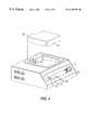
- FIG. 4is a diagrammatic perspective view of the monitor-defibrillator and patient base station.
- FIG. 5is a block diagram for the patient base station patient interface module.
- FIG. 6is a simplified diagrammatic perspective view of an alternative embodiment of a monitor defibrillator, battery pack and battery recharger.
- FIG. 7is a simplified diagram illustrating a presently preferred alternative embodiment of a monitor-defibrillator.
- FIG. 8is a flow diagram illustrating a presently preferred initialization method.
- FIG. 9is a flow diagram illustrating a presently preferred battery operation method.
- FIG. 1An apparatus is provided for monitoring and supporting the monitor-defibrillator electronics and the rechargeable battery pack provided therein.
- the system 10 of the present inventionis shown schematically in FIG. 1 .
- the present system 10involves a number of interrelated components.
- a monitor-defibrillator 12is included which is operatively connectable via an interface module 26 , to either a patient base station 30 or an electrode harness 66 having two groups of electrodes 14 , 16 .
- a group of delivering electrodes 14is provided for delivering a cardioverting or defibrillating shock when necessary to a patient.
- Another group of electrodes 16performs sensing operations in which the physiological condition of a patient may be monitored.
- the delivering electrodes 14are operatively connected to a converter-defibrillator 19 located within the monitor-defibrillator 12 .
- the electrode harness 66also includes a patient display 24 with the capability of displaying visual messages, enunciating audio messages and activating audio alarms.
- the patient display 24also includes various buttons for providing the patient with a means of input to the device.
- the operation of the electrode harness/monitor-defibrillatorare more particularly described in co-pending application Ser. No. 08/651,274, assigned to the present assignee and hereby incorporated by reference herein.
- the battery pack 18is responsible for providing the necessary power to operate the converter-defibrillator circuitry for delivering the cardioverting or defibrillating shock. Therefore, it is important that the energy capacity of battery 18 be ensured.
- the monitor-defibrillator 12preferably utilizes a high-energy-density nickel-cadmium battery. Preferably, the battery is comprised of five 1.2 volt cells connected in series to yield six volts.
- the monitor-defibrillator 12also includes battery control circuitry 20 which can activate the battery 18 to deliver its charge to the converter-defibrillator 19 and subsequently to the delivery electrodes 14 when necessary.
- the battery control circuitry 20is responsive to certain data conditions of the patient. For this reason, the battery control 20 is operatively connected to data storage/processor 22 , also located within the monitor-defibrillator 12 .
- the data storage/processor 22receives data from the sensing electrodes 16 .
- the data storage/processor 22 in the monitor-defibrillatorpreferably utilizes non-volatile memory.
- the data storage/processor 22stores programmable system operational parameters, system operating status information, digitized ECG episodes and the results of hardware diagnostic tests. This data, through subsequent analysis, provides the means to allow reconstruction of ECG events and analysis of device performance.
- the monitor-defibrillator 12is able to perform various system and battery checks. Energy usage of the monitor-defibrillator 12 is monitored in real time to determine the useful energy remaining of the battery 18 per charge.
- the patient display 24 located on the electrode harness 66indicates the operating time remaining for the battery 18 . The patient may access this function at any time by pressing a button on the patient display 24 .
- the run-time parameteris available to an external host via the communications interface located in the interface module 26 .
- a low battery condition as determined by the monitor-defibrillator 12is recorded in non-volatile memory of the data storage/processor 22 . The patient is also alerted to a low battery condition by the patient display 24 .
- the monitor-defibrillator 12monitors the battery current consumption and, if required, makes an appropriate adjustment to the battery run-time parameter based on sampling the real-time monitor-defibrillator current consumption.
- the currentis monitored by an analog circuit in the monitor-defibrillator 12 and is input into a comparator at a trip level of current.
- the voltageis monitored but is not sent to the comparator.
- the trip levelis a level of current that is based on a precalculated worst case (i.e., maximum) average current developed for the device. For the particular hardware used with the present invention, the amount of typical maximum run current (i.e., the trip level current) is 74 milliamps.
- the comparatortrips and the analog to digital converter in the data storage/processor 22 is commanded to read the analog representation of the current that is being drawn by the monitor-defibrillator 12 .
- the monitor-defibrillator 12measures the time period of excessive current draw and the amount of current above the trip level. Based on the measured readings, time is deducted from the battery runtime parameter by the monitor-defibrillator. The updated runtime remaining may be accessed by the patient at any time, as discussed above.
- the data storage/processor 22presumes that the actual current is the same as the trip current when deducting time from the battery runtime parameter.
- the typical maximum run currentis provided as 74 mils, the battery 18 is nearly always providing a current below 74 milliamps.
- the patienthas the capability to access buttons on the patient display 24 that when activated will cause the remaining run time to be indicated. If a patient is very active so as to cause one of the sensing electrodes 16 to have fallen off or otherwise become disconnected from the patient, an alarm is sounded. The activation of this alarm also utilizes energy which will be subtracted from the run time.
- the current measuring capability of the monitor-defibrillator 12does not include current drawn by the converter-defibrillator 19 .
- the monitor-defibrillator 12tracks the periods when the converter-defibrillator 19 is actively drawing current from the battery 18 and makes adjustments to the battery run time to compensate for the energy loss.
- the monitor-defibrillator 12also makes adjustments for depletion of battery 18 capacity during periods when the device is not being used. When not in use (such as when stored on a shelf or taken by the patient on a day's outing as a spare device) the monitor-defibrillator 12 will automatically power itself up at specified intervals and make adjustments to the battery run time to compensate for energy losses due to self-discharge of the battery and current draw of monitor-defibrillator 12 components when powered down.
- the monitor-defibrillator 12will utilize measures intended to reduce depletion of battery 18 capacity in order to maximize available energy if a treatment pulse is required.
- the monitor-defibrillator 12will be optimized to execute its monitoring functions as rapidly as possible and then enter a low power operating mode until the monitoring functions must again be executed.
- the monitor-defibrillatorcan be kept in a low power operating mode when not performing necessary system operating functions. Additionally, when possible, high current devices will be powered down after completing their required tasks.
- An examplewould be the analog to digital converter. By scheduling analog to digital conversion readings at the beginning of monitoring functions, the analog to digital converter can be powered down sooner than if analog to digital readings are interspersed throughout the monitoring functions.
- the patient display 24will provide notification.
- the notificationwill consist of visual and/or audio indicators.
- the notificationwill require acknowledgment by the patient before it will be discontinued.
- the notificationwill be repeated at predetermined intervals, for example, every 15 minutes, until the battery 18 is recharged by the patient base station 30 .
- the monitor-defibrillator 12can also determine the available device operating time (prior to recharging the battery), taking into account at least: (1) adjustments for abnormally high current draw of the device including adjustments for converter operation or operation of other high current draw devices as well as adjustments for excessive current draw from a defective component; (2) adjustments for normal current draw during an elapsed time period; (3) adjustments for device fault conditions such as failure of a battery load test or a problem with operation of the converter; and (4) adjustments for depletion of battery capacity during periods of non-use.
- the patient display 24 or alarmscan be used to notify the patient of the available device operating time.
- the monitor-defibrillator 12will also utilize an analog to digital converter located in the data storage/processor 22 to supervise the battery 18 voltage during operation of the converter-defibrillator 19 .
- the converter-defibrillator 19may be operated in either a fast charge mode or a slow charge mode.
- the fast charge modeminimizes the time to charge the converter-defibrillator 19 but at a maximized current draw from the battery 18 .
- the slow charge modeminimizes the capacitor charging current but with an increased time to charge the converter-defibrillator 19 .
- the converter-defibrillator 19is normally operated in fast charge mode.
- the monitor-defibrillator 12will switch the converter-defibrillator 19 to a slow charge mode. This will permit the battery 18 voltage level to recover to a level at which the monitor-defibrillator 12 can again reliably operate the converter-defibrillator 19 .
- Use of the slow charge modepermits the converter to be operated and a therapy pulse delivered to the patient when the battery 18 capacity is low.
- the monitor-defibrillator 12will deactivate the converter and evaluate the energy capability stored in the converter. If the energy stored in the converter is sufficient to deliver at least a minimal energy pulse, such as, for example, 30 joules, then the treatment cycle will continue with delivery of the available energy. If there is not enough energy stored in the converter to deliver a minimal energy pulse, then the converter will be discharged. In addition, notification will be given using the patient display 24 that the device is disabled and medical assistance should be provided to the patient.
- the monitor-defibrillator 12determines that the battery 18 capacity has fallen below a level at which the system performance data is in danger of being corrupted then the monitor-defibrillator 12 will remove operating power. The removal of operating power will reserve the remaining battery 18 capacity for maintenance of the data storage/processor 22 .
- the integrity of the data storageis essential to evaluating the proper operation of the device. Since this low level of battery 18 capacity is inadequate for reliable operation of the monitor-defibrillator, the best possible use of the remaining battery 18 capacity is to preserve the operational history of the device stored in the data storage/processor 22 .
- the monitor-defibrillatorwill refuse to power up until connected to the patient base station 30 . If required, the patient base station 30 will provide additional energy to the monitor-defibrillator 12 to insure proper functioning during this power up sequence. The patient base station will then retrieve the operational history from the monitor-defibrillator 12 and recharge the battery 18 .
- the analog to digital converter located in the data storage/processor 22is powered up each interim cycle to sample the analog inputs. This interim cycle is preferably every 5 milliseconds, which generally corresponds to the ECG sampling rate. After sampling the analog inputs, the analog to digital converter is powered down to conserve battery power. There are entire portions of the monitor-defibrillator 12 that periodically go into a low current sleep mode.
- the patientis required to couple the monitor-defibrillator 12 with the patient base station 30 (see FIG. 4 ).
- the monitor-defibrillator 12is removed from the electrode harness 66 and inserted in the receptacle 31 of the patient base station, connection is made between the monitor-defibrillator interface 26 and a monitor-defibrillator interface 32 located within the patient base station 30 .
- the patient base station monitor-defibrillator interface 32is thus operatively connected to the data storage/processor 22 of the monitor-defibrillator 12 .
- the monitor-defibrillator interface 32can download information from the memory of the data storage/processor circuitry 22 ; i.e., information, that was received from both the sensing electrodes 16 regarding the patient's physiological data, and also from the battery control circuitry 20 regarding the operating history of the monitor-defibrillator 12 .
- the monitor-defibrillator interface 32 of the patient base station 30is also operatively connected to the battery 18 . In this way, the patient base station 30 can perform comprehensive tests as to the operating parameters of the battery 18 . Further, charging of the battery 18 can also be performed through the monitor-defibrillator interface 32 .
- the battery 18 of each monitor-defibrillator 12requires periodic charging. Thus, monitor-defibrillators 12 that are not in use are to be stored on a patient base station charging port (i.e., coupled to the monitor-defibrillator interface 32 ), where they undergo charging and maintenance operations.
- the patient base station 30provides battery status information to the patient by way of a visual display including indicator lights as well as by audio alarms provided by the patient interface 46 .
- the power required to charge the battery 18 of the monitor-defibrillator 12is supplied by either an internal or an external power supply. As shown in FIG. 1, an internal power supply 38 may be used which is operatively connected to the charger interface module 34 .
- a switch mode type power supply 38is preferred. However, a linear type power supply 38 could also be utilized. If a linear type power supply 38 is used, a heat sink and a fan would be needed in the patient base station 30 . Use of a switch mode type power supply 38 would eliminate the fan, reduce the size of the heat sinks and would reduce the size of the system package and is thus preferred.
- the power supply 38utilizes a power entry module 36 .
- the power entry module 36provides a standard IEC 320 type power entry connector.
- the power entry module 36functions over a full range of standard household international voltages and frequencies.
- the power entry module 36shall preferably use a standard international “1/0” icon for power status indication.
- the monitor-defibrillator interface 32is operatively connected to the charger interface module 34 within the patient base station 30 .
- the charger interface module 34provides a standard PC-AT compatible ISA type interface and provides all the necessary bus signals for computer control of the various charger interface module functions.
- data received by the monitor-defibrillator interface 32 from the data storage/processor 22 of the monitor-defibrillator 12is provided to a computer 40 .
- communicationis then established for transfer of operational data to the patient base station mass data storage area 42 .
- This datais a record of device performance and any ECG data that may have been stored within the monitor-defibrillator 12 during patient monitoring.
- the patient base stationinitiates data retrieval operations from the monitor-defibrillator 12 if operational or ECG data is stored within the internal memory included in the data storage/processor 22 of the monitor-defibrillator 12 .
- this datais transferred to the patient base station 30 for long-term data storage 42 .
- the patient base station 30may store retrieved data on a removable floppy disk, removable or fixed hard disk or other removable media. In the preferred embodiment, the data is stored on a fixed hard disk.
- the computer 40 of the patient base station 30issues a clear memory command via the monitor-defibrillator interface 32 to the monitor-defibrillator 12 . This command erases the temporary memory in the data storage/processor 22 in the monitor-defibrillator 12 .
- the patient base stationnotifies the patient when the removable media requires replacement due to inadequate storage area remaining.
- the computer 40 utilized by the patient base station 30incorporates an imbedded, PC-AT-compatible computer architecture.
- the computer 40preferably utilizes an IntelTM 80 ⁇ 86 type central processing unit, with a performance no less than that of a 25 MHz 80386SX IntelTM processor.
- the computer 40preferably includes two standard PC-AT type serial ports.
- a modem interface port 44should also be available for connecting the computer 40 to a telephone modem (not shown).
- the modem interface 44is designed to interface to a telephone modem with no less than 14.4 kpbs data rate capability.
- the modempreferably interfaces to the single board computer 40 via one of its serial ports.
- a physician's programming console (“PPC”) interface 48provides a communication link from the patient base station (“PBS”) 30 to a physician's programming console 70 .
- the physician's programming console interface 48contains an ethernet communications module 52 for providing a standard 10 Mbps data link to the physician's programming console 70 .
- This module 52preferably interfaces to the single board computer 40 via an expansion bus 54 .
- Data transfers between the patient base station 30 and the physician's programming console 70are handled via the ethernet port 52 . This allows the significant amount of data generated by the monitor-defibrillator 12 to be offloaded in a reasonable time at the physician's office during the patient's periodic visits.
- the external panel connection for the high speed physician's programming console 70 data linkcan use a standard BNC type female connector.
- a serial communications port 50is also part of the physician programming console interface 48 and is provided for connection of the computer 40 to the physician's programming console 70 .
- Data transfer from the patient base station 30 to the physician's programming console 70can also occur via high speed modem interface 44 from the patient's home.
- the computer 40is operatively connected to an ISA type expansion bus 54 .
- the expansion bus 54is designed to be capable of supporting up to four 16 bit expansion modules or cards.
- the computer 40utilizes the expansion bus 54 to facilitate communications, control and status transfers to and from the charger interface module 34 and ethernet communication module 52 of the physicians programming console interface 48 .
- the expansion bus 54also provides power to the computer 40 and the ethernet communication module 52 from the charger interface module 34 .
- the operating system and applications software for the patient base station 30may be stored on rotating media in the mass data storage area 42 .
- the preferred embodimentembeds this software in non-volatile read only memory, such as EEPROM or FLASH memory. These embodiments allow the device to operate without need of rotating media.
- Additional non-volatile memoryis provided to store certain manufacturing information and device-specific data. These memory locations are written to only during the initial manufacturing processes and are then write inhibited by hardware means.
- a real time clockmay be implemented in conjunction with the computer 40 to maintain date and time of day information.
- the clockhas backup power 62 provided to maintain operation if power is removed from the patient base station.
- a counter-timer 72is provided to coordinate time critical operations.
- An analog to digital converter 64is also provided.
- the patient base station computer 40controls battery charging, both rapid charging and float charging once the fill charge point is reached.
- the computer 40also controls discharging of the battery 18 , as required.
- a battery capacity testis periodically performed to verify the stored energy capacity of the monitor-defibrillator battery pack 18 .
- the system processor 40controls all battery capacity measurement operations by discharging the battery 18 to a defined starting level, rapid-charging the battery 18 to full potential, implementing a timed discharge cycle to deplete the battery 18 and calculating the actual energy capacity. This process can determine if a bad cell is present in the battery pack, or the measured battery capacity is less than a defined acceptable limit.
- the patient interface module 46can have a visual display 47 , battery status LED indicators 51 , acknowledge push button 57 and ambient light sensor 49 .
- the patient interface module 46can be operatively associated with the charger interface module 34 and the analog to digital converter 64 .
- the analog to digital converter 64 with an analog multiplexeris preferably provided within the patient base station 30 .
- This analog to digital converter 64allows the single board computer 40 (FIG. 1) to monitor the charging current of the charger/discharger 34 , discharging current of the charger/discharger 34 , the battery voltage present at the monitor-defibrillator interface 32 , the ambient light sensor 49 of the patient interface module 46 and the ambient temperature within the patient base station 30 enclosure via a temperature sensor 55 (shown in FIG. 2 ).
- the patient interface 46 in the patient base station 30indicates the status of the monitor-defibrillator battery 18 during the battery capacity test cycle.
- the patient interface 46preferably incorporates a front panel mounted vacuum fluorescent (VF) type display 47 (shown in FIG. 4 ).
- This display 47may be a character type with standard 5 mm, 5 ⁇ 7 dot characters.
- the PBS display 47is preferably arranged in one of the following configurations: a 2 line by 40 character or a 4 line by 20 character.
- the PBS display 47is controlled by the single board computer 40 via the charger interface module 34 through a parallel data interface.
- a graphics type LCDmay be used for the PBS display 47 . If an LCD display is used, the patient base station may include an ambient light sensor 49 to control the LCD backlight for improved readability.
- the patient base station 30tracks battery 18 usage and notifies the patient when replacement of the battery 18 is required. If the battery 18 expiration parameters have been exceeded (the expiration date or the number of charge cycles), the battery 18 can still be used by the monitor-defibrillator 12 , but the patient will be notified to replace the monitor-defibrillator 12 as soon as possible. The number of charging cycles performed on the battery 18 is recorded in the monitor-defibrillator memory of the data storage/processor 22 .
- monitor-defibrillator data storage/processor 22the date the battery 18 was installed in the monitor-defibrillator 12 , the type of cell used in the battery 18 , and the expiration date of the battery 18 as well as any other pertinent information is stored in monitor-defibrillator data storage/processor 22 .
- the communications interface created when the patient base station 30 and attached monitor-defibrillator 12 is connected to the physician's programming console 70is utilized during the initial configuration programming of the monitor-defibrillator 12 .
- the following informationis configured: name, address, telephone number, hospital, attending physician, medications; monitor-defibrillator detection and treatment parameters such as heart rate threshold or rate cutoff, defibrillation energy to be delivered in therapy pulses; and monitor-defibrillator manufacturing data such as device serial numbers, monitor-defibrillator battery pack. and expiration date, electrode harness(s) and expiration date(s).
- a data communications protocolfacilitates the transfer of digital information between the patient base station 30 and the physician's programming console 70 .
- This protocolconsists of transferring data in blocks or frames. To ensure the integrity of transmitted and received data, the protocol implements error checking techniques.
- the patient base station 30 to physician's programming console 70 communications protocolconsists of transferring data in frames. Communication frames are transferred via the serial communication port 50 . Serial communication port 50 hardware control lines are utilized to provide handshaking between the patient base station 30 and the physician's programming console 70 that will delimit the frame boundaries.
- Each communication cycleconsists of a command frame sent from the physician's programming console 70 to the patient base station 30 , followed by a response frame sent from the patient base station 30 to the physician's programming console 70 .
- Each command framewill contain a command code followed by any relevant data, followed by an error checking code such as a CRC code.
- the patient base station 30will return a response frame that contains an ACK code, followed by the original received command code, followed by any relevant data, followed by an error checking code such as a CRC code.
- the patient base station 30will return a response frame that contains a NAK code, followed by the original received command code, followed by any relevant data, followed by an error checking code such as a CRC code.
- the patient base station 30will ignore the communication frame.
- the physician's programming console 70will be responsible for monitoring the patient base station 30 response. If the patient base station 30 does not respond to a command frame the physician's programming console 70 can elect to resend the frame.
- the physician's programming console 70can elect to resend the frame.
- Another data communications protocolfacilitates the transfer of digital information between the monitor-defibrillator 12 and the patient base station 30 .
- the protocolconsists of transferring data in blocks or frames.
- the patient base station (“PBS”) 30 to monitor- defibrillator (“M-D”) 12 communications protocolconsists of transferring data in frames. Communication frames are transferred via the PBS/M-D interface 32 . PBS/M-D interface 32 hardware control lines are utilized to provide handshaking between the patient base station 30 and the monitor-defibrillator 12 that will delimit communication frame boundaries.
- Each communication cycleconsists of a command frame sent from the patient base station 30 to the monitor-defibrillator 12 , followed by a response frame sent from the monitor-defibrillator 12 to the patient base station 30 .
- Each command framewill contain a command code followed by any relevant data, followed by an error checking code such as a CRC code.
- the monitor-defibrillator 12will return a response frame that contains an ACK code, followed by the original received command code, followed by any relevant data, followed by an error checking code such as a CRC code.
- the monitor-defibrillator 12will return a response frame that contains a NAK code, followed by the original received command code, followed by any relevant data, followed by an error checking code such as a CRC code.
- the patient base station 30will determine and execute a response appropriate for the failed monitor-defibrillator 12 command process.
- the monitor-defibrillator 12If a command frame is received by the monitor-defibrillator 12 that contains an invalid error checking code, the monitor-defibrillator 12 will return a response frame that contains a code indicating that the command was not properly received and should be resent.
- the patient base station 30can elect to resend the command frame.
- the patient base station 30can elect to resend the frame or initiate monitor-defibrillator 12 fault condition processing.
- the patient base station 30offers a collection of commands that the physician's programming console 70 can utilize during communications with the patient base station 30 .
- the command setprovides a means to initiate various patient base station 30 and monitor-defibrillator 12 diagnostic, configuration, and data retrieval procedures.
- the physician's programming console 70can gain access to various monitor-defibrillator 12 information and operational features by issuing commands to the patient base station 30 via the serial communications port 50 . Upon receipt of these commands, the patient base station 30 will issue the appropriate commands to the monitor-defibrillator 12 via the PBS/ M-D interface 32 , that will carry out the desired operation. The patient base station 30 will return to the physician's programming console 70 the monitor-defibrillator 12 response to the operation.
- a digital output from the monitor-defibrillator data storage/processoris provided to control the activation of the battery test load. Activation of the load places a high current demand on the monitor-defibrillator battery 18 . This determines if the monitor-defibrillator battery pack contains any defective cells.
- the monitor-defibrillator 12can determine the available device operation time (prior to recharging the battery) utilizing adjustments for abnormally high current draw, normal current draw, device fault conditions, and depletion of battery capacity during periods when the device is not in use.
- the monitor-defibrillator 12Upon command from the patient base station or the monitor-defibrillator display, the monitor-defibrillator 12 performs a battery load test. The monitor-defibrillator 12 returns a pass-fail indication to the patient base station or the display. Load tests are most often performed with the display as the host. If the battery 18 fails the load test, the battery voltage measurement prior to the load test and at the point of failure are stored in the monitor-defibrillator non-volatile memory.
- the patient base station 30provides circuitry in the charger interface module 34 , that can charge or discharge the monitor-defibrillator 12 battery pack 18 .
- the charger interface module 34connects to the monitor-defibrillator 12 battery pack 18 via the PBS/M-D interface 32 .
- the patient base station 30will retrieve battery pack 18 identification information from the monitor-defibrillator 12 via the PBS/M-D interface 32 .
- Two charging modesare provided; rapid charging and float charging.
- the charger interface module 34supplies charging current at the one hour charge rate of the battery pack 18 .
- the charger interface module 34supplies charging current at the continuous maintenance rate of the battery pack 18 .
- the rapid and float charge current rates supplied by the charger interface module 34are adjustable by the patient base station computer 40 .
- the patient base station computer 40will configure the charger interface module 34 to supply a charge current rate that is appropriate for the connected battery pack 18 .
- the charger interface module 34provides a resistive load to the battery pack 18 that discharges the battery pack 18 at the one hour discharge rate of the battery pack 18 .
- the discharge resistive load applied by the charger interface module 34is adjustable by the patient base station computer 40 .
- the patient base station computer 40will configure the charger interface module 34 to apply a resistive load that causes a one hour current drain rate that is appropriate for the connected battery pack 18 .
- the battery charger interface module 34can be controlled by the patient base station computer 40 or by the monitor-defibrillator 12 via the PBS/M-D interface 32 .
- Monitor-defibrillator 12 control of the charger interface module 34is accomplished by activating I/O control lines located in the PBS/M-D interface 32 . These I/O lines will configure the charger interface module 34 for the desired charge/discharge operation.
- the patient base station computer 40can control the I/O lines and configure the charger interface module 34 for the desired charge/discharge operation.
- the monitor-defibrillator 12controls the configuration of the charger interface module 34 .
- the patient base station 30 configuration of the charger interface module 34is a redundant feature that can be utilized if certain monitor-defibrillator 12 fault conditions exist such as a totally discharged monitor-defibrillator 12 battery pack 18 .
- Battery pack 18 charge and discharge cyclesare initiated by the patient base station computer 40 .
- the patient base station 30retrieves monitor-defibrillator 12 battery operational status data from the data storage/processor 22 via PBS/M-D interface 32 .
- the retrieved battery operational status dataincludes information such as the remaining battery capacity, fault condition flags, expiration parameters, battery maintenance parameters, and battery identification information.
- the patient base station 30analyzes the retrieved battery data to determine the appropriate battery pack 18 maintenance procedure.
- a command to initiate a rapid charge cyclewill be sent to the monitor-defibrillator 12 via the PBS/M-D interface 32 .
- the monitor-defibrillator 12Upon receipt of this command, the monitor-defibrillator 12 will configure the charger interface module 34 for rapid charge operation by activating I/O control lines located in the PBS/M-D interface 32 .
- the monitor-defibrillator 12will monitor the rapid charge sequence for completion and fault conditions. Successful rapid charge completion is determined by the monitor-defibrillator 12 monitoring the voltage level at the battery pack 18 positive terminal via the A/D converter located in the data storage/processor module 22 .
- Successful rapid charge completioncan also be declared if the monitor-defibrillator 12 detects a defined change in battery pack 18 temperature.
- the monitor-defibrillator 12monitors the battery temperature via a temperature sensor located in the battery pack 18 and the A/D converter located in the data storage/processor module 22 .
- the monitor-defibrillator 12will configure the charger interface module 34 for float charge operation by activating I/O control lines located in the PBS/M-D interface 32 , reset the monitor-defibrillator 12 runtime parameter to the maximum value, and issue a rapid charge complete communications frame to the patient base station 30 via the PBS/M-D interface 32 .
- the rapid charge cyclewill be aborted if the monitor-defibrillator 12 detects one of the following conditions: a battery pack 18 over voltage condition; a battery pack 18 over temperature condition; or a defined time interval elapsed without a rapid charge completion detected.
- the limit valuesare manufacturing parameters that are stored in the monitor-defibrillator 12 data storage/processor module 22 .
- the monitor-defibrillator 12will configure the charger interface module 34 for float charge operation by activating I/O control lines located in the PBS/M-D interface 32 ; the monitor-defibrillator 12 will set it's runtime parameter to zero, which will cause patient warning messages on the display 24 ; and the monitor-defibrillator 12 will issue a rapid charge fault communications frame to the patient base station 30 via the PBS/M-D interface 32 .
- the patient base station 30receives a rapid charge fault communications frame from the monitor-defibrillator 12 , the following operations will be performed: the event will be logged in the patient base station 30 operations log file located in the data storage module 42 ; and the patient base station 30 will activate a patient warning message that indicates the monitor-defibrillator 12 should be serviced.
- the patient base station 30will insure proper charge operation by monitoring various system parameters.
- the system parameter limit valuesare stored in the data storage module 42 during the patient base station 30 manufacturing process.
- the charging current supplied to the battery pack 18is monitored for proper levels via an A/D converter 64 (FIG. 5) channel connected to the charger interface module 34 . If the measured current is outside the defined limits, the patient base station 30 will abort the rapid charge cycle.
- the charging voltage on the battery pack 18is monitored for proper levels via an A/D converter 64 channel connected to the charger interface module 34 . If the measured voltage is outside the defined limits, the patient base station 30 will abort the rapid charge cycle.
- the patient base station 30will abort the rapid charge cycle if the counter timer 72 (FIG. 2) indicates the charge cycle exceeded the maximum charge completion interval.
- an abort rapid charge cycle commandwill be issued to the monitor-defibrillator 12 via the PBS/M-D interface 32 ; the patient base station 30 will configure the charger interface module 34 for float charge operation; the patient base station 30 will issue a command to the monitor-defibrillator 12 to set the runtime parameter to zero, which will cause patient warning messages on the display 24 ; the event will be logged in the patient base station 30 operations log file located in the data storage module 42 ; and the patient base station 30 will activate a patient warning message that indicates the monitor-defibrillator 12 should be serviced.
- the patient base station 30may initiate a discharge cycle of the monitor-defibrillator 12 battery pack 18 .
- the discharge cycleis utilized both during the battery capacity test as well as during the process of reconditioning the battery energy storage capabilities.
- a command to initiate a discharge cyclewill be sent to the monitor-defibrillator 12 via the PBS/M-D interface 32 .
- the monitor-defibrillator 12Upon receipt of this command the monitor-defibrillator 12 will set the monitor-defibrillator 12 runtime parameter to zero and configure the charger interface module 34 for discharge operation by activating I/O control lines located in the PBS/M-D interface 32 .
- the monitor-defibrillator 12will monitor the discharge sequence for completion and fault conditions. Successful discharge completion is determined by the monitor-defibrillator 12 detecting the defined final discharge voltage threshold on the battery pack 18 positive terminal via the A/D converter located in the data storage/processor module 22 .
- the monitor-defibrillator 12When the monitor-defibrillator 12 detects a successful discharge completion, the monitor-defibrillator 12 will configure the charger interface module 34 for float charge operation, by activating I/O control lines located in the PBS/M-D interface 32 , and issue a discharge complete communications frame to the patient base station 30 via the PBS/M-D interface 32 .
- the discharge cyclewill be aborted if the monitor-defibrillator 12 detects one of the following conditions: a battery pack 18 over temperature condition; or a defined time interval has elapsed without the detection of the discharge complete condition.
- the limit valuesare manufacturing parameters that are stored in the monitor-defibrillator 12 data storage/processor module 22 .
- the monitor-defibrillator 12will configure the charger interface module 34 for float charge operation by activating I/O control lines located in the PBS/M-D interface 32 ; and the monitor-defibrillator 12 will issue a discharge fault communications frame to the patient base station 30 via the PBS/M-D interface 32 . If the patient base station 30 receives a discharge fault communications frame from the monitor-defibrillator 12 , the event will be logged in the patient base station 30 operations log file located in the data storage module 42 and a patient warning message will be activated on the PBS display 47 that indicates the monitor-defibrillator 12 should be serviced.
- the patient base station 30will insure proper discharge operation by monitoring various system parameters.
- the system parameter valuesare stored in the data storage module 42 during the patient base station 30 manufacturing process.
- the discharge current drawn from the battery pack 18is monitored for proper levels via an A/D converter 64 channel connected to the charger interface module 34 . If the measured current is outside the defined limits, the patient base station 30 will abort the discharge cycle.
- the discharge voltage on the battery pack 18is monitored for proper levels via an A/D converter 64 channel connected to the charger interface module 34 . If the measured voltage is outside the defined limits, the patient base station 30 will abort the discharge cycle.
- the patient base station 30will abort the discharge cycle if the counter timer 72 indicates the discharge cycle exceeded the maximum discharge completion interval.
- an abort discharge cycle commandwill be issued to the monitor-defibrillator 12 via the PBS/M-D interface 32 ; the patient base station 30 will configure the charger interface module 34 for float charge operation; the patient base station 30 will issue a command to the monitor-defibrillator 12 to set the runtime parameter to zero, which will cause patient warning messages on the display 24 ; the event will be logged in the patient base station 30 operations log file located in the data storage module 42 ; and the patient base station 30 will activate a patient warning message that indicates the monitor-defibrillator 12 should be serviced.
- the rapid charge cycle or discharge cyclewill not be initiated if the monitor-defibrillator 12 determines that the battery pack 18 temperature is outside a set of defined limits.
- the limit valuesare manufacturing parameters that are stored i n the monitor-defibrillator 12 data storage/processor module 22 .
- monitor-defibrillator 12If the monitor-defibrillator 12 is removed from the patient base station 30 prior to completion of all battery pack maintenance operations, a message and alarm will be activated on the patient interface module 46 . The message will indicate the monitor-defibrillator maintenance is not complete and to return the monitor-defibrillator to the patient base station. The interrupted maintenance procedure will be continued if the removed monitor-defibrillator 12 is reconnected to the patient base station 30 .
- the energy delivery capabilities of the battery pack 18are periodically verified by testing the battery 18 energy capacity and high current delivery capabilities.
- the patient base station 30will perform an energy capacity test on the battery pack 18 if the elapsed time from the last capacity test, as indicated by data retrieved from monitor-defibrillator data storage/processor module 22 via the PBS/M-D interface 32 , exceeds the maximum time interval parameter stored in the data storage module 42 , or status data retrieved from monitor-defibrillator data storage/processor module 22 via the PBS/M-D interface 32 , indicates that the battery 18 operational performance was deficient during the previous patient monitoring cycle.
- the battery 18 energy capacity test procedureconsists of the following operations: the patient base station 30 will activate a message on the patient interface 46 visual display 47 that indicates the monitor-defibrillator 12 is being tested and to wait for the test to complete; the patient base station 30 initiates a battery discharge cycle to condition the battery for a full charge cycle; initiate a rapid charge cycle when the discharge cycle is complete to charge the battery 18 to full capacity; the patient base station 30 initiates a second discharge cycle when the rapid charge cycle is complete; and the patient base station 30 initiates a final rapid charge cycle at the completion of the second discharge cycle to ready the battery 18 for service.
- the duration of the second discharge cycleis timed by a counter timer located in the monitor-defibrillator 12 data storage/processor module 22 .
- monitor-defibrillator 12will compare the measured battery 18 discharge time with an acceptance parameter stored in storage/processor module 22 . If the capacity discharge time is within the acceptable limit, monitor-defibrillator 12 will issue a capacity discharge pass communications frame to the patient base station 30 via the PBS/M-D interface 32 .
- the monitor-defibrillator 12will set a battery capacity fault status flag located in the data storage/processor module 22 , and issue a capacity discharge fault communications frame to the patient base station 30 via the PBS/M-D interface 32 .
- the patient base station 30will log the event in a log file located in the data storage module 42 .
- a patient warning messagewill be activated which indicates that the monitor-defibrillator 12 should be serviced as soon as possible.
- the patient base station 30Each time a monitor-defibrillator 12 is connected to the patient base station 30 , the patient base station 30 will retrieve the monitor-defibrillator 12 battery capacity fault status flag located in the data storage/processor module 22 . If the battery capacity fault status flag is active, the patient base station 30 will initiate normal battery maintenance operations, with the exception of the battery capacity test which will no longer be performed. The patient base station 30 will also issue a command to the monitor-defibrillator 12 to set the runtime parameter to zero. This will cause repeated patient warning messages on the patient display 24 .
- the patientwill be notified by the patient base station 30 that the monitor-defibrillator 12 should be serviced.
- the notification sequencewill be activated until the patient acknowledges receipt by pressing a button 57 (FIG. 4) on the patient interface 46 , or the monitor-defibrillator 12 is removed from the patient base station 30 . Normal battery maintenance will continue so that the patient may use the monitor-defibrillator 12 .
- the patient base station 30When a rapid charge cycle or battery discharge cycle is initiated, the patient base station 30 will deactivate the particular one of the battery status LED indicators 51 which is the “READY” LED indicator on the patient interface module 46 and activate the particular one of the battery status LED indicators 51 which is the “CHARGING” LED indicator. During the rapid charge cycle, the patient base station 30 displays a message on the patient interface visual display 47 that the monitor-defibrillator battery 18 is being charged and the monitor-defibrillator 12 is not ready for use.
- the patient base stationperforms the following:
- a messageis displayed on the PBS display 47 indicating that the monitor-defibrillator 12 is ready for use; the PBS 30 “READY” LED 51 is activated; the “CHARGING” LED 51 is deactivated; and the monitor-defibrillator 12 is powered down.
- the patient base station 30logs the following battery maintenance information into a maintenance log: the start and completion times of battery operations; the length of the charge/discharge cycles; any abnormal conditions; and the charge cycle count, and if enabled, the battery voltage measurements taken during charge and discharge cycles.
- the maintenance logis stored in the data storage module 42 .
- the patient base station 30issues various diagnostic test commands to the monitor-defibrillator 12 . These tests are performed on a regular basis. Some tests are performed each time the monitor-defibrillator 12 is connected to the patient base station 30 . Others are performed only as required.
- the monitor-defibrillator 12executes the received commands and reports the test results to the patient base station 30 .
- the patient base station 30maintains a log of the test results on the mass storage media 42 . If a fault is detected during any diagnostic procedure, the patient is notified of the condition along with the appropriate corrective action.
- the preferred patient base station 30utilizes a charger interface module board. Stacked on top of that board are purchased assemblies of PC104 boards which form the CPU module 40 and Ethernet module 52 . These boards are ISA compatible because the expansion bus 54 is an ISA type bus. The stacks of PC104 boards require a great deal of cabling which is very costly. Thus, all of the major system functions could be implemented on a single PC board. This would eliminate much of the cabling.
- FIG. 6a basic perspective view of an alternative embodiment of a battery management system 110 is shown having a monitor defibrillator 112 , rechargeable battery pack 118 and battery pack recharger 190 .
- a battery pack receptacle 182is provided in the monitor-defibrillator 112 wherein the battery pack 118 is adapted to be received for use as a power supply.
- the recharger 190includes a battery pack receptacle 184 to receive the battery pack 118 for recharging and, if desired, testing to determine the operational condition of the battery pack 118 .
- the battery pack 118 memory/processoris configured to exchange information with both a processor in the recharger 190 and the data storage/processor 22 in the monitor-defibrillator 112 .
- monitor-defibrillator 112As can be seen in the simplified diagram shown in FIG. 7, all of the heretofore described functions carried out by the patient base station 30 , except for the battery recharging and related functions, can be carried out by an upgraded monitor-defibrillator 112 having increased functional capabilities. Basically, the monitor-defibrillator 112 package has been upgraded/expanded to include the circuitry necessary to perform the functions of not only the previously described monitor-defibrillator 12 , but additionally, the functions formerly performed by the patient base station 30 .
- monitor-defibrillator 12 and patient base station 30are eliminated, for example the respective interface modules 26 and 32 , external power supply 60 , power entry module 36 , power supply 38 , computer 40 and battery charger interface module 34 that are not required for the expanded function monitor-defibrillator 112 .
- Some of the componentsare obsoleted by the fact that the monitor-defibrillator 112 no longer interfaces with a base station.
- Other componentssuch as those related to battery recharging will be part of the battery charger 190 to be used with the smart battery pack 118 .
- the monitor-defibrillator 112can include maintenance circuitry for providing an indication of the operation condition of the monitor-defibrillator 112 whereas the battery recharger 190 can include battery maintenance circuitry for providing an indication of the operating condition of the rechargeable battery pack 118 .
- the data storage/processor 22is also a “computer.” However, the functioning of the data storage/processor 22 may also be upgraded with regard to memory and processing capabilities in order to handle the added functionality taken over by the monitor-defibrillator 112 .
- another input/output 170 optionis an infrared communication module 53 , which can be used in addition to the serial port 50 or ethernet module 52 .
- the battery management system 110also contemplates the use of what is known as a “smart battery” pack 118 .
- a smart batteryis a relatively new type of battery which has an internal memory/processor that monitors the condition of the battery and can also communicate with a battery recharger 190 designed to recharge such smart battery packs.
- the pack recharger 190also has a processor to read and update the memory/processor in the smart battery pack 118 .
- the recharger 190can include the battery pack recharging, maintenance and testing functionality previously performed by the patient base station 30 .
- the smart battery pack 118 memory/processorcan communicate with data storage/processor 22 in the monitor-defibrillator 112 .
- a preferred smart battery pack 118 and recharger 190are described in more detail below, in connection with FIGS. 8 and 9.
- the monitor-defibrillator 112performs, in addition to the functions previously described for the monitor-defibrillator 12 , all the functions previously associated with the patient base station 30 , except battery recharging.
- the monitor-defibrillator 112has a receptacle 182 adapted to receive the smart battery pack 118 for use as a power supply, communicates therewith to ascertain the battery condition stored in the memory of the smart battery 118 , performs test operations thereon, and can update the internal memory regarding the battery condition when appropriate.
- Both the battery pack 118 and the battery pack receptacle 182 in the monitor-defibrillator 112are provided with the requisite contacts and interfaces necessary for the monitor-defibrillator to be powered by the battery pack 118 and also for the data storage/processor 22 in the monitor-defibrillator 112 to exchange information with the memory/processor in the smart battery pack 118 .
- the smart battery pack 118is equipped to monitor the battery drain only for the computer circuitry of the monitor-defibrillator 112 , it is not designed to monitor the current drain caused by the high voltage converter.
- the upgraded monitor-defibrillator 112can independently monitor the charge status of the battery.
- This separate energy monitoring functioncan be, for example, provided by an “energy monitoring circuit” 180 which very precisely measures the energy output of the converter-defibrillator circuit 19 , which energy is, of course, provided by the smart battery pack 118 .
- the monitor-defibrillator 112can then update the memory of the smart battery pack 118 with this information to determine the final condition of the battery regarding the available energy.
- the smart battery and recharger hardwarewill supply various diagnostic capabilities to the battery management system.
- the capabilitieswill include providing accurate run-time information to the monitor-defibrillator 112 , storage of fault flag information for both the monitor-defibrillator 112 , and storage of information which allows both the battery charger and monitor-defibrillator 112 to adapt operation to different types of smart batteries.
- FIGS. 8 and 9illustrate certain preferred flow diagrams which can be used as a guide during the design and implementation of both the battery charger 190 and monitor-defibrillator 112 software.
- the determination of available monitor-defibrillator 112 run timeis based upon multiple factors.
- the design of the monitor-defibrillator smart battery pack 118preferably includes a BenchMarqTM Model BQ2092 “gas gauge” integrated circuit.
- the BQ2092continuously monitors the current being consumed by the monitor-defibrillator 112 and adjusts an internal capacity register.
- the monitor-defibrillator 112reads the capacity register to determine available operating time which is displayed to the patient in hours and minutes.
- the smart battery pack 118 internal circuitryhas been designed to particularly monitor the current being drawn by the data storage/processor circuitry of the monitor-defibrillator 112 .
- the monitor-defibrillator 112can have, for example, the aforementioned energy monitoring circuit 180 for precisely measuring this current drain and using this information to make an appropriate adjustment to the smart battery pack 118 gas gauge, based on measuring the operation time of the converter.
- the remaining capacity register of the smart battery pack 118will be adjusted based on a calculation performed by the monitor-defibrillator 112 after operation of the converter.
- the remaining capacity register contained in the BenchMarq BQ2092 ICdoes not provide enough information to accurately determine the remaining run time of the monitor-defibrillator 112 .
- the monitor defibrillator 112 design specificationsindicate that the monitor-defibrillator 112 must be able to operate for a period of 24 hours, and at the end of the 24 hour period, be able to deliver five full energy defibrillation pulses without entering converter foldback mode.
- Converter foldback modeis a mode of converter operation that is enabled if the battery pack terminal voltage falls below a predefined threshold during operation of the converter interface.
- the smart battery pack 118must have sufficient reserve capacity to operate the converter interface while maintaining a battery pack voltage which is above this threshold. Due to the five pulse requirement, the smart battery pack 118 must have additional calibration information stored in the battery pack memory which allows the monitor-defibrillator 112 to verify that sufficient reserve capacity exists in the battery to operate the converter at the 24 hour operating point.
- ReserveCapacityCutoffA reserve battery capacity calibration constant, “ReserveCapacityCutoff,” will be stored in each monitor-defibrillator 112 during manufacturing.
- the value of ReserveCapacityCutoffmust be determined by a battery qualification test which exercises the smart battery pack 118 under simulated current drawings.
- the monitor-defibrillator 112 softwarewill read this constant during initialization and use it to determine run time based on the following formula:
- the constants ReserveCapacityCutoff and SystemCurrentmust be maintained in the monitor-defibrillator 112 data storage/processor 22 .
- the battery pack 118will also maintain a RemainingCapacity (command code 0x0F) register which will be used to determine available operating time and which is adjusted by circuitry internal to the battery pack 118 based on actual sensed battery current drain.
- the monitor-defibrillator 112 softwaregenerally decrements its run time counter in a linear fashion. In one method, adjustments to the run time, outside of a straight decrement in time, will only be made if the above calculation indicates a run time less than the decremented time amount or operation of the high voltage converter occurs time amount or operation of the high voltage converter occurs.
- the monitor-defibrillator 112predicts the amount of operating time remaining based on actual usage.
- the current drain of the systemis measured by hardware/software in the monitor-defibrillator 112 , this is in addition to the smart battery pack 118 , and averaged over a defined interval.
- the monitor-defibrillator 112will calculate the estimated run time amount based on the RemainingCapacity value that is maintained in the smart battery pack 118 and the average current consumption measured by the RemainingCapacity (0x0F) register.
- This run time valueis a more realistic prediction of how long the system will operate based on actual usage.
- the only time the smart battery pack 118 RemainingCapacity register value is adjusted by the monitor-defibrillator 112is during converter operation. If an adjustment becomes necessary, the monitor-defibrillator 112 will modify the battery pack 118 RemainingCapacity (0x0F) register with a new capacity value based on the duration of converter operation.
- the above formulawill be used to initialize the initial run time variable CurrentRuntime.
- the Current/Runtime variableis decremented based on elapsed time after the initial calculation is performed.
- the monitor-defibrillator 112will recalculate the formula and compare the calculated run time to the run time which is being decremented based upon elapsed time. If the new calculated run time indicates less time available than the CurrentRuntime variable, the variable will be set equal to the calculated time. This situation may occur if the patient display is activated for significant periods of time, causing greater than average current drain from the battery.
- the flow diagram shown in FIG. 8illustrates one presently preferred embodiment of software flow during initialization of the monitor-defibrillator 112 when a battery pack 118 is installed.
- the initial calculation of CurrentRuntimeis performed along with a test for charger detected error conditions.
- a status variable, “BatteryErrorStatus,” maintained in the battery packis shared by the monitor-defibrillator 112 and charger.
- Variable BatteryErrorStatuslocated in the battery pack 118 ManufacturerAccess (Command code 0x00) register low byte, is used by the monitor-defibrillator 112 to flag the battery charger 190 to perform a capacity test cycle after certain operating conditions are detected such as converter foldback or a low battery voltage state. Detected error conditions and resulting battery charger 190 operations are described later in this document.
- the battery charger 190can conduct periodic battery capacity measurements and monitor the integrity of the battery pack 118 .
- the battery pack 118 capacity testwill be initiated based on checking an internal battery pack register value, “TestCycleNumber,” that will be stored in the ManufacturerAccess (Command code 0x00) register high byte of the BQ2092.
- Variable TestCycleNumberis reset to zero by the charger 190 whenever a battery capacity test cycle has been completed. This value is maintained and updated by the charger 190 whenever the battery pack 118 completes a charge cycle.
- Manufacturing constant “CyclesPerTestSequence”will be stored in the manufacturing data (command code 0x23) area of the BenchMarq BQ2092 IC. Constant CyclesPerTestSequence will be programmed at the time of manufacturing and will indicate the number of charge cycles between capacity test sequences.
- the charger 190When a smart battery pack 118 is inserted into the charger 190 , the charger 190 will read variables TestCycleNumber and CyclesPerTestSequence and determine if a capacity test cycle is required. Prior to commencement of the capacity test it will be necessary for the charger 190 to determine if the patient's current battery pack 118 is capable of sustaining monitor-defibrillator 112 operations for the duration of the test. The battery charger 190 will not initiate a battery capacity test sequence if the previously charged battery pack 118 has Bit 1 of the BatteryErrorStatus set or does not have sufficient reserve capacity to operate the monitor-defibrillator 112 for the duration of the test.
- the monitor-defibrillator 112may periodically request a battery capacity test via variable BatteryErrorStatus Bit 0 contained in the BenchMarq BQ2092 ManufacturerAccess (Command code 0x00) register low byte.
- BatteryErrorStatus Bit 0contained in the BenchMarq BQ2092 ManufacturerAccess (Command code 0x00) register low byte.
- Bit 0Set by the monitor-defibrillator 112 if converter foldback or low battery voltage condition exists during operation.
- Bit 1Set by battery charger if the smart battery pack 118 fails battery capacity test or the battery pack 118 is otherwise defective.
- the charger 190should proceed to perform a battery capacity test.
- the charger 190must keep track of the time when a fully charged battery pack 118 was removed from the charger 190 and assume that it will power the monitor-defibrillator 112 system for a period of twelve hours.
- the decision to perform the battery capacity testmust take into consideration the actual worst case duration of the test and the remaining run time of the last fully charged battery pack 118 .
- the testshould not be initiated if the battery pack 118 which is currently being used by the patient does not have sufficient reserve capacity to power the monitor-defibrillator 112 for the worse case capacity test time or if the battery pack 118 is faulty (Bit 1 is set).
- the charger 190Upon completion of the capacity test, the charger 190 should compare the measured battery capacity to battery pack 118 parameter LowLimitCapacity which is stored in the manufacturing data area. If the battery pack 118 capacity is less than this value, the charger 190 should clear Bit 0 & set Bit 1 of variable BatteryErrorStatus. If the test passes, then both error Bits should be cleared.
- the flow diagram shown in FIG. 9illustrates one general, presently preferred, method of operation of the battery charger 190 .
- all status illuminatorsshould be turned off.
- the previously defined battery maintenance constantswill be mapped into the manufacturing data area and the variables mapped to the registers of the BQ2092. This section defines the storage locations of the variables and constants in the BQ2092. The variables and constants must be initialized to default values during the battery pack manufacturing process.
- the base addressindicates the first byte of the manufacturing data string provided by BQ2092 function ManufacturingData (command code 0x23).
Landscapes
- Health & Medical Sciences (AREA)
- Engineering & Computer Science (AREA)
- General Health & Medical Sciences (AREA)
- Public Health (AREA)
- Heart & Thoracic Surgery (AREA)
- Biomedical Technology (AREA)
- Nuclear Medicine, Radiotherapy & Molecular Imaging (AREA)
- Radiology & Medical Imaging (AREA)
- Life Sciences & Earth Sciences (AREA)
- Animal Behavior & Ethology (AREA)
- General Physics & Mathematics (AREA)
- Cardiology (AREA)
- Veterinary Medicine (AREA)
- Physics & Mathematics (AREA)
- Power Engineering (AREA)
- Manufacturing & Machinery (AREA)
- Chemical & Material Sciences (AREA)
- Chemical Kinetics & Catalysis (AREA)
- Electrochemistry (AREA)
- General Chemical & Material Sciences (AREA)
- Electrotherapy Devices (AREA)
Abstract
Description
| Constant Name | Size in Bytes | Manufacturing String Index |
| 2 | BASE ADDRESS+0&1 | |
| CyclesPerTestSequence | ||
| Variable Name | Size in Bytes | Register Location in |
| BatteryErrorStatus | ||
| 1 | ManufacturerAccess(0x00) | |
| TestCycleNumber | ||
| 1 | ManufacturerAccess(0x00) High Byte | |
Claims (35)
Priority Applications (3)
| Application Number | Priority Date | Filing Date | Title |
|---|---|---|---|
| US09/361,110US6169387B1 (en) | 1997-12-22 | 1999-07-26 | Battery management apparatus for portable electronic devices |
| CA002311873ACA2311873A1 (en) | 1999-07-26 | 2000-06-15 | Battery management apparatus for portable electronic devices |
| EP00114163AEP1072285A1 (en) | 1999-07-26 | 2000-07-12 | Battery management apparatus for portable electronic devices |
Applications Claiming Priority (2)
| Application Number | Priority Date | Filing Date | Title |
|---|---|---|---|
| US08/995,713US5929601A (en) | 1997-12-22 | 1997-12-22 | Battery management apparatus for portable electronic devices |
| US09/361,110US6169387B1 (en) | 1997-12-22 | 1999-07-26 | Battery management apparatus for portable electronic devices |
Related Parent Applications (1)
| Application Number | Title | Priority Date | Filing Date |
|---|---|---|---|
| US08/995,713Continuation-In-PartUS5929601A (en) | 1997-12-22 | 1997-12-22 | Battery management apparatus for portable electronic devices |
Publications (1)
| Publication Number | Publication Date |
|---|---|
| US6169387B1true US6169387B1 (en) | 2001-01-02 |
Family
ID=23420689
Family Applications (1)
| Application Number | Title | Priority Date | Filing Date |
|---|---|---|---|
| US09/361,110Expired - LifetimeUS6169387B1 (en) | 1997-12-22 | 1999-07-26 | Battery management apparatus for portable electronic devices |
Country Status (3)
| Country | Link |
|---|---|
| US (1) | US6169387B1 (en) |
| EP (1) | EP1072285A1 (en) |
| CA (1) | CA2311873A1 (en) |
Cited By (170)
| Publication number | Priority date | Publication date | Assignee | Title |
|---|---|---|---|---|
| US20020035703A1 (en)* | 2000-09-18 | 2002-03-21 | Yosuke Konaka | Electronic apparatus and processing ability alteration instruction apparatus |
| US6418342B1 (en) | 1997-03-07 | 2002-07-09 | Cardiac Science Inc. | Defibrillation system |
| US6459173B1 (en) | 2000-10-30 | 2002-10-01 | Rockwell Automation Technologies, Inc. | Self-programmable battery load/bias for memory expansion module |
| US20030057918A1 (en)* | 2001-09-19 | 2003-03-27 | International Business Machines Corporation | Electric device with intelligent battery system therein |
| US20030075993A1 (en)* | 2001-10-22 | 2003-04-24 | Apple Computer Inc. | Methods and apparatus for charging a battery in a peripheral device |
| US20030176897A1 (en)* | 2001-04-10 | 2003-09-18 | Cardiac Pacemakers, Inc. | System and method for measuring battery current |
| US6625552B1 (en)* | 1999-11-05 | 2003-09-23 | General Electric Company | Battery fuel gauge for display in battery-powered equipment |
| US20030188210A1 (en)* | 2002-04-02 | 2003-10-02 | Takahiro Nakazato | Power consumption control method and information processing device |
| WO2003047692A3 (en)* | 2001-11-28 | 2003-10-02 | Ixa Group Ltd | Improvements in and relating to portable defibrillators |
| US6664763B2 (en)* | 1999-04-26 | 2003-12-16 | Exonix Corporation | System for managing power to an implanted device based on operating time, current drain and battery capacity |
| US20040073264A1 (en)* | 1997-09-15 | 2004-04-15 | Cardiac Pacemakers, Inc. | Method for monitoring end of life for battery |
| US20040070371A1 (en)* | 2002-10-11 | 2004-04-15 | Compaq Information Technologies Group, L.P. | Power management of a battery operated computer system based on battery status |
| US20040133119A1 (en)* | 2002-10-15 | 2004-07-08 | Medtronic, Inc. | Scoring of sensed neurological signals for use with a medical device system |
| US20040138517A1 (en)* | 2002-10-15 | 2004-07-15 | Medtronic, Inc. | Multi-modal operation of a medical device system |
| US20040138516A1 (en)* | 2002-10-15 | 2004-07-15 | Medtronic, Inc. | Configuring and testing treatment therapy parameters for a medical device system |
| US20040138711A1 (en)* | 2002-10-15 | 2004-07-15 | Medtronic, Inc. | Control of treatment therapy during start-up and during operation of a medical device system |
| US20040189444A1 (en)* | 2003-03-31 | 2004-09-30 | Gill Andrew M. | Maintenance interval timer and method of monitoring maintence intervals |
| US20040215408A1 (en)* | 2003-04-22 | 2004-10-28 | Lamer Joel Bennett | System and method for displaying battery status and other parameters of a portable electronic device in a power-off state |
| US20040242224A1 (en)* | 2003-03-17 | 2004-12-02 | Janik Craig M. | System and method for activation of portable and mobile media player devices for wireless LAN services |
| US20050007073A1 (en)* | 2003-07-11 | 2005-01-13 | James Kristofer J. | Indicator of remaining energy in storage cell of implantable medical device |
| US6856922B1 (en)* | 2002-12-09 | 2005-02-15 | Analog Devices, Inc. | System and method for battery management using host processing |
| US6870349B2 (en)* | 2002-07-24 | 2005-03-22 | International Business Machines Corporation | Battery life estimator |
| US20050088145A1 (en)* | 2003-10-23 | 2005-04-28 | Robert Loch | Battery charge indicator such as for an implantable medical device |
| US20050093512A1 (en)* | 2003-11-04 | 2005-05-05 | Sony Corporation | System and method for efficiently implementing a battery controller for an electronic device |
| US20050156559A1 (en)* | 2002-06-13 | 2005-07-21 | Snap-On Technologies, Inc. | Integrated battery service system |
| US20050240705A1 (en)* | 2004-04-27 | 2005-10-27 | Novotney Donald J | Connector interface system for a multi-communication device |
| US20050258806A1 (en)* | 2004-02-28 | 2005-11-24 | Universal Electronics Inc. | System and method for automatically synchronizing and acquiring content for battery powered devices |
| US20060015757A1 (en)* | 2004-07-18 | 2006-01-19 | Apple Computer, Inc. | Method and system for discovering a power source on a peripheral bus |
| US20060079938A1 (en)* | 2004-10-13 | 2006-04-13 | Fleenor Susan H | Indicating the status of an energy storage device of a medical device |
| US20060125446A1 (en)* | 2004-12-10 | 2006-06-15 | Apple Computer, Inc. | Method and system for operating a portable electronic device in a power-limited manner |
| US20060156415A1 (en)* | 2005-01-07 | 2006-07-13 | Rubinstein Jonathan J | Accessory authentication for electronic devices |
| US20060152084A1 (en)* | 2005-01-07 | 2006-07-13 | Tupman David J | Portable power source to provide power to an electronic device via an interface |
| US7079019B1 (en)* | 2004-08-02 | 2006-07-18 | Kenneth Ruggiero | Registration and inspection alarm apparatus |
| US20060259080A1 (en)* | 2005-03-21 | 2006-11-16 | Defibtech, Llc | System and method for presenting defibrillator status information while in standby mode |
| US20070028006A1 (en)* | 2004-04-27 | 2007-02-01 | Apple Computer, Inc. | Method and system for transferring stored data between a media player and an accessory |
| US20070040449A1 (en)* | 2005-08-16 | 2007-02-22 | Medtronic Monimed, Inc. | Method and apparatus for predicting end of battery life |
| US20070060870A1 (en)* | 2005-08-16 | 2007-03-15 | Tolle Mike Charles V | Controller device for an infusion pump |
| US20070060869A1 (en)* | 2005-08-16 | 2007-03-15 | Tolle Mike C V | Controller device for an infusion pump |
| US7194308B2 (en) | 2003-11-12 | 2007-03-20 | Cardiac Pacemakers, Inc. | System and method for monitoring or reporting battery status of implantable medical device |
| US20070066915A1 (en)* | 2002-10-15 | 2007-03-22 | Medtronic, Inc. | Phase Shifting of Neurological Signals in a Medical Device System |
| US20070090788A1 (en)* | 2005-10-21 | 2007-04-26 | Hansford Brey D | System and method for recharging a battery exposed to a harsh environment |
| US20070100278A1 (en)* | 2002-10-15 | 2007-05-03 | Medtronic, Inc. | Signal Quality Monitoring And Control For A Medical Device System |
| US20070204174A1 (en)* | 2006-02-27 | 2007-08-30 | Apple Computer, Inc. | Power management in a portable media delivery system |
| US20070244471A1 (en)* | 2005-10-21 | 2007-10-18 | Don Malackowski | System and method for managing the operation of a battery powered surgical tool and the battery used to power the tool |
| US20070255323A1 (en)* | 2006-04-28 | 2007-11-01 | Medtronic, Inc. | Implantable medical device for the concurrent treatment of a plurality of neurological disorders and method therefore |
| WO2006102425A3 (en)* | 2005-03-21 | 2007-11-08 | Defibtech Llc | Environmentally responsive active status indicator system and method |
| US20070273714A1 (en)* | 2006-05-23 | 2007-11-29 | Apple Computer, Inc. | Portable media device with power-managed display |
| US20070300155A1 (en)* | 2004-04-27 | 2007-12-27 | Laefer Jay S | Method and system for controlling video selection and playback in a portable media player |
| US7321993B1 (en)* | 2004-07-01 | 2008-01-22 | Advanced Micro Devices, Inc. | Method and apparatus for fault detection classification of multiple tools based upon external data |
| US20080025172A1 (en)* | 2004-04-27 | 2008-01-31 | Apple Inc. | Method and System For Allowing A Media Player To Transfer Digital Audio To An Accessory |
| US20080033495A1 (en)* | 2006-08-01 | 2008-02-07 | Kumar Uday N | External Defibrillator |
| US20080064934A1 (en)* | 2002-10-15 | 2008-03-13 | Medtronic, Inc. | Clustering of recorded patient neurological activity to determine length of a neurological event |
| US20080084214A1 (en)* | 2006-10-05 | 2008-04-10 | Hoffman Peter F | Battery charger |
| US20080133956A1 (en)* | 2006-12-01 | 2008-06-05 | Apple Computer, Inc. | Power consumption management for functional preservation in a battery-powered electronic device |
| US20080136652A1 (en)* | 2006-03-21 | 2008-06-12 | Defibtech, Llc | System and Method for Effectively Indicating Element Failure or a Preventive Maintenance Condition in an Automatic External Defibrillator (AED) |
| US20080306560A1 (en)* | 2007-06-06 | 2008-12-11 | Macho John D | Wearable defibrillator with audio input/output |
| US20080312709A1 (en)* | 2007-06-13 | 2008-12-18 | Volpe Shane S | Wearable medical treatment device with motion/position detection |
| US7526588B1 (en) | 2004-04-27 | 2009-04-28 | Apple Inc. | Communication between an accessory and a media player using a protocol with multiple lingoes |
| US7529870B1 (en) | 2004-04-27 | 2009-05-05 | Apple Inc. | Communication between an accessory and a media player with multiple lingoes |
| US7529871B1 (en) | 2004-04-27 | 2009-05-05 | Apple Inc. | Communication between an accessory and a media player with multiple protocol versions |
| US7529872B1 (en) | 2004-04-27 | 2009-05-05 | Apple Inc. | Communication between an accessory and a media player using a protocol with multiple lingoes |
| US20090125134A1 (en)* | 2004-04-27 | 2009-05-14 | Apple Inc. | Method and system for controlling an accessory having a tuner |
| US20090132076A1 (en)* | 2006-06-27 | 2009-05-21 | Apple Inc. | Method and system for allowing a media player to determine if it supports the capabilities of an accessory |
| US7558894B1 (en) | 2006-09-11 | 2009-07-07 | Apple Inc. | Method and system for controlling power provided to an accessory |
| US20090187225A1 (en)* | 2005-03-21 | 2009-07-23 | Defibtech, Llc | PCB blade connector system and method |
| US7573159B1 (en) | 2001-10-22 | 2009-08-11 | Apple Inc. | Power adapters for powering and/or charging peripheral devices |
| US20090212848A1 (en)* | 2008-02-25 | 2009-08-27 | Gary Coonan | Power supply unit for mobile workstation and method |
| US20090212738A1 (en)* | 2008-02-25 | 2009-08-27 | Gary Coonan | Battery charging system and method of reducing variation in battery charging cycle count |
| US20090212744A1 (en)* | 2008-02-25 | 2009-08-27 | Werthman Dean A | System for use in gathering or processing data in a healthcare facility having fleet of mobile workstations |
| US20090221404A1 (en)* | 2008-02-29 | 2009-09-03 | Apple Inc. | Interfacing portable media devices and sports equipment |
| US20090227855A1 (en)* | 2005-08-16 | 2009-09-10 | Medtronic Minimed, Inc. | Controller device for an infusion pump |
| US20090261656A1 (en)* | 2008-02-25 | 2009-10-22 | Gary Coonan | Power system for mobile workstation and method |
| US20090262266A1 (en)* | 2008-02-25 | 2009-10-22 | Lee Melvin Harbin | Power system petrofit kit for mobile workstation and retrofit method |
| US20090268385A1 (en)* | 2008-02-25 | 2009-10-29 | Lee Melvin Harbin | Mobile workstation having power system with removable battery configured for drop-in engagement therewith |
| US20090273349A1 (en)* | 2008-04-30 | 2009-11-05 | Medtronic, Inc. | System and method for monitoring a power source of an implantable medical device |
| US20090276104A1 (en)* | 2008-02-25 | 2009-11-05 | Gary Coonan | Mobile workstation control system configured for power system and peripheral device control |
| US20090273313A1 (en)* | 2008-04-30 | 2009-11-05 | Medtronic, Inc. | Capacity fade adjusted charge level or recharge interval of a rechargeable power source of an implantable medical device, system and method |
| US20090276015A1 (en)* | 2008-04-30 | 2009-11-05 | Medtronic, Inc. | Time to next recharge session feedback while recharging an implantable medical device, system and method therefore |
| US20090276637A1 (en)* | 2008-02-25 | 2009-11-05 | Gary Coonan | Power control system for mobile workstation and method |
| US20090273318A1 (en)* | 2008-04-30 | 2009-11-05 | Medtronic, Inc. | Time remaining to charge an implantable medical device, charger indicator, system and method therefore |
| US20090289789A1 (en)* | 2007-02-28 | 2009-11-26 | Apple Inc. | Event recorder for portable media device |
| US20100075604A1 (en)* | 2008-09-08 | 2010-03-25 | Apple Inc. | Accessory device authentication |
| US20100173673A1 (en)* | 2008-09-08 | 2010-07-08 | Apple Inc. | Cross-transport authentication |
| US7797471B2 (en) | 2004-04-27 | 2010-09-14 | Apple Inc. | Method and system for transferring album artwork between a media player and an accessory |
| US20100298899A1 (en)* | 2007-06-13 | 2010-11-25 | Donnelly Edward J | Wearable medical treatment device |
| US7848527B2 (en) | 2006-02-27 | 2010-12-07 | Apple Inc. | Dynamic power management in a portable media delivery system |
| US7895378B2 (en) | 2004-04-27 | 2011-02-22 | Apple Inc. | Method and system for allowing a media player to transfer digital audio to an accessory |
| US20110167287A1 (en)* | 2010-01-06 | 2011-07-07 | Apple Inc. | Providing power to an accessory during portable computing device hibernation |
| US20110167281A1 (en)* | 2010-01-06 | 2011-07-07 | Apple Inc. | Accessory power management |
| US20110185204A1 (en)* | 2010-01-26 | 2011-07-28 | Apple Inc. | Control of accessory components by portable computing device |
| US20110193528A1 (en)* | 2008-07-03 | 2011-08-11 | Xipower Limited | battery management |
| US8006019B2 (en) | 2006-05-22 | 2011-08-23 | Apple, Inc. | Method and system for transferring stored data between a media player and an accessory |
| US8117651B2 (en) | 2004-04-27 | 2012-02-14 | Apple Inc. | Method and system for authenticating an accessory |
| WO2012149482A3 (en)* | 2011-04-28 | 2012-12-27 | Zoll Circulation, Inc. | System and method for tracking and archiving battery performance data |
| WO2012149477A3 (en)* | 2011-04-28 | 2012-12-27 | Zoll Circulation, Inc. | Battery management system for control of lithium power cells |
| WO2012149474A3 (en)* | 2011-04-28 | 2013-03-14 | Zoll Circulation, Inc. | Viral distribution of battery management parameters |
| WO2013062578A1 (en)* | 2011-10-28 | 2013-05-02 | Hewlett-Packard Development Company | Report updated threshold level based on parameter |
| US20130154653A1 (en)* | 2010-02-03 | 2013-06-20 | Robert Bosch Gmbh | Adaptive method for determining the power that can be maximally outputted or absorbed by a battery |
| US8477162B1 (en) | 2011-10-28 | 2013-07-02 | Graphic Products, Inc. | Thermal printer with static electricity discharger |
| US8482586B1 (en) | 2011-12-19 | 2013-07-09 | Graphic Products, Inc. | Thermal printer operable to selectively print sub-blocks of print data and method |
| US8514825B1 (en) | 2011-01-14 | 2013-08-20 | Cisco Technology, Inc. | System and method for enabling a vehicular access network in a vehicular environment |
| US8553055B1 (en) | 2011-10-28 | 2013-10-08 | Graphic Products, Inc. | Thermal printer operable to selectively control the delivery of energy to a print head of the printer and method |
| US8579786B2 (en) | 2002-10-15 | 2013-11-12 | Medtronic, Inc. | Screening techniques for management of a nervous system disorder |
| US20130318127A1 (en)* | 2012-05-23 | 2013-11-28 | Lg Chem, Ltd. | System and method for generating diagnostic test files associated with a battery pack |
| US20140097964A1 (en)* | 2011-03-30 | 2014-04-10 | Medic Assist Gmbh & Co. Kg | Monitoring system |
| US8729957B2 (en) | 2011-04-28 | 2014-05-20 | Zoll Circulation, Inc. | Battery management system with MOSFET boost system |
| WO2014155367A1 (en)* | 2013-03-29 | 2014-10-02 | Koninklijke Philips N.V. | Prevention of inadvertent battery depletion ii an automatic external defibrillator |
| US20150048836A1 (en)* | 2012-03-30 | 2015-02-19 | Lifescan Scotland Limited | Battery status detection and storage method and system in medical monitoring |
| US8983597B2 (en) | 2012-05-31 | 2015-03-17 | Zoll Medical Corporation | Medical monitoring and treatment device with external pacing |
| US9008801B2 (en) | 2010-05-18 | 2015-04-14 | Zoll Medical Corporation | Wearable therapeutic device |
| US9126055B2 (en) | 2012-04-20 | 2015-09-08 | Cardiac Science Corporation | AED faster time to shock method and device |
| US20150331056A1 (en)* | 2014-05-15 | 2015-11-19 | Infineon Technologies Ag | Battery charge meter testing |
| US9204813B2 (en) | 2011-03-25 | 2015-12-08 | Zoll Medical Corporation | Method of detecting signal clipping in a wearable ambulatory medical device |
| CN105180896A (en)* | 2015-09-23 | 2015-12-23 | 中国十七冶集团有限公司 | Sandy soil pipeline settlement monitoring method |
| US9363860B1 (en)* | 2013-11-25 | 2016-06-07 | Phahol Lowchareonkul | Intelligent light source |
| US9408548B2 (en) | 2011-03-25 | 2016-08-09 | Zoll Medical Corporation | Selection of optimal channel for rate determination |
| US9427564B2 (en) | 2010-12-16 | 2016-08-30 | Zoll Medical Corporation | Water resistant wearable medical device |
| EP2793309A4 (en)* | 2012-03-29 | 2016-08-31 | Lg Chemical Ltd | AUTOMATIC SYSTEM FOR RECOGNIZING BATTERY CHARACTERISTICS, BATTERY INFORMATION STORAGE DEVICE APPLIED TO THE SYSTEM, AND METHOD FOR OPTIMIZING BATTERY MANAGEMENT USING THE SAME |
| US9437848B2 (en) | 2011-04-28 | 2016-09-06 | Zoll Circulation, Inc. | Latch mechanism for battery retention |
| US9579516B2 (en) | 2013-06-28 | 2017-02-28 | Zoll Medical Corporation | Systems and methods of delivering therapy using an ambulatory medical device |
| US9588563B2 (en) | 2014-05-30 | 2017-03-07 | Apple Inc. | Protocol for managing a controllable power adapter accessory |
| WO2017103765A1 (en)* | 2015-12-17 | 2017-06-22 | Novartis Ag | Powered case for electro-active medical device battery management |
| US9814894B2 (en) | 2012-05-31 | 2017-11-14 | Zoll Medical Corporation | Systems and methods for detecting health disorders |
| US9825475B2 (en) | 2011-04-28 | 2017-11-21 | Zoll Circulation, Inc. | System and method for automated detection of battery insert |
| US9878171B2 (en) | 2012-03-02 | 2018-01-30 | Zoll Medical Corporation | Systems and methods for configuring a wearable medical monitoring and/or treatment device |
| US10155118B2 (en) | 2013-08-01 | 2018-12-18 | Zoll Medical Corporation | Systems and methods for utilizing identification devices in a wearable medical therapy device |
| WO2019031811A1 (en)* | 2017-08-10 | 2019-02-14 | Samsung Electronics Co., Ltd. | Method and electronic device for adaptively charging battery |
| US10328275B2 (en) | 2007-06-07 | 2019-06-25 | Zoll Medical Corporation | Medical device configured to test for user responsiveness |
| US10328266B2 (en) | 2012-05-31 | 2019-06-25 | Zoll Medical Corporation | External pacing device with discomfort management |
| GB2570798A (en)* | 2017-12-22 | 2019-08-07 | Heartsine Tech Limited | Defibrillator status indication and activation |
| US10541051B1 (en) | 2017-08-10 | 2020-01-21 | Enovate Medical, Llc | Battery and workstation monitoring system and display |
| US10729910B2 (en) | 2015-11-23 | 2020-08-04 | Zoll Medical Corporation | Garments for wearable medical devices |
| US10737090B2 (en) | 2017-07-11 | 2020-08-11 | Medtronic, Inc. | External defibrillation electrode conductive electrolyte dispersal pad |
| US10850104B2 (en) | 2015-07-10 | 2020-12-01 | Axonics Modulation Technologies, Inc. | Implantable nerve stimulator having internal electronics without ASIC and methods of use |
| US10862323B2 (en) | 2011-04-28 | 2020-12-08 | Zoll Circulation, Inc. | Battery management system for control of lithium power cells |
| US10918877B2 (en) | 2018-09-28 | 2021-02-16 | Zoll Medical Corporation | Battery lock for ambulatory medical device |
| US10953234B2 (en) | 2015-08-26 | 2021-03-23 | Element Science, Inc. | Wearable devices |
| US10971950B2 (en) | 2013-07-29 | 2021-04-06 | The Alfred E. Mann Foundation For Scientific Research | Microprocessor controlled class E driver |
| US11009870B2 (en) | 2017-06-06 | 2021-05-18 | Zoll Medical Corporation | Vehicle compatible ambulatory defibrillator |
| US11050263B2 (en)* | 2017-09-25 | 2021-06-29 | Samsung Electronics Co., Ltd | Low-power device method |
| US11083903B2 (en) | 2016-01-29 | 2021-08-10 | Axonics, Inc. | Methods and systems for frequency adjustment to optimize charging of implantable neurostimulator |
| US11097107B2 (en) | 2012-05-31 | 2021-08-24 | Zoll Medical Corporation | External pacing device with discomfort management |
| US11110283B2 (en) | 2018-02-22 | 2021-09-07 | Axonics, Inc. | Neurostimulation leads for trial nerve stimulation and methods of use |
| US11116985B2 (en) | 2014-08-15 | 2021-09-14 | Axonics, Inc. | Clinician programmer for use with an implantable neurostimulation lead |
| US11123569B2 (en) | 2015-01-09 | 2021-09-21 | Axonics, Inc. | Patient remote and associated methods of use with a nerve stimulation system |
| US11179293B2 (en) | 2017-07-28 | 2021-11-23 | Stryker Corporation | Patient support system with chest compression system and harness assembly with sensor system |
| US11185709B2 (en) | 2014-02-24 | 2021-11-30 | Element Science, Inc. | External defibrillator |
| US11213675B2 (en) | 2014-08-15 | 2022-01-04 | Axonics, Inc. | Implantable lead affixation structure for nerve stimulation to alleviate bladder dysfunction and other indication |
| US11213691B2 (en) | 2017-02-27 | 2022-01-04 | Zoll Medical Corporation | Ambulatory medical device interaction |
| CN113922458A (en)* | 2021-10-20 | 2022-01-11 | 深圳市灵适智慧能源有限公司 | A flexible configurable reserve integrated battery control method and system |
| CN113917350A (en)* | 2013-08-13 | 2022-01-11 | 皇家飞利浦有限公司 | Automatic battery indication and feedback system based on environmental conditions and usage data for improved management and reliability |
| US11253715B2 (en) | 2018-10-10 | 2022-02-22 | Element Science, Inc. | Wearable medical device with disposable and reusable components |
| US11260236B2 (en) | 2016-02-12 | 2022-03-01 | Axonics, Inc. | External pulse generator device and affixation device for trial nerve stimulation and methods of use |
| US11338144B2 (en) | 2013-03-15 | 2022-05-24 | Alfred E. Mann Foundation For Scientific Research | Current sensing multiple output current stimulators |
| US11389659B2 (en) | 2014-08-15 | 2022-07-19 | Axonics, Inc. | External pulse generator device and associated methods for trial nerve stimulation |
| US11439829B2 (en) | 2019-05-24 | 2022-09-13 | Axonics, Inc. | Clinician programmer methods and systems for maintaining target operating temperatures |
| US11478648B2 (en) | 2015-01-09 | 2022-10-25 | Axonics, Inc. | Antenna and methods of use for an implantable nerve stimulator |
| US11484723B2 (en) | 2015-01-09 | 2022-11-01 | Axonics, Inc. | Attachment devices and associated methods of use with a nerve stimulation charging device |
| US11497916B2 (en) | 2014-08-15 | 2022-11-15 | Axonics, Inc. | Electromyographic lead positioning and stimulation titration in a nerve stimulation system for treatment of overactive bladder |
| US11568984B2 (en) | 2018-09-28 | 2023-01-31 | Zoll Medical Corporation | Systems and methods for device inventory management and tracking |
| US11571561B2 (en) | 2019-10-09 | 2023-02-07 | Zoll Medical Corporation | Modular electrical therapy device |
| US11590354B2 (en) | 2018-12-28 | 2023-02-28 | Zoll Medical Corporation | Wearable medical device response mechanisms and methods of use |
| US11642537B2 (en) | 2019-03-11 | 2023-05-09 | Axonics, Inc. | Charging device with off-center coil |
| US11730411B2 (en) | 2014-08-15 | 2023-08-22 | Axonics, Inc. | Methods for determining neurostimulation electrode configurations based on neural localization |
| US11848090B2 (en) | 2019-05-24 | 2023-12-19 | Axonics, Inc. | Trainer for a neurostimulator programmer and associated methods of use with a neurostimulation system |
| CN117527478A (en)* | 2024-01-05 | 2024-02-06 | 西安图为电气技术有限公司 | Monitoring system for power module and power module management system |
| US11890461B2 (en) | 2018-09-28 | 2024-02-06 | Zoll Medical Corporation | Adhesively coupled wearable medical device |
| US12191030B2 (en) | 2014-07-07 | 2025-01-07 | Zoll Medical Corporation | Medical device with natural language processor |
| US12403322B2 (en) | 2021-02-08 | 2025-09-02 | Zoll Medical Corporation | Modular ingress protected electrode system for a wearable defibrillator |
| US12420103B1 (en) | 2020-08-20 | 2025-09-23 | Axonics, Inc. | Neurostimulation leads with reduced current leakage |
Families Citing this family (30)
| Publication number | Priority date | Publication date | Assignee | Title |
|---|---|---|---|---|
| EP1370327B1 (en)* | 2001-03-15 | 2008-02-27 | Heartsine Technologies Limited | Battery pack for an automatic external defibrillator |
| GB0330009D0 (en) | 2003-12-24 | 2004-01-28 | Ferrosan As | Probiotic tablet formulations |
| EP1778346A4 (en)* | 2004-07-30 | 2010-09-29 | Access Cardiosystems Inc | Method and apparatus for determining battery capacity in a defibrillator |
| US20060022645A1 (en) | 2004-07-30 | 2006-02-02 | Bowers Kyle R | Method and apparatus for determining battery capacity in a defibrillator |
| US8380126B1 (en) | 2005-10-13 | 2013-02-19 | Abbott Medical Optics Inc. | Reliable communications for wireless devices |
| US8565839B2 (en) | 2005-10-13 | 2013-10-22 | Abbott Medical Optics Inc. | Power management for wireless devices |
| EP1819009B1 (en) | 2006-02-14 | 2008-11-26 | Research In Motion Limited | Method and apparatus for displaying battery fault notifications on wireless devices |
| US10959881B2 (en) | 2006-11-09 | 2021-03-30 | Johnson & Johnson Surgical Vision, Inc. | Fluidics cassette for ocular surgical system |
| US9522221B2 (en) | 2006-11-09 | 2016-12-20 | Abbott Medical Optics Inc. | Fluidics cassette for ocular surgical system |
| US8414534B2 (en) | 2006-11-09 | 2013-04-09 | Abbott Medical Optics Inc. | Holding tank devices, systems, and methods for surgical fluidics cassette |
| US8491528B2 (en) | 2006-11-09 | 2013-07-23 | Abbott Medical Optics Inc. | Critical alignment of fluidics cassettes |
| US9295765B2 (en) | 2006-11-09 | 2016-03-29 | Abbott Medical Optics Inc. | Surgical fluidics cassette supporting multiple pumps |
| US10596032B2 (en) | 2007-05-24 | 2020-03-24 | Johnson & Johnson Surgical Vision, Inc. | System and method for controlling a transverse phacoemulsification system with a footpedal |
| US10485699B2 (en) | 2007-05-24 | 2019-11-26 | Johnson & Johnson Surgical Vision, Inc. | Systems and methods for transverse phacoemulsification |
| US10363166B2 (en) | 2007-05-24 | 2019-07-30 | Johnson & Johnson Surgical Vision, Inc. | System and method for controlling a transverse phacoemulsification system using sensed data |
| US10342701B2 (en) | 2007-08-13 | 2019-07-09 | Johnson & Johnson Surgical Vision, Inc. | Systems and methods for phacoemulsification with vacuum based pumps |
| EP2373265B1 (en) | 2008-11-07 | 2016-03-09 | Abbott Medical Optics Inc. | Controlling of multiple pumps |
| US10349925B2 (en) | 2008-11-07 | 2019-07-16 | Johnson & Johnson Surgical Vision, Inc. | Method for programming foot pedal settings and controlling performance through foot pedal variation |
| WO2010054145A1 (en) | 2008-11-07 | 2010-05-14 | Abbott Medical Optics Inc. | Surgical cassette apparatus |
| CA2743086C (en) | 2008-11-07 | 2017-12-05 | Abbott Medical Optics Inc. | Automatically pulsing different aspiration levels to an ocular probe |
| AU2009313402C1 (en) | 2008-11-07 | 2015-10-15 | Johnson & Johnson Surgical Vision, Inc. | Automatically switching different aspiration levels and/or pumps to an ocular probe |
| US9795507B2 (en) | 2008-11-07 | 2017-10-24 | Abbott Medical Optics Inc. | Multifunction foot pedal |
| EP3156012B1 (en) | 2008-11-07 | 2021-10-20 | Johnson & Johnson Surgical Vision, Inc. | Adjustable foot pedal control for ophthalmic surgery |
| US9492317B2 (en) | 2009-03-31 | 2016-11-15 | Abbott Medical Optics Inc. | Cassette capture mechanism |
| EP2605812B1 (en) | 2010-08-18 | 2017-09-20 | F. Hoffmann-La Roche AG | Ambulatory infusion device with replaceable energy storage and method of monitoring the energy storage |
| US8625748B2 (en)* | 2011-11-02 | 2014-01-07 | Telect, Inc. | Removable sensor modules |
| WO2013142009A1 (en) | 2012-03-17 | 2013-09-26 | Abbott Medical Optics, Inc. | Surgical cassette |
| US9301025B2 (en) | 2013-03-07 | 2016-03-29 | Telect, Inc. | Removable sensor modules |
| US10705583B2 (en) | 2016-02-05 | 2020-07-07 | International Business Machines Corporation | Management of finite electrical cells |
| WO2022140107A1 (en)* | 2020-12-23 | 2022-06-30 | Medtronic, Inc. | Runtime remaining algorithm |
Citations (14)
| Publication number | Priority date | Publication date | Assignee | Title |
|---|---|---|---|---|
| US4080558A (en) | 1974-12-30 | 1978-03-21 | Gould Inc. | Defibrillator battery charger |
| US4296755A (en) | 1980-03-19 | 1981-10-27 | Datamedix Inc. | Method and apparatus for determining ventricular fibrillation |
| US4432375A (en) | 1982-05-24 | 1984-02-21 | Cardiac Resuscitator Corporation | Cardiac arrhythmia analysis system |
| US4473078A (en) | 1982-05-24 | 1984-09-25 | Cardiac Resuscitator Corporation | Cardiac arrhythmia analysis system |
| US4919144A (en) | 1988-02-26 | 1990-04-24 | First Medic | Defibrillator ECG interpreter |
| US5225763A (en) | 1991-03-20 | 1993-07-06 | Sherwood Medical Company | Battery charging circuit and method for an ambulatory feeding pump |
| US5306956A (en)* | 1990-12-29 | 1994-04-26 | Sony Corporation | Connecting system for supplying electrical power to a device in place of a battery along with the transmission of data signals from the device to monitoring apparatus, or supplying electrical power to a battery for the charging thereof |
| US5411537A (en) | 1993-10-29 | 1995-05-02 | Intermedics, Inc. | Rechargeable biomedical battery powered devices with recharging and control system therefor |
| US5470343A (en) | 1994-06-10 | 1995-11-28 | Zmd Corporation | Detachable power supply for supplying external power to a portable defibrillator |
| US5483165A (en)* | 1994-01-14 | 1996-01-09 | Heartstream, Inc. | Battery system and method for determining a battery condition |
| US5606242A (en) | 1994-10-04 | 1997-02-25 | Duracell, Inc. | Smart battery algorithm for reporting battery parameters to an external device |
| US5619117A (en)* | 1982-06-07 | 1997-04-08 | Norand Corporation | Battery pack having memory |
| US5625291A (en)* | 1995-05-16 | 1997-04-29 | Brink; Gregory D. | System for exchanging information in a battery mailbox |
| US5929601A (en)* | 1997-12-22 | 1999-07-27 | Lifecor, Inc. | Battery management apparatus for portable electronic devices |
Family Cites Families (5)
| Publication number | Priority date | Publication date | Assignee | Title |
|---|---|---|---|---|
| US5579234A (en)* | 1994-03-11 | 1996-11-26 | Physio-Control Corporation | System for automatically testing an electronic device during quiescent periods |
| EP0743531A3 (en)* | 1995-05-16 | 1997-04-23 | Hewlett Packard Co | Battery support unit for exchanging information with a battery mailbox |
| DE05076999T1 (en)* | 1995-08-08 | 2006-11-30 | Cardiac Science, Inc., Minneapolis | Automatic external defibrillator |
| US5741306A (en) | 1996-05-23 | 1998-04-21 | Lifecor, Inc. | Patient-worn energy delivery apparatus |
| WO1998044989A1 (en)* | 1997-04-08 | 1998-10-15 | Survivalink Corporation | Automated external defibrillator battery memory, dual cell, and removable configurations |
- 1999
- 1999-07-26USUS09/361,110patent/US6169387B1/ennot_activeExpired - Lifetime
- 2000
- 2000-06-15CACA002311873Apatent/CA2311873A1/ennot_activeAbandoned
- 2000-07-12EPEP00114163Apatent/EP1072285A1/ennot_activeWithdrawn
Patent Citations (14)
| Publication number | Priority date | Publication date | Assignee | Title |
|---|---|---|---|---|
| US4080558A (en) | 1974-12-30 | 1978-03-21 | Gould Inc. | Defibrillator battery charger |
| US4296755A (en) | 1980-03-19 | 1981-10-27 | Datamedix Inc. | Method and apparatus for determining ventricular fibrillation |
| US4432375A (en) | 1982-05-24 | 1984-02-21 | Cardiac Resuscitator Corporation | Cardiac arrhythmia analysis system |
| US4473078A (en) | 1982-05-24 | 1984-09-25 | Cardiac Resuscitator Corporation | Cardiac arrhythmia analysis system |
| US5619117A (en)* | 1982-06-07 | 1997-04-08 | Norand Corporation | Battery pack having memory |
| US4919144A (en) | 1988-02-26 | 1990-04-24 | First Medic | Defibrillator ECG interpreter |
| US5306956A (en)* | 1990-12-29 | 1994-04-26 | Sony Corporation | Connecting system for supplying electrical power to a device in place of a battery along with the transmission of data signals from the device to monitoring apparatus, or supplying electrical power to a battery for the charging thereof |
| US5225763A (en) | 1991-03-20 | 1993-07-06 | Sherwood Medical Company | Battery charging circuit and method for an ambulatory feeding pump |
| US5411537A (en) | 1993-10-29 | 1995-05-02 | Intermedics, Inc. | Rechargeable biomedical battery powered devices with recharging and control system therefor |
| US5483165A (en)* | 1994-01-14 | 1996-01-09 | Heartstream, Inc. | Battery system and method for determining a battery condition |
| US5470343A (en) | 1994-06-10 | 1995-11-28 | Zmd Corporation | Detachable power supply for supplying external power to a portable defibrillator |
| US5606242A (en) | 1994-10-04 | 1997-02-25 | Duracell, Inc. | Smart battery algorithm for reporting battery parameters to an external device |
| US5625291A (en)* | 1995-05-16 | 1997-04-29 | Brink; Gregory D. | System for exchanging information in a battery mailbox |
| US5929601A (en)* | 1997-12-22 | 1999-07-27 | Lifecor, Inc. | Battery management apparatus for portable electronic devices |
Cited By (465)
| Publication number | Priority date | Publication date | Assignee | Title |
|---|---|---|---|---|
| US6418342B1 (en) | 1997-03-07 | 2002-07-09 | Cardiac Science Inc. | Defibrillation system |
| US9089718B2 (en) | 1997-03-07 | 2015-07-28 | Cardiac Science Corporation | Defibrillation system |
| US6546285B1 (en) | 1997-03-07 | 2003-04-08 | Cardiac Science, Inc. | Long term wear electrode for defibrillation system |
| US7515962B2 (en) | 1997-09-15 | 2009-04-07 | Cardiac Pacemakers, Inc. | Method for monitoring end of life for battery |
| US20040073264A1 (en)* | 1997-09-15 | 2004-04-15 | Cardiac Pacemakers, Inc. | Method for monitoring end of life for battery |
| US6664763B2 (en)* | 1999-04-26 | 2003-12-16 | Exonix Corporation | System for managing power to an implanted device based on operating time, current drain and battery capacity |
| US6625552B1 (en)* | 1999-11-05 | 2003-09-23 | General Electric Company | Battery fuel gauge for display in battery-powered equipment |
| US20020035703A1 (en)* | 2000-09-18 | 2002-03-21 | Yosuke Konaka | Electronic apparatus and processing ability alteration instruction apparatus |
| US6459173B1 (en) | 2000-10-30 | 2002-10-01 | Rockwell Automation Technologies, Inc. | Self-programmable battery load/bias for memory expansion module |
| US7191005B2 (en) | 2001-04-10 | 2007-03-13 | Cardiac Pacemakers, Inc. | System and method for measuring battery current |
| US6885894B2 (en) | 2001-04-10 | 2005-04-26 | Cardiac Pacemakers, Inc. | System and method for measuring battery current |
| US20030176897A1 (en)* | 2001-04-10 | 2003-09-18 | Cardiac Pacemakers, Inc. | System and method for measuring battery current |
| US20050143782A1 (en)* | 2001-04-10 | 2005-06-30 | Cardiac Pacemakers, Inc. | System and method for measuring battery current |
| US7211987B2 (en)* | 2001-09-19 | 2007-05-01 | Lenovo (Singapore) Pte. Ltd. | Electric device with intelligent battery system therein |
| US20030057918A1 (en)* | 2001-09-19 | 2003-03-27 | International Business Machines Corporation | Electric device with intelligent battery system therein |
| US7940026B2 (en) | 2001-10-22 | 2011-05-10 | Apple Inc. | Methods and apparatus for charging a battery in a peripheral device |
| US6995963B2 (en)* | 2001-10-22 | 2006-02-07 | Apple Computer, Inc. | Methods and apparatus for charging a battery in a peripheral device |
| US20070222301A1 (en)* | 2001-10-22 | 2007-09-27 | Apple Inc. | Methods and apparatus for charging a battery in a peripheral device |
| US10312704B2 (en) | 2001-10-22 | 2019-06-04 | Apple Inc. | Power adapters for powering and/or charging peripheral devices |
| US7573159B1 (en) | 2001-10-22 | 2009-08-11 | Apple Inc. | Power adapters for powering and/or charging peripheral devices |
| US8222773B2 (en) | 2001-10-22 | 2012-07-17 | Apple Inc. | Power adapters for powering and/or charging peripheral devices |
| US8674558B2 (en) | 2001-10-22 | 2014-03-18 | Apple Inc. | Power adapters for powering and/or charging peripheral devices |
| US7656623B2 (en) | 2001-10-22 | 2010-02-02 | Apple Inc. | Methods and apparatus for charging a battery in a peripheral device |
| US20100085011A1 (en)* | 2001-10-22 | 2010-04-08 | Apple Inc. | Methods and apparatus for charging a battery in a peripheral device |
| US8232672B2 (en) | 2001-10-22 | 2012-07-31 | Apple Inc. | Power adapters for powering and/or charging peripheral devices |
| US7766698B1 (en) | 2001-10-22 | 2010-08-03 | Apple Inc. | Power adapters for powering and/or charging peripheral devices |
| US20060061927A1 (en)* | 2001-10-22 | 2006-03-23 | Apple Computer, Inc. | Methods and apparatus for charging a battery in a peripheral device |
| US20030075993A1 (en)* | 2001-10-22 | 2003-04-24 | Apple Computer Inc. | Methods and apparatus for charging a battery in a peripheral device |
| US7236823B2 (en) | 2001-11-28 | 2007-06-26 | Desmond Bryan Mills | Portable defibrillators |
| US20050085861A1 (en)* | 2001-11-28 | 2005-04-21 | Kevin Herbert | Portable defibrillators |
| WO2003047692A3 (en)* | 2001-11-28 | 2003-10-02 | Ixa Group Ltd | Improvements in and relating to portable defibrillators |
| US20030188210A1 (en)* | 2002-04-02 | 2003-10-02 | Takahiro Nakazato | Power consumption control method and information processing device |
| US7178043B2 (en)* | 2002-04-02 | 2007-02-13 | Kabushiki Kaisha Toshiba | Power consumption control method and information processing device |
| US8131487B2 (en)* | 2002-06-13 | 2012-03-06 | Ts Media Tech Ip, Llc | Integrated battery service system |
| US20050156559A1 (en)* | 2002-06-13 | 2005-07-21 | Snap-On Technologies, Inc. | Integrated battery service system |
| US7657386B2 (en)* | 2002-06-13 | 2010-02-02 | Snap-On Technologies Inc. | Integrated battery service system |
| US20100106361A1 (en)* | 2002-06-13 | 2010-04-29 | Snap-On Tchnologies Inc. | Integrated battery service system |
| US6870349B2 (en)* | 2002-07-24 | 2005-03-22 | International Business Machines Corporation | Battery life estimator |
| US20040070371A1 (en)* | 2002-10-11 | 2004-04-15 | Compaq Information Technologies Group, L.P. | Power management of a battery operated computer system based on battery status |
| US20070066915A1 (en)* | 2002-10-15 | 2007-03-22 | Medtronic, Inc. | Phase Shifting of Neurological Signals in a Medical Device System |
| WO2004036376A3 (en)* | 2002-10-15 | 2006-01-26 | Medtronic Inc | Multi-modal operation of a medical device system |
| US20040133119A1 (en)* | 2002-10-15 | 2004-07-08 | Medtronic, Inc. | Scoring of sensed neurological signals for use with a medical device system |
| US20080064934A1 (en)* | 2002-10-15 | 2008-03-13 | Medtronic, Inc. | Clustering of recorded patient neurological activity to determine length of a neurological event |
| US7715919B2 (en) | 2002-10-15 | 2010-05-11 | Medtronic, Inc. | Control of treatment therapy during start-up and during operation of a medical device system |
| US8187181B2 (en) | 2002-10-15 | 2012-05-29 | Medtronic, Inc. | Scoring of sensed neurological signals for use with a medical device system |
| US8738136B2 (en) | 2002-10-15 | 2014-05-27 | Medtronic, Inc. | Clustering of recorded patient neurological activity to determine length of a neurological event |
| US20040138517A1 (en)* | 2002-10-15 | 2004-07-15 | Medtronic, Inc. | Multi-modal operation of a medical device system |
| US20040138516A1 (en)* | 2002-10-15 | 2004-07-15 | Medtronic, Inc. | Configuring and testing treatment therapy parameters for a medical device system |
| US7917206B2 (en) | 2002-10-15 | 2011-03-29 | Medtronic, Inc. | Signal quality monitoring and control for a medical device system |
| US9072832B2 (en) | 2002-10-15 | 2015-07-07 | Medtronic, Inc. | Clustering of recorded patient neurological activity to determine length of a neurological event |
| US8543214B2 (en) | 2002-10-15 | 2013-09-24 | Medtronic, Inc. | Configuring and testing treatment therapy parameters for a medical device system |
| US20040138711A1 (en)* | 2002-10-15 | 2004-07-15 | Medtronic, Inc. | Control of treatment therapy during start-up and during operation of a medical device system |
| US8594798B2 (en)* | 2002-10-15 | 2013-11-26 | Medtronic, Inc. | Multi-modal operation of a medical device system |
| US7933646B2 (en) | 2002-10-15 | 2011-04-26 | Medtronic, Inc. | Clustering of recorded patient neurological activity to determine length of a neurological event |
| US20070100278A1 (en)* | 2002-10-15 | 2007-05-03 | Medtronic, Inc. | Signal Quality Monitoring And Control For A Medical Device System |
| US8579786B2 (en) | 2002-10-15 | 2013-11-12 | Medtronic, Inc. | Screening techniques for management of a nervous system disorder |
| US6856922B1 (en)* | 2002-12-09 | 2005-02-15 | Analog Devices, Inc. | System and method for battery management using host processing |
| US20040242224A1 (en)* | 2003-03-17 | 2004-12-02 | Janik Craig M. | System and method for activation of portable and mobile media player devices for wireless LAN services |
| US7525289B2 (en)* | 2003-03-17 | 2009-04-28 | Ez4Media, Inc. | System and method for automatically synchronizing and acquiring content for battery-powered devices |
| US7786705B2 (en)* | 2003-03-17 | 2010-08-31 | Janik Craig M | System and method for automatically synchronizing and acquiring content for battery-powered devices |
| US20090228570A1 (en)* | 2003-03-17 | 2009-09-10 | Ez4Media, Inc. | System and method for automatically synchronizing and acquiring content for battery-powered devices |
| US20060194549A1 (en)* | 2003-03-17 | 2006-08-31 | Universal Electronics Inc. | System and method for automatically synchronizing and acquiring content for battery-powered devices |
| US9274576B2 (en) | 2003-03-17 | 2016-03-01 | Callahan Cellular L.L.C. | System and method for activation of portable and mobile media player devices for wireless LAN services |
| US20040189444A1 (en)* | 2003-03-31 | 2004-09-30 | Gill Andrew M. | Maintenance interval timer and method of monitoring maintence intervals |
| US7110896B2 (en) | 2003-04-22 | 2006-09-19 | Hewlett-Packard Development Company, L.P. | System and method for displaying battery status and other parameters of a portable electronic device in a power-off state |
| US20040215408A1 (en)* | 2003-04-22 | 2004-10-28 | Lamer Joel Bennett | System and method for displaying battery status and other parameters of a portable electronic device in a power-off state |
| US7239146B2 (en) | 2003-07-11 | 2007-07-03 | Cardiac Pacemakers, Inc. | Indicator of remaining energy in storage cell of implantable medical device |
| US20050007073A1 (en)* | 2003-07-11 | 2005-01-13 | James Kristofer J. | Indicator of remaining energy in storage cell of implantable medical device |
| US6940255B2 (en) | 2003-10-23 | 2005-09-06 | Cardiac Pacemakers, Inc. | Battery charge indicator such as for an implantable medical device |
| US20050088145A1 (en)* | 2003-10-23 | 2005-04-28 | Robert Loch | Battery charge indicator such as for an implantable medical device |
| US20050093512A1 (en)* | 2003-11-04 | 2005-05-05 | Sony Corporation | System and method for efficiently implementing a battery controller for an electronic device |
| US7194308B2 (en) | 2003-11-12 | 2007-03-20 | Cardiac Pacemakers, Inc. | System and method for monitoring or reporting battery status of implantable medical device |
| US7768234B2 (en)* | 2004-02-28 | 2010-08-03 | Janik Craig M | System and method for automatically synchronizing and acquiring content for battery powered devices |
| US20050258806A1 (en)* | 2004-02-28 | 2005-11-24 | Universal Electronics Inc. | System and method for automatically synchronizing and acquiring content for battery powered devices |
| US8082376B2 (en) | 2004-04-27 | 2011-12-20 | Apple Inc. | Communication between an accessory and a media player with multiple protocol versions |
| US20090204738A1 (en)* | 2004-04-27 | 2009-08-13 | Apple Inc. | Communication between an accessory and a media player with multiple protocol versions |
| US20090006700A1 (en)* | 2004-04-27 | 2009-01-01 | Apple Inc. | Connector interface system for a multi-communication device |
| US20090013096A1 (en)* | 2004-04-27 | 2009-01-08 | Apple Inc. | Techniques for transferring information between an accessory and a multi-communication device |
| US20090013110A1 (en)* | 2004-04-27 | 2009-01-08 | Apple Inc. | Connector interface system for enabling data communication with a multi-communication device |
| US8285901B2 (en) | 2004-04-27 | 2012-10-09 | Apple Inc. | Communication between an accessory and a media player using an extended interface lingo |
| US7797471B2 (en) | 2004-04-27 | 2010-09-14 | Apple Inc. | Method and system for transferring album artwork between a media player and an accessory |
| US7526588B1 (en) | 2004-04-27 | 2009-04-28 | Apple Inc. | Communication between an accessory and a media player using a protocol with multiple lingoes |
| US20050240705A1 (en)* | 2004-04-27 | 2005-10-27 | Novotney Donald J | Connector interface system for a multi-communication device |
| US7826318B2 (en) | 2004-04-27 | 2010-11-02 | Apple Inc. | Method and system for allowing a media player to transfer digital audio to an accessory |
| US7529870B1 (en) | 2004-04-27 | 2009-05-05 | Apple Inc. | Communication between an accessory and a media player with multiple lingoes |
| US7529871B1 (en) | 2004-04-27 | 2009-05-05 | Apple Inc. | Communication between an accessory and a media player with multiple protocol versions |
| US7529872B1 (en) | 2004-04-27 | 2009-05-05 | Apple Inc. | Communication between an accessory and a media player using a protocol with multiple lingoes |
| US20090125134A1 (en)* | 2004-04-27 | 2009-05-14 | Apple Inc. | Method and system for controlling an accessory having a tuner |
| US8239595B2 (en) | 2004-04-27 | 2012-08-07 | Apple Inc. | Communication between a media player and an accessory with an extended interface mode |
| US7779185B2 (en) | 2004-04-27 | 2010-08-17 | Apple Inc. | Communication between a media player and an accessory using a protocol with multiple lingoes |
| US20100312931A1 (en)* | 2004-04-27 | 2010-12-09 | Apple Inc. | Accessory communication with a media player using a display remote lingo |
| US7441062B2 (en) | 2004-04-27 | 2008-10-21 | Apple Inc. | Connector interface system for enabling data communication with a multi-communication device |
| US20100312932A1 (en)* | 2004-04-27 | 2010-12-09 | Apple Inc. | Media player communication with an accessory using a display remote lingo |
| US7757026B2 (en) | 2004-04-27 | 2010-07-13 | Apple Inc. | Techniques for transferring status information between an accessory and a multi-communication device |
| US7853746B2 (en) | 2004-04-27 | 2010-12-14 | Apple Inc. | Interface system for enabling data communication between a multi-communication device and other devices |
| US20090198361A1 (en)* | 2004-04-27 | 2009-08-06 | Apple Inc. | Communication between an accessory and a media player with multiple lingoes |
| US8386680B2 (en) | 2004-04-27 | 2013-02-26 | Apple Inc. | Communication between an accessory and a media player with multiple protocol versions and extended interface lingo |
| US20090292835A1 (en)* | 2004-04-27 | 2009-11-26 | Apple Inc. | Techniques for transferring status information between an accessory and a multi-communication device |
| US20090204244A1 (en)* | 2004-04-27 | 2009-08-13 | Apple Inc. | Communication between an accessory and a media player with multiple protocol versions |
| US7877532B2 (en) | 2004-04-27 | 2011-01-25 | Apple Inc. | Communication between an accessory and a media player with multiple lingoes and lingo version information |
| US8402187B2 (en) | 2004-04-27 | 2013-03-19 | Apple Inc. | Method and system for transferring button status information between a media player and an accessory |
| US20080034129A1 (en)* | 2004-04-27 | 2008-02-07 | Apple Inc. | Method And System For Transferring Status Information Between A Media Player And An Accessory |
| US8171195B2 (en) | 2004-04-27 | 2012-05-01 | Apple Inc. | Media player communication with an accessory using a display remote lingo |
| US8171194B2 (en) | 2004-04-27 | 2012-05-01 | Apple Inc. | Accessory communication with a media player using a display remote lingo |
| US7702833B2 (en) | 2004-04-27 | 2010-04-20 | Apple Inc. | Techniques for transferring information between an accessory and a multi-communication device |
| US7587540B2 (en) | 2004-04-27 | 2009-09-08 | Apple Inc. | Techniques for transferring status information between an accessory and a multi-communication device |
| US8135891B2 (en) | 2004-04-27 | 2012-03-13 | Apple Inc. | Method and system for transferring button status information between a media player and an accessory |
| US20080025172A1 (en)* | 2004-04-27 | 2008-01-31 | Apple Inc. | Method and System For Allowing A Media Player To Transfer Digital Audio To An Accessory |
| US7590783B2 (en) | 2004-04-27 | 2009-09-15 | Apple Inc. | Method and system for transferring status information between a media player and an accessory |
| US20110066776A1 (en)* | 2004-04-27 | 2011-03-17 | Apple Inc. | Communication Between a Media Player and an Accessory with an Extended Interface Mode |
| US8117651B2 (en) | 2004-04-27 | 2012-02-14 | Apple Inc. | Method and system for authenticating an accessory |
| US20090006701A1 (en)* | 2004-04-27 | 2009-01-01 | Apple Inc. | Techniques for transferring status information between an accessory and a multi-communication device |
| US8099536B2 (en) | 2004-04-27 | 2012-01-17 | Apple Inc. | Communication between an accessory and a media player with general and accessory lingoes |
| US7673083B2 (en) | 2004-04-27 | 2010-03-02 | Apple Inc. | Method and system for controlling video selection and playback in a portable media player |
| US7949810B2 (en) | 2004-04-27 | 2011-05-24 | Apple Inc. | Techniques for transferring data between a media player and an accessory having a tuner |
| US20070300155A1 (en)* | 2004-04-27 | 2007-12-27 | Laefer Jay S | Method and system for controlling video selection and playback in a portable media player |
| US7895378B2 (en) | 2004-04-27 | 2011-02-22 | Apple Inc. | Method and system for allowing a media player to transfer digital audio to an accessory |
| US7660929B2 (en) | 2004-04-27 | 2010-02-09 | Apple Inc. | Connector interface system for a multi-communication device |
| US20070028006A1 (en)* | 2004-04-27 | 2007-02-01 | Apple Computer, Inc. | Method and system for transferring stored data between a media player and an accessory |
| US20110066775A1 (en)* | 2004-04-27 | 2011-03-17 | Apple Inc. | Communication Between a Media Player and an Accessory with an Extended Interface Mode |
| US7634605B2 (en) | 2004-04-27 | 2009-12-15 | Apple Inc. | Method and system for transferring stored data between a media player and an accessory |
| US7321993B1 (en)* | 2004-07-01 | 2008-01-22 | Advanced Micro Devices, Inc. | Method and apparatus for fault detection classification of multiple tools based upon external data |
| US7890783B2 (en) | 2004-07-18 | 2011-02-15 | Apple Inc. | Method and system for discovering a power source on a peripheral bus |
| US20090278407A1 (en)* | 2004-07-18 | 2009-11-12 | Apple Inc. | Method and system for discovering a power source on a peripheral bus |
| US8332668B2 (en) | 2004-07-18 | 2012-12-11 | Apple Inc. | Method and system for discovering a power source on a peripheral bus |
| US20060015757A1 (en)* | 2004-07-18 | 2006-01-19 | Apple Computer, Inc. | Method and system for discovering a power source on a peripheral bus |
| US7581119B2 (en) | 2004-07-18 | 2009-08-25 | Apple Inc. | Method and system for discovering a power source on a peripheral bus |
| US7079019B1 (en)* | 2004-08-02 | 2006-07-18 | Kenneth Ruggiero | Registration and inspection alarm apparatus |
| US7813800B2 (en) | 2004-10-13 | 2010-10-12 | Physio-Control, Inc. | Indicating the status of an energy storage device of a medical device |
| US20060079938A1 (en)* | 2004-10-13 | 2006-04-13 | Fleenor Susan H | Indicating the status of an energy storage device of a medical device |
| US7746032B2 (en) | 2004-12-10 | 2010-06-29 | Apple Inc. | Method and system for operating a portable electronic device in a power-limited manner |
| US20090174367A1 (en)* | 2004-12-10 | 2009-07-09 | Apple Inc. | Method and system for operating a portable electronic device in a power-limited manner |
| US8633679B2 (en) | 2004-12-10 | 2014-01-21 | Apple Inc. | Method and system for operating a portable electronic device in a power-limited manner |
| US7541776B2 (en) | 2004-12-10 | 2009-06-02 | Apple Inc. | Method and system for operating a portable electronic device in a power-limited manner |
| US20100205472A1 (en)* | 2004-12-10 | 2010-08-12 | Apple Inc. | Method and system for operating a portable electronic device in a power-limited manner |
| US20060125446A1 (en)* | 2004-12-10 | 2006-06-15 | Apple Computer, Inc. | Method and system for operating a portable electronic device in a power-limited manner |
| US8106630B2 (en) | 2004-12-10 | 2012-01-31 | Apple Inc. | Method and system for operating a portable electronic device in a power-limited manner |
| US7816811B2 (en) | 2005-01-07 | 2010-10-19 | Apple Inc. | Portable power source to provide power to an electronic device via an interface |
| US20060156415A1 (en)* | 2005-01-07 | 2006-07-13 | Rubinstein Jonathan J | Accessory authentication for electronic devices |
| US20090189460A1 (en)* | 2005-01-07 | 2009-07-30 | Apple Inc. | Portable power source to provide power to an electronic device via an interface |
| US9754099B2 (en) | 2005-01-07 | 2017-09-05 | Apple Inc. | Accessory authentication for electronic devices |
| US9223958B2 (en) | 2005-01-07 | 2015-12-29 | Apple Inc. | Accessory authentication for electronic devices |
| US20110061113A1 (en)* | 2005-01-07 | 2011-03-10 | Apple Inc. | Accessory authentication for electronic devices |
| US8581449B2 (en) | 2005-01-07 | 2013-11-12 | Apple Inc. | Portable power source to provide power to an electronic device via an interface |
| US20100327664A1 (en)* | 2005-01-07 | 2010-12-30 | Apple Inc. | Portable power source to provide power to an electronic device via an interface |
| US10049206B2 (en) | 2005-01-07 | 2018-08-14 | Apple Inc. | Accessory authentication for electronic devices |
| US8161567B2 (en) | 2005-01-07 | 2012-04-17 | Apple Inc. | Accessory authentication for electronic devices |
| US8763079B2 (en) | 2005-01-07 | 2014-06-24 | Apple Inc. | Accessory authentication for electronic devices |
| US7525216B2 (en) | 2005-01-07 | 2009-04-28 | Apple Inc. | Portable power source to provide power to an electronic device via an interface |
| US20060152084A1 (en)* | 2005-01-07 | 2006-07-13 | Tupman David J | Portable power source to provide power to an electronic device via an interface |
| US7823214B2 (en) | 2005-01-07 | 2010-10-26 | Apple Inc. | Accessory authentication for electronic devices |
| WO2006093721A3 (en)* | 2005-02-28 | 2009-04-16 | Universal Electronics Inc | System and method for automatically synchronizing and acquiring content for battery-powered devices |
| US20100069981A1 (en)* | 2005-03-21 | 2010-03-18 | Defibtech, Llc | System and Method for Presenting Defibrillator Status Information While in Standby Mode |
| US7627372B2 (en) | 2005-03-21 | 2009-12-01 | Defibtech, Llc | System and method for presenting defibrillator status information while in standby mode |
| US20060259080A1 (en)* | 2005-03-21 | 2006-11-16 | Defibtech, Llc | System and method for presenting defibrillator status information while in standby mode |
| US8774916B2 (en) | 2005-03-21 | 2014-07-08 | Defibtech, Llc | PCB blade connector system and method |
| US20110213262A1 (en)* | 2005-03-21 | 2011-09-01 | Defibtech, Llc | Method for Presenting Current and Stored ECG Waveforms on a Portable, External Defibrillator |
| US20090233458A1 (en)* | 2005-03-21 | 2009-09-17 | Defibtech, Llc | PCB blade connector system and method |
| US8280506B2 (en) | 2005-03-21 | 2012-10-02 | Defibtech, Llc | PCB blade connector system and method |
| US7548781B2 (en) | 2005-03-21 | 2009-06-16 | Defibtech, Llc | Environmentally responsive active status indicator system and method |
| WO2006102425A3 (en)* | 2005-03-21 | 2007-11-08 | Defibtech Llc | Environmentally responsive active status indicator system and method |
| US8185196B2 (en) | 2005-03-21 | 2012-05-22 | Defibtech, Llc | PCB blade connector system and method |
| US7953478B2 (en) | 2005-03-21 | 2011-05-31 | Defibtech, Llc | System and method for presenting defibrillator status information while in standby mode |
| US20100168811A1 (en)* | 2005-03-21 | 2010-07-01 | Defibtech, Llc | Identifying the Usage Status of a Defibrillation Pad Assembly |
| US20090187225A1 (en)* | 2005-03-21 | 2009-07-23 | Defibtech, Llc | PCB blade connector system and method |
| US7912543B2 (en) | 2005-03-21 | 2011-03-22 | Defibtech, Llc | PCB blade connector system and method |
| US8185197B2 (en) | 2005-03-21 | 2012-05-22 | Defibtech, Llc | Identifying the usage status of a defibrillation pad assembly |
| US20070060870A1 (en)* | 2005-08-16 | 2007-03-15 | Tolle Mike Charles V | Controller device for an infusion pump |
| US20100201196A1 (en)* | 2005-08-16 | 2010-08-12 | Medtronic Minimed, Inc. | Method and apparatus for predicting end of battery life |
| US20070040449A1 (en)* | 2005-08-16 | 2007-02-22 | Medtronic Monimed, Inc. | Method and apparatus for predicting end of battery life |
| US20070060869A1 (en)* | 2005-08-16 | 2007-03-15 | Tolle Mike C V | Controller device for an infusion pump |
| US8106534B2 (en) | 2005-08-16 | 2012-01-31 | Medtronic Minimed, Inc. | Method and apparatus for predicting end of battery life |
| US20090227855A1 (en)* | 2005-08-16 | 2009-09-10 | Medtronic Minimed, Inc. | Controller device for an infusion pump |
| US8663201B2 (en) | 2005-08-16 | 2014-03-04 | Medtronic Minimed, Inc. | Infusion device |
| US7737581B2 (en)* | 2005-08-16 | 2010-06-15 | Medtronic Minimed, Inc. | Method and apparatus for predicting end of battery life |
| US20070244471A1 (en)* | 2005-10-21 | 2007-10-18 | Don Malackowski | System and method for managing the operation of a battery powered surgical tool and the battery used to power the tool |
| US9142992B2 (en) | 2005-10-21 | 2015-09-22 | Stryker Corporation | Battery with an internal microcontroller that draws different currents from the cells internal to the battery based on the temperature of the battery |
| US8564242B2 (en) | 2005-10-21 | 2013-10-22 | Stryker Corporation | Battery charger capable of performing a full or partial state of health evaluation of the battery based on the history of the battery |
| US20070090788A1 (en)* | 2005-10-21 | 2007-04-26 | Hansford Brey D | System and method for recharging a battery exposed to a harsh environment |
| US9419462B2 (en) | 2005-10-21 | 2016-08-16 | Stryker Corporation | Method of laser welding the housing of a rechargeable battery |
| US20100039071A1 (en)* | 2005-10-21 | 2010-02-18 | Brey Daniel Hansford | BATTERY CHARGER CAPABLE OF SELECTIVELY PERFORMING A PARTIAL OR FULL STATE-Of-HEALTH EVALUATION ON A BATTERY BASED ON THE HISTOR OF THE BATTERY |
| US7770036B2 (en) | 2006-02-27 | 2010-08-03 | Apple Inc. | Power management in a portable media delivery system |
| US8615089B2 (en) | 2006-02-27 | 2013-12-24 | Apple Inc. | Dynamic power management in a portable media delivery system |
| US7848527B2 (en) | 2006-02-27 | 2010-12-07 | Apple Inc. | Dynamic power management in a portable media delivery system |
| US20070204174A1 (en)* | 2006-02-27 | 2007-08-30 | Apple Computer, Inc. | Power management in a portable media delivery system |
| US20080136652A1 (en)* | 2006-03-21 | 2008-06-12 | Defibtech, Llc | System and Method for Effectively Indicating Element Failure or a Preventive Maintenance Condition in an Automatic External Defibrillator (AED) |
| US8116863B2 (en) | 2006-03-21 | 2012-02-14 | Defibtech, Llc | System and method for effectively indicating element failure or a preventive maintenance condition in an automatic external defibrillator (AED) |
| US8386035B2 (en) | 2006-03-21 | 2013-02-26 | Defibtech, Llc | System and method for effectively indicating element failure or a preventive maintenance condition in an automatic external defibrillator (AED) |
| US20110213433A1 (en)* | 2006-03-21 | 2011-09-01 | Defibtech, Llc | System and Method for Effectively Indicating Element Failure or a Preventive Maintenance Condition in an Automatic External Defibrillator (AED) |
| US20070255323A1 (en)* | 2006-04-28 | 2007-11-01 | Medtronic, Inc. | Implantable medical device for the concurrent treatment of a plurality of neurological disorders and method therefore |
| US8326431B2 (en) | 2006-04-28 | 2012-12-04 | Medtronic, Inc. | Implantable medical device for the concurrent treatment of a plurality of neurological disorders and method therefore |
| US8006019B2 (en) | 2006-05-22 | 2011-08-23 | Apple, Inc. | Method and system for transferring stored data between a media player and an accessory |
| US8358273B2 (en) | 2006-05-23 | 2013-01-22 | Apple Inc. | Portable media device with power-managed display |
| US20070273714A1 (en)* | 2006-05-23 | 2007-11-29 | Apple Computer, Inc. | Portable media device with power-managed display |
| US8095716B2 (en) | 2006-06-27 | 2012-01-10 | Apple Inc. | Method and system for communicating capability information from an accessory to a media player |
| US8590036B2 (en) | 2006-06-27 | 2013-11-19 | Apple Inc. | Method and system for authenticating an accessory |
| US9160541B2 (en) | 2006-06-27 | 2015-10-13 | Apple Inc. | Method and system for authenticating an accessory |
| US20090132076A1 (en)* | 2006-06-27 | 2009-05-21 | Apple Inc. | Method and system for allowing a media player to determine if it supports the capabilities of an accessory |
| US8370555B2 (en) | 2006-06-27 | 2013-02-05 | Apple Inc. | Method and system for allowing a media player to determine if it supports the capabilities of an accessory |
| US20080033495A1 (en)* | 2006-08-01 | 2008-02-07 | Kumar Uday N | External Defibrillator |
| US8024037B2 (en) | 2006-08-01 | 2011-09-20 | Kumar Uday N | External defibrillator |
| US8364260B2 (en) | 2006-08-01 | 2013-01-29 | Kuman and Rao Family Trust | External defibrillator |
| US20090249101A1 (en)* | 2006-09-11 | 2009-10-01 | Apple Inc. | Method and system for controlling power provided to an accessory |
| US8112567B2 (en) | 2006-09-11 | 2012-02-07 | Apple, Inc. | Method and system for controlling power provided to an accessory |
| US7558894B1 (en) | 2006-09-11 | 2009-07-07 | Apple Inc. | Method and system for controlling power provided to an accessory |
| US20080084214A1 (en)* | 2006-10-05 | 2008-04-10 | Hoffman Peter F | Battery charger |
| US8001400B2 (en) | 2006-12-01 | 2011-08-16 | Apple Inc. | Power consumption management for functional preservation in a battery-powered electronic device |
| US20080133956A1 (en)* | 2006-12-01 | 2008-06-05 | Apple Computer, Inc. | Power consumption management for functional preservation in a battery-powered electronic device |
| US20090289789A1 (en)* | 2007-02-28 | 2009-11-26 | Apple Inc. | Event recorder for portable media device |
| US8044795B2 (en)* | 2007-02-28 | 2011-10-25 | Apple Inc. | Event recorder for portable media device |
| US8965500B2 (en) | 2007-06-06 | 2015-02-24 | Zoll Medical Corporation | Wearable defibrillator with audio input/output |
| US20080306560A1 (en)* | 2007-06-06 | 2008-12-11 | Macho John D | Wearable defibrillator with audio input/output |
| US9492676B2 (en) | 2007-06-06 | 2016-11-15 | Zoll Medical Corporation | Wearable defibrillator with audio input/output |
| US8369944B2 (en) | 2007-06-06 | 2013-02-05 | Zoll Medical Corporation | Wearable defibrillator with audio input/output |
| US11083886B2 (en) | 2007-06-06 | 2021-08-10 | Zoll Medical Corporation | Wearable defibrillator with audio input/output |
| US10426946B2 (en) | 2007-06-06 | 2019-10-01 | Zoll Medical Corporation | Wearable defibrillator with audio input/output |
| US12138444B2 (en) | 2007-06-06 | 2024-11-12 | Zoll Medical Corporation | Wearable defibrillator with audio input/output |
| US10029110B2 (en) | 2007-06-06 | 2018-07-24 | Zoll Medical Corporation | Wearable defibrillator with audio input/output |
| US10004893B2 (en) | 2007-06-06 | 2018-06-26 | Zoll Medical Corporation | Wearable defibrillator with audio input/output |
| US10328275B2 (en) | 2007-06-07 | 2019-06-25 | Zoll Medical Corporation | Medical device configured to test for user responsiveness |
| US10434321B2 (en) | 2007-06-07 | 2019-10-08 | Zoll Medical Corporation | Medical device configured to test for user responsiveness |
| US8140154B2 (en) | 2007-06-13 | 2012-03-20 | Zoll Medical Corporation | Wearable medical treatment device |
| US11122983B2 (en) | 2007-06-13 | 2021-09-21 | Zoll Medical Corporation | Wearable medical monitoring device |
| US11832918B2 (en) | 2007-06-13 | 2023-12-05 | Zoll Medical Corporation | Wearable medical monitoring device |
| US20080312709A1 (en)* | 2007-06-13 | 2008-12-18 | Volpe Shane S | Wearable medical treatment device with motion/position detection |
| US7974689B2 (en) | 2007-06-13 | 2011-07-05 | Zoll Medical Corporation | Wearable medical treatment device with motion/position detection |
| US8649861B2 (en) | 2007-06-13 | 2014-02-11 | Zoll Medical Corporation | Wearable medical treatment device |
| US20100312297A1 (en)* | 2007-06-13 | 2010-12-09 | Zoll Medical Corporation | Wearable medical treatment device with motion/position detection |
| US11395619B2 (en) | 2007-06-13 | 2022-07-26 | Zoll Medical Corporation | Wearable medical treatment device with motion/position detection |
| US8676313B2 (en) | 2007-06-13 | 2014-03-18 | Zoll Medical Corporation | Wearable medical treatment device with motion/position detection |
| US11877854B2 (en) | 2007-06-13 | 2024-01-23 | Zoll Medical Corporation | Wearable medical treatment device with motion/position detection |
| US9737262B2 (en) | 2007-06-13 | 2017-08-22 | Zoll Medical Corporation | Wearable medical monitoring device |
| US11013419B2 (en) | 2007-06-13 | 2021-05-25 | Zoll Medical Corporation | Wearable medical monitoring device |
| US10582858B2 (en) | 2007-06-13 | 2020-03-10 | Zoll Medical Corporation | Wearable medical treatment device with motion/position detection |
| US10271791B2 (en) | 2007-06-13 | 2019-04-30 | Zoll Medical Corporation | Wearable medical monitoring device |
| US20100298899A1 (en)* | 2007-06-13 | 2010-11-25 | Donnelly Edward J | Wearable medical treatment device |
| US9398859B2 (en) | 2007-06-13 | 2016-07-26 | Zoll Medical Corporation | Wearable medical treatment device with motion/position detection |
| US9283399B2 (en) | 2007-06-13 | 2016-03-15 | Zoll Medical Corporation | Wearable medical treatment device |
| US7800255B2 (en) | 2008-02-25 | 2010-09-21 | Stinger Industries LLC | Power system for mobile workstation and method |
| US8160727B2 (en) | 2008-02-25 | 2012-04-17 | Gary Coonan | Mobile workstation control system configured for power system and peripheral device control |
| US8169191B2 (en)* | 2008-02-25 | 2012-05-01 | Werthman Dean A | System for use in gathering or processing data in a healthcare facility having fleet of mobile workstations |
| US7782607B2 (en) | 2008-02-25 | 2010-08-24 | Stinger Industries LLC | Mobile workstation having power system with removable battery configured for drop-in engagement therewith |
| US20090268385A1 (en)* | 2008-02-25 | 2009-10-29 | Lee Melvin Harbin | Mobile workstation having power system with removable battery configured for drop-in engagement therewith |
| US20090262266A1 (en)* | 2008-02-25 | 2009-10-22 | Lee Melvin Harbin | Power system petrofit kit for mobile workstation and retrofit method |
| US20090276104A1 (en)* | 2008-02-25 | 2009-11-05 | Gary Coonan | Mobile workstation control system configured for power system and peripheral device control |
| US20090261656A1 (en)* | 2008-02-25 | 2009-10-22 | Gary Coonan | Power system for mobile workstation and method |
| US20090276637A1 (en)* | 2008-02-25 | 2009-11-05 | Gary Coonan | Power control system for mobile workstation and method |
| US7830668B2 (en) | 2008-02-25 | 2010-11-09 | Stinger Industries LLC | Power supply unit for mobile workstation and method |
| WO2009108301A1 (en)* | 2008-02-25 | 2009-09-03 | Stinger Industries, Llc1 | System for use in gathering or processing data in a healthcare facility having fleet of mobile workstations |
| CN101960441B (en)* | 2008-02-25 | 2013-05-01 | 斯廷格实业有限责任公司 | System for use in gathering or processing data in a healthcare facility having fleet of mobile workstations |
| US7855530B2 (en) | 2008-02-25 | 2010-12-21 | Stinger Industries, Llc | Battery charging system and method of reducing variation in battery charging cycle count |
| US8775828B2 (en) | 2008-02-25 | 2014-07-08 | Gary Coonan | Power control system for mobile workstation and method |
| US8227943B2 (en) | 2008-02-25 | 2012-07-24 | Lee Melvin Harbin | Power system retrofit kit for mobile workstation and retrofit method |
| US20090212744A1 (en)* | 2008-02-25 | 2009-08-27 | Werthman Dean A | System for use in gathering or processing data in a healthcare facility having fleet of mobile workstations |
| AU2009217780B2 (en)* | 2008-02-25 | 2012-07-05 | Enovate Medical, Llc | System for use in gathering or processing data in a healthcare facility having fleet of mobile workstations |
| US20090212848A1 (en)* | 2008-02-25 | 2009-08-27 | Gary Coonan | Power supply unit for mobile workstation and method |
| US20090212738A1 (en)* | 2008-02-25 | 2009-08-27 | Gary Coonan | Battery charging system and method of reducing variation in battery charging cycle count |
| US20090221404A1 (en)* | 2008-02-29 | 2009-09-03 | Apple Inc. | Interfacing portable media devices and sports equipment |
| US8317658B2 (en) | 2008-02-29 | 2012-11-27 | Apple Inc. | Interfacing portable media devices and sports equipment |
| US8047966B2 (en) | 2008-02-29 | 2011-11-01 | Apple Inc. | Interfacing portable media devices and sports equipment |
| US20090273313A1 (en)* | 2008-04-30 | 2009-11-05 | Medtronic, Inc. | Capacity fade adjusted charge level or recharge interval of a rechargeable power source of an implantable medical device, system and method |
| US8823382B2 (en) | 2008-04-30 | 2014-09-02 | Medtronic, Inc. | System and method for monitoring a power source of an implantable medical device |
| US8314594B2 (en) | 2008-04-30 | 2012-11-20 | Medtronic, Inc. | Capacity fade adjusted charge level or recharge interval of a rechargeable power source of an implantable medical device, system and method |
| US20090273318A1 (en)* | 2008-04-30 | 2009-11-05 | Medtronic, Inc. | Time remaining to charge an implantable medical device, charger indicator, system and method therefore |
| US20090273349A1 (en)* | 2008-04-30 | 2009-11-05 | Medtronic, Inc. | System and method for monitoring a power source of an implantable medical device |
| US8751010B2 (en) | 2008-04-30 | 2014-06-10 | Medtronic, Inc. | Time to next recharge session feedback while recharging an implantable medical device, system and method therefore |
| US20090276015A1 (en)* | 2008-04-30 | 2009-11-05 | Medtronic, Inc. | Time to next recharge session feedback while recharging an implantable medical device, system and method therefore |
| US8193766B2 (en)* | 2008-04-30 | 2012-06-05 | Medtronic, Inc. | Time remaining to charge an implantable medical device, charger indicator, system and method therefore |
| US20110193528A1 (en)* | 2008-07-03 | 2011-08-11 | Xipower Limited | battery management |
| US8692519B2 (en)* | 2008-07-03 | 2014-04-08 | Tws Total Produtos (Commercial Offshore De Macau) Limitada | Battery management |
| US8634761B2 (en) | 2008-09-08 | 2014-01-21 | Apple Inc. | Cross-transport authentication |
| US8238811B2 (en) | 2008-09-08 | 2012-08-07 | Apple Inc. | Cross-transport authentication |
| US8509691B2 (en) | 2008-09-08 | 2013-08-13 | Apple Inc. | Accessory device authentication |
| US8208853B2 (en) | 2008-09-08 | 2012-06-26 | Apple Inc. | Accessory device authentication |
| US20100075604A1 (en)* | 2008-09-08 | 2010-03-25 | Apple Inc. | Accessory device authentication |
| US20100173673A1 (en)* | 2008-09-08 | 2010-07-08 | Apple Inc. | Cross-transport authentication |
| US8230242B2 (en) | 2010-01-06 | 2012-07-24 | Apple Inc. | Accessory power management |
| US8756445B2 (en) | 2010-01-06 | 2014-06-17 | Apple Inc. | Providing power to an accessory during portable computing device hibernation |
| US8069356B2 (en) | 2010-01-06 | 2011-11-29 | Apple Inc. | Accessory power management |
| US8473761B2 (en) | 2010-01-06 | 2013-06-25 | Apple Inc. | Accessory power management |
| US20110167281A1 (en)* | 2010-01-06 | 2011-07-07 | Apple Inc. | Accessory power management |
| US20110167287A1 (en)* | 2010-01-06 | 2011-07-07 | Apple Inc. | Providing power to an accessory during portable computing device hibernation |
| US20110185204A1 (en)* | 2010-01-26 | 2011-07-28 | Apple Inc. | Control of accessory components by portable computing device |
| US8438408B2 (en) | 2010-01-26 | 2013-05-07 | Apple Inc. | Control of accessory components by portable computing device |
| US20130154653A1 (en)* | 2010-02-03 | 2013-06-20 | Robert Bosch Gmbh | Adaptive method for determining the power that can be maximally outputted or absorbed by a battery |
| US11872390B2 (en) | 2010-05-18 | 2024-01-16 | Zoll Medical Corporation | Wearable therapeutic device |
| US9008801B2 (en) | 2010-05-18 | 2015-04-14 | Zoll Medical Corporation | Wearable therapeutic device |
| US9956392B2 (en) | 2010-05-18 | 2018-05-01 | Zoll Medical Corporation | Wearable therapeutic device |
| US10183160B2 (en) | 2010-05-18 | 2019-01-22 | Zoll Medical Corporation | Wearable therapeutic device |
| US9457178B2 (en) | 2010-05-18 | 2016-10-04 | Zoll Medical Corporation | Wearable therapeutic device system |
| US11975186B2 (en) | 2010-05-18 | 2024-05-07 | Zoll Medical Corporation | Wearable therapeutic device |
| US11278714B2 (en) | 2010-05-18 | 2022-03-22 | Zoll Medical Corporation | Wearable therapeutic device |
| US10589083B2 (en) | 2010-05-18 | 2020-03-17 | Zoll Medical Corporation | Wearable therapeutic device |
| US11883678B2 (en) | 2010-12-16 | 2024-01-30 | Zoll Medical Corporation | Water resistant wearable medical device |
| US10463867B2 (en) | 2010-12-16 | 2019-11-05 | Zoll Medical Corporation | Water resistant wearable medical device |
| US11141600B2 (en) | 2010-12-16 | 2021-10-12 | Zoll Medical Corporation | Water resistant wearable medical device |
| US12303705B2 (en) | 2010-12-16 | 2025-05-20 | Zoll Medical Corporation | Water resistant wearable medical device |
| US10130823B2 (en) | 2010-12-16 | 2018-11-20 | Zoll Medical Corporation | Water resistant wearable medical device |
| US9427564B2 (en) | 2010-12-16 | 2016-08-30 | Zoll Medical Corporation | Water resistant wearable medical device |
| US9827434B2 (en) | 2010-12-16 | 2017-11-28 | Zoll Medical Corporation | Water resistant wearable medical device |
| US8903593B1 (en) | 2011-01-14 | 2014-12-02 | Cisco Technology, Inc. | System and method for analyzing vehicular behavior in a network environment |
| US8514825B1 (en) | 2011-01-14 | 2013-08-20 | Cisco Technology, Inc. | System and method for enabling a vehicular access network in a vehicular environment |
| US9860709B2 (en) | 2011-01-14 | 2018-01-02 | Cisco Technology, Inc. | System and method for real-time synthesis and performance enhancement of audio/video data, noise cancellation, and gesture based user interfaces in a vehicular environment |
| US9036509B1 (en) | 2011-01-14 | 2015-05-19 | Cisco Technology, Inc. | System and method for routing, mobility, application services, discovery, and sensing in a vehicular network environment |
| US9277370B2 (en) | 2011-01-14 | 2016-03-01 | Cisco Technology, Inc. | System and method for internal networking, data optimization and dynamic frequency selection in a vehicular environment |
| US8863256B1 (en) | 2011-01-14 | 2014-10-14 | Cisco Technology, Inc. | System and method for enabling secure transactions using flexible identity management in a vehicular environment |
| US9888363B2 (en) | 2011-01-14 | 2018-02-06 | Cisco Technology, Inc. | System and method for applications management in a networked vehicular environment |
| US8848608B1 (en) | 2011-01-14 | 2014-09-30 | Cisco Technology, Inc. | System and method for wireless interface selection and for communication and access control of subsystems, devices, and data in a vehicular environment |
| US10979875B2 (en) | 2011-01-14 | 2021-04-13 | Cisco Technology, Inc. | System and method for wireless interface selection and for communication and access control of subsystems, devices, and data in a vehicular environment |
| US9154900B1 (en) | 2011-01-14 | 2015-10-06 | Cisco Technology, Inc. | System and method for transport, network, translation, and adaptive coding in a vehicular network environment |
| US10602329B2 (en) | 2011-01-14 | 2020-03-24 | Cisco Technology, Inc. | System and method for routing, mobility, application services, discovery, and sensing in a vehicular network environment |
| US8718797B1 (en) | 2011-01-14 | 2014-05-06 | Cisco Technology, Inc. | System and method for establishing communication channels between on-board unit of vehicle and plurality of nodes |
| US8705527B1 (en) | 2011-01-14 | 2014-04-22 | Cisco Technology, Inc. | System and method for internal networking, data optimization and dynamic frequency selection in a vehicular environment |
| US8989954B1 (en)* | 2011-01-14 | 2015-03-24 | Cisco Technology, Inc. | System and method for applications management in a networked vehicular environment |
| US9654937B2 (en) | 2011-01-14 | 2017-05-16 | Cisco Technology, Inc. | System and method for routing, mobility, application services, discovery, and sensing in a vehicular network environment |
| US10117066B2 (en) | 2011-01-14 | 2018-10-30 | Cisco Technology, Inc. | System and method for wireless interface selection and for communication and access control of subsystems, devices, and data in a vehicular environment |
| US9083581B1 (en) | 2011-01-14 | 2015-07-14 | Cisco Technology, Inc. | System and method for providing resource sharing, synchronizing, media coordination, transcoding, and traffic management in a vehicular environment |
| US9225782B2 (en) | 2011-01-14 | 2015-12-29 | Cisco Technology, Inc. | System and method for enabling a vehicular access network in a vehicular environment |
| US10219717B2 (en) | 2011-03-25 | 2019-03-05 | Zoll Medical Corporation | Selection of optimal channel for rate determination |
| US9456778B2 (en) | 2011-03-25 | 2016-10-04 | Zoll Medical Corporation | Method of detecting signal clipping in a wearable ambulatory medical device |
| US10813566B2 (en) | 2011-03-25 | 2020-10-27 | Zoll Medical Corporation | Selection of optimal channel for rate determination |
| US9408548B2 (en) | 2011-03-25 | 2016-08-09 | Zoll Medical Corporation | Selection of optimal channel for rate determination |
| US11291396B2 (en) | 2011-03-25 | 2022-04-05 | Zoll Medical Corporation | Selection of optimal channel for rate determination |
| US9204813B2 (en) | 2011-03-25 | 2015-12-08 | Zoll Medical Corporation | Method of detecting signal clipping in a wearable ambulatory medical device |
| US10071255B2 (en)* | 2011-03-30 | 2018-09-11 | Medic Assist Gmbh & Co. Kg | Monitoring system |
| US20140097964A1 (en)* | 2011-03-30 | 2014-04-10 | Medic Assist Gmbh & Co. Kg | Monitoring system |
| EP3561995A1 (en)* | 2011-04-28 | 2019-10-30 | ZOLL Circulation, Inc. | System and method for tracking and archiving battery performance data |
| WO2012149482A3 (en)* | 2011-04-28 | 2012-12-27 | Zoll Circulation, Inc. | System and method for tracking and archiving battery performance data |
| US8729957B2 (en) | 2011-04-28 | 2014-05-20 | Zoll Circulation, Inc. | Battery management system with MOSFET boost system |
| WO2012149477A3 (en)* | 2011-04-28 | 2012-12-27 | Zoll Circulation, Inc. | Battery management system for control of lithium power cells |
| US10511182B2 (en)* | 2011-04-28 | 2019-12-17 | Zoll Circulation, Inc. | Viral distribution of battery management parameters |
| US9887560B2 (en) | 2011-04-28 | 2018-02-06 | Zoll Circulation, Inc. | Battery management system for control of lithium power cells |
| WO2012149474A3 (en)* | 2011-04-28 | 2013-03-14 | Zoll Circulation, Inc. | Viral distribution of battery management parameters |
| US9887567B2 (en) | 2011-04-28 | 2018-02-06 | Zoll Circulation, Inc. | Viral distribution of battery management parameters |
| US10476278B2 (en) | 2011-04-28 | 2019-11-12 | Zoll Circulation, Inc. | System and method for tracking and archiving battery performance data |
| US12107444B2 (en)* | 2011-04-28 | 2024-10-01 | Zoll Circulation, Inc. | Viral distribution of battery management parameters |
| US9337668B2 (en) | 2011-04-28 | 2016-05-10 | Zoll Circulation, Inc. | Viral distribution of battery management parameters |
| CN103797681B (en)* | 2011-04-28 | 2018-05-11 | 佐尔循环公司 | The system and method for tracking and achieving battery performance |
| CN103797681A (en)* | 2011-04-28 | 2014-05-14 | 佐尔循环公司 | System and method for tracking and archiving battery performance data |
| US11133681B2 (en) | 2011-04-28 | 2021-09-28 | Zoll Circulation, Inc. | System and method for tracking and archiving battery performance data |
| AU2012249306B2 (en)* | 2011-04-28 | 2017-07-20 | Zoll Circulation, Inc. | Battery management system for control of lithium power cells |
| EP2702663A4 (en)* | 2011-04-28 | 2014-10-01 | Zoll Circulation Inc | BATTERY MANAGEMENT SYSTEM FOR CONTROLLING LITHIUM POWER CELLS |
| EP2702665A4 (en)* | 2011-04-28 | 2014-11-26 | Zoll Circulation Inc | System and method for tracking and archiving battery performance data |
| US9825475B2 (en) | 2011-04-28 | 2017-11-21 | Zoll Circulation, Inc. | System and method for automated detection of battery insert |
| US10862323B2 (en) | 2011-04-28 | 2020-12-08 | Zoll Circulation, Inc. | Battery management system for control of lithium power cells |
| US9197079B2 (en) | 2011-04-28 | 2015-11-24 | Zoll Circulation, Inc. | System and method for tracking and archiving battery performance data |
| US9385706B2 (en) | 2011-04-28 | 2016-07-05 | Zoll Circulation, Inc. | Battery management system with MOSFET boost system |
| US9437848B2 (en) | 2011-04-28 | 2016-09-06 | Zoll Circulation, Inc. | Latch mechanism for battery retention |
| US20220029426A1 (en)* | 2011-04-28 | 2022-01-27 | Zoll Circulation, Inc. | Viral distribution of battery management parameters |
| US11177667B2 (en)* | 2011-04-28 | 2021-11-16 | Zoll Circulation, Inc. | Viral distribution of battery management parameters |
| US9099877B2 (en) | 2011-04-28 | 2015-08-04 | Zoll Circulation, Inc. | Battery management system for control of lithium power cells |
| US8553055B1 (en) | 2011-10-28 | 2013-10-08 | Graphic Products, Inc. | Thermal printer operable to selectively control the delivery of energy to a print head of the printer and method |
| US9360917B2 (en) | 2011-10-28 | 2016-06-07 | Hewlett-Packard Development Company, L.P. | Report updated threshold level based on parameter |
| US8477162B1 (en) | 2011-10-28 | 2013-07-02 | Graphic Products, Inc. | Thermal printer with static electricity discharger |
| GB2510282B (en)* | 2011-10-28 | 2020-04-08 | Hewlett Packard Development Co | Report updated threshold level based on parameter |
| US10521006B2 (en) | 2011-10-28 | 2019-12-31 | Hewlett-Packard Development Company, L.P. | Report updated threshold level based on parameter |
| WO2013062578A1 (en)* | 2011-10-28 | 2013-05-02 | Hewlett-Packard Development Company | Report updated threshold level based on parameter |
| GB2510282A (en)* | 2011-10-28 | 2014-07-30 | Hewlett Packard Development Co | Report updated threshold level based on parameter |
| US10061380B2 (en) | 2011-10-28 | 2018-08-28 | Hewlett-Packard Development Company, L.P. | Report updated threshold level based on parameter |
| US8482586B1 (en) | 2011-12-19 | 2013-07-09 | Graphic Products, Inc. | Thermal printer operable to selectively print sub-blocks of print data and method |
| US11850437B2 (en) | 2012-03-02 | 2023-12-26 | Zoll Medical Corporation | Systems and methods for configuring a wearable medical monitoring and/or treatment device |
| US11110288B2 (en) | 2012-03-02 | 2021-09-07 | Zoll Medical Corporation | Systems and methods for configuring a wearable medical monitoring and/or treatment device |
| US9878171B2 (en) | 2012-03-02 | 2018-01-30 | Zoll Medical Corporation | Systems and methods for configuring a wearable medical monitoring and/or treatment device |
| EP2793309A4 (en)* | 2012-03-29 | 2016-08-31 | Lg Chemical Ltd | AUTOMATIC SYSTEM FOR RECOGNIZING BATTERY CHARACTERISTICS, BATTERY INFORMATION STORAGE DEVICE APPLIED TO THE SYSTEM, AND METHOD FOR OPTIMIZING BATTERY MANAGEMENT USING THE SAME |
| US20150048836A1 (en)* | 2012-03-30 | 2015-02-19 | Lifescan Scotland Limited | Battery status detection and storage method and system in medical monitoring |
| US9728818B2 (en)* | 2012-03-30 | 2017-08-08 | Lifescan Scotland Limited | Battery status detection and storage method and system in medical monitoring |
| US9126055B2 (en) | 2012-04-20 | 2015-09-08 | Cardiac Science Corporation | AED faster time to shock method and device |
| US8738664B2 (en)* | 2012-05-23 | 2014-05-27 | Lg Chem, Ltd. | System and method for generating diagnostic test files associated with a battery pack |
| US20130318127A1 (en)* | 2012-05-23 | 2013-11-28 | Lg Chem, Ltd. | System and method for generating diagnostic test files associated with a battery pack |
| US10441804B2 (en) | 2012-05-31 | 2019-10-15 | Zoll Medical Corporation | Systems and methods for detecting health disorders |
| US11097107B2 (en) | 2012-05-31 | 2021-08-24 | Zoll Medical Corporation | External pacing device with discomfort management |
| US9675804B2 (en) | 2012-05-31 | 2017-06-13 | Zoll Medical Corporation | Medical monitoring and treatment device with external pacing |
| US11266846B2 (en) | 2012-05-31 | 2022-03-08 | Zoll Medical Corporation | Systems and methods for detecting health disorders |
| US9814894B2 (en) | 2012-05-31 | 2017-11-14 | Zoll Medical Corporation | Systems and methods for detecting health disorders |
| US10384066B2 (en) | 2012-05-31 | 2019-08-20 | Zoll Medical Corporation | Medical monitoring and treatment device with external pacing |
| US11857327B2 (en) | 2012-05-31 | 2024-01-02 | Zoll Medical Corporation | Medical monitoring and treatment device with external pacing |
| US9320904B2 (en) | 2012-05-31 | 2016-04-26 | Zoll Medical Corporation | Medical monitoring and treatment device with external pacing |
| US11992693B2 (en) | 2012-05-31 | 2024-05-28 | Zoll Medical Corporation | Systems and methods for detecting health disorders |
| US8983597B2 (en) | 2012-05-31 | 2015-03-17 | Zoll Medical Corporation | Medical monitoring and treatment device with external pacing |
| US10898095B2 (en) | 2012-05-31 | 2021-01-26 | Zoll Medical Corporation | Medical monitoring and treatment device with external pacing |
| US10328266B2 (en) | 2012-05-31 | 2019-06-25 | Zoll Medical Corporation | External pacing device with discomfort management |
| US11338144B2 (en) | 2013-03-15 | 2022-05-24 | Alfred E. Mann Foundation For Scientific Research | Current sensing multiple output current stimulators |
| CN105188842B (en)* | 2013-03-29 | 2018-03-02 | 皇家飞利浦有限公司 | To the unintentionally prevention of battery depletion in automated external defibrillator |
| US10238881B2 (en) | 2013-03-29 | 2019-03-26 | Koninklijke Philips N.V. | Prevention of inadvertent battery depletion in an automatic external defibrillator |
| CN105188842A (en)* | 2013-03-29 | 2015-12-23 | 皇家飞利浦有限公司 | Prevention of inadvertent battery depletion ii an automatic external defibrillator |
| WO2014155367A1 (en)* | 2013-03-29 | 2014-10-02 | Koninklijke Philips N.V. | Prevention of inadvertent battery depletion ii an automatic external defibrillator |
| RU2677533C2 (en)* | 2013-03-29 | 2019-01-17 | Конинклейке Филипс Н.В. | Prevention of inadvertent depletion of lithium battery of automatic external defibrillator |
| US11872406B2 (en) | 2013-06-28 | 2024-01-16 | Zoll Medical Corporation | Systems and methods of delivering therapy using an ambulatory medical device |
| US9987497B2 (en) | 2013-06-28 | 2018-06-05 | Zoll Medical Corporation | Systems and methods of delivering therapy using an ambulatory medical device |
| US12434066B2 (en) | 2013-06-28 | 2025-10-07 | Zoll Medical Corporation | Systems and methods of delivering therapy using an ambulatory medical device |
| US9579516B2 (en) | 2013-06-28 | 2017-02-28 | Zoll Medical Corporation | Systems and methods of delivering therapy using an ambulatory medical device |
| US10806940B2 (en) | 2013-06-28 | 2020-10-20 | Zoll Medical Corporation | Systems and methods of delivering therapy using an ambulatory medical device |
| US10971950B2 (en) | 2013-07-29 | 2021-04-06 | The Alfred E. Mann Foundation For Scientific Research | Microprocessor controlled class E driver |
| US11722007B2 (en) | 2013-07-29 | 2023-08-08 | The Alfred E. Mann Foundation For Scientific Rsrch | Microprocessor controlled class E driver |
| US10155118B2 (en) | 2013-08-01 | 2018-12-18 | Zoll Medical Corporation | Systems and methods for utilizing identification devices in a wearable medical therapy device |
| CN113917350A (en)* | 2013-08-13 | 2022-01-11 | 皇家飞利浦有限公司 | Automatic battery indication and feedback system based on environmental conditions and usage data for improved management and reliability |
| US9363860B1 (en)* | 2013-11-25 | 2016-06-07 | Phahol Lowchareonkul | Intelligent light source |
| US11975209B2 (en) | 2014-02-24 | 2024-05-07 | Element Science, Inc. | External defibrillator |
| US11185709B2 (en) | 2014-02-24 | 2021-11-30 | Element Science, Inc. | External defibrillator |
| US12427329B2 (en) | 2014-02-24 | 2025-09-30 | Element Science, Inc. | External defibrillator |
| US9594124B2 (en)* | 2014-05-15 | 2017-03-14 | Infineon Technologies Ag | Battery charge meter testing |
| US20150331056A1 (en)* | 2014-05-15 | 2015-11-19 | Infineon Technologies Ag | Battery charge meter testing |
| US9588563B2 (en) | 2014-05-30 | 2017-03-07 | Apple Inc. | Protocol for managing a controllable power adapter accessory |
| US12191030B2 (en) | 2014-07-07 | 2025-01-07 | Zoll Medical Corporation | Medical device with natural language processor |
| US11116985B2 (en) | 2014-08-15 | 2021-09-14 | Axonics, Inc. | Clinician programmer for use with an implantable neurostimulation lead |
| US11389659B2 (en) | 2014-08-15 | 2022-07-19 | Axonics, Inc. | External pulse generator device and associated methods for trial nerve stimulation |
| US11730411B2 (en) | 2014-08-15 | 2023-08-22 | Axonics, Inc. | Methods for determining neurostimulation electrode configurations based on neural localization |
| US11213675B2 (en) | 2014-08-15 | 2022-01-04 | Axonics, Inc. | Implantable lead affixation structure for nerve stimulation to alleviate bladder dysfunction and other indication |
| US11497916B2 (en) | 2014-08-15 | 2022-11-15 | Axonics, Inc. | Electromyographic lead positioning and stimulation titration in a nerve stimulation system for treatment of overactive bladder |
| US11484723B2 (en) | 2015-01-09 | 2022-11-01 | Axonics, Inc. | Attachment devices and associated methods of use with a nerve stimulation charging device |
| US11123569B2 (en) | 2015-01-09 | 2021-09-21 | Axonics, Inc. | Patient remote and associated methods of use with a nerve stimulation system |
| US11478648B2 (en) | 2015-01-09 | 2022-10-25 | Axonics, Inc. | Antenna and methods of use for an implantable nerve stimulator |
| US11766568B2 (en) | 2015-07-10 | 2023-09-26 | Axonics, Inc. | Implantable nerve stimulator having internal electronics without ASIC and methods of use |
| US10850104B2 (en) | 2015-07-10 | 2020-12-01 | Axonics Modulation Technologies, Inc. | Implantable nerve stimulator having internal electronics without ASIC and methods of use |
| US11701521B2 (en) | 2015-08-26 | 2023-07-18 | Element Science, Inc. | Wearable devices |
| US10953234B2 (en) | 2015-08-26 | 2021-03-23 | Element Science, Inc. | Wearable devices |
| US12350508B2 (en) | 2015-08-26 | 2025-07-08 | Element Science, Inc. | Wearable devices |
| CN105180896A (en)* | 2015-09-23 | 2015-12-23 | 中国十七冶集团有限公司 | Sandy soil pipeline settlement monitoring method |
| US10729910B2 (en) | 2015-11-23 | 2020-08-04 | Zoll Medical Corporation | Garments for wearable medical devices |
| US12337168B2 (en) | 2015-11-23 | 2025-06-24 | Zoll Medical Corporation | Garments for wearable medical devices |
| CN108367155A (en)* | 2015-12-17 | 2018-08-03 | 诺华股份有限公司 | Power supply box for electroactive medical device battery management |
| AU2016373538B2 (en)* | 2015-12-17 | 2021-12-02 | Alcon Inc. | Powered case for electro-active medical device battery management |
| WO2017103765A1 (en)* | 2015-12-17 | 2017-06-22 | Novartis Ag | Powered case for electro-active medical device battery management |
| CN108367155B (en)* | 2015-12-17 | 2021-08-13 | 爱尔康公司 | Power supply box for battery management of electroactive medical equipment |
| AU2016373538C1 (en)* | 2015-12-17 | 2022-05-05 | Alcon Inc. | Powered case for electro-active medical device battery management |
| US9931515B2 (en) | 2015-12-17 | 2018-04-03 | Novartis Ag | Powered case for electro-active medical device battery management |
| US11083903B2 (en) | 2016-01-29 | 2021-08-10 | Axonics, Inc. | Methods and systems for frequency adjustment to optimize charging of implantable neurostimulator |
| US11602638B2 (en) | 2016-01-29 | 2023-03-14 | Axonics, Inc. | Methods and systems for frequency adjustment to optimize charging of implantable neurostimulator |
| US12083349B2 (en) | 2016-01-29 | 2024-09-10 | Axonics, Inc. | Methods and systems for frequency adjustment to optimize charging of implantable neurostimulator |
| US12226643B2 (en) | 2016-02-12 | 2025-02-18 | Axonics, Inc. | External pulse generator device and affixation device for trial nerve stimulation and methods of use |
| US11260236B2 (en) | 2016-02-12 | 2022-03-01 | Axonics, Inc. | External pulse generator device and affixation device for trial nerve stimulation and methods of use |
| US11213691B2 (en) | 2017-02-27 | 2022-01-04 | Zoll Medical Corporation | Ambulatory medical device interaction |
| US11009870B2 (en) | 2017-06-06 | 2021-05-18 | Zoll Medical Corporation | Vehicle compatible ambulatory defibrillator |
| US10737090B2 (en) | 2017-07-11 | 2020-08-11 | Medtronic, Inc. | External defibrillation electrode conductive electrolyte dispersal pad |
| US11723835B2 (en) | 2017-07-28 | 2023-08-15 | Stryker Corporation | Patient support system with chest compression system and harness assembly with sensor system |
| US11179293B2 (en) | 2017-07-28 | 2021-11-23 | Stryker Corporation | Patient support system with chest compression system and harness assembly with sensor system |
| US11437140B1 (en) | 2017-08-10 | 2022-09-06 | Enovate Medical, Llc | Battery and workstation monitoring system and display |
| US11139078B1 (en) | 2017-08-10 | 2021-10-05 | Enovate Medical, Llc | Battery and workstation monitoring system and display |
| US10818392B1 (en) | 2017-08-10 | 2020-10-27 | Enovate Medical, Llc | Battery and workstation monitoring system and display |
| WO2019031811A1 (en)* | 2017-08-10 | 2019-02-14 | Samsung Electronics Co., Ltd. | Method and electronic device for adaptively charging battery |
| US10541051B1 (en) | 2017-08-10 | 2020-01-21 | Enovate Medical, Llc | Battery and workstation monitoring system and display |
| US11050263B2 (en)* | 2017-09-25 | 2021-06-29 | Samsung Electronics Co., Ltd | Low-power device method |
| US12224602B2 (en) | 2017-09-25 | 2025-02-11 | Samsung Electronics Co., Ltd. | Low-power device method |
| GB2570798A (en)* | 2017-12-22 | 2019-08-07 | Heartsine Tech Limited | Defibrillator status indication and activation |
| US11110283B2 (en) | 2018-02-22 | 2021-09-07 | Axonics, Inc. | Neurostimulation leads for trial nerve stimulation and methods of use |
| US11511122B2 (en) | 2018-02-22 | 2022-11-29 | Axonics, Inc. | Neurostimulation leads for trial nerve stimulation and methods of use |
| US12042662B2 (en) | 2018-02-22 | 2024-07-23 | Axonics, Inc. | Neurostimulation leads for trial nerve stimulation and methods of use |
| US11894132B2 (en) | 2018-09-28 | 2024-02-06 | Zoll Medical Corporation | Systems and methods for device inventory management and tracking |
| US10918877B2 (en) | 2018-09-28 | 2021-02-16 | Zoll Medical Corporation | Battery lock for ambulatory medical device |
| US12151118B2 (en) | 2018-09-28 | 2024-11-26 | Zoll Medical Corporation | Battery lock for ambulatory medical device |
| US11890461B2 (en) | 2018-09-28 | 2024-02-06 | Zoll Medical Corporation | Adhesively coupled wearable medical device |
| US11568984B2 (en) | 2018-09-28 | 2023-01-31 | Zoll Medical Corporation | Systems and methods for device inventory management and tracking |
| US12186573B2 (en) | 2018-10-10 | 2025-01-07 | Element Science, Inc. | Wearable medical device with disposable and reusable components |
| US11253715B2 (en) | 2018-10-10 | 2022-02-22 | Element Science, Inc. | Wearable medical device with disposable and reusable components |
| US11590354B2 (en) | 2018-12-28 | 2023-02-28 | Zoll Medical Corporation | Wearable medical device response mechanisms and methods of use |
| US11642537B2 (en) | 2019-03-11 | 2023-05-09 | Axonics, Inc. | Charging device with off-center coil |
| US11439829B2 (en) | 2019-05-24 | 2022-09-13 | Axonics, Inc. | Clinician programmer methods and systems for maintaining target operating temperatures |
| US11848090B2 (en) | 2019-05-24 | 2023-12-19 | Axonics, Inc. | Trainer for a neurostimulator programmer and associated methods of use with a neurostimulation system |
| US12311163B2 (en) | 2019-10-09 | 2025-05-27 | Zoll Medical Corporation | Modular electrical therapy device |
| US11571561B2 (en) | 2019-10-09 | 2023-02-07 | Zoll Medical Corporation | Modular electrical therapy device |
| US12420103B1 (en) | 2020-08-20 | 2025-09-23 | Axonics, Inc. | Neurostimulation leads with reduced current leakage |
| US12403322B2 (en) | 2021-02-08 | 2025-09-02 | Zoll Medical Corporation | Modular ingress protected electrode system for a wearable defibrillator |
| CN113922458B (en)* | 2021-10-20 | 2024-03-12 | 深圳市福光动力通信设备有限公司 | Flexible-configuration storage integrated battery control method and system |
| CN113922458A (en)* | 2021-10-20 | 2022-01-11 | 深圳市灵适智慧能源有限公司 | A flexible configurable reserve integrated battery control method and system |
| CN117527478A (en)* | 2024-01-05 | 2024-02-06 | 西安图为电气技术有限公司 | Monitoring system for power module and power module management system |
Also Published As
| Publication number | Publication date |
|---|---|
| CA2311873A1 (en) | 2001-01-26 |
| EP1072285A1 (en) | 2001-01-31 |
Similar Documents
| Publication | Publication Date | Title |
|---|---|---|
| US6169387B1 (en) | Battery management apparatus for portable electronic devices | |
| US5929601A (en) | Battery management apparatus for portable electronic devices | |
| US6072299A (en) | Smart battery with maintenance and testing functions | |
| KR101905207B1 (en) | Battery management system | |
| US7930023B2 (en) | Automatic external defibrillator with active status indicator | |
| US6625552B1 (en) | Battery fuel gauge for display in battery-powered equipment | |
| US5712795A (en) | Power management system | |
| US7941220B2 (en) | Method and apparatus for monitoring battery status of implantable medical device | |
| US20140039573A1 (en) | Neuromuscular stimulator with battery monitoring, external data adapter, and simplified user interface | |
| EP0480569B1 (en) | Implantable cardiac defibrillator with current leakage detecting means | |
| US10426965B2 (en) | Method and apparatus for determining battery capacity in a defibrillator | |
| US20080167531A1 (en) | System and method to monitor battery status in an implantable medical device | |
| CN104853804A (en) | Adaptive self-testing and stress analysis of medical devices | |
| US6329822B1 (en) | Periodic automatic self-test system and methodology | |
| US6693431B1 (en) | Battery system and method of determining battery condition | |
| US6898463B2 (en) | Current monitor for an implantable medical device | |
| CN117420453A (en) | Battery detection method, device, defibrillation equipment and storage medium | |
| JP7661256B2 (en) | Defibrillators | |
| CN114515382A (en) | Defibrillation equipment, prompting method and display method | |
| EP1778346A2 (en) | Method and apparatus for determining battery capacity in a defibrillator | |
| HK1015558B (en) | Power management system |
Legal Events
| Date | Code | Title | Description |
|---|---|---|---|
| AS | Assignment | Owner name:LIFECOR, INC., PENNSYLVANIA Free format text:ASSIGNMENT OF ASSIGNORS INTEREST;ASSIGNOR:KAIB, THOMAS E.;REEL/FRAME:010302/0087 Effective date:19990929 | |
| STCF | Information on status: patent grant | Free format text:PATENTED CASE | |
| CC | Certificate of correction | ||
| AS | Assignment | Owner name:WHOLEY, MARK H., PENNSYLVANIA Free format text:SECURITY INTEREST;ASSIGNOR:LIFECOR, INC.;REEL/FRAME:014692/0252 Effective date:20030918 | |
| AS | Assignment | Owner name:ZOLL MEDICAL CORPORATION, MASSACHUSETTS Free format text:NOTICE OF SECURITY INTEREST;ASSIGNOR:LIFECOR, INC.;REEL/FRAME:015056/0416 Effective date:20040303 | |
| AS | Assignment | Owner name:ZOLL MEDICAL CORPORATION, MASSACHUSETTS Free format text:NOTICE OF SECURITY INTEREST;ASSIGNOR:LIFECOR, INC.;REEL/FRAME:014468/0830 Effective date:20040324 | |
| FPAY | Fee payment | Year of fee payment:4 | |
| AS | Assignment | Owner name:EQUITY INVESTORS, LLC, INDIANA Free format text:SECURITY AGREEMENT;ASSIGNOR:LIFECOR, INC.;REEL/FRAME:016290/0296 Effective date:20040511 | |
| AS | Assignment | Owner name:ZOLL MEDICAL CORPORATION, MASSACHUSETTS Free format text:ASSIGNMENT OF ASSIGNORS INTEREST;ASSIGNOR:LIFECOR, INC., 121 FREEPORT ROAD, PITTSBURGH, PA 15238;REEL/FRAME:018720/0288 Effective date:20061218 | |
| FPAY | Fee payment | Year of fee payment:8 | |
| FEPP | Fee payment procedure | Free format text:PAT HOLDER NO LONGER CLAIMS SMALL ENTITY STATUS, ENTITY STATUS SET TO UNDISCOUNTED (ORIGINAL EVENT CODE: STOL); ENTITY STATUS OF PATENT OWNER: LARGE ENTITY | |
| SULP | Surcharge for late payment | ||
| FPAY | Fee payment | Year of fee payment:12 |