US6168411B1 - Polymer filtration method and apparatus - Google Patents
Polymer filtration method and apparatusDownload PDFInfo
- Publication number
- US6168411B1 US6168411B1US09/271,666US27166699AUS6168411B1US 6168411 B1US6168411 B1US 6168411B1US 27166699 AUS27166699 AUS 27166699AUS 6168411 B1US6168411 B1US 6168411B1
- Authority
- US
- United States
- Prior art keywords
- screw
- downstream
- upstream
- bore
- molten polymer
- Prior art date
- Legal status (The legal status is an assumption and is not a legal conclusion. Google has not performed a legal analysis and makes no representation as to the accuracy of the status listed.)
- Expired - Lifetime
Links
Images


Classifications
- B—PERFORMING OPERATIONS; TRANSPORTING
- B29—WORKING OF PLASTICS; WORKING OF SUBSTANCES IN A PLASTIC STATE IN GENERAL
- B29C—SHAPING OR JOINING OF PLASTICS; SHAPING OF MATERIAL IN A PLASTIC STATE, NOT OTHERWISE PROVIDED FOR; AFTER-TREATMENT OF THE SHAPED PRODUCTS, e.g. REPAIRING
- B29C45/00—Injection moulding, i.e. forcing the required volume of moulding material through a nozzle into a closed mould; Apparatus therefor
- B29C45/17—Component parts, details or accessories; Auxiliary operations
- B29C45/46—Means for plasticising or homogenising the moulding material or forcing it into the mould
- B29C45/47—Means for plasticising or homogenising the moulding material or forcing it into the mould using screws
- B29C45/50—Axially movable screw
- B29C45/52—Non-return devices
- B—PERFORMING OPERATIONS; TRANSPORTING
- B01—PHYSICAL OR CHEMICAL PROCESSES OR APPARATUS IN GENERAL
- B01D—SEPARATION
- B01D29/00—Filters with filtering elements stationary during filtration, e.g. pressure or suction filters, not covered by groups B01D24/00 - B01D27/00; Filtering elements therefor
- B01D29/11—Filters with filtering elements stationary during filtration, e.g. pressure or suction filters, not covered by groups B01D24/00 - B01D27/00; Filtering elements therefor with bag, cage, hose, tube, sleeve or like filtering elements
- B01D29/31—Self-supporting filtering elements
- B01D29/33—Self-supporting filtering elements arranged for inward flow filtration
- B—PERFORMING OPERATIONS; TRANSPORTING
- B01—PHYSICAL OR CHEMICAL PROCESSES OR APPARATUS IN GENERAL
- B01D—SEPARATION
- B01D29/00—Filters with filtering elements stationary during filtration, e.g. pressure or suction filters, not covered by groups B01D24/00 - B01D27/00; Filtering elements therefor
- B01D29/11—Filters with filtering elements stationary during filtration, e.g. pressure or suction filters, not covered by groups B01D24/00 - B01D27/00; Filtering elements therefor with bag, cage, hose, tube, sleeve or like filtering elements
- B01D29/31—Self-supporting filtering elements
- B01D29/35—Self-supporting filtering elements arranged for outward flow filtration
- B—PERFORMING OPERATIONS; TRANSPORTING
- B01—PHYSICAL OR CHEMICAL PROCESSES OR APPARATUS IN GENERAL
- B01D—SEPARATION
- B01D29/00—Filters with filtering elements stationary during filtration, e.g. pressure or suction filters, not covered by groups B01D24/00 - B01D27/00; Filtering elements therefor
- B01D29/62—Regenerating the filter material in the filter
- B01D29/64—Regenerating the filter material in the filter by scrapers, brushes, nozzles, or the like, acting on the cake side of the filtering element
- B01D29/6438—Regenerating the filter material in the filter by scrapers, brushes, nozzles, or the like, acting on the cake side of the filtering element nozzles
- B—PERFORMING OPERATIONS; TRANSPORTING
- B01—PHYSICAL OR CHEMICAL PROCESSES OR APPARATUS IN GENERAL
- B01D—SEPARATION
- B01D29/00—Filters with filtering elements stationary during filtration, e.g. pressure or suction filters, not covered by groups B01D24/00 - B01D27/00; Filtering elements therefor
- B01D29/62—Regenerating the filter material in the filter
- B01D29/66—Regenerating the filter material in the filter by flushing, e.g. counter-current air-bumps
- B01D29/668—Regenerating the filter material in the filter by flushing, e.g. counter-current air-bumps with valves, e.g. rotating valves for coaxially placed filtering elements
- B—PERFORMING OPERATIONS; TRANSPORTING
- B01—PHYSICAL OR CHEMICAL PROCESSES OR APPARATUS IN GENERAL
- B01D—SEPARATION
- B01D33/00—Filters with filtering elements which move during the filtering operation
- B01D33/06—Filters with filtering elements which move during the filtering operation with rotary cylindrical filtering surfaces, e.g. hollow drums
- B01D33/073—Filters with filtering elements which move during the filtering operation with rotary cylindrical filtering surfaces, e.g. hollow drums arranged for inward flow filtration
- B—PERFORMING OPERATIONS; TRANSPORTING
- B01—PHYSICAL OR CHEMICAL PROCESSES OR APPARATUS IN GENERAL
- B01D—SEPARATION
- B01D33/00—Filters with filtering elements which move during the filtering operation
- B01D33/15—Filters with filtering elements which move during the filtering operation with rotary plane filtering surfaces
- B—PERFORMING OPERATIONS; TRANSPORTING
- B01—PHYSICAL OR CHEMICAL PROCESSES OR APPARATUS IN GENERAL
- B01D—SEPARATION
- B01D33/00—Filters with filtering elements which move during the filtering operation
- B01D33/44—Regenerating the filter material in the filter
- B01D33/46—Regenerating the filter material in the filter by scrapers, brushes nozzles or the like acting on the cake-side of the filtering element
- B01D33/463—Regenerating the filter material in the filter by scrapers, brushes nozzles or the like acting on the cake-side of the filtering element nozzles
- B—PERFORMING OPERATIONS; TRANSPORTING
- B01—PHYSICAL OR CHEMICAL PROCESSES OR APPARATUS IN GENERAL
- B01D—SEPARATION
- B01D33/00—Filters with filtering elements which move during the filtering operation
- B01D33/44—Regenerating the filter material in the filter
- B01D33/48—Regenerating the filter material in the filter by flushing, e.g. counter-current air-bumps
- B—PERFORMING OPERATIONS; TRANSPORTING
- B01—PHYSICAL OR CHEMICAL PROCESSES OR APPARATUS IN GENERAL
- B01D—SEPARATION
- B01D33/00—Filters with filtering elements which move during the filtering operation
- B01D33/44—Regenerating the filter material in the filter
- B01D33/52—Regenerating the filter material in the filter by forces created by movement of the filter element
- B—PERFORMING OPERATIONS; TRANSPORTING
- B01—PHYSICAL OR CHEMICAL PROCESSES OR APPARATUS IN GENERAL
- B01D—SEPARATION
- B01D35/00—Filtering devices having features not specifically covered by groups B01D24/00 - B01D33/00, or for applications not specifically covered by groups B01D24/00 - B01D33/00; Auxiliary devices for filtration; Filter housing constructions
- B01D35/14—Safety devices specially adapted for filtration; Devices for indicating clogging
- B01D35/147—Bypass or safety valves
- B—PERFORMING OPERATIONS; TRANSPORTING
- B01—PHYSICAL OR CHEMICAL PROCESSES OR APPARATUS IN GENERAL
- B01D—SEPARATION
- B01D35/00—Filtering devices having features not specifically covered by groups B01D24/00 - B01D33/00, or for applications not specifically covered by groups B01D24/00 - B01D33/00; Auxiliary devices for filtration; Filter housing constructions
- B01D35/14—Safety devices specially adapted for filtration; Devices for indicating clogging
- B01D35/153—Anti-leakage or anti-return valves
- B—PERFORMING OPERATIONS; TRANSPORTING
- B29—WORKING OF PLASTICS; WORKING OF SUBSTANCES IN A PLASTIC STATE IN GENERAL
- B29C—SHAPING OR JOINING OF PLASTICS; SHAPING OF MATERIAL IN A PLASTIC STATE, NOT OTHERWISE PROVIDED FOR; AFTER-TREATMENT OF THE SHAPED PRODUCTS, e.g. REPAIRING
- B29C45/00—Injection moulding, i.e. forcing the required volume of moulding material through a nozzle into a closed mould; Apparatus therefor
- B29C45/17—Component parts, details or accessories; Auxiliary operations
- B29C45/20—Injection nozzles
- B29C45/24—Cleaning equipment
- B—PERFORMING OPERATIONS; TRANSPORTING
- B29—WORKING OF PLASTICS; WORKING OF SUBSTANCES IN A PLASTIC STATE IN GENERAL
- B29C—SHAPING OR JOINING OF PLASTICS; SHAPING OF MATERIAL IN A PLASTIC STATE, NOT OTHERWISE PROVIDED FOR; AFTER-TREATMENT OF THE SHAPED PRODUCTS, e.g. REPAIRING
- B29C48/00—Extrusion moulding, i.e. expressing the moulding material through a die or nozzle which imparts the desired form; Apparatus therefor
- B29C48/25—Component parts, details or accessories; Auxiliary operations
- B29C48/36—Means for plasticising or homogenising the moulding material or forcing it through the nozzle or die
- B29C48/50—Details of extruders
- B29C48/69—Filters or screens for the moulding material
- B29C48/694—Cylindrical or conical filters
- B29C48/6945—Cylindrical or conical filters surrounding a rotating screw
- B—PERFORMING OPERATIONS; TRANSPORTING
- B29—WORKING OF PLASTICS; WORKING OF SUBSTANCES IN A PLASTIC STATE IN GENERAL
- B29C—SHAPING OR JOINING OF PLASTICS; SHAPING OF MATERIAL IN A PLASTIC STATE, NOT OTHERWISE PROVIDED FOR; AFTER-TREATMENT OF THE SHAPED PRODUCTS, e.g. REPAIRING
- B29C48/00—Extrusion moulding, i.e. expressing the moulding material through a die or nozzle which imparts the desired form; Apparatus therefor
- B29C48/03—Extrusion moulding, i.e. expressing the moulding material through a die or nozzle which imparts the desired form; Apparatus therefor characterised by the shape of the extruded material at extrusion
Definitions
- polymer injection molding machinesinclude an elongate barrel with a bore extending therethrough.
- a powered elongate screwis housed within the bore of the barrel. Rotation of the screw within the bore plasticizes and melts polymer pellets fed into the bore from a hopper. In an injection stroke, forward translation of the screw relative to the bore forces a shot of accumulated molten polymer from the bore for injection into a mold.
- a filter assemblyis positioned at the end of the barrel for filtering contaminants from the molten polymer as the polymer is forced in a shot from the bore by the forward translation of the screw.
- the filter assemblycan include a mechanism which removes contaminated filter elements from the polymer flow path and then repositions clean filter elements back into the flow path.
- a drawback of such a filter assemblyis that filtering the molten polymer during the injection stroke of the screw results in a very high flow rate of polymer through the filter assembly which increases resistance to the injection stroke as well as the time required to perform the injection stroke.
- the filter elementsusually require handling by the machine operator, which, depending upon the design of the filter assembly, can be unwieldly. Previous attempts to position a purgable filter within the barrel to filter polymer prior to the injection stroke in order to avoid these problems require special channels formed within the barrel for purging contaminants from the filter. Such channels can be difficult to manufacture.
- the present inventionincludes a filtration apparatus for an injection molding machine where the injection molding machine includes a screw housed within a bore for generating molten polymer.
- the filtration apparatusfilters molten polymer prior to but not during the injection stroke of the screw and does not require any changing of filter elements or special channels in the barrel, thereby avoiding the problems discussed above.
- a tip memberextends axially from the screw within the bore.
- the tip memberhas radially extending upstream and downstream flanges positioned axially apart from each other.
- a filterencircles the tip member and is capable of filtering contaminants from the molten polymer.
- An annular ring memberencircles the tip member and is slidably positioned within the bore between the upstream and downstream flanges. The ring member is capable of slidably engaging the downstream flange of the tip member for directing the molten polymer through the filter. The filtered molten polymer accumulates within the bore.
- the ring memberis also capable of slidably engaging the upstream flange for preventing back flow of the molten polymer past the upstream flange when forcing a shot of accumulated molten polymer from the bore with forward translation of the screw.
- An end stopis positioned relative to the bore and is capable of engaging and preventing movement of the ring member past the end stop while allowing the downstream flange of the tip member to be translated forwardly therepast to simultaneously space the upstream and downstream flanges apart from the ring member. This directs the molten polymer past the upstream surfaces of the filter rather than through the filter for purging contaminants filtered from the molten polymer.
- the tip memberis mounted to the screw and the end stop is an annular surface of an end cap which forms a shoulder when positioned against the bore.
- the filterincludes a series of holes extending within the tip member. The holes in one embodiment extend radially inwardly into the tip member to a central bore in an area between the flanges. In another embodiment, the holes extend axially through the downstream flange. In yet another embodiment, the filter includes a filter screen.
- the ring memberincludes an inner radial wall and opposing upstream and downstream walls which substantially enclose an annular region.
- a series of holesextend through the radial wall of the ring member to form the filter.
- the downstream wall of the ring memberincludes axial openings for allowing the molten polymer to pass from the annular region through the downstream wall.
- the present inventionalso provides an injection molding machine including a bore and a screw positioned within the bore for plasticizing polymer into polymer melt.
- the screwis translatable between forward and rearward positions to allow polymer melt to flow and accumulate forward of the screw and to allow injection of the melt with a forward stroke of the screw.
- a filteris included for filtering polymer melt as the melt flows forward of the screw.
- a normally closed bypass path for directing polymer melt past the filteris opened during a contaminant purge by forward flow of polymer melt while the screw is in a forward position in which polymer melt is delivered by the screw past the filter and out of the bore.
- the screwincludes a screw tip having a forward flange and a rearward flange.
- An axially translatable ringis positioned about the screw tip for controlling the bypass path.
- the ringis moved forward against the forward flange by forward flow of polymer melt during normal operation to close the bypass path.
- a restraint formed by a shoulder in the borerestrains the ring from abutting the forward flange to open the bypass path when the screw is moved in the forward position while the screw causes polymer melt to flow forward.
- the ringabuts the rearward flange to prevent backflow along the screw and through the filter during an injection stroke.
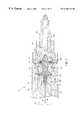
- FIG. 1is a side sectional view of the distal end of an injection molding machine including the present polymer invention filtration apparatus.
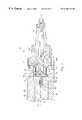
- FIG. 2is a side sectional view of the injection molding machine and filtration apparatus of FIG. 1 in which the screw is translated backward to accumulate molten polymer in front of the screw.
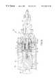
- FIG. 3is a side sectional view of the injection molding machine and the filtration apparatus of FIG. 1 in which the screw is translated forward in a polymer injection stroke.
- FIG. 4is a side sectional view of the injection molding machine and the filtration apparatus of FIG. 1 in which the screw is positioned forward for purging contaminants from the filter.
- FIG. 5is a side sectional view of the distal end of an injection molding machine including another preferred polymer filtration apparatus.
- FIG. 6is a front view of the ring member of FIG. 5 .
- FIG. 7is a side sectional view of the injection molding machine and filtration apparatus of FIG. 5 with the screw translated forward in a polymer injection stroke.
- FIG. 8is a side sectional view of the injection molding machine and filtration apparatus of FIG. 5 in which the screw is positioned forward for purging contaminants from the filter.
- FIG. 9is a side sectional view of the distal end of an injection molding machine including yet another preferred polymer filtration apparatus.
- FIG. 10is a side sectional view of the injection molding machine and filtration apparatus of FIG. 9 with the screw translated forward in a polymer injection stroke.
- FIG. 11is a side sectional view of the injection molding machine and filtration apparatus of FIG. 9 with the screw positioned forward for purging contaminants from the filter.
- FIG. 12is a side sectional view of the distal end of an injection molding machine including still another preferred polymer filtration apparatus.
- FIG. 13is a front view of the ring member of FIG. 12 .
- FIG. 14is a side sectional view of the injection molding machine and filtration apparatus of FIG. 12 with the screw translated forward in a polymer injection stroke.
- FIG. 15is a side sectional view of the injection molding machine and filtration apparatus of FIG. 12 with the screw positioned forward for purging contaminants from the filter.
- polymer filtration apparatus 10is incorporated within the distal end of an injection molding machine 14 .
- Injection molding machine 14includes a powered elongate screw 16 housed within a constant diameter bore 38 extending through a barrel 14 a .
- Screw 16is rotatable in the direction of arrow 20 for plasticizing and melting polymer pellets fed into bore 38 .
- Screw 16is also translatable in the directions of arrows 18 and 46 (FIG. 3) for accumulating molten polymer within bore 38 and for forcing a single shot of molten polymer from bore 38 in an injection stroke into a mold (not shown).
- An end cap 30is mounted to the end of barrel 14 a with screws and has a narrowing bore 40 in communication with bore 38 .
- Bore 40has a constant diameter portion 40 a at the upstream end which extends into a tapering portion 40 b .
- the constant diameter portion 40 a at the upstream endhas a diameter that is slightly less than the diameter of bore 38 , thereby forming an annular shoulder 28 between bores 38 and 40 .
- a nozzle 32is secured to the downstream end of end cap 30 .
- Nozzle 32has a nozzle opening 42 in communication with bore 40 .
- Nozzle 32engages with the mold for directing polymer into the mold.
- a tip member 22is secured to the distal end of screw 16 .
- Tip member 22has a mounting shaft 44 which engages a hole 41 at the distal end of screw 16 for securing tip member 22 to the distal end of screw 16 .
- Mounting shaft 44has a proximal smooth diameter portion 44 b and a distal threaded portion 44 a .
- the smooth diameter portion 44 b of shaft 44mates with a smooth bore portion 41 a of hole 41 for locating tip member 22 concentrically relative to axis X of screw 16 while the threaded portion 44 a of shaft 44 engages threaded hole portion 41 b of hole 41 for securing tip member 22 thereon.
- a circular upstream flange 24extends from mounting shaft 44 and abuts the distal end of screw 16 when tip member 22 is secured thereon.
- a circular downstream flange 26is axially spaced apart from upstream flange 24 by an intermediate shaft portion 22 a extending therebetween. The opposing faces of flanges 24 and 26 are separated by a distance L 1 .
- the diameters of flanges 24 and 26are smaller than bore 38 to form respective annular gaps or passages 11 and 13 therebetween.
- the diameter of downstream flange 26is less than the diameter of constant diameter portion 40 a of bore 40 for allowing flange 26 to extend therein, as discussed later.
- flanges 24 and 26are greater than the diameter of intermediate shaft portion 22 a so that the flanges 24 / 26 , intermediate shaft portion 22 a and ring member 34 (discussed below), define an annular region 36 therebetween.
- Downstream flange 26has a series of filter holes 26 a extending axially therethrough parallel to the axis X of screw 16 .
- the series of filter holes 26 aforms a filter for filtering contaminants 19 from molten polymer forced downstream by the rotation of screw 16 .
- Tip 22 b of tip member 22extends from downstream flange 26 and tapers to a point to promote the smooth flow of polymer thereover.
- Tip member 22is preferably formed in two pieces with intermediate shaft portion 22 a being secured to upstream flange 24 by threaded portions, but alternatively, can be one piece.
- An annular ring member 34is slidably positioned within bore 38 and is positioned between the upstream 24 and downstream 26 flanges of tip member 22 .
- Ring member 34has a sliding fit with the inner surfaces of bore 38 and has an axial length L 2 that is slightly less than the axial distance L 1 between flanges 24 and 26 .
- the annular thickness t of ring member 34is greater that the annular width of annular gaps 11 / 13 between flanges 24 / 26 and bore 38 . This allows ring member 34 to act as a valve by sliding within bore 38 between flanges 24 and 26 to blocking either annular gap 11 or 13 .
- the upstream and downstream surfaces of ring member 34 , as well as the mating surfaces of flanges 24 / 26are shaped to form sealing surfaces therebetween when engaged.
- Tip member 22 and ring member 34are preferably made of tool steel but alternatively, can be made of other suitable hardened steels.
- the downstream surfaces of flange 24 and tip 22 bare preferably angled to promote the smooth flow of polymer thereover, alternatively, the downstream surfaces of flange 24 and tip 22 b can be perpendicular to axis X.
- filter holes 26 aare preferably about 500 microns in diameter but can vary between 200 microns and 5,000 microns depending upon the application at hand.
- Screw 16 of injection molding machine 14is rotated in the direction of arrow 20 to plasticize and melt polymer pellets fed into barrel 14 a .
- screw 16is translated backwardly in the direction of arrow 18 from the position of FIG. 1 to that of FIG. 2 to allow molten polymer to accumulate downstream from screw 16 .
- the molten polymerflows axially towards and through the filter holes 26 a of downstream flange 26 , and then over tip 22 b .
- the filtered molten polymeraccumulates downstream from screw 16 and tip member 22 within bore 38 , passage 40 and nozzle opening 42 .
- FIG. 3depicts screw 16 in the forward position at the end of the injection stroke.
- downstream flange 26is positioned past shoulder 28 a distance that is about (L 1 ⁇ L 2 )/2, where L 1 is the distance between flanges 24 / 26 and L 2 is the axial length of ring member 34 .
- there is a gap or passage 15 between the upstream flange 24 and ring member 34and a gap or passage 17 between the downstream flange 26 and ring member 34 . Consequently, molten polymer can flow around tip member 22 to flush out or purge contaminants 19 captured within annular region 36 behind downstream flange 26 for discharge through nozzle 32 .
- the operation of filtration apparatus 10does not require any handling or changing of filter elements by the operator and the injection molding machine 14 can be programmed to automatically purge the contaminants 19 on a timed basis or when the pressure within barrel 14 a exceeds a predetermined level.
- the screw 16encounters less resistance during the injection stroke and is able to move forwardly more quickly. This allows quicker injection of the molten polymer into the mold which increases the speed and capacity of the injection molding machine 14 .
- the present invention polymer filtration apparatus 10does not require any special passages, recesses or channels formed in the barrel 14 a or the bore 38 . As a result, polymer filtration apparatus 10 can be incorporated into most existing injection molding machines by the installation of a tip member 22 , ring member 34 , end cap 30 and nozzle 32 .
- filtration apparatus 50differs from filtration apparatus 10 in that tip member 60 has a solid downstream flange 66 .
- ring member 48has a radial wall 54 with opposing upstream 58 and downstream 56 walls connected to opposite ends thereof.
- Radial wall 54extends concentrically around axis X while the upstream 58 and downstream 56 walls extend radially outwardly from radial wall 54 .
- Radial wall 54has a series of filter holes 54 a extending radially therethrough.
- Downstream wall 56includes a series of arched passages 52 extending axially therethrough (FIG. 6) along the outer radial edge of downstream wall 56 .
- Walls 58 , 56 and 54define the ends and inner perimeter of an annular region 62 .
- the outer perimeter of annular region 62is defined by bore 38 .
- the flow path of the molten polymer as indicated by arrows Faxially passes upstream flange 24 through annular gap 11 and flows radially inwardly into annular region 36 .
- the molten polymerflows radially outwardly into the annular region of ring member 48 through the filter holes 54 a in radial wall 54 .
- the polymerthen flows axially towards and through the openings 52 in downstream wall 56 , past downstream flange 66 through annular gap 13 , and over tip 22 b.
- the molten polymerflows axially through annular region 36 and then radially outwardly through gap 17 .
- the polymerthen flows axially past downstream flange 66 through gap 13 , over tip 22 b , through bore 40 , and out through nozzle opening 42 of nozzle 32 .
- filtration apparatus 70differs from filtration apparatus 10 in that tip member 68 has a solid downstream flange 66 and a central bore 76 extending outwardly through tip 22 b .
- a series of filter holes 78extend radially inwardly into intermediate shaft portion 22 a to central bore 76 .
- the molten polymerflows axially through annular region 36 and then radially outwardly through gap 17 to flow axially past downstream flange 66 through gap 13 .
- the polymerthen flows over tip 22 b , through bore 40 , and out through nozzle opening 42 of nozzle 32 .
- a tubular filter screen 79can be optionally included for removing contaminants 19 .
- Filter screen 79is installed by separating intermediate shaft portion 22 a from upstream flange 24 and slipping filter screen 79 over intermediate shaft portion 22 a . Intermediate shaft portion 22 a is then resecured to upstream flange 24 .
- Filter screen 79preferably has a pore size of 10 microns to 1000 microns with 100 microns being the most preferred. If a filter screen 79 is employed, filter holes 78 within intermediate shaft portion 22 a can be enlarged to preferably about 5,000 microns. Alternatively, depending upon the application at hand, filter holes 78 can range between 2,000 microns and 10,000 microns when a filter screen 79 is used.
- filtration apparatus 90differs from filtration apparatus 50 in that tip member 82 includes an upstream flange 84 having a shoulder 98 and a downstream flange 86 with a series of large axial openings 86 a therethrough.
- ring member 88has an upstream wall 92 and a downstream wall 94 with a series of respective axial openings 92 a and 94 a therethrough.
- the polymerthen flows radially inwardly through the filter holes 54 a of radial wall 54 into annular region 36 , axially through the openings 86 a in downstream flange 86 and over tip 22 b .
- Contaminants 19are trapped behind filter holes 54 a within annular region 62 .
- the flow path of the molten polymerflows axially past upstream flange 84 through gap 11 , radially inwardly through gap 15 , axially through openings 92 a in upstream wall 92 of ring member 88 , axially through annular region 62 , axially through openings 94 a in downstream wall 94 of ring member 88 , radially outwardly through gap 17 , axially past downstream flange 86 through gap 13 , over tip 22 b , through bore 40 , and out through the nozzle opening 42 of nozzle 32 .
- filtration apparatuses 10 , 50 , 70 and 90can be interchanged.
- filtration apparatuses 10 , 50 , 70 and 90can be installed within existing injection molding machines or included within new equipment.
- shoulder 28 of end cap 30has been shown and described as being employed as an end stop for preventing downstream travel of the ring members, alternatively, other suitable methods of providing an end stop can be employed.
- a shouldercan be machined within bore 38
- a sleevecan be fitted within bore 38
- small protrusionscan be formed or installed within bore 38 .
- the ring membersare preferably positioned midway between the flanges of the tip members during purging, during actual use, the ring members may sometimes be slightly closer to one of the flanges.
- a filter screencan be employed in filtration apparatuses 10 , 50 and 90 if desired.
Landscapes
- Chemical & Material Sciences (AREA)
- Chemical Kinetics & Catalysis (AREA)
- Engineering & Computer Science (AREA)
- Mechanical Engineering (AREA)
- Manufacturing & Machinery (AREA)
- Injection Moulding Of Plastics Or The Like (AREA)
Abstract
Description
Claims (33)
Priority Applications (4)
| Application Number | Priority Date | Filing Date | Title |
|---|---|---|---|
| US09/271,666US6168411B1 (en) | 1999-03-18 | 1999-03-18 | Polymer filtration method and apparatus |
| AU37607/00AAU3760700A (en) | 1999-03-18 | 2000-03-16 | Polymer filtration apparatus |
| PCT/US2000/007234WO2000054958A1 (en) | 1999-03-18 | 2000-03-16 | Polymer filtration apparatus |
| US09/528,391US6270703B1 (en) | 1999-03-18 | 2000-03-20 | Polymer filteration apparatus and method of use |
Applications Claiming Priority (1)
| Application Number | Priority Date | Filing Date | Title |
|---|---|---|---|
| US09/271,666US6168411B1 (en) | 1999-03-18 | 1999-03-18 | Polymer filtration method and apparatus |
Related Child Applications (1)
| Application Number | Title | Priority Date | Filing Date |
|---|---|---|---|
| US09/528,391Continuation-In-PartUS6270703B1 (en) | 1999-03-18 | 2000-03-20 | Polymer filteration apparatus and method of use |
Publications (1)
| Publication Number | Publication Date |
|---|---|
| US6168411B1true US6168411B1 (en) | 2001-01-02 |
Family
ID=23036549
Family Applications (2)
| Application Number | Title | Priority Date | Filing Date |
|---|---|---|---|
| US09/271,666Expired - LifetimeUS6168411B1 (en) | 1999-03-18 | 1999-03-18 | Polymer filtration method and apparatus |
| US09/528,391Expired - LifetimeUS6270703B1 (en) | 1999-03-18 | 2000-03-20 | Polymer filteration apparatus and method of use |
Family Applications After (1)
| Application Number | Title | Priority Date | Filing Date |
|---|---|---|---|
| US09/528,391Expired - LifetimeUS6270703B1 (en) | 1999-03-18 | 2000-03-20 | Polymer filteration apparatus and method of use |
Country Status (3)
| Country | Link |
|---|---|
| US (2) | US6168411B1 (en) |
| AU (1) | AU3760700A (en) |
| WO (1) | WO2000054958A1 (en) |
Cited By (9)
| Publication number | Priority date | Publication date | Assignee | Title |
|---|---|---|---|---|
| US20040166191A1 (en)* | 2003-02-20 | 2004-08-26 | Graham Packaging Company, L.P. | Reservoir reducing screw tip |
| US20040200784A1 (en)* | 2003-04-10 | 2004-10-14 | Psi-Polymer Systems Inc. | Filtration apparatus for polymer processing and method |
| JP2014527471A (en)* | 2011-03-12 | 2014-10-16 | ハスキー インジェクション モールディング システムズ リミテッドHusky Injection Molding Systems Limited | Plasticizing and injection equipment |
| US9090002B2 (en) | 2011-10-06 | 2015-07-28 | Kolcor Technologies LLC | Sealing device in a polymer filtration device |
| WO2016095022A1 (en) | 2014-12-15 | 2016-06-23 | Husky Injection Molding Systems Ltd. | Injection molding machine |
| US10933357B2 (en)* | 2016-10-17 | 2021-03-02 | Next Generation Analytics Gmbh | Filter system for viscous or highly viscous liquids, in particular plastic melts and method for filtering viscous or highly viscous liquids |
| US20220355531A1 (en)* | 2018-05-07 | 2022-11-10 | PSI-Polymer Systems, Inc. | Filtration apparatuses and screen changer devices for polymer processing and related methods |
| AT526285A1 (en)* | 2022-07-11 | 2024-01-15 | Engel Austria Gmbh | Plasticizing unit for a molding machine |
| US20240278500A1 (en)* | 2021-06-07 | 2024-08-22 | Innotech Europe B.V. | Extruder system and additive manufacturing printer, comprising such an extruder |
Families Citing this family (27)
| Publication number | Priority date | Publication date | Assignee | Title |
|---|---|---|---|---|
| JP3549101B2 (en)* | 2000-06-16 | 2004-08-04 | 日精樹脂工業株式会社 | Injection device with check valve |
| EP1512515A1 (en)* | 2000-09-19 | 2005-03-09 | Fuji Photo Film Co., Ltd. | Method for recycling plastic products |
| JP3689348B2 (en)* | 2001-05-02 | 2005-08-31 | 株式会社日本製鋼所 | Wood flour compound pellet granulation method and apparatus |
| DE10210464B4 (en)* | 2002-03-09 | 2007-07-26 | Demag Ergotech Gmbh | backflow |
| DE10326487A1 (en)* | 2003-06-10 | 2005-01-05 | Gneuß Kunststofftechnik GmbH | Device for providing a melt |
| US20050062198A1 (en)* | 2003-09-19 | 2005-03-24 | Phong Pham | Automated method of injecting polymer to form a graphical design onto substrate |
| US20050136146A1 (en)* | 2003-12-18 | 2005-06-23 | Phong Pham | Apparatus for automated method of injecting polymer to form a graphical design onto substrates |
| US7284978B2 (en)* | 2005-06-30 | 2007-10-23 | Husky Injection Molding Systems Ltd. | Brake for molding machine valve |
| EP1872839A1 (en)* | 2006-06-30 | 2008-01-02 | NV Bekaert SA | A filter candle comprising an elongated mesh pack |
| US8088119B2 (en)* | 2007-02-01 | 2012-01-03 | Laurimed, Llc | Methods and devices for treating tissue |
| US7527493B1 (en)* | 2007-11-01 | 2009-05-05 | Md Plastics Incorporated | Precise control non-return valve |
| US20110247940A1 (en)* | 2010-04-13 | 2011-10-13 | Chien-Ming Huang | Method for Forming Multiple Colors on an Aluminum Alloy Structure |
| US8685052B2 (en) | 2010-06-30 | 2014-04-01 | Laurimed, Llc | Devices and methods for cutting tissue |
| CN103068327B (en) | 2010-06-30 | 2015-08-05 | 劳瑞弥徳有限责任公司 | For excising and withdraw from the apparatus and method of tissue |
| US20120111426A1 (en)* | 2010-11-10 | 2012-05-10 | Panos Trakas | Dual stage screen pack with decompression feature |
| WO2013119336A1 (en) | 2012-02-10 | 2013-08-15 | Laurimed, Llc | Vacuum powered rotary devices and methods |
| US8815099B1 (en)* | 2014-01-21 | 2014-08-26 | Laurimed, Llc | Devices and methods for filtering and/or collecting tissue |
| DE102014101776A1 (en)* | 2014-02-12 | 2015-08-13 | Nordson Pps Gmbh | Grobpartikelabscheidevorrichtung |
| CH710340A1 (en) | 2014-11-06 | 2016-05-13 | Fostag Formenbau Ag | Co-injection nozzle for an injection molding apparatus for manufacturing multi-layer injection molding products. |
| CH710339A1 (en)* | 2014-11-06 | 2016-05-13 | Fostag Formenbau Ag | Co-injection nozzle with integrated check valve for an injection molding apparatus for manufacturing multi-layer injection molding products. |
| WO2016081077A1 (en)* | 2014-11-19 | 2016-05-26 | Exxonmobil Chemical Patents Inc. | Structural element for gel reducing, as well as gel reducing apparatus and method |
| EP3088157B1 (en)* | 2015-04-30 | 2021-05-12 | Fimic S.r.l. | Filter for plastic material |
| EP3806756B1 (en) | 2018-06-13 | 2024-01-03 | Stryker European Operations Limited | Bone fragment collector and processor |
| CN110509518B (en)* | 2019-08-28 | 2021-07-30 | 安徽金诚汽车装饰设计开发有限公司 | Extrusion molding mechanism for automobile decorative plate |
| EP4076290B1 (en) | 2019-12-18 | 2024-07-31 | Stryker European Operations Limited | Bone fragment collector and processor |
| CN111497174B (en)* | 2020-04-19 | 2022-01-11 | 广西膜宝包科技发展有限公司 | Working method of plastic blow molding automatic net changing structure and butt joint device thereof |
| DE102021105197A1 (en) | 2021-03-04 | 2022-09-08 | Erwin Quarder Systemtechnik Gmbh | non-return valve |
Citations (49)
| Publication number | Priority date | Publication date | Assignee | Title |
|---|---|---|---|---|
| US1163740A (en) | 1913-08-12 | 1915-12-14 | William Davies Company Ltd | Apparatus and process for making tubes. |
| US1595470A (en) | 1924-05-12 | 1926-08-10 | Edgar H Johnson | Extruding machine |
| US2257067A (en) | 1937-12-07 | 1941-09-23 | American Plastics Corp | Method and apparatus for making casein plastics |
| US2374468A (en) | 1940-12-21 | 1945-04-24 | Opel Fritz Von | Injection molding apparatus |
| US2636218A (en) | 1951-01-27 | 1953-04-28 | Nixon Nitration Works | Extrusion die unit for molding plastic materials |
| US2653351A (en) | 1951-12-12 | 1953-09-29 | Western Electric Co | Apparatus for advancing and working elastomer compounds |
| US2770836A (en) | 1953-06-10 | 1956-11-20 | Monsanto Chemicals | Pressure head for extruders |
| US2864126A (en) | 1954-11-08 | 1958-12-16 | Western Electric Co | Plastics extrusion apparatus |
| US2895167A (en) | 1954-06-09 | 1959-07-21 | Mario Maccaferri | Filtering liner for barrels of extrusion machines |
| FR1272329A (en) | 1959-10-30 | 1961-09-22 | Du Pont | Apparatus for treating filament materials |
| US3335461A (en) | 1964-06-12 | 1967-08-15 | Lester Engineering Co | Reciprocating screw injection molding machine |
| FR1553319A (en) | 1968-01-29 | 1969-01-10 | ||
| US3495299A (en) | 1964-04-08 | 1970-02-17 | Rhone Poulenc Sa | Apparatus for the continuous filtration of molten plastics material |
| US3578741A (en) | 1968-05-31 | 1971-05-18 | Und Giesserel Netstal Ag Masch | Valve for a plastifying device |
| US3710988A (en) | 1970-09-21 | 1973-01-16 | E Moslo | Injection molding machine |
| DE2524746A1 (en) | 1975-06-04 | 1976-12-16 | Gerhard Prof Dr Ing Schenkel | Synthetic material injector with worm plasticiser - has filter flushed by force opened and closed back pressure valve |
| FR2324443A1 (en) | 1975-09-17 | 1977-04-15 | Netstal Ag Maschf Giesserei | PLASTICIZING DEVICE FOR PLASTIC INJECTION MOLDING MACHINES |
| US4077756A (en) | 1976-09-08 | 1978-03-07 | Peerless Machine & Tool Corporation | Injection molding extrusion mixer |
| US4174198A (en) | 1977-09-14 | 1979-11-13 | Nihon Repro Machine Kogyo Kabushiki Kaisha | Foreign material removing device in synthetic resin reclaiming machine |
| US4177234A (en) | 1977-10-05 | 1979-12-04 | Metals & Plastics, Inc. | Method and apparatus for cleaning thermoplastic materials |
| US4191648A (en) | 1978-02-06 | 1980-03-04 | Kaplan Stephen J | Filtration device for filtering temperature controlled fluids |
| US4257901A (en) | 1979-08-13 | 1981-03-24 | Western Electric Co., Inc. | Cleanable filter and method of cleaning same |
| US4332541A (en) | 1979-11-27 | 1982-06-01 | Hermann Berstorff Maschinenbau Gmbh | Filtering arrangement for thermoplastics materials |
| US4358262A (en) | 1980-11-15 | 1982-11-09 | Hermann Berstorff Maschinenbau Gmbh | Filter or tool-changing device for screw extruders |
| DE2541738C3 (en) | 1975-09-19 | 1983-12-01 | Battenfeld Maschinenfabriken Gmbh, 5882 Meinerzhagen | Injection device of an injection molding machine for processing plastic materials with a non-return valve |
| US4434053A (en) | 1982-07-06 | 1984-02-28 | Osuna Diaz J M | Two-stage filter for injection molding machine |
| US4477242A (en) | 1982-02-04 | 1984-10-16 | Krauss-Maffei Aktiengesellschaft | Backflow preventer for an injection molding machine |
| US4486304A (en) | 1982-06-17 | 1984-12-04 | Neuman Clayton L | Apparatus for continuously filtering plastic melt with noninterruptive purge |
| US4511472A (en) | 1983-03-30 | 1985-04-16 | Beringer Co., Inc. | Apparatus for continuous polymer filtration |
| US4512733A (en) | 1982-02-04 | 1985-04-23 | Krauss-Maffei Aktiengesellschaft | Adjustable injection molding backflow preventer |
| EP0172925A1 (en) | 1984-08-22 | 1986-03-05 | OKW ODENWALDER KUNSTSTOFFWERKE GmbH & Co | Impurities-removing filter for thermoplastic materials |
| US4627916A (en) | 1984-01-28 | 1986-12-09 | Odenwalder Kunststoffwerke Gmbh | Dirt filter for semifluid thermoplastic media |
| US4661249A (en) | 1985-01-28 | 1987-04-28 | Metallurgical Industries, Inc. | Prefilter device for polymeric material |
| US4714422A (en) | 1984-05-22 | 1987-12-22 | Farrel Corporation | Rotary plasticator screw injection machine |
| US4849113A (en) | 1988-05-23 | 1989-07-18 | Hills William H | Continuous polymer filter |
| WO1990003879A1 (en) | 1988-10-13 | 1990-04-19 | Seiki Corporation Co., Ltd. | Process and apparatus for injection molding |
| US4966539A (en) | 1988-05-12 | 1990-10-30 | Pena Juan R | Seal for piston screws in plastics injection and extrusion apparatus |
| US5122286A (en) | 1989-12-19 | 1992-06-16 | Kreyenborg Verwaltungen Und Beteiligungen Kg | Filter changing apparatus for flowable plastic material |
| US5141631A (en) | 1991-06-07 | 1992-08-25 | John Brown Inc. | Polymer filter with backflush pump |
| US5151025A (en) | 1989-10-26 | 1992-09-29 | Ewikon Entwicklung Und Konstruktion Gmbh & Co. Kg | Electrically heatable nozzle for an injection molding machine, a hot runner system or the like |
| US5246660A (en) | 1990-10-06 | 1993-09-21 | Seiki Corporation | Process and apparatus for injection molding with melt filtration and mixing |
| US5417866A (en) | 1993-07-02 | 1995-05-23 | Extek, Inc. | Continuous flow polymer filtration apparatus and process |
| US5456828A (en) | 1993-11-08 | 1995-10-10 | Zimmer Aktiengesellschaft | Polymer melt filtration apparatus |
| US5462653A (en) | 1994-02-15 | 1995-10-31 | Hills, Inc. | Apparatus for continuous polymer filtration |
| DE4426629A1 (en) | 1994-07-27 | 1996-02-01 | Gneuss Kunststofftechnik Gmbh | Filter for use between injection moulding cylinder and nozzle |
| US5507498A (en) | 1993-10-13 | 1996-04-16 | Synergy Extrusion Technologies, Inc. | Sealing device for polymer filtration apparatus |
| US5510030A (en) | 1992-02-14 | 1996-04-23 | Bacher; Helmut | Filter apparatus for flowable material |
| US5618423A (en) | 1996-07-23 | 1997-04-08 | Lin; Ping Ho | On-the-fly long-running rotary filtration screen device |
| US5783223A (en) | 1996-08-27 | 1998-07-21 | National Polymers Inc. | Plastic injection molding machine with continuous removal of particulate contaminants |
Family Cites Families (2)
| Publication number | Priority date | Publication date | Assignee | Title |
|---|---|---|---|---|
| DE19512826A1 (en)* | 1994-05-25 | 1995-11-30 | Herzog Ag | Injection moulding filter jet assembly |
| JPH11333893A (en)* | 1998-05-22 | 1999-12-07 | Sumitomo Heavy Ind Ltd | Backflow preventing device |
- 1999
- 1999-03-18USUS09/271,666patent/US6168411B1/ennot_activeExpired - Lifetime
- 2000
- 2000-03-16WOPCT/US2000/007234patent/WO2000054958A1/enactiveApplication Filing
- 2000-03-16AUAU37607/00Apatent/AU3760700A/ennot_activeAbandoned
- 2000-03-20USUS09/528,391patent/US6270703B1/ennot_activeExpired - Lifetime
Patent Citations (50)
| Publication number | Priority date | Publication date | Assignee | Title |
|---|---|---|---|---|
| US1163740A (en) | 1913-08-12 | 1915-12-14 | William Davies Company Ltd | Apparatus and process for making tubes. |
| US1595470A (en) | 1924-05-12 | 1926-08-10 | Edgar H Johnson | Extruding machine |
| US2257067A (en) | 1937-12-07 | 1941-09-23 | American Plastics Corp | Method and apparatus for making casein plastics |
| US2374468A (en) | 1940-12-21 | 1945-04-24 | Opel Fritz Von | Injection molding apparatus |
| US2636218A (en) | 1951-01-27 | 1953-04-28 | Nixon Nitration Works | Extrusion die unit for molding plastic materials |
| US2653351A (en) | 1951-12-12 | 1953-09-29 | Western Electric Co | Apparatus for advancing and working elastomer compounds |
| US2770836A (en) | 1953-06-10 | 1956-11-20 | Monsanto Chemicals | Pressure head for extruders |
| US2895167A (en) | 1954-06-09 | 1959-07-21 | Mario Maccaferri | Filtering liner for barrels of extrusion machines |
| US2864126A (en) | 1954-11-08 | 1958-12-16 | Western Electric Co | Plastics extrusion apparatus |
| FR1272329A (en) | 1959-10-30 | 1961-09-22 | Du Pont | Apparatus for treating filament materials |
| US3495299A (en) | 1964-04-08 | 1970-02-17 | Rhone Poulenc Sa | Apparatus for the continuous filtration of molten plastics material |
| US3335461A (en) | 1964-06-12 | 1967-08-15 | Lester Engineering Co | Reciprocating screw injection molding machine |
| FR1553319A (en) | 1968-01-29 | 1969-01-10 | ||
| US3578741A (en) | 1968-05-31 | 1971-05-18 | Und Giesserel Netstal Ag Masch | Valve for a plastifying device |
| US3710988A (en) | 1970-09-21 | 1973-01-16 | E Moslo | Injection molding machine |
| DE2524746A1 (en) | 1975-06-04 | 1976-12-16 | Gerhard Prof Dr Ing Schenkel | Synthetic material injector with worm plasticiser - has filter flushed by force opened and closed back pressure valve |
| FR2324443A1 (en) | 1975-09-17 | 1977-04-15 | Netstal Ag Maschf Giesserei | PLASTICIZING DEVICE FOR PLASTIC INJECTION MOLDING MACHINES |
| US4112516A (en) | 1975-09-17 | 1978-09-05 | Netstal-Maschinen Ag | Plasticizing device of an injection molding machine for plastics |
| DE2541738C3 (en) | 1975-09-19 | 1983-12-01 | Battenfeld Maschinenfabriken Gmbh, 5882 Meinerzhagen | Injection device of an injection molding machine for processing plastic materials with a non-return valve |
| US4077756A (en) | 1976-09-08 | 1978-03-07 | Peerless Machine & Tool Corporation | Injection molding extrusion mixer |
| US4174198A (en) | 1977-09-14 | 1979-11-13 | Nihon Repro Machine Kogyo Kabushiki Kaisha | Foreign material removing device in synthetic resin reclaiming machine |
| US4177234A (en) | 1977-10-05 | 1979-12-04 | Metals & Plastics, Inc. | Method and apparatus for cleaning thermoplastic materials |
| US4191648A (en) | 1978-02-06 | 1980-03-04 | Kaplan Stephen J | Filtration device for filtering temperature controlled fluids |
| US4257901A (en) | 1979-08-13 | 1981-03-24 | Western Electric Co., Inc. | Cleanable filter and method of cleaning same |
| US4332541A (en) | 1979-11-27 | 1982-06-01 | Hermann Berstorff Maschinenbau Gmbh | Filtering arrangement for thermoplastics materials |
| US4358262A (en) | 1980-11-15 | 1982-11-09 | Hermann Berstorff Maschinenbau Gmbh | Filter or tool-changing device for screw extruders |
| US4477242A (en) | 1982-02-04 | 1984-10-16 | Krauss-Maffei Aktiengesellschaft | Backflow preventer for an injection molding machine |
| US4512733A (en) | 1982-02-04 | 1985-04-23 | Krauss-Maffei Aktiengesellschaft | Adjustable injection molding backflow preventer |
| US4486304A (en) | 1982-06-17 | 1984-12-04 | Neuman Clayton L | Apparatus for continuously filtering plastic melt with noninterruptive purge |
| US4434053A (en) | 1982-07-06 | 1984-02-28 | Osuna Diaz J M | Two-stage filter for injection molding machine |
| US4511472A (en) | 1983-03-30 | 1985-04-16 | Beringer Co., Inc. | Apparatus for continuous polymer filtration |
| US4627916A (en) | 1984-01-28 | 1986-12-09 | Odenwalder Kunststoffwerke Gmbh | Dirt filter for semifluid thermoplastic media |
| US4714422A (en) | 1984-05-22 | 1987-12-22 | Farrel Corporation | Rotary plasticator screw injection machine |
| EP0172925A1 (en) | 1984-08-22 | 1986-03-05 | OKW ODENWALDER KUNSTSTOFFWERKE GmbH & Co | Impurities-removing filter for thermoplastic materials |
| US4661249A (en) | 1985-01-28 | 1987-04-28 | Metallurgical Industries, Inc. | Prefilter device for polymeric material |
| US4966539A (en) | 1988-05-12 | 1990-10-30 | Pena Juan R | Seal for piston screws in plastics injection and extrusion apparatus |
| US4849113A (en) | 1988-05-23 | 1989-07-18 | Hills William H | Continuous polymer filter |
| WO1990003879A1 (en) | 1988-10-13 | 1990-04-19 | Seiki Corporation Co., Ltd. | Process and apparatus for injection molding |
| US5151025A (en) | 1989-10-26 | 1992-09-29 | Ewikon Entwicklung Und Konstruktion Gmbh & Co. Kg | Electrically heatable nozzle for an injection molding machine, a hot runner system or the like |
| US5122286A (en) | 1989-12-19 | 1992-06-16 | Kreyenborg Verwaltungen Und Beteiligungen Kg | Filter changing apparatus for flowable plastic material |
| US5246660A (en) | 1990-10-06 | 1993-09-21 | Seiki Corporation | Process and apparatus for injection molding with melt filtration and mixing |
| US5141631A (en) | 1991-06-07 | 1992-08-25 | John Brown Inc. | Polymer filter with backflush pump |
| US5510030A (en) | 1992-02-14 | 1996-04-23 | Bacher; Helmut | Filter apparatus for flowable material |
| US5417866A (en) | 1993-07-02 | 1995-05-23 | Extek, Inc. | Continuous flow polymer filtration apparatus and process |
| US5507498A (en) | 1993-10-13 | 1996-04-16 | Synergy Extrusion Technologies, Inc. | Sealing device for polymer filtration apparatus |
| US5456828A (en) | 1993-11-08 | 1995-10-10 | Zimmer Aktiengesellschaft | Polymer melt filtration apparatus |
| US5462653A (en) | 1994-02-15 | 1995-10-31 | Hills, Inc. | Apparatus for continuous polymer filtration |
| DE4426629A1 (en) | 1994-07-27 | 1996-02-01 | Gneuss Kunststofftechnik Gmbh | Filter for use between injection moulding cylinder and nozzle |
| US5618423A (en) | 1996-07-23 | 1997-04-08 | Lin; Ping Ho | On-the-fly long-running rotary filtration screen device |
| US5783223A (en) | 1996-08-27 | 1998-07-21 | National Polymers Inc. | Plastic injection molding machine with continuous removal of particulate contaminants |
Cited By (16)
| Publication number | Priority date | Publication date | Assignee | Title |
|---|---|---|---|---|
| US20040166191A1 (en)* | 2003-02-20 | 2004-08-26 | Graham Packaging Company, L.P. | Reservoir reducing screw tip |
| WO2004074185A3 (en)* | 2003-02-20 | 2004-12-23 | Graham Packaging Co | Reservoir reducing screw tip |
| US6957953B2 (en)* | 2003-02-20 | 2005-10-25 | Graham Packaging Company, L.P. | Reservoir reducing screw tip |
| US20040200784A1 (en)* | 2003-04-10 | 2004-10-14 | Psi-Polymer Systems Inc. | Filtration apparatus for polymer processing and method |
| US7147774B2 (en) | 2003-04-10 | 2006-12-12 | Polymer Systems, Inc. | Sliding plate filter with segmented sealing ring |
| JP2014527471A (en)* | 2011-03-12 | 2014-10-16 | ハスキー インジェクション モールディング システムズ リミテッドHusky Injection Molding Systems Limited | Plasticizing and injection equipment |
| US9090002B2 (en) | 2011-10-06 | 2015-07-28 | Kolcor Technologies LLC | Sealing device in a polymer filtration device |
| WO2016095022A1 (en) | 2014-12-15 | 2016-06-23 | Husky Injection Molding Systems Ltd. | Injection molding machine |
| US10933357B2 (en)* | 2016-10-17 | 2021-03-02 | Next Generation Analytics Gmbh | Filter system for viscous or highly viscous liquids, in particular plastic melts and method for filtering viscous or highly viscous liquids |
| US20210162324A1 (en)* | 2016-10-17 | 2021-06-03 | Next Generation Analytics Gmbh | Filter system for viscous or highly viscous liquids, in particular plastic melts and method for filtering viscous or highly viscous liquids |
| US20220355531A1 (en)* | 2018-05-07 | 2022-11-10 | PSI-Polymer Systems, Inc. | Filtration apparatuses and screen changer devices for polymer processing and related methods |
| US12214536B2 (en)* | 2018-05-07 | 2025-02-04 | PSI-Polymer Systems, Inc. | Filtration apparatuses and screen changer devices for polymer processing and related methods |
| US20240278500A1 (en)* | 2021-06-07 | 2024-08-22 | Innotech Europe B.V. | Extruder system and additive manufacturing printer, comprising such an extruder |
| US12377608B2 (en)* | 2021-06-07 | 2025-08-05 | Albico Beheer B.V. | Extruder system and additive manufacturing printer, comprising such an extruder |
| AT526285A1 (en)* | 2022-07-11 | 2024-01-15 | Engel Austria Gmbh | Plasticizing unit for a molding machine |
| US12397490B2 (en) | 2022-07-11 | 2025-08-26 | Engel Austria Gmbh | Plasticizing unit for a molding machine |
Also Published As
| Publication number | Publication date |
|---|---|
| AU3760700A (en) | 2000-10-04 |
| WO2000054958A1 (en) | 2000-09-21 |
| US6270703B1 (en) | 2001-08-07 |
Similar Documents
| Publication | Publication Date | Title |
|---|---|---|
| US6168411B1 (en) | Polymer filtration method and apparatus | |
| EP1880085B1 (en) | Centrifugal oil mist separation device integrated in an axial hollow shaft of an internal combustion engine | |
| EP2651619B1 (en) | Apparatus for continuous filtering of mixed materials | |
| DE19983985B4 (en) | Automatic wire supply system of wire cut electrodischarge machine | |
| EP1084356B1 (en) | Sliding ring non-return valve | |
| US3767056A (en) | Injection molding filter | |
| EP3819073A1 (en) | Machine tool | |
| EP3689438B1 (en) | Cleaning device for bag filter | |
| DE102015110603B4 (en) | Machining machine and machining process | |
| AU652275B2 (en) | Positive-type non-return valve | |
| DE3319618A1 (en) | Coolant feed for cutting tools interchangeably accommodated in a work spindle | |
| WO2000016960A1 (en) | Device for producing plastic pipes | |
| JPH06206240A (en) | Filter nozzle device of injection molding machine | |
| EP3681690A1 (en) | Device and method for degassing and filtering polymer melts | |
| DE19742420A1 (en) | Rotor jet head for cleaning device | |
| DE102014009666A1 (en) | Melt filter arrangement with backwash screw conveyor | |
| EP3354440A1 (en) | Method for discharging polymer melt via a startup-valve, and startup-valve | |
| EP2069124A1 (en) | Decompression sprue bush and decompression machine nozzle | |
| DE102013012670B4 (en) | Oil centrifuge with centrifuge rotor | |
| DE8801793U1 (en) | Oscillating, turbine-driven liquid spray nozzle, especially for high-pressure cleaning equipment | |
| DE102016100225A1 (en) | Filter arrangement for a fluid | |
| DE4114019A1 (en) | A VALVE AND A SPELLING CHAMBER | |
| EP0456970A2 (en) | Apparatus for the continuous coating of cylindrical elements with elastic material | |
| DE9422037U1 (en) | Milling machine with quick tool change | |
| EP1932577B1 (en) | Cleaning device comprising a cleaning head and method for cleaning bag-type tube filters |
Legal Events
| Date | Code | Title | Description |
|---|---|---|---|
| AS | Assignment | Owner name:DYNISCO EXTRUSION, INC., NORTH CAROLINA Free format text:ASSIGNMENT OF ASSIGNORS INTEREST;ASSIGNOR:WILDMAN, PAUL D.;REEL/FRAME:010009/0996 Effective date:19990524 | |
| STCF | Information on status: patent grant | Free format text:PATENTED CASE | |
| FPAY | Fee payment | Year of fee payment:4 | |
| AS | Assignment | Owner name:ANTARES CAPITAL CORPORATION, AS AGENT, ILLINOIS Free format text:SECURITY AGREEMENT;ASSIGNORS:DYNISCO INSTRUMENTS LLC;DYNISCO EXTRUSION LLC;DYNISCO POLYMER TEST, INC.;AND OTHERS;REEL/FRAME:015562/0351 Effective date:20040712 | |
| AS | Assignment | Owner name:DYNISCO EXTRUSION, INC., MASSACHUSETTS Free format text:RELEASE OF ASSIGNMENT FOR SECURITY OF PATENTS;ASSIGNOR:COMERCIA BANK, AS AGENT;REEL/FRAME:015571/0253 Effective date:20040612 | |
| FEPP | Fee payment procedure | Free format text:PAYOR NUMBER ASSIGNED (ORIGINAL EVENT CODE: ASPN); ENTITY STATUS OF PATENT OWNER: LARGE ENTITY Free format text:PAYER NUMBER DE-ASSIGNED (ORIGINAL EVENT CODE: RMPN); ENTITY STATUS OF PATENT OWNER: LARGE ENTITY | |
| AS | Assignment | Owner name:DYNISCO EXTRUSION INC., MASSACHUSETTS Free format text:RELEASE BY SECURED PARTY;ASSIGNOR:ANTARES CAPITAL CORPORATION;REEL/FRAME:016937/0329 Effective date:20051018 Owner name:DYNISCO INSTRUMENTS LLC, MASSACHUSETTS Free format text:RELEASE BY SECURED PARTY;ASSIGNOR:ANTARES CAPITAL CORPORATION;REEL/FRAME:016937/0329 Effective date:20051018 Owner name:DYNISCO POLYMER TEST, INC., MASSACHUSETTS Free format text:RELEASE BY SECURED PARTY;ASSIGNOR:ANTARES CAPITAL CORPORATION;REEL/FRAME:016937/0329 Effective date:20051018 Owner name:DYNISCO BERINGER LLC, NORTH CAROLINA Free format text:RELEASE BY SECURED PARTY;ASSIGNOR:ANTARES CAPITAL CORPORATION;REEL/FRAME:016937/0329 Effective date:20051018 Owner name:DYNISCO LLC, MASSACHUSETTS Free format text:RELEASE BY SECURED PARTY;ASSIGNOR:ANTARES CAPITAL CORPORATION;REEL/FRAME:016937/0329 Effective date:20051018 Owner name:DYNISCO EXTRUSION LLC, MASSACHUSETTS Free format text:RELEASE BY SECURED PARTY;ASSIGNOR:ANTARES CAPITAL CORPORATION;REEL/FRAME:016937/0329 Effective date:20051018 | |
| AS | Assignment | Owner name:THE GOVENOR AND COMPANY OF THE BANK OF IRELAND, CO Free format text:FIRST LIEN SECURITY AGREEMENT;ASSIGNOR:DYNISCO EXTRUSION, INC.;REEL/FRAME:017025/0882 Effective date:20051018 Owner name:GSO CAPITAL PARTNERS, LP, NEW YORK Free format text:SECOND LIEN SECURITY AGREEMENT;ASSIGNOR:DYNISCO EXTRUSTION, INC.;REEL/FRAME:017025/0802 Effective date:20051018 | |
| AS | Assignment | Owner name:DYNISCO EXTRUSION, LLC, MASSACHUSETTS Free format text:RELEASE BY SECURED PARTY;ASSIGNOR:THE GOVERNOR AND COMPANY OF THE BANK OF IRELAND;REEL/FRAME:017336/0365 Effective date:20060320 Owner name:DYNISCO EXTRUSION LLC, MASSACHUSETTS Free format text:ASSIGNMENT OF ASSIGNORS INTEREST;ASSIGNOR:DYNISCO LLC, AS SUCCESSOR-IN-INTEREST TO DYNISCO EXTRUSION, INC.;REEL/FRAME:017336/0571 Effective date:20060320 Owner name:GENERAL ELECTRIC CAPITAL CORPORATION, ILLINOIS Free format text:SECURITY AGREEMENT;ASSIGNOR:XALOY EXTRUSION LLC (FORMERLY KNOWN AS DYNISCO EXTRUSION LLC);REEL/FRAME:017336/0756 Effective date:20060320 Owner name:DYNISCO EXTRUSION, LLC, MASSACHUSETTS Free format text:RELEASE BY SECURED PARTY;ASSIGNOR:GSO CAPITAL PARTNERS LP;REEL/FRAME:017336/0563 Effective date:20060320 | |
| FPAY | Fee payment | Year of fee payment:8 | |
| AS | Assignment | Owner name:XALOY EXTRUSION LLC, PENNSYLVANIA Free format text:CHANGE OF NAME;ASSIGNOR:DYNISCO EXTRUSION LLC;REEL/FRAME:021462/0930 Effective date:20060321 | |
| AS | Assignment | Owner name:XALOY EXTRUSION LLC, NORTH CAROLINA Free format text:RELEASE BY SECURED PARTY;ASSIGNOR:GENERAL ELECTRIC CAPITAL CORPORATION, AS AGENT;REEL/FRAME:021502/0409 Effective date:20080908 | |
| AS | Assignment | Owner name:GENERAL ELECTRIC CAPITAL CORPORATION, AS AGENT, IL Free format text:SECURITY AGREEMENT;ASSIGNOR:XALOY EXTRUSION LLC;REEL/FRAME:021511/0653 Effective date:20080908 | |
| AS | Assignment | Owner name:XALOY EXTRUSION, LLC, NORTH CAROLINA Free format text:RELEASE BY SECURED PARTY;ASSIGNOR:GENERAL ELECTRIC CAPITAL CORPORATION;REEL/FRAME:028474/0414 Effective date:20120621 Owner name:SPIREX CORPORATION, OHIO Free format text:RELEASE BY SECURED PARTY;ASSIGNOR:GENERAL ELECTRIC CAPITAL CORPORATION;REEL/FRAME:028474/0414 Effective date:20120621 Owner name:NEW CASTLE INDUSTRIES, INC., PENNSYLVANIA Free format text:RELEASE BY SECURED PARTY;ASSIGNOR:GENERAL ELECTRIC CAPITAL CORPORATION;REEL/FRAME:028474/0414 Effective date:20120621 Owner name:XALOY INCORPORATED, PENNSYLVANIA Free format text:RELEASE BY SECURED PARTY;ASSIGNOR:GENERAL ELECTRIC CAPITAL CORPORATION;REEL/FRAME:028474/0414 Effective date:20120621 | |
| REMI | Maintenance fee reminder mailed | ||
| FPAY | Fee payment | Year of fee payment:12 | |
| SULP | Surcharge for late payment | Year of fee payment:11 | |
| AS | Assignment | Owner name:NORDSON CORPORATION, OHIO Free format text:ASSIGNMENT OF ASSIGNORS INTEREST;ASSIGNOR:XALOY INCORPORATED;REEL/FRAME:029849/0843 Effective date:20130121 | |
| AS | Assignment | Owner name:XALOY HOLDINGS, INC., OHIO Free format text:ASSIGNMENT OF ASSIGNORS INTEREST;ASSIGNOR:NORDSON CORPORATION;REEL/FRAME:054945/0078 Effective date:20210118 |