US6168395B1 - Bistable microactuator with coupled membranes - Google Patents
Bistable microactuator with coupled membranesDownload PDFInfo
- Publication number
- US6168395B1 US6168395B1US09/117,919US11791998AUS6168395B1US 6168395 B1US6168395 B1US 6168395B1US 11791998 AUS11791998 AUS 11791998AUS 6168395 B1US6168395 B1US 6168395B1
- Authority
- US
- United States
- Prior art keywords
- membrane
- sections
- substrate
- electrostatic
- cavities
- Prior art date
- Legal status (The legal status is an assumption and is not a legal conclusion. Google has not performed a legal analysis and makes no representation as to the accuracy of the status listed.)
- Expired - Fee Related
Links
Images


Classifications
- F—MECHANICAL ENGINEERING; LIGHTING; HEATING; WEAPONS; BLASTING
- F16—ENGINEERING ELEMENTS AND UNITS; GENERAL MEASURES FOR PRODUCING AND MAINTAINING EFFECTIVE FUNCTIONING OF MACHINES OR INSTALLATIONS; THERMAL INSULATION IN GENERAL
- F16K—VALVES; TAPS; COCKS; ACTUATING-FLOATS; DEVICES FOR VENTING OR AERATING
- F16K99/00—Subject matter not provided for in other groups of this subclass
- F16K99/0001—Microvalves
- F—MECHANICAL ENGINEERING; LIGHTING; HEATING; WEAPONS; BLASTING
- F04—POSITIVE - DISPLACEMENT MACHINES FOR LIQUIDS; PUMPS FOR LIQUIDS OR ELASTIC FLUIDS
- F04B—POSITIVE-DISPLACEMENT MACHINES FOR LIQUIDS; PUMPS
- F04B43/00—Machines, pumps, or pumping installations having flexible working members
- F04B43/02—Machines, pumps, or pumping installations having flexible working members having plate-like flexible members, e.g. diaphragms
- F04B43/04—Pumps having electric drive
- F04B43/043—Micropumps
- F—MECHANICAL ENGINEERING; LIGHTING; HEATING; WEAPONS; BLASTING
- F15—FLUID-PRESSURE ACTUATORS; HYDRAULICS OR PNEUMATICS IN GENERAL
- F15C—FLUID-CIRCUIT ELEMENTS PREDOMINANTLY USED FOR COMPUTING OR CONTROL PURPOSES
- F15C5/00—Manufacture of fluid circuit elements; Manufacture of assemblages of such elements integrated circuits
- F—MECHANICAL ENGINEERING; LIGHTING; HEATING; WEAPONS; BLASTING
- F16—ENGINEERING ELEMENTS AND UNITS; GENERAL MEASURES FOR PRODUCING AND MAINTAINING EFFECTIVE FUNCTIONING OF MACHINES OR INSTALLATIONS; THERMAL INSULATION IN GENERAL
- F16K—VALVES; TAPS; COCKS; ACTUATING-FLOATS; DEVICES FOR VENTING OR AERATING
- F16K99/00—Subject matter not provided for in other groups of this subclass
- F16K99/0001—Microvalves
- F16K99/0003—Constructional types of microvalves; Details of the cutting-off member
- F16K99/0015—Diaphragm or membrane valves
- F—MECHANICAL ENGINEERING; LIGHTING; HEATING; WEAPONS; BLASTING
- F16—ENGINEERING ELEMENTS AND UNITS; GENERAL MEASURES FOR PRODUCING AND MAINTAINING EFFECTIVE FUNCTIONING OF MACHINES OR INSTALLATIONS; THERMAL INSULATION IN GENERAL
- F16K—VALVES; TAPS; COCKS; ACTUATING-FLOATS; DEVICES FOR VENTING OR AERATING
- F16K99/00—Subject matter not provided for in other groups of this subclass
- F16K99/0001—Microvalves
- F16K99/0034—Operating means specially adapted for microvalves
- F16K99/0042—Electric operating means therefor
- F16K99/0051—Electric operating means therefor using electrostatic means
- H—ELECTRICITY
- H01—ELECTRIC ELEMENTS
- H01H—ELECTRIC SWITCHES; RELAYS; SELECTORS; EMERGENCY PROTECTIVE DEVICES
- H01H59/00—Electrostatic relays; Electro-adhesion relays
- H01H59/0009—Electrostatic relays; Electro-adhesion relays making use of micromechanics
- H—ELECTRICITY
- H02—GENERATION; CONVERSION OR DISTRIBUTION OF ELECTRIC POWER
- H02N—ELECTRIC MACHINES NOT OTHERWISE PROVIDED FOR
- H02N1/00—Electrostatic generators or motors using a solid moving electrostatic charge carrier
- H02N1/002—Electrostatic motors
- H02N1/006—Electrostatic motors of the gap-closing type
- F—MECHANICAL ENGINEERING; LIGHTING; HEATING; WEAPONS; BLASTING
- F16—ENGINEERING ELEMENTS AND UNITS; GENERAL MEASURES FOR PRODUCING AND MAINTAINING EFFECTIVE FUNCTIONING OF MACHINES OR INSTALLATIONS; THERMAL INSULATION IN GENERAL
- F16K—VALVES; TAPS; COCKS; ACTUATING-FLOATS; DEVICES FOR VENTING OR AERATING
- F16K99/00—Subject matter not provided for in other groups of this subclass
- F16K99/0001—Microvalves
- F16K2099/0069—Bistable microvalves
- F—MECHANICAL ENGINEERING; LIGHTING; HEATING; WEAPONS; BLASTING
- F16—ENGINEERING ELEMENTS AND UNITS; GENERAL MEASURES FOR PRODUCING AND MAINTAINING EFFECTIVE FUNCTIONING OF MACHINES OR INSTALLATIONS; THERMAL INSULATION IN GENERAL
- F16K—VALVES; TAPS; COCKS; ACTUATING-FLOATS; DEVICES FOR VENTING OR AERATING
- F16K99/00—Subject matter not provided for in other groups of this subclass
- F16K2099/0073—Fabrication methods specifically adapted for microvalves
- F16K2099/0074—Fabrication methods specifically adapted for microvalves using photolithography, e.g. etching
- F—MECHANICAL ENGINEERING; LIGHTING; HEATING; WEAPONS; BLASTING
- F16—ENGINEERING ELEMENTS AND UNITS; GENERAL MEASURES FOR PRODUCING AND MAINTAINING EFFECTIVE FUNCTIONING OF MACHINES OR INSTALLATIONS; THERMAL INSULATION IN GENERAL
- F16K—VALVES; TAPS; COCKS; ACTUATING-FLOATS; DEVICES FOR VENTING OR AERATING
- F16K99/00—Subject matter not provided for in other groups of this subclass
- F16K2099/0073—Fabrication methods specifically adapted for microvalves
- F16K2099/008—Multi-layer fabrications
- G—PHYSICS
- G11—INFORMATION STORAGE
- G11C—STATIC STORES
- G11C23/00—Digital stores characterised by movement of mechanical parts to effect storage, e.g. using balls; Storage elements therefor
- H—ELECTRICITY
- H01—ELECTRIC ELEMENTS
- H01H—ELECTRIC SWITCHES; RELAYS; SELECTORS; EMERGENCY PROTECTIVE DEVICES
- H01H1/00—Contacts
- H01H1/0036—Switches making use of microelectromechanical systems [MEMS]
- H01H2001/0042—Bistable switches, i.e. having two stable positions requiring only actuating energy for switching between them, e.g. with snap membrane or by permanent magnet
Definitions
- the inventionconcerns a bistable electrostatic actuator with pneumatic or liquid coupling.
- bistable acuatorsare of considerable importance.
- electrostatic drivesare often preferred to electromagnetic and thermomechanic actuators.
- a drawback of electrostaticsis its low range. High voltages are needed to achieve large deflections.
- Different conceptshave been reported to produce non-planar driving electrodes 4,5,6,7 . These technologies are however rather specific and not for general-purpose use. Further prior art is sensitive, since electrodes are free to the environment, e.g. particles. This can be improved, when enclosed electrodes, separated from the gaseous or liquid medium are formed 4 .
- One of the underlying problems addressed by the inventionis the reduction of deflection voltage to make the actuator suitable for a general purpose use.
- two buckled membranesspan over connected cavities with enclosed driving electrodes.
- the membranesoperate in counteraction, if one membrane section is pulled down electrostatically, the other membrane section is pushed up and vice versa.
- the couplingmay be air (pneumatic) or liquid,
- the actuator moduleis designed to achieve a deflection of ⁇ 10 ⁇ m and can be integrated in a microvalve for controlling the flow of fluids.
- the electrostatic driving principleis used in examples for a valve application, e.g. an on/off valve or a multi-way-valve, a switch application, e.g. an on/off-switch or a changeover switch, a micropump application.
- Grey-tone lithographymay be applied to fabricate the curved driving electrodes on the curved cavity bottom Compared to flat electrodes the driving voltage can thus be reduced up to a factor of five.
- the curved cavity bottom (“dimple”)also improves the pneumatic or liquid coupling since the enclosed air or liquid volume is minimized.
- the design and technology of the bistable electrostatic actuator with enclosed electrodes for a microvalve applicationuses curved shape of the electrodes by employing grey-tone lithography, a method to produce arbitrary relief-type surfaces.
- a pneumatic coupling of two cavitiesis incorporated slightly related to the suggestion 8 of MEMS 92, Travem ⁇ umlaut over (u) ⁇ nde.
- the two buckling sections of the membraneare oppositely stable (claim 15 ) and close to each other in the same wafer.
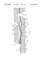
- FIG. 1is a schematic cross-section of the a bistable microvalve with two buckling membrane sections 20 a, 20 b of a membrane 20 .
- FIG. 1 ais a total view of the membrane 20 with the buckling sections 20 a, 20 b in a top view and considerably enlarged.
- FIG. 1 bis a side view in section of only one smoothly curved flat dimple with an overlying buckling membrane, representing both membrane sections 20 a, 20 b and both dimples 11 , 12 of FIG. 1 .
- FIG. 1 cshows a comparative example having a flat shaped electrode 21 f below the membrane section 20 a.
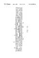
- FIG. 2shows an exploded view of the bistable microvalve of FIG. 1 . Visible is a coupling channel 30 between the cavities 11 , 12 . The outlet 8 is just behind the channel 30 .
- FIG. 2 ais the side view of the anodic bonded three part embodiment as seen in FIG. 2, having an actuator chip 100 with bonded membrane 20 and on top the valve seat chip 200 .
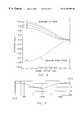
- FIG. 3is a finite-element calculation of the buckling of circular membranes, 2 mm (A-points) and 3 mm ( ⁇ umlaut over (O) ⁇ -points) in diameter.
- the membraneshave a silicon thickness of 7 ⁇ m and are covered single sided with silicon oxide.
- FIG. 4is an iterative electrostatic finite-element calculation of the snapping process of bistable membrane sections 20 a, 20 b in the membrane 20 .
- the stepsare marked ( 1 ) . . . ( 5 ).
- FIG. 5is a profile plot of a grey-tone lithograhic structured hollow (dimple) in silicon. This substantially cosinus-square contour is the optimum shape for the dimple bottom with associated driving electrodes.
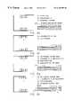
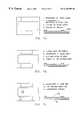
- FIG. 6 hare steps ( 1 ) to ( 22 ) in an exemplary manufacturing process to provide the actuator chip 100 with bonded membrane 20 .
- Each step of manufacturingis represented in the figures; each FIG. 6 a to 6 h simultaniously shows a section in side view (righthand) and top view (lefthand).
- FIG. 7 care an exemplary process with manufacturing steps ( 1 ) to ( 11 ) for providing the valve seat 200 , to be anodic bonded to the actuator chip turned upside down and shown in FIG. 2 a as side sectional view.
- the buckling of the membrane 20is for clarity reasons not shown in FIGS. 6, 7 and 2 a, but in the schematic views of FIG. 1 and 1 b, 1 c.
- FIG. 8is a three/two way valve with two outlets 8 a and 8 b and on inlet 7 .
- FIG. 9is an electronic switch providing a contact above membrane section 20 a.
- the contactis shown in closed condition wherein the metallic valve seat 9 a cooperates with a metallic contact section 28 a, applied to the top of the membrane section 20 a.
- a second cooperating contact pair 9 b, 28 bis provided associated to membrane section 20 b.
- two contacts A, Bare provided, which can be operated as changeover switch, depending on the metallic structures connecting the contact sections 28 a, 28 b.
- FIG. 11are micropump applications.
- An electrostatic attraction force at membrane 20 ais transferred via the channel 30 in a repulsing force for membrane section 20 b.
- a “repulsing electrostatic force”is generated, although physically only attracting electrostatic forces can be generated.
- the space below the membrane section 20 a, 20 bis a closed cavity 11 , 12 , 30 , not changing its volume and providing steady stationary and dynamic coupling.
- FIG. 1shows a schematic cross-section of a first example of a valve with buckling membranes.
- FIG. 2shows an exploded view of the bistable microvalve.
- FIG. 2 ais its side view. The manufacturing of FIGS. 6 and 7 leads to the FIG. 2 a embodiment.
- the lower active chip 100 of the valvecontains two silicon membranes 20 b, 20 b, which are buckling due to intrinsic compressive stress.
- the cavities 11 , 12 below the closely spaced membranes 20 a , 20 bare air-filled and connected by a channel 30 .
- the membranesare pneumatically coupled in order to operate in counteraction.
- Each membrane section 20 a , 20 bcan be switched down by electrostatic forces using an underlying driving electrode 21 and 22 as can also be seen from FIG. 8, which displays the same principle of membrane buckling in a multi-way application (3/2 way valve).
- By switching one membrane downthe air is pressed through the channel 30 and pushes the second membrane up.
- the use of two coupled membraneshas the advantage that the valve can be operated electrostatically in both directions without applying a voltage across the fluid.
- the actuatoris separated from the medium.
- Another advantage of the coupled membranesis its insensitivity against external pressure changes.
- the electrodes 21 , 22are curved to decrease the gap towards the outside clamping areas 20 c , 20 d. Thus the electrostatic forces are increased and/or the switching voltage can be reduced.
- the electrodes 21 , 22are implanted in the dimples to allow a Si—Si bonding process for the membrane formation without metallic feedthroughs.
- the pneumatic couplingis improved by the curved cavity bottom 11 , 12 .
- the enclosed air volumeis as small as possible.
- valve seat 9 amay be metallic, to provide switch applications according to FIG. 9 .
- the buckled membranes 20 a, 20 bare provided with metallic layers, cooperating with the electrodes 21 , 22 on the bottom of the cavities 11 , 12 .
- the electrodes 21 , 22 and the metallic layerscan be supplied via contact paths.
- Contact pad 2 aconnects via contact path 2 b to electrode 21 as shown and contact pad 2 a is applied near or in further distance of the valve, shown in FIG. 8 or 1 .
- the substrate 10is identified as actuator chip 100 in FIG. 2 a and manufactured according to FIGS. 6 a to 6 h.
- the valve seat chip 9is identified as upper chip 200 in FIG. 2 a and manufactured according to FIG. 7 a to 7 c.
- An inlet 7 and outlet 8is provided close to one of the membranes 20 a each passage 7 , 8 is provided in one of the valve seat chip 9 (corresponding to the upper chip 200 ) and the substrate 10 (corresponding to the actuator chip 100 ).
- the flow direction of inlet and outletmay be reversed.
- a valve seat 9 ais provided opposite the buckling area 20 a above cavity 12 , in which the electrode 22 is provided.
- the membrane section 20 adirectly cooperates with the valve seat, although according to FIG. 9 a contact pad may be provided between them, however for a different use.
- the center deflection d 0grows proportional to sqrt ( ⁇ / ⁇ cr ⁇ 1).
- the target specification of the valve of FIG. 1is to have a center membrane deflection of ⁇ 10 ⁇ m.
- the mechanical force to switch the buckled membraneshould be about 1 mN. This leads to a design with a silicon membrane thickness of 7 ⁇ m.
- Membranes with diameters of 2 mm and 3 mmwere investigated. The membranes are fabricated as a double layer of stress-free single-crystal silicon covered with thin silicon oxide on one side. For thermally grown SiO 2 an intrinsic compressive stress of about 3.10 8 N/m2 has been measured.
- the manufacturing of such membrane 20is step by step shown in FIGS. 6 d, 6 e steps ( 10 ) to ( 13 ).
- the electromechanical behaviour of the bistable membrane 20has been calculated with finite-element-analysis (FEA) using ANSYS software.
- FEAfinite-element-analysis
- FIG. 34 the FEA result of 7 ⁇ m thick silicon membranes is given.
- Above thresholdthe deflection increases with the square-root of the SiO 2 thickness (single sided with silicon oxide).
- the 2 mm membraneuses 585 nm silicon oxide, the 3 mm membrane 240 nm silicon oxide to buckle 10 ⁇ m.
- the thickness of the SiO 2 layerwas fixed in order to achieve a deflection of 10 ⁇ m.
- Table 1The major results of the calculation are given in Table 1 below.
- Table 1shows the results of the FEA for 7 ⁇ m thick silicon membranes covered on one side with silicon oxide.
- the SiO 2 thicknessis determined in order to obtain buckling with a 10 ⁇ m center deflection.
- the mechanical forces to snap the membranesare 1.35 mN and 0.60 mN, respectively.
- the electrostatic switching voltagesstrongly depend on the distance and shape of the lower driving electrodes. Two examples are shown in FIG. 1 b and 1 c. In FIG. 1 c a flat electrode 21 f on the bottom of a 10 ⁇ m deep cavity is assumed. In FIG. 1 b curved electrodes 21 , 22 with the cos 2 -shape, substantially corresponding to each down-buckled membrane 20 a , 20 b are calculated. The maximum depth is 10 ⁇ m again. Of interest is the minimum air gap at the clamping. Two values, 1 ⁇ m and 0.3 ⁇ m have been chosen for this parameter.
- FIG. 4shows the membrane deflection in five steps of the calculation as being moved from upwards stable condition (1) to downwards stable position (5).
- the membraneforms an intermediate state which is sine-shape. This instable shape could not be calculated.
- the switching voltagesare also listed in Table 1. Compared to the flat electrodes 21 f the cosinus-square electrode 21 , 22 with 1 ⁇ m minimum gap g min reduce the voltage to 36%. With a gap of g min 0.3 ⁇ m a voltage of about 20% of the flat-electrode value is sufficient.
- FIGS. 6 a to 6 h, FIGS. 7 a to 7 c and FIG. 2 astarts on double-sided polished 525 ⁇ m thick n-type wafers 10 (5-15 ⁇ cm) with the etching of the coupled cavities 11 , 12 .
- n-type wafers 105-15 ⁇ cm
- the process to realize cavities 11 , 12 with curved bottom electrodeswas not yet included, it was performed later (after priority, before actual filing date).
- the wafersare oxidized again (50 nm).
- the next stepis an implantation defining the area of the two isolated substrate electrodes 21 , 22 (boron, 70 keV, 1.10 16 cm ⁇ 2 ) seen in FIG. 6 b, step ( 4 ).
- a photolitography with a 6 ⁇ m thick resistis used to achieve a good step coverage. This prevents undesired doping of the coupling channel between the two cavities.
- the boron ionsare activated by an 1500° C. drive-in process for 7 hours in an N 2 /O 2 gas mixture to achieve a homogeneous dopant distribution in the vertical side walls of the cavities.
- the following second implantation(phosphorus, 70 keV, 1.10 16 cm ⁇ 2 ) defines the n + -contact area to the n-type substrate.
- the implantationis activated by a 1000° C. annealing in nitrogen for 1 hour, see steps ( 7 ) and ( 8 ) in FIG. 6 c.
- the membranes of the actuator moduleare fabricated by silicon bonding of an SOI-wafer (silicon on insulator), as seen in steps ( 10 ) to ( 13 ) in FIGS. 6 d, 6 e.
- SOI-wafersilicon on insulator
- Commercial SOI wafers with a 7 ⁇ m thick silicon layer 63 on a 1 ⁇ m intermediate silicon oxide 62were used.
- the SOI waferis oxidized to grow a silicon oxide 60 of 380 nm. This layer 60 is responsible for the membrane buckling.
- the thicknessis a medium value for the 2 mm and 3 mm membranes.
- the bonded wafer pairsare annealed at 1000° C. in nitrogen and then oxidized at 1000° C.
- the substrate 63 of the SOI-waferis etched back completely in 25% aqueous TMAH at 90° C.
- the 1 ⁇ m thick intermediate Sio 2 62acts as an etch stop layer.
- This stopping oxide 62is thinned down to about 200 nm by dry etching, see step ( 13 ).
- the following lithographydefines the access areas to the implanted substrate electrodes beneath the membrane areas 20 a , 20 b .
- the silicon membraneis locally removed in 25% aqueous TMAH at 90° C.
- the waferis metallized with aluminum in step ( 16 ).
- the metalis structured by wet etching.
- the SiO 2 layer on top of the membraneis completely removed by dry etching.
- the process to obtain the cosine-shaped curvature of the cavity bottomhas been developed separately in parallel.
- Basisis grey-tone lithography which uses a raster-screened photomask to produce arbitrarily curved resist profiles 12 . With a 5:1 projection lithography and mask pixels of sub-resolution size a smooth curved resist shape is obtained. In the lithography a 13 ⁇ m thick photoresist is used. Subsequently the resist contour is transferred to the silicon substrate by dry etching. The RIE process is optimized in order to obtain nearly equal etching rates for silicon and the resist.
- the pneumatic coupling of two membrane sections 20 a , 20 bhas been confirmed first with a passive test module.
- the chipcontaines two buckled Si/Sio 2 membranes with a diameter of 2 mm. They cover two air-filled cavities connected by channel 30 .
- FIG. 1 aa completed bistable actuator module combining a 2 mm membrane with a 3 mm membrane is shown.
- a breakdown voltage for the pn-isolation of 220Vhas been measured. With a voltage of 50V the 2 mm membrane could be pulled down. This yields a buckling up of the 3 mm membrane which was not quite complete. The membrane got into an asymmetric shape. The reason is probably that the pressure inside the cavity is lower than athmosperic pressure. This comes from the fact that the bonding has been performed in air. In the subsequent high temperature treatment the oxygen is lost which reduces the pressure inside. The 3 mm membrane is switched down with 15V and pushes the 2 mm membrane up completely.
- FIG. 5a profile measurement plot of a dimple in the cosine-square-shape as the driving electrode 21 , 22 is shown.
- FIG. 8provides two passage ways 8 a, 8 b for alternative flow depending on the membrane position. In the displayed state passage way 8 a is closed by buckled up membrane 20 a and passage way 8 b is clear for flow communication to passage way 7 in the actuator chip 10 , or for vice versa flow from passage way 7 to passage way 8 b.
- FIG. 9was described earlier and has no passage or inlet or outlet in the valve seat chip 9 , but electric contact pads 9 a , 9 b for electric contact communication with contact pads 28 a, 28 b on the membrane section 20 a , 20 b .
- Applying voltage to electrode 22will open electric contact 28 a, 9 a and close electric contact 28 b, 9 b.
- the reverse switch operationis easily recognised. It is self evident, to provide electric contact paths similar to contact path 2 b also on valve seat chip 9 in cooperation with electric valve seats 9 a , 9 b.
- FIG. 10 and FIG. 11are micropumps.
- FIG. 1employs check valves 80 , 81 for charging and discharging the pump, which operates with cooperating membrane sections 20 a , 20 b in two parallel channels. Each pair of membranes 20 a , 20 b is coupled by an individual channel 30 and a multiplicity of rowed up membrane pairs is sequentially controlled to provide a pumping operation. The center C of each buckled membrane is defining—if connected by virtual line—the pumping direction.
- FIG. 11shows the curved electrode 23 below the membrane 20 a and the pumping room 41 above the membrane 20 a.
Landscapes
- Engineering & Computer Science (AREA)
- General Engineering & Computer Science (AREA)
- Mechanical Engineering (AREA)
- Dispersion Chemistry (AREA)
- Chemical & Material Sciences (AREA)
- Theoretical Computer Science (AREA)
- Physics & Mathematics (AREA)
- Fluid Mechanics (AREA)
- Microelectronics & Electronic Packaging (AREA)
- Computer Hardware Design (AREA)
- Micromachines (AREA)
- Reciprocating Pumps (AREA)
- Pharmaceuticals Containing Other Organic And Inorganic Compounds (AREA)
Abstract
Description


| membrane diameter | [mm] | 2.0 | 3.0 | ||
| SiO2thickness | [nm] | 585 | 240 | ||
| mech. snapping force | [mN] | 1.35 | 0.6 | ||
| Uflat electrode | [V] | 245 | 105 | ||
| Ucurved electrode | [V] | 88 | 38 | ||
| gmin= 1.0μm | |||||
| Ucurved electrode | [V] | 47 | 22 | ||
| gmin= 0.3 μm | |||||
Claims (15)
Applications Claiming Priority (7)
| Application Number | Priority Date | Filing Date | Title |
|---|---|---|---|
| EP96101948 | 1996-02-10 | ||
| DE19604818 | 1996-02-10 | ||
| DE19604818 | 1996-02-10 | ||
| DE96101948 | 1996-02-10 | ||
| DE19637928ADE19637928C2 (en) | 1996-02-10 | 1996-09-17 | Bistable membrane activation device and membrane |
| DE19637928 | 1996-09-17 | ||
| PCT/EP1997/000575WO1997029538A1 (en) | 1996-02-10 | 1997-02-10 | Bistable microactuator with coupled membranes |
Publications (1)
| Publication Number | Publication Date |
|---|---|
| US6168395B1true US6168395B1 (en) | 2001-01-02 |
Family
ID=56289736
Family Applications (1)
| Application Number | Title | Priority Date | Filing Date |
|---|---|---|---|
| US09/117,919Expired - Fee RelatedUS6168395B1 (en) | 1996-02-10 | 1997-02-10 | Bistable microactuator with coupled membranes |
Country Status (6)
| Country | Link |
|---|---|
| US (1) | US6168395B1 (en) |
| EP (1) | EP0880817B1 (en) |
| JP (1) | JP2001502247A (en) |
| AT (1) | ATE294461T1 (en) |
| DE (1) | DE69733125T2 (en) |
| WO (1) | WO1997029538A1 (en) |
Cited By (93)
| Publication number | Priority date | Publication date | Assignee | Title |
|---|---|---|---|---|
| US20020131228A1 (en)* | 2001-03-13 | 2002-09-19 | Potter Michael D. | Micro-electro-mechanical switch and a method of using and making thereof |
| US6485273B1 (en)* | 2000-09-01 | 2002-11-26 | Mcnc | Distributed MEMS electrostatic pumping devices |
| US20020182091A1 (en)* | 2001-05-31 | 2002-12-05 | Potter Michael D. | Micro fluidic valves, agitators, and pumps and methods thereof |
| US6505811B1 (en)* | 2000-06-27 | 2003-01-14 | Kelsey-Hayes Company | High-pressure fluid control valve assembly having a microvalve device attached to fluid distributing substrate |
| US6520477B2 (en)* | 2001-02-01 | 2003-02-18 | William Trimmer | Micro pump |
| US6590267B1 (en) | 2000-09-14 | 2003-07-08 | Mcnc | Microelectromechanical flexible membrane electrostatic valve device and related fabrication methods |
| WO2003060940A1 (en)* | 2002-01-18 | 2003-07-24 | Abb Research Ltd | Micro-electromechanical system and method for production thereof |
| US20030160538A1 (en)* | 1999-02-23 | 2003-08-28 | Matsushita Electric Works, Ltd. | Semiconductor device |
| US6646215B1 (en) | 2001-06-29 | 2003-11-11 | Teravicin Technologies, Inc. | Device adapted to pull a cantilever away from a contact structure |
| US20030214556A1 (en)* | 2002-05-15 | 2003-11-20 | Eastman Kodak Company | Snap-through thermal actuator |
| US20030223174A1 (en)* | 2002-05-29 | 2003-12-04 | Prophet Eric M. | Spring loaded bi-stable MEMS switch |
| US20030231967A1 (en)* | 2002-05-13 | 2003-12-18 | Khalil Najafi | Micropump assembly for a microgas chromatograph and the like |
| US6707355B1 (en) | 2001-06-29 | 2004-03-16 | Teravicta Technologies, Inc. | Gradually-actuating micromechanical device |
| US20040073175A1 (en)* | 2002-01-07 | 2004-04-15 | Jacobson James D. | Infusion system |
| US20040101422A1 (en)* | 2002-10-04 | 2004-05-27 | Raffaele Correale | Vibrating pumping stage for molecular vacuum pumps, and molecular vacuum pump with vibrating pumping stages |
| US20040118481A1 (en)* | 2002-05-10 | 2004-06-24 | Xerox Corporation. | Bistable microelectromechanical system based structures, systems and methods |
| US20040145271A1 (en)* | 2001-10-26 | 2004-07-29 | Potter Michael D | Electrostatic based power source and methods thereof |
| US20040155555A1 (en)* | 2001-10-26 | 2004-08-12 | Potter Michael D. | Electrostatic based power source and methods thereof |
| US6787438B1 (en) | 2001-10-16 | 2004-09-07 | Teravieta Technologies, Inc. | Device having one or more contact structures interposed between a pair of electrodes |
| US6795697B2 (en) | 2002-07-05 | 2004-09-21 | Superconductor Technologies, Inc. | RF receiver switches |
| US20040188648A1 (en)* | 2003-01-15 | 2004-09-30 | California Institute Of Technology | Integrated surface-machined micro flow controller method and apparatus |
| US20050044955A1 (en)* | 2003-08-29 | 2005-03-03 | Potter Michael D. | Methods for distributed electrode injection and systems thereof |
| US20050067919A1 (en)* | 2003-09-30 | 2005-03-31 | Horning Robert D. | Polymer actuator having a circular unit cell |
| US20050093141A1 (en)* | 2002-01-18 | 2005-05-05 | Ralf Strumpler | Micro-electromechanical system and method for production thereof |
| US6927352B2 (en) | 2003-05-09 | 2005-08-09 | Stmicroelectronics S.A. | Lateral displacement multiposition microswitch |
| US20050205966A1 (en)* | 2004-02-19 | 2005-09-22 | Potter Michael D | High Temperature embedded charge devices and methods thereof |
| US20060012851A1 (en)* | 2004-07-15 | 2006-01-19 | Xingtao Wu | High angular deflection micro-mirror system |
| US20060016481A1 (en)* | 2004-07-23 | 2006-01-26 | Douglas Kevin R | Methods of operating microvalve assemblies and related structures and related devices |
| US20060017534A1 (en)* | 2004-06-14 | 2006-01-26 | Dino Accoto | Bistable miniature valve |
| US20060022160A1 (en)* | 2004-07-27 | 2006-02-02 | Fuller Edward N | Method of controlling microvalve actuator |
| WO2006021613A1 (en)* | 2004-08-24 | 2006-03-02 | Zipic Oy | Liquid filled micro-mechanical actuator |
| US7025324B1 (en) | 2002-01-04 | 2006-04-11 | Massachusetts Institute Of Technology | Gating apparatus and method of manufacture |
| US20060109309A1 (en)* | 2004-11-22 | 2006-05-25 | Eastman Kodak Company | Doubly-anchored thermal actuator having varying flexural rigidity |
| US20060187531A1 (en)* | 2005-02-23 | 2006-08-24 | Pixtronix, Incorporated | Methods and apparatus for bi-stable actuation of displays |
| US20060187530A1 (en)* | 2005-02-23 | 2006-08-24 | Pixtronix, Incorporated | Methods and apparatus for actuating displays |
| US20060187528A1 (en)* | 2005-02-23 | 2006-08-24 | Pixtronix, Incorporated | Methods and apparatus for spatial light modulation |
| US20060187191A1 (en)* | 2005-02-23 | 2006-08-24 | Pixtronix, Incorporated | Display methods and apparatus |
| US20060187529A1 (en)* | 2005-02-23 | 2006-08-24 | Pixtronix, Incorporated | Display methods and apparatus |
| US20060187190A1 (en)* | 2005-02-23 | 2006-08-24 | Pixtronix, Incorporated | Display methods and apparatus |
| US20060209012A1 (en)* | 2005-02-23 | 2006-09-21 | Pixtronix, Incorporated | Devices having MEMS displays |
| US20060250325A1 (en)* | 2005-02-23 | 2006-11-09 | Pixtronix, Incorporated | Display methods and apparatus |
| US20060250676A1 (en)* | 2005-02-23 | 2006-11-09 | Pixtronix, Incorporated | Light concentrating reflective display methods and apparatus |
| US20060256039A1 (en)* | 2005-02-23 | 2006-11-16 | Pixtronix, Incorporated | Display methods and apparatus |
| US20070002156A1 (en)* | 2005-02-23 | 2007-01-04 | Pixtronix, Incorporated | Display apparatus and methods for manufacture thereof |
| US20070014676A1 (en)* | 2005-07-14 | 2007-01-18 | Honeywell International Inc. | Asymmetric dual diaphragm pump |
| US20070074731A1 (en)* | 2005-10-05 | 2007-04-05 | Nth Tech Corporation | Bio-implantable energy harvester systems and methods thereof |
| US7217582B2 (en) | 2003-08-29 | 2007-05-15 | Rochester Institute Of Technology | Method for non-damaging charge injection and a system thereof |
| US20070140614A1 (en)* | 2005-12-15 | 2007-06-21 | Samsung Electronics Co., Ltd. | Pneumatic MEMS switch and method of fabricating the same |
| US20070205969A1 (en)* | 2005-02-23 | 2007-09-06 | Pixtronix, Incorporated | Direct-view MEMS display devices and methods for generating images thereon |
| US20070215224A1 (en)* | 2006-03-14 | 2007-09-20 | Toshiharu Furukawa | Micro-electro-mechanical valves and pumps and methods of fabricating same |
| US20070279727A1 (en)* | 2006-06-05 | 2007-12-06 | Pixtronix, Inc. | Display apparatus with optical cavities |
| US20080087855A1 (en)* | 2005-01-06 | 2008-04-17 | Honeywell International Inc. | Microfluidic modulating valve |
| US20080129681A1 (en)* | 2006-01-06 | 2008-06-05 | Pixtronix, Inc. | Circuits for controlling display apparatus |
| US20080174532A1 (en)* | 2006-01-06 | 2008-07-24 | Pixtronix, Inc. | Circuits for controlling display apparatus |
| US20080201665A1 (en)* | 2007-02-15 | 2008-08-21 | Teac Corporation | Electronic equipment having plural function keys |
| US20080208077A1 (en)* | 2004-05-21 | 2008-08-28 | Iddan Gavriel J | Device, System and Method for In-Vivo Sampling |
| US7502159B2 (en) | 2005-02-23 | 2009-03-10 | Pixtronix, Inc. | Methods and apparatus for actuating displays |
| US20090081768A1 (en)* | 2007-09-21 | 2009-03-26 | Applera Corporation | Devices and Methods for Thermally Isolating Chambers of an Assay Card |
| US20090115285A1 (en)* | 2007-10-08 | 2009-05-07 | Khalil Najafi | Liquid-gap electrostatic hydraulic micro actuators |
| US20090195855A1 (en)* | 2006-02-23 | 2009-08-06 | Pixtronix, Inc. | Mechanical light modulators with stressed beams |
| US20090257245A1 (en)* | 2008-04-18 | 2009-10-15 | Pixtronix, Inc. | Light guides and backlight systems incorporating prismatic structures and light redirectors |
| WO2009138919A1 (en)* | 2008-05-12 | 2009-11-19 | Nxp B.V. | Mems devices |
| US7675665B2 (en) | 2005-02-23 | 2010-03-09 | Pixtronix, Incorporated | Methods and apparatus for actuating displays |
| US7746529B2 (en) | 2005-02-23 | 2010-06-29 | Pixtronix, Inc. | MEMS display apparatus |
| US20100209268A1 (en)* | 2009-02-18 | 2010-08-19 | Davis David L | Low cost disposable infusion pump |
| US20100209267A1 (en)* | 2009-02-18 | 2010-08-19 | Davis David L | Infusion pump with integrated permanent magnet |
| US20100211002A1 (en)* | 2009-02-18 | 2010-08-19 | Davis David L | Electromagnetic infusion pump with integral flow monitor |
| US7852546B2 (en) | 2007-10-19 | 2010-12-14 | Pixtronix, Inc. | Spacers for maintaining display apparatus alignment |
| US20110001198A1 (en)* | 2001-01-02 | 2011-01-06 | Sawyer William D | Mems device and interposer and method for integrating mems device and interposer |
| US7913928B2 (en) | 2005-11-04 | 2011-03-29 | Alliant Techsystems Inc. | Adaptive structures, systems incorporating same and related methods |
| US20110122474A1 (en)* | 2005-02-23 | 2011-05-26 | Pixtronix, Inc. | Display apparatus and methods for manufacture thereof |
| US20110157679A1 (en)* | 2008-08-04 | 2011-06-30 | Pixtronix, Inc. | Methods for manufacturing cold seal fluid-filled display apparatus |
| US20110205756A1 (en)* | 2010-02-19 | 2011-08-25 | Pixtronix, Inc. | Light guides and backlight systems incorporating prismatic structures and light redirectors |
| US20110205259A1 (en)* | 2008-10-28 | 2011-08-25 | Pixtronix, Inc. | System and method for selecting display modes |
| US8262274B2 (en) | 2006-10-20 | 2012-09-11 | Pitronix, Inc. | Light guides and backlight systems incorporating light redirectors at varying densities |
| US8310442B2 (en) | 2005-02-23 | 2012-11-13 | Pixtronix, Inc. | Circuits for controlling display apparatus |
| WO2013006205A3 (en)* | 2011-07-05 | 2013-04-25 | Duality Reality Energy, LLC | Reduced stiffness micro-mechanical structure |
| US20130161193A1 (en)* | 2011-12-21 | 2013-06-27 | Sharp Kabushiki Kaisha | Microfluidic system with metered fluid loading system for microfluidic device |
| US20130193930A1 (en)* | 2012-01-31 | 2013-08-01 | Duality Reality Energy, LLC | Energy harvesting with a micro-electro-machanical system (MEMS) |
| US8599463B2 (en) | 2008-10-27 | 2013-12-03 | Pixtronix, Inc. | MEMS anchors |
| US9082353B2 (en) | 2010-01-05 | 2015-07-14 | Pixtronix, Inc. | Circuits for controlling display apparatus |
| US9087486B2 (en) | 2005-02-23 | 2015-07-21 | Pixtronix, Inc. | Circuits for controlling display apparatus |
| US9134552B2 (en) | 2013-03-13 | 2015-09-15 | Pixtronix, Inc. | Display apparatus with narrow gap electrostatic actuators |
| US9176318B2 (en) | 2007-05-18 | 2015-11-03 | Pixtronix, Inc. | Methods for manufacturing fluid-filled MEMS displays |
| US9229222B2 (en) | 2005-02-23 | 2016-01-05 | Pixtronix, Inc. | Alignment methods in fluid-filled MEMS displays |
| US9500853B2 (en) | 2005-02-23 | 2016-11-22 | Snaptrack, Inc. | MEMS-based display apparatus |
| KR101739534B1 (en) | 2015-11-18 | 2017-05-24 | 건국대학교 산학협력단 | Method for manufacturing electronic device |
| US10480671B2 (en) | 2014-11-24 | 2019-11-19 | Genesis Advanced Technology Inc. | Control element with buckled member |
| WO2019173090A3 (en)* | 2018-03-07 | 2020-04-30 | Encite, Llc | R2r microelectromechanical gas concentrator |
| US11001494B2 (en) | 2011-06-23 | 2021-05-11 | Duality Reality Energy, LLC | Multi-zone microstructure spring |
| US11009788B2 (en)* | 2011-09-09 | 2021-05-18 | Centera Photonics Inc. | Method for manufacturing optical electrical module and substrate of an optical electrical module |
| US11472697B2 (en)* | 2017-07-21 | 2022-10-18 | Mirrorcle Technologies, Inc. | MEMS device |
| US11772959B2 (en) | 2017-07-21 | 2023-10-03 | Mirrorcle Technologies, Inc. | MEMS device with improved dynamic mechanical performance through damping by localized viscoelastic medium |
Families Citing this family (51)
| Publication number | Priority date | Publication date | Assignee | Title |
|---|---|---|---|---|
| US5961096A (en)* | 1996-04-03 | 1999-10-05 | The United States Of America As Represented By The Administrator Of The National Aeronautics And Space Administration | Ferroelectric fluid flow control valve |
| US5959338A (en)* | 1997-12-29 | 1999-09-28 | Honeywell Inc. | Micro electro-mechanical systems relay |
| PT1082740E (en)* | 1998-06-04 | 2003-04-30 | Cavendish Kinetics Ltd | MICRO-MECHANICAL ELEMENTS |
| CA2350077C (en)* | 1998-11-06 | 2007-09-04 | Honeywell Inc. | Buckled actuator with enhanced restoring force |
| US6215221B1 (en)* | 1998-12-29 | 2001-04-10 | Honeywell International Inc. | Electrostatic/pneumatic actuators for active surfaces |
| JP4539898B2 (en) | 1999-05-17 | 2010-09-08 | フラウンホッファー−ゲゼルシャフト ツァ フェルダールング デァ アンゲヴァンテン フォアシュンク エー.ファオ | Micromechanic pump |
| US6277666B1 (en) | 1999-06-24 | 2001-08-21 | Honeywell Inc. | Precisely defined microelectromechanical structures and associated fabrication methods |
| US6538873B1 (en)* | 1999-11-02 | 2003-03-25 | Varian Semiconductor Equipment Associates, Inc. | Active electrostatic seal and electrostatic vacuum pump |
| CA2410306C (en)* | 2000-05-25 | 2009-12-15 | Westonbridge International Limited | Micromachined fluidic device and method for making same |
| US6837476B2 (en) | 2002-06-19 | 2005-01-04 | Honeywell International Inc. | Electrostatically actuated valve |
| US7420659B1 (en) | 2000-06-02 | 2008-09-02 | Honeywell Interantional Inc. | Flow control system of a cartridge |
| US6788840B2 (en) | 2001-02-27 | 2004-09-07 | Northrop Grumman Corporation | Bi-stable micro-actuator and optical switch |
| US6591027B2 (en)* | 2001-02-27 | 2003-07-08 | Litton Systems, Inc. | Bi-stable micro-actuator and optical switch |
| US6784028B2 (en) | 2001-12-28 | 2004-08-31 | Nantero, Inc. | Methods of making electromechanical three-trace junction devices |
| JP4835726B2 (en)* | 2002-12-04 | 2011-12-14 | パナソニック電工株式会社 | Electrostatic drive type semiconductor micro valve |
| JP4513366B2 (en) | 2003-03-25 | 2010-07-28 | パナソニック株式会社 | Mechanical resonators, filters and electrical circuits |
| WO2006056967A1 (en)* | 2004-11-29 | 2006-06-01 | Debiotech Sa | Mechanical microfluidic device, method for producing an intermediate stack and this microfluidic device, and a micropump |
| US7222639B2 (en) | 2004-12-29 | 2007-05-29 | Honeywell International Inc. | Electrostatically actuated gas valve |
| US7445017B2 (en) | 2005-01-28 | 2008-11-04 | Honeywell International Inc. | Mesovalve modulator |
| JP4562556B2 (en)* | 2005-03-14 | 2010-10-13 | 株式会社リコー | Multi-frequency antenna switch and multi-frequency antenna using the same |
| US7320338B2 (en) | 2005-06-03 | 2008-01-22 | Honeywell International Inc. | Microvalve package assembly |
| US7624755B2 (en) | 2005-12-09 | 2009-12-01 | Honeywell International Inc. | Gas valve with overtravel |
| US20070188582A1 (en)* | 2006-02-15 | 2007-08-16 | Honeywell International Inc. | Electrostatic actuator with charge control surface |
| US7523762B2 (en) | 2006-03-22 | 2009-04-28 | Honeywell International Inc. | Modulating gas valves and systems |
| US8063456B2 (en) | 2006-09-12 | 2011-11-22 | Alcatel Lucent | Mechanical switch with a curved bilayer |
| EP2084104A1 (en)* | 2006-11-03 | 2009-08-05 | McGill University | Electrical microvalve and method of manufacturing thereof |
| US7828417B2 (en)* | 2007-04-23 | 2010-11-09 | Hewlett-Packard Development Company, L.P. | Microfluidic device and a fluid ejection device incorporating the same |
| DE102010051743B4 (en) | 2010-11-19 | 2022-09-01 | C. Miethke Gmbh & Co. Kg | Programmable hydrocephalus valve |
| US8839815B2 (en) | 2011-12-15 | 2014-09-23 | Honeywell International Inc. | Gas valve with electronic cycle counter |
| US9835265B2 (en) | 2011-12-15 | 2017-12-05 | Honeywell International Inc. | Valve with actuator diagnostics |
| US8899264B2 (en) | 2011-12-15 | 2014-12-02 | Honeywell International Inc. | Gas valve with electronic proof of closure system |
| US9074770B2 (en) | 2011-12-15 | 2015-07-07 | Honeywell International Inc. | Gas valve with electronic valve proving system |
| US9851103B2 (en) | 2011-12-15 | 2017-12-26 | Honeywell International Inc. | Gas valve with overpressure diagnostics |
| US9557059B2 (en) | 2011-12-15 | 2017-01-31 | Honeywell International Inc | Gas valve with communication link |
| US8947242B2 (en) | 2011-12-15 | 2015-02-03 | Honeywell International Inc. | Gas valve with valve leakage test |
| US8905063B2 (en) | 2011-12-15 | 2014-12-09 | Honeywell International Inc. | Gas valve with fuel rate monitor |
| US9995486B2 (en) | 2011-12-15 | 2018-06-12 | Honeywell International Inc. | Gas valve with high/low gas pressure detection |
| US9846440B2 (en) | 2011-12-15 | 2017-12-19 | Honeywell International Inc. | Valve controller configured to estimate fuel comsumption |
| DE102012005992B3 (en)* | 2012-03-23 | 2013-07-11 | Karlsruher Institut für Technologie | Bistable actuator, actuator assembly, method of actuation and use |
| US9234661B2 (en) | 2012-09-15 | 2016-01-12 | Honeywell International Inc. | Burner control system |
| US10422531B2 (en) | 2012-09-15 | 2019-09-24 | Honeywell International Inc. | System and approach for controlling a combustion chamber |
| EP2868970B1 (en) | 2013-10-29 | 2020-04-22 | Honeywell Technologies Sarl | Regulating device |
| US10024439B2 (en) | 2013-12-16 | 2018-07-17 | Honeywell International Inc. | Valve over-travel mechanism |
| US9841122B2 (en) | 2014-09-09 | 2017-12-12 | Honeywell International Inc. | Gas valve with electronic valve proving system |
| US9645584B2 (en) | 2014-09-17 | 2017-05-09 | Honeywell International Inc. | Gas valve with electronic health monitoring |
| US10503181B2 (en) | 2016-01-13 | 2019-12-10 | Honeywell International Inc. | Pressure regulator |
| US10564062B2 (en) | 2016-10-19 | 2020-02-18 | Honeywell International Inc. | Human-machine interface for gas valve |
| US11073281B2 (en) | 2017-12-29 | 2021-07-27 | Honeywell International Inc. | Closed-loop programming and control of a combustion appliance |
| US10697815B2 (en) | 2018-06-09 | 2020-06-30 | Honeywell International Inc. | System and methods for mitigating condensation in a sensor module |
| JP7120543B2 (en)* | 2018-08-22 | 2022-08-17 | 日清紡マイクロデバイス株式会社 | Manufacturing method of MEMS element |
| PL447642A1 (en)* | 2024-01-30 | 2024-07-29 | Politechnika Warszawska | Power generation module containing a temperature change to electricity converter, a set of modules and their application |
Citations (15)
| Publication number | Priority date | Publication date | Assignee | Title |
|---|---|---|---|---|
| JPH01266376A (en) | 1988-04-15 | 1989-10-24 | Res Dev Corp Of Japan | Liquid micro-valve and micro-pump |
| US4895500A (en)* | 1988-04-08 | 1990-01-23 | Hoek Bertil | Micromechanical non-reverse valve |
| US4938742A (en)* | 1988-02-04 | 1990-07-03 | Smits Johannes G | Piezoelectric micropump with microvalves |
| US4979149A (en) | 1986-09-10 | 1990-12-18 | Lgz Landis & Gyr Zug Ag | Non-volatile memory device including a micro-mechanical storage element |
| US5078581A (en) | 1989-08-07 | 1992-01-07 | International Business Machines Corporation | Cascade compressor |
| US5085562A (en) | 1989-04-11 | 1992-02-04 | Westonbridge International Limited | Micropump having a constant output |
| US5096388A (en) | 1990-03-22 | 1992-03-17 | The Charles Stark Draper Laboratory, Inc. | Microfabricated pump |
| US5142781A (en) | 1989-08-11 | 1992-09-01 | Robert Bosch Gmbh | Method of making a microvalve |
| US5288214A (en)* | 1991-09-30 | 1994-02-22 | Toshio Fukuda | Micropump |
| US5367878A (en)* | 1991-11-08 | 1994-11-29 | University Of Southern California | Transient energy release microdevices and methods |
| US5452878A (en) | 1991-06-18 | 1995-09-26 | Danfoss A/S | Miniature actuating device |
| DE4422971A1 (en) | 1994-06-30 | 1996-01-04 | Bosch Gmbh Robert | Micro-valve with valve housing built up from several layers |
| US5674742A (en)* | 1992-08-31 | 1997-10-07 | The Regents Of The University Of California | Microfabricated reactor |
| US5725363A (en)* | 1994-01-25 | 1998-03-10 | Forschungszentrum Karlsruhe Gmbh | Micromembrane pump |
| US5759014A (en)* | 1994-01-14 | 1998-06-02 | Westonbridge International Limited | Micropump |
- 1997
- 1997-02-10EPEP97904396Apatent/EP0880817B1/ennot_activeExpired - Lifetime
- 1997-02-10WOPCT/EP1997/000575patent/WO1997029538A1/enactiveIP Right Grant
- 1997-02-10DEDE69733125Tpatent/DE69733125T2/ennot_activeExpired - Fee Related
- 1997-02-10ATAT97904396Tpatent/ATE294461T1/ennot_activeIP Right Cessation
- 1997-02-10USUS09/117,919patent/US6168395B1/ennot_activeExpired - Fee Related
- 1997-02-10JPJP09528164Apatent/JP2001502247A/enactivePending
Patent Citations (15)
| Publication number | Priority date | Publication date | Assignee | Title |
|---|---|---|---|---|
| US4979149A (en) | 1986-09-10 | 1990-12-18 | Lgz Landis & Gyr Zug Ag | Non-volatile memory device including a micro-mechanical storage element |
| US4938742A (en)* | 1988-02-04 | 1990-07-03 | Smits Johannes G | Piezoelectric micropump with microvalves |
| US4895500A (en)* | 1988-04-08 | 1990-01-23 | Hoek Bertil | Micromechanical non-reverse valve |
| JPH01266376A (en) | 1988-04-15 | 1989-10-24 | Res Dev Corp Of Japan | Liquid micro-valve and micro-pump |
| US5085562A (en) | 1989-04-11 | 1992-02-04 | Westonbridge International Limited | Micropump having a constant output |
| US5078581A (en) | 1989-08-07 | 1992-01-07 | International Business Machines Corporation | Cascade compressor |
| US5142781A (en) | 1989-08-11 | 1992-09-01 | Robert Bosch Gmbh | Method of making a microvalve |
| US5096388A (en) | 1990-03-22 | 1992-03-17 | The Charles Stark Draper Laboratory, Inc. | Microfabricated pump |
| US5452878A (en) | 1991-06-18 | 1995-09-26 | Danfoss A/S | Miniature actuating device |
| US5288214A (en)* | 1991-09-30 | 1994-02-22 | Toshio Fukuda | Micropump |
| US5367878A (en)* | 1991-11-08 | 1994-11-29 | University Of Southern California | Transient energy release microdevices and methods |
| US5674742A (en)* | 1992-08-31 | 1997-10-07 | The Regents Of The University Of California | Microfabricated reactor |
| US5759014A (en)* | 1994-01-14 | 1998-06-02 | Westonbridge International Limited | Micropump |
| US5725363A (en)* | 1994-01-25 | 1998-03-10 | Forschungszentrum Karlsruhe Gmbh | Micromembrane pump |
| DE4422971A1 (en) | 1994-06-30 | 1996-01-04 | Bosch Gmbh Robert | Micro-valve with valve housing built up from several layers |
Non-Patent Citations (21)
| Title |
|---|
| Barth, Silicon Microvalves for Gas Flow Control, Proc. Trademarks 95, Eurosensors XI, Stockholm, Jun. 25-29, 1995, pp. 276-279. |
| Bertz, et al., Silicon Grooves with Sidewall Angles Down to 1° Madeby Dry Etching, Micro System Technologies ′94, 4th International Conference on Micro Electro, Opto, Mechanical Systems and Components, Berlin, Oct. 19-21, 1994, pp. 331-339. |
| Bertz, et al., Silicon Grooves with Sidewall Angles Down to 1° Madeby Dry Etching, Micro System Technologies '94, 4th International Conference on Micro Electro, Opto, Mechanical Systems and Components, Berlin, Oct. 19-21, 1994, pp. 331-339. |
| Bertz, et al., The Formation of Very Flat Silicon Sidewalls by Dry Etching, pp. 23-27, J. Micromech. Microeng. 4(1994). |
| Branabjerg and Gravesen, A New Electrostatic Acutator Providing Improved Stroke and Length and Force, Micro Electro Mechanical Systems +92, Travemunde (Germany), Feb. 4-7, 1992, pp. 6-11. |
| Drake and Jerman, A Precision flow Restrictor for Medical Infusion Therapy, Proc. Transducers 95 & Eurosensors IX, Stockholm, Sweden, Jun. 25-29, 1995, pp. 373-376. |
| Esashi et al., Normally Closed Microvalve and Micropump Fabricated on a Silicon Wafer, Sensors and Actuators, 20 (1989) 163-169. |
| Gabriel, et al., Surface-Normal Electrostatic/Pneumatic Actuator, Micro-Electro Mechanical systems ′92. Travemunde (Germany), Feb. 4-7, 1992, pp. 128-132. |
| Gabriel, et al., Surface-Normal Electrostatic/Pneumatic Actuator, Micro-Electro Mechanical systems '92. Travemunde (Germany), Feb. 4-7, 1992, pp. 128-132. |
| Goll, et al., Microvalves with Bistable Buckled Polymer Diaphragms, Micromechanics Europe 95 (MME 95), Copenhagen, Sep. 2-5, 195, pp. 108-111. |
| Halg, On a Micro-Electro-Mechanical Nonvolatile Memory Cell, IEEE Transactions on Electron Devices, vol. 37, No. 10, pp. 2230-2236, Oct., 1990. |
| Huff, et al., A Threshold Pressure Switch Utilizing Plastic Deformation of Silicon, Proc. Transducers 91, San Francisco, pp. 177-180, 1991. |
| Matoba et al., A Bistable Snapping Microactuator, Proc. Mems. 94,0150, pp. 45-50, 1994. |
| P. Rangsten, et al., Electrostatically Excited Diaphragm Driven as a Loudspeaker, Transducers ′95—Eurosensors IX, The 8th International Conference on Solid-State Sensors and Actuators, and Eurosensors IX, Stockholm, Sweden, pp. 430-433, Jun. 25-29, 1995. |
| P. Rangsten, et al., Electrostatically Excited Diaphragm Driven as a Loudspeaker, Transducers '95-Eurosensors IX, The 8th International Conference on Solid-State Sensors and Actuators, and Eurosensors IX, Stockholm, Sweden, pp. 430-433, Jun. 25-29, 1995. |
| Popescu, et al., Buckled Membranes for Microstructures, Proc. Mems. 94,0150, pp. 188-192, 1994. |
| Shikida, et al., Fabrication of an Electrostatic Microactuator with an S-Shaped Film, Transducers ′95—Eurosensors IX, The 8th International Conference on Solid-State Sensors and Actuators, and Eurosensors IX, Stockholm, Sweden, pp. 426-429, Jun. 25-29, 1995. |
| Shikida, et al., Fabrication of an Electrostatic Microactuator with an S-Shaped Film, Transducers '95-Eurosensors IX, The 8th International Conference on Solid-State Sensors and Actuators, and Eurosensors IX, Stockholm, Sweden, pp. 426-429, Jun. 25-29, 1995. |
| Soderkvist and Lindberg, Characteristics of Quasi Buckling, Sensors and Materials, vol. 6, No. 5, pp. 293-309, 1994. |
| Timoshenko, Gene Buckling of Thin Plates, Theory of Elastic Stability, pp. 388-393. |
| Wagner, et al., Microfabrication of Complex Surface Topographies Using Grey-Tone Lithography, Sensors and Actuators, A 46-47 (1995), pp. 89-94. |
Cited By (182)
| Publication number | Priority date | Publication date | Assignee | Title |
|---|---|---|---|---|
| US6791233B2 (en)* | 1999-02-23 | 2004-09-14 | Matsushita Electric Works, Ltd. | Semiconductor device |
| US20030160538A1 (en)* | 1999-02-23 | 2003-08-28 | Matsushita Electric Works, Ltd. | Semiconductor device |
| US6505811B1 (en)* | 2000-06-27 | 2003-01-14 | Kelsey-Hayes Company | High-pressure fluid control valve assembly having a microvalve device attached to fluid distributing substrate |
| US6485273B1 (en)* | 2000-09-01 | 2002-11-26 | Mcnc | Distributed MEMS electrostatic pumping devices |
| US6590267B1 (en) | 2000-09-14 | 2003-07-08 | Mcnc | Microelectromechanical flexible membrane electrostatic valve device and related fabrication methods |
| US20110001198A1 (en)* | 2001-01-02 | 2011-01-06 | Sawyer William D | Mems device and interposer and method for integrating mems device and interposer |
| US8809135B2 (en)* | 2001-01-02 | 2014-08-19 | The Charles Stark Draper Laboratory, Inc. | MEMS device and interposer and method for integrating MEMS device and interposer |
| US6520477B2 (en)* | 2001-02-01 | 2003-02-18 | William Trimmer | Micro pump |
| US7280014B2 (en) | 2001-03-13 | 2007-10-09 | Rochester Institute Of Technology | Micro-electro-mechanical switch and a method of using and making thereof |
| US20020131228A1 (en)* | 2001-03-13 | 2002-09-19 | Potter Michael D. | Micro-electro-mechanical switch and a method of using and making thereof |
| US20020182091A1 (en)* | 2001-05-31 | 2002-12-05 | Potter Michael D. | Micro fluidic valves, agitators, and pumps and methods thereof |
| US7195393B2 (en)* | 2001-05-31 | 2007-03-27 | Rochester Institute Of Technology | Micro fluidic valves, agitators, and pumps and methods thereof |
| US6646215B1 (en) | 2001-06-29 | 2003-11-11 | Teravicin Technologies, Inc. | Device adapted to pull a cantilever away from a contact structure |
| US6707355B1 (en) | 2001-06-29 | 2004-03-16 | Teravicta Technologies, Inc. | Gradually-actuating micromechanical device |
| US6787438B1 (en) | 2001-10-16 | 2004-09-07 | Teravieta Technologies, Inc. | Device having one or more contact structures interposed between a pair of electrodes |
| US7378775B2 (en) | 2001-10-26 | 2008-05-27 | Nth Tech Corporation | Motion based, electrostatic power source and methods thereof |
| US7211923B2 (en) | 2001-10-26 | 2007-05-01 | Nth Tech Corporation | Rotational motion based, electrostatic power source and methods thereof |
| US20040145271A1 (en)* | 2001-10-26 | 2004-07-29 | Potter Michael D | Electrostatic based power source and methods thereof |
| US20040155555A1 (en)* | 2001-10-26 | 2004-08-12 | Potter Michael D. | Electrostatic based power source and methods thereof |
| US7025324B1 (en) | 2002-01-04 | 2006-04-11 | Massachusetts Institute Of Technology | Gating apparatus and method of manufacture |
| US20040073175A1 (en)* | 2002-01-07 | 2004-04-15 | Jacobson James D. | Infusion system |
| US7109560B2 (en) | 2002-01-18 | 2006-09-19 | Abb Research Ltd | Micro-electromechanical system and method for production thereof |
| WO2003060940A1 (en)* | 2002-01-18 | 2003-07-24 | Abb Research Ltd | Micro-electromechanical system and method for production thereof |
| US20050093141A1 (en)* | 2002-01-18 | 2005-05-05 | Ralf Strumpler | Micro-electromechanical system and method for production thereof |
| EP1357571A1 (en)* | 2002-04-24 | 2003-10-29 | Abb Research Ltd. | Microelectromechanical system and its method of manufacture |
| US7070699B2 (en) | 2002-05-10 | 2006-07-04 | Xerox Corporation | Bistable microelectromechanical system based structures, systems and methods |
| US6828887B2 (en) | 2002-05-10 | 2004-12-07 | Jpmorgan Chase Bank | Bistable microelectromechanical system based structures, systems and methods |
| US20040118481A1 (en)* | 2002-05-10 | 2004-06-24 | Xerox Corporation. | Bistable microelectromechanical system based structures, systems and methods |
| US20030231967A1 (en)* | 2002-05-13 | 2003-12-18 | Khalil Najafi | Micropump assembly for a microgas chromatograph and the like |
| US7008193B2 (en) | 2002-05-13 | 2006-03-07 | The Regents Of The University Of Michigan | Micropump assembly for a microgas chromatograph and the like |
| US6869169B2 (en) | 2002-05-15 | 2005-03-22 | Eastman Kodak Company | Snap-through thermal actuator |
| US6948800B2 (en) | 2002-05-15 | 2005-09-27 | Eastman Kodak Company | Snap-through thermal actuator |
| US6953240B2 (en) | 2002-05-15 | 2005-10-11 | Eastman Kodak Company | Snap-through thermal actuator |
| US20030214556A1 (en)* | 2002-05-15 | 2003-11-20 | Eastman Kodak Company | Snap-through thermal actuator |
| US6924966B2 (en) | 2002-05-29 | 2005-08-02 | Superconductor Technologies, Inc. | Spring loaded bi-stable MEMS switch |
| US20030223174A1 (en)* | 2002-05-29 | 2003-12-04 | Prophet Eric M. | Spring loaded bi-stable MEMS switch |
| US6795697B2 (en) | 2002-07-05 | 2004-09-21 | Superconductor Technologies, Inc. | RF receiver switches |
| US7083398B2 (en)* | 2002-10-04 | 2006-08-01 | Varian S.P.A. | Vibrating pumping stage for molecular vacuum pumps, and molecular vacuum pump with vibrating pumping stages |
| US20040101422A1 (en)* | 2002-10-04 | 2004-05-27 | Raffaele Correale | Vibrating pumping stage for molecular vacuum pumps, and molecular vacuum pump with vibrating pumping stages |
| US20080210306A1 (en)* | 2003-01-15 | 2008-09-04 | California Institute Of Technology | Integrated surface-machined micro flow controller method and apparatus |
| US20040188648A1 (en)* | 2003-01-15 | 2004-09-30 | California Institute Of Technology | Integrated surface-machined micro flow controller method and apparatus |
| US6927352B2 (en) | 2003-05-09 | 2005-08-09 | Stmicroelectronics S.A. | Lateral displacement multiposition microswitch |
| US20050044955A1 (en)* | 2003-08-29 | 2005-03-03 | Potter Michael D. | Methods for distributed electrode injection and systems thereof |
| US7217582B2 (en) | 2003-08-29 | 2007-05-15 | Rochester Institute Of Technology | Method for non-damaging charge injection and a system thereof |
| US20070152776A1 (en)* | 2003-08-29 | 2007-07-05 | Nth Tech Corporation | Method for non-damaging charge injection and system thereof |
| US7287328B2 (en) | 2003-08-29 | 2007-10-30 | Rochester Institute Of Technology | Methods for distributed electrode injection |
| US7408236B2 (en) | 2003-08-29 | 2008-08-05 | Nth Tech | Method for non-damaging charge injection and system thereof |
| US20050067919A1 (en)* | 2003-09-30 | 2005-03-31 | Horning Robert D. | Polymer actuator having a circular unit cell |
| US8581308B2 (en) | 2004-02-19 | 2013-11-12 | Rochester Institute Of Technology | High temperature embedded charge devices and methods thereof |
| US20050205966A1 (en)* | 2004-02-19 | 2005-09-22 | Potter Michael D | High Temperature embedded charge devices and methods thereof |
| US20080208077A1 (en)* | 2004-05-21 | 2008-08-28 | Iddan Gavriel J | Device, System and Method for In-Vivo Sampling |
| US8394034B2 (en)* | 2004-05-21 | 2013-03-12 | Given Imaging Ltd. | Device, system and method for in-vivo sampling |
| US20060017534A1 (en)* | 2004-06-14 | 2006-01-26 | Dino Accoto | Bistable miniature valve |
| US7422191B2 (en) | 2004-06-14 | 2008-09-09 | The Board Of Trustees Of The Leland Stanford Junior University | Bistable miniature valve |
| US20060012851A1 (en)* | 2004-07-15 | 2006-01-19 | Xingtao Wu | High angular deflection micro-mirror system |
| US7116463B2 (en) | 2004-07-15 | 2006-10-03 | Optron Systems, Inc. | High angular deflection micro-mirror system |
| US20060016486A1 (en)* | 2004-07-23 | 2006-01-26 | Teach William O | Microvalve assemblies and related structures and related methods |
| US20060016481A1 (en)* | 2004-07-23 | 2006-01-26 | Douglas Kevin R | Methods of operating microvalve assemblies and related structures and related devices |
| US7448412B2 (en) | 2004-07-23 | 2008-11-11 | Afa Controls Llc | Microvalve assemblies and related structures and related methods |
| US20090032112A1 (en)* | 2004-07-23 | 2009-02-05 | Afa Controls Llc | Methods of Packaging Valve Chips and Related Valve Assemblies |
| US7753072B2 (en) | 2004-07-23 | 2010-07-13 | Afa Controls Llc | Valve assemblies including at least three chambers and related methods |
| US20100236644A1 (en)* | 2004-07-23 | 2010-09-23 | Douglas Kevin R | Methods of Operating Microvalve Assemblies and Related Structures and Related Devices |
| US7946308B2 (en) | 2004-07-23 | 2011-05-24 | Afa Controls Llc | Methods of packaging valve chips and related valve assemblies |
| US20110132484A1 (en)* | 2004-07-23 | 2011-06-09 | Teach William O | Valve Assemblies Including Electrically Actuated Valves |
| US7156365B2 (en) | 2004-07-27 | 2007-01-02 | Kelsey-Hayes Company | Method of controlling microvalve actuator |
| US20060022160A1 (en)* | 2004-07-27 | 2006-02-02 | Fuller Edward N | Method of controlling microvalve actuator |
| WO2006021613A1 (en)* | 2004-08-24 | 2006-03-02 | Zipic Oy | Liquid filled micro-mechanical actuator |
| US7188931B2 (en) | 2004-11-22 | 2007-03-13 | Eastman Kodak Company | Doubly-anchored thermal actuator having varying flexural rigidity |
| US20060109309A1 (en)* | 2004-11-22 | 2006-05-25 | Eastman Kodak Company | Doubly-anchored thermal actuator having varying flexural rigidity |
| WO2006057909A1 (en)* | 2004-11-22 | 2006-06-01 | Eastman Kodak Company | Doubly-anchored thermal actuator having varying flexural rigidity |
| US20080087855A1 (en)* | 2005-01-06 | 2008-04-17 | Honeywell International Inc. | Microfluidic modulating valve |
| US7467779B2 (en)* | 2005-01-06 | 2008-12-23 | Honeywell International Inc. | Microfluidic modulating valve |
| US20060187531A1 (en)* | 2005-02-23 | 2006-08-24 | Pixtronix, Incorporated | Methods and apparatus for bi-stable actuation of displays |
| US9336732B2 (en) | 2005-02-23 | 2016-05-10 | Pixtronix, Inc. | Circuits for controlling display apparatus |
| US7304785B2 (en) | 2005-02-23 | 2007-12-04 | Pixtronix, Inc. | Display methods and apparatus |
| US7304786B2 (en) | 2005-02-23 | 2007-12-04 | Pixtronix, Inc. | Methods and apparatus for bi-stable actuation of displays |
| US20060187530A1 (en)* | 2005-02-23 | 2006-08-24 | Pixtronix, Incorporated | Methods and apparatus for actuating displays |
| US7365897B2 (en) | 2005-02-23 | 2008-04-29 | Pixtronix, Inc. | Methods and apparatus for spatial light modulation |
| US7271945B2 (en) | 2005-02-23 | 2007-09-18 | Pixtronix, Inc. | Methods and apparatus for actuating displays |
| US20080123175A1 (en)* | 2005-02-23 | 2008-05-29 | Pixtronix, Inc. | Methods for manufacturing displays |
| US20060187528A1 (en)* | 2005-02-23 | 2006-08-24 | Pixtronix, Incorporated | Methods and apparatus for spatial light modulation |
| US20080145527A1 (en)* | 2005-02-23 | 2008-06-19 | Pixtronix, Inc. | Methods and apparatus for spatial light modulation |
| US8519923B2 (en) | 2005-02-23 | 2013-08-27 | Pixtronix, Inc. | Display methods and apparatus |
| US7405852B2 (en) | 2005-02-23 | 2008-07-29 | Pixtronix, Inc. | Display apparatus and methods for manufacture thereof |
| US20070205969A1 (en)* | 2005-02-23 | 2007-09-06 | Pixtronix, Incorporated | Direct-view MEMS display devices and methods for generating images thereon |
| US9135868B2 (en) | 2005-02-23 | 2015-09-15 | Pixtronix, Inc. | Direct-view MEMS display devices and methods for generating images thereon |
| US7417782B2 (en) | 2005-02-23 | 2008-08-26 | Pixtronix, Incorporated | Methods and apparatus for spatial light modulation |
| US20070159679A1 (en)* | 2005-02-23 | 2007-07-12 | Pixtronix, Incorporated | Methods and apparatus for spatial light modulation |
| US9158106B2 (en) | 2005-02-23 | 2015-10-13 | Pixtronix, Inc. | Display methods and apparatus |
| US9177523B2 (en) | 2005-02-23 | 2015-11-03 | Pixtronix, Inc. | Circuits for controlling display apparatus |
| US20060187191A1 (en)* | 2005-02-23 | 2006-08-24 | Pixtronix, Incorporated | Display methods and apparatus |
| US8310442B2 (en) | 2005-02-23 | 2012-11-13 | Pixtronix, Inc. | Circuits for controlling display apparatus |
| US20070002156A1 (en)* | 2005-02-23 | 2007-01-04 | Pixtronix, Incorporated | Display apparatus and methods for manufacture thereof |
| US20060256039A1 (en)* | 2005-02-23 | 2006-11-16 | Pixtronix, Incorporated | Display methods and apparatus |
| US7502159B2 (en) | 2005-02-23 | 2009-03-10 | Pixtronix, Inc. | Methods and apparatus for actuating displays |
| US9229222B2 (en) | 2005-02-23 | 2016-01-05 | Pixtronix, Inc. | Alignment methods in fluid-filled MEMS displays |
| US8159428B2 (en) | 2005-02-23 | 2012-04-17 | Pixtronix, Inc. | Display methods and apparatus |
| US9261694B2 (en) | 2005-02-23 | 2016-02-16 | Pixtronix, Inc. | Display apparatus and methods for manufacture thereof |
| US20060187529A1 (en)* | 2005-02-23 | 2006-08-24 | Pixtronix, Incorporated | Display methods and apparatus |
| US7551344B2 (en) | 2005-02-23 | 2009-06-23 | Pixtronix, Inc. | Methods for manufacturing displays |
| US20110122474A1 (en)* | 2005-02-23 | 2011-05-26 | Pixtronix, Inc. | Display apparatus and methods for manufacture thereof |
| US20060187190A1 (en)* | 2005-02-23 | 2006-08-24 | Pixtronix, Incorporated | Display methods and apparatus |
| US7927654B2 (en) | 2005-02-23 | 2011-04-19 | Pixtronix, Inc. | Methods and apparatus for spatial light modulation |
| US7616368B2 (en) | 2005-02-23 | 2009-11-10 | Pixtronix, Inc. | Light concentrating reflective display methods and apparatus |
| US20060209012A1 (en)* | 2005-02-23 | 2006-09-21 | Pixtronix, Incorporated | Devices having MEMS displays |
| US7636189B2 (en) | 2005-02-23 | 2009-12-22 | Pixtronix, Inc. | Display methods and apparatus |
| US7675665B2 (en) | 2005-02-23 | 2010-03-09 | Pixtronix, Incorporated | Methods and apparatus for actuating displays |
| US7742016B2 (en) | 2005-02-23 | 2010-06-22 | Pixtronix, Incorporated | Display methods and apparatus |
| US7746529B2 (en) | 2005-02-23 | 2010-06-29 | Pixtronix, Inc. | MEMS display apparatus |
| US20060250676A1 (en)* | 2005-02-23 | 2006-11-09 | Pixtronix, Incorporated | Light concentrating reflective display methods and apparatus |
| US7755582B2 (en) | 2005-02-23 | 2010-07-13 | Pixtronix, Incorporated | Display methods and apparatus |
| US7839356B2 (en) | 2005-02-23 | 2010-11-23 | Pixtronix, Incorporated | Display methods and apparatus |
| US9500853B2 (en) | 2005-02-23 | 2016-11-22 | Snaptrack, Inc. | MEMS-based display apparatus |
| US9087486B2 (en) | 2005-02-23 | 2015-07-21 | Pixtronix, Inc. | Circuits for controlling display apparatus |
| US9274333B2 (en) | 2005-02-23 | 2016-03-01 | Pixtronix, Inc. | Alignment methods in fluid-filled MEMS displays |
| US20060250325A1 (en)* | 2005-02-23 | 2006-11-09 | Pixtronix, Incorporated | Display methods and apparatus |
| US20070014676A1 (en)* | 2005-07-14 | 2007-01-18 | Honeywell International Inc. | Asymmetric dual diaphragm pump |
| US7517201B2 (en)* | 2005-07-14 | 2009-04-14 | Honeywell International Inc. | Asymmetric dual diaphragm pump |
| US20070074731A1 (en)* | 2005-10-05 | 2007-04-05 | Nth Tech Corporation | Bio-implantable energy harvester systems and methods thereof |
| US8534570B2 (en) | 2005-11-04 | 2013-09-17 | Alliant Techsystems Inc. | Adaptive structures, systems incorporating same and related methods |
| US7913928B2 (en) | 2005-11-04 | 2011-03-29 | Alliant Techsystems Inc. | Adaptive structures, systems incorporating same and related methods |
| US7759591B2 (en) | 2005-12-15 | 2010-07-20 | Samsung Electronics Co., Ltd. | Pneumatic MEMS switch and method of fabricating the same |
| US20070140614A1 (en)* | 2005-12-15 | 2007-06-21 | Samsung Electronics Co., Ltd. | Pneumatic MEMS switch and method of fabricating the same |
| US8519945B2 (en) | 2006-01-06 | 2013-08-27 | Pixtronix, Inc. | Circuits for controlling display apparatus |
| US20080129681A1 (en)* | 2006-01-06 | 2008-06-05 | Pixtronix, Inc. | Circuits for controlling display apparatus |
| US8482496B2 (en) | 2006-01-06 | 2013-07-09 | Pixtronix, Inc. | Circuits for controlling MEMS display apparatus on a transparent substrate |
| US20080174532A1 (en)* | 2006-01-06 | 2008-07-24 | Pixtronix, Inc. | Circuits for controlling display apparatus |
| US8526096B2 (en) | 2006-02-23 | 2013-09-03 | Pixtronix, Inc. | Mechanical light modulators with stressed beams |
| US9128277B2 (en) | 2006-02-23 | 2015-09-08 | Pixtronix, Inc. | Mechanical light modulators with stressed beams |
| US20090195855A1 (en)* | 2006-02-23 | 2009-08-06 | Pixtronix, Inc. | Mechanical light modulators with stressed beams |
| US20080245984A1 (en)* | 2006-03-14 | 2008-10-09 | Toshiharu Furukawa | Micro-electro-mechanical valves and pumps and methods of fabricating same |
| US7505110B2 (en) | 2006-03-14 | 2009-03-17 | International Business Machines Corporation | Micro-electro-mechanical valves and pumps |
| US20070215224A1 (en)* | 2006-03-14 | 2007-09-20 | Toshiharu Furukawa | Micro-electro-mechanical valves and pumps and methods of fabricating same |
| US7607455B2 (en) | 2006-03-14 | 2009-10-27 | International Business Machines Corporation | Micro-electro-mechanical valves and pumps and methods of fabricating same |
| US7876489B2 (en) | 2006-06-05 | 2011-01-25 | Pixtronix, Inc. | Display apparatus with optical cavities |
| US20070279727A1 (en)* | 2006-06-05 | 2007-12-06 | Pixtronix, Inc. | Display apparatus with optical cavities |
| US8262274B2 (en) | 2006-10-20 | 2012-09-11 | Pitronix, Inc. | Light guides and backlight systems incorporating light redirectors at varying densities |
| US8545084B2 (en) | 2006-10-20 | 2013-10-01 | Pixtronix, Inc. | Light guides and backlight systems incorporating light redirectors at varying densities |
| US20080201665A1 (en)* | 2007-02-15 | 2008-08-21 | Teac Corporation | Electronic equipment having plural function keys |
| US9176318B2 (en) | 2007-05-18 | 2015-11-03 | Pixtronix, Inc. | Methods for manufacturing fluid-filled MEMS displays |
| US20090081768A1 (en)* | 2007-09-21 | 2009-03-26 | Applera Corporation | Devices and Methods for Thermally Isolating Chambers of an Assay Card |
| US20090115285A1 (en)* | 2007-10-08 | 2009-05-07 | Khalil Najafi | Liquid-gap electrostatic hydraulic micro actuators |
| US7852546B2 (en) | 2007-10-19 | 2010-12-14 | Pixtronix, Inc. | Spacers for maintaining display apparatus alignment |
| US8441602B2 (en) | 2008-04-18 | 2013-05-14 | Pixtronix, Inc. | Light guides and backlight systems incorporating prismatic structures and light redirectors |
| US8248560B2 (en) | 2008-04-18 | 2012-08-21 | Pixtronix, Inc. | Light guides and backlight systems incorporating prismatic structures and light redirectors |
| US9243774B2 (en) | 2008-04-18 | 2016-01-26 | Pixtronix, Inc. | Light guides and backlight systems incorporating prismatic structures and light redirectors |
| US20090257245A1 (en)* | 2008-04-18 | 2009-10-15 | Pixtronix, Inc. | Light guides and backlight systems incorporating prismatic structures and light redirectors |
| US8339764B2 (en) | 2008-05-12 | 2012-12-25 | Nxp B.V. | MEMs devices |
| US20110051312A1 (en)* | 2008-05-12 | 2011-03-03 | Steeneken Peter G | Mems devices |
| WO2009138919A1 (en)* | 2008-05-12 | 2009-11-19 | Nxp B.V. | Mems devices |
| US8520285B2 (en) | 2008-08-04 | 2013-08-27 | Pixtronix, Inc. | Methods for manufacturing cold seal fluid-filled display apparatus |
| US20110157679A1 (en)* | 2008-08-04 | 2011-06-30 | Pixtronix, Inc. | Methods for manufacturing cold seal fluid-filled display apparatus |
| US8891152B2 (en) | 2008-08-04 | 2014-11-18 | Pixtronix, Inc. | Methods for manufacturing cold seal fluid-filled display apparatus |
| US9116344B2 (en) | 2008-10-27 | 2015-08-25 | Pixtronix, Inc. | MEMS anchors |
| US9182587B2 (en) | 2008-10-27 | 2015-11-10 | Pixtronix, Inc. | Manufacturing structure and process for compliant mechanisms |
| US8599463B2 (en) | 2008-10-27 | 2013-12-03 | Pixtronix, Inc. | MEMS anchors |
| US20110205259A1 (en)* | 2008-10-28 | 2011-08-25 | Pixtronix, Inc. | System and method for selecting display modes |
| US20100209268A1 (en)* | 2009-02-18 | 2010-08-19 | Davis David L | Low cost disposable infusion pump |
| US8353864B2 (en) | 2009-02-18 | 2013-01-15 | Davis David L | Low cost disposable infusion pump |
| US8197235B2 (en) | 2009-02-18 | 2012-06-12 | Davis David L | Infusion pump with integrated permanent magnet |
| US20100211002A1 (en)* | 2009-02-18 | 2010-08-19 | Davis David L | Electromagnetic infusion pump with integral flow monitor |
| US20100209267A1 (en)* | 2009-02-18 | 2010-08-19 | Davis David L | Infusion pump with integrated permanent magnet |
| US9082353B2 (en) | 2010-01-05 | 2015-07-14 | Pixtronix, Inc. | Circuits for controlling display apparatus |
| US20110205756A1 (en)* | 2010-02-19 | 2011-08-25 | Pixtronix, Inc. | Light guides and backlight systems incorporating prismatic structures and light redirectors |
| US11001494B2 (en) | 2011-06-23 | 2021-05-11 | Duality Reality Energy, LLC | Multi-zone microstructure spring |
| US10366849B2 (en) | 2011-07-05 | 2019-07-30 | Duality Reality Energy, LLC | Method to create a reduced stiffness microstructure |
| WO2013006205A3 (en)* | 2011-07-05 | 2013-04-25 | Duality Reality Energy, LLC | Reduced stiffness micro-mechanical structure |
| US11009788B2 (en)* | 2011-09-09 | 2021-05-18 | Centera Photonics Inc. | Method for manufacturing optical electrical module and substrate of an optical electrical module |
| US20130161193A1 (en)* | 2011-12-21 | 2013-06-27 | Sharp Kabushiki Kaisha | Microfluidic system with metered fluid loading system for microfluidic device |
| US9076961B2 (en)* | 2012-01-31 | 2015-07-07 | Duality Reality Energy, LLC | Energy harvesting with a micro-electro-machanical system (MEMS) |
| US20130193930A1 (en)* | 2012-01-31 | 2013-08-01 | Duality Reality Energy, LLC | Energy harvesting with a micro-electro-machanical system (MEMS) |
| US11581827B2 (en) | 2012-01-31 | 2023-02-14 | Duality Reality Energy, LLC | Energy harvesting with a micro-electro-mechanical system (MEMS) |
| US9134552B2 (en) | 2013-03-13 | 2015-09-15 | Pixtronix, Inc. | Display apparatus with narrow gap electrostatic actuators |
| US10480671B2 (en) | 2014-11-24 | 2019-11-19 | Genesis Advanced Technology Inc. | Control element with buckled member |
| KR101739534B1 (en) | 2015-11-18 | 2017-05-24 | 건국대학교 산학협력단 | Method for manufacturing electronic device |
| US11472697B2 (en)* | 2017-07-21 | 2022-10-18 | Mirrorcle Technologies, Inc. | MEMS device |
| US11772959B2 (en) | 2017-07-21 | 2023-10-03 | Mirrorcle Technologies, Inc. | MEMS device with improved dynamic mechanical performance through damping by localized viscoelastic medium |
| US12116268B2 (en) | 2017-07-21 | 2024-10-15 | Mirrorcle Technologies, Inc. | MEMS device with improved dynamic mechanical performance through damping by localized viscoelastic medium |
| US12195326B2 (en) | 2017-07-21 | 2025-01-14 | Mirrocle Technologies Inc. | Fabrication of MEMS device with automated dispensing of damping fluid and viscosity control |
| US12215020B2 (en) | 2017-07-21 | 2025-02-04 | Mirrorcle Technologies, Inc. | MEMS device with damping fluid vertically sandwiched between moving and non-moving structures |
| WO2019173090A3 (en)* | 2018-03-07 | 2020-04-30 | Encite, Llc | R2r microelectromechanical gas concentrator |
| US11331618B2 (en) | 2018-03-07 | 2022-05-17 | Encite Llc | R2R microelectromechanical gas concentrator |
Also Published As
| Publication number | Publication date |
|---|---|
| EP0880817A1 (en) | 1998-12-02 |
| EP0880817B1 (en) | 2005-04-27 |
| WO1997029538A1 (en) | 1997-08-14 |
| DE69733125D1 (en) | 2005-06-02 |
| ATE294461T1 (en) | 2005-05-15 |
| DE69733125T2 (en) | 2006-03-02 |
| JP2001502247A (en) | 2001-02-20 |
Similar Documents
| Publication | Publication Date | Title |
|---|---|---|
| US6168395B1 (en) | Bistable microactuator with coupled membranes | |
| Wagner et al. | Bistable microvalve with pneumatically coupled membranes | |
| US5325880A (en) | Shape memory alloy film actuated microvalve | |
| EP1332547B1 (en) | Electrostatic/pneumatic actuators for active surfaces | |
| EP0438570B1 (en) | Method of making a microvalve | |
| US5238223A (en) | Method of making a microvalve | |
| JP3418741B2 (en) | Micro valve | |
| US7192001B2 (en) | Thermopneumatic microvalve | |
| JP4704398B2 (en) | Micro electromechanical system valve and manufacturing method thereof | |
| Jerman | Electrically-activated, micromachined diaphragm valves | |
| US6485273B1 (en) | Distributed MEMS electrostatic pumping devices | |
| DK2556282T3 (en) | Microvalve with valve elastically deformable lip, the preparation method and micropump | |
| US20040036047A1 (en) | Micro valve normally a closed position | |
| US6628039B2 (en) | Microelectromechanical device having single crystalline components and metallic components | |
| JPH08114278A (en) | Micro-actuator | |
| JPS60208676A (en) | Ultra-small valve and its manufacturing method | |
| Shikida et al. | Fabrication of an S-shaped microactuator | |
| Smith et al. | The design and fabrication of a magnetically actuated micromachined flow valve | |
| US11927281B1 (en) | Piezoelectrically-actuated microvalve device and method of fabrication | |
| Hsu et al. | A two-way membrane-type micro-actuator with continuousdeflections | |
| JP3130483B2 (en) | Micro pump | |
| Meckes et al. | Electromagnetically driven microvalve fabricated in silicon | |
| CN219409258U (en) | MEMS actuator and device including the MEMS actuator | |
| Zou et al. | A novel thermally-actuated silicon micropump | |
| JPH0415377A (en) | Electrostatic drive type microvalve |
Legal Events
| Date | Code | Title | Description |
|---|---|---|---|
| AS | Assignment | Owner name:FRAUNHOFER-GESELLSCHAFT ZUR FOERDERUNG DER ANGEWAN Free format text:ASSIGNMENT OF ASSIGNORS INTEREST;ASSIGNORS:QUENZER, HANS JOACHIM;WAGNER, BERND;REEL/FRAME:009536/0876;SIGNING DATES FROM 19980618 TO 19980803 | |
| FEPP | Fee payment procedure | Free format text:PAYOR NUMBER ASSIGNED (ORIGINAL EVENT CODE: ASPN); ENTITY STATUS OF PATENT OWNER: LARGE ENTITY | |
| CC | Certificate of correction | ||
| FEPP | Fee payment procedure | Free format text:PAYER NUMBER DE-ASSIGNED (ORIGINAL EVENT CODE: RMPN); ENTITY STATUS OF PATENT OWNER: LARGE ENTITY Free format text:PAT HOLDER NO LONGER CLAIMS SMALL ENTITY STATUS, ENTITY STATUS SET TO UNDISCOUNTED (ORIGINAL EVENT CODE: STOL); ENTITY STATUS OF PATENT OWNER: LARGE ENTITY | |
| REFU | Refund | Free format text:REFUND - SURCHARGE, PETITION TO ACCEPT PYMT AFTER EXP, UNINTENTIONAL (ORIGINAL EVENT CODE: R2551); ENTITY STATUS OF PATENT OWNER: LARGE ENTITY | |
| FEPP | Fee payment procedure | Free format text:PAYOR NUMBER ASSIGNED (ORIGINAL EVENT CODE: ASPN); ENTITY STATUS OF PATENT OWNER: LARGE ENTITY | |
| FPAY | Fee payment | Year of fee payment:4 | |
| FPAY | Fee payment | Year of fee payment:8 | |
| REMI | Maintenance fee reminder mailed | ||
| LAPS | Lapse for failure to pay maintenance fees | ||
| STCH | Information on status: patent discontinuation | Free format text:PATENT EXPIRED DUE TO NONPAYMENT OF MAINTENANCE FEES UNDER 37 CFR 1.362 | |
| FP | Lapsed due to failure to pay maintenance fee | Effective date:20130102 |