US6168001B1 - Positive drive coin discrimination apparatus and method - Google Patents
Positive drive coin discrimination apparatus and methodDownload PDFInfo
- Publication number
- US6168001B1 US6168001B1US08/883,655US88365597AUS6168001B1US 6168001 B1US6168001 B1US 6168001B1US 88365597 AUS88365597 AUS 88365597AUS 6168001 B1US6168001 B1US 6168001B1
- Authority
- US
- United States
- Prior art keywords
- coin
- disk
- coins
- pockets
- Prior art date
- Legal status (The legal status is an assumption and is not a legal conclusion. Google has not performed a legal analysis and makes no representation as to the accuracy of the status listed.)
- Expired - Lifetime
Links
Images


Classifications
- G—PHYSICS
- G07—CHECKING-DEVICES
- G07D—HANDLING OF COINS OR VALUABLE PAPERS, e.g. TESTING, SORTING BY DENOMINATIONS, COUNTING, DISPENSING, CHANGING OR DEPOSITING
- G07D3/00—Sorting a mixed bulk of coins into denominations
- G07D3/14—Apparatus driven under control of coin-sensing elements
- G—PHYSICS
- G07—CHECKING-DEVICES
- G07D—HANDLING OF COINS OR VALUABLE PAPERS, e.g. TESTING, SORTING BY DENOMINATIONS, COUNTING, DISPENSING, CHANGING OR DEPOSITING
- G07D9/00—Counting coins; Handling of coins not provided for in the other groups of this subclass
- G07D9/008—Feeding coins from bulk
Definitions
- a number of devicesemploy singulators, transport devices, sensors and/or diverters (STSD devices) for handling, identifying and/or discriminating coins or other small discrete objects.
- STSD devicessingulators, transport devices, sensors and/or diverters
- Examplesinclude coin counting or handling devices, such as those described in U.S. patent application Ser. Nos. 08/255,539, 08/237,486, and 08/431,070, all of which are incorporated herein by reference.
- Other examplesinclude vending machines, gaming devices such as slot machines, bus or subway coin or token “fare boxes,” and the like.
- the present inventionprovides a coin-handling device which, rather than being gravity-fed, provides positive positioning and/or transport of coins, e.g. past a sensor.
- a single hopper structureachieves singulation, transport, sensing and diversion, preferably all performed on or adjacent a single rotating disk.
- the diskdefines one or more pockets which receive coins from a mass of coins in an adjacent bowl.
- the disk and, optionally, adjacent fingers and ledges,are configured to position, at most, one coin in each pocket, thus achieving singulation, as the disk rotates.
- Rotation of the diskcarries the pockets past at least one sensor, thus achieving transport and sensing functions, without the need for relying on gravitational forces to achieve such transport and sensing.
- the position and velocity of a coin, as it moves past the sensoris known (within a tolerance) which permits the coin counting/discrimination hardware or software to be less complex, and, typically, more accurate, compared to many gravity-fed systems.
- a rampcan be selectively lowered to divert coins (or other objects) from pockets, thus achieving the diversion function.
- the deviceis configured such that unrecognized objects remain in the pockets to travel past the diverter (and are preferably delivered to a reject or customer-return chute), while recognized, valued coins (or other objects) are removed from pockets as they rotate to the diverter.
- Such an active acceptance deviceis believed to result in increased accuracy (compared to, e.g., an approach in which unrecognized or unaccepted coins or other objects are diverted in order to separate them from accepted coins).
- the functions of singulation, transport, sensing and diversionoccur adjacent a single disk, such as in or adjacent to a hopper device.
- the reduction in part-count and complexity that this approach permitsis believed to contribute to lower fabrication and maintenance costs, while permitting construction of a device that has high accuracy, particularly for self-service, untrained-user, mass-input applications.
- FIG. 1is a block diagram of a coin discriminating device
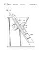
- FIG. 2is a front elevational view of a coin singulation and transport device according to an embodiment of the present invention
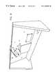
- FIG. 3is a partial exploded perspective view of the device of FIG. 2;
- FIG. 4is a side elevational view of the device of FIG. 2 partially in cross-section;
- FIG. 5is a cross-sectional view taken along line 5 — 5 of FIG. 2;
- FIGS. 6 A- 6 Care cross-sectional view corresponding to the view of FIG. 5, depicting coin movement into a coin pocket;
- FIG. 7Ais a cross-sectional view taken along line 7 A— 7 A of FIG. 2;
- FIG. 7Bis a cross-sectional view corresponding to the view of FIG. 7A, but showing the ramp in an up position;
- FIG. 8is a front perspective view of a coin singulation and transport device according to an embodiment of the present invention.
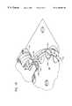
- FIG. 9is a rear perspective view of the device of FIG. 8;
- FIG. 10is a partial perspective view of a coin disk and ramp according to an embodiment of the present invention.
- FIG. 11is a block diagram of a control device showing inputs and outputs thereof according to an embodiment of the present invention.
- FIG. 12is a flow chart of a control process of a type which may be used in connection with an embodiment of the present invention.
- FIGS. 13A and 13Bare front and side elevational views of a sensor core usable in connection with an embodiment of the present invention.
- FIGS. 14A and 14Bare a block diagram of functional components of a sensor circuit, usable in connection with an embodiment of the present invention.
- FIG. 1depicts one manner of conceptualizing the stages or functions of a mass-input retail-level coin discriminating or counting device.
- a feed and clean system 104receives the mass of coins and preferably performs some form of cleaning to deal with non-coin objects, preferably feeding or moving the coins toward downstream components.
- a singulation component 106receives coins and outputs one or more streams of coins in a singulated “one at a time” fashion.
- a transport mechanism 108moves the coins, one at a time, past a sensor 110 , which senses one or more characteristics of the coins or other objects.
- the sensor 110may be configured to discriminate among different denominations of coins, discriminate coins of one country from those of another, and the like.
- a control device 116may provide control signals to various components such as by controlling the feed and clean system 104 to turn on and off (e.g., for regulating the flow of coins) and/or controlling the singulation system 106 to start, stop, or change speed.
- control device 116may provide control signals to the transport system, e.g., to initiate, stop or control the rate of transport.
- the diverter 112may receive its control signals either from the control device 116 or, in some cases, directly from the sensor 110 or hardware associated therewith 122 , bypassing the control unit 116 .
- One aspect of the present inventionis directed principally to the singulation and transport functions 106 , 108 , and preferably provides a single rotating disk which both singulates coins (or other objects) and transports the singulated objects past a sensor 110 .
- features or characteristics of one of the subsystemsmay affect the operation or selection of another system or function.
- a sensor system 110is provided which has predetermined limits on how quickly the coin may move past the sensor, such constraints will have an impact on the design and/or control of the transport system 108 .
- systems shown as separate systems in FIG. 1may be combined or may overlap.
- a single diskis used both for portions of the singulation function, the transport function and the diverter function.
- the fact that there may be some cleaning which occurs in the feed and clean system 104is not incompatible with providing some cleaning function in other systems such as the singulation system and/or the diverter system.
- the feed and clean system 104can include an input tray and/or slide similar to that described in U.S. Pat. No. 5,564,546 and/or a trommel or coin conditioning system similar to that described in Ser. No. PCT/US97/03136 and/or Ser. No. 60/012,964.
- a singulation system 106receives a mass of (possibly partially cleaned) coins and/or other objects fed to it by the feed and clean system 104 .
- the mass of coinsis placed in a bowl 212 with an open side 214 adjacent a rotatably mounted disk 216 .
- the disk 216is driven so as to rotate at about 60 to 72 RPM.
- the level of coins in the bowl 212 and/or the rate at which coins are introduced into the bowl 212is controlled either by upstream feed systems 104 , or by physical walls or barriers.
- openings (smaller than the smallest acceptable coin) adjacent the bottom of the bowl 212permit small debris to fall into a preferably removable trap 352 .
- the diskis mounted at an angle 218 to vertical 220 , (equal to the angle of the axis of rotation from horizontal) preferably between about zero and 45 degrees (more preferably between about 10 degrees and about 15 degrees, and even more preferably about 15 degrees).
- Disk 216is provided with one or more recessed areas or pockets 224 a through 224 l .
- the pocketsare U-shaped, and have a diameter 226 sufficient to accommodate, and preferably substantially equal to, the diameter of the largest coin which can be accepted.
- the pocketswill have a diameter 226 of about 1.1 inches (about 28 mm), in order to accommodate the U.S. fifty-cent piece.
- the disk 216is rotatably mounted in an opening 228 formed on a plate 230 .
- the opening 228provides a flange 232 positioned behind the perimeter or edge of the rear surface of the disk 216 .
- the edge of the disk 216is beveled 234 (FIG. 5 ), which may help prevent items such as rubber bands from being lodged between the rim of the disk 216 and the edge of the plate 230 or flange 232 , eventually slowing or braking the disk 216 .
- the mass of coinswill reside near the bottom of the bowl.
- the cumulative effect of the mass of coinsis believed to lead to a tendency to deflect the bottom edge of the disk 216 in a direction 618 towards the flange 232 .
- the disk 216can rub against the flange 232 , creating a braking effect.
- sufficient clearancesuch as about 0.03 inch (about 0.75 mm) 622 , is preferably provided to avoid this effect.
- spaces and cracks in the devicewhich might otherwise be large enough to receive or jam a coin are filled with a foam or other material to avoid jamming or loss of coins.
- the flange 232may be provided with foam rubber or other sealant over much of its extent, such foam rubber is preferably absent from the coin pickup region 362 .
- the bottom surface of the pockets 224are provided with ribs or ridges 238 ( a-e ) which preferably extend along an axis 240 (FIG. 2) at an angle 242 , with respect to the disk radius 244 , between about 40 degrees and about 50 degrees, preferably about 45 degrees.
- the pockets 224have a depth 227 which is less than the thickness of the thinnest coin to be accepted by the device (where the depth of the pocket 216 is calculated from the outer surface of the disk to the tops of the ridges 238 a , 238 b , 238 c , as shown in FIG. 5 ).
- the thinnest U.S. coinis a U.S. dime
- the depth 227 of the pockets 224are preferably about 0.06 inches (about 1.5 mm).
- the depth of the pocketis sufficiently shallow that it does not contain two stacked coins of the thinnest denomination (such as dimes, in the case of U.S. coins).
- the edges of the pocketsare relatively sharp, such as providing an edge radius of about 0.001 inch (about 0.025 mm) or less.
- the disk 216has an overall thickness 264 of about 0.125 inches (about 3 millimeters), and a diameter 266 of about 7 inches (about 18 centimeters).
- the size of the disk 216should be sufficiently small to result in a loaded mass which is small enough not to overload the motor 268 at the desired rotation rate (as described below), but the disk should have sufficient thickness 264 to avoid an undesirable degree of deflection of the disk 216 (such as may result in friction braking from contact with the flange 232 ).
- the diskshould provide enough room to position the pockets 224 at a radius 244 from the axis of rotation 272 to achieve the desired throughput (e.g., as measured by the rate of coins transported past the sensor), and the desired influence (or lack thereof) of inertial or centrifugal force on the coins in the pockets (as described below).
- the deviceis able to acheive, with fully-loaded pockets, a throughput of at least about 500 coins per minute, preferably about 600 coins per minute, more preferably 700 coins per minute and even more preferably, at least about 850 coins per minute.
- the maximum acheivable coin throughput(for a device which has a single rotating disk) will be 720 coins per minute, and the maximum acheivable throughput at a rate of 72 RPM will be 864 coins per minute.
- throughputmay always be increased by increasing the rotation rate, it has been found that, within certain windows, throughput of counted or discriminated coins is increased by decreasing the rotation rate (e.g., from about 72 RPM to about 60 RPM), because this tends to facilitate coin pickup (i.e., positioning coins in pockets), reducing the number of empty pockets.
- the disk 216is formed from G-10 epoxy board of the type commonly used for printed circuit boards (PCBs).
- the disk 216can also be formed of numerous other materials, including metals, reinforced metals, ceramics, reinforced ceramics, metal disks with ceramic inserts, plastics (such as that sold under the trade name of Delrin), fiberglass, resins, reinforced resins, and the like.
- all or a portion (such as annular portion 274 ) of the pocketed surface of the disk, and particularly the pocket edges,is covered with a wear-resistant material such as silicon carbide or other ceramic coating.
- the disk 216is positioned concentrically in opening 228 by coupling (e.g., via screws 276 a , 276 b , 276 c ) to the output shaft 278 of concentrically-mounted motor 268 .
- Motor 268may be concentrically mounted in a number of fashions, e.g., as depicted in FIG. 9 .
- the depicted embodimentshows the disk 216 directly mounted to the output shaft 278 of the motor 268 , other types of transmissions are possible, including belt-drive transmissions, gear transmissions, and the like.
- the motor 268provides a relatively vibration-free and very smooth motion.
- motorssuch as an alternating current (AC) motor, a stepper motor, and the like.
- ACalternating current
- SS60Model SS60, available from Oriental Motors.
- timing disk 282is also mounted concentrically with the axis of rotation 272 .
- timing disk 282has a circular concentric opening of a size allowing the disk to be press-fit onto the output shaft 278 of the motor 268 .
- the timing disk 282includes 12 evenly spaced concentric holes 286 with a (preferably infrared) light source 288 and detector 292 mounted in a stationary position with respect to the plate 230 , on opposite sides of the timing disk 282 , radially aligned with the holes 286 .
- the detector 292will detect light from the source 282 as each hole 286 rotates into alignment with the detector 292 .
- a signal indicative of such light detectionmay be communicated (e.g., via a wire or a wireless link) to a control device, as described more thoroughly below.
- the timing disk 282contains 12 evenly-spaced holes 286 , each one corresponding to one of the 12 pockets in the disk 216 to provide, upon each rotation of the disk 216 , twelve pulses at detector 292 , each corresponding to one of the pockets.
- phase of detected light pulseswith respect to, e.g., the pocket positions of the disk 216 , may be adjusted by rotating the press-fit timing disk 282 with respect to the output shaft 278 about the common axis 272 .
- Other manners of detecting the rotational position or rate of the disk 216can be provided, as will be apparent to those with skill in the art, such as placing or coupling optically, mechanically or magnetically detectable marks or sources on the disk 216 or the motor shaft 278 .
- one or more fingers 314 , 316are positioned adjacent the pocketed surface of the disk 216 in approximately the one o'clock and three o'clock positions, and extending across at least a portion of, and preferably beyond, the annular region occupied by the pockets 224 .
- the fingers 314 , 316are provided to assist in repositioning coins or other objects which are not properly seated in pockets, such as coins which may have adhered to the front surface of the disk 216 or to other coins.
- other devices for moving improperly-positioned coins or other objectscan be used, such as rigid bars, brushes, levers, and the like.
- the fingers 314 , 316are made of stainless steel, preferably with sufficient strength to move the coins as desired, but with sufficient resiliency to deflect so as to avoid jamming.
- a stripper plate 366is positioned on the left portion of the bowl 212 (in the view of FIG. 3) to prevent coins or other objects which may have adhered to the surface of the disk, without residing in pockets, from exiting the bowl in a manner so as to cause a jam or to move to a location other than an acceptable location (i.e., reject chute 342 , acceptable coin chute 344 , or trap 352 ).
- the depicted vertical position of the stripper wall 366can be determined empirically, and has been found to significantly affect efficiency of the device.
- One or more coin sensors or discriminators 312are provided in such a position as to permit detection or discrimination of coins or other objects in the pockets 224 .
- an electromagnetic discriminator 312is positioned adjacent the pocketed surface of the disk 216 approximately in the eleven o'clock position in the view of FIG. 2 .
- the plates 230are formed of aluminum.
- the discriminator 312is mounted to permit adjustment of the position of the sensor in a radial direction 314 .
- the discriminator 312is configured to provide and output signals of a nature which permits automatic coin discrimination, preferably permitting at least discrimination of coins from non-coin objects and, more preferably, also permitting discrimination from non-acceptable coins (e.g., coins of one or more predetermined countries, from coins of other countries) and, even more preferably, permitting discrimination among various coin denominations (e.g., permitting discrimination of U.S.
- output from the discriminator 312is provided via a communication link such as a wire or, a wireless communication link (such as an infra red (IR) communication link, and the like, not shown) to a control device and/or counting device.
- a communication linksuch as a wire or, a wireless communication link (such as an infra red (IR) communication link, and the like, not shown) to a control device and/or counting device.
- IRinfra red
- detectors or discriminatorscan be used, including electromagnetic, magnetic, optical, acoustic, capacitive, and the like.
- the detectorcan be of the type described in U.S. patent application Ser. No. 08/807,046, which is a continuing application claiming priority in U.S. patent application Ser. No. 08/672,639 filed Jun. 28, 1996, both commonly assigned herewith and incorporated herein by reference, and/or U.S. patent application Ser. No. 08/883,780 filed on even date herewith, commonly assigned herewith and incorporated herein by reference.
- the senoruses a magnetic core 2802 (FIGS. 13A, 13 B) with low-frequency 2804 and high frequency 2806 a and 2806 b windings on the core.
- the core 2802in the depicted embodiment, is generally U-shaped with a lower annular, semicircular, square cross-sectioned portion 2808 and an upper portion defining two spaced-apart legs 2812 a , 2812 b .
- the facing surfaces 2822 a, b of the legs 2812 a, bare, in the depicted embodiment, substantially parallel and planar and are spaced apart a distance 2824 of about 0.3 inches (about 8 mm).
- the upper leg 2812 a of the coreis spaced from the lower leg 2812 b of the core by the inter-face gap 2824 to define a space for coin passage through the inter-leg gap.
- the core 2802may be viewed as having the shape of a capped torroid with extended legs 2812 a , 2812 b with parallel faces 2822 a, b .
- the extended facesprovide relative insensitivity to the vertical 2828 or horizontal 2832 position of coins therein so as to provide useful data regardless of moderate coin bounce and/or wobble as a coin passes through the gap 2824 .
- the extended legsprovide tolerance to system variation in coin positional registration that can result from, e.g., the action of gravity, friction and/or inertial forces on the coin.
- a low frequency winding 2804is positioned at the bottom of the semicircular portion 2808 and the high frequency winding is positioned on each leg 2806 a, b of the semicircular portion.
- the low frequency windingis configured to have an inductance (in the driving and detection circuitry described below) of about 4.0 milliHenrys and the high frequency winding 2806 a, b to have an inductance of about 40 microHenrys. These inductance values are measured in the low frequency winding with the high frequency winding open and measured in the high frequency winding with the low frequency winding shorted together.
- the senor or transducerprovides a portion of a phase locked loop (PLL) part of a circuit, which is maintained at a substantially constant frequency.
- PLLphase locked loop
- VCOVoltage Controlled Oscillator
- This VCO input voltageis the signal used to indicate change of inductance in this circuit.
- Amplitude measurement of the sinusoidal oscillator waveformis accomplished 2914 a, b by demodulating the signal with a negative peak detecting circuit, and measuring the difference between this value and the DC reference voltage at which the sinusoidal signal is centered.
- a parametersuch as the size or diameter of the coin or object is indicated by a change in inductance, due to the passage of the coin, and the conductivity of the coin or object is (inversely) related to the energy loss (which may be indicated by the quality factor or “Q.”) while a signal related to change in inductance, and thus to coin diameter is termed “D.”
- the D signalmay not be purely proportional to diameter (e.g., being at least somewhat influenced by the value of Q) and Q may not be strictly and linearly proportional to conductance (e.g., being somewhat influenced by coin diameter) there is a sufficient relationship between signal D and coin diameter and between signal Q and conductance that these signals, when properly analyzed, can serve as a basis for coin discrimination.
- the low frequency coil leadsare provided to a low frequency PLL 2902 a and the high frequency leads are provided to high frequency PLL 2902 a, b .
- the coin sensor phase locked loopwhich includes the sensor or transducer 312 , maintains a constant frequency and responds to the presence of a coin in the gap 2824 by a change in the oscillator signal amplitude and a change in the PLL error voltage.
- the winding signals(2 each for high frequency and low frequency channels) are conditioned at 2904 and sent to an analog-to-digital (A/D) converter 2906 .
- the A/D convertersamples and digitizes the analog signals and passes the information e.g. to a microcontroller.
- the PLL error voltageis filtered and conditioned for conversion to digital data.
- the oscillator signalis filtered, demodulated, then conditioned for conversion to digital data. Since these signals are generated by two PLL circuits (high and low frequency), four signals result as the “signature” for identifying coins.
- the different frequenciesare used. Without wishing to be bound by any theory, it is believed use of different frequencies facilitates the probing of different depths in the thickness of the coin. It is believed this method is effective because, in terms of the interaction between a coin and a magnetic field, the frequency of a variable magnetic field defines a “skin depth,” which is the effective depth of the portion of the coin or other object which interacts with the variable magnetic field.
- a first frequencyis provided which is relatively low to provide for a larger skin depth, and thus interaction with the core of the coin or other object, and a second, higher frequency is provided, high enough to result in a skin depth substantially less than the thickness of the coin.
- the sensoris able to provide four parameters: core conductivity; cladding or coating conductivity; core diameter; and cladding or coating diameter.
- core conductivitycladding or coating conductivity
- core diametercore diameter
- cladding or coating diametercore diameter
- the core and cladding diameterswill be similar, obtaining both measurements can be useful since there may be some coupling of the Q and D signals, and it may be helpful in defeating certain types of counterfeit coin schemes, such as so-called cloaking schemes.
- the low-frequency skin depthis greater than the thickness of the plating or lamination, and the high frequency skin depth is less than, or about equal to, the plating or lamination thickness (or the range of lamination depths, for the anticipated coin population).
- the frequency which is chosendepends on the characteristics of the coins or other objects expected to be input.
- the low frequencyis between about 50 KHz and about 500 KHz, preferably about 200 KHz and the high frequency is between about 0.5 MHZ and about 10 MHZ, preferably about 2 MHz.
- results of the coin discrimination analysisare used in controlling the path of coins.
- a controllably-movable ramp 322is positioned adjacent the pocketed surface of the disk 216 in such a manner as to move, in response to activation of a solenoid 324 , between a down position (FIG. 7A) and an up position (FIG. 7 B).
- the ramp 322tapers toward the leading edge 328 to a finger 332 of a size and shape such that it can fit into the annular groove 246 .
- the ramp 322is preferably formed of full hard stainless steel to provide for sufficient durability.
- the ramp 322has a thickness of about 0.01 inches (about 0.25 mm) and is otherwise configured such that the leading edge 328 of the ramp 322 , when the ramp is in the down position (FIG. 7 A), is below the coin-contact plane 334 (see FIG. 5) of pockets 224 , to avoid contact between the leading edge of the ramp 328 and the leading edge of a coin 334 c in a pocket as the pocket moves past the ramp.
- the ramp 322is positioned in the down position (FIG.
- the coinfirst contacts the upper surface of the ramp 322 at a location 336 spaced from the leading edge, so that a direct collision between a coin leading-edge and the ramp leading-edge is avoided.
- the solenoidpreferably does not actively lift the coin, but, rather, the power to move the coin from a pocket is provided by the rotation of the disk.
- the tip of the ramp 322is positioned underneath the coin at the time the leading edge of the coin first contacts the upper surface of the ramp.
- the finger 322is positioned at approximately the nine o'clock position of the disk 216 .
- the ramp 322By positioning the ramp 322 at approximately the nine o'clock position, the diversion of the coins (after removal from the pockets) follows an approximately straight-line path. Furthermore, this position, in the depicted embodiment, provides sufficient time to analyze the data from the sensor 312 and control the ramp 322 . It is preferred, however, to generally minimize or reduce the amount of time between detection by sensor 312 and diversion by finger 322 , since this period represents the period of greatest opportunity for miscounts.
- a reject chute 342 and acceptable-coin chute 344are positioned with upper openings at approximately the eight o'clock position of the disk 216 .
- the lower opening 342 a of the reject chuteis formed as or positioned adjacent, a reject bin or container (not shown) for receiving rejected coins and/or rejected non-coin objects.
- coins or other objects diverted to the acceptable coin chute 344can be directed to either of two or more arms 344 a , 344 b by a diverter paddle 346 , which may be operated by a motor 348 to move between a first position 346 for diverting coin into one arm 344 b , and a second position 356 ′ for diverting coins into the other arm 344 a (e.g., when it has been sensed that the coin bin or bag connected to arm 344 b is full).
- the diverter or paddle 346is moved by an AC synchronous gear motor 348 , available from Houser, at a rate of about 30 RPM.
- the devicecan be configured either so that the ramp 322 moves to the down position to remove non-coin objects from the pockets (letting acceptable coins rotate past the ramp), or so that the ramp moves to the down position to remove acceptable-coins from the pockets (letting non-coin objects or non-acceptable coins rotate past the ramp). It is preferred to use the latter method, picking out good coins and letting non-coin objects and debris rotate past the ramp. This is because, the actual device (ramp) is operating on a recognized coin with known properties (e.g. size and weight) whereas attempting to divert non-coin objects would require the ramp to operate on an object of unknown size and shape.
- known propertiese.g. size and weight
- a system which diverts only valued coins to an acceptance bin or bagreduces or eliminates non-coin debris that, e.g., can jam in post-process equipment (equipment that processes coins from the bins or bags after they are removed from the coin-handling machine) reducing post-processing costs.
- the solenoid 324must be a solenoid which is sufficiently fast-acting to move the ramp between the up position and the down position in a period no greater than that required to rotate the disk 216 through an angle 348 defined by the space between adjacent pockets. In one embodiment, the time required to move the ramp to the down position is about five milliseconds. Although a solenoid 324 has been found to be sufficiently quick and reliable for the described function, it is also possible to use other devices for moving the ramp, such as a stepper motor. One example of a solenoid which can be used for this purpose is manufactured by Guardian.
- FIG. 11is a block diagram showing the relationship of a computer or other controller 810 to various input devices (such as the optical detector 292 , sensor 312 , and “hopper full sensor” 812 ), and the output signals to controlled components (such as the solenoid 324 , a motor 268 , and/or diverter flapper 346 ), according to one embodiment of the present invention.
- input devicessuch as the optical detector 292 , sensor 312 , and “hopper full sensor” 812
- controlled componentssuch as the solenoid 324 , a motor 268 , and/or diverter flapper 346
- FIG. 12is a flow chart of a procedure, preferably a computer-implemented procedure, for controlling a device according to an embodiment of the present invention, which may involve software being run on the computer or other controller 810 .
- FIG. 12illustrates only those portions of software for the singulation and transport functions and does not illustrate, for example, software for evaluating absence/presence, type and/or denomination of coins or other objects.
- a mass or plurality of coinsis fed, by a feed system 104 , into the bowl 212 .
- the control systemwill reside in an idle state or loop 912 until the device has sensed that objects are being fed into the bowl 914 .
- the control systemwill cause the motor to start in order to rotate the disk 216 and begin singulating and transporting coins.
- the systemwill continuously monitor for detection of a jam 918 or detection of a “no more coins” result 922 .
- the devicereacts to detection of a jam or other undesired stoppage of the rotation of the disk 216 in such a manner as to tend to clear the jam or other problem.
- One characteristic of the preferred AC synchronous motoris that the motor tends to rapidly oscillate or vibrate, at about 60 hertz, when the drive shaft is jammed or otherwise stopped. This oscillatory movement tends to assist in clearing jams.
- the controllerwill control the motor to undergo a “shake” mode 924 , alternately moving the disk about 5 to 10 degrees in forward 353 and reverse 354 directions, with a relatively short period (e.g., about 200 milliseconds).
- a “shake” mode 924alternately moving the disk about 5 to 10 degrees in forward 353 and reverse 354 directions, with a relatively short period (e.g., about 200 milliseconds).
- Other devices for assisting in dejamminginclude providing streams or jets of air (which may be relatively high pressure, short duration jets or streams, e.g., provided from a large reservoir of compressed air).
- the controllerwhen the sensor or discriminator 312 fails to detect any coins in any pockets for a predetermined period of time (such as 5 seconds) 922 , the controller causes the motor to rotate the disk 216 in a reverse direction 926 (clockwise in the view of FIG. 2) 354 , preferably, at about the same rate of 60 to 72 RPM.
- a reverse direction 926clockwise in the view of FIG. 2 354
- items contained in the bowle.g., unacceptable coins, non-coin objects, or coins which were not captured by pockets
- are carried clockwise out of the bowl 312typically about 10 to 15 degrees, before being ejected by inertia from the disk and moving into the reject chute.
- the deviceis configured to urge the coins which reside in the bowl toward a position such that the plane of the coin is parallel to the plane of the disk.
- the lower portion of the bowl 212is configured to provide a trough 612 extending somewhat below the lower edge of the disk 212 .
- a shoulder region 614is positioned above the trough, and provides a “waterfall” effect such that, as coins slide down the wall of the bowl 212 under the influence of gravity, upon reaching the shoulder 614 the coins tend to flip or rotate, as shown in FIG. 6B, with the upper edge gaining a rotational momentum 616 , tending to carry the coin in the desired direction, parallel to the disk 212 for engagement or “pickup” by a coin pocket, as depicted in FIG. 6 C.
- the force of gravityincludes a radially outward component, which tends to reinforce the radially outward centrifugal force on the coins, positioning the coins in a radially-outward portion of the pockets.
- the force of gravitytakes on a radially-inward component. Accordingly, in the position between about the one o'clock position and the eleven o'clock position, gravity forces begin to outweigh centrifugal (inertia) forces, and the coins tend to move from a radially outward position 334 l towards a radially inward position 334 b .
- the sensor 312When the sensor 312 is of a type which is sensitive to the radial position of the coin with respect to the sensor, it is believed useful to facilitate this movement to the radially-inward position, so that by the time the coins reach the sensor, they are registered in the pockets in a known radial position (preferably an inmost radial position) with respect to the sensor 312 .
- One manner of facilitating this movementis to provide the ridges 238 a , 238 b , 238 c , described above, which tends to minimize the area of contact between the coins and the disk, also minimizing friction and surface tension, particularly as coins slide within the pocket toward the desired registered position. This feature has been found to be especially useful when the coins are wet or are coated with an adhesive or sticky substance.
- Another feature that reduces or minimizes surface contact between the coins and the diskcan be used.
- the depicted embodimentuses gravity advantageously for registering the coins in the desired radial position within the pockets
- other manners of registering the coins within the pocketsmay also be used, such as by providing for a relatively fast RPM and/or large diameter of the disk, (relying on centrifugal (inertia) forces, in order to register the coins to the radially outward position), or providing for additional fingers or other mechanical guiding devices.
- a relatively shallow angletends to lead to increased difficulty of stripping multiple or unwanted coins from pockets, which may lead to jamming.
- Another approach to addressing the issues of coin positional registrationis to configure, locate and/or position system sensors such that they are tolerant of coin positional variation.
- the pocketwill contain, at most, a single coin.
- the sensordetects one or more characteristics of the coin (such as a characteristic indicative of its conductivity, permissivity, diameter, thickness, plating or composition and the like).
- Data from the sensor 312is provided to the computer 810 , as shown in FIG. 11, and, in the preferred embodiment, is analyzed in order to determine whether the object in the pocket (if any) should be removed from the pocket by the ramp 322 or allowed to rotate past the ramp.
- a number of processescan be used for analyzing data to make this determination.
- the computer or other controller 810outputs a signal 814 to the solenoid 324 to control whether the solenoid will position the ramp 322 in the up position or down position.
- the controllerprovides a “ramp down” signal 934 to the solenoid 324 at a time after the trailing edge of the preceding pocket has rotated past the leading edge of the ramp 332 , and before the leading edge of the target pocket (i.e., the one containing the accepted coin) is rotated to the position of the leading edge of the ramp 332 .
- thisis achieved by activating the solenoid 324 a predetermined period (such as about 40 milliseconds) after a pulse corresponding to the target pocket is detected by the detector 292 .
- the amount of time allowed for moving the ramp to down positioni.e., the amount of time for rotation through angle 348 , is about 10 milliseconds.
- the deviceis believed to operate with reasonable reliability when the downtime tolerance is about one to two milliseconds.
- the solenoid 324deactivates in order to raise the ramp 322 to the up position 322 ′, 936 at a time such that the leading edge of the ramp 322 will be assured of clearing the leading edge or a coin or other object 334 c , in the next pocket 224 c , should the object be an unacceptable object.
- Coins or other objects which are not diverted out of a pocket by the ramp 322are rotated past the position of the ramp and ejected, by their own inertia, from the pocket as the pocket reaches the position of the reject chute 342 .
- the sensor/controllercontrols the solenoid 324 so that, after moving downward to remove the coin or other object from the first of the two successive pockets, the ramp is maintained in one down position as the first pocket rotates past the position of the ramp leading edge and the second of the two successive pockets rotates past the position of the ramp leading edge, thus causing ejection of the second of the two successive coins.
- a similarly-sustained down position of the rampcan be used for three or more successive pockets which have acceptable coins, which can reduce the amount of wear from repeated cycling.
- the devicecan be configured so that whenever the ramp is moved to the down position to remove a coin or other object from a pocket, thereafter the solenoid is always deactivated so as to initiate lifting the ramp toward the up position before the next successive pocket rotates to the ramp leading edge position.
- the solenoidis always deactivated so as to initiate lifting the ramp toward the up position before the next successive pocket rotates to the ramp leading edge position.
- one operable mode of usehas been to initiate downward movement of the ramp about 5 milliseconds following detection of a pulse corresponding to the first pocket and to initiate upward movement of the ramp about 30 milliseconds after initiation of the downward movement. It has been found that an operable mode can be achieved if the phase for the optical disk is adjusted such that a pulse, corresponding to a particular pocket is generated about 5 milliseconds after the leading edge of such pocket first reaches the center line of the detector/discriminator 312 .
- the optical detector 292By judiciously positioning the optical detector 292 and adjusting the phase, it is possible to configure an operable device in which the optical pulse corresponding to a particular pocket is always the next optical pulse following an event (such as arrival of a pocket at a detector) and/or so that when down movement of a ramp is desired, proper timing is achieved by generating a signal which causes the solenoid 324 to be activated upon the occurrence of the next pulse from the optical detector 292 .
- an eventsuch as arrival of a pocket at a detector
- the coins or other objects to be sensedare moved in a positive-drive fashion past the sensor (as opposed to relying on gravity-driven, ramped, or other passive movement systems), creating a more predictable rate of movement past the sensor and the diverting mechanism, which, depending e.g. on the type of sensor used, can result in more accurate sensing and diversion of valued coins.
- a further advantage of the disclosed deviceis that the coins are contained, positively positioned and propelled past the sensor and diverted, reducing or minimizing the opportunity for losing or inaccurately diverting a coin. Such position propulsion provides the opportunity for faster throughput speeds than a passive, e.g. fully gravity-driven, system.
- a powered system instrumented with appropriate sensors and controlled with softwarecan achieve self-recovery from jams, reducing field downtime and several costs.
- the relatively uncomplicated configuration of the devicereduces the number of locations where coins and/or non-coin debris can lodge, potentially causing machine jams.
- the signal output by the sensorcan be used to ascertain the diameter of the coin or other object (such as by multiplying the duration of the signal between the leading edge of the coin and the trailing edge of the coin times the known velocity of the coin past the sensor).
- the positive (or near-positive) control of the coinmeans that the coin is contained, preferably for the entire journey from pick-up past the sensor.
- the position of the coinis thus known, within a certain envelope, at all times during such containment, resulting in decreased complexity (e.g. of sensing and diverting hardware and software) and increased accuracy.
- Positive controlprovides more stability for the coins, giving the possibility of higher processing speeds, for the same level of stability or accuracy.
- the present configurationreduces or eliminates the potential for coins to leave the intended path (to “fall off the rail”) before, during and after their passage past the sensor.
- the present inventionprovides for a relatively small number of parts to achieve the singulation, transport and diversion functions, and at a relatively low cost.
- the low part countalso assists in providing the device as a low maintenance device.
- the depicted configuration with integrated hopper and sensor (and diverter)provides a relatively simple assembly and disassembly for lower fabrication and operating costs, and a low part count for low manufactured cost.
- the designaccommodates a variety of sensor configurations including a gapped plate and a gapped torroid configuration.
- the depicted flat diskis relatively inexpensive to manufacture and simple and inexpensive to service and requires little adjustment or maintenance. It is believed that, previously, flat disks were considered difficult to properly load and thus a poor choice.
- the bi-directional ramp at the bottom of the hopperassists in properly loading all coins into the disk pockets, even though the disk is flat.
- the actuate-to-accept configuration of the diverterhelps ensure safe and error free operation. Active acceptance increases accuracy because there is no need to try to hit or strike unrecognized and potentially odd-shaped debris and materials with a solenoid or pin. Actuate-to-accept configuration allows the machine to return unrecognized or unaccepted items, material or debris to the user, avoiding placing debris in an “acceptance” bin.
- the diverter configurationpermits the use of a stepper motor for actuation of the diverter, rather than a solenoid, which offers superior reliability.
- the pocketsare provided with a circular or “U” shape, other shapes could be provided, e.g. to assist in registering the coins with respect to the sensor.
- the pocket edgecan be shaped so that the portion of the pocket edge which is at the bottom as the pocket approaches the sensor (approximately the eleven o'clock position) has, for example, a “V” shape to help the coin register under the sensor.
- an activatable rampis used to divert or lift coins out of pockets
- other devices for removing coins or other objects from pocketscan be used.
- coinsmay be removed by striking the opposite or rear surface (i.e. the surface opposite the surface which has the coin pockets) of the disk in the region of the pockets (preferably thin-floored pockets, such as 0.01 to 0.015 inch thick), with a quick (e.g., ten millisecond) pulse.
- a quicke.g., ten millisecond
- devicesmay be provided to impart vibration to the bowl of the coins within the bowl, such as by positioning protrusions on the disk 216 , configured to periodically strike stationary surfaces as the disks rotate, to impart an impact or vibration.
- a devicewhich has two or more rotating pocketed disks or other coin singulation devices, such that the stream of input coins are divided among two or more singulators, rails, and/or sensors or the like, e.g. to acheive a higher throughput.
- the described sensorcan sense passive coins or other objects, it is possible to use the present invention in connection with a sensor which senses an active or reflective object.
- coins or other objectsmay be provided with circuity or other devices configured to broadcast, transpond or reflect signals such as radio-frequency (RF) electromagnetic signals.
- RFradio-frequency
- a sensorcan be used which senses such Rf signals to detect, discriminate and/or identify coins or other objects.
Landscapes
- Physics & Mathematics (AREA)
- General Physics & Mathematics (AREA)
- Testing Of Coins (AREA)
Abstract
Description
Claims (26)
Priority Applications (1)
| Application Number | Priority Date | Filing Date | Title |
|---|---|---|---|
| US08/883,655US6168001B1 (en) | 1997-06-27 | 1997-06-27 | Positive drive coin discrimination apparatus and method |
Applications Claiming Priority (1)
| Application Number | Priority Date | Filing Date | Title |
|---|---|---|---|
| US08/883,655US6168001B1 (en) | 1997-06-27 | 1997-06-27 | Positive drive coin discrimination apparatus and method |
Publications (1)
| Publication Number | Publication Date |
|---|---|
| US6168001B1true US6168001B1 (en) | 2001-01-02 |
Family
ID=25383049
Family Applications (1)
| Application Number | Title | Priority Date | Filing Date |
|---|---|---|---|
| US08/883,655Expired - LifetimeUS6168001B1 (en) | 1997-06-27 | 1997-06-27 | Positive drive coin discrimination apparatus and method |
Country Status (1)
| Country | Link |
|---|---|
| US (1) | US6168001B1 (en) |
Cited By (58)
| Publication number | Priority date | Publication date | Assignee | Title |
|---|---|---|---|---|
| US6383070B1 (en)* | 1999-04-22 | 2002-05-07 | Aruze Co., Ltd. | Coin-sending device |
| US20020126885A1 (en)* | 1996-05-13 | 2002-09-12 | Mennie Douglas U. | Automatic funds processing system |
| US6602125B2 (en) | 2001-05-04 | 2003-08-05 | Coinstar, Inc. | Automatic coin input tray for a self-service coin-counting machine |
| US6601463B2 (en)* | 2002-01-03 | 2003-08-05 | Coin Acceptors, Inc. | Device for determining a level of objects in a hopper |
| US20040255026A1 (en)* | 2003-06-11 | 2004-12-16 | International Business Machines Corporation | Apparatus and method to dynamically allocate bandwidth in a data storage and retrieval system |
| US20050280212A1 (en)* | 2002-06-05 | 2005-12-22 | Ernst Blaha | Counter sorting device |
| US20060054457A1 (en)* | 2002-06-14 | 2006-03-16 | Cummins-Allison Corp. | Foreign object removal system for a coin processing device |
| US20060175176A1 (en)* | 2005-02-10 | 2006-08-10 | Blake John R | Method and apparatus for varying coin-processing machine receptacle limits |
| US20070010186A1 (en)* | 2003-12-02 | 2007-01-11 | Jerry Karlson | Coin handling apparatus with means for deflecting non-separated valid coins |
| US20070010185A1 (en)* | 2003-12-02 | 2007-01-11 | Jerry Karlsson | Coin handling apparatus having slidably displaceable housing parts |
| US20070062783A1 (en)* | 2005-09-17 | 2007-03-22 | Hill Timothy W | Coin handling equipment |
| US20070099553A1 (en)* | 2002-06-05 | 2007-05-03 | Shuffle Master Gmbh & Co Kg | Chip stack cutter devices for displacing chips in a chip stack and chip-stacking apparatuses including such cutter devices, and related methods |
| US20070187485A1 (en)* | 2006-02-10 | 2007-08-16 | Aas Per C | Cash handling |
| US20080039004A1 (en)* | 2006-08-08 | 2008-02-14 | String Gregory F | Coin Machine with Self-Cleaning Intake Hopper and Related Method |
| US20090087076A1 (en)* | 2000-02-11 | 2009-04-02 | Cummins-Allison Corp. | System and method for processing currency bills and tickets |
| US20090236201A1 (en)* | 1996-05-13 | 2009-09-24 | Blake John R | Apparatus, System and Method For Coin Exchange |
| US20090239459A1 (en)* | 2008-03-19 | 2009-09-24 | Cummins-Allison Corp. | Self Service Coin Processing Machines With EPOS Terminal And Method For Automated Payout Utilizing Same |
| US20100029188A1 (en)* | 2007-03-29 | 2010-02-04 | Glory Ltd. | Coin dispensing device and coin processing machine |
| US20100112923A1 (en)* | 2005-07-17 | 2010-05-06 | Timothy William Hill | Coin handling equipment |
| US20100230233A1 (en)* | 2003-02-03 | 2010-09-16 | Shuffle Master Gmbh & Co Kg | Apparatus for sorting articles |
| US7886890B2 (en) | 2002-06-14 | 2011-02-15 | Cummins-Allison Corp. | Coin redemption machine having gravity feed coin input tray and foreign object detection system |
| US20110105002A1 (en)* | 2009-11-02 | 2011-05-05 | Ernst Blaha | Chip Sorting Devices, Components Therefor and Methods of Ejecting Chips |
| US8023715B2 (en) | 1995-05-02 | 2011-09-20 | Cummins-Allison Corporation | Automatic currency processing system having ticket redemption module |
| US8042732B2 (en) | 2008-03-25 | 2011-10-25 | Cummins-Allison Corp. | Self service coin redemption card printer-dispenser |
| ITBO20100729A1 (en)* | 2010-12-10 | 2012-06-11 | Alberici S P A | DEVICE FOR DISCRIMINATING AND DELIVERING COINS |
| US8393455B2 (en) | 2003-03-12 | 2013-03-12 | Cummins-Allison Corp. | Coin processing device having a moveable coin receptacle station |
| USRE44252E1 (en) | 2002-01-10 | 2013-06-04 | Cummins-Allison Corp. | Coin redemption system |
| US8523641B2 (en) | 2004-09-15 | 2013-09-03 | Cummins-Allison Corp. | System, method and apparatus for automatically filling a coin cassette |
| US8545295B2 (en) | 2010-12-17 | 2013-10-01 | Cummins-Allison Corp. | Coin processing systems, methods and devices |
| US8559694B2 (en) | 2005-10-05 | 2013-10-15 | Cummins-Allison Corp. | Currency processing system with fitness detection |
| USRE44689E1 (en) | 2002-03-11 | 2014-01-07 | Cummins-Allison Corp. | Optical coin discrimination sensor and coin processing system using the same |
| US8959029B2 (en) | 2006-03-23 | 2015-02-17 | Cummins-Allison Corp | System, apparatus, and methods for currency processing control and redemption |
| US8967361B2 (en) | 2013-02-27 | 2015-03-03 | Outerwall Inc. | Coin counting and sorting machines |
| US9011214B2 (en) | 2013-03-28 | 2015-04-21 | Scan Coin, AB | Rim geometry of a coin sorting device |
| US9022841B2 (en) | 2013-05-08 | 2015-05-05 | Outerwall Inc. | Coin counting and/or sorting machines and associated systems and methods |
| US9036890B2 (en) | 2012-06-05 | 2015-05-19 | Outerwall Inc. | Optical coin discrimination systems and methods for use with consumer-operated kiosks and the like |
| US9070238B2 (en) | 2013-03-28 | 2015-06-30 | Scan Coin Ab | Module and apparatus |
| US9092924B1 (en) | 2012-08-31 | 2015-07-28 | Cummins-Allison Corp. | Disk-type coin processing unit with angled sorting head |
| US20150221154A1 (en)* | 2011-04-07 | 2015-08-06 | Wincor Nixdorf International Gmbh | Apparatus and method for sorting coins |
| EP2905755A1 (en) | 2014-02-10 | 2015-08-12 | Outerwall Inc. | Coin input apparatuses and associated methods and systems |
| US20150325071A1 (en)* | 2014-04-18 | 2015-11-12 | Gccm, Llc | Coin Processing Machine |
| US9430893B1 (en) | 2014-08-06 | 2016-08-30 | Cummins-Allison Corp. | Systems, methods and devices for managing rejected coins during coin processing |
| US9443367B2 (en) | 2014-01-17 | 2016-09-13 | Outerwall Inc. | Digital image coin discrimination for use with consumer-operated kiosks and the like |
| US9501885B1 (en) | 2014-07-09 | 2016-11-22 | Cummins-Allison Corp. | Systems, methods and devices for processing coins utilizing near-normal and high-angle of incidence lighting |
| US9508208B1 (en) | 2014-07-25 | 2016-11-29 | Cummins Allison Corp. | Systems, methods and devices for processing coins with linear array of coin imaging sensors |
| US9818249B1 (en) | 2002-09-04 | 2017-11-14 | Copilot Ventures Fund Iii Llc | Authentication method and system |
| US9875593B1 (en) | 2015-08-07 | 2018-01-23 | Cummins-Allison Corp. | Systems, methods and devices for coin processing and coin recycling |
| US9916713B1 (en) | 2014-07-09 | 2018-03-13 | Cummins-Allison Corp. | Systems, methods and devices for processing coins utilizing normal or near-normal and/or high-angle of incidence lighting |
| US9934640B2 (en) | 2004-09-15 | 2018-04-03 | Cummins-Allison Corp. | System, method and apparatus for repurposing currency |
| WO2018072802A1 (en)* | 2016-10-17 | 2018-04-26 | Ctcoin A/S | Compact automatic coin counter |
| US10089812B1 (en)* | 2014-11-11 | 2018-10-02 | Cummins-Allison Corp. | Systems, methods and devices for processing coins utilizing a multi-material coin sorting disk |
| US10096192B1 (en) | 2017-08-30 | 2018-10-09 | Shuffle Master Gmbh & Co Kg | Chip sorting devices and related assemblies and methods |
| US20180299297A1 (en)* | 2017-04-14 | 2018-10-18 | Hamilton Sundstrand Corporation | Position detection systems and methods |
| US10181234B2 (en) | 2016-10-18 | 2019-01-15 | Cummins-Allison Corp. | Coin sorting head and coin processing system using the same |
| US10255741B2 (en) | 2016-04-06 | 2019-04-09 | Shuffle Master Gmbh & Co Kg | Chip sorting devices and related assemblies, components and methods |
| US10679449B2 (en) | 2016-10-18 | 2020-06-09 | Cummins-Allison Corp. | Coin sorting head and coin processing system using the same |
| US10685523B1 (en) | 2014-07-09 | 2020-06-16 | Cummins-Allison Corp. | Systems, methods and devices for processing batches of coins utilizing coin imaging sensor assemblies |
| US11443581B2 (en)* | 2019-01-04 | 2022-09-13 | Cummins-Allison Corp. | Coin pad for coin processing system |
Citations (34)
| Publication number | Priority date | Publication date | Assignee | Title |
|---|---|---|---|---|
| US1234707A (en) | 1916-09-21 | 1917-07-24 | American Railways Equipment Company | Coin-ticket-registering fare-box. |
| US3297242A (en) | 1967-01-10 | Apparatus and method for handling coins | ||
| US3463171A (en) | 1966-10-06 | 1969-08-26 | Brecknell Dolman & Rogers Ltd | Apparatus for extracting and feeding coins stored in a bulk supply |
| US3599771A (en) | 1968-08-28 | 1971-08-17 | Adolf Hinterstocker | Coin testing device for comparing coin to be tested with a standard coin |
| GB1255492A (en) | 1968-02-29 | 1971-12-01 | Brecknell Dolman And Rogers Lt | Coin testing and accepting or rejecting devices |
| US3680566A (en) | 1969-09-22 | 1972-08-01 | Micro Magnetic Ind Inc | Bulk coin dispenser |
| US3965912A (en) | 1973-08-20 | 1976-06-29 | Standardwerk Eugen Reis Gmbh | Coin storing and transferring apparatus |
| US4059122A (en)* | 1973-02-10 | 1977-11-22 | Glory Kogyo Kabushiki Kaisha | Coin classifying and counting machine |
| US4111216A (en) | 1976-04-01 | 1978-09-05 | Systems And Technics S.A. | Centrifugal coin sorter |
| US4148331A (en) | 1977-06-10 | 1979-04-10 | Bally Manufacturing Corporation | Coin-agitating method and means for coin-counting and dispensing machines |
| US4184366A (en) | 1976-06-08 | 1980-01-22 | Butler Frederick R | Coin testing apparatus |
| US4398550A (en) | 1981-04-24 | 1983-08-16 | Standard Change-Makers, Inc. | Coin dispensing mechanism |
| US4471864A (en) | 1980-03-06 | 1984-09-18 | Duane Marshall | Slug rejector |
| US4556140A (en)* | 1982-08-06 | 1985-12-03 | Kabushiki Kaisha Universal | Method and apparatus for discriminating coins or bank notes |
| US4574824A (en) | 1984-07-10 | 1986-03-11 | Igt | Agitator for coin hopper |
| US4588712A (en) | 1984-03-08 | 1986-05-13 | Pierrel S.P.A. | (8S)-8-fluoroerythromycin derivatives, the process for the preparation thereof and the pharmaceutical compositions containing them |
| EP0209357A2 (en) | 1985-07-17 | 1987-01-21 | Kabushiki Kaisha Universal | Coin pay-out apparatus |
| US4733765A (en) | 1985-11-14 | 1988-03-29 | Kabushiki Kaisha Toshiba | Cash handling machine for handling mixtures of notes and coins introduced together |
| GB2198274A (en) | 1986-12-03 | 1988-06-08 | Entersword Limited | Coin dispensers |
| US4754862A (en) | 1985-01-04 | 1988-07-05 | Coin Controls Limited | Metallic article discriminator |
| JPH01307891A (en) | 1988-06-06 | 1989-12-12 | Hitachi Ltd | coin deposit device |
| US4960196A (en) | 1988-02-17 | 1990-10-02 | Mitsubishi Jukogyo Kabushiki Kaisha | Automatic toll collector |
| US4978322A (en) | 1989-02-13 | 1990-12-18 | International Game Technology | Coin wiper for escalator hopper |
| JPH0363795A (en) | 1989-08-01 | 1991-03-19 | Mitsubishi Heavy Ind Ltd | Automatic fare receiving device |
| US5098339A (en) | 1991-01-23 | 1992-03-24 | 7's Unlimited, Inc. | Coin feeding device |
| US5131885A (en) | 1991-03-19 | 1992-07-21 | Tetsuo Nakao | Coin separating and counting apparatus |
| US5167571A (en) | 1991-04-11 | 1992-12-01 | International Game Technology | Coin handling machine |
| US5254032A (en) | 1991-07-19 | 1993-10-19 | Asahi Seiko Kabushiki Kaisha | Coin feeding device |
| US5279404A (en) | 1988-12-29 | 1994-01-18 | Imonex Services Inc. | Coin counting and escrow system |
| US5285883A (en)* | 1992-03-11 | 1994-02-15 | Atoll Technology | Automatic payment device and method for recognizing coins |
| US5316120A (en) | 1990-09-05 | 1994-05-31 | Azkoyen Industrial, S.A. | Housing for coin selectors |
| US5326312A (en) | 1991-09-13 | 1994-07-05 | Boardwalk Regency Corp. | Coin/token dispensing unit |
| US5386902A (en) | 1991-07-31 | 1995-02-07 | Mars Incorporated | Coin routing gate |
| US5484334A (en) | 1994-04-01 | 1996-01-16 | Evdokimo; Allen J. | Coin handling apparatus with coin filter and improved coin interlock |
- 1997
- 1997-06-27USUS08/883,655patent/US6168001B1/ennot_activeExpired - Lifetime
Patent Citations (36)
| Publication number | Priority date | Publication date | Assignee | Title |
|---|---|---|---|---|
| US3297242A (en) | 1967-01-10 | Apparatus and method for handling coins | ||
| US1234707A (en) | 1916-09-21 | 1917-07-24 | American Railways Equipment Company | Coin-ticket-registering fare-box. |
| US3463171A (en) | 1966-10-06 | 1969-08-26 | Brecknell Dolman & Rogers Ltd | Apparatus for extracting and feeding coins stored in a bulk supply |
| GB1255492A (en) | 1968-02-29 | 1971-12-01 | Brecknell Dolman And Rogers Lt | Coin testing and accepting or rejecting devices |
| US3599771A (en) | 1968-08-28 | 1971-08-17 | Adolf Hinterstocker | Coin testing device for comparing coin to be tested with a standard coin |
| US3680566A (en) | 1969-09-22 | 1972-08-01 | Micro Magnetic Ind Inc | Bulk coin dispenser |
| US4059122A (en)* | 1973-02-10 | 1977-11-22 | Glory Kogyo Kabushiki Kaisha | Coin classifying and counting machine |
| US3965912A (en) | 1973-08-20 | 1976-06-29 | Standardwerk Eugen Reis Gmbh | Coin storing and transferring apparatus |
| US4111216A (en) | 1976-04-01 | 1978-09-05 | Systems And Technics S.A. | Centrifugal coin sorter |
| US4184366A (en) | 1976-06-08 | 1980-01-22 | Butler Frederick R | Coin testing apparatus |
| US4148331B1 (en) | 1977-06-10 | 1993-01-12 | Manufacturers Hanover Trust Co | |
| US4148331A (en) | 1977-06-10 | 1979-04-10 | Bally Manufacturing Corporation | Coin-agitating method and means for coin-counting and dispensing machines |
| US4471864A (en) | 1980-03-06 | 1984-09-18 | Duane Marshall | Slug rejector |
| US4398550A (en) | 1981-04-24 | 1983-08-16 | Standard Change-Makers, Inc. | Coin dispensing mechanism |
| US4556140A (en)* | 1982-08-06 | 1985-12-03 | Kabushiki Kaisha Universal | Method and apparatus for discriminating coins or bank notes |
| US4588712A (en) | 1984-03-08 | 1986-05-13 | Pierrel S.P.A. | (8S)-8-fluoroerythromycin derivatives, the process for the preparation thereof and the pharmaceutical compositions containing them |
| US4574824A (en) | 1984-07-10 | 1986-03-11 | Igt | Agitator for coin hopper |
| US4754862A (en) | 1985-01-04 | 1988-07-05 | Coin Controls Limited | Metallic article discriminator |
| EP0209357A2 (en) | 1985-07-17 | 1987-01-21 | Kabushiki Kaisha Universal | Coin pay-out apparatus |
| US4753625A (en)* | 1985-07-17 | 1988-06-28 | Kabushiki Kaisha Universal | Coin pay-out apparatus |
| US4733765A (en) | 1985-11-14 | 1988-03-29 | Kabushiki Kaisha Toshiba | Cash handling machine for handling mixtures of notes and coins introduced together |
| GB2198274A (en) | 1986-12-03 | 1988-06-08 | Entersword Limited | Coin dispensers |
| US4960196A (en) | 1988-02-17 | 1990-10-02 | Mitsubishi Jukogyo Kabushiki Kaisha | Automatic toll collector |
| JPH01307891A (en) | 1988-06-06 | 1989-12-12 | Hitachi Ltd | coin deposit device |
| US5279404A (en) | 1988-12-29 | 1994-01-18 | Imonex Services Inc. | Coin counting and escrow system |
| US4978322A (en) | 1989-02-13 | 1990-12-18 | International Game Technology | Coin wiper for escalator hopper |
| JPH0363795A (en) | 1989-08-01 | 1991-03-19 | Mitsubishi Heavy Ind Ltd | Automatic fare receiving device |
| US5316120A (en) | 1990-09-05 | 1994-05-31 | Azkoyen Industrial, S.A. | Housing for coin selectors |
| US5098339A (en) | 1991-01-23 | 1992-03-24 | 7's Unlimited, Inc. | Coin feeding device |
| US5131885A (en) | 1991-03-19 | 1992-07-21 | Tetsuo Nakao | Coin separating and counting apparatus |
| US5167571A (en) | 1991-04-11 | 1992-12-01 | International Game Technology | Coin handling machine |
| US5254032A (en) | 1991-07-19 | 1993-10-19 | Asahi Seiko Kabushiki Kaisha | Coin feeding device |
| US5386902A (en) | 1991-07-31 | 1995-02-07 | Mars Incorporated | Coin routing gate |
| US5326312A (en) | 1991-09-13 | 1994-07-05 | Boardwalk Regency Corp. | Coin/token dispensing unit |
| US5285883A (en)* | 1992-03-11 | 1994-02-15 | Atoll Technology | Automatic payment device and method for recognizing coins |
| US5484334A (en) | 1994-04-01 | 1996-01-16 | Evdokimo; Allen J. | Coin handling apparatus with coin filter and improved coin interlock |
Cited By (124)
| Publication number | Priority date | Publication date | Assignee | Title |
|---|---|---|---|---|
| US8023715B2 (en) | 1995-05-02 | 2011-09-20 | Cummins-Allison Corporation | Automatic currency processing system having ticket redemption module |
| US20090236201A1 (en)* | 1996-05-13 | 2009-09-24 | Blake John R | Apparatus, System and Method For Coin Exchange |
| US20020126885A1 (en)* | 1996-05-13 | 2002-09-12 | Mennie Douglas U. | Automatic funds processing system |
| US8229821B2 (en) | 1996-05-13 | 2012-07-24 | Cummins-Allison Corp. | Self-service currency exchange machine |
| US8443958B2 (en) | 1996-05-13 | 2013-05-21 | Cummins-Allison Corp. | Apparatus, system and method for coin exchange |
| US20110099105A1 (en)* | 1996-05-13 | 2011-04-28 | Cummins-Allison Corp. | Self-service currency exchange machine |
| US6383070B1 (en)* | 1999-04-22 | 2002-05-07 | Aruze Co., Ltd. | Coin-sending device |
| US9129271B2 (en) | 2000-02-11 | 2015-09-08 | Cummins-Allison Corp. | System and method for processing casino tickets |
| US8701857B2 (en) | 2000-02-11 | 2014-04-22 | Cummins-Allison Corp. | System and method for processing currency bills and tickets |
| US20090087076A1 (en)* | 2000-02-11 | 2009-04-02 | Cummins-Allison Corp. | System and method for processing currency bills and tickets |
| US8684160B2 (en) | 2000-04-28 | 2014-04-01 | Cummins-Allison Corp. | System and method for processing coins |
| US6602125B2 (en) | 2001-05-04 | 2003-08-05 | Coinstar, Inc. | Automatic coin input tray for a self-service coin-counting machine |
| US6601463B2 (en)* | 2002-01-03 | 2003-08-05 | Coin Acceptors, Inc. | Device for determining a level of objects in a hopper |
| USRE44252E1 (en) | 2002-01-10 | 2013-06-04 | Cummins-Allison Corp. | Coin redemption system |
| USRE44689E1 (en) | 2002-03-11 | 2014-01-07 | Cummins-Allison Corp. | Optical coin discrimination sensor and coin processing system using the same |
| US20070102330A1 (en)* | 2002-06-05 | 2007-05-10 | Shuffle Master Gmbh & Co Kg | Chip sorting device |
| US20080053876A1 (en)* | 2002-06-05 | 2008-03-06 | Shuffle Master Gmbh & Co Kg | Chip sorting and stacking devices |
| US8393942B2 (en) | 2002-06-05 | 2013-03-12 | Shuffle Master Gmbh & Co Kg | Methods for displacing chips in a chip stack |
| US8006847B2 (en)* | 2002-06-05 | 2011-08-30 | Shuffle Master Gmbh & Co Kg | Chip sorting device |
| US20110207390A1 (en)* | 2002-06-05 | 2011-08-25 | Ernst Blaha | Chip stack cutter devices for displacing chips in a chip stack and chip-stacking apparatuses including such cutter devices, and related methods |
| US7861868B2 (en) | 2002-06-05 | 2011-01-04 | Shuffle Master Gmbh & Co Kg | Chip sorting and stacking devices |
| US7992720B2 (en) | 2002-06-05 | 2011-08-09 | Shuffle Master Gmbh & Co Kg | Chip sorting device |
| US7934980B2 (en) | 2002-06-05 | 2011-05-03 | Shuffle Master Gmbh & Co Kg | Chip stack cutter devices for displacing chips in a chip stack and chip-stacking apparatuses including such cutter devices |
| US20070099553A1 (en)* | 2002-06-05 | 2007-05-03 | Shuffle Master Gmbh & Co Kg | Chip stack cutter devices for displacing chips in a chip stack and chip-stacking apparatuses including such cutter devices, and related methods |
| US20050280212A1 (en)* | 2002-06-05 | 2005-12-22 | Ernst Blaha | Counter sorting device |
| US20110005983A9 (en)* | 2002-06-05 | 2011-01-13 | Shuffle Master Gmbh & Co Kg | Chip sorting device |
| US20110001290A9 (en)* | 2002-06-05 | 2011-01-06 | Ernst Blaha | Counter sorting device |
| US7886890B2 (en) | 2002-06-14 | 2011-02-15 | Cummins-Allison Corp. | Coin redemption machine having gravity feed coin input tray and foreign object detection system |
| US20110098845A1 (en)* | 2002-06-14 | 2011-04-28 | Cummins-Allison Corp. | Coin redemption machine having gravity feed coin input tray and foreign object detection system |
| US7438172B2 (en) | 2002-06-14 | 2008-10-21 | Cummins-Allison Corp. | Foreign object removal system for a coin processing device |
| US8607957B2 (en) | 2002-06-14 | 2013-12-17 | Cummins-Allison Corp. | Coin redemption machine having gravity feed coin input tray and foreign object detection system |
| US20060054457A1 (en)* | 2002-06-14 | 2006-03-16 | Cummins-Allison Corp. | Foreign object removal system for a coin processing device |
| US9818249B1 (en) | 2002-09-04 | 2017-11-14 | Copilot Ventures Fund Iii Llc | Authentication method and system |
| US20160196707A1 (en)* | 2003-02-03 | 2016-07-07 | Shuffle Master Gmbh & Co Kg | Apparatus for receiving and sorting disks |
| US9330516B2 (en) | 2003-02-03 | 2016-05-03 | Shuffle Master Gmbh & Co Kg | Apparatus for receiving and sorting disks |
| US8678164B2 (en)* | 2003-02-03 | 2014-03-25 | Shuffle Master Gmbh & Co Kg | Apparatus for receiving and sorting disks |
| US10706656B2 (en) | 2003-02-03 | 2020-07-07 | Shuffle Master Gmbh & Co Kg | Methods and apparatus for receiving and sorting disks |
| US9589407B2 (en)* | 2003-02-03 | 2017-03-07 | Shuffle Master Gmbh & Co Kg | Apparatus for receiving and sorting disks |
| US9990792B2 (en) | 2003-02-03 | 2018-06-05 | Shuffle Master Gmbh & Co Kg | Methods and apparatus for receiving and sorting disks |
| US20100230233A1 (en)* | 2003-02-03 | 2010-09-16 | Shuffle Master Gmbh & Co Kg | Apparatus for sorting articles |
| US20130052925A1 (en)* | 2003-02-03 | 2013-02-28 | Peter Wolfgang DeRaedt | Apparatus for receiving and sorting disks |
| US8298052B2 (en) | 2003-02-03 | 2012-10-30 | Shuffle Master Gmbh & Co Kg | Apparatus for sorting articles |
| US8393455B2 (en) | 2003-03-12 | 2013-03-12 | Cummins-Allison Corp. | Coin processing device having a moveable coin receptacle station |
| US20040255026A1 (en)* | 2003-06-11 | 2004-12-16 | International Business Machines Corporation | Apparatus and method to dynamically allocate bandwidth in a data storage and retrieval system |
| US20070010185A1 (en)* | 2003-12-02 | 2007-01-11 | Jerry Karlsson | Coin handling apparatus having slidably displaceable housing parts |
| US20070010186A1 (en)* | 2003-12-02 | 2007-01-11 | Jerry Karlson | Coin handling apparatus with means for deflecting non-separated valid coins |
| US9934640B2 (en) | 2004-09-15 | 2018-04-03 | Cummins-Allison Corp. | System, method and apparatus for repurposing currency |
| US8523641B2 (en) | 2004-09-15 | 2013-09-03 | Cummins-Allison Corp. | System, method and apparatus for automatically filling a coin cassette |
| US20060175176A1 (en)* | 2005-02-10 | 2006-08-10 | Blake John R | Method and apparatus for varying coin-processing machine receptacle limits |
| US8684159B2 (en) | 2005-02-10 | 2014-04-01 | Cummins-Allison Corp. | Method and apparatus for varying coin-processing machine receptacle limits |
| US8602200B2 (en) | 2005-02-10 | 2013-12-10 | Cummins-Allison Corp. | Method and apparatus for varying coin-processing machine receptacle limits |
| US20100112923A1 (en)* | 2005-07-17 | 2010-05-06 | Timothy William Hill | Coin handling equipment |
| US8092284B2 (en) | 2005-07-17 | 2012-01-10 | Scan Coin Ab | Coin handling equipment |
| US7658668B2 (en) | 2005-09-17 | 2010-02-09 | Scan Coin Ab | Coin handling equipment |
| US20070062783A1 (en)* | 2005-09-17 | 2007-03-22 | Hill Timothy W | Coin handling equipment |
| US8559694B2 (en) | 2005-10-05 | 2013-10-15 | Cummins-Allison Corp. | Currency processing system with fitness detection |
| US20090108059A1 (en)* | 2006-02-10 | 2009-04-30 | Per Christian Aas | Cash handling |
| US20070187485A1 (en)* | 2006-02-10 | 2007-08-16 | Aas Per C | Cash handling |
| US8136723B2 (en) | 2006-02-10 | 2012-03-20 | Scan Coin Ab | Cash handling |
| US8959029B2 (en) | 2006-03-23 | 2015-02-17 | Cummins-Allison Corp | System, apparatus, and methods for currency processing control and redemption |
| WO2008021812A3 (en)* | 2006-08-08 | 2009-04-02 | Gregory F String | Coin machine with self-cleaning intake hopper and related method |
| US7735622B2 (en) | 2006-08-08 | 2010-06-15 | String Gregory F | Coin machine with self-cleaning intake hopper and related method |
| US20080039004A1 (en)* | 2006-08-08 | 2008-02-14 | String Gregory F | Coin Machine with Self-Cleaning Intake Hopper and Related Method |
| EP2131333A4 (en)* | 2007-03-29 | 2010-08-25 | Glory Kogyo Kk | Coin throwing device and coin processing machine |
| US8216032B2 (en) | 2007-03-29 | 2012-07-10 | Glory Ltd. | Coin dispensing device and coin processing machine |
| US20100029188A1 (en)* | 2007-03-29 | 2010-02-04 | Glory Ltd. | Coin dispensing device and coin processing machine |
| US20090239459A1 (en)* | 2008-03-19 | 2009-09-24 | Cummins-Allison Corp. | Self Service Coin Processing Machines With EPOS Terminal And Method For Automated Payout Utilizing Same |
| US8042732B2 (en) | 2008-03-25 | 2011-10-25 | Cummins-Allison Corp. | Self service coin redemption card printer-dispenser |
| US9384616B2 (en) | 2009-11-02 | 2016-07-05 | Shuffle Master Gmbh & Co Kg | Chip handling devices and related methods |
| US8757349B2 (en) | 2009-11-02 | 2014-06-24 | Shuffle Master Gmbh & Co Kg | Methods of ejecting chips |
| US9536367B2 (en) | 2009-11-02 | 2017-01-03 | Shuffle Master Gmbh & Co Kg | Chip handling devices and related methods |
| US8336699B2 (en) | 2009-11-02 | 2012-12-25 | Shuffle Master Gmbh & Co Kg | Chip sorting devices, components therefor and methods of ejecting chips |
| US20110105002A1 (en)* | 2009-11-02 | 2011-05-05 | Ernst Blaha | Chip Sorting Devices, Components Therefor and Methods of Ejecting Chips |
| ITBO20100729A1 (en)* | 2010-12-10 | 2012-06-11 | Alberici S P A | DEVICE FOR DISCRIMINATING AND DELIVERING COINS |
| EP2463829A1 (en)* | 2010-12-10 | 2012-06-13 | Alberici S.p.A. | Device to discriminate and supply coins |
| US9437069B1 (en) | 2010-12-17 | 2016-09-06 | Cummins-Allison Corp. | Coin processing systems, methods and devices |
| US8545295B2 (en) | 2010-12-17 | 2013-10-01 | Cummins-Allison Corp. | Coin processing systems, methods and devices |
| US9830762B1 (en) | 2010-12-17 | 2017-11-28 | Cummins-Allison Corp. | Coin processing methods |
| US8701860B1 (en) | 2010-12-17 | 2014-04-22 | Cummins-Allison Corp. | Coin processing systems, methods and devices |
| US9384615B2 (en)* | 2011-04-07 | 2016-07-05 | Wincor Nixdorf International Gmbh | Apparatus and method for sorting coins |
| US20150221154A1 (en)* | 2011-04-07 | 2015-08-06 | Wincor Nixdorf International Gmbh | Apparatus and method for sorting coins |
| US9036890B2 (en) | 2012-06-05 | 2015-05-19 | Outerwall Inc. | Optical coin discrimination systems and methods for use with consumer-operated kiosks and the like |
| US9594982B2 (en) | 2012-06-05 | 2017-03-14 | Coinstar, Llc | Optical coin discrimination systems and methods for use with consumer-operated kiosks and the like |
| US9330515B1 (en) | 2012-08-31 | 2016-05-03 | Cummins-Allison Corp. | Disk-type coin processing unit with angled sorting head |
| US9092924B1 (en) | 2012-08-31 | 2015-07-28 | Cummins-Allison Corp. | Disk-type coin processing unit with angled sorting head |
| US8967361B2 (en) | 2013-02-27 | 2015-03-03 | Outerwall Inc. | Coin counting and sorting machines |
| US9230381B2 (en) | 2013-02-27 | 2016-01-05 | Outerwall Inc. | Coin counting and sorting machines |
| US9011214B2 (en) | 2013-03-28 | 2015-04-21 | Scan Coin, AB | Rim geometry of a coin sorting device |
| US9070238B2 (en) | 2013-03-28 | 2015-06-30 | Scan Coin Ab | Module and apparatus |
| US9183687B2 (en) | 2013-05-08 | 2015-11-10 | Outerwall Inc. | Coin counting and/or sorting machines and associated systems and methods |
| US9022841B2 (en) | 2013-05-08 | 2015-05-05 | Outerwall Inc. | Coin counting and/or sorting machines and associated systems and methods |
| US9443367B2 (en) | 2014-01-17 | 2016-09-13 | Outerwall Inc. | Digital image coin discrimination for use with consumer-operated kiosks and the like |
| US9235945B2 (en) | 2014-02-10 | 2016-01-12 | Outerwall Inc. | Coin input apparatuses and associated methods and systems |
| EP2905755A1 (en) | 2014-02-10 | 2015-08-12 | Outerwall Inc. | Coin input apparatuses and associated methods and systems |
| US9799158B2 (en)* | 2014-04-18 | 2017-10-24 | Gccm, Llc | Coin processing machine |
| US20150325071A1 (en)* | 2014-04-18 | 2015-11-12 | Gccm, Llc | Coin Processing Machine |
| US10685523B1 (en) | 2014-07-09 | 2020-06-16 | Cummins-Allison Corp. | Systems, methods and devices for processing batches of coins utilizing coin imaging sensor assemblies |
| US9916713B1 (en) | 2014-07-09 | 2018-03-13 | Cummins-Allison Corp. | Systems, methods and devices for processing coins utilizing normal or near-normal and/or high-angle of incidence lighting |
| US9501885B1 (en) | 2014-07-09 | 2016-11-22 | Cummins-Allison Corp. | Systems, methods and devices for processing coins utilizing near-normal and high-angle of incidence lighting |
| US9870668B1 (en) | 2014-07-25 | 2018-01-16 | Cummins-Allison Corp. | Systems, methods and devices for processing coins with linear array of coin imaging sensors |
| US9508208B1 (en) | 2014-07-25 | 2016-11-29 | Cummins Allison Corp. | Systems, methods and devices for processing coins with linear array of coin imaging sensors |
| US11625968B1 (en) | 2014-07-25 | 2023-04-11 | Cummins-Allison Corp. | Systems, methods and devices for processing coins with linear array of coin imaging sensors |
| US10068406B1 (en) | 2014-07-25 | 2018-09-04 | Cummins-Allison Corp. | Systems, methods and devices for processing coins with linear array of coin imaging sensors |
| US9430893B1 (en) | 2014-08-06 | 2016-08-30 | Cummins-Allison Corp. | Systems, methods and devices for managing rejected coins during coin processing |
| US9633500B1 (en) | 2014-08-06 | 2017-04-25 | Cummins-Allison Corp. | Systems, methods and devices for managing rejected coins during coin processing |
| US10049521B1 (en) | 2014-08-06 | 2018-08-14 | Cummins-Allison Corp. | Systems, methods and devices for managing rejected coins during coin processing |
| US10089812B1 (en)* | 2014-11-11 | 2018-10-02 | Cummins-Allison Corp. | Systems, methods and devices for processing coins utilizing a multi-material coin sorting disk |
| US9875593B1 (en) | 2015-08-07 | 2018-01-23 | Cummins-Allison Corp. | Systems, methods and devices for coin processing and coin recycling |
| US10043333B1 (en) | 2015-08-07 | 2018-08-07 | Cummins-Allison Corp. | Systems, methods and devices for coin processing and coin recycling |
| US11514743B2 (en) | 2015-08-07 | 2022-11-29 | Cummins-Allison Corp. | Systems, methods and devices for coin processing and coin recycling |
| US10629020B1 (en) | 2015-08-07 | 2020-04-21 | Cummins-Allison Corp. | Systems, methods and devices for coin processing and coin recycling |
| US10255741B2 (en) | 2016-04-06 | 2019-04-09 | Shuffle Master Gmbh & Co Kg | Chip sorting devices and related assemblies, components and methods |
| WO2018072802A1 (en)* | 2016-10-17 | 2018-04-26 | Ctcoin A/S | Compact automatic coin counter |
| US10181234B2 (en) | 2016-10-18 | 2019-01-15 | Cummins-Allison Corp. | Coin sorting head and coin processing system using the same |
| US10679449B2 (en) | 2016-10-18 | 2020-06-09 | Cummins-Allison Corp. | Coin sorting head and coin processing system using the same |
| US10964148B2 (en) | 2016-10-18 | 2021-03-30 | Cummins-Allison Corp. | Coin sorting system coin chute |
| US10502590B2 (en) | 2017-04-14 | 2019-12-10 | Hamilton Sundstrand Corporation | Position detection systems and methods |
| US20180299297A1 (en)* | 2017-04-14 | 2018-10-18 | Hamilton Sundstrand Corporation | Position detection systems and methods |
| US10222239B2 (en)* | 2017-04-14 | 2019-03-05 | Hamilton Sundstrand Corporation | Position detection systems and methods |
| US10096192B1 (en) | 2017-08-30 | 2018-10-09 | Shuffle Master Gmbh & Co Kg | Chip sorting devices and related assemblies and methods |
| US11443581B2 (en)* | 2019-01-04 | 2022-09-13 | Cummins-Allison Corp. | Coin pad for coin processing system |
| US20220383684A1 (en)* | 2019-01-04 | 2022-12-01 | Cummins-Allison Corp. | Coin pad for coin processing system |
| US11776345B2 (en)* | 2019-01-04 | 2023-10-03 | Cummins-Allison Corp. | Coin pad for coin processing system |
| US12333886B2 (en) | 2019-01-04 | 2025-06-17 | Cummins-Allison Corp. | Coin pad for coin processing system |
Similar Documents
| Publication | Publication Date | Title |
|---|---|---|
| US6168001B1 (en) | Positive drive coin discrimination apparatus and method | |
| WO1998000814A1 (en) | Positive drive coin discrimination apparatus and method | |
| US7188720B2 (en) | Disc-type coin processing device having improved coin discrimination system | |
| US7963382B2 (en) | Optical coin discrimination sensor and coin processing system using the same | |
| US7520374B2 (en) | Coin discrimination apparatus and method | |
| US6196371B1 (en) | Coin discrimination apparatus and method | |
| AU753323B2 (en) | Coin discrimination apparatus and method | |
| US5684597A (en) | Method and device for coin diameter discrimination | |
| US5404986A (en) | Method and apparatus for discriminating and collecting coins | |
| US5957262A (en) | Coin counter dejamming method and apparatus | |
| WO2003107280A2 (en) | Coin redemption machine having gravity feed coin input tray and foreign object detection system | |
| EP1646015A2 (en) | Coin discrimination apparatus and method | |
| JPH02168377A (en) | Method and apparatus for holding and | |
| US9070240B2 (en) | Method and apparatus for offsorting coins in a coin handling machine | |
| US5607351A (en) | Coin counting machine | |
| GB2357885A (en) | Coin discrimination apparatus | |
| CA2694252C (en) | Coin machine with self-cleaning intake hopper and related method | |
| US5392891A (en) | Apparatus and method for discriminating coins based on metal content | |
| JP3415276B2 (en) | Tabletop coin counting and sorting machine | |
| US10679449B2 (en) | Coin sorting head and coin processing system using the same | |
| CA2295767A1 (en) | Positive drive coin discrimination apparatus and method | |
| CA2581740A1 (en) | Coin discrimination apparatus and method |
Legal Events
| Date | Code | Title | Description |
|---|---|---|---|
| AS | Assignment | Owner name:COINSTAR, INC., WASHINGTON Free format text:ASSIGNMENT OF ASSIGNORS INTEREST;ASSIGNOR:DAVIS, DAVID LAWRENCE;REEL/FRAME:009002/0028 Effective date:19970630 | |
| AS | Assignment | Owner name:IMPERIAL BANK, CALIFORNIA Free format text:SECURITY INTEREST;ASSIGNOR:COINSTAR, INC.;REEL/FRAME:009817/0369 Effective date:19990219 | |
| STCF | Information on status: patent grant | Free format text:PATENTED CASE | |
| CC | Certificate of correction | ||
| FEPP | Fee payment procedure | Free format text:PAYOR NUMBER ASSIGNED (ORIGINAL EVENT CODE: ASPN); ENTITY STATUS OF PATENT OWNER: LARGE ENTITY | |
| AS | Assignment | Owner name:BANK OF AMERICA, N.A., IN ITS CAPACITY AS ADMINIST Free format text:SECURITY AGREEMENT;ASSIGNOR:COINSTAR, INC.;REEL/FRAME:012822/0783 Effective date:20020418 | |
| AS | Assignment | Owner name:COINSTAR, INC., WASHINGTON Free format text:REASSIGNMENT AND RELEASE OF SECURITY INTEREST;ASSIGNOR:COMERICA BANK-CALIFORNIA AS SUCCESSOR IN INTEREST TO IMPERIAL BANK, AS AGENT;REEL/FRAME:012958/0768 Effective date:20020515 | |
| FPAY | Fee payment | Year of fee payment:4 | |
| AS | Assignment | Owner name:JPMORGAN CHASE BANK, AS ADMINISTRATIVE AGENT, TEXA Free format text:SECURITY AGREEMENT;ASSIGNOR:COINSTAR, INC.;REEL/FRAME:015215/0912 Effective date:20040707 | |
| AS | Assignment | Owner name:COINSTAR, INC., WASHINGTON Free format text:RELEASE OF SECURITY INTEREST;ASSIGNOR:BANK OF AMERICA, N.A.;REEL/FRAME:015242/0144 Effective date:20040707 | |
| AS | Assignment | Owner name:COINSTAR, INC., WASHINGTON Free format text:RELEASE BY SECURED PARTY;ASSIGNOR:JPMORGAN CHASE BANK, N.A.;REEL/FRAME:020174/0730 Effective date:20071120 | |
| AS | Assignment | Owner name:BANK OF AMERICA, N.A., ILLINOIS Free format text:SECURITY AGREEMENT;ASSIGNOR:COINSTAR, INC.;REEL/FRAME:020196/0811 Effective date:20071115 | |
| FPAY | Fee payment | Year of fee payment:8 | |
| AS | Assignment | Owner name:SCAN COIN INDUSTRIES AB, SWEDEN Free format text:LIEN-LIS PENDENS- NOTICE OF OWNERSHIP CLAIM;ASSIGNOR:COINSTAR, INC.;REEL/FRAME:021701/0400 Effective date:20081020 | |
| AS | Assignment | Owner name:COINSTAR, INC.,WASHINGTON Free format text:CANCELLATION OF NOTICE OF OWNERSHIP CLAIM REMOVAL OF LIS PENDENS;ASSIGNOR:SCAN COIN INDUSTRIES AB (ALSO NOW KNOWN AS SCAN COIN AB);REEL/FRAME:024369/0169 Effective date:20100511 Owner name:COINSTAR, INC., WASHINGTON Free format text:CANCELLATION OF NOTICE OF OWNERSHIP CLAIM REMOVAL OF LIS PENDENS;ASSIGNOR:SCAN COIN INDUSTRIES AB (ALSO NOW KNOWN AS SCAN COIN AB);REEL/FRAME:024369/0169 Effective date:20100511 | |
| AS | Assignment | Owner name:COINSTAR, INC.,WASHINGTON Free format text:WITHDRAWAL OF OWNERSHIP CLAIM & RECOGNITION OF OWNERSHIP BY COINSTAR;ASSIGNOR:SCAN COIN INDUSTRIES AB (ALSO KNOWN AS SCAN COIN AB);REEL/FRAME:024424/0985 Effective date:20100524 Owner name:COINSTAR, INC., WASHINGTON Free format text:WITHDRAWAL OF OWNERSHIP CLAIM & RECOGNITION OF OWNERSHIP BY COINSTAR;ASSIGNOR:SCAN COIN INDUSTRIES AB (ALSO KNOWN AS SCAN COIN AB);REEL/FRAME:024424/0985 Effective date:20100524 | |
| AS | Assignment | Owner name:BANK OF AMERICA, N.A., TEXAS Free format text:AMENDED AND RESTATED SECURITY AGREEMENT;ASSIGNOR:COINSTAR, INC.;REEL/FRAME:026648/0521 Effective date:20110715 | |
| FEPP | Fee payment procedure | Free format text:PAT HOLDER NO LONGER CLAIMS SMALL ENTITY STATUS, ENTITY STATUS SET TO UNDISCOUNTED (ORIGINAL EVENT CODE: STOL); ENTITY STATUS OF PATENT OWNER: LARGE ENTITY | |
| REFU | Refund | Free format text:REFUND - PAYMENT OF MAINTENANCE FEE, 12TH YR, SMALL ENTITY (ORIGINAL EVENT CODE: R2553); ENTITY STATUS OF PATENT OWNER: LARGE ENTITY | |
| FPAY | Fee payment | Year of fee payment:12 | |
| AS | Assignment | Owner name:OUTERWALL INC., WASHINGTON Free format text:CHANGE OF NAME;ASSIGNOR:COINSTAR, INC.;REEL/FRAME:030862/0185 Effective date:20130627 | |
| AS | Assignment | Owner name:BANK OF AMERICA, N.A., AS COLLATERAL AGENT, TEXAS Free format text:FIRST LIEN SECURITY AGREEMENT;ASSIGNOR:OUTERWALL INC.;REEL/FRAME:040165/0964 Effective date:20160927 | |
| AS | Assignment | Owner name:OUTERWALL, INC. (A DELAWARE CORPORATION) F/K/A COI Free format text:RELEASE OF INTELLECTUAL PROPERTY SECURITY INTEREST;ASSIGNOR:BANK OF AMERICA, N.A. (A NATIONAL BANKING INSTITUTION);REEL/FRAME:040171/0480 Effective date:20160927 Owner name:BANK OF AMERICA, N.A., AS COLLATERAL AGENT, TEXAS Free format text:SECOND LIEN SECURITY AGREEMENT;ASSIGNOR:OUTERWALL INC.;REEL/FRAME:040166/0622 Effective date:20160927 | |
| AS | Assignment | Owner name:COINSTAR, LLC, DELAWARE Free format text:CHANGE OF NAME;ASSIGNOR:OUTERWALL INC.;REEL/FRAME:040908/0540 Effective date:20160929 | |
| AS | Assignment | Owner name:OUTERWALL INC, (N/K/A COINSTAR, LLC), WASHINGTON Free format text:RELEASE OF 2ND LIEN SECURITY INTEREST;ASSIGNOR:BANK OF AMERICA, N.A.;REEL/FRAME:042454/0012 Effective date:20170512 Owner name:OUTERWALL INC. (N/K/A COINSTAR, LLC), WASHINGTON Free format text:RELEASE BY SECURED PARTY;ASSIGNOR:BANK OF AMERICA, N.A.;REEL/FRAME:042453/0961 Effective date:20170512 | |
| AS | Assignment | Owner name:COINSTAR SPV GUARANTOR, LLC, WASHINGTON Free format text:ASSIGNMENT OF ASSIGNORS INTEREST;ASSIGNOR:COINSTAR, LLC;REEL/FRAME:042554/0596 Effective date:20170512 Owner name:COINSTAR SPV GUARANTOR, LLC, WASHINGTON Free format text:SECURITY INTEREST;ASSIGNOR:COINSTAR, LLC;REEL/FRAME:042555/0841 Effective date:20170512 | |
| AS | Assignment | Owner name:COINSTAR FUNDING, LLC, WASHINGTON Free format text:SECURITY INTEREST;ASSIGNOR:COINSTAR SPV GUARANTOR, LLC;REEL/FRAME:042571/0289 Effective date:20170512 Owner name:COINSTAR FUNDING, LLC, WASHINGTON Free format text:ASSIGNMENT OF ASSIGNORS INTEREST;ASSIGNOR:COINSTAR SPV GUARANTOR, LLC;REEL/FRAME:042571/0311 Effective date:20170512 Owner name:COINSTAR ASSET HOLDINGS, LLC, WASHINGTON Free format text:SECURITY INTEREST;ASSIGNOR:COINSTAR FUNDING, LLC;REEL/FRAME:042581/0409 Effective date:20170512 Owner name:COINSTAR ASSET HOLDINGS, LLC, WASHINGTON Free format text:ASSIGNMENT OF ASSIGNORS INTEREST;ASSIGNOR:COINSTAR FUNDING, LLC;REEL/FRAME:042581/0381 Effective date:20170512 | |
| AS | Assignment | Owner name:CITIBANK, N.A., AS TRUSTEE, NEW YORK Free format text:SECURITY INTEREST;ASSIGNOR:COINSTAR ASSET HOLDINGS, LLC;REEL/FRAME:042586/0900 Effective date:20170512 |