US6167295A - Optical and computer graphic stereotactic localizer - Google Patents
Optical and computer graphic stereotactic localizerDownload PDFInfo
- Publication number
- US6167295A US6167295AUS08/590,044US59004496AUS6167295AUS 6167295 AUS6167295 AUS 6167295AUS 59004496 AUS59004496 AUS 59004496AUS 6167295 AUS6167295 AUS 6167295A
- Authority
- US
- United States
- Prior art keywords
- camera
- field
- image data
- patient anatomy
- anatomy
- Prior art date
- Legal status (The legal status is an assumption and is not a legal conclusion. Google has not performed a legal analysis and makes no representation as to the accuracy of the status listed.)
- Expired - Fee Related
Links
- 230000003287optical effectEffects0.000titleclaimsabstractdescription36
- 210000003484anatomyAnatomy0.000claimsabstractdescription98
- 238000003384imaging methodMethods0.000claimsabstractdescription9
- 238000000034methodMethods0.000claimsabstractdescription9
- 230000000007visual effectEffects0.000claimsdescription3
- 239000000523sampleSubstances0.000abstractdescription66
- 238000013519translationMethods0.000abstractdescription2
- 210000003128headAnatomy0.000description36
- 238000013459approachMethods0.000description5
- 210000003625skullAnatomy0.000description4
- 238000001356surgical procedureMethods0.000description4
- 230000009466transformationEffects0.000description4
- 238000003909pattern recognitionMethods0.000description3
- 238000011002quantificationMethods0.000description3
- 210000004761scalpAnatomy0.000description3
- 210000004556brainAnatomy0.000description2
- 230000008878couplingEffects0.000description2
- 238000010168coupling processMethods0.000description2
- 238000005859coupling reactionMethods0.000description2
- 230000002452interceptive effectEffects0.000description2
- 238000005457optimizationMethods0.000description2
- 238000000844transformationMethods0.000description2
- 208000002847Surgical WoundDiseases0.000description1
- 238000002583angiographyMethods0.000description1
- 238000003491arrayMethods0.000description1
- 238000013473artificial intelligenceMethods0.000description1
- 210000000988bone and boneAnatomy0.000description1
- 238000004364calculation methodMethods0.000description1
- 239000000969carrierSubstances0.000description1
- 239000003086colorantSubstances0.000description1
- 238000012937correctionMethods0.000description1
- 238000001514detection methodMethods0.000description1
- 210000005069earsAnatomy0.000description1
- 230000036512infertilityEffects0.000description1
- 238000007726management methodMethods0.000description1
- 239000003550markerSubstances0.000description1
- 239000000463materialSubstances0.000description1
- 238000012544monitoring processMethods0.000description1
- 230000008447perceptionEffects0.000description1
- 238000012800visualizationMethods0.000description1
Images


Classifications
- A—HUMAN NECESSITIES
- A61—MEDICAL OR VETERINARY SCIENCE; HYGIENE
- A61B—DIAGNOSIS; SURGERY; IDENTIFICATION
- A61B90/00—Instruments, implements or accessories specially adapted for surgery or diagnosis and not covered by any of the groups A61B1/00 - A61B50/00, e.g. for luxation treatment or for protecting wound edges
- A61B90/36—Image-producing devices or illumination devices not otherwise provided for
- A—HUMAN NECESSITIES
- A61—MEDICAL OR VETERINARY SCIENCE; HYGIENE
- A61B—DIAGNOSIS; SURGERY; IDENTIFICATION
- A61B90/00—Instruments, implements or accessories specially adapted for surgery or diagnosis and not covered by any of the groups A61B1/00 - A61B50/00, e.g. for luxation treatment or for protecting wound edges
- A61B90/10—Instruments, implements or accessories specially adapted for surgery or diagnosis and not covered by any of the groups A61B1/00 - A61B50/00, e.g. for luxation treatment or for protecting wound edges for stereotaxic surgery, e.g. frame-based stereotaxis
Definitions
- the anatomical stereotactic data so determinedcan be quantified relative to the head frame.
- Arc systems or probe carriersare typically used to direct a probe quantitatively based on this data relative to the head holder and, thus, to the anatomy. If the surgeon can be freed from the use of the head holder and localizer, and still relate positions in the anatomy to things seen on the scan or image data, then this can spare patient discomfort and could be potentially used for general neurosurgery where only approximate target positioning is needed. For example, a space pointer which could be directed to the anatomy and its position could be quantified relative to the stereotactic image data.
- This space pointeranalogous to a pencil, might be therefore pointed at a position on the anatomy and the position and the direction of the pointer, subsequently appear, on the computer graphics display of the anatomical data. It would be convenient if this space pointer were mechanically decoupled or minimally mechanically coupled.
- a passive or active robotic pointerwhich consists of a pencil attached to an articulating arm, the arm having encoded joints which provide digital angular data.
- Such a robotic space pointeris a mechanically attached device and once calibrated can give the graphic representation of the pointer on a computer screen relative to the stereotactic data of the head.
- One objective of the present inventionis camera apparatus which can visualize a surgical field and digitize the view information from the camera and relate it via computer graphics means to image data which has been taken of the patient's anatomy by image scanning means.
- the relationship of the optical camera view and the image datawill then make quantitative the anatomy seen in the camera view and also make quantitative the position of surgical instruments such as probes, microscopes, or space pointers to the anatomy via the registration of the camera view to the image data.
- Another objective of the present inventionis to make an optically coupled space pointer which accomplishes the same objectives as the robotic arm mechanically coupled space pointer.
- the optical couplingwould free the surgeon from any sterility questions, provide a obstruction-free device, and avoid the encumbrances of a bulky mechanically coupled instrument.
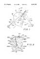
- FIG. 1shows one embodiment of the present invention which involves two video cameras and a space pointer with two light sources on it.
- FIG. 2shows an embodiment of the present invention with the space pointer pointing into a cranial operative site and where more than two video cameras are looking at the space pointer for redundancy.
- FIG. 3shows an embodiment of the present invention in which light sources at a distance from the pointer are used to reflect off reflectors on the pointer and the reflected light is detected by video cameras to ascertain the orientation of the space pointer.
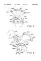
- FIG. 4shows an embodiment of the present invention in which two cameras are used and they visualize the anatomical field together with a space pointer, index marks on the patient's anatomy and a microscope so as to relate the position and aim of the microscope to the anatomy and the space pointer.
- FIG. 5shows a generalized, signal camera embodiment of the invention where the camera is coupled to a computer graphic means and the view of the camera looking at the patient anatomy is related to image data from image scan means so as to register the camera view and the image data to quantify the camera view field.
- FIG. 6shows a schematic representation of how camera field data would be registered in position and orientation to analagous image scan data on the same computer graphic display.
- FIG. 7shows a schematic view of two cameras looking at the anatomical subject with corresponding computer graphic views both of the camera, readout and field-of-view and of the computer graphic representation of the same view.
- FIG. 1shows a schematic view of one embodiment of the invention.
- the settingis neurosurgery and the patient 6 is being operated on through a skull hole 7.
- Probe 1is being put up to the patient's head and it is desired to know the relationship of that probe to the anatomy of the patient's as visualized from some imaging means such as CT or MR scanners or angiographic X-rays views. This image data representation of the patient's head would previously have been accumulated in a computer.
- the cameras 4 and 5may, for example be CCD Type compact TV Scanners with high resolution that can be easily digitized and video displayed or displayed on computer graphic screens. They are looking at the field including the patient's head 6 and the probe 1.
- index spots 8A, 8B and 8Cwhich may be placed on the patient's head.
- An alternative to these index spotsmight be a head ring which is fixed firmly to the patient's skull as is commonly done in surgery and that heading may have index points or lines on it which can be seen in the two views from the cameras 4 and 5.
- the appropriate transformationscan be made if the coordinates of the the physical points 8A, 8B, and 8C are known beforehand to the entire data set of anatomy in the computer. More than three points may also be used for redundancy or better field of view.
- the orientation of the light sources 2 and 3 relative to the anatomyis registered by the two cameras 4 and 5 and thus physical orientation of probe 1 relative to the head 6 is known. Since light sources 2 and 3 may be in a predetermined orientation relative to the tip of the probe 9, the actual physical location of the tip 9 relative to the anatomy may also be computed by the two views of the cameras 4 and 5. The orientation of the probe 1 may also be known from these two views. Thus, it is possible to display by the data accumulated by the cameras the orientation and absolute position of the probe relative to the anatomy, and this display can be made on computer graphics real time as the probe is moved around in a field near the anatomy.
- the probe within the entry hole 7is known, and thus the tip 9 can be graphically visualized on a computer display relative to anatomy inside the patient's head. This is most useful when exploring the interior of a surgical hole when the surgeon wishes to know the advancement of his probe or surgical instruments within that hole. Such an instrument may also be useful in planning the position of a surgical incision. By pointing the probe at the patient's skin and being able to visualize the position on the skin relative to relevant anatomy inside the head, the surgeon can make a judicious choice of entry point.
- the light sources 2 and 3may be LED light sources of very small dimension and they can be powered by an internal battery in the probe 1.
- the probemay thus be mechanically decoupled from other apparatus and only optically coupled through the cameras 4 and 5.
- This optical couplingcan be done in other ways. For example, there may be external light sources positioned nearby which can be reflected by tiny reflectors 2 and 3 on the probe. The reflected light can then be detected by cameras 4 and 5 giving the same optical registration of the probe position as though the light sources were sources of light on the probe itself.
- Cameras 4 and 5may have principle optical axes, 25 and 26 respectively shown in FIG. 1.
- the camerascan be aligned to be pointing in a plane and directed towards a common isocenter 29.
- all rays in the fieldsuch as rays 21 and 22 as seen from camera 4 to points 2 and 3 or rays 23 and 24 which also connect points 2 and 3 on the probe to the camera position 5 can be calibrated in the field of the cameras so that their exact angles relative to the principle rays indicated by 25 and 26 can be quantitatively determined.
- the position and orientation of the probe 1can be calculated relative to the point 29 which has been recalibrated.
- the exact referencing of the coordinate system represented by axes 25 and 26 with their crossover point 29 and orthogonal axis 27can be determined by further fiducial points on the anatomy itself. Natural anatomical fiducial points can be used such as the tip of the nose, the ears or other bony landmarks. However, specific index points such as 8A, 8B, and 8C can be placed on the patient's scalp, for example, and these used as a reference transformation set to relate the data seen by the cameras to anatomical data determined from the imaging.
- the exact coordinates of the points 8A, 8B, and 8Cmay have been determined in space from the scan data previously.
- the exact positions of these fiducial points onto the graphic display of the anatomical data from the imagescan be made.
- the exact positioning of the probe with its fiducial points 2 and 3can be thus set quantitatively into the field in a similar way. This corresponds to a series of 3-dimensional coordinate transformations and is a straight-forward mathematical matter.
- FIG. 2illustrates another embodiment to the present invention in which more than 2 cameras are involved.
- Cameras 204 and 205, as well as camera 210,are present and may prealigned or not prealigned prior to surgery. They are anchored on a support structure 230 which holds them rigidly in place and that support, in turn, is clamped by means of clamping means 231 to some stable object relative to the patient's head 206 such as the operating room table or the floor itself.
- Headholder 232may be a standard headholder as used in most operations with pin fixation points to the skull illustrated by 233, it too can be anchored to the operating table or to the floor by post 234 and, thus, the optical system above it and the head holder are stabilized relative to each other by means of their attachment to either themselves or to the operating table.
- the index points 202 and 203represent the fiducial points for the cameras 204, 205 and 210 and by digitizing the field of these cameras, one can determine the position and orientation of the probe 201.
- the index points 208A, B, and Cwhich represent independent fiducial points on the patient's head which can be also observed by the camera and the camera can, therefore, check the stability as well as their coordinate reference frame continuously by monitoring these fiducial points on the anatomy itself.
- There is a typical range of motion of the probe 201which is practical in such operations and this is illustrated as an example by the dashed cone 240. It must be that the camera can visualize the probe 201 and the fiducial points 202 and 203 everywhere within this working cone.
- the positions of the cameras 204, 205 and 210can be prearranged and precalibrated on the bar 230. This may be so that they are pointing isocentrically to the same point in that their visualization fields are precalibrated and preoriented so that everything within the field has a known calibration. This could also be easily checked by taking the platform 230 off at any given time and putting it on a phantom base or some other jig structure which enables instant calibration of the system. It is also true that the head holder 232 may have fiducial lights on it or fiducial points so that it may be referenced relative to the cameras and the entire system becomes an integral digitized calibrated system.
- FIG. 3shows another embodiment of the present invention in which external light sources are present as well as the cameras for receiving optical signals.
- Cameras 304 and 305are arranged and fixed to bar 330 for positioning.
- Light sources 342 and 341are also arranged and attached to the bar 330 so that they aim towards the probe 301 which has reflectors on it, 302 and 303 which reflect the light from the light sources 341 and 342.
- the camerasdetect the reflected light which is illustrated by the dashed light beams shown in FIG. 3. In this way the probe does not have to have any energy source or active light sources, but can be merely a reflector of light.
- the probeitself could be one, long reflective linear arrangement or could have other arrangements of the fiducial points instead of the the linear arrangement 302, which is coaxial with the probe. Any kind of pattern recognition of this type could be detected by the cameras and the corresponding digitization of the probe position and orientation could be made.
- headring 350which is affixed to the patient's head by a series of head posts 356 anchored securely to the skull.
- fiducial elements 351, 352 and 353which serve as index points and reference points that can also be detected optically by the cameras 304 and 305.
- the ring 350represents a platform and corresponding coordinate system basis, the position of the coordinate system being referenced by the fiducial points 351, 352 and 353 and monitored in terms of its relative position to the bar 330 and its associated cameras.
- the entire operative settingcould be monitored for any differences in position and position differences can be corrected for if they are determined by the computer graphics associated with the cameras 304 and 305.
- the need for discreet index points such as 302 and 303 on the space pointeris not absolutely necessary. Pattern recognition algorithms in a computer from data from cameras 304 and 305 may simply recognize the shape of the space pointer 301. Thus, the quantitation of its position in the field need not be done by discreet index points on the instrument.
- FIGS. 1, 2 and 3The major advantage of the probe illustrated in FIGS. 1, 2 and 3 are that they are mechanically decoupled from the observing cameras and thus there are no encumbrances of mechanical linkages such as a robotic arm as has been proposed in the past. It is also true that these probes can be made relatively simply and disposable so that the surgeon can throw the probe away after the procedure without incurring great expense.
- FIG. 4show another embodiment to the present invention with optical digitizing viewing means which involves not only a probe 401, but also an operating microscope 460.
- the objective hereis to determine quantitatively the relationship between the patient's head 406 and its anatomy within it, the space probe 401 and the operating microscope 460.
- the principleis essentially the same.
- the patient's headis 406 stabilized by the headholder 432.
- the microscopehas index means 462 and 463 which may be LED point light sources.
- the probe 401has its index points 402 and 403.
- Cameras 404 and 405are affixed to base platform 430 and view the entire field, microscope plus probe plus patient's head.
- Optical index points 408A, 408B, and 408Cmay be attached to the patient's scalp or to the headholder to provide referencing to the anatomy of both the probe and the microscope.
- the relationship of the position of the microscope 460 and its orientation relative to the anatomycan be determined.
- one can display on the graphicsmeans the field of view in which the microscope is viewing relative to that anatomy.
- computer graphics representations of the anatomyhave been made, then computer graphics of the field view with a microscope can also be represented on the graphics display means and, thus, the relationship between what the surgeon 461 is seeing and the computer reconstructed field may be made. This is very important in planning as well as interactive surgical recessions.
- probe 401may be inserted into the field and the position 409 of its tip can be represented within the actual microscopic viewing field of the microscope 460.
- the entire surgical array of instrumentsmay be represented graphically so that interactive correction and management of the operation can be made by the computer systems.
- One can also put other instruments within the fieldsuch as scalpels, probes and other devices which the surgeon commonly uses, these being indexed by fiducial marks or simply visualized directly by the cameras and representations of them put onto the graphics display means.
- FIGS. 1 through 4There are many variations of the embodiments shown in FIGS. 1 through 4.
- Such a multi-camera displaycould be precalibrated or not precalibrated.
- the camerascould be monitored and stabilized by fixed fiducial points somewhere in the field so that the entire registration and synchronization of all cameras would be possible.
- the mounting on which the cameras are heldcould be movable and changed interoperatively to be optimize the position of the cameras while maintaining registration with the subject field.
- the orientation of the cameras relative to the anatomy, microscope or probecould also be done without the need for fiducial lights such as two and three in FIG.
- the present inventionalso includes use of one optical camera.
- the examples aboveillustrate use of two or more cameras, there is utility in even using just one camera to view the surgical field. It can give you a two-dimensional representation in a projected view of the field. One can use this representation and the graphic representation from the image data to register the two views and, thus, align the graphic display in a "camera view".
- pointers in the field of the cameracan be registered directly on to the graphic display view. For example, a pointer moving on the surface of the skin would be registered relative to the graphic view so that you would know where that point is moving relative to this quantitative data that represents the skin and other anatomical structures below the skin. This would have more limited usefulness, but it could also be important.
- the application of mounting a single video camera to view a surgical field and representing that visual field on a graphic field so as to bring the two fields into alignment by manipulation of the graphic field in the computerhas utility in the surgical setting.
- FIG. 5illustrates more specifically the use of one optical viewing camera and registration of its field by computer graphics to image data.
- camera 505which has been anchored via arm 550 near the surgical field, views the patient's head 506 and objects nearby.
- the camerais connected via cable 551 to the computer graphics screen 552.
- the computer graphics screenis cooperatively connected to computer calculation means and storage means and it has represented on its screen image data from the image scanning source 554.
- This scanning sourcemay be a CT or MRI scanner or it may be a magnetic tape with corresponding data on it.
- the camera 505is viewing the head and representation of the head shows on the screen together with image data indicated by the contours 553.
- probe 501which is seen as 555 on the screen.
- index marks 508A, 508B, and 508Cwhich may aid in orienting what is seen by camera 505 to the graphics image data seen on screen 552.
- the headholder 532 and associated pins 533hold firmly the head 506 relative to the camera 505.
- the corresponding index points 558A, 558B, and 558Care shown on the screen as well as the actual image of the anatomy and the space probe represented by image 553.
- FIG. 6shows how one might register camera anatomical data to image machine-acquired anatomical data as described in the paragraph related to FIG. 5.
- the outline 606represents the actual contour of the patient's head as seen by the camera 505 in FIG. 5.
- the point 608A and 608B and 608Care shown as dots and these two are seen by the camera.
- anatomical landmarkssuch as 672, the tip of the ear, and 670, the tip of the nose, may be seen by the camera 505 in FIG. 5.
- the dashed contour in FIG. 6shows a similar contour reconstructed in a perspective view from, for example, CT slice image data.
- Such image datacan be stacked, can be surface rendered, and can be viewed and oriented from any different direction by computer graphics manipulation.
- FIG. 7illustrates another embodiment of how more than one camera can be used for computer graphic registration and corresponding quantification of an optical view.
- the fields of vieware shown with the dashed lines.
- Index points 702 and 703 on the probemay or may not be present and are analogous to those discussed in FIG. 1.
- Each of the cameraswill have views as illustrated in the lower portion of FIG. 7 and are displayed on the computer graphic display means 760 and 770.
- 760represents, for example, the view of camera 704 and one sees the solid line 766 which is the optical outline as seen by camera 704 of the patient's head. Similarly, the probe 761 is seen through the burr hole 767.
- computer graphic translation, rotation and scalingone can adjust the computer graphic view so that it matches the anatomical view, i.e. the computer graphic perimeter 766A indicated as dash line exactly matches 766. In this way, one knows that one has reproduced graphically with the dashed curve the projected view as seen by 704.
- camera 705will have its view as seen in graphic display 770 of the outline of the head 776 being matched to the graphic outline of the head 776A.
- index marks, grids or lines on the patient's scalpmight help in this registration of the two camera views.
- uniquely identifiable points in both viewscan give information on the exact 3-dimensional coordinates of those identifiable points relative to the anatomy as seen from the image data.
- the points 763 and 773are identical and correspond to the physical point 702 on the probe.
- this pointrepresents a projected line as seen from the respective camera.
- the two lines from the two camerasintersect at a unique point and this can easily be determined as a unique 3-dimensional point referenced to the data from the image scanner as stored in the computer.
- the two points 702 and 703can be determined quantitatively in space relative to the anatomical data, and thus, the quantitative position of the probe and any point on the probe can be determined relative to the image data.
- the end of the probe represented by point 709 which is in the depth of the brain and indicated on the graphics display as 769 and 779 respectivelycan be determined, i.e the 3-dimensional coordinates of that point relative to the 3-dimensional image anatomy can be determined.
- Mere registration of existing anatomical structures relative to camera view and the image datawould be sufficient for a full 3-dimensional representation of any instrument such as the probe in FIG. 7 relative to the anatomy. Using special angles such as 90° or stereoscopic views of the cameras could be convenient for such 3-dimensional registration without prior calibration.
- Kelly's methoddiffers in a fundamental way from what is being claimed in this invention.
- the present inventionincludes in its scope the use of one or more cameras in the the context illustrated by FIGS. 1 through 7. It includes the use of a camera together with a computer and computer graphic means to register and relate optical viewing to image data from other scanning and imaging devices. It also relates to the use of such optical and image data correspondences to register and quantify the position of surgical tools such as the space probe or the microscope illustrated in the above examples. It is related to making the associated mathematical transformation from a coordinate system or perspective view seen by one or more cameras to a stereotactic coordinate system related to image data or a corresponding reconstructive perspective view of image data and associated coordinate information from such image data.
- the inventionsubsumes the field of generalized camera viewing or projected image acquisition relative to CT, MRI or angiography acquisition from other imaging means and the registration thereafter to make correspondence between these two image acquisition modalities.
- FIGS. 1 through 4illustrate this by use of a probe with two fiducial points on it that can be seen and digitized by the two camera views.
- This inventionrelates to the use of a video camera to quantitatively relate to graphic display data taken from other imaging means. The correspondence of the data are illustrated by the embodiments above and the discussion above, but those skilled in the art could think of other implementations of the same invention concept.
- the use of two fiducial points on the probecan be extended to other types of optical fiducial means such as lines, other arrays of points, other geometric patterns and figures that can be recognized easily by computer graphics, artificial intelligence, etc.
- the two points illustrated in the figuresbe replaced by a line of light or a line of light and one or more discrete points to encode the direction of the object.
- the object itselfcould be recognized by the computer graphics as a line merely by having it of a reflective material or a particular color.
- the space pointerfor instance, could be white or green and thus show up differently on the TV cameras and in the video display so as to recognize it as the pointer.
Landscapes
- Health & Medical Sciences (AREA)
- Surgery (AREA)
- Life Sciences & Earth Sciences (AREA)
- Heart & Thoracic Surgery (AREA)
- Pathology (AREA)
- Oral & Maxillofacial Surgery (AREA)
- Engineering & Computer Science (AREA)
- Biomedical Technology (AREA)
- Nuclear Medicine, Radiotherapy & Molecular Imaging (AREA)
- Medical Informatics (AREA)
- Molecular Biology (AREA)
- Animal Behavior & Ethology (AREA)
- General Health & Medical Sciences (AREA)
- Public Health (AREA)
- Veterinary Medicine (AREA)
- Magnetic Resonance Imaging Apparatus (AREA)
Abstract
Description
Claims (7)
Priority Applications (1)
| Application Number | Priority Date | Filing Date | Title |
|---|---|---|---|
| US08/590,044US6167295A (en) | 1991-01-28 | 1996-01-03 | Optical and computer graphic stereotactic localizer |
Applications Claiming Priority (3)
| Application Number | Priority Date | Filing Date | Title |
|---|---|---|---|
| US64730591A | 1991-01-28 | 1991-01-28 | |
| US20513894A | 1994-03-02 | 1994-03-02 | |
| US08/590,044US6167295A (en) | 1991-01-28 | 1996-01-03 | Optical and computer graphic stereotactic localizer |
Related Parent Applications (1)
| Application Number | Title | Priority Date | Filing Date |
|---|---|---|---|
| US20513894AContinuation | 1991-01-28 | 1994-03-02 |
Publications (1)
| Publication Number | Publication Date |
|---|---|
| US6167295Atrue US6167295A (en) | 2000-12-26 |
Family
ID=26900138
Family Applications (1)
| Application Number | Title | Priority Date | Filing Date |
|---|---|---|---|
| US08/590,044Expired - Fee RelatedUS6167295A (en) | 1991-01-28 | 1996-01-03 | Optical and computer graphic stereotactic localizer |
Country Status (1)
| Country | Link |
|---|---|
| US (1) | US6167295A (en) |
Cited By (76)
| Publication number | Priority date | Publication date | Assignee | Title |
|---|---|---|---|---|
| US6259943B1 (en)* | 1995-02-16 | 2001-07-10 | Sherwood Services Ag | Frameless to frame-based registration system |
| US6491702B2 (en)* | 1992-04-21 | 2002-12-10 | Sofamor Danek Holdings, Inc. | Apparatus and method for photogrammetric surgical localization |
| US6585651B2 (en) | 1999-04-20 | 2003-07-01 | Synthes Ag Chur | Method and device for percutaneous determination of points associated with the surface of an organ |
| WO2003028577A3 (en)* | 2001-10-03 | 2003-10-02 | Univ Texas | Method and apparatus for fabricating orthognathic surgical splints |
| US20030229279A1 (en)* | 2000-11-03 | 2003-12-11 | Christoph Amstutz | Determination of deformations of surgical tools |
| US20040002641A1 (en)* | 2002-06-24 | 2004-01-01 | Bo Sjogren | Patient representation in medical machines |
| DE10249025A1 (en)* | 2002-06-13 | 2004-01-08 | Möller-Wedel GmbH | Surgical neural navigation method in which an optoelectronic image detector, operation microscope and computer are used to continuously determine the 3-dimensional position of a medical instrument, especially its tip |
| US6694168B2 (en) | 1998-06-22 | 2004-02-17 | Synthes (U.S.A.) | Fiducial matching using fiducial implants |
| US6725082B2 (en) | 1999-03-17 | 2004-04-20 | Synthes U.S.A. | System and method for ligament graft placement |
| US20040207661A1 (en)* | 2002-12-27 | 2004-10-21 | Kabushiki Kaisha Toshiba | Medical imaging apparatus which displays predetermined information in differentiable manner from others |
| EP1517647A1 (en)* | 2002-06-13 | 2005-03-30 | Möller-Wedel GmbH | Method and instrument for surgical navigation |
| US20050104849A1 (en)* | 2001-12-21 | 2005-05-19 | British Telecommunications Public Limited Company | Device and method for calculating a location on a display |
| US20050131426A1 (en)* | 2003-12-10 | 2005-06-16 | Moctezuma De La Barrera Jose L. | Adapter for surgical navigation trackers |
| WO2005067807A1 (en) | 2004-01-09 | 2005-07-28 | Ecole Polytechnique Federale De Lausanne (Epfl) | Surgical navigation system |
| WO2005065272A3 (en)* | 2003-12-30 | 2005-10-06 | Trustees Stevens Inst Tech | Three-dimensional imaging system using optical pulses, non-linear optical mixers and holographic calibration |
| US20050288575A1 (en)* | 2003-12-10 | 2005-12-29 | De La Barrera Jose Luis M | Surgical navigation tracker, system and method |
| WO2005095931A3 (en)* | 2004-02-11 | 2006-05-18 | Reveal Imaging Technologies In | Contraband detection systems and methods |
| US7166114B2 (en) | 2002-09-18 | 2007-01-23 | Stryker Leibinger Gmbh & Co Kg | Method and system for calibrating a surgical tool and adapter thereof |
| US7237556B2 (en) | 2002-02-11 | 2007-07-03 | Smith & Nephew, Inc. | Image-guided fracture reduction |
| US7277594B2 (en) | 1999-05-03 | 2007-10-02 | Ao Technology Ag | System and method for preparing an image corrected for the presence of a gravity induced distortion |
| US20080031409A1 (en)* | 2006-08-07 | 2008-02-07 | David Phillipe Sarment | Ct scanner including a camera to obtain external images of a patient |
| US20080112699A1 (en)* | 2006-11-13 | 2008-05-15 | Honeywell International Inc. | Method and system for automatically estimating the spatial positions of cameras in a camera network |
| US20080122958A1 (en)* | 2006-11-29 | 2008-05-29 | Honeywell International Inc. | Method and system for automatically determining the camera field of view in a camera network |
| US7477926B2 (en) | 2004-03-31 | 2009-01-13 | Smith & Nephew, Inc. | Methods and apparatuses for providing a reference array input device |
| CN100464720C (en)* | 2005-12-22 | 2009-03-04 | 天津市华志计算机应用技术有限公司 | Brain surgery robot system and implementation method based on optical tracking closed-loop control |
| US7547307B2 (en) | 2001-02-27 | 2009-06-16 | Smith & Nephew, Inc. | Computer assisted knee arthroplasty instrumentation, systems, and processes |
| US20090245569A1 (en)* | 2008-03-31 | 2009-10-01 | Egger Ron D | Optical Imaging Based Computer Pointing |
| US20090259960A1 (en)* | 2008-04-09 | 2009-10-15 | Wolfgang Steinle | Image-based controlling method for medical apparatuses |
| US7623250B2 (en) | 2005-02-04 | 2009-11-24 | Stryker Leibinger Gmbh & Co. Kg. | Enhanced shape characterization device and method |
| US7643867B2 (en) | 2003-02-25 | 2010-01-05 | Medtronic, Inc. | Fiducial marker devices, tools, and methods |
| US20100168763A1 (en)* | 2008-12-31 | 2010-07-01 | Intuitive Surgical, Inc. | Configuration marker design and detection for instrument tracking |
| US20100168562A1 (en)* | 2008-12-31 | 2010-07-01 | Intuitive Surgical, Inc. | Fiducial marker design and detection for locating surgical instrument in images |
| US7764985B2 (en) | 2003-10-20 | 2010-07-27 | Smith & Nephew, Inc. | Surgical navigation system component fault interfaces and related processes |
| US7787934B2 (en) | 2002-07-29 | 2010-08-31 | Medtronic, Inc. | Fiducial marker devices, tools, and methods |
| US7794467B2 (en) | 2003-11-14 | 2010-09-14 | Smith & Nephew, Inc. | Adjustable surgical cutting systems |
| US7862570B2 (en) | 2003-10-03 | 2011-01-04 | Smith & Nephew, Inc. | Surgical positioners |
| US8109942B2 (en) | 2004-04-21 | 2012-02-07 | Smith & Nephew, Inc. | Computer-aided methods, systems, and apparatuses for shoulder arthroplasty |
| US8177788B2 (en) | 2005-02-22 | 2012-05-15 | Smith & Nephew, Inc. | In-line milling system |
| CN103033525A (en)* | 2011-09-30 | 2013-04-10 | 清华大学 | CT (computed tomography) system and CT image reconstruction method |
| US8425522B2 (en) | 2000-01-14 | 2013-04-23 | Bonutti Skeletal Innovations Llc | Joint replacement method |
| US20130102893A1 (en)* | 2010-06-30 | 2013-04-25 | Fritz Vollmer | Medical image registration using a rigid inner body surface |
| US8623030B2 (en) | 2001-08-28 | 2014-01-07 | Bonutti Skeletal Innovations Llc | Robotic arthroplasty system including navigation |
| US20140133730A1 (en)* | 2012-11-09 | 2014-05-15 | National Central University | Time synchronization calibration method and system for image taking and coordinate reading and delay time calculation method thereof |
| US8728092B2 (en) | 2008-08-14 | 2014-05-20 | Monteris Medical Corporation | Stereotactic drive system |
| US8747418B2 (en) | 2008-08-15 | 2014-06-10 | Monteris Medical Corporation | Trajectory guide |
| US8979871B2 (en) | 2009-08-13 | 2015-03-17 | Monteris Medical Corporation | Image-guided therapy of a tissue |
| US9008757B2 (en) | 2012-09-26 | 2015-04-14 | Stryker Corporation | Navigation system including optical and non-optical sensors |
| US9216015B2 (en) | 2004-10-28 | 2015-12-22 | Vycor Medical, Inc. | Apparatus and methods for performing brain surgery |
| WO2016026437A1 (en)* | 2014-08-19 | 2016-02-25 | Chen Chieh Hsiao | Method and system of determining probe position in surgical site |
| US9307969B2 (en) | 2005-06-17 | 2016-04-12 | Vycor Medical, Inc. | Tissue retractor apparatus and methods |
| US9333038B2 (en) | 2000-06-15 | 2016-05-10 | Monteris Medical Corporation | Hyperthermia treatment and probe therefore |
| US20160187481A1 (en)* | 2014-10-30 | 2016-06-30 | Seno Medical Instruments, Inc. | Opto-acoustic imaging system with detection of relative orientation of light source and acoustic receiver using acoustic waves |
| CN105852979A (en)* | 2016-03-23 | 2016-08-17 | 北京柏惠维康科技有限公司 | Medical image space localization device and method |
| US9433383B2 (en) | 2014-03-18 | 2016-09-06 | Monteris Medical Corporation | Image-guided therapy of a tissue |
| US20160267659A1 (en)* | 2013-10-25 | 2016-09-15 | Brainlab Ag | Method and device for co-registering a medical 3d image and a spatial reference |
| US9498231B2 (en) | 2011-06-27 | 2016-11-22 | Board Of Regents Of The University Of Nebraska | On-board tool tracking system and methods of computer assisted surgery |
| US9504484B2 (en) | 2014-03-18 | 2016-11-29 | Monteris Medical Corporation | Image-guided therapy of a tissue |
| US20170014203A1 (en)* | 2014-02-24 | 2017-01-19 | Universite De Strasbourg (Etablissement Public National A Caractere Scientifiqu, Culturel Et Prof | Automatic multimodal real-time tracking of a moving marker for image plane alignment inside a mri scanner |
| US9737287B2 (en) | 2014-05-13 | 2017-08-22 | Vycor Medical, Inc. | Guidance system mounts for surgical introducers |
| US10105149B2 (en) | 2013-03-15 | 2018-10-23 | Board Of Regents Of The University Of Nebraska | On-board tool tracking system and methods of computer assisted surgery |
| US10183143B2 (en) | 2013-03-15 | 2019-01-22 | Bitol Designs, Llc | Occlusion resistant catheter and method of use |
| US10219811B2 (en) | 2011-06-27 | 2019-03-05 | Board Of Regents Of The University Of Nebraska | On-board tool tracking system and methods of computer assisted surgery |
| US10327830B2 (en) | 2015-04-01 | 2019-06-25 | Monteris Medical Corporation | Cryotherapy, thermal therapy, temperature modulation therapy, and probe apparatus therefor |
| US10376258B2 (en) | 2016-11-07 | 2019-08-13 | Vycor Medical, Inc. | Surgical introducer with guidance system receptacle |
| CN110461270A (en)* | 2017-02-14 | 2019-11-15 | 阿特雷塞斯有限责任公司 | High-speed optical tracking with compression and/or CMOS windowing |
| US10543016B2 (en) | 2016-11-07 | 2020-01-28 | Vycor Medical, Inc. | Surgical introducer with guidance system receptacle |
| US10675113B2 (en) | 2014-03-18 | 2020-06-09 | Monteris Medical Corporation | Automated therapy of a three-dimensional tissue region |
| US10716618B2 (en) | 2010-05-21 | 2020-07-21 | Stratus Medical, LLC | Systems and methods for tissue ablation |
| US10736688B2 (en) | 2009-11-05 | 2020-08-11 | Stratus Medical, LLC | Methods and systems for spinal radio frequency neurotomy |
| US11116574B2 (en) | 2006-06-16 | 2021-09-14 | Board Of Regents Of The University Of Nebraska | Method and apparatus for computer aided surgery |
| DE102020108345A1 (en) | 2020-03-26 | 2021-09-30 | Carl Zeiss Meditec Ag | Reading in codes using a surgical microscope camera |
| US11291852B2 (en) | 2018-02-06 | 2022-04-05 | The Board Of Trustees Of The Leland Stanford Junior University | Accurate patient-specific targeting of cranial therapy using a brain atlas |
| US11911117B2 (en) | 2011-06-27 | 2024-02-27 | Board Of Regents Of The University Of Nebraska | On-board tool tracking system and methods of computer assisted surgery |
| US12178469B2 (en) | 2016-11-07 | 2024-12-31 | Vycor Medical Inc. | Surgical introducer with guidance system receptacle |
| US12357397B2 (en)* | 2022-05-09 | 2025-07-15 | Proprio, Inc. | Methods and systems for calibrating instruments within an imaging system, such as a surgical imaging system |
| US12383350B2 (en) | 2021-09-08 | 2025-08-12 | Proprio, Inc. | Constellations for tracking instruments, such as surgical instruments, and associated systems and methods |
Citations (130)
| Publication number | Priority date | Publication date | Assignee | Title |
|---|---|---|---|---|
| FR1282623A (en) | 1960-12-13 | 1962-01-27 | Alexandre & Cie Sa | New device for stereotaxic brain surgery |
| US3777124A (en)* | 1970-11-27 | 1973-12-04 | Varian Associates | Computer assisted radiation therapy machine |
| US3821469A (en)* | 1972-05-15 | 1974-06-28 | Amperex Electronic Corp | Graphical data device |
| US3983474A (en)* | 1975-02-21 | 1976-09-28 | Polhemus Navigation Sciences, Inc. | Tracking and determining orientation of object using coordinate transformation means, system and process |
| US4058114A (en)* | 1974-09-11 | 1977-11-15 | Siemens Aktiengesellschaft | Ultrasonic arrangement for puncturing internal body organs, vessels and the like |
| US4068156A (en)* | 1977-03-01 | 1978-01-10 | Martin Marietta Corporation | Rate control system for manipulator arms |
| US4182312A (en)* | 1977-05-20 | 1980-01-08 | Mushabac David R | Dental probe |
| EP0018166A1 (en) | 1979-04-13 | 1980-10-29 | Pfizer Inc. | Apparatus for use in stereotactic surgery |
| US4262306A (en)* | 1977-04-27 | 1981-04-14 | Karlheinz Renner | Method and apparatus for monitoring of positions of patients and/or radiation units |
| US4319136A (en)* | 1979-11-09 | 1982-03-09 | Jinkins J Randolph | Computerized tomography radiograph data transfer cap |
| GB2094590A (en) | 1981-02-12 | 1982-09-15 | Univ New York | Apparatus for stereotactic surgery |
| US4358856A (en)* | 1980-10-31 | 1982-11-09 | General Electric Company | Multiaxial x-ray apparatus |
| US4386602A (en)* | 1977-05-17 | 1983-06-07 | Sheldon Charles H | Intracranial surgical operative apparatus |
| FR2417970B1 (en) | 1978-02-22 | 1983-12-16 | Howmedica | |
| US4463758A (en)* | 1981-09-18 | 1984-08-07 | Arun A. Patil | Computed tomography stereotactic frame |
| US4465069A (en)* | 1981-06-04 | 1984-08-14 | Barbier Jean Y | Cranial insertion of surgical needle utilizing computer-assisted tomography |
| US4473074A (en)* | 1981-09-28 | 1984-09-25 | Xanar, Inc. | Microsurgical laser device |
| EP0062941B1 (en) | 1981-04-08 | 1984-09-26 | Koninklijke Philips Electronics N.V. | Contour recording device |
| US4506676A (en)* | 1982-09-10 | 1985-03-26 | Duska Alois A | Radiographic localization technique |
| EP0146699A1 (en) | 1983-12-22 | 1985-07-03 | GebràDer Sulzer Aktiengesellschaft | Implanted marker |
| US4583538A (en)* | 1984-05-04 | 1986-04-22 | Onik Gary M | Method and apparatus for stereotaxic placement of probes in the body utilizing CT scanner localization |
| US4592352A (en)* | 1984-11-30 | 1986-06-03 | Patil Arun A | Computer-assisted tomography stereotactic system |
| US4598368A (en)* | 1982-12-27 | 1986-07-01 | Tokyo Shibaura Denki Kabushiki Kaisha | Superposed image display device |
| US4602622A (en)* | 1979-12-05 | 1986-07-29 | Siemens Aktiengesellschaft | Medical examination installation |
| US4608977A (en)* | 1979-08-29 | 1986-09-02 | Brown Russell A | System using computed tomography as for selective body treatment |
| DE3508730A1 (en) | 1985-03-12 | 1986-09-18 | Siemens AG, 1000 Berlin und 8000 München | Measuring device for medical purposes |
| US4617925A (en)* | 1984-10-01 | 1986-10-21 | Laitinen Lauri V | Adapter for definition of the position of brain structures |
| US4618978A (en)* | 1983-10-21 | 1986-10-21 | Cosman Eric R | Means for localizing target coordinates in a body relative to a guidance system reference frame in any arbitrary plane as viewed by a tomographic image through the body |
| US4638798A (en)* | 1980-09-10 | 1987-01-27 | Shelden C Hunter | Stereotactic method and apparatus for locating and treating or removing lesions |
| US4651732A (en)* | 1983-03-17 | 1987-03-24 | Frederick Philip R | Three-dimensional light guidance system for invasive procedures |
| US4653509A (en)* | 1985-07-03 | 1987-03-31 | The United States Of America As Represented By The Secretary Of The Air Force | Guided trephine samples for skeletal bone studies |
| US4659971A (en)* | 1984-08-16 | 1987-04-21 | Seiko Instruments & Electronics Ltd. | Robot controlling system |
| US4660970A (en)* | 1983-11-25 | 1987-04-28 | Carl-Zeiss-Stiftung | Method and apparatus for the contact-less measuring of objects |
| US4674057A (en)* | 1984-02-14 | 1987-06-16 | Lockheed Corporation | Ultrasonic ranging control system for industrial robots |
| US4686997A (en)* | 1985-07-03 | 1987-08-18 | The United States Of America As Represented By The Secretary Of The Air Force | Skeletal bone remodeling studies using guided trephine sample |
| US4698777A (en)* | 1983-05-26 | 1987-10-06 | Fanuc Ltd. | Industrial robot circular arc control method for controlling the angle of a tool |
| US4701049A (en)* | 1983-06-22 | 1987-10-20 | B.V. Optische Industrie "De Oude Delft" | Measuring system employing a measuring method based on the triangulation principle for the non-contact measurement of a distance from the surface of a contoured object to a reference level. _ |
| US4705401A (en)* | 1985-08-12 | 1987-11-10 | Cyberware Laboratory Inc. | Rapid three-dimensional surface digitizer |
| US4705395A (en)* | 1984-10-03 | 1987-11-10 | Diffracto Ltd. | Triangulation data integrity |
| US4706665A (en)* | 1984-12-17 | 1987-11-17 | Gouda Kasim I | Frame for stereotactic surgery |
| US4709756A (en)* | 1984-11-13 | 1987-12-01 | Westinghouse Electric Corp. | Steam generator tube support |
| US4722056A (en)* | 1986-02-18 | 1988-01-26 | Trustees Of Dartmouth College | Reference display systems for superimposing a tomagraphic image onto the focal plane of an operating microscope |
| US4722336A (en)* | 1985-01-25 | 1988-02-02 | Michael Kim | Placement guide |
| US4723544A (en)* | 1986-07-09 | 1988-02-09 | Moore Robert R | Hemispherical vectoring needle guide for discolysis |
| US4733969A (en)* | 1986-09-08 | 1988-03-29 | Cyberoptics Corporation | Laser probe for determining distance |
| US4733661A (en)* | 1987-04-27 | 1988-03-29 | Palestrant Aubrey M | Guidance device for C.T. guided drainage and biopsy procedures |
| US4737032A (en)* | 1985-08-26 | 1988-04-12 | Cyberware Laboratory, Inc. | Surface mensuration sensor |
| US4743770A (en)* | 1986-09-22 | 1988-05-10 | Mitutoyo Mfg. Co., Ltd. | Profile-measuring light probe using a change in reflection factor in the proximity of a critical angle of light |
| US4742815A (en)* | 1986-01-02 | 1988-05-10 | Ninan Champil A | Computer monitoring of endoscope |
| US4743771A (en)* | 1985-06-17 | 1988-05-10 | View Engineering, Inc. | Z-axis height measurement system |
| US4745290A (en)* | 1987-03-19 | 1988-05-17 | David Frankel | Method and apparatus for use in making custom shoes |
| US4750487A (en)* | 1986-11-24 | 1988-06-14 | Zanetti Paul H | Stereotactic frame |
| US4753528A (en)* | 1983-12-13 | 1988-06-28 | Quantime, Inc. | Laser archery distance device |
| US4761072A (en)* | 1986-09-30 | 1988-08-02 | Diffracto Ltd. | Electro-optical sensors for manual control |
| US4760851A (en)* | 1986-03-31 | 1988-08-02 | Faro Medical Technologies Inc. | 3-dimensional digitizer for skeletal analysis |
| US4762016A (en)* | 1987-03-27 | 1988-08-09 | The Regents Of The University Of California | Robotic manipulator having three degrees of freedom |
| US4764016A (en)* | 1985-06-14 | 1988-08-16 | Anders Bengtsson | Instrument for measuring the topography of a surface |
| US4776749A (en)* | 1986-03-25 | 1988-10-11 | Northrop Corporation | Robotic device |
| US4779212A (en)* | 1985-09-27 | 1988-10-18 | Levy Nessim I | Distance measuring device |
| US4782239A (en)* | 1985-04-05 | 1988-11-01 | Nippon Kogaku K. K. | Optical position measuring apparatus |
| US4791934A (en)* | 1986-08-07 | 1988-12-20 | Picker International, Inc. | Computer tomography assisted stereotactic surgery system and method |
| US4794262A (en)* | 1985-12-03 | 1988-12-27 | Yukio Sato | Method and apparatus for measuring profile of three-dimensional object |
| US4797736A (en)* | 1987-09-02 | 1989-01-10 | Luxtec Corporation | Head mounted illumination and camera assembly |
| US4805615A (en)* | 1985-07-02 | 1989-02-21 | Carol Mark P | Method and apparatus for performing stereotactic surgery |
| US4809694A (en)* | 1987-05-19 | 1989-03-07 | Ferrara Vincent L | Biopsy guide |
| US4821200A (en)* | 1986-04-14 | 1989-04-11 | Jonkopings Lans Landsting | Method and apparatus for manufacturing a modified, three-dimensional reproduction of a soft, deformable object |
| US4821206A (en)* | 1984-11-27 | 1989-04-11 | Photo Acoustic Technology, Inc. | Ultrasonic apparatus for positioning a robot hand |
| US4822163A (en)* | 1986-06-26 | 1989-04-18 | Robotic Vision Systems, Inc. | Tracking vision sensor |
| US4825091A (en)* | 1987-02-05 | 1989-04-25 | Carl-Zeiss-Stiftung | Optoelectronic distance sensor with visible pilot beam |
| US4826487A (en)* | 1987-05-04 | 1989-05-02 | Victory Engineering Company | Alignment button for stereotaxic plug and method of using the same |
| US4829373A (en)* | 1987-08-03 | 1989-05-09 | Vexcel Corporation | Stereo mensuration apparatus |
| US4835710A (en)* | 1987-07-17 | 1989-05-30 | Cincinnati Milacron Inc. | Method of moving and orienting a tool along a curved path |
| US4836778A (en)* | 1987-05-26 | 1989-06-06 | Vexcel Corporation | Mandibular motion monitoring system |
| US4838265A (en)* | 1985-05-24 | 1989-06-13 | Cosman Eric R | Localization device for probe placement under CT scanner imaging |
| US4841967A (en)* | 1984-01-30 | 1989-06-27 | Chang Ming Z | Positioning device for percutaneous needle insertion |
| US4845626A (en)* | 1987-04-03 | 1989-07-04 | Kabushiki Kaisha Toshiba | Stereoscopic image display apparatus |
| US4859181A (en)* | 1986-09-11 | 1989-08-22 | Stefan Neumeyer | Method and apparatus for measuring relative jaw movement |
| US4869247A (en)* | 1988-03-11 | 1989-09-26 | The University Of Virginia Alumni Patents Foundation | Video tumor fighting system |
| US4875478A (en)* | 1987-04-10 | 1989-10-24 | Chen Harry H | Portable compression grid & needle holder |
| US4884566A (en)* | 1988-04-15 | 1989-12-05 | The University Of Michigan | System and method for determining orientation of planes of imaging |
| US4896673A (en)* | 1988-07-15 | 1990-01-30 | Medstone International, Inc. | Method and apparatus for stone localization using ultrasound imaging |
| US4931056A (en)* | 1987-09-04 | 1990-06-05 | Neurodynamics, Inc. | Catheter guide apparatus for perpendicular insertion into a cranium orifice |
| US4933843A (en)* | 1986-11-06 | 1990-06-12 | Storz Instrument Company | Control system for ophthalmic surgical instruments |
| US4943296A (en)* | 1986-03-28 | 1990-07-24 | Life Technology Research Foundation | Robot for surgical operation |
| US4945914A (en)* | 1987-11-10 | 1990-08-07 | Allen George S | Method and apparatus for providing related images over time of a portion of the anatomy using at least four fiducial implants |
| US4961422A (en)* | 1983-01-21 | 1990-10-09 | Marchosky J Alexander | Method and apparatus for volumetric interstitial conductive hyperthermia |
| US4979222A (en)* | 1989-02-21 | 1990-12-18 | Joerg Weber | Method for producing a third image that clarifies the differences between two images which are allocated to one another |
| US4985019A (en)* | 1988-03-11 | 1991-01-15 | Michelson Gary K | X-ray marker |
| EP0326768A3 (en) | 1988-02-01 | 1991-01-23 | Faro Medical Technologies Inc. | Computer-aided surgery apparatus |
| US5017139A (en)* | 1990-07-05 | 1991-05-21 | Mushabac David R | Mechanical support for hand-held dental/medical instrument |
| US5027818A (en)* | 1987-12-03 | 1991-07-02 | University Of Florida | Dosimetric technique for stereotactic radiosurgery same |
| GB2213066B (en) | 1987-12-02 | 1991-07-17 | Inst Of Neurology | Head fixation apparatus |
| US5047036A (en)* | 1989-11-17 | 1991-09-10 | Koutrouvelis Panos G | Stereotactic device |
| US5052035A (en)* | 1989-11-02 | 1991-09-24 | Webb Research Ii Corporation | Image location marking devices for radiographs, method of making and methods of use |
| US5050608A (en)* | 1988-07-12 | 1991-09-24 | Medirand, Inc. | System for indicating a position to be operated in a patient's body |
| US5056523A (en)* | 1989-11-22 | 1991-10-15 | Board Of Regents, The University Of Texas System | Precision breast lesion localizer |
| US5070454A (en)* | 1988-03-24 | 1991-12-03 | Olganix Corporation | Reference marker orientation system for a radiographic film-based computerized tomography system |
| US5078140A (en)* | 1986-05-08 | 1992-01-07 | Kwoh Yik S | Imaging device - aided robotic stereotaxis system |
| US5080662A (en)* | 1989-11-27 | 1992-01-14 | Paul Kamaljit S | Spinal stereotaxic device and method |
| US5086401A (en)* | 1990-05-11 | 1992-02-04 | International Business Machines Corporation | Image-directed robotic system for precise robotic surgery including redundant consistency checking |
| US5099846A (en)* | 1988-12-23 | 1992-03-31 | Hardy Tyrone L | Method and apparatus for video presentation from a variety of scanner imaging sources |
| US5107839A (en)* | 1990-05-04 | 1992-04-28 | Pavel V. Houdek | Computer controlled stereotaxic radiotherapy system and method |
| US5116344A (en)* | 1987-04-27 | 1992-05-26 | Elekta Instrument Ab | Apparatus for marking an operating site |
| US5142559A (en) | 1990-05-11 | 1992-08-25 | The Research Foundation Of State University Of New York | Radiation detection system including radiation alignment means and isocentrically rotatable detectors |
| US5142930A (en) | 1987-11-10 | 1992-09-01 | Allen George S | Interactive image-guided surgical system |
| US5147372A (en) | 1988-07-13 | 1992-09-15 | Bernt Nymark | Biopsy arc means and the use of the same |
| US5154179A (en) | 1987-07-02 | 1992-10-13 | Medical Magnetics, Inc. | Device construction and method facilitating magnetic resonance imaging of foreign objects in a body |
| US5163430A (en) | 1990-04-27 | 1992-11-17 | Medco, Inc. | Method and apparatus for performing stereotactic surgery |
| US5165410A (en) | 1987-05-15 | 1992-11-24 | Medical & Scientific Enterprises, Inc. | Position indicating system for a multidiagnostic scanner |
| US5173946A (en) | 1991-05-31 | 1992-12-22 | Texas Instruments Incorporated | Corner-based image matching |
| US5178146A (en) | 1988-11-03 | 1993-01-12 | Giese William L | Grid and patient alignment system for use with MRI and other imaging modalities |
| US5186174A (en) | 1987-05-21 | 1993-02-16 | G. M. Piaff | Process and device for the reproducible optical representation of a surgical operation |
| US5193106A (en) | 1990-08-28 | 1993-03-09 | Desena Danforth | X-ray identification marker |
| US5198977A (en) | 1990-11-27 | 1993-03-30 | Jesse Salb | System and method for localization of functional activity in the human brain |
| US5197476A (en) | 1989-03-16 | 1993-03-30 | Christopher Nowacki | Locating target in human body |
| US5207223A (en) | 1990-10-19 | 1993-05-04 | Accuray, Inc. | Apparatus for and method of performing stereotaxic surgery |
| US5224049A (en) | 1990-04-10 | 1993-06-29 | Mushabac David R | Method, system and mold assembly for use in preparing a dental prosthesis |
| US5247555A (en) | 1988-10-28 | 1993-09-21 | Nucletron Manufacturing Corp. | Radiation image generating system and method |
| US5251127A (en) | 1988-02-01 | 1993-10-05 | Faro Medical Technologies Inc. | Computer-aided surgery apparatus |
| US5257998A (en) | 1989-09-20 | 1993-11-02 | Mitaka Kohki Co., Ltd. | Medical three-dimensional locating apparatus |
| US5269305A (en) | 1990-04-27 | 1993-12-14 | The Nomos Corporation | Method and apparatus for performing stereotactic surgery |
| US5280427A (en) | 1989-11-27 | 1994-01-18 | Bard International, Inc. | Puncture guide for computer tomography |
| US5285787A (en) | 1989-09-12 | 1994-02-15 | Kabushiki Kaisha Toshiba | Apparatus for calculating coordinate data of desired point in subject to be examined |
| US5295483A (en) | 1990-05-11 | 1994-03-22 | Christopher Nowacki | Locating target in human body |
| US5354314A (en) | 1988-12-23 | 1994-10-11 | Medical Instrumentation And Diagnostics Corporation | Three-dimensional beam localization apparatus and microscope for stereotactic diagnoses or surgery mounted on robotic type arm |
| US5383454A (en) | 1990-10-19 | 1995-01-24 | St. Louis University | System for indicating the position of a surgical probe within a head on an image of the head |
| US5622170A (en) | 1990-10-19 | 1997-04-22 | Image Guided Technologies, Inc. | Apparatus for determining the position and orientation of an invasive portion of a probe inside a three-dimensional body |
| US5662111A (en) | 1991-01-28 | 1997-09-02 | Cosman; Eric R. | Process of stereotactic optical navigation |
| US5792146A (en) | 1990-10-09 | 1998-08-11 | Cosman; Eric R. | Rectilinear linac phantom pointer system |
| US5836954A (en) | 1992-04-21 | 1998-11-17 | University Of Utah Research Foundation | Apparatus and method for photogrammetric surgical localization |
- 1996
- 1996-01-03USUS08/590,044patent/US6167295A/ennot_activeExpired - Fee Related
Patent Citations (146)
| Publication number | Priority date | Publication date | Assignee | Title |
|---|---|---|---|---|
| FR1282623A (en) | 1960-12-13 | 1962-01-27 | Alexandre & Cie Sa | New device for stereotaxic brain surgery |
| US3777124A (en)* | 1970-11-27 | 1973-12-04 | Varian Associates | Computer assisted radiation therapy machine |
| US3821469A (en)* | 1972-05-15 | 1974-06-28 | Amperex Electronic Corp | Graphical data device |
| US4058114A (en)* | 1974-09-11 | 1977-11-15 | Siemens Aktiengesellschaft | Ultrasonic arrangement for puncturing internal body organs, vessels and the like |
| US3983474A (en)* | 1975-02-21 | 1976-09-28 | Polhemus Navigation Sciences, Inc. | Tracking and determining orientation of object using coordinate transformation means, system and process |
| US4068156A (en)* | 1977-03-01 | 1978-01-10 | Martin Marietta Corporation | Rate control system for manipulator arms |
| US4262306A (en)* | 1977-04-27 | 1981-04-14 | Karlheinz Renner | Method and apparatus for monitoring of positions of patients and/or radiation units |
| DE2809645C2 (en) | 1977-05-17 | 1987-11-12 | California Institute Of Technology, Pasadena, Calif., Us | |
| US4386602A (en)* | 1977-05-17 | 1983-06-07 | Sheldon Charles H | Intracranial surgical operative apparatus |
| US4182312A (en)* | 1977-05-20 | 1980-01-08 | Mushabac David R | Dental probe |
| FR2417970B1 (en) | 1978-02-22 | 1983-12-16 | Howmedica | |
| EP0018166A1 (en) | 1979-04-13 | 1980-10-29 | Pfizer Inc. | Apparatus for use in stereotactic surgery |
| US4341220A (en)* | 1979-04-13 | 1982-07-27 | Pfizer Inc. | Stereotactic surgery apparatus and method |
| US4608977A (en)* | 1979-08-29 | 1986-09-02 | Brown Russell A | System using computed tomography as for selective body treatment |
| US4319136A (en)* | 1979-11-09 | 1982-03-09 | Jinkins J Randolph | Computerized tomography radiograph data transfer cap |
| US4602622A (en)* | 1979-12-05 | 1986-07-29 | Siemens Aktiengesellschaft | Medical examination installation |
| US4638798A (en)* | 1980-09-10 | 1987-01-27 | Shelden C Hunter | Stereotactic method and apparatus for locating and treating or removing lesions |
| US4358856A (en)* | 1980-10-31 | 1982-11-09 | General Electric Company | Multiaxial x-ray apparatus |
| GB2094590A (en) | 1981-02-12 | 1982-09-15 | Univ New York | Apparatus for stereotactic surgery |
| EP0062941B1 (en) | 1981-04-08 | 1984-09-26 | Koninklijke Philips Electronics N.V. | Contour recording device |
| US4465069A (en)* | 1981-06-04 | 1984-08-14 | Barbier Jean Y | Cranial insertion of surgical needle utilizing computer-assisted tomography |
| US4463758A (en)* | 1981-09-18 | 1984-08-07 | Arun A. Patil | Computed tomography stereotactic frame |
| US4473074A (en)* | 1981-09-28 | 1984-09-25 | Xanar, Inc. | Microsurgical laser device |
| US4506676A (en)* | 1982-09-10 | 1985-03-26 | Duska Alois A | Radiographic localization technique |
| US4598368A (en)* | 1982-12-27 | 1986-07-01 | Tokyo Shibaura Denki Kabushiki Kaisha | Superposed image display device |
| US4961422A (en)* | 1983-01-21 | 1990-10-09 | Marchosky J Alexander | Method and apparatus for volumetric interstitial conductive hyperthermia |
| US4651732A (en)* | 1983-03-17 | 1987-03-24 | Frederick Philip R | Three-dimensional light guidance system for invasive procedures |
| US4698777A (en)* | 1983-05-26 | 1987-10-06 | Fanuc Ltd. | Industrial robot circular arc control method for controlling the angle of a tool |
| US4701049A (en)* | 1983-06-22 | 1987-10-20 | B.V. Optische Industrie "De Oude Delft" | Measuring system employing a measuring method based on the triangulation principle for the non-contact measurement of a distance from the surface of a contoured object to a reference level. _ |
| US4618978A (en)* | 1983-10-21 | 1986-10-21 | Cosman Eric R | Means for localizing target coordinates in a body relative to a guidance system reference frame in any arbitrary plane as viewed by a tomographic image through the body |
| US4660970A (en)* | 1983-11-25 | 1987-04-28 | Carl-Zeiss-Stiftung | Method and apparatus for the contact-less measuring of objects |
| US4753528A (en)* | 1983-12-13 | 1988-06-28 | Quantime, Inc. | Laser archery distance device |
| EP0146699A1 (en) | 1983-12-22 | 1985-07-03 | GebràDer Sulzer Aktiengesellschaft | Implanted marker |
| US4841967A (en)* | 1984-01-30 | 1989-06-27 | Chang Ming Z | Positioning device for percutaneous needle insertion |
| US4674057A (en)* | 1984-02-14 | 1987-06-16 | Lockheed Corporation | Ultrasonic ranging control system for industrial robots |
| US4583538A (en)* | 1984-05-04 | 1986-04-22 | Onik Gary M | Method and apparatus for stereotaxic placement of probes in the body utilizing CT scanner localization |
| US4659971A (en)* | 1984-08-16 | 1987-04-21 | Seiko Instruments & Electronics Ltd. | Robot controlling system |
| US4617925A (en)* | 1984-10-01 | 1986-10-21 | Laitinen Lauri V | Adapter for definition of the position of brain structures |
| US4705395A (en)* | 1984-10-03 | 1987-11-10 | Diffracto Ltd. | Triangulation data integrity |
| US4709756A (en)* | 1984-11-13 | 1987-12-01 | Westinghouse Electric Corp. | Steam generator tube support |
| US4821206A (en)* | 1984-11-27 | 1989-04-11 | Photo Acoustic Technology, Inc. | Ultrasonic apparatus for positioning a robot hand |
| US4592352A (en)* | 1984-11-30 | 1986-06-03 | Patil Arun A | Computer-assisted tomography stereotactic system |
| US4706665A (en)* | 1984-12-17 | 1987-11-17 | Gouda Kasim I | Frame for stereotactic surgery |
| US4722336A (en)* | 1985-01-25 | 1988-02-02 | Michael Kim | Placement guide |
| DE3508730A1 (en) | 1985-03-12 | 1986-09-18 | Siemens AG, 1000 Berlin und 8000 München | Measuring device for medical purposes |
| US4782239A (en)* | 1985-04-05 | 1988-11-01 | Nippon Kogaku K. K. | Optical position measuring apparatus |
| US4838265A (en)* | 1985-05-24 | 1989-06-13 | Cosman Eric R | Localization device for probe placement under CT scanner imaging |
| US4764016A (en)* | 1985-06-14 | 1988-08-16 | Anders Bengtsson | Instrument for measuring the topography of a surface |
| US4743771A (en)* | 1985-06-17 | 1988-05-10 | View Engineering, Inc. | Z-axis height measurement system |
| US4805615A (en)* | 1985-07-02 | 1989-02-21 | Carol Mark P | Method and apparatus for performing stereotactic surgery |
| US4955891A (en)* | 1985-07-02 | 1990-09-11 | Ohio Medical Instrument Company, Inc. | Method and apparatus for performing stereotactic surgery |
| US4653509A (en)* | 1985-07-03 | 1987-03-31 | The United States Of America As Represented By The Secretary Of The Air Force | Guided trephine samples for skeletal bone studies |
| US4686997A (en)* | 1985-07-03 | 1987-08-18 | The United States Of America As Represented By The Secretary Of The Air Force | Skeletal bone remodeling studies using guided trephine sample |
| US4705401A (en)* | 1985-08-12 | 1987-11-10 | Cyberware Laboratory Inc. | Rapid three-dimensional surface digitizer |
| US4737032A (en)* | 1985-08-26 | 1988-04-12 | Cyberware Laboratory, Inc. | Surface mensuration sensor |
| US4779212A (en)* | 1985-09-27 | 1988-10-18 | Levy Nessim I | Distance measuring device |
| US4794262A (en)* | 1985-12-03 | 1988-12-27 | Yukio Sato | Method and apparatus for measuring profile of three-dimensional object |
| US4742815A (en)* | 1986-01-02 | 1988-05-10 | Ninan Champil A | Computer monitoring of endoscope |
| US4722056A (en)* | 1986-02-18 | 1988-01-26 | Trustees Of Dartmouth College | Reference display systems for superimposing a tomagraphic image onto the focal plane of an operating microscope |
| US4776749A (en)* | 1986-03-25 | 1988-10-11 | Northrop Corporation | Robotic device |
| US4943296A (en)* | 1986-03-28 | 1990-07-24 | Life Technology Research Foundation | Robot for surgical operation |
| US4760851A (en)* | 1986-03-31 | 1988-08-02 | Faro Medical Technologies Inc. | 3-dimensional digitizer for skeletal analysis |
| US4821200A (en)* | 1986-04-14 | 1989-04-11 | Jonkopings Lans Landsting | Method and apparatus for manufacturing a modified, three-dimensional reproduction of a soft, deformable object |
| US5078140A (en)* | 1986-05-08 | 1992-01-07 | Kwoh Yik S | Imaging device - aided robotic stereotaxis system |
| US4822163A (en)* | 1986-06-26 | 1989-04-18 | Robotic Vision Systems, Inc. | Tracking vision sensor |
| US4723544A (en)* | 1986-07-09 | 1988-02-09 | Moore Robert R | Hemispherical vectoring needle guide for discolysis |
| US4791934A (en)* | 1986-08-07 | 1988-12-20 | Picker International, Inc. | Computer tomography assisted stereotactic surgery system and method |
| US4733969A (en)* | 1986-09-08 | 1988-03-29 | Cyberoptics Corporation | Laser probe for determining distance |
| US4859181A (en)* | 1986-09-11 | 1989-08-22 | Stefan Neumeyer | Method and apparatus for measuring relative jaw movement |
| US4743770A (en)* | 1986-09-22 | 1988-05-10 | Mitutoyo Mfg. Co., Ltd. | Profile-measuring light probe using a change in reflection factor in the proximity of a critical angle of light |
| US4761072A (en)* | 1986-09-30 | 1988-08-02 | Diffracto Ltd. | Electro-optical sensors for manual control |
| US4933843A (en)* | 1986-11-06 | 1990-06-12 | Storz Instrument Company | Control system for ophthalmic surgical instruments |
| US4750487A (en)* | 1986-11-24 | 1988-06-14 | Zanetti Paul H | Stereotactic frame |
| US4825091A (en)* | 1987-02-05 | 1989-04-25 | Carl-Zeiss-Stiftung | Optoelectronic distance sensor with visible pilot beam |
| US4745290A (en)* | 1987-03-19 | 1988-05-17 | David Frankel | Method and apparatus for use in making custom shoes |
| US4762016A (en)* | 1987-03-27 | 1988-08-09 | The Regents Of The University Of California | Robotic manipulator having three degrees of freedom |
| US4845626A (en)* | 1987-04-03 | 1989-07-04 | Kabushiki Kaisha Toshiba | Stereoscopic image display apparatus |
| US4875478A (en)* | 1987-04-10 | 1989-10-24 | Chen Harry H | Portable compression grid & needle holder |
| US5116344A (en)* | 1987-04-27 | 1992-05-26 | Elekta Instrument Ab | Apparatus for marking an operating site |
| US4733661A (en)* | 1987-04-27 | 1988-03-29 | Palestrant Aubrey M | Guidance device for C.T. guided drainage and biopsy procedures |
| US4826487A (en)* | 1987-05-04 | 1989-05-02 | Victory Engineering Company | Alignment button for stereotaxic plug and method of using the same |
| US5165410A (en) | 1987-05-15 | 1992-11-24 | Medical & Scientific Enterprises, Inc. | Position indicating system for a multidiagnostic scanner |
| US4809694A (en)* | 1987-05-19 | 1989-03-07 | Ferrara Vincent L | Biopsy guide |
| US5186174A (en) | 1987-05-21 | 1993-02-16 | G. M. Piaff | Process and device for the reproducible optical representation of a surgical operation |
| US4836778A (en)* | 1987-05-26 | 1989-06-06 | Vexcel Corporation | Mandibular motion monitoring system |
| EP0359773B1 (en) | 1987-05-27 | 1993-10-06 | Schlöndorff, Georg, Prof. Dr. med. | Process and device for optical representation of surgical operations |
| US5154179A (en) | 1987-07-02 | 1992-10-13 | Medical Magnetics, Inc. | Device construction and method facilitating magnetic resonance imaging of foreign objects in a body |
| US4835710A (en)* | 1987-07-17 | 1989-05-30 | Cincinnati Milacron Inc. | Method of moving and orienting a tool along a curved path |
| US4829373A (en)* | 1987-08-03 | 1989-05-09 | Vexcel Corporation | Stereo mensuration apparatus |
| US4797736A (en)* | 1987-09-02 | 1989-01-10 | Luxtec Corporation | Head mounted illumination and camera assembly |
| US4931056A (en)* | 1987-09-04 | 1990-06-05 | Neurodynamics, Inc. | Catheter guide apparatus for perpendicular insertion into a cranium orifice |
| US5142930A (en) | 1987-11-10 | 1992-09-01 | Allen George S | Interactive image-guided surgical system |
| US4945914A (en)* | 1987-11-10 | 1990-08-07 | Allen George S | Method and apparatus for providing related images over time of a portion of the anatomy using at least four fiducial implants |
| US5211164A (en) | 1987-11-10 | 1993-05-18 | Allen George S | Method of locating a target on a portion of anatomy |
| US5016639A (en)* | 1987-11-10 | 1991-05-21 | Allen George S | Method and apparatus for imaging the anatomy |
| US5097839A (en)* | 1987-11-10 | 1992-03-24 | Allen George S | Apparatus for imaging the anatomy |
| US5119817A (en) | 1987-11-10 | 1992-06-09 | Allen George S | Apparatus for imaging the anatomy |
| US5397329A (en) | 1987-11-10 | 1995-03-14 | Allen; George S. | Fiducial implant and system of such implants |
| US5230338A (en) | 1987-11-10 | 1993-07-27 | Allen George S | Interactive image-guided surgical system for displaying images corresponding to the placement of a surgical tool or the like |
| US5094241A (en)* | 1987-11-10 | 1992-03-10 | Allen George S | Apparatus for imaging the anatomy |
| US4991579A (en)* | 1987-11-10 | 1991-02-12 | Allen George S | Method and apparatus for providing related images over time of a portion of the anatomy using fiducial implants |
| GB2213066B (en) | 1987-12-02 | 1991-07-17 | Inst Of Neurology | Head fixation apparatus |
| US5027818A (en)* | 1987-12-03 | 1991-07-02 | University Of Florida | Dosimetric technique for stereotactic radiosurgery same |
| EP0326768A3 (en) | 1988-02-01 | 1991-01-23 | Faro Medical Technologies Inc. | Computer-aided surgery apparatus |
| US5305203A (en) | 1988-02-01 | 1994-04-19 | Faro Medical Technologies Inc. | Computer-aided surgery apparatus |
| US5251127A (en) | 1988-02-01 | 1993-10-05 | Faro Medical Technologies Inc. | Computer-aided surgery apparatus |
| US4869247A (en)* | 1988-03-11 | 1989-09-26 | The University Of Virginia Alumni Patents Foundation | Video tumor fighting system |
| US4985019A (en)* | 1988-03-11 | 1991-01-15 | Michelson Gary K | X-ray marker |
| US5070454A (en)* | 1988-03-24 | 1991-12-03 | Olganix Corporation | Reference marker orientation system for a radiographic film-based computerized tomography system |
| US4884566A (en)* | 1988-04-15 | 1989-12-05 | The University Of Michigan | System and method for determining orientation of planes of imaging |
| US5050608A (en)* | 1988-07-12 | 1991-09-24 | Medirand, Inc. | System for indicating a position to be operated in a patient's body |
| US5147372A (en) | 1988-07-13 | 1992-09-15 | Bernt Nymark | Biopsy arc means and the use of the same |
| US4896673A (en)* | 1988-07-15 | 1990-01-30 | Medstone International, Inc. | Method and apparatus for stone localization using ultrasound imaging |
| US5247555A (en) | 1988-10-28 | 1993-09-21 | Nucletron Manufacturing Corp. | Radiation image generating system and method |
| US5178146A (en) | 1988-11-03 | 1993-01-12 | Giese William L | Grid and patient alignment system for use with MRI and other imaging modalities |
| US5099846A (en)* | 1988-12-23 | 1992-03-31 | Hardy Tyrone L | Method and apparatus for video presentation from a variety of scanner imaging sources |
| US5354314A (en) | 1988-12-23 | 1994-10-11 | Medical Instrumentation And Diagnostics Corporation | Three-dimensional beam localization apparatus and microscope for stereotactic diagnoses or surgery mounted on robotic type arm |
| US5398684A (en) | 1988-12-23 | 1995-03-21 | Hardy; Tyrone L. | Method and apparatus for video presentation from scanner imaging sources |
| US4979222A (en)* | 1989-02-21 | 1990-12-18 | Joerg Weber | Method for producing a third image that clarifies the differences between two images which are allocated to one another |
| US5197476A (en) | 1989-03-16 | 1993-03-30 | Christopher Nowacki | Locating target in human body |
| US5285787A (en) | 1989-09-12 | 1994-02-15 | Kabushiki Kaisha Toshiba | Apparatus for calculating coordinate data of desired point in subject to be examined |
| US5257998A (en) | 1989-09-20 | 1993-11-02 | Mitaka Kohki Co., Ltd. | Medical three-dimensional locating apparatus |
| US5052035A (en)* | 1989-11-02 | 1991-09-24 | Webb Research Ii Corporation | Image location marking devices for radiographs, method of making and methods of use |
| US5047036A (en)* | 1989-11-17 | 1991-09-10 | Koutrouvelis Panos G | Stereotactic device |
| US5056523A (en)* | 1989-11-22 | 1991-10-15 | Board Of Regents, The University Of Texas System | Precision breast lesion localizer |
| US5080662A (en)* | 1989-11-27 | 1992-01-14 | Paul Kamaljit S | Spinal stereotaxic device and method |
| US5280427A (en) | 1989-11-27 | 1994-01-18 | Bard International, Inc. | Puncture guide for computer tomography |
| US5224049A (en) | 1990-04-10 | 1993-06-29 | Mushabac David R | Method, system and mold assembly for use in preparing a dental prosthesis |
| US5269305A (en) | 1990-04-27 | 1993-12-14 | The Nomos Corporation | Method and apparatus for performing stereotactic surgery |
| US5163430A (en) | 1990-04-27 | 1992-11-17 | Medco, Inc. | Method and apparatus for performing stereotactic surgery |
| US5107839A (en)* | 1990-05-04 | 1992-04-28 | Pavel V. Houdek | Computer controlled stereotaxic radiotherapy system and method |
| US5295483A (en) | 1990-05-11 | 1994-03-22 | Christopher Nowacki | Locating target in human body |
| US5142559A (en) | 1990-05-11 | 1992-08-25 | The Research Foundation Of State University Of New York | Radiation detection system including radiation alignment means and isocentrically rotatable detectors |
| US5086401A (en)* | 1990-05-11 | 1992-02-04 | International Business Machines Corporation | Image-directed robotic system for precise robotic surgery including redundant consistency checking |
| US5017139A (en)* | 1990-07-05 | 1991-05-21 | Mushabac David R | Mechanical support for hand-held dental/medical instrument |
| US5193106A (en) | 1990-08-28 | 1993-03-09 | Desena Danforth | X-ray identification marker |
| US5792146A (en) | 1990-10-09 | 1998-08-11 | Cosman; Eric R. | Rectilinear linac phantom pointer system |
| US5622170A (en) | 1990-10-19 | 1997-04-22 | Image Guided Technologies, Inc. | Apparatus for determining the position and orientation of an invasive portion of a probe inside a three-dimensional body |
| US5207223A (en) | 1990-10-19 | 1993-05-04 | Accuray, Inc. | Apparatus for and method of performing stereotaxic surgery |
| US5383454A (en) | 1990-10-19 | 1995-01-24 | St. Louis University | System for indicating the position of a surgical probe within a head on an image of the head |
| US5383454B1 (en) | 1990-10-19 | 1996-12-31 | Univ St Louis | System for indicating the position of a surgical probe within a head on an image of the head |
| US5198977A (en) | 1990-11-27 | 1993-03-30 | Jesse Salb | System and method for localization of functional activity in the human brain |
| US5662111A (en) | 1991-01-28 | 1997-09-02 | Cosman; Eric R. | Process of stereotactic optical navigation |
| US5848967A (en) | 1991-01-28 | 1998-12-15 | Cosman; Eric R. | Optically coupled frameless stereotactic system and method |
| US5173946A (en) | 1991-05-31 | 1992-12-22 | Texas Instruments Incorporated | Corner-based image matching |
| US5836954A (en) | 1992-04-21 | 1998-11-17 | University Of Utah Research Foundation | Apparatus and method for photogrammetric surgical localization |
Non-Patent Citations (78)
| Title |
|---|
| "3-D Digitizer Captures the World", Byte, p. 43, Oct. 1990. |
| "SACDAC User's Guide", Version 2e Mar.2, 1989, 3-D coordinate acquisition software for the SAC GP8-3D digitizer and the IBM Personal Computer, PixSys, 1319 Spruce Street, Su8ite 201, Boulder, CO 80302. |
| 3 D Digitizer Captures the World , Byte , p. 43, Oct. 1990.* |
| Adams, Ludwig et al., "Computer-Assisted Surgery", IEEE Computer Graphics & Applications, pp. 43-51, May 1990 (article). |
| Adams, Ludwig et al., Computer Assisted Surgery , IEEE Computer Graphics & Applications , pp. 43 51, May 1990 (article).* |
| Brown, Russell A., "A Stereotactic Head Frame for Use with CT Body Scanners", nvestigative Radiology, vol. 14, No.4, Jul.-Aug. 1979. |
| Brown, Russell A., A Stereotactic Head Frame for Use with CT Body Scanners , nvestigative Radiology, vol. 14, No.4, Jul. Aug. 1979.* |
| Castleman, Kenneth R., "Stereometric Ranging", Digital Image Processing, Prentice-Hall, Inc., Englewood Cliffs, New Jersey, 1979, pp.364-369 (Chapter from a Book). |
| Castleman, Kenneth R., Stereometric Ranging , Digital Image Processing , Prentice Hall, Inc., Englewood Cliffs, New Jersey, 1979, pp.364 369 (Chapter from a Book).* |
| Cinquin, P. et al., "Computer Assisted Medical Interventions", International Advanced Robotics Programme, The 2nd Workshop on Medical and Healthcare Robotics, Sep. 5-7, 1989. |
| Cinquin, P. et al., Computer Assisted Medical Interventions , International Advanced Robotics Programme, The 2nd Workshop on Medical and Healthcare Robotics, Sep. 5 7, 1989.* |
| Foley, James D. et al., "Geometrical Transformations", Fundamentals of Interactive Computer Graphics, Second Edition, Addison-Wesley Publishing Company, 1984, Chapter 7, pp. 245-266 (Chapter from a Book). |
| Foley, James D. et al., Geometrical Transformations , Fundamentals of Interactive Computer Graphics , Second Edition, Addison Wesley Publishing Company, 1984, Chapter 7, pp. 245 266 (Chapter from a Book).* |
| Friets, Eric M. et al. "A Frameless Stereotaxic Operating Microscope for Neurosurgery", IEEE Transactions of Biomedical Engineering, vol. 36, No. 6, June 1989. |
| Friets, Eric M. et al. A Frameless Stereotaxic Operating Microscope for Neurosurgery , IEEE Transactions of Biomedical Engineering , vol. 36, No. 6, June 1989.* |
| Fuchs, Henry et al., "Acquisition and Modeling of Human Body Form Data,"SPIE, vol. 166, Applications of Human Biosteriometrics (NATO) (1978). |
| Fuchs, Henry et al., Acquisition and Modeling of Human Body Form Data, SPIE, vol. 166, Applications of Human Biosteriometrics (NATO) (1978).* |
| Gonzales, Rafael C. et al., "Stereo Imaging", Digital Image Processing, Second Edition, Addison-Wesley Publishing Company, Section 2.2.2, pp. 52-54 (Section from a Book). |
| Gonzales, Rafael C. et al., Stereo Imaging , Digital Image Processing , Second Edition, Addison Wesley Publishing Company, Section 2.2.2, pp. 52 54 (Section from a Book).* |
| Jacques, Skip et al., "A Computerized Microstereotactic Method to Approach, 3-Dimensionally Reconstruct, Remoe and Adjuvantly Treat Small CNS Lesions", Appl. Neurophysio.43:176-182 (1980). |
| Jacques, Skip et al., A Computerized Microstereotactic Method to Approach, 3 Dimensionally Reconstruct, Remoe and Adjuvantly Treat Small CNS Lesions , Appl. Neurophysio. 43:176 182 (1980).* |
| Jiang, Hongjian et al., "A New Approach to 3-D Registration of Multimodality Medical Images by Surface Matching", Proceedings of SPIE The Inter. Society for Optical Engineering. Vol.1808:196-213 (1992). |
| Jiang, Hongjian et al., A New Approach to 3 D Registration of Multimodality Medical Images by Surface Matching , Proceedings of SPIE The Inter. Society for Optical Engineering . Vol.1808:196 213 (1992).* |
| Kato, Amami et al., "A frameless, armless navigational system for computer-assisted neurosurgery", J. Neurosurg.,No. 74, pp. 845-849, 1991. |
| Kato, Amami et al., A frameless, armless navigational system for computer assisted neurosurgery , J. Neurosurg., No. 74, pp. 845 849, 1991.* |
| Kosugi, Yukio et al., "An Articulated Neurosurgical Navigation System Using MRI and CT Images", IEEE Transactions on Biomedical Engineering, vol. 35, No.2, pp.147-152 Feb. 1988 (article). |
| Kosugi, Yukio et al., An Articulated Neurosurgical Navigation System Using MRI and CT Images , IEEE Transactions on Biomedical Engineering , vol. 35, No.2, pp.147 152 Feb. 1988 (article).* |
| Lavallee, S. et al., "Computer Assisted Interventionist Imaging: The Instance of Stereotactic Brain Surgery", Medinfo 89, Part 1. |
| Lavallee, S. et al., "Computer Assisted Puncture", Reconnaissance Des Formes et Intelligence Artificielle, 6th Congres Exposition, vol. 1, 439-49, Nov. 16-20, 1987. |
| Lavallee, S. et al., Computer Assisted Interventionist Imaging: The Instance of Stereotactic Brain Surgery , Medinfo 89 , Part 1.* |
| Lavallee, S. et al., Computer Assisted Puncture , Reconnaissance Des Formes et Intelligence Artificielle, 6th Congres Exposition, vol. 1, 439 49, Nov. 16 20, 1987.* |
| Lavallee, Stephane and Cinquin, Philippe, "Computer Assisted Medical Interventions", 3D Imaging in Medicine, NATO ASI Series, vol. F 60 (1990). |
| Lavallee, Stephane and Cinquin, Philippe, Computer Assisted Medical Interventions , 3D Imaging in Medicine , NATO ASI Series, vol. F 60 (1990).* |
| Lavallee. S., "A New System for Computer Assisted Neurosurgery", IEEE Advanced Topics in Biorobotics, Engineering in Medicine and Biology Society 11th Annual International Conference(1989). |
| Lavallee. S., A New System for Computer Assisted Neurosurgery , IEEE Advanced Topics in Biorobotics, Engineering in Medicine and Biology Society 11th Annual International Conference (1989).* |
| Lemke, H.U. et al. (ed.), "Computer Assisted Radiology", Proceedings of the International Symposium CAR '89. |
| Lemke, H.U. et al. (ed.), Computer Assisted Radiology , Proceedings of the International Symposium CAR 89.* |
| Mazier, B. et al., "Computer Assisted Interventionist Imaging: Application to the Vertebral Column Surgery", Annual International Conference of the IEEE Engineering in Mewdicine and Biology Society, vol. 12, No. 1 (1990). |
| Mazier, B. et al., "Computer Assisted Vertebral Column Surgery: Application to the Spinal Pedicle Fixation", Innov. Techo. Biol. Med., vol. 11, No.5 (1990). |
| Mazier, B. et al., Computer Assisted Interventionist Imaging: Application to the Vertebral Column Surgery , Annual International Conference of the IEEE Engineering in Mewdicine and Biology Society , vol. 12, No. 1 (1990).* |
| Mazier, B. et al., Computer Assisted Vertebral Column Surgery: Application to the Spinal Pedicle Fixation , Innov. Techo. Biol. Med. , vol. 11, No.5 (1990).* |
| Mesqui, F. et al., "Real-Time, Noninvasive Recording and Three-Dimensional Display of the Functional Movements of an Arbitrary Mandible Point", SPIE vol. 602 Biostereometrics 85 (1986). |
| Mesqui, F. et al., Real Time, Noninvasive Recording and Three Dimensional Display of the Functional Movements of an Arbitrary Mandible Point , SPIE vol. 602 Biostereometrics 85 (1986).* |
| Murphy, Martin J., "An Automatic Six-Degree-of-Freedom Image Registration Algorithm for Image-Guided Frameless Stereotaxic Radiosurgery", Medical Physics, vol. 24, No. 6 (Jun. 1997) [added 7/28/99]. |
| Murphy, Martin J., An Automatic Six Degree of Freedom Image Registration Algorithm for Image Guided Frameless Stereotaxic Radiosurgery , Medical Physics, vol. 24, No. 6 (Jun. 1997) added 7/28/99 .* |
| Newman and Sproull, "Moving Parts Of An Image", Principles of Interactive Computer Graphics, McGraw-Hill Book Company, 1979, Section 17.3, p. 254 (Section from a Book). |
| Newman and Sproull, Moving Parts Of An Image , Principles of Interactive Computer Graphics , McGraw Hill Book Company, 1979, Section 17.3, p. 254 (Section from a Book).* |
| Pelizzari, C.A. et al., "Interactive 3D Patient -Image Registration", (date unknown). |
| Pelizzari, C.A. et al., Interactive 3D Patient Image Registration , (date unknown).* |
| Pixsys brochure "Design Aide"(Mar. 1989) by PixSys, Inc. 5 pages. |
| Pixsys brochure Design Aide (Mar. 1989) by PixSys, Inc. 5 pages.* |
| Pixsys brochure on "3-D Digitizing Accessories", 4 pages (date unknown). |
| Pixsys brochure on 3 D Digitizing Accessories , 4 pages (date unknown).* |
| Pixsys brochure, "Offset Probe for Science Accessories'Gp-8-3d digitizer"(Dec. 1987) by PixSys, Inc., one page. |
| Pixsys brochure, Offset Probe for Science Accessories Gp 8 3d digitizer (Dec. 1987) by PixSys, Inc., one page.* |
| Pixsys manual for "Alignment Procedure for the Pixsys Two-Emitter Offset Probe for the SAC GP-8-3d Sonic Digitizer", 3 pages, Pixsys, 1319 Spruce Street, Suite 201, Bo9ulder, CO 80302 (no date). |
| Pixsys manual for Alignment Procedure for the Pixsys Two Emitter Offset Probe for the SAC GP 8 3d Sonic Digitizer , 3 pages, Pixsys, 1319 Spruce Street, Suite 201, Bo9ulder, CO 80302 (no date).* |
| Reinhardt, H. et al., "A Computer-Assisted Device for the Intraoperative CT-Correlated Localization of Brain Tumors",Eur. Surg. Res., pp.51-58, No. 20, 1988. |
| Reinhardt, H. et al., A Computer Assisted Device for the Intraoperative CT Correlated Localization of Brain Tumors , Eur. Surg. Res. , pp.51 58, No. 20, 1988.* |
| Reinhardt, H.F. and Landolt, H., "CT-Guided "Real-Time"Stereodaxy", Acta Neuroschirurgica, Suppl. 46, 107-108 (1989). |
| Reinhardt, H.F. and Landolt, H., CT Guided Real Time Stereodaxy , Acta Neuroschirurgica , Suppl. 46, 107 108 (1989).* |
| Reinhardt, H.F., "Interactive Sonar-Operanted Deviced for Stereotactic and Open Surgery", Proceedings, of the Xth Meeting of the World Society for Stereotactic and Functional Neurosurgery, Maebashi, Japan, Oct. 1989(1990). |
| Reinhardt, H.F., Interactive Sonar Operanted Deviced for Stereotactic and Open Surgery , Proceedings, of the Xth Meeting of the World Society for Stereotactic and Functional Neurosurgery, Maebashi, Japan, Oct. 1989 (1990).* |
| Reinhardt, HJ., "Surgery of Brain Neoplasms Using 32-P Tumour Marker", Acta Neurochirugica, 97:89-94 (1989). |
| Reinhardt, HJ., Surgery of Brain Neoplasms Using 32 P Tumour Marker , Acta Neurochirugica , 97:89 94 (1989).* |
| Roberts, David W. et al., "A Frameless Stereotaxic Integration of Computerized Tomography Imaging and The Operating Microscope", J. Neurosurg.65:545-549 (1986). |
| Roberts, David W. et al., A Frameless Stereotaxic Integration of Computerized Tomography Imaging and The Operating Microscope , J. Neurosurg. 65:545 549 (1986).* |
| SACDAC User s Guide , Version 2e Mar.2, 1989, 3 D coordinate acquisition software for the SAC GP8 3D digitizer and the IBM Personal Computer, PixSys, 1319 Spruce Street, Su8ite 201, Boulder, CO 80302.* |
| Science Accessories Croporation brochure on Model GP 8 3D 3 Dimentional Sonic Digitizer (date unknown).* |
| Science Accessories Croporation brochure on Model GP-8-3D 3-Dimentional Sonic Digitizer (date unknown). |
| Watanabe, Eiju et al., "Three-Dimentional Digitizer (Neuronavigator): New Eguipment for Computed Tomography-Guided Stereotaxic Surgery", Surg. Neurol., pp. 543-547, No. 27, 1987. |
| Watanabe, Eiju et al., Three Dimentional Digitizer (Neuronavigator): New Eguipment for Computed Tomography Guided Stereotaxic Surgery , Surg. Neurol. , pp. 543 547, No. 27, 1987.* |
| Watanabe, Hideyasu, "Neuronavigator", Igaku-no-Ayumi(Medical Progress), vol. 137, No. 6 (May 10, 1986). |
| Watanabe, Hideyasu, Neuronavigator , Igaku no Ayumi (Medical Progress), vol. 137, No. 6 (May 10, 1986).* |
| Wolfe, William L. et al., "Image Trackers", The Infrared Handbook, Environmentalk Research Institute of Michigan for the Office of Naval Research, 1978, pp. 22-63 -- 22-77 (Chapter from a Book). |
| Wolfe, William L. et al., Image Trackers , The Infrared Handbook , Environmentalk Research Institute of Michigan for the Office of Naval Research, 1978, pp. 22 63 22 77 (Chapter from a Book).* |
| Wolff, Robert S. et al., "Through Canyons and Planets", Visualization of Natural Phenomena, First Edition, TELOS The Electronic Library of Science, Santa Clara, California, Chapter 3, pp. 66-67 (Chapter from a Book). |
| Wolff, Robert S. et al., Through Canyons and Planets , Visualization of Natural Phenomena , First Edition, TELOS The Electronic Library of Science, Santa Clara, California, Chapter 3, pp. 66 67 (Chapter from a Book).* |
Cited By (166)
| Publication number | Priority date | Publication date | Assignee | Title |
|---|---|---|---|---|
| US6491702B2 (en)* | 1992-04-21 | 2002-12-10 | Sofamor Danek Holdings, Inc. | Apparatus and method for photogrammetric surgical localization |
| US6259943B1 (en)* | 1995-02-16 | 2001-07-10 | Sherwood Services Ag | Frameless to frame-based registration system |
| US6694168B2 (en) | 1998-06-22 | 2004-02-17 | Synthes (U.S.A.) | Fiducial matching using fiducial implants |
| US6725082B2 (en) | 1999-03-17 | 2004-04-20 | Synthes U.S.A. | System and method for ligament graft placement |
| US6585651B2 (en) | 1999-04-20 | 2003-07-01 | Synthes Ag Chur | Method and device for percutaneous determination of points associated with the surface of an organ |
| US7277594B2 (en) | 1999-05-03 | 2007-10-02 | Ao Technology Ag | System and method for preparing an image corrected for the presence of a gravity induced distortion |
| US8784495B2 (en) | 2000-01-14 | 2014-07-22 | Bonutti Skeletal Innovations Llc | Segmental knee arthroplasty |
| US8632552B2 (en) | 2000-01-14 | 2014-01-21 | Bonutti Skeletal Innovations Llc | Method of preparing a femur and tibia in knee arthroplasty |
| US9101443B2 (en) | 2000-01-14 | 2015-08-11 | Bonutti Skeletal Innovations Llc | Methods for robotic arthroplasty |
| US9192459B2 (en) | 2000-01-14 | 2015-11-24 | Bonutti Skeletal Innovations Llc | Method of performing total knee arthroplasty |
| US8425522B2 (en) | 2000-01-14 | 2013-04-23 | Bonutti Skeletal Innovations Llc | Joint replacement method |
| US9795394B2 (en) | 2000-01-14 | 2017-10-24 | Bonutti Skeletal Innovations Llc | Method for placing implant using robotic system |
| US9387042B2 (en) | 2000-06-15 | 2016-07-12 | Monteris Medical Corporation | Hyperthermia treatment and probe therefor |
| US9333038B2 (en) | 2000-06-15 | 2016-05-10 | Monteris Medical Corporation | Hyperthermia treatment and probe therefore |
| US20030229279A1 (en)* | 2000-11-03 | 2003-12-11 | Christoph Amstutz | Determination of deformations of surgical tools |
| US7547307B2 (en) | 2001-02-27 | 2009-06-16 | Smith & Nephew, Inc. | Computer assisted knee arthroplasty instrumentation, systems, and processes |
| US8858557B2 (en) | 2001-08-28 | 2014-10-14 | Bonutti Skeletal Innovations Llc | Method of preparing a femur and tibia in knee arthroplasty |
| US8834490B2 (en) | 2001-08-28 | 2014-09-16 | Bonutti Skeletal Innovations Llc | Method for robotic arthroplasty using navigation |
| US8623030B2 (en) | 2001-08-28 | 2014-01-07 | Bonutti Skeletal Innovations Llc | Robotic arthroplasty system including navigation |
| US10321918B2 (en) | 2001-08-28 | 2019-06-18 | Bonutti Skeletal Innovations Llc | Methods for robotic surgery using a cannula |
| US8641726B2 (en) | 2001-08-28 | 2014-02-04 | Bonutti Skeletal Innovations Llc | Method for robotic arthroplasty using navigation |
| US10231739B1 (en) | 2001-08-28 | 2019-03-19 | Bonutti Skeletal Innovations Llc | System and method for robotic surgery |
| US10470780B2 (en) | 2001-08-28 | 2019-11-12 | Bonutti Skeletal Innovations Llc | Systems and methods for ligament balancing in robotic surgery |
| US8840629B2 (en) | 2001-08-28 | 2014-09-23 | Bonutti Skeletal Innovations Llc | Robotic arthroplasty system including navigation |
| US9060797B2 (en) | 2001-08-28 | 2015-06-23 | Bonutti Skeletal Innovations Llc | Method of preparing a femur and tibia in knee arthroplasty |
| US9763683B2 (en) | 2001-08-28 | 2017-09-19 | Bonutti Skeletal Innovations Llc | Method for performing surgical procedures using optical cutting guides |
| US6671539B2 (en)* | 2001-10-03 | 2003-12-30 | Board Of Regents University Of Texas System | Method and apparatus for fabricating orthognathic surgical splints |
| WO2003028577A3 (en)* | 2001-10-03 | 2003-10-02 | Univ Texas | Method and apparatus for fabricating orthognathic surgical splints |
| US20050104849A1 (en)* | 2001-12-21 | 2005-05-19 | British Telecommunications Public Limited Company | Device and method for calculating a location on a display |
| US7161596B2 (en)* | 2001-12-21 | 2007-01-09 | British Telecommunications Public Limited Company | Display location calculation means |
| US7237556B2 (en) | 2002-02-11 | 2007-07-03 | Smith & Nephew, Inc. | Image-guided fracture reduction |
| EP1517647A1 (en)* | 2002-06-13 | 2005-03-30 | Möller-Wedel GmbH | Method and instrument for surgical navigation |
| DE10249025A1 (en)* | 2002-06-13 | 2004-01-08 | Möller-Wedel GmbH | Surgical neural navigation method in which an optoelectronic image detector, operation microscope and computer are used to continuously determine the 3-dimensional position of a medical instrument, especially its tip |
| DE10249025B4 (en)* | 2002-06-13 | 2007-06-14 | Möller-Wedel GmbH | Method for presence optimization in neuronavigation in surgery with a surgical microscope and at least one coupled to the observation beam path of the microscope optoelectronic image receptor and a computer system including navigation instrument therefor |
| US20040002641A1 (en)* | 2002-06-24 | 2004-01-01 | Bo Sjogren | Patient representation in medical machines |
| US7787934B2 (en) | 2002-07-29 | 2010-08-31 | Medtronic, Inc. | Fiducial marker devices, tools, and methods |
| US20070173790A1 (en)* | 2002-09-18 | 2007-07-26 | Stryker Leibinger Gmbh & Co. Kg | Method and system for calibrating a surgical tool and adapter therefor |
| US7166114B2 (en) | 2002-09-18 | 2007-01-23 | Stryker Leibinger Gmbh & Co Kg | Method and system for calibrating a surgical tool and adapter thereof |
| US20040207661A1 (en)* | 2002-12-27 | 2004-10-21 | Kabushiki Kaisha Toshiba | Medical imaging apparatus which displays predetermined information in differentiable manner from others |
| US8046707B2 (en)* | 2002-12-27 | 2011-10-25 | Kabushiki Kaisha Toshiba | Medical imaging apparatus which displays predetermined information in differentiable manner from others |
| US8073530B2 (en) | 2003-02-25 | 2011-12-06 | Medtronic, Inc. | Fiducial marker devices, tools, and methods |
| US8185184B2 (en) | 2003-02-25 | 2012-05-22 | Medtronic, Inc. | Fiducial marker devices, tools, and methods |
| US7643867B2 (en) | 2003-02-25 | 2010-01-05 | Medtronic, Inc. | Fiducial marker devices, tools, and methods |
| US7720522B2 (en) | 2003-02-25 | 2010-05-18 | Medtronic, Inc. | Fiducial marker devices, tools, and methods |
| US8032204B2 (en) | 2003-02-25 | 2011-10-04 | Medtronic, Inc. | Fiducial marker devices, tools, and methods |
| US8491597B2 (en) | 2003-10-03 | 2013-07-23 | Smith & Nephew, Inc. (partial interest) | Surgical positioners |
| US7862570B2 (en) | 2003-10-03 | 2011-01-04 | Smith & Nephew, Inc. | Surgical positioners |
| US7764985B2 (en) | 2003-10-20 | 2010-07-27 | Smith & Nephew, Inc. | Surgical navigation system component fault interfaces and related processes |
| US7794467B2 (en) | 2003-11-14 | 2010-09-14 | Smith & Nephew, Inc. | Adjustable surgical cutting systems |
| US7771436B2 (en) | 2003-12-10 | 2010-08-10 | Stryker Leibinger Gmbh & Co. Kg. | Surgical navigation tracker, system and method |
| US7873400B2 (en) | 2003-12-10 | 2011-01-18 | Stryker Leibinger Gmbh & Co. Kg. | Adapter for surgical navigation trackers |
| US20050288575A1 (en)* | 2003-12-10 | 2005-12-29 | De La Barrera Jose Luis M | Surgical navigation tracker, system and method |
| US20090088630A1 (en)* | 2003-12-10 | 2009-04-02 | Skryker Leibinger Gmbh & Co., Kg | Surgical navigation tracker, system and method |
| US20050131426A1 (en)* | 2003-12-10 | 2005-06-16 | Moctezuma De La Barrera Jose L. | Adapter for surgical navigation trackers |
| US8098275B2 (en) | 2003-12-30 | 2012-01-17 | The Trustees Of The Stevens Institute Of Technology | Three-dimensional imaging system using optical pulses, non-linear optical mixers and holographic calibration |
| WO2005065272A3 (en)* | 2003-12-30 | 2005-10-06 | Trustees Stevens Inst Tech | Three-dimensional imaging system using optical pulses, non-linear optical mixers and holographic calibration |
| US20080012850A1 (en)* | 2003-12-30 | 2008-01-17 | The Trustees Of The Stevens Institute Of Technology | Three-Dimensional Imaging System Using Optical Pulses, Non-Linear Optical Mixers And Holographic Calibration |
| WO2005067807A1 (en) | 2004-01-09 | 2005-07-28 | Ecole Polytechnique Federale De Lausanne (Epfl) | Surgical navigation system |
| WO2005095931A3 (en)* | 2004-02-11 | 2006-05-18 | Reveal Imaging Technologies In | Contraband detection systems and methods |
| US7477926B2 (en) | 2004-03-31 | 2009-01-13 | Smith & Nephew, Inc. | Methods and apparatuses for providing a reference array input device |
| US8109942B2 (en) | 2004-04-21 | 2012-02-07 | Smith & Nephew, Inc. | Computer-aided methods, systems, and apparatuses for shoulder arthroplasty |
| US9968414B2 (en) | 2004-10-28 | 2018-05-15 | Vycor Medical, Inc. | Apparatus and methods for performing brain surgery |
| US9216015B2 (en) | 2004-10-28 | 2015-12-22 | Vycor Medical, Inc. | Apparatus and methods for performing brain surgery |
| US9386974B2 (en) | 2004-10-28 | 2016-07-12 | Vycor Medical, Inc. | Apparatus and methods for performing brain surgery |
| US9968415B2 (en) | 2004-10-28 | 2018-05-15 | Vycor Medical, Inc. | Apparatus and methods for performing brain surgery |
| US7623250B2 (en) | 2005-02-04 | 2009-11-24 | Stryker Leibinger Gmbh & Co. Kg. | Enhanced shape characterization device and method |
| US8177788B2 (en) | 2005-02-22 | 2012-05-15 | Smith & Nephew, Inc. | In-line milling system |
| US9566052B2 (en) | 2005-06-17 | 2017-02-14 | Vycor Medical, Inc. | Tissue retractor apparatus and methods |
| US9675331B2 (en) | 2005-06-17 | 2017-06-13 | Vycor Medical, Inc. | Tissue retractor apparatus and methods |
| US9782157B2 (en) | 2005-06-17 | 2017-10-10 | Vycor Medical, Inc. | Tissue retractor apparatus and methods |
| US9307969B2 (en) | 2005-06-17 | 2016-04-12 | Vycor Medical, Inc. | Tissue retractor apparatus and methods |
| CN100464720C (en)* | 2005-12-22 | 2009-03-04 | 天津市华志计算机应用技术有限公司 | Brain surgery robot system and implementation method based on optical tracking closed-loop control |
| US11116574B2 (en) | 2006-06-16 | 2021-09-14 | Board Of Regents Of The University Of Nebraska | Method and apparatus for computer aided surgery |
| US11857265B2 (en) | 2006-06-16 | 2024-01-02 | Board Of Regents Of The University Of Nebraska | Method and apparatus for computer aided surgery |
| US20080031409A1 (en)* | 2006-08-07 | 2008-02-07 | David Phillipe Sarment | Ct scanner including a camera to obtain external images of a patient |
| US7551711B2 (en) | 2006-08-07 | 2009-06-23 | Xoran Technologies, Inc. | CT scanner including a camera to obtain external images of a patient |
| US7756415B2 (en) | 2006-11-13 | 2010-07-13 | Honeywell International Inc. | Method and system for automatically estimating the spatial positions of cameras in a camera network |
| US20080112699A1 (en)* | 2006-11-13 | 2008-05-15 | Honeywell International Inc. | Method and system for automatically estimating the spatial positions of cameras in a camera network |
| US8792005B2 (en) | 2006-11-29 | 2014-07-29 | Honeywell International Inc. | Method and system for automatically determining the camera field of view in a camera network |
| US20080122958A1 (en)* | 2006-11-29 | 2008-05-29 | Honeywell International Inc. | Method and system for automatically determining the camera field of view in a camera network |
| US8165428B2 (en)* | 2008-03-31 | 2012-04-24 | Intel Corporation | Optical imaging based computer pointing |
| US20090245569A1 (en)* | 2008-03-31 | 2009-10-01 | Egger Ron D | Optical Imaging Based Computer Pointing |
| US10905517B2 (en)* | 2008-04-09 | 2021-02-02 | Brainlab Ag | Image-based controlling method for medical apparatuses |
| US20090259960A1 (en)* | 2008-04-09 | 2009-10-15 | Wolfgang Steinle | Image-based controlling method for medical apparatuses |
| USRE47469E1 (en) | 2008-08-14 | 2019-07-02 | Monteris Medical Corporation | Stereotactic drive system |
| US8728092B2 (en) | 2008-08-14 | 2014-05-20 | Monteris Medical Corporation | Stereotactic drive system |
| US8747418B2 (en) | 2008-08-15 | 2014-06-10 | Monteris Medical Corporation | Trajectory guide |
| US12251170B2 (en) | 2008-12-31 | 2025-03-18 | Intuitive Surgical Operations, Inc. | Configuration marker design and detection for instrument tracking |
| US10675098B2 (en) | 2008-12-31 | 2020-06-09 | Intuitive Surgical Operations, Inc. | Configuration marker design and detection for instrument tracking |
| US11471221B2 (en) | 2008-12-31 | 2022-10-18 | Intuitive Surgical Operations, Inc. | Configuration marker design and detection for instrument tracking |
| US9867669B2 (en) | 2008-12-31 | 2018-01-16 | Intuitive Surgical Operations, Inc. | Configuration marker design and detection for instrument tracking |
| US20100168562A1 (en)* | 2008-12-31 | 2010-07-01 | Intuitive Surgical, Inc. | Fiducial marker design and detection for locating surgical instrument in images |
| US9526587B2 (en)* | 2008-12-31 | 2016-12-27 | Intuitive Surgical Operations, Inc. | Fiducial marker design and detection for locating surgical instrument in images |
| US20100168763A1 (en)* | 2008-12-31 | 2010-07-01 | Intuitive Surgical, Inc. | Configuration marker design and detection for instrument tracking |
| US9271794B2 (en) | 2009-08-13 | 2016-03-01 | Monteris Medical Corporation | Monitoring and noise masking of thermal therapy |
| US10610317B2 (en) | 2009-08-13 | 2020-04-07 | Monteris Medical Corporation | Image-guided therapy of a tissue |
| US10188462B2 (en) | 2009-08-13 | 2019-01-29 | Monteris Medical Corporation | Image-guided therapy of a tissue |
| US9510909B2 (en) | 2009-08-13 | 2016-12-06 | Monteris Medical Corporation | Image-guide therapy of a tissue |
| US8979871B2 (en) | 2009-08-13 | 2015-03-17 | Monteris Medical Corporation | Image-guided therapy of a tissue |
| US9211157B2 (en) | 2009-08-13 | 2015-12-15 | Monteris Medical Corporation | Probe driver |
| US10736688B2 (en) | 2009-11-05 | 2020-08-11 | Stratus Medical, LLC | Methods and systems for spinal radio frequency neurotomy |
| US11806070B2 (en) | 2009-11-05 | 2023-11-07 | Stratus Medical, LLC | Methods and systems for spinal radio frequency neurotomy |
| US10925664B2 (en) | 2009-11-05 | 2021-02-23 | Stratus Medical, LLC | Methods for radio frequency neurotomy |
| US10966782B2 (en) | 2010-05-21 | 2021-04-06 | Stratus Medical, LLC | Needles and systems for radiofrequency neurotomy |
| US10716618B2 (en) | 2010-05-21 | 2020-07-21 | Stratus Medical, LLC | Systems and methods for tissue ablation |
| US20130102893A1 (en)* | 2010-06-30 | 2013-04-25 | Fritz Vollmer | Medical image registration using a rigid inner body surface |
| US9241657B2 (en)* | 2010-06-30 | 2016-01-26 | Brainlab Ag | Medical image registration using a rigid inner body surface |
| US11911117B2 (en) | 2011-06-27 | 2024-02-27 | Board Of Regents Of The University Of Nebraska | On-board tool tracking system and methods of computer assisted surgery |
| US10219811B2 (en) | 2011-06-27 | 2019-03-05 | Board Of Regents Of The University Of Nebraska | On-board tool tracking system and methods of computer assisted surgery |
| US12232828B2 (en) | 2011-06-27 | 2025-02-25 | Board Of Regents Of The University Of Nebraska | On-board tool tracking system and methods of computer assisted surgery |
| US9498231B2 (en) | 2011-06-27 | 2016-11-22 | Board Of Regents Of The University Of Nebraska | On-board tool tracking system and methods of computer assisted surgery |
| US10080617B2 (en) | 2011-06-27 | 2018-09-25 | Board Of Regents Of The University Of Nebraska | On-board tool tracking system and methods of computer assisted surgery |
| CN103033525B (en)* | 2011-09-30 | 2016-03-02 | 清华大学 | CT system and CT image rebuilding method |
| CN103033525A (en)* | 2011-09-30 | 2013-04-10 | 清华大学 | CT (computed tomography) system and CT image reconstruction method |
| US10548678B2 (en) | 2012-06-27 | 2020-02-04 | Monteris Medical Corporation | Method and device for effecting thermal therapy of a tissue |
| US12144565B2 (en) | 2012-09-26 | 2024-11-19 | Stryker Corporation | Optical and non-optical sensor tracking of a robotically controlled instrument |
| US9687307B2 (en) | 2012-09-26 | 2017-06-27 | Stryker Corporation | Navigation system and method for tracking objects using optical and non-optical sensors |
| US11529198B2 (en) | 2012-09-26 | 2022-12-20 | Stryker Corporation | Optical and non-optical sensor tracking of objects for a robotic cutting system |
| US9271804B2 (en) | 2012-09-26 | 2016-03-01 | Stryker Corporation | Method for tracking objects using optical and non-optical sensors |
| US9008757B2 (en) | 2012-09-26 | 2015-04-14 | Stryker Corporation | Navigation system including optical and non-optical sensors |
| US10575906B2 (en) | 2012-09-26 | 2020-03-03 | Stryker Corporation | Navigation system and method for tracking objects using optical and non-optical sensors |
| US8891844B2 (en)* | 2012-11-09 | 2014-11-18 | National Central University | Time synchronization calibration method and system for image taking and coordinate reading and delay time calculation method thereof |
| US20140133730A1 (en)* | 2012-11-09 | 2014-05-15 | National Central University | Time synchronization calibration method and system for image taking and coordinate reading and delay time calculation method thereof |
| US10105149B2 (en) | 2013-03-15 | 2018-10-23 | Board Of Regents Of The University Of Nebraska | On-board tool tracking system and methods of computer assisted surgery |
| US10183143B2 (en) | 2013-03-15 | 2019-01-22 | Bitol Designs, Llc | Occlusion resistant catheter and method of use |
| US20160267659A1 (en)* | 2013-10-25 | 2016-09-15 | Brainlab Ag | Method and device for co-registering a medical 3d image and a spatial reference |
| US10639125B2 (en)* | 2014-02-24 | 2020-05-05 | Universite De Strasbourg (Etablissement Public National A Caractere Scientifique, Culturel Et Professionnel) | Automatic multimodal real-time tracking of a moving marker for image plane alignment inside a MRI scanner |
| US20170014203A1 (en)* | 2014-02-24 | 2017-01-19 | Universite De Strasbourg (Etablissement Public National A Caractere Scientifiqu, Culturel Et Prof | Automatic multimodal real-time tracking of a moving marker for image plane alignment inside a mri scanner |
| US9700342B2 (en) | 2014-03-18 | 2017-07-11 | Monteris Medical Corporation | Image-guided therapy of a tissue |
| US10092367B2 (en) | 2014-03-18 | 2018-10-09 | Monteris Medical Corporation | Image-guided therapy of a tissue |
| US9492121B2 (en) | 2014-03-18 | 2016-11-15 | Monteris Medical Corporation | Image-guided therapy of a tissue |
| US9433383B2 (en) | 2014-03-18 | 2016-09-06 | Monteris Medical Corporation | Image-guided therapy of a tissue |
| US9504484B2 (en) | 2014-03-18 | 2016-11-29 | Monteris Medical Corporation | Image-guided therapy of a tissue |
| US10342632B2 (en) | 2014-03-18 | 2019-07-09 | Monteris Medical Corporation | Image-guided therapy of a tissue |
| US10675113B2 (en) | 2014-03-18 | 2020-06-09 | Monteris Medical Corporation | Automated therapy of a three-dimensional tissue region |
| US9486170B2 (en) | 2014-03-18 | 2016-11-08 | Monteris Medical Corporation | Image-guided therapy of a tissue |
| US12059144B2 (en) | 2014-05-13 | 2024-08-13 | Vycor Medical, Inc. | Guidance system mounts for surgical introducers |
| US11116487B2 (en) | 2014-05-13 | 2021-09-14 | Vycor Medical, Inc. | Guidance system mounts for surgical introducers |
| US9737287B2 (en) | 2014-05-13 | 2017-08-22 | Vycor Medical, Inc. | Guidance system mounts for surgical introducers |
| US10327748B2 (en) | 2014-05-13 | 2019-06-25 | Vycor Medical, Inc. | Guidance system mounts for surgical introducers |
| CN106794051B (en)* | 2014-08-19 | 2019-04-26 | 陈阶晓 | Determine the method and system of operative site position of probe |
| WO2016026437A1 (en)* | 2014-08-19 | 2016-02-25 | Chen Chieh Hsiao | Method and system of determining probe position in surgical site |
| CN106794051A (en)* | 2014-08-19 | 2017-05-31 | 陈阶晓 | Judge the method and system of operative site position of probe |
| US9757202B2 (en) | 2014-08-19 | 2017-09-12 | Chieh-Hsiao Chen | Method and system of determining probe position in surgical site |
| US10539675B2 (en)* | 2014-10-30 | 2020-01-21 | Seno Medical Instruments, Inc. | Opto-acoustic imaging system with detection of relative orientation of light source and acoustic receiver using acoustic waves |
| US20160187481A1 (en)* | 2014-10-30 | 2016-06-30 | Seno Medical Instruments, Inc. | Opto-acoustic imaging system with detection of relative orientation of light source and acoustic receiver using acoustic waves |
| US10327830B2 (en) | 2015-04-01 | 2019-06-25 | Monteris Medical Corporation | Cryotherapy, thermal therapy, temperature modulation therapy, and probe apparatus therefor |
| US11672583B2 (en) | 2015-04-01 | 2023-06-13 | Monteris Medical Corporation | Cryotherapy, thermal therapy, temperature modulation therapy, and probe apparatus therefor |
| CN105852979A (en)* | 2016-03-23 | 2016-08-17 | 北京柏惠维康科技有限公司 | Medical image space localization device and method |
| US10376258B2 (en) | 2016-11-07 | 2019-08-13 | Vycor Medical, Inc. | Surgical introducer with guidance system receptacle |
| US10543016B2 (en) | 2016-11-07 | 2020-01-28 | Vycor Medical, Inc. | Surgical introducer with guidance system receptacle |
| US12178469B2 (en) | 2016-11-07 | 2024-12-31 | Vycor Medical Inc. | Surgical introducer with guidance system receptacle |
| US11045182B2 (en) | 2016-11-07 | 2021-06-29 | Vycor Medical, Inc. | Surgical introducer with guidance system receptacle |
| US11517347B2 (en) | 2016-11-07 | 2022-12-06 | Vycor Medical, Inc. | Surgical introducer with guidance system receptacle |
| US11826110B2 (en)* | 2017-02-14 | 2023-11-28 | Atracsys Sàrl | High-speed optical tracking with compression and/or CMOS windowing |
| US20240058076A1 (en)* | 2017-02-14 | 2024-02-22 | Atracsys Sàrl | High-speed optical tracking with compression and/or cmos windowing |
| CN110461270A (en)* | 2017-02-14 | 2019-11-15 | 阿特雷塞斯有限责任公司 | High-speed optical tracking with compression and/or CMOS windowing |
| US11013562B2 (en)* | 2017-02-14 | 2021-05-25 | Atracsys Sarl | High-speed optical tracking with compression and/or CMOS windowing |
| US20220151710A1 (en)* | 2017-02-14 | 2022-05-19 | Atracsys Sàrl | High-speed optical tracking with compression and/or cmos windowing |
| US11350997B2 (en)* | 2017-02-14 | 2022-06-07 | Atracsys Sàrl | High-speed optical tracking with compression and/or CMOS windowing |
| US12310679B2 (en)* | 2017-02-14 | 2025-05-27 | Atracsys Sàrl | High-speed optical tracking with compression and/or CMOS windowing |
| US11291852B2 (en) | 2018-02-06 | 2022-04-05 | The Board Of Trustees Of The Leland Stanford Junior University | Accurate patient-specific targeting of cranial therapy using a brain atlas |
| DE102020108345A1 (en) | 2020-03-26 | 2021-09-30 | Carl Zeiss Meditec Ag | Reading in codes using a surgical microscope camera |
| US12222483B2 (en) | 2020-03-26 | 2025-02-11 | Carl Zeiss Meditec Ag | Reading codes via a surgical microscope camera |
| US12383350B2 (en) | 2021-09-08 | 2025-08-12 | Proprio, Inc. | Constellations for tracking instruments, such as surgical instruments, and associated systems and methods |
| US12357397B2 (en)* | 2022-05-09 | 2025-07-15 | Proprio, Inc. | Methods and systems for calibrating instruments within an imaging system, such as a surgical imaging system |
Similar Documents
| Publication | Publication Date | Title |
|---|---|---|
| US6167295A (en) | Optical and computer graphic stereotactic localizer | |
| US5662111A (en) | Process of stereotactic optical navigation | |
| US6006126A (en) | System and method for stereotactic registration of image scan data | |
| US6146390A (en) | Apparatus and method for photogrammetric surgical localization | |
| US20230329799A1 (en) | Rotating Marker | |
| US5389101A (en) | Apparatus and method for photogrammetric surgical localization | |
| US6405072B1 (en) | Apparatus and method for determining a location of an anatomical target with reference to a medical apparatus | |
| US6351659B1 (en) | Neuro-navigation system | |
| US6259943B1 (en) | Frameless to frame-based registration system | |
| US6187018B1 (en) | Auto positioner | |
| US5987349A (en) | Method for determining the position and orientation of two moveable objects in three-dimensional space | |
| US7097357B2 (en) | Method and system for improved correction of registration error in a fluoroscopic image | |
| US5971997A (en) | Intraoperative recalibration apparatus for stereotactic navigators | |
| US8509503B2 (en) | Multi-application robotized platform for neurosurgery and resetting method | |
| US6675040B1 (en) | Optical object tracking system | |
| CN107468350A (en) | A kind of 3-D view its special calibrating device, location of operation system and localization method | |
| Philip et al. | Stereo augmented reality in the surgical microscope | |
| US20250114151A1 (en) | Rotating marker | |
| EP0793945B1 (en) | Surgical positioning apparatus | |
| MAURER Jr | Stereo Augmented Reality in the Surgical |
Legal Events
| Date | Code | Title | Description |
|---|---|---|---|
| AS | Assignment | Owner name:RADIONICS, INC., MASSACHUSETTS Free format text:ASSIGNMENT OF ASSIGNORS INTEREST;ASSIGNORS:COSMAN, ERIC R.;CUNDARI, MICHAEL A.;RITTMAN, WILLIAM J., III;REEL/FRAME:009786/0562 Effective date:19990304 | |
| AS | Assignment | Owner name:SHERWOOD SERVICES AG, SWITZERLAND Free format text:ASSIGNMENT OF ASSIGNORS INTEREST;ASSIGNOR:RADIONICS, INC.;REEL/FRAME:011450/0659 Effective date:20001108 | |
| FEPP | Fee payment procedure | Free format text:PAT HOLDER NO LONGER CLAIMS SMALL ENTITY STATUS, ENTITY STATUS SET TO UNDISCOUNTED (ORIGINAL EVENT CODE: STOL); ENTITY STATUS OF PATENT OWNER: LARGE ENTITY | |
| FPAY | Fee payment | Year of fee payment:4 | |
| AS | Assignment | Owner name:INTEGRA RADIONICS, INC., NEW JERSEY Free format text:ASSIGNMENT OF ASSIGNORS INTEREST;ASSIGNORS:TYCO HEALTHCARE GROUP LP;SHERWOOD SERVICES AG;REEL/FRAME:018515/0942 Effective date:20060217 | |
| FPAY | Fee payment | Year of fee payment:8 | |
| AS | Assignment | Owner name:INTEGRA BURLINGTON MA, INC., MASSACHUSETTS Free format text:CHANGE OF NAME;ASSIGNOR:INTEGRA RADIONICS, INC.;REEL/FRAME:025126/0703 Effective date:20100922 | |
| REMI | Maintenance fee reminder mailed | ||
| LAPS | Lapse for failure to pay maintenance fees | ||
| STCH | Information on status: patent discontinuation | Free format text:PATENT EXPIRED DUE TO NONPAYMENT OF MAINTENANCE FEES UNDER 37 CFR 1.362 | |
| FP | Lapsed due to failure to pay maintenance fee | Effective date:20121226 |