US6167173A - Laser scanning microscope - Google Patents
Laser scanning microscopeDownload PDFInfo
- Publication number
- US6167173A US6167173AUS09/129,342US12934298AUS6167173AUS 6167173 AUS6167173 AUS 6167173AUS 12934298 AUS12934298 AUS 12934298AUS 6167173 AUS6167173 AUS 6167173A
- Authority
- US
- United States
- Prior art keywords
- radiation
- fiber
- scanning
- coupling
- effected
- Prior art date
- Legal status (The legal status is an assumption and is not a legal conclusion. Google has not performed a legal analysis and makes no representation as to the accuracy of the status listed.)
- Expired - Lifetime
Links
- 239000000835fiberSubstances0.000claimsabstractdescription35
- 230000005855radiationEffects0.000claimsabstractdescription19
- 230000008878couplingEffects0.000claimsabstractdescription15
- 238000010168coupling processMethods0.000claimsabstractdescription15
- 238000005859coupling reactionMethods0.000claimsabstractdescription15
- 238000000034methodMethods0.000claimsabstractdescription4
- 238000006073displacement reactionMethods0.000claimsdescription7
- 230000004075alterationEffects0.000claimsdescription3
- 230000001419dependent effectEffects0.000claims1
- 230000003287optical effectEffects0.000description18
- 238000001514detection methodMethods0.000description16
- 238000003384imaging methodMethods0.000description12
- 230000005284excitationEffects0.000description3
- 230000005540biological transmissionEffects0.000description2
- 230000001276controlling effectEffects0.000description2
- 239000003365glass fiberSubstances0.000description2
- 238000012544monitoring processMethods0.000description2
- 230000007935neutral effectEffects0.000description2
- 241000282326Felis catusSpecies0.000description1
- 230000008901benefitEffects0.000description1
- 238000004624confocal microscopyMethods0.000description1
- 230000000694effectsEffects0.000description1
- 238000000799fluorescence microscopyMethods0.000description1
- 230000007246mechanismEffects0.000description1
- 230000009467reductionEffects0.000description1
- 230000001105regulatory effectEffects0.000description1
- 238000010008shearingMethods0.000description1
- 230000003595spectral effectEffects0.000description1
- 230000006641stabilisationEffects0.000description1
- 238000011105stabilizationMethods0.000description1
- 230000000087stabilizing effectEffects0.000description1
Images


Classifications
- G—PHYSICS
- G02—OPTICS
- G02B—OPTICAL ELEMENTS, SYSTEMS OR APPARATUS
- G02B21/00—Microscopes
- G02B21/0004—Microscopes specially adapted for specific applications
- G02B21/002—Scanning microscopes
Definitions
- the present inventionrelates to a laser scanning microscope.
- FIG. 6Fiber coupling optics, page 595, FIG. 14: Telecentric system for a plurality of detection beam paths;
- an arrangement and corresponding methodare provided for coupling radiation, preferably laser radiation, into a scanning head with a scanning unit in at least two dimensions.
- the radiationis focussed on an object via a microscope objective via at least one light-conducting fiber which is coupled with the scanning head.
- a collimatoris arranged downstream of the fiber end at the scanning head for collimating the radiation exiting in a divergent manner at the fiber end.
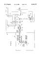
- FIG. 1shows a modular arrangement including microscope M, scanning head S, and laser unit;
- FIG. 2shows the beam path in the scanning head S
- FIG. 3shows the optical effect of the displaceable collimating optics 16
- FIG. 4shows the optical effect of the pinholes which are displaceable in the direction of the optical axis
- FIG. 5shows the optical effect of the pinholes which are displaceable vertically to the optical axis with different reflecting beam splitters
- FIG. 6shows the scanning head S, microscope M, and a fiber behind the pinhole in the detection beam path.
- FIG. 1shows schematically a microscope unit M and a scanning head S which share an optical interface via an intermediate imaging Z according to FIG. 2.
- the scanning head Scan at the photo tube of an upright microscope and also, in an advantageous manner, at a side output of an inverted microscope.
- FIG. 1shows a microscope beam path which is switchable between reflected-light scanning and transmitted-light scanning by means of a swivelable mirror 14, with light source 1, illuminating optics 2, beam splitter 3, objective 4, specimen 5, condenser 5, light source 7, receiver arrangement 8, a first tube lens 9, an observation beam path with a second tube lens 10, and an eyepiece 11, as well as a beam splitter for coupling in the scanning beam.
- a laser module 13.1, 13.2receives the lasers and is connected with the laser coupling-in unit of the scanning head S via light-conducting fibers 14.1, 14.2. Coupling into the light-conducting fibers 14.1, 14.2 is effected by means of displaceable collimating optics 16 which will be discussed in more detail herein, and by means of beam deflecting elements 17.1, 17.2.
- a monitor beam pathis reduced or stopped down in the direction of a monitor diode 19 by means of a partially reflecting mirror 18; line filters 21 and neutral filters 20 are advantageously arranged in front of the monitor diode 19 on a rotatable filter wheel, not shown.
- the actual scanning unitcomprises a scanning objective 22, scanner 23, main beam splitter 24, and shared imaging optics 25 for detection channels 26.1 through 26.4.
- a deflecting prism 27 behind the imaging optics 25reflects the beam coming from the object 5 in the direction of dichroitic beam splitter 28 in the convergent beam path of the imaging optics 25, downstream of which are arranged pinholes 29, one for each detection channel, and emission filters 30 and suitable receiver elements 31 (PMT); the pinholes 29 are adjustable in the direction of the optical axis and vertically thereto and can be varied with respect to diameter.
- the beam splitters 27, 28can be advantageously constructed as a splitter wheel with a plurality of positions so as to be switchable by means of stepping motors.
- UV radiationis advantageously coupled into glass fiber 14.1, preferably a single-mode glass fiber, by means of an AOTF as beam deflector, i.e., when the beam should not fall on the fiber input, it is deflected from the fiber input, e.g., in the direction of a light trap, not shown, by the AOTF.
- an AOTFas beam deflector
- the coupling-in optics 33 for coupling in the laser beamhave lens systems, not shown, for coupling in, the focal length of these lens systems being determined by the beam cross section of the lasers and the numerical aperture required for optimum coupling.
- Provided in the laser module 13.2are single-wavelength and multiple-wavelength lasers which are coupled into one or more fibers individually or jointly via an AOTF.
- coupling incan also be effected via a plurality of fibers simultaneously, their radiation being mixed on the microscope side by color combiners after passing through adapting optics.
- the laser beam emanating divergently from the end of the fibers 14.1, 14.2 at the scanning unit S in FIGS. 2 and 3is collimated to an infinite beam by means of collimating optics 16.
- Thisis advantageously effected by an individual lens which is displaced along the optical axis by means of a control unit 37 which is drivable by a central drive unit 34 and therefore exercises a focussing function in that its distance from the end of the light-conducting fibers 14.1, 14.2 at the scanning unit can be varied by means of the invention.
- FIG. 3ashows the beam configuration for two different wavelengths ⁇ 1, ⁇ 2. Since imaging is effected for a polychromatic light source by stationary imaging optics in an image plane only for a mean wavelength of the spectral region, the spacing of the fiber end and collimating optics is changed by the driving unit 37. Lens positions S1, S2 are given for the two shown wavelengths to ensure the same focus position for both wavelengths. Accordingly, in the case of fluorescence microscopy, the fluorescence radiation occurs in the focus of the objective 4 which is adjusted to infinity and the excitation radiation is focussed in the same plane.
- a plurality of fibers and fiber collimatorscan be used for adjusting different chromatic compensations for different excitation wavelengths. Further, a chromatic correction of the utilized optics, especially of the microscope objective, can be effected in this way.
- Different chromatic compensationscan be adjusted individually for different wavelengths by means of a plurality of coupling-in fibers and collimating optics.
- the variable collimation by means of displacement of the lens 16can also be used to realize z-scanning in that the focus in the specimen is displaced in the z direction by means of the displaceable collimator lens 16 and one optical section after the other is detected. This is shown for a wavelength ⁇ in FIG. 3b, wherein the focus positions F1, F2 correspond to positions S1, S2.
- a monitor diode 19which can also have a focussing lens, not shown, placed in front of it acts in combination with a line-selective or region-selective filter wheel or filter slide 21, driven by a control unit 36 for permanent monitoring of the laser beam coupled into the scanning module, especially to monitor in an isolated manner the output in a determined laser line and, if need be, to stabilize it by means of a regulating signal of the driving unit 34.
- the detection by means of the monitor diode 19includes laser noise and variations due to the mechanical-optical transmission system.
- an error signalcan be derived from the detected instantaneous laser output, which error signal retroacts on-line directly on the laser or on an intensity modulator (ASOM, AOTF, EOM, shutter) connected downstream of the laser for the purpose of stabilizing the laser output radiated into the scanning module.
- a stabilization of intensity with respect to wavelength and a monitoring of laser outputcan accordingly be effected by controlling the filter unit 21.
- a noise reductioncan be effected by taking the signal quotient of and/or by signal subtraction of the detection signal and of the monitor signal of the diode 19 in that the corresponding sensor signal of a detection channel is normalized or standardized (e.g., division) with respect to the signal of the monitor diode by pixel as pixel-frame information in order in this way to reduce intensity fluctuations in the image.
- FIG. 1in a schematic view, shows pinholes 29 in the detection channels 26.1-26.4, which pinholes 29 are adjustable in different ways.
- theycan be arranged so as to be displaceable vertically to the optical axis or in the direction of the optical axis and, in a known manner, so as to be variable in diameter, e.g., by means of a shearing mechanism or cat's eye.
- the adjustment of the pinhole diameterallows them to be adapted to the diameter of the Airy disk at different observation wavelengths.
- FIGS. 4 and 5show schematic views of driving means 38 for the adjustment or displacement of the individual pinholes which have data lines to the central driving unit 34.
- the controllable displacement of the pinhole in the direction of the optical axisis shown schematically in FIG. 4. It is advantageous for compensation of optical errors, especially chromatic longitudinal aberrations. These errors can occur in the scanning objective 22, but also, for example, in the shared imaging optics 25 for the detection channels.
- the imaging optics 25shared by all of the detection channels and advantageously comprising only one optical element, the image at infinity which is generated by the scanning objective 22 is imaged in the pinhole plane.
- the shared imaging optic 25brings about an improved transmission efficiency compared with known solutions. Nevertheless, an exact alignment can be effected in cooperation with the imaging optics with individually adjustable. pinholes in the individual detection channels.
- Different dichroitic beam splitters 28can be used in the beam path, depending on the wavelength that is used, in order to block only these wavelengths and direct them to a detection beam path. Therefore, there are splitter turrets or splitter wheels (not shown) in different beam paths for swiveling in different splitters of the smallest possible size, especially splitter wheels whose wheel axis is inclined by 45° relative to the optical axis so that the splitters are always only displaced in the reflection plane. Since the splitters 28 arranged on the splitter wheels cannot be adjusted exactly alike and variations in their alignment or standard wedge tolerances can cause different beam deflecting angles, the respective pinhole is displaced via control unit 38 vertically to the optical axis corresponding to the beam deflection as is shown in FIG. 5.
- a coupling of the position of the pinhole 29 with the splitter wheel position for the splitters 28can be effected by means of the driving unit 34 via the control units 36, 38, i.e., an optimum pinhole position can be stored and called up for all splitter configurations of different splitter turrets. This applies not only for the position of a determined splitter wheel, but also for the position of a plurality of splitter wheels, so that the respective optimum pinhole position is always set automatically.
- FIG. 6shows schematically how a light-conducting fiber 40 can be placed at the pinhole 29 at the output to the PMT behind the pinhole in order to guide the beam through the pinhole of the detection channel to an external sensor 31. This is advantageously effected without additional coupling optics close behind the pinhole by means of the light-conducting fiber 38. Since the pinhole aperture is adjustable, the exchange of fibers with different core diameters is greatly simplified in that the pinhole size is adapted to the core diameter.
Landscapes
- Physics & Mathematics (AREA)
- Chemical & Material Sciences (AREA)
- Analytical Chemistry (AREA)
- General Physics & Mathematics (AREA)
- Optics & Photonics (AREA)
- Microscoopes, Condenser (AREA)
Abstract
Description
This application claims benefit of provisional appln. 60/055,322 Aug. 11, 1997.
The present invention relates to a laser scanning microscope.
The following represents the prior art.
Handbook of Biological Confocal Microscopy, Second Edition, Plenum Press, New York and London 1995, page 519, FIG. 6: Fiber coupling optics, page 595, FIG. 14: Telecentric system for a plurality of detection beam paths;
U.S. Pat. No. 5,283,433: Coupling optics for detection beam paths;
DE 4323129 A1, column 6: Confocal apertures which can be centered and varied with respect to diameter;
U.S. Pat. No. 5,444,528, U.S. Pat. No. 5,377,003, U.S. Pat. No. 5,317,379, U.S. Pat. No. 5,216,484: AOTF; U.S. Pat. No. 5,081,350, EP 283256 A1, WO 90/00754: Fiber connection between laser and scanning unit.
It is an object to provide an improved laser scanning microscope.
In accordance with the invention, an arrangement and corresponding method are provided for coupling radiation, preferably laser radiation, into a scanning head with a scanning unit in at least two dimensions. The radiation is focussed on an object via a microscope objective via at least one light-conducting fiber which is coupled with the scanning head. A collimator is arranged downstream of the fiber end at the scanning head for collimating the radiation exiting in a divergent manner at the fiber end.
The following detailed description, given by way of example and not intended to limit the present invention solely thereto, will best be appreciated in conjunction with the accompanying drawings, wherein like reference numerals denote like elements and parts, in which:
FIG. 1 shows a modular arrangement including microscope M, scanning head S, and laser unit;
FIG. 2 shows the beam path in the scanning head S;
FIG. 3 shows the optical effect of thedisplaceable collimating optics 16;
FIG. 4 shows the optical effect of the pinholes which are displaceable in the direction of the optical axis;
FIG. 5 shows the optical effect of the pinholes which are displaceable vertically to the optical axis with different reflecting beam splitters; and
FIG. 6 shows the scanning head S, microscope M, and a fiber behind the pinhole in the detection beam path.
M microscope
S scanning head
1 light source
2 illuminating optics
3 beam splitter
4 objective
5 specimen
6 condenser
7 light source
8 receiver
9 tube lens
10 tube lens
11 eyepiece
12 beam splitter
13.1, 13.2 lasers
14 light-conducting fibers
15 swivelable mirror
16 collimating optics
17 beam deflecting element
18 partially reflecting mirror
19 monitor diode
20 neutral filter
21 line filter
22 scanning objective
23 scanner
24 main beam splitter
25 imaging optics
26.1-26.4 detection channels
27 deflecting prism
28, 28.1, 28.2 dichroitic beam splitters
29 adjustable pinholes (pinhole diaphragm)
30 emission filter
31 PMT
32 AOTF
33 coupling-in optics
34 central driving unit
35, 36, 37, 38 local driving units fordiode 19,filter changer 21, collimatingoptics 16,adjustable pinholes 29
39 beam splitter
40 light-conducting fiber
S1, S2, F1, F2 focus positions
P1, P2 pinhole positions
FIG. 1 shows schematically a microscope unit M and a scanning head S which share an optical interface via an intermediate imaging Z according to FIG. 2. The scanning head S can at the photo tube of an upright microscope and also, in an advantageous manner, at a side output of an inverted microscope.
FIG. 1 shows a microscope beam path which is switchable between reflected-light scanning and transmitted-light scanning by means of aswivelable mirror 14, withlight source 1, illuminatingoptics 2,beam splitter 3,objective 4,specimen 5,condenser 5, light source 7,receiver arrangement 8, afirst tube lens 9, an observation beam path with asecond tube lens 10, and aneyepiece 11, as well as a beam splitter for coupling in the scanning beam.
A laser module 13.1, 13.2 receives the lasers and is connected with the laser coupling-in unit of the scanning head S via light-conducting fibers 14.1, 14.2. Coupling into the light-conducting fibers 14.1, 14.2 is effected by means of displaceablecollimating optics 16 which will be discussed in more detail herein, and by means of beam deflecting elements 17.1, 17.2. A monitor beam path is reduced or stopped down in the direction of amonitor diode 19 by means of a partially reflectingmirror 18; line filters 21 andneutral filters 20 are advantageously arranged in front of themonitor diode 19 on a rotatable filter wheel, not shown.
The actual scanning unit comprises ascanning objective 22,scanner 23,main beam splitter 24, and sharedimaging optics 25 for detection channels 26.1 through 26.4. A deflectingprism 27 behind theimaging optics 25 reflects the beam coming from theobject 5 in the direction ofdichroitic beam splitter 28 in the convergent beam path of theimaging optics 25, downstream of which are arrangedpinholes 29, one for each detection channel, andemission filters 30 and suitable receiver elements 31 (PMT); thepinholes 29 are adjustable in the direction of the optical axis and vertically thereto and can be varied with respect to diameter.
As is shown schematically in FIG. 5, thebeam splitters
UV radiation is advantageously coupled into glass fiber 14.1, preferably a single-mode glass fiber, by means of an AOTF as beam deflector, i.e., when the beam should not fall on the fiber input, it is deflected from the fiber input, e.g., in the direction of a light trap, not shown, by the AOTF.
The coupling-inoptics 33 for coupling in the laser beam have lens systems, not shown, for coupling in, the focal length of these lens systems being determined by the beam cross section of the lasers and the numerical aperture required for optimum coupling. Provided in the laser module 13.2 are single-wavelength and multiple-wavelength lasers which are coupled into one or more fibers individually or jointly via an AOTF.
Further, coupling in can also be effected via a plurality of fibers simultaneously, their radiation being mixed on the microscope side by color combiners after passing through adapting optics.
It is also possible to mix the radiation of different lasers at the fiber input; this mixing can be effected by means of thesplitter mirror 39, shown schematically, which is designed so as to be exchangeable and switchable.
The laser beam emanating divergently from the end of the fibers 14.1, 14.2 at the scanning unit S in FIGS. 2 and 3 is collimated to an infinite beam by means of collimatingoptics 16. This is advantageously effected by an individual lens which is displaced along the optical axis by means of acontrol unit 37 which is drivable by acentral drive unit 34 and therefore exercises a focussing function in that its distance from the end of the light-conducting fibers 14.1, 14.2 at the scanning unit can be varied by means of the invention.
The displacement effect of the collimatingoptics 16 is shown schematically in FIGS. 3a and 3b. FIG. 3a shows the beam configuration for two different wavelengths λ1, λ2. Since imaging is effected for a polychromatic light source by stationary imaging optics in an image plane only for a mean wavelength of the spectral region, the spacing of the fiber end and collimating optics is changed by the drivingunit 37. Lens positions S1, S2 are given for the two shown wavelengths to ensure the same focus position for both wavelengths. Accordingly, in the case of fluorescence microscopy, the fluorescence radiation occurs in the focus of theobjective 4 which is adjusted to infinity and the excitation radiation is focussed in the same plane.
Also, a plurality of fibers and fiber collimators can be used for adjusting different chromatic compensations for different excitation wavelengths. Further, a chromatic correction of the utilized optics, especially of the microscope objective, can be effected in this way.
Different chromatic compensations can be adjusted individually for different wavelengths by means of a plurality of coupling-in fibers and collimating optics. The variable collimation by means of displacement of thelens 16 can also be used to realize z-scanning in that the focus in the specimen is displaced in the z direction by means of thedisplaceable collimator lens 16 and one optical section after the other is detected. This is shown for a wavelength λ in FIG. 3b, wherein the focus positions F1, F2 correspond to positions S1, S2.
In FIG. 2, amonitor diode 19 which can also have a focussing lens, not shown, placed in front of it acts in combination with a line-selective or region-selective filter wheel orfilter slide 21, driven by acontrol unit 36 for permanent monitoring of the laser beam coupled into the scanning module, especially to monitor in an isolated manner the output in a determined laser line and, if need be, to stabilize it by means of a regulating signal of the drivingunit 34. The detection by means of themonitor diode 19 includes laser noise and variations due to the mechanical-optical transmission system. In this respect, an error signal can be derived from the detected instantaneous laser output, which error signal retroacts on-line directly on the laser or on an intensity modulator (ASOM, AOTF, EOM, shutter) connected downstream of the laser for the purpose of stabilizing the laser output radiated into the scanning module. A stabilization of intensity with respect to wavelength and a monitoring of laser output can accordingly be effected by controlling thefilter unit 21.
By means of a connection to the detection means 31 (PMT) and to the central driving unit, a noise reduction can be effected by taking the signal quotient of and/or by signal subtraction of the detection signal and of the monitor signal of thediode 19 in that the corresponding sensor signal of a detection channel is normalized or standardized (e.g., division) with respect to the signal of the monitor diode by pixel as pixel-frame information in order in this way to reduce intensity fluctuations in the image.
FIG. 1, in a schematic view, showspinholes 29 in the detection channels 26.1-26.4, which pinholes 29 are adjustable in different ways. In particular, they can be arranged so as to be displaceable vertically to the optical axis or in the direction of the optical axis and, in a known manner, so as to be variable in diameter, e.g., by means of a shearing mechanism or cat's eye. The adjustment of the pinhole diameter allows them to be adapted to the diameter of the Airy disk at different observation wavelengths.
FIGS. 4 and 5 show schematic views of driving means 38 for the adjustment or displacement of the individual pinholes which have data lines to thecentral driving unit 34. The controllable displacement of the pinhole in the direction of the optical axis is shown schematically in FIG. 4. It is advantageous for compensation of optical errors, especially chromatic longitudinal aberrations. These errors can occur in thescanning objective 22, but also, for example, in the sharedimaging optics 25 for the detection channels.
Due to chromatic longitudinal deviations, different focus positions which correspond to different pinhole positions P1, P2 result for different wavelengths λ1, λ2. When exchanging imaging optics, for example, of the microscope objective, an automatic displacement of the pinhole can be effected along the optical axis via the drivingunit 34 and controlling and displacing means 38 with known chromatic longitudinal aberrations of the utilized optics. An exact adjustment to the utilized excitation wavelength can be carried out.
Due to theimaging optics 25 shared by all of the detection channels and advantageously comprising only one optical element, the image at infinity which is generated by thescanning objective 22 is imaged in the pinhole plane. The sharedimaging optic 25 brings about an improved transmission efficiency compared with known solutions. Nevertheless, an exact alignment can be effected in cooperation with the imaging optics with individually adjustable. pinholes in the individual detection channels.
Differentdichroitic beam splitters 28 can be used in the beam path, depending on the wavelength that is used, in order to block only these wavelengths and direct them to a detection beam path. Therefore, there are splitter turrets or splitter wheels (not shown) in different beam paths for swiveling in different splitters of the smallest possible size, especially splitter wheels whose wheel axis is inclined by 45° relative to the optical axis so that the splitters are always only displaced in the reflection plane. Since thesplitters 28 arranged on the splitter wheels cannot be adjusted exactly alike and variations in their alignment or standard wedge tolerances can cause different beam deflecting angles, the respective pinhole is displaced viacontrol unit 38 vertically to the optical axis corresponding to the beam deflection as is shown in FIG. 5. Shown here in a schematic view through different positions are two splitters 28.1, 28.2 on a splitter wheel, not shown, driven by acontrol unit 36, resulting in focus positions in the plane of thepinholes 29 displaced vertically to the optical axis. For this purpose, a coupling of the position of thepinhole 29 with the splitter wheel position for thesplitters 28 can be effected by means of the drivingunit 34 via thecontrol units
FIG. 6 shows schematically how a light-conductingfiber 40 can be placed at thepinhole 29 at the output to the PMT behind the pinhole in order to guide the beam through the pinhole of the detection channel to anexternal sensor 31. This is advantageously effected without additional coupling optics close behind the pinhole by means of the light-conductingfiber 38. Since the pinhole aperture is adjustable, the exchange of fibers with different core diameters is greatly simplified in that the pinhole size is adapted to the core diameter.
While the present invention has been particularly shown and described in conjunction with preferred embodiments thereof it will be readily appreciated by those of ordinary skill in the art that various changes may be made without departing from the spirit and scope of the invention.
Therefore, it is intended that the appended claims be interpreted as including the embodiments described herein, the alternatives mentioned above, and all equivalents thereto.
Claims (5)
1. An arrangement for coupling radiation, preferably laser radiation, into a scanning head with a scanning unit scanning in at least two dimensions, comprising:
a microscope objective for focussing the radiation on an object;
at least one light-conducting fiber coupled with the scanning head, the radiation being focused on the object via said at least one light-conducting fiber; and
a collimator arranged downstream of the fiber end at the scanning head for collimating the radiation exiting in a divergent manner at the fiber end.
2. The arrangement according to claim 1, wherein the collimator is displaceable in order to change its distance from the fiber end.
3. The arrangement according to claim 2, wherein coupling in is effected via a plurality of fibers for different wavelengths and/or wavelength ranges and displaceable collimators are arranged subsequent to each fiber output.
4. A method for the operation of the arrangement according to claim 2, wherein an adjustment of the focus position is effected in a direction vertical to the two-dimensional deflection by means of the displacement of the collimating optics for a wavelength.
5. A method for the operation of the arrangement according to claim 2, wherein a wavelength-dependent displacement of the collimating optics is effected for coupling in radiation of a plurality of wavelengths via a fiber and/or for different chromatic aberrations.
Priority Applications (4)
| Application Number | Priority Date | Filing Date | Title |
|---|---|---|---|
| US09/129,342US6167173A (en) | 1997-01-27 | 1998-08-05 | Laser scanning microscope |
| US09/563,694US6563632B1 (en) | 1997-01-27 | 2000-05-03 | Laser scanning microscope with displaceable confocal diaphragms |
| US09/564,322US6486458B1 (en) | 1997-01-27 | 2000-05-03 | System and method for monitoring the laser radiation coupled into a scanning head in a laser scanning microscope |
| US09/677,685US6631226B1 (en) | 1997-01-27 | 2000-10-02 | Laser scanning microscope |
Applications Claiming Priority (4)
| Application Number | Priority Date | Filing Date | Title |
|---|---|---|---|
| DE1997102753DE19702753C2 (en) | 1997-01-27 | 1997-01-27 | Laser Scanning Microscope |
| DE19702753 | 1997-01-27 | ||
| US5532297P | 1997-08-11 | 1997-08-11 | |
| US09/129,342US6167173A (en) | 1997-01-27 | 1998-08-05 | Laser scanning microscope |
Related Child Applications (3)
| Application Number | Title | Priority Date | Filing Date |
|---|---|---|---|
| US09/563,694DivisionUS6563632B1 (en) | 1997-01-27 | 2000-05-03 | Laser scanning microscope with displaceable confocal diaphragms |
| US09/564,322DivisionUS6486458B1 (en) | 1997-01-27 | 2000-05-03 | System and method for monitoring the laser radiation coupled into a scanning head in a laser scanning microscope |
| US09/677,685DivisionUS6631226B1 (en) | 1997-01-27 | 2000-10-02 | Laser scanning microscope |
Publications (1)
| Publication Number | Publication Date |
|---|---|
| US6167173Atrue US6167173A (en) | 2000-12-26 |
Family
ID=27217062
Family Applications (3)
| Application Number | Title | Priority Date | Filing Date |
|---|---|---|---|
| US09/129,342Expired - LifetimeUS6167173A (en) | 1997-01-27 | 1998-08-05 | Laser scanning microscope |
| US09/564,322Expired - Fee RelatedUS6486458B1 (en) | 1997-01-27 | 2000-05-03 | System and method for monitoring the laser radiation coupled into a scanning head in a laser scanning microscope |
| US09/563,694Expired - Fee RelatedUS6563632B1 (en) | 1997-01-27 | 2000-05-03 | Laser scanning microscope with displaceable confocal diaphragms |
Family Applications After (2)
| Application Number | Title | Priority Date | Filing Date |
|---|---|---|---|
| US09/564,322Expired - Fee RelatedUS6486458B1 (en) | 1997-01-27 | 2000-05-03 | System and method for monitoring the laser radiation coupled into a scanning head in a laser scanning microscope |
| US09/563,694Expired - Fee RelatedUS6563632B1 (en) | 1997-01-27 | 2000-05-03 | Laser scanning microscope with displaceable confocal diaphragms |
Country Status (1)
| Country | Link |
|---|---|
| US (3) | US6167173A (en) |
Cited By (72)
| Publication number | Priority date | Publication date | Assignee | Title |
|---|---|---|---|---|
| US6278555B1 (en)* | 1998-07-04 | 2001-08-21 | Carl Zeiss Jena Gmbh | Laser scanning microscope |
| US6437913B1 (en)* | 1999-03-18 | 2002-08-20 | Olympus Optical Co., Ltd. | Laser microscope |
| US20020176162A1 (en)* | 2000-07-17 | 2002-11-28 | Rolf Borlinghaus | Arrangement for spectrally sensitive reflected-light and transmitted-light microscopy |
| US20030030897A1 (en)* | 2001-08-09 | 2003-02-13 | Olympus Optical Co., Ltd. | Laser microscope |
| US6521899B1 (en) | 1999-04-27 | 2003-02-18 | Carl Zeiss Jena Gmbh | Arrangement for the adjustment of laser power and/or pulse length of a short pulse laser in a microscope |
| US20030067607A1 (en)* | 2001-10-09 | 2003-04-10 | Ralf Wolleschensky | Method and arrangement for the depth-resolved detection of specimens |
| US20030107732A1 (en)* | 2001-10-03 | 2003-06-12 | Olympus Optical Co., Ltd. | Laser scanning microscope |
| EP1355182A1 (en)* | 2002-04-17 | 2003-10-22 | CARL ZEISS JENA GmbH | Microscope with an optical filter identification unit |
| US6686583B2 (en)* | 2000-07-10 | 2004-02-03 | Leica Mircrosystems Heidelberg Gmbh | Apparatus for coupling light into an optical assemblage and confocal scanning microscope |
| US20040051941A1 (en)* | 2002-04-17 | 2004-03-18 | Johannes Winterot | Laser-scanning microscope with collimator and/or pinhole optics |
| US20040061073A1 (en)* | 2002-06-24 | 2004-04-01 | Olympus Optical Co., Ltd. | Laser scanning microscope, semiconductor laser light source unit, scanning unit for a laser scanning microscope, and method of connecting semiconductor light source to scanning microscope |
| US20040178356A1 (en)* | 2002-08-29 | 2004-09-16 | Olympus Optical Co., Ltd. | Laser scanning microscope |
| US20040190133A1 (en)* | 2001-04-26 | 2004-09-30 | Leica Microsystems Heidelberg Gmbh | Scanning microscope and coupling-out element |
| WO2004104522A1 (en)* | 2003-05-22 | 2004-12-02 | Carl Zeiss Jena Gmbh | Adjustable pinhole in particular for a laser-scanning microscope |
| US6888118B2 (en)* | 2000-06-19 | 2005-05-03 | Leica Microsystems Heidelberg Gmbh | Method, apparatus and scanning microscope with means for stabilizing the temperature of optical components |
| US20060012869A1 (en)* | 2004-07-16 | 2006-01-19 | Ralf Wolleschensky | Light grid microscope with linear scanning |
| US20060012870A1 (en)* | 2004-07-16 | 2006-01-19 | Ralf Engelmann | Light scanning microscope with line-by-line scanning and use |
| US20060012874A1 (en)* | 2004-07-16 | 2006-01-19 | Joerg-Michael Funk | Raster scanning light microscope with punctiform light source distribution and applications |
| US20060011803A1 (en)* | 2004-07-16 | 2006-01-19 | Ralf Wolleschensky | Light raster microscope with sampling in the form of a line and its use |
| US20060012862A1 (en)* | 2004-07-16 | 2006-01-19 | Ralf Engelmann | Light scanning microscope point-shaped light source distribution and use |
| US20060012871A1 (en)* | 2004-07-16 | 2006-01-19 | Joerg-Michael Funk | Light scanning electron microscope and use |
| US20060012864A1 (en)* | 2004-07-16 | 2006-01-19 | Joerg-Michael Funk | Raster scanning light microscope with line pattern scanning and applications |
| US20060012875A1 (en)* | 2004-07-16 | 2006-01-19 | Ralf Wolleschensky | Microscope with increased resolution |
| US20060011859A1 (en)* | 2004-07-16 | 2006-01-19 | Ralf Wolleschensky | Procedure for the optical acquisition of objects by means of a light raster microscope |
| US20060011861A1 (en)* | 2004-07-16 | 2006-01-19 | Ralf Wolleschensky | Procedure for the optical acquisition of objects by means of a light raster microscope |
| US20060011832A1 (en)* | 2004-07-16 | 2006-01-19 | Ralf Wolleschensky | Optical zoom system for a light scanning electron microscope |
| US20060012785A1 (en)* | 2004-07-16 | 2006-01-19 | Joerg-Michael Funk | Light scanning electron microscope and use |
| US20060011822A1 (en)* | 2004-07-16 | 2006-01-19 | Frank Hecht | Light scanning microscope and use |
| US20060012856A1 (en)* | 2004-07-16 | 2006-01-19 | Ralf Wolleschensky | Light raster microscope with light distribution in the form of a point and its use |
| US20060028718A1 (en)* | 2002-07-12 | 2006-02-09 | Olympus Biosystems Gmbh | Illuminating device and optical object-analyzing device |
| US20060049343A1 (en)* | 2004-07-16 | 2006-03-09 | Ralf Wolleschensky | Optical zoom system for a light scanning electron microscope |
| US20060165359A1 (en)* | 2003-07-15 | 2006-07-27 | Kyra Mollmann | Light source with a microstructured optica element and miroscope with a light source |
| US20060214106A1 (en)* | 2005-03-01 | 2006-09-28 | Ralf Wolleschensky | Point scanning laser scanning microscope and methods for adjustment of a microscope |
| WO2006102971A2 (en) | 2005-03-26 | 2006-10-05 | Carl Zeiss Meditec Ag | Scanning device |
| US20060255237A1 (en)* | 2003-07-11 | 2006-11-16 | Thomas Mehner | Arrangement for the detection of illumination radiation in a laser scanning microscope |
| US20060256426A1 (en)* | 2005-05-03 | 2006-11-16 | Ralf Wolleschensky | Device for controlling light radiation |
| US20060273261A1 (en)* | 2005-05-03 | 2006-12-07 | Ralf Wolleschensky | Laser scanning microscope |
| US20070019192A1 (en)* | 2005-05-03 | 2007-01-25 | Helmut Bloos | Laser scanning microscope |
| US7187493B2 (en)* | 2000-10-31 | 2007-03-06 | Olympus Optical Co., Ltd. | Laser microscope |
| US20070076293A1 (en)* | 2004-07-16 | 2007-04-05 | Ralf Wolleschensky | Optical zoom system for a light scanning electron microscope |
| US20070121473A1 (en)* | 2003-10-30 | 2007-05-31 | Carl Zeiss Jena Gmbh | Laser scanning microscope with a non-descanned detection and/or observation beam path |
| US20070159689A1 (en)* | 2004-03-31 | 2007-07-12 | Dieter Schau | Tube-type revolver with at least four positions for injecting or extracting light into or from a laser scanning microscope |
| JP2007183111A (en)* | 2006-01-04 | 2007-07-19 | Nikon Corp | Light intensity detection device, optical device having the same, and microscope |
| US20070178602A1 (en)* | 2003-06-16 | 2007-08-02 | Ralf Wolleschensky | Method to be used in fluoresence microscopy |
| US20070242268A1 (en)* | 2006-04-15 | 2007-10-18 | Hans-Juergen Dobschal | Spectral analytical unit with a diffraction grating |
| US20070279734A1 (en)* | 2001-02-16 | 2007-12-06 | Evotec Ag | Microscope |
| JP2008033263A (en)* | 2006-07-28 | 2008-02-14 | Carl Zeiss Microimaging Gmbh | Scanning laser microscope for fluorescence inspection |
| US20080049221A1 (en)* | 2002-09-04 | 2008-02-28 | Ralf Wolleschensky | Method and arrangement for changing the spectral composition and/or intensity of illumination light and/or specimen light in an adjustable manner |
| US20080055579A1 (en)* | 2006-09-05 | 2008-03-06 | Joshua Monroe Cobb | Optical power modulation at high frequency |
| US20090046360A1 (en)* | 2004-07-16 | 2009-02-19 | Joerg-Michael Funk | Raster scanning light microscope with line pattern scanning and applications |
| US7586961B2 (en) | 2005-09-28 | 2009-09-08 | Point Source Limited | Laser systems |
| US7605976B1 (en) | 2005-05-03 | 2009-10-20 | Carl Zeiss Microimaging Gmbh | Method and device for changing light in an adjustable manner |
| US20090303583A1 (en)* | 2005-05-03 | 2009-12-10 | Heinrich Klose | Device and method for the reproducible adjustment of the pin hole opening and pin hole position in laser scanning microscopes |
| US20100027108A1 (en)* | 2007-02-21 | 2010-02-04 | Stefan Wilhelm | Confocal laser microscope |
| US20100182683A1 (en)* | 2007-10-31 | 2010-07-22 | Nikon Corporation | Laser excitation fluorescent microscope |
| US20100214653A1 (en)* | 2007-08-16 | 2010-08-26 | Joerg Pacholik | Microscope having internal focusing |
| US20110141557A1 (en)* | 2006-12-22 | 2011-06-16 | Nikon Corporation | Laser scan confocal microscope |
| JP2012133368A (en)* | 2010-12-22 | 2012-07-12 | Carl Zeiss Microimaging Gmbh | Pin hole of confocal laser scanning microscope |
| EP2201351B1 (en)* | 2007-09-28 | 2013-11-06 | Magyar Tudományos Akadémia | Laser-scanning microscope with a differential polarization measuring extension unit |
| DE102012019472A1 (en) | 2012-09-28 | 2014-04-03 | Carl Zeiss Microscopy Gmbh | Optical filter device, in particular for microscopes |
| US8879072B2 (en) | 2011-03-08 | 2014-11-04 | Carl Zeiss Microscopy Gmbh | Laser scanning microscope and method for operation thereof |
| DE102014008098A1 (en) | 2014-05-31 | 2015-12-03 | Carl Zeiss Ag | Spectrally flexible, fast-switching optical filter device |
| WO2016116424A3 (en)* | 2015-01-19 | 2016-09-15 | Carl Zeiss Ag | Optical arrangement for a laser scanner system |
| JP2016197266A (en)* | 2016-08-15 | 2016-11-24 | オリンパス株式会社 | Microscope equipment |
| CN106461926A (en)* | 2014-04-17 | 2017-02-22 | 卡尔蔡司股份公司 | Light scanning microscope with simplified optics, in particular with variable pupil position |
| US9645376B1 (en) | 2015-10-14 | 2017-05-09 | Abberior Instruments Gmbh | Scanner head and device with scanner head |
| US20170285316A1 (en)* | 2014-12-23 | 2017-10-05 | Chengdu Westimage Technology Co., Ltd | Polarizing device for polarizing microscopes and method for using the polarizing device |
| CN109073875A (en)* | 2016-05-02 | 2018-12-21 | 卡尔蔡司显微镜有限责任公司 | Lighting module for illuminating angle may be selected |
| CN110268299A (en)* | 2016-11-12 | 2019-09-20 | 凯利博成像和诊断公司 | With the confocal microscope that may be positioned to as head |
| US10884227B2 (en) | 2016-11-10 | 2021-01-05 | The Trustees Of Columbia University In The City Of New York | Rapid high-resolution imaging methods for large samples |
| US11493744B2 (en) | 2019-06-19 | 2022-11-08 | Abberior Instruments Gmbh | Methods and apparatuses for checking the confocality of a scanning and descanning microscope assembly |
| US12216019B2 (en) | 2021-12-22 | 2025-02-04 | Abberior Instruments Gmbh | Apparatuses for testing the lateral and axial confocality of a scanning and descanning microscope component group |
Families Citing this family (21)
| Publication number | Priority date | Publication date | Assignee | Title |
|---|---|---|---|---|
| EP1145066B1 (en)* | 1998-12-21 | 2005-03-02 | Evotec OAI AG | Scanning microscopic method having high axial resolution |
| JP4812179B2 (en)* | 2001-03-13 | 2011-11-09 | オリンパス株式会社 | Laser microscope |
| DE10151216A1 (en)* | 2001-10-16 | 2003-04-24 | Zeiss Carl Jena Gmbh | Method for the optical detection of characteristic quantities of an illuminated sample |
| DE10332074A1 (en)* | 2003-07-11 | 2005-02-10 | Carl Zeiss Jena Gmbh | Arrangement for the direct coupling of a laser, preferably a short pulse laser |
| DE10332062A1 (en)* | 2003-07-11 | 2005-01-27 | Carl Zeiss Jena Gmbh | Arrangement in the illumination beam path of a laser scanning microscope |
| DE20319495U1 (en)* | 2003-12-16 | 2004-03-11 | Carl Zeiss Jena Gmbh | Illumination device for a microscope |
| US7233437B2 (en)* | 2004-03-25 | 2007-06-19 | Olympus Corporation | Laser-scanning microscope |
| US7190514B2 (en)* | 2004-08-12 | 2007-03-13 | Yokogawa Electric Corporation | Confocal scanning microscope |
| EP1657580A1 (en)* | 2004-11-11 | 2006-05-17 | Eldim Sa | Optical device for determining the in-focus position of a fourier optics set-up |
| JP2006208681A (en)* | 2005-01-27 | 2006-08-10 | Olympus Corp | Connection unit and optical scanning type fluorescent observation device |
| DE102005054184B4 (en)* | 2005-11-14 | 2020-10-29 | Carl Zeiss Microscopy Gmbh | Multispectral lighting device and measuring method |
| DE102006034908B4 (en)* | 2006-07-28 | 2023-01-26 | Carl Zeiss Microscopy Gmbh | Laser Scanning Microscope |
| US8797644B2 (en)* | 2006-08-11 | 2014-08-05 | The Regents Of The University Of California | Capillary-based cell and tissue acquisition system (CTAS) |
| DE102007007655A1 (en)* | 2007-02-13 | 2008-08-14 | Leica Microsystems Cms Gmbh | microscope |
| WO2009020161A1 (en) | 2007-08-07 | 2009-02-12 | Nikon Corporation | Microscope |
| CA2741734C (en) | 2008-11-18 | 2017-07-18 | Stryker Corporation | Endoscopic led light source having a feedback control system |
| US8275226B2 (en)* | 2008-12-09 | 2012-09-25 | Spectral Applied Research Ltd. | Multi-mode fiber optically coupling a radiation source module to a multi-focal confocal microscope |
| DE102009034347A1 (en) | 2009-07-23 | 2011-01-27 | Carl Zeiss Microlmaging Gmbh | Adjustment element for setting the pinhole position |
| EP2510395B1 (en)* | 2009-12-08 | 2015-09-09 | Spectral Applied Research Inc. | Imaging distal end of multimode fiber |
| US10687697B2 (en) | 2013-03-15 | 2020-06-23 | Stryker Corporation | Endoscopic light source and imaging system |
| US10690904B2 (en) | 2016-04-12 | 2020-06-23 | Stryker Corporation | Multiple imaging modality light source |
Citations (6)
| Publication number | Priority date | Publication date | Assignee | Title |
|---|---|---|---|---|
| US3639067A (en)* | 1970-06-29 | 1972-02-01 | Emhart Corp | Glassware inspection apparatus employing fiber-optic guides |
| US4337531A (en)* | 1980-05-12 | 1982-06-29 | Northern Telecom Limited | Scanning head for an optical disc system |
| US5179276A (en)* | 1991-03-27 | 1993-01-12 | Fuji Photo Film Co., Ltd. | Optical scanning type image pickup apparatus and optical scanning type microscope |
| US5491550A (en)* | 1990-08-31 | 1996-02-13 | Commonwealth Scientific And Industrial Research Organization | Interference methods and interference microscopes for measuring energy path length differences, path length between two locaitons or for determiing refractive index |
| US5570186A (en)* | 1992-04-28 | 1996-10-29 | Mtu Motoren- Und Turbinen-Union Munich Gmbh | Method for inspecting the curvature of a profile, such an edge of a turbine blade |
| US6023348A (en)* | 1994-10-18 | 2000-02-08 | Howtek, Inc. | Rotary image scanner capable of mounting drums of various diameters |
Family Cites Families (10)
| Publication number | Priority date | Publication date | Assignee | Title |
|---|---|---|---|---|
| EP0283256A3 (en) | 1987-03-18 | 1990-02-07 | Tektronix Inc. | Scanning optical microscope |
| US5386112A (en)* | 1990-06-29 | 1995-01-31 | Dixon; Arthur E. | Apparatus and method for transmitted-light and reflected-light imaging |
| US5548661A (en)* | 1991-07-12 | 1996-08-20 | Price; Jeffrey H. | Operator independent image cytometer |
| JP2511391B2 (en)* | 1991-12-04 | 1996-06-26 | シーメンス アクチエンゲゼルシヤフト | Optical distance sensor |
| US5345338A (en)* | 1992-03-30 | 1994-09-06 | Minolta Camera Kabushiki Kaisha | Zoom lens system for use in a copying apparatus |
| US5535052A (en)* | 1992-07-24 | 1996-07-09 | Carl-Zeiss-Stiftung | Laser microscope |
| US5578832A (en)* | 1994-09-02 | 1996-11-26 | Affymetrix, Inc. | Method and apparatus for imaging a sample on a device |
| GB2290411A (en) | 1994-06-15 | 1995-12-20 | Zeiss Stiftung | Laser and adapter for mounting it on a surgical microscope |
| JPH10506457A (en)* | 1994-07-28 | 1998-06-23 | ジェネラル ナノテクノロジー エルエルシー | Scanning probe microscope equipment |
| US5896224A (en)* | 1994-08-30 | 1999-04-20 | Carl-Zeiss-Stiftung | Confocal microscope with a diaphragm disc having many transparent regions |
- 1998
- 1998-08-05USUS09/129,342patent/US6167173A/ennot_activeExpired - Lifetime
- 2000
- 2000-05-03USUS09/564,322patent/US6486458B1/ennot_activeExpired - Fee Related
- 2000-05-03USUS09/563,694patent/US6563632B1/ennot_activeExpired - Fee Related
Patent Citations (6)
| Publication number | Priority date | Publication date | Assignee | Title |
|---|---|---|---|---|
| US3639067A (en)* | 1970-06-29 | 1972-02-01 | Emhart Corp | Glassware inspection apparatus employing fiber-optic guides |
| US4337531A (en)* | 1980-05-12 | 1982-06-29 | Northern Telecom Limited | Scanning head for an optical disc system |
| US5491550A (en)* | 1990-08-31 | 1996-02-13 | Commonwealth Scientific And Industrial Research Organization | Interference methods and interference microscopes for measuring energy path length differences, path length between two locaitons or for determiing refractive index |
| US5179276A (en)* | 1991-03-27 | 1993-01-12 | Fuji Photo Film Co., Ltd. | Optical scanning type image pickup apparatus and optical scanning type microscope |
| US5570186A (en)* | 1992-04-28 | 1996-10-29 | Mtu Motoren- Und Turbinen-Union Munich Gmbh | Method for inspecting the curvature of a profile, such an edge of a turbine blade |
| US6023348A (en)* | 1994-10-18 | 2000-02-08 | Howtek, Inc. | Rotary image scanner capable of mounting drums of various diameters |
Cited By (120)
| Publication number | Priority date | Publication date | Assignee | Title |
|---|---|---|---|---|
| US6278555B1 (en)* | 1998-07-04 | 2001-08-21 | Carl Zeiss Jena Gmbh | Laser scanning microscope |
| US6437913B1 (en)* | 1999-03-18 | 2002-08-20 | Olympus Optical Co., Ltd. | Laser microscope |
| US6521899B1 (en) | 1999-04-27 | 2003-02-18 | Carl Zeiss Jena Gmbh | Arrangement for the adjustment of laser power and/or pulse length of a short pulse laser in a microscope |
| US6888118B2 (en)* | 2000-06-19 | 2005-05-03 | Leica Microsystems Heidelberg Gmbh | Method, apparatus and scanning microscope with means for stabilizing the temperature of optical components |
| US6686583B2 (en)* | 2000-07-10 | 2004-02-03 | Leica Mircrosystems Heidelberg Gmbh | Apparatus for coupling light into an optical assemblage and confocal scanning microscope |
| US20020176162A1 (en)* | 2000-07-17 | 2002-11-28 | Rolf Borlinghaus | Arrangement for spectrally sensitive reflected-light and transmitted-light microscopy |
| US7075716B2 (en)* | 2000-07-17 | 2006-07-11 | Leica Microsystems Cms Gmbh | Arrangement for spectrally sensitive reflected-light and transmitted-light microscopy |
| US7187493B2 (en)* | 2000-10-31 | 2007-03-06 | Olympus Optical Co., Ltd. | Laser microscope |
| US20070279734A1 (en)* | 2001-02-16 | 2007-12-06 | Evotec Ag | Microscope |
| US6977773B2 (en)* | 2001-04-26 | 2005-12-20 | Leica Microsystems Heidelberg Gmbh | Scanning microscope and coupling-out element |
| US20040190133A1 (en)* | 2001-04-26 | 2004-09-30 | Leica Microsystems Heidelberg Gmbh | Scanning microscope and coupling-out element |
| US20030030897A1 (en)* | 2001-08-09 | 2003-02-13 | Olympus Optical Co., Ltd. | Laser microscope |
| US6674573B2 (en)* | 2001-08-09 | 2004-01-06 | Olympus Optical Co., Ltd. | Laser microscope |
| US6963398B2 (en)* | 2001-10-03 | 2005-11-08 | Olympus Optical Co., Ltd. | Laser scanning microscope |
| US20030107732A1 (en)* | 2001-10-03 | 2003-06-12 | Olympus Optical Co., Ltd. | Laser scanning microscope |
| US20030067607A1 (en)* | 2001-10-09 | 2003-04-10 | Ralf Wolleschensky | Method and arrangement for the depth-resolved detection of specimens |
| EP1302803A3 (en)* | 2001-10-09 | 2004-04-28 | CARL ZEISS JENA GmbH | Method and arrangement for high resolution optical detection of samples |
| US20040156053A1 (en)* | 2001-10-09 | 2004-08-12 | Carl Zeiss Jena Gmbh | Method and arrangement for the depth-resolved detection of specimens |
| US7324271B2 (en)* | 2002-04-17 | 2008-01-29 | Carl Zeiss Jena Gmbh | Laser-scanning microscope with collimator and/or pinhole optics |
| US20030231384A1 (en)* | 2002-04-17 | 2003-12-18 | Gunter Moehler | Microscope with position detection of changers of optical components |
| US7145652B2 (en) | 2002-04-17 | 2006-12-05 | Carl Zeiss Jena Gmbh | Microscope with position detection of changers of optical components |
| EP1355182A1 (en)* | 2002-04-17 | 2003-10-22 | CARL ZEISS JENA GmbH | Microscope with an optical filter identification unit |
| US20040051941A1 (en)* | 2002-04-17 | 2004-03-18 | Johannes Winterot | Laser-scanning microscope with collimator and/or pinhole optics |
| US7015485B2 (en) | 2002-06-24 | 2006-03-21 | Olympus Optical Co., Ltd. | Laser scanning microscope, semiconductor laser light source unit, scanning unit for a laser scanning microscope, and method of connecting semiconductor light source to scanning microscope |
| US20040061073A1 (en)* | 2002-06-24 | 2004-04-01 | Olympus Optical Co., Ltd. | Laser scanning microscope, semiconductor laser light source unit, scanning unit for a laser scanning microscope, and method of connecting semiconductor light source to scanning microscope |
| US7262910B2 (en) | 2002-07-12 | 2007-08-28 | Olympus Biosystems Gmbh | Illuminating device and optical object-analyzing device |
| US20060028718A1 (en)* | 2002-07-12 | 2006-02-09 | Olympus Biosystems Gmbh | Illuminating device and optical object-analyzing device |
| US20040178356A1 (en)* | 2002-08-29 | 2004-09-16 | Olympus Optical Co., Ltd. | Laser scanning microscope |
| US7223986B2 (en)* | 2002-08-29 | 2007-05-29 | Olympus Optical Co., Ltd. | Laser scanning microscope |
| US7701632B2 (en) | 2002-09-04 | 2010-04-20 | Carl Zeiss Microimaging Gmbh | Method and arrangement for changing the spectral composition and/or intensity of illumination light and/or specimen light in an adjustable manner |
| US20080049221A1 (en)* | 2002-09-04 | 2008-02-28 | Ralf Wolleschensky | Method and arrangement for changing the spectral composition and/or intensity of illumination light and/or specimen light in an adjustable manner |
| WO2004104522A1 (en)* | 2003-05-22 | 2004-12-02 | Carl Zeiss Jena Gmbh | Adjustable pinhole in particular for a laser-scanning microscope |
| JP2007505363A (en)* | 2003-05-22 | 2007-03-08 | カール ツァイス イエナ ゲゼルシャフト ミット ベシュレンクテル ハフツング | Adjustable pinhole, especially for laser scanning microscopes |
| US20070178602A1 (en)* | 2003-06-16 | 2007-08-02 | Ralf Wolleschensky | Method to be used in fluoresence microscopy |
| US7688442B2 (en) | 2003-06-16 | 2010-03-30 | Carl Zeiss Microimaging Gmbh | Method to be used in fluorescence microscopy |
| US7498561B2 (en)* | 2003-07-11 | 2009-03-03 | Carl Zeiss Microimaging Gmbh | Arrangement for the detection of illumination radiation in a laser scanning microscope |
| US20060255237A1 (en)* | 2003-07-11 | 2006-11-16 | Thomas Mehner | Arrangement for the detection of illumination radiation in a laser scanning microscope |
| US20060165359A1 (en)* | 2003-07-15 | 2006-07-27 | Kyra Mollmann | Light source with a microstructured optica element and miroscope with a light source |
| US20070121473A1 (en)* | 2003-10-30 | 2007-05-31 | Carl Zeiss Jena Gmbh | Laser scanning microscope with a non-descanned detection and/or observation beam path |
| US20070159689A1 (en)* | 2004-03-31 | 2007-07-12 | Dieter Schau | Tube-type revolver with at least four positions for injecting or extracting light into or from a laser scanning microscope |
| US7304280B2 (en) | 2004-07-16 | 2007-12-04 | Carl Zeiss Jena Gmbh | Laser line scanning microscope and method of use |
| US20060012862A1 (en)* | 2004-07-16 | 2006-01-19 | Ralf Engelmann | Light scanning microscope point-shaped light source distribution and use |
| US20080149818A1 (en)* | 2004-07-16 | 2008-06-26 | Ralf Wolleschensky | Procedure for the optical acquisition of objects by means of a light raster microscope with line by line scanning |
| US20060208178A1 (en)* | 2004-07-16 | 2006-09-21 | Carl Zeiss Jena Gmbh | Light scanning microscope and use |
| USRE43702E1 (en) | 2004-07-16 | 2012-10-02 | Carl Zeiss Microimaging Gmbh | Microscope with heightened resolution and linear scanning |
| US20060049343A1 (en)* | 2004-07-16 | 2006-03-09 | Ralf Wolleschensky | Optical zoom system for a light scanning electron microscope |
| US20060012869A1 (en)* | 2004-07-16 | 2006-01-19 | Ralf Wolleschensky | Light grid microscope with linear scanning |
| US20060012870A1 (en)* | 2004-07-16 | 2006-01-19 | Ralf Engelmann | Light scanning microscope with line-by-line scanning and use |
| US20060012856A1 (en)* | 2004-07-16 | 2006-01-19 | Ralf Wolleschensky | Light raster microscope with light distribution in the form of a point and its use |
| US20060011822A1 (en)* | 2004-07-16 | 2006-01-19 | Frank Hecht | Light scanning microscope and use |
| US20070076293A1 (en)* | 2004-07-16 | 2007-04-05 | Ralf Wolleschensky | Optical zoom system for a light scanning electron microscope |
| US20060012785A1 (en)* | 2004-07-16 | 2006-01-19 | Joerg-Michael Funk | Light scanning electron microscope and use |
| US20060011832A1 (en)* | 2004-07-16 | 2006-01-19 | Ralf Wolleschensky | Optical zoom system for a light scanning electron microscope |
| US7235777B2 (en) | 2004-07-16 | 2007-06-26 | Carl Zeiss Jena Gmbh | Light scanning microscope and use |
| US20060011861A1 (en)* | 2004-07-16 | 2006-01-19 | Ralf Wolleschensky | Procedure for the optical acquisition of objects by means of a light raster microscope |
| US7369305B2 (en) | 2004-07-16 | 2008-05-06 | Carl Zeiss Jena Gmbh | Optical zoom system for a light scanning electron microscope |
| US20070171519A1 (en)* | 2004-07-16 | 2007-07-26 | Ralf Wolleschensky | Microscope with heightened resolution and linear scanning |
| US20060011859A1 (en)* | 2004-07-16 | 2006-01-19 | Ralf Wolleschensky | Procedure for the optical acquisition of objects by means of a light raster microscope |
| US20060012875A1 (en)* | 2004-07-16 | 2006-01-19 | Ralf Wolleschensky | Microscope with increased resolution |
| US7561326B2 (en) | 2004-07-16 | 2009-07-14 | Carl Zeiss Microimaging Gmbh | Light scanning microscope and use |
| US20060012864A1 (en)* | 2004-07-16 | 2006-01-19 | Joerg-Michael Funk | Raster scanning light microscope with line pattern scanning and applications |
| US20060012871A1 (en)* | 2004-07-16 | 2006-01-19 | Joerg-Michael Funk | Light scanning electron microscope and use |
| US7468834B2 (en) | 2004-07-16 | 2008-12-23 | Carl Zeiss Microimaging Gmbh | Microscope with heightened resolution and linear scanning |
| US7323679B2 (en) | 2004-07-16 | 2008-01-29 | Carl Zeiss Jena Gmbh | Procedure for the optical acquisition of objects by means of a light raster microscope with line by line scanning |
| US20060012874A1 (en)* | 2004-07-16 | 2006-01-19 | Joerg-Michael Funk | Raster scanning light microscope with punctiform light source distribution and applications |
| US20080048105A1 (en)* | 2004-07-16 | 2008-02-28 | Carl Zeiss Jena Gmbh | Procedure for the optical acquisition of objects by means of a light raster microscope |
| US20060011803A1 (en)* | 2004-07-16 | 2006-01-19 | Ralf Wolleschensky | Light raster microscope with sampling in the form of a line and its use |
| US20090046360A1 (en)* | 2004-07-16 | 2009-02-19 | Joerg-Michael Funk | Raster scanning light microscope with line pattern scanning and applications |
| US7488931B2 (en) | 2004-07-16 | 2009-02-10 | Carl Zeiss Jena Gmbh | Optical zoom system for a light scanning electron microscope |
| US20060214106A1 (en)* | 2005-03-01 | 2006-09-28 | Ralf Wolleschensky | Point scanning laser scanning microscope and methods for adjustment of a microscope |
| WO2006102971A2 (en) | 2005-03-26 | 2006-10-05 | Carl Zeiss Meditec Ag | Scanning device |
| US20090303583A1 (en)* | 2005-05-03 | 2009-12-10 | Heinrich Klose | Device and method for the reproducible adjustment of the pin hole opening and pin hole position in laser scanning microscopes |
| US20080088907A1 (en)* | 2005-05-03 | 2008-04-17 | Ralf Wolleschensky | Device for controlling light radiation |
| US8759745B2 (en)* | 2005-05-03 | 2014-06-24 | Carl Zeiss Microscopy Gmbh | Device for the reproducible adjustment of a pin hole opening and pin hole position in laser scanning microscopes using a reflector |
| US20060256426A1 (en)* | 2005-05-03 | 2006-11-16 | Ralf Wolleschensky | Device for controlling light radiation |
| US20060273261A1 (en)* | 2005-05-03 | 2006-12-07 | Ralf Wolleschensky | Laser scanning microscope |
| US20070019192A1 (en)* | 2005-05-03 | 2007-01-25 | Helmut Bloos | Laser scanning microscope |
| US7605976B1 (en) | 2005-05-03 | 2009-10-20 | Carl Zeiss Microimaging Gmbh | Method and device for changing light in an adjustable manner |
| US7586961B2 (en) | 2005-09-28 | 2009-09-08 | Point Source Limited | Laser systems |
| JP2007183111A (en)* | 2006-01-04 | 2007-07-19 | Nikon Corp | Light intensity detection device, optical device having the same, and microscope |
| US7852474B2 (en) | 2006-04-15 | 2010-12-14 | Carl Zeiss Microimaging Gmbh | Spectral analysis unit with a diffraction grating |
| US20070242268A1 (en)* | 2006-04-15 | 2007-10-18 | Hans-Juergen Dobschal | Spectral analytical unit with a diffraction grating |
| JP2008033263A (en)* | 2006-07-28 | 2008-02-14 | Carl Zeiss Microimaging Gmbh | Scanning laser microscope for fluorescence inspection |
| US20080055579A1 (en)* | 2006-09-05 | 2008-03-06 | Joshua Monroe Cobb | Optical power modulation at high frequency |
| US7706420B2 (en)* | 2006-09-05 | 2010-04-27 | Corning Incorporated | Optical power modulation at high frequency |
| US8786945B2 (en) | 2006-12-22 | 2014-07-22 | Nikon Corporation | Laser scan confocal microscope |
| US20110141557A1 (en)* | 2006-12-22 | 2011-06-16 | Nikon Corporation | Laser scan confocal microscope |
| US9645373B2 (en) | 2006-12-22 | 2017-05-09 | Nikon Corporation | Laser scan confocal microscope |
| US8400709B2 (en)* | 2006-12-22 | 2013-03-19 | Nikon, Corporation | Laser scan confocal microscope |
| US8477418B2 (en)* | 2007-02-21 | 2013-07-02 | Carl Zeiss Microscopy Gmbh | Confocal laser microscope |
| US20100027108A1 (en)* | 2007-02-21 | 2010-02-04 | Stefan Wilhelm | Confocal laser microscope |
| US20100214653A1 (en)* | 2007-08-16 | 2010-08-26 | Joerg Pacholik | Microscope having internal focusing |
| US8553324B2 (en)* | 2007-08-16 | 2013-10-08 | Carl Zeiss Microscopy Gmbh | Microscope having internal focusing |
| EP2201351B1 (en)* | 2007-09-28 | 2013-11-06 | Magyar Tudományos Akadémia | Laser-scanning microscope with a differential polarization measuring extension unit |
| US20100182683A1 (en)* | 2007-10-31 | 2010-07-22 | Nikon Corporation | Laser excitation fluorescent microscope |
| US8310754B2 (en) | 2007-10-31 | 2012-11-13 | Nikon Corporation | Laser excitation fluorescent microscope |
| JP2012133368A (en)* | 2010-12-22 | 2012-07-12 | Carl Zeiss Microimaging Gmbh | Pin hole of confocal laser scanning microscope |
| US8879072B2 (en) | 2011-03-08 | 2014-11-04 | Carl Zeiss Microscopy Gmbh | Laser scanning microscope and method for operation thereof |
| US8988753B2 (en) | 2012-09-28 | 2015-03-24 | Carl Zeiss Microscopy Gmbh | Optical filter device, in particular for microscopes |
| DE102012019472B4 (en) | 2012-09-28 | 2023-05-04 | Carl Zeiss Microscopy Gmbh | Optical filter device, in particular for microscopes, and microscope |
| DE102012019472A1 (en) | 2012-09-28 | 2014-04-03 | Carl Zeiss Microscopy Gmbh | Optical filter device, in particular for microscopes |
| CN106461926A (en)* | 2014-04-17 | 2017-02-22 | 卡尔蔡司股份公司 | Light scanning microscope with simplified optics, in particular with variable pupil position |
| DE102014008098A1 (en) | 2014-05-31 | 2015-12-03 | Carl Zeiss Ag | Spectrally flexible, fast-switching optical filter device |
| US10386622B2 (en)* | 2014-12-23 | 2019-08-20 | Chengdu Westimage Technology Co., Ltd | Polarizing device for polarizing microscopes and method for using the polarizing device |
| US20170285316A1 (en)* | 2014-12-23 | 2017-10-05 | Chengdu Westimage Technology Co., Ltd | Polarizing device for polarizing microscopes and method for using the polarizing device |
| JP2018503134A (en)* | 2015-01-19 | 2018-02-01 | カール ツァイス アーゲー | Optical arrangement for laser scanner system |
| WO2016116424A3 (en)* | 2015-01-19 | 2016-09-15 | Carl Zeiss Ag | Optical arrangement for a laser scanner system |
| US9645376B1 (en) | 2015-10-14 | 2017-05-09 | Abberior Instruments Gmbh | Scanner head and device with scanner head |
| US11493746B2 (en) | 2016-05-02 | 2022-11-08 | Carl Zeiss Microscopy Gmbh | Illumination module for angle-selective illumination |
| CN109073875A (en)* | 2016-05-02 | 2018-12-21 | 卡尔蔡司显微镜有限责任公司 | Lighting module for illuminating angle may be selected |
| CN109073875B (en)* | 2016-05-02 | 2022-08-05 | 卡尔蔡司显微镜有限责任公司 | Lighting module for angularly selectable lighting |
| JP2016197266A (en)* | 2016-08-15 | 2016-11-24 | オリンパス株式会社 | Microscope equipment |
| US10884227B2 (en) | 2016-11-10 | 2021-01-05 | The Trustees Of Columbia University In The City Of New York | Rapid high-resolution imaging methods for large samples |
| US11506877B2 (en) | 2016-11-10 | 2022-11-22 | The Trustees Of Columbia University In The City Of New York | Imaging instrument having objective axis and light sheet or light beam projector axis intersecting at less than 90 degrees |
| CN110268299A (en)* | 2016-11-12 | 2019-09-20 | 凯利博成像和诊断公司 | With the confocal microscope that may be positioned to as head |
| US10935778B2 (en) | 2016-11-12 | 2021-03-02 | Caliber Imaging & Diagnostics, Inc. | Confocal microscope with positionable imaging head |
| EP3538942A4 (en)* | 2016-11-12 | 2020-11-11 | Caliber Imaging & Diagnostics, Inc. | CONFOCAL MICROSCOPE WITH POSITIONABLE IMAGING HEAD |
| US11796786B2 (en) | 2016-11-12 | 2023-10-24 | Caliber Imaging & Diagnostics, Inc. | Confocal microscope with positionable imaging head |
| US11493744B2 (en) | 2019-06-19 | 2022-11-08 | Abberior Instruments Gmbh | Methods and apparatuses for checking the confocality of a scanning and descanning microscope assembly |
| US12216019B2 (en) | 2021-12-22 | 2025-02-04 | Abberior Instruments Gmbh | Apparatuses for testing the lateral and axial confocality of a scanning and descanning microscope component group |
Also Published As
| Publication number | Publication date |
|---|---|
| US6563632B1 (en) | 2003-05-13 |
| US6486458B1 (en) | 2002-11-26 |
Similar Documents
| Publication | Publication Date | Title |
|---|---|---|
| US6167173A (en) | Laser scanning microscope | |
| DE19758746C2 (en) | Laser Scanning Microscope | |
| US6631226B1 (en) | Laser scanning microscope | |
| US11086114B2 (en) | Light-scanning microscope with simplified optical system, more particularly with variable pupil position | |
| US7212338B2 (en) | Arrangement for illumination and/or detection in a microscope | |
| US7551351B2 (en) | Microscope with evanescent sample illumination | |
| US7782529B2 (en) | Scanning microscope and method for examining a sample by using scanning microscopy | |
| US7554664B2 (en) | Laser scanning microscope | |
| US6848825B1 (en) | Laser scanning microscope with AOTF | |
| US8553324B2 (en) | Microscope having internal focusing | |
| US7554726B2 (en) | Objective for evanescent illumination and microscope | |
| JPH11231222A (en) | Microscope with scanning unit, arrangement and operating method therefor | |
| JP2002267933A (en) | Laser microscope | |
| US7235777B2 (en) | Light scanning microscope and use | |
| US6496307B2 (en) | Confocal scanning microscope | |
| US6255646B1 (en) | Scanning optical microscope | |
| US6850358B2 (en) | Scanning microscope and optical element | |
| US20250208396A1 (en) | Microscope with fast quasi-confocal detection | |
| US7564624B2 (en) | Microscope | |
| US6278555B1 (en) | Laser scanning microscope | |
| US6492638B2 (en) | Scanning microscope and a confocal scanning microscope having a circulator | |
| JP7747493B2 (en) | Laser scanning microscope and method for adjusting the laser scanning microscope | |
| CN111751340B (en) | Beam multiplexing confocal imaging device and imaging method | |
| JP2009080502A (en) | Arrangement for coupling radiation to a scanning head and operating method thereof in a microscope with scanning unit | |
| US20090303584A1 (en) | Method for laser scanning microscopy and beam combiner |
Legal Events
| Date | Code | Title | Description |
|---|---|---|---|
| AS | Assignment | Owner name:CARL ZEISS JENA GMBH, GERMANY Free format text:ASSIGNMENT OF ASSIGNORS INTEREST;ASSIGNORS:SCHOEPPE, GUENTER;WILHELM, STEFAN;SIMON, ULRICH;AND OTHERS;REEL/FRAME:009826/0939;SIGNING DATES FROM 19981015 TO 19990204 | |
| STCF | Information on status: patent grant | Free format text:PATENTED CASE | |
| FPAY | Fee payment | Year of fee payment:4 | |
| FPAY | Fee payment | Year of fee payment:8 | |
| FEPP | Fee payment procedure | Free format text:PAYER NUMBER DE-ASSIGNED (ORIGINAL EVENT CODE: RMPN); ENTITY STATUS OF PATENT OWNER: LARGE ENTITY Free format text:PAYOR NUMBER ASSIGNED (ORIGINAL EVENT CODE: ASPN); ENTITY STATUS OF PATENT OWNER: LARGE ENTITY | |
| FPAY | Fee payment | Year of fee payment:12 | |
| AS | Assignment | Owner name:CARL ZEISS MICROSCOPY GMBH, GERMANY Free format text:ASSIGNMENT OF ASSIGNORS INTEREST;ASSIGNOR:CARL ZEISS JENA GMBH;REEL/FRAME:030801/0205 Effective date:20130704 |