US6166917A - Techniques of assembling modular electronic equipment - Google Patents
Techniques of assembling modular electronic equipmentDownload PDFInfo
- Publication number
- US6166917A US6166917AUS09/003,627US362798AUS6166917AUS 6166917 AUS6166917 AUS 6166917AUS 362798 AUS362798 AUS 362798AUS 6166917 AUS6166917 AUS 6166917A
- Authority
- US
- United States
- Prior art keywords
- card
- guide
- circuit board
- printed circuit
- hole segment
- Prior art date
- Legal status (The legal status is an assumption and is not a legal conclusion. Google has not performed a legal analysis and makes no representation as to the accuracy of the status listed.)
- Expired - Lifetime
Links
Images


Classifications
- H—ELECTRICITY
- H05—ELECTRIC TECHNIQUES NOT OTHERWISE PROVIDED FOR
- H05K—PRINTED CIRCUITS; CASINGS OR CONSTRUCTIONAL DETAILS OF ELECTRIC APPARATUS; MANUFACTURE OF ASSEMBLAGES OF ELECTRICAL COMPONENTS
- H05K7/00—Constructional details common to different types of electric apparatus
- H05K7/14—Mounting supporting structure in casing or on frame or rack
- H05K7/1417—Mounting supporting structure in casing or on frame or rack having securing means for mounting boards, plates or wiring boards
- H05K7/1418—Card guides, e.g. grooves
- G—PHYSICS
- G06—COMPUTING OR CALCULATING; COUNTING
- G06F—ELECTRIC DIGITAL DATA PROCESSING
- G06F1/00—Details not covered by groups G06F3/00 - G06F13/00 and G06F21/00
- G06F1/16—Constructional details or arrangements
- G06F1/18—Packaging or power distribution
- G06F1/183—Internal mounting support structures, e.g. for printed circuit boards, internal connecting means
- G06F1/186—Securing of expansion boards in correspondence to slots provided at the computer enclosure
Definitions
- the present inventionrelates generally to techniques of assembling modular electronic equipment. More particularly, it relates to methods and apparatus for selectively mounting and securing card guides within electronic equipment.
- Modular construction techniquesare widely used to manufacture a variety of electronic equipment. For example, manufactures of computer equipment use modular construction techniques extensively. With modular techniques, a manufacturer can economically and expeditiously assemble several variations of an electronic device using different combinations of preassembled modular circuits. Additionally, vendors may routinely assemble electronic systems from basic units at a point of sale. Further, end users are usually capable of reconfiguring and/or upgrading modular electronic systems with little effort. In most instances, replacing and/or adding modular electronic circuits in a system requires no more than a simple screwdriver and minimal mechanical skill.
- a conventional personal computer (PC) systemgenerally comprises arrays of prefabricated electronic components mounted on printed circuit boards (PCBs), to form combinations of PCB assemblies.
- PC manufacturerstypically mount a variety of PCB assemblies on a common chassis, along with other components, to form a basic but often incomplete version of a final PC system.
- a manufacturer or vendoradds one or more PCB assemblies and other components to the basic version to produce the appropriate configuration for the model requested.
- the customermay wish to personally augment the capabilities of or upgrade the PC system.
- the manufacturercould provide the customer with the appropriate option cards, which the customer would self-install.
- a PCa peripheral device or other modular system usually contains a main circuit board assembly, called a motherboard, which typically comprises a relatively large PCB on which many of the device's main components mount.
- the motherboardnormally mounts on a chassis, which often forms a part of an outer casing that encloses the system components.
- a basic systemusually includes other components that mount on the chassis and connect to the motherboard.
- unused card connectors and supportswhich are equipped to accept certain option cards to be installed at some future time, are also located in a basic system. These unused connectors and supports are ordinarily associated with special card guides that help installers insert option cards quickly and accurately in their proper locations within the system.
- One common card guidehas a plastic body and resilient mounting lugs with barbs that protrude from the bottom surface of the body.
- an installerbegins by drilling appropriate mounting holes at suitable locations on a rigid structure. Next, the installer aligns the card guide so that the mounting lugs mate with the drilled holes. Finally, the installer presses on the card guide or strikes the guide with a hammer or other tool until the lugs snap into the holes.
- One aspect of the present inventionincludes a card guide having an elongated body with a top member, a bottom member and a longitudinal open groove. An entrance port, located at one end of the body, communicates with the groove. At least one mounting lug is fixed to the bottom member while a guide fastener projects from the body. The mounting lug and the guide fastener enable the card guide to be fixed to a populated circuit board while retaining the structural and functional integrity of the circuit board.
- the apparatusincludes a circuit board having a plurality of mounting holes. At least one cardguide pair mounts on the circuit board. Each cardguide pair has first and second parallel card guides with each card guide having an elongated body with a top member, a bottom member and a longitudinal open groove. An entrance port, located at one end of the body, communicates with the groove. At least one mounting lug is fixed to the bottom member and mates with a mounting hole. A guide fastener projects from the body and couples to a locking hole in the circuit board.
- another aspect of the inventionincludes a method of installing a card guide on a circuit board.
- the methodincludes the following steps: forming the card guide with an elongated body having at least one mounting lug projecting from the body and a guide fastener fixed to the body; forming at least one mounting hole in the circuit board with each mounting hole having a first hole segment and a second hole segment, the first hole segment being larger than said second hole segment and the mounting lug; forming at least one locking hole in the circuit board; placing each card guide on the circuit board while passing the mounting lug into the first hole segment; and moving each card guide with respect to the circuit board in a direction parallel to the plane of the circuit board to move the mounting lug from the first hole segment to the second hole segment, and to mate the guide fastener with the locking hole.
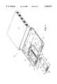
- FIG. 1is an exploded pictorial view of a modular electronic device showing an installed option card piggybacked on a motherboard in accordance with the present invention
- FIG. 2is a side elevation of a righthand card guide in accordance with the present invention.
- FIG. 3is a top view of the righthand card guide illustrated in FIG. 2;
- FIG. 4is a bottom view of the righthand card guide illustrated in FIG. 2;
- FIG. 5is an enlarged cross section taken on the line 55 of FIG. 2 and looking in the direction of the arrows;
- FIG. 6is an enlarged cross section taken on the line 66 of FIG. 2 and looking in the direction of the arrows;
- FIG. 7is a cross section, with parts broken away, taken on the line 77 of FIG. 5 and looking in the direction of the arrows;
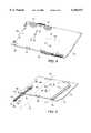
- FIG. 8is a pictorial view of a PCB in accordance with the present invention.
- FIG. 9is an exploded pictorial view, with parts broken away, illustrating the installation of a card guide pair on a PCB in accordance with the present invention.
- FIG. 1depicts modular electronic device 10, which may be a PC, a peripheral device (e.g., a modem), or other modular electronic system.
- Device 10includes motherboard 11, chassis 12, cover 13 and similarly shaped circuit cards 15A and 15B.
- Motherboard 11comprises PCB 18, on which card connectors 14 and other components are mounted.
- the walls of chassis 12have several openings for containing a variety of conventional components, such as cable connectors, switches, display lights, option cards, etc.
- Solid plates(not shown) normally cover any unused openings in chassis 12.
- FIG. 1shows only a limited number of components on motherboard 11. However, like most finished PCB assemblies, motherboard 11 would normally contain a plethora of etched conductors and other components.
- reference charactersappear in FIG. 1 for only significant components and structures of electronic device 10, while other structures are simply shown and not described.
- Electronic device 10further includes expansion slots 22 and 23, which are accessed through openings in the front wall of chassis 12.
- Each of the expansion slots 22 and 23contains a cardguide pair mounted on PCB 18 in alignment with a corresponding connector 14 and an opening in the front wall of chassis 12.
- Each cardguide pairincludes two parallel card guides, namely, lefthand card guide 25 and matching righthand card guide 26.
- Card guides 25 and 26are preferably molded from plastic or other electrically nonconductive material.
- FIGS. 2-7 and 9 and the corresponding description belowdisclose the structural details of card guides 25 and 26.
- FIG. 1further shows circuit cards 15A and 15B each comprising a generally rectangular PCB assembly 21.
- Card connectors 17are located on an edge of PCB assemblies 21.
- An opposite edge of each PCB assembly 21holds an interface device 20 for communicating with a conventional external device (not shown) in a known manner.
- Interface device 20comprises faceplate 31, connector 32 and a pair of panel fasteners 33.
- each PCB assembly 21has parallel mounting edges 29 that are sized to mate with card guides 25 and 26 in a manner to be described below in detail.
- Circuit cards 15A and 15Brepresent examples of common option cards found in many conventional electronic systems. Thus, the usual conductors and other components that populate a PCB of a conventional option card have been omitted here for clarity.
- FIG. 1shows circuit card 15A fully installed in expansion slot 22, while circuit card 15B is shown spaced from and in alignment with the opening of expansion slot 23.
- a userwishes to install a particular option card, say circuit card 15B, in an unused expansion slot, say expansion slot 23, the user first removes any blank plate that may be covering the chassis opening for slot 23. Next, the user inserts card 15B into slot 23 with connector 17 inserted first, as illustrated in FIG. 1.
- a card installershould be capable of manually mounting card guides 25 and 26 on a fully populated motherboard 11 with only moderate effort and no special tools.
- the installation procedureshould be such that the structural and functional integrity of motherboard 11 is not jeopardized.
- mounting structuresare provided that permit guides 25 and 26 to be installed manually, without the use of tools and with no forces being directed transverse to the plane of PCB 18.
- FIGS. 2-7 and 9depict the structural details of card guides 25 and 26, while FIGS. 8 and 9 show details of PCB 18.
- FIGS. 1, 2 and 9lefthand card guide 25 and righthand card guide 26 are mirror images of each other.
- FIGS. 2-7illustrate only the details of righthand card guide 26. Similar details with respect to card guide 25 are shown in FIG. 9.
- card guide 26comprises top member 43, bottom member 44 and longitudinal groove 45.
- Groove 45has a height that is greater than that of edge 29 on PCB 21, as depicted with phantom lines in FIG. 5.
- a pair of spaced, mushroom lugs 40extends from bottom member 44.
- Lugs 40include a relatively narrow neck 41 on which a larger head 42 mounts.
- ramp 48extends from one end of groove 45 to front entrance port 51.
- ramp 49extends from a second end of groove 45 to rear entrance port 52.
- Hook 55mounts on card guide 26 just below ramp 48. Specifically, hook 55, which has a barb 56, resiliently attaches to the bottom surface of card guide 26.
- card guides 25 and 26are mirror images of each other; the essential difference between guides 25 and 26 is that their grooves 45 open in opposite directions. Specifically, groove 45 in righthand card guide 26 opens to the left while groove 45 in lefthand cardguide 25 opens to the right.
- PCB 18comprises a number of apertures that operate with mushroom lugs 40 and hook 55 to fix card guides 25 and 26 on motherboard 11.
- PCB 18includes aligned keyhole apertures 58, which receive mushroom lugs 40, as best seen in FIG. 9.
- Keyhole apertures 58each include a relatively large section and a narrower section. The diameter of the large section is greater than the diameter of head 42 on lug 40. The width of the narrower section of aperture 58 is less than the diameter of head 42 and greater than the thickness of neck 41.
- a front edge of PCB 18includes a set of locking apertures 59. Each locking aperture 59 is sized to mate with barb 56 on hook 55.
- FIG. 9illustrates with dashed lines 61 and 62
- FIG. 9illustrates with dashed lines 61 and 62
- the installerslides the relevant card guide towards the rear until its hook 55 snaps into locking aperture 59.
- necks 41 on mushroom lugs 40will reside in the narrower sections of keyhole apertures 58, while heads 42 and bottom member 44 sit on opposite sides of PCB 18.
- barb 56will project into locking aperture 59.
- mushroom lugs 40, hook 51, and apertures 58 and 59essentially operate to anchor card guides 25 and 26 on PCB 18.
- card guides 25 and 26may be reliably performed on a fully populated PCB assembly, such as a finished motherboard 11, without damaging delicate conductive etchings or other circuit components.
- the only significant installation force required, when installing card guides 25 and 26,is the force required to couple hook 55 with locking aperture 59.
- the magnitude of that forcewhich is primarily a function of the flexibility of hook 51, would normally be quite small.
- the direction of that insertion forcewould lie substantially in the plane of PCB 18. Since card guides 25 and 26 are installed in a motion that is parallel to the surface of PCB 18, any installation forces transmitted to PCB 18 will be in line with the "strong" direction of PCB 18. This will result in only negligible flexure of PCB 18 during cardguide installation. Consequently, a guide installer may manually affix guides 25 and 26 with only moderate hand pressure, thereby eliminating the need for a hammer or other tool as is normally required when installing conventional card guides.
- card guides 25 and 26contain entrance ports, viz., ports 51 and 52, at either end thereof, circuit cards may be inserted into grooves 45 from either the front or rear ends of guides 25 and 26. It is also contemplated that card guides 25 and 26 may be constructed with two, back-to-back grooves rather than the single groove, i.e., groove 57, as depicted in the drawings. With a two-groove configuration, card guides could be used as righthand or lefthand guides. Additionally, a single card guide with two grooves may be shared by adjacent expansion ports.
- various other modifications and variationsare contemplated and may obviously be resorted to in light of the present disclosure. It is to be understood, therefore, that within the scope of the appended claims, the invention may be practiced otherwise than as specifically described.
Landscapes
- Engineering & Computer Science (AREA)
- Computer Hardware Design (AREA)
- General Engineering & Computer Science (AREA)
- Theoretical Computer Science (AREA)
- Microelectronics & Electronic Packaging (AREA)
- Power Engineering (AREA)
- Human Computer Interaction (AREA)
- Physics & Mathematics (AREA)
- General Physics & Mathematics (AREA)
- Mounting Of Printed Circuit Boards And The Like (AREA)
Abstract
Description
Claims (23)
Priority Applications (1)
| Application Number | Priority Date | Filing Date | Title |
|---|---|---|---|
| US09/003,627US6166917A (en) | 1998-01-07 | 1998-01-07 | Techniques of assembling modular electronic equipment |
Applications Claiming Priority (1)
| Application Number | Priority Date | Filing Date | Title |
|---|---|---|---|
| US09/003,627US6166917A (en) | 1998-01-07 | 1998-01-07 | Techniques of assembling modular electronic equipment |
Publications (1)
| Publication Number | Publication Date |
|---|---|
| US6166917Atrue US6166917A (en) | 2000-12-26 |
Family
ID=21706777
Family Applications (1)
| Application Number | Title | Priority Date | Filing Date |
|---|---|---|---|
| US09/003,627Expired - LifetimeUS6166917A (en) | 1998-01-07 | 1998-01-07 | Techniques of assembling modular electronic equipment |
Country Status (1)
| Country | Link |
|---|---|
| US (1) | US6166917A (en) |
Cited By (56)
| Publication number | Priority date | Publication date | Assignee | Title |
|---|---|---|---|---|
| US6385051B1 (en)* | 2000-03-13 | 2002-05-07 | Compaq Computer Corporation | Circuit board mounting apparatus and associated methods |
| US6418028B2 (en)* | 2000-02-22 | 2002-07-09 | Nec Corporation | Reinforcing structure for a printed circuit board |
| US20030076658A1 (en)* | 2001-10-22 | 2003-04-24 | Aronson Lewis B. | Multiple width transceiver host board system |
| US6646890B1 (en)* | 2002-09-04 | 2003-11-11 | Lucent Technologies Inc. | Mounting of mezzanine circuit boards to a base board |
| US6647618B2 (en)* | 1999-07-22 | 2003-11-18 | Hewlett-Packard Development Company, Lp. | Method of assembling a circuit board into a housing |
| US20040031767A1 (en)* | 2002-08-13 | 2004-02-19 | Ice Donald A. | Adapter element for card cage system |
| US20040037054A1 (en)* | 2002-08-13 | 2004-02-26 | Ice Donald A. | Card cage system |
| US20040047119A1 (en)* | 2001-08-22 | 2004-03-11 | Michael Wortman | Housing assembly having simplified circuit board assembly, retention, and electrical connection features |
| US20040201956A1 (en)* | 2003-04-09 | 2004-10-14 | Conway Craig M. | PXI chassis with backwards compatibility for existing PXI devices |
| US20040252469A1 (en)* | 2003-06-10 | 2004-12-16 | Campbell Robert G. | Card guide for expansion circuit card |
| US20050018389A1 (en)* | 2003-07-24 | 2005-01-27 | International Business Machines Corporation | Alignment docking system |
| US6850409B1 (en)* | 2003-01-25 | 2005-02-01 | Foundry Networks, Inc. | Shim assembly for hardware module |
| US20050106936A1 (en)* | 2003-11-18 | 2005-05-19 | Hsuan-Tsung Chen | Mounting apparatus for circuit board |
| US20050135069A1 (en)* | 2003-12-22 | 2005-06-23 | Emc Corporation | Midplane-less data storage enclosure |
| US20060023429A1 (en)* | 2000-10-17 | 2006-02-02 | Spx Corporation | Plug-in module for portable computing device |
| US20060044775A1 (en)* | 2004-08-31 | 2006-03-02 | Kabushiki Kaisha Toshiba | Case for electronic equipment and communication device |
| US7050306B1 (en)* | 2000-10-17 | 2006-05-23 | Spx Corporation | Plug-in module for portable computing device |
| US20060185880A1 (en)* | 2005-02-24 | 2006-08-24 | Dong-Hyok Shin | Chassis base assembly and plasma display panel assembly including the same |
| US7099160B1 (en)* | 2002-10-31 | 2006-08-29 | Finisar Corporation | Card guide systems and devices |
| EP1793305A1 (en)* | 2005-12-05 | 2007-06-06 | General Electric Company | Method and system for mounting circuit boards to a base board |
| US20080037218A1 (en)* | 2006-03-24 | 2008-02-14 | Sharma Viswa M | Modular chassis providing scalable mechanical, electrical and environmental functionality for MicroTCA and advanced TCA boards |
| US7349226B2 (en) | 2002-08-13 | 2008-03-25 | Finisar Corporation | Functional module with card guide engagement feature |
| US20080158837A1 (en)* | 2006-12-28 | 2008-07-03 | General Electric Company | Apparatus and method for holding a card |
| US20080180920A1 (en)* | 2007-01-30 | 2008-07-31 | Yin-Lung Chang | Pluggable guiding apparatus |
| US20080298014A1 (en)* | 2007-05-29 | 2008-12-04 | Michael John Franco | Modular electronic enclosure |
| US20080298028A1 (en)* | 2007-05-31 | 2008-12-04 | Matthew Travers | Amc carrier faceplates |
| US20090052139A1 (en)* | 2007-08-23 | 2009-02-26 | Kuping Lai | Heat-Dissipation Apparatus For Communication Device With Card Slot |
| US20100046181A1 (en)* | 2008-08-25 | 2010-02-25 | Gridpoint Systems, Inc. | Removable card guides for horizontal line cards |
| US20100134989A1 (en)* | 2008-11-30 | 2010-06-03 | Dell Products L.P. | Expansion Card Retention Apparatus, Systems and Methods |
| US20100149759A1 (en)* | 2008-12-12 | 2010-06-17 | Finisar Corporation | Thumbscrew for pluggable modules |
| US7827442B2 (en) | 2006-01-23 | 2010-11-02 | Slt Logic Llc | Shelf management controller with hardware/software implemented dual redundant configuration |
| DE102009054422B3 (en)* | 2009-11-24 | 2010-11-11 | Sinitec Vertriebsgesellschaft Mbh | Arrangement for fastening computer component in computer arranged in separate housing, has base plate which is formed as part of computer housing |
| CN101893920A (en)* | 2009-05-22 | 2010-11-24 | 鸿富锦精密工业(深圳)有限公司 | Motherboard Fixture |
| WO2010138824A3 (en)* | 2009-05-28 | 2011-02-24 | Microblade, Llc | Microtca device |
| US20110057894A1 (en)* | 2009-09-07 | 2011-03-10 | Sony Corporation | Information processing device |
| US20110194245A1 (en)* | 2010-02-06 | 2011-08-11 | Inventec Corporation | Server |
| US20120008292A1 (en)* | 2010-07-08 | 2012-01-12 | Tyco Electronics Corporation | Card module and module connector assembly |
| BE1019310A4 (en)* | 2010-04-21 | 2012-05-08 | Ydetec Electronics Sprl | BOX FOR INCORPORATING AN ELECTRONIC CARD "EUROPE" EQUIPPED WITH ITS CONNECTOR DIN 41612. |
| US20120113613A1 (en)* | 2010-02-12 | 2012-05-10 | Chad Anderson | Communications bladed panel systems |
| US8189599B2 (en) | 2005-08-23 | 2012-05-29 | Rpx Corporation | Omni-protocol engine for reconfigurable bit-stream processing in high-speed networks |
| US20120281372A1 (en)* | 2011-05-06 | 2012-11-08 | Funai Electric Co., Ltd. | Board attachment structure and electric device |
| US20130223026A1 (en)* | 2012-02-29 | 2013-08-29 | Hon Hai Precision Industry Co., Ltd. | Electronic device with distribution board |
| US8755192B1 (en)* | 2010-03-31 | 2014-06-17 | Amazon Technologies, Inc. | Rack-mounted computer system with shock-absorbing chassis |
| US20150009639A1 (en)* | 2013-07-02 | 2015-01-08 | Kimon Papakos | System and method for housing circuit boards of different physical dimensions |
| US9426903B1 (en) | 2008-06-27 | 2016-08-23 | Amazon Technologies, Inc. | Cooling air stack for computer equipment |
| US9459658B1 (en)* | 2015-07-02 | 2016-10-04 | Quanta Computer Inc. | Modular electronic device |
| US20160324028A1 (en)* | 2013-12-11 | 2016-11-03 | Enensys Technologies | Housing for at least one electronic card |
| US20160353589A1 (en)* | 2015-05-28 | 2016-12-01 | Azbil Corporation | Lock structure of circuit board unit |
| US9622387B1 (en) | 2010-03-31 | 2017-04-11 | Amazon Technologies, Inc. | Rack-mounted air directing device with scoop |
| US9894808B2 (en) | 2010-03-31 | 2018-02-13 | Amazon Technologies, Inc. | Compressed air cooling system for data center |
| US9894809B1 (en) | 2013-02-28 | 2018-02-13 | Amazon Technologies, Inc. | System for supplying cooling air from sub-floor space |
| US10082857B1 (en) | 2012-08-07 | 2018-09-25 | Amazon Technologies, Inc. | Cooling electrical systems based on power measurements |
| US10492331B1 (en) | 2010-09-29 | 2019-11-26 | Amazon Technologies, Inc. | System and method for cooling power distribution units |
| US20200068712A1 (en)* | 2018-08-22 | 2020-02-27 | Quanta Computer Inc. | Motherboard with daughter input/output board |
| WO2021185930A1 (en)* | 2020-03-19 | 2021-09-23 | Fujitsu Client Computing Limited | Computer and method for fixing an expansion card in a computer |
| US20240070429A1 (en)* | 2022-08-29 | 2024-02-29 | RADX Technologies, Inc. | Carrier card with reduced width |
Citations (17)
| Publication number | Priority date | Publication date | Assignee | Title |
|---|---|---|---|---|
| US3723823A (en)* | 1971-11-30 | 1973-03-27 | Gen Electric | Printed circuit board guide |
| US3736472A (en)* | 1971-10-04 | 1973-05-29 | E Muldoon | Circuit board guide and support apparatus having improved fastenings for rigid assembly |
| US3878438A (en)* | 1973-09-28 | 1975-04-15 | William Jacobs A K A Calmark | Printed circuit card guide |
| US3899721A (en)* | 1974-03-20 | 1975-08-12 | Bell Telephone Labor Inc | Printed circuit card guide |
| US4534472A (en)* | 1982-09-30 | 1985-08-13 | Contraves Ag | Guide rail for electronic module supports |
| US4924354A (en)* | 1983-09-22 | 1990-05-08 | Schroff Gesellschaft Mit Beschrankter Haftung | Guide rail comprising attachment means for a plug board |
| US5406455A (en)* | 1993-08-16 | 1995-04-11 | Nec America, Inc. | Snap-in card guide |
| US5467254A (en)* | 1993-11-04 | 1995-11-14 | Synoptics Communications, Inc. | Supportive guide for circuit-card grounding including tracks having staggered protrusions at the proximal end of the tracks |
| US5530624A (en)* | 1995-01-03 | 1996-06-25 | Xerox Corporation | Card connector interface guide and printed wiring board assembly slide |
| US5533631A (en)* | 1994-10-12 | 1996-07-09 | Unitrack Industries, Inc. | Composite printed circuit card guide and holding device |
| US5555158A (en)* | 1995-01-30 | 1996-09-10 | Intel Corporation | Motherboard for personal computer standard desktop chassis |
| US5642264A (en)* | 1991-04-01 | 1997-06-24 | E-Systems, Inc. | Apparatus for supporting circuit cards in slot locations |
| US5657204A (en)* | 1996-09-10 | 1997-08-12 | Paradyne Corporation | PC add-on board installation apparatus for industrial applications |
| US5661640A (en)* | 1996-01-05 | 1997-08-26 | Dell Usa, L.P. | Computer chassis having a size-adjustable, TEM-shielded circuit board support plate structure therein |
| US5680296A (en)* | 1995-11-07 | 1997-10-21 | Sun Microsystems, Inc. | Card guide with groove having a base portion and ramped portion which restrains an electronic card |
| US5738226A (en)* | 1996-10-31 | 1998-04-14 | Hewlett-Packard Company | Guide piece and method for mounting to a chassis in multiple orientations |
| US5805429A (en)* | 1994-06-10 | 1998-09-08 | Telefonaktiebolaget Lm Ericsson | Rail assembly |
- 1998
- 1998-01-07USUS09/003,627patent/US6166917A/ennot_activeExpired - Lifetime
Patent Citations (17)
| Publication number | Priority date | Publication date | Assignee | Title |
|---|---|---|---|---|
| US3736472A (en)* | 1971-10-04 | 1973-05-29 | E Muldoon | Circuit board guide and support apparatus having improved fastenings for rigid assembly |
| US3723823A (en)* | 1971-11-30 | 1973-03-27 | Gen Electric | Printed circuit board guide |
| US3878438A (en)* | 1973-09-28 | 1975-04-15 | William Jacobs A K A Calmark | Printed circuit card guide |
| US3899721A (en)* | 1974-03-20 | 1975-08-12 | Bell Telephone Labor Inc | Printed circuit card guide |
| US4534472A (en)* | 1982-09-30 | 1985-08-13 | Contraves Ag | Guide rail for electronic module supports |
| US4924354A (en)* | 1983-09-22 | 1990-05-08 | Schroff Gesellschaft Mit Beschrankter Haftung | Guide rail comprising attachment means for a plug board |
| US5642264A (en)* | 1991-04-01 | 1997-06-24 | E-Systems, Inc. | Apparatus for supporting circuit cards in slot locations |
| US5406455A (en)* | 1993-08-16 | 1995-04-11 | Nec America, Inc. | Snap-in card guide |
| US5467254A (en)* | 1993-11-04 | 1995-11-14 | Synoptics Communications, Inc. | Supportive guide for circuit-card grounding including tracks having staggered protrusions at the proximal end of the tracks |
| US5805429A (en)* | 1994-06-10 | 1998-09-08 | Telefonaktiebolaget Lm Ericsson | Rail assembly |
| US5533631A (en)* | 1994-10-12 | 1996-07-09 | Unitrack Industries, Inc. | Composite printed circuit card guide and holding device |
| US5530624A (en)* | 1995-01-03 | 1996-06-25 | Xerox Corporation | Card connector interface guide and printed wiring board assembly slide |
| US5555158A (en)* | 1995-01-30 | 1996-09-10 | Intel Corporation | Motherboard for personal computer standard desktop chassis |
| US5680296A (en)* | 1995-11-07 | 1997-10-21 | Sun Microsystems, Inc. | Card guide with groove having a base portion and ramped portion which restrains an electronic card |
| US5661640A (en)* | 1996-01-05 | 1997-08-26 | Dell Usa, L.P. | Computer chassis having a size-adjustable, TEM-shielded circuit board support plate structure therein |
| US5657204A (en)* | 1996-09-10 | 1997-08-12 | Paradyne Corporation | PC add-on board installation apparatus for industrial applications |
| US5738226A (en)* | 1996-10-31 | 1998-04-14 | Hewlett-Packard Company | Guide piece and method for mounting to a chassis in multiple orientations |
Non-Patent Citations (1)
| Title |
|---|
| Bivar, 1995/96 Thirtieth Anniversary Catalog, pp. 10 and 16, 1995.* |
Cited By (99)
| Publication number | Priority date | Publication date | Assignee | Title |
|---|---|---|---|---|
| US6647618B2 (en)* | 1999-07-22 | 2003-11-18 | Hewlett-Packard Development Company, Lp. | Method of assembling a circuit board into a housing |
| US6418028B2 (en)* | 2000-02-22 | 2002-07-09 | Nec Corporation | Reinforcing structure for a printed circuit board |
| US6934162B2 (en) | 2000-03-13 | 2005-08-23 | Hewlett-Packard Development Company, L.P. | Circuit board mounting methods |
| US6385051B1 (en)* | 2000-03-13 | 2002-05-07 | Compaq Computer Corporation | Circuit board mounting apparatus and associated methods |
| US20060023429A1 (en)* | 2000-10-17 | 2006-02-02 | Spx Corporation | Plug-in module for portable computing device |
| US7324346B2 (en) | 2000-10-17 | 2008-01-29 | Spx Corporation | Plug-in module for portable computing device |
| US7050306B1 (en)* | 2000-10-17 | 2006-05-23 | Spx Corporation | Plug-in module for portable computing device |
| US6940726B2 (en)* | 2001-08-22 | 2005-09-06 | Hewlett-Packard Development Company, L.P. | Housing assembly having simplified circuit board assembly, retention, and electrical connection features |
| US20040047119A1 (en)* | 2001-08-22 | 2004-03-11 | Michael Wortman | Housing assembly having simplified circuit board assembly, retention, and electrical connection features |
| US7177157B2 (en)* | 2001-10-22 | 2007-02-13 | Finisar Corporation | Multiple width transceiver host board system |
| US20030076658A1 (en)* | 2001-10-22 | 2003-04-24 | Aronson Lewis B. | Multiple width transceiver host board system |
| US20040037054A1 (en)* | 2002-08-13 | 2004-02-26 | Ice Donald A. | Card cage system |
| US7210586B2 (en) | 2002-08-13 | 2007-05-01 | Finisar Corporation | Adapter element for card cage system |
| US7167380B2 (en) | 2002-08-13 | 2007-01-23 | Finisar Corporation | Card cage system |
| US7349226B2 (en) | 2002-08-13 | 2008-03-25 | Finisar Corporation | Functional module with card guide engagement feature |
| US20040031767A1 (en)* | 2002-08-13 | 2004-02-19 | Ice Donald A. | Adapter element for card cage system |
| US6646890B1 (en)* | 2002-09-04 | 2003-11-11 | Lucent Technologies Inc. | Mounting of mezzanine circuit boards to a base board |
| US7099160B1 (en)* | 2002-10-31 | 2006-08-29 | Finisar Corporation | Card guide systems and devices |
| US6850409B1 (en)* | 2003-01-25 | 2005-02-01 | Foundry Networks, Inc. | Shim assembly for hardware module |
| US20040201956A1 (en)* | 2003-04-09 | 2004-10-14 | Conway Craig M. | PXI chassis with backwards compatibility for existing PXI devices |
| US7149093B2 (en)* | 2003-04-09 | 2006-12-12 | National Instruments Corporation | PXI chassis with backwards compatibility for existing PXI devices |
| US7187555B2 (en)* | 2003-06-10 | 2007-03-06 | Hewlett-Packard Development Company, L.P. | Card guide for expansion circuit card |
| US20040252469A1 (en)* | 2003-06-10 | 2004-12-16 | Campbell Robert G. | Card guide for expansion circuit card |
| US6950301B2 (en) | 2003-07-24 | 2005-09-27 | International Business Machines Corporation | Alignment docking system |
| US20050018389A1 (en)* | 2003-07-24 | 2005-01-27 | International Business Machines Corporation | Alignment docking system |
| US20050106936A1 (en)* | 2003-11-18 | 2005-05-19 | Hsuan-Tsung Chen | Mounting apparatus for circuit board |
| US6964581B2 (en)* | 2003-11-18 | 2005-11-15 | Hon Hai Precision Ind. Co., Ltd | Mounting apparatus for circuit board |
| US20050135069A1 (en)* | 2003-12-22 | 2005-06-23 | Emc Corporation | Midplane-less data storage enclosure |
| US7145776B2 (en)* | 2003-12-22 | 2006-12-05 | Emc Corporation | Midplane-less data storage enclosure |
| US7489522B2 (en)* | 2004-08-31 | 2009-02-10 | Kabushiki Kaisha Toshiba | Case for electronic equipment and communication device |
| US20060044775A1 (en)* | 2004-08-31 | 2006-03-02 | Kabushiki Kaisha Toshiba | Case for electronic equipment and communication device |
| US20060185880A1 (en)* | 2005-02-24 | 2006-08-24 | Dong-Hyok Shin | Chassis base assembly and plasma display panel assembly including the same |
| US8189599B2 (en) | 2005-08-23 | 2012-05-29 | Rpx Corporation | Omni-protocol engine for reconfigurable bit-stream processing in high-speed networks |
| EP1793305A1 (en)* | 2005-12-05 | 2007-06-06 | General Electric Company | Method and system for mounting circuit boards to a base board |
| US20070127225A1 (en)* | 2005-12-05 | 2007-06-07 | Slaton David S | Method and system for mounting circuit boards |
| US7827442B2 (en) | 2006-01-23 | 2010-11-02 | Slt Logic Llc | Shelf management controller with hardware/software implemented dual redundant configuration |
| US20080037218A1 (en)* | 2006-03-24 | 2008-02-14 | Sharma Viswa M | Modular chassis providing scalable mechanical, electrical and environmental functionality for MicroTCA and advanced TCA boards |
| US7821790B2 (en)* | 2006-03-24 | 2010-10-26 | Slt Logic, Llc | Modular chassis providing scalable mechanical, electrical and environmental functionality for MicroTCA and Advanced TCA boards |
| US7573719B2 (en)* | 2006-12-28 | 2009-08-11 | General Electric Company | Apparatus and method for holding a card |
| US20080158837A1 (en)* | 2006-12-28 | 2008-07-03 | General Electric Company | Apparatus and method for holding a card |
| US20080180920A1 (en)* | 2007-01-30 | 2008-07-31 | Yin-Lung Chang | Pluggable guiding apparatus |
| US7843704B2 (en)* | 2007-01-30 | 2010-11-30 | Accton Technology Corporation | Pluggable guiding apparatus |
| US20080298014A1 (en)* | 2007-05-29 | 2008-12-04 | Michael John Franco | Modular electronic enclosure |
| US8164906B2 (en) | 2007-05-29 | 2012-04-24 | Michael John Franco | Modular electronic enclosure |
| US20080298028A1 (en)* | 2007-05-31 | 2008-12-04 | Matthew Travers | Amc carrier faceplates |
| US20090052139A1 (en)* | 2007-08-23 | 2009-02-26 | Kuping Lai | Heat-Dissipation Apparatus For Communication Device With Card Slot |
| US9918412B2 (en) | 2008-06-27 | 2018-03-13 | Amazon Technologies, Inc. | Cooling air stack for computer equipment |
| US9426903B1 (en) | 2008-06-27 | 2016-08-23 | Amazon Technologies, Inc. | Cooling air stack for computer equipment |
| US20100046181A1 (en)* | 2008-08-25 | 2010-02-25 | Gridpoint Systems, Inc. | Removable card guides for horizontal line cards |
| US7920387B2 (en)* | 2008-08-25 | 2011-04-05 | Ciena Corporation | Removable card guides for horizontal line cards |
| US8264830B2 (en)* | 2008-11-30 | 2012-09-11 | Dell Products L.P. | Expansion card retention apparatus, systems and methods |
| US20100134989A1 (en)* | 2008-11-30 | 2010-06-03 | Dell Products L.P. | Expansion Card Retention Apparatus, Systems and Methods |
| US8427837B2 (en) | 2008-12-12 | 2013-04-23 | Finisar Corporation | Thumbscrew for pluggable modules |
| US20100149759A1 (en)* | 2008-12-12 | 2010-06-17 | Finisar Corporation | Thumbscrew for pluggable modules |
| US8199494B2 (en)* | 2008-12-12 | 2012-06-12 | Finisar Corporation, Inc. | Thumbscrew for pluggable modules |
| CN101893920A (en)* | 2009-05-22 | 2010-11-24 | 鸿富锦精密工业(深圳)有限公司 | Motherboard Fixture |
| US20100296241A1 (en)* | 2009-05-22 | 2010-11-25 | Hong Fu Jin Precision Industry (Shenzhen) Co., Ltd | Computer chassis for mounting motherboard therein |
| CN101893920B (en)* | 2009-05-22 | 2014-03-26 | 鸿富锦精密工业(深圳)有限公司 | Main board fixing device |
| US8248817B2 (en)* | 2009-05-22 | 2012-08-21 | Hong Fu Jin Precision Industry (Shenzhen) Co., Ltd. | Computer chassis for mounting motherboard therein |
| WO2010138824A3 (en)* | 2009-05-28 | 2011-02-24 | Microblade, Llc | Microtca device |
| US8526175B2 (en)* | 2009-09-07 | 2013-09-03 | Sony Corporation | Information processing device |
| US20110057894A1 (en)* | 2009-09-07 | 2011-03-10 | Sony Corporation | Information processing device |
| DE102009054422B3 (en)* | 2009-11-24 | 2010-11-11 | Sinitec Vertriebsgesellschaft Mbh | Arrangement for fastening computer component in computer arranged in separate housing, has base plate which is formed as part of computer housing |
| US8134843B2 (en)* | 2010-02-06 | 2012-03-13 | Inventec Corporation | Server |
| US20110194245A1 (en)* | 2010-02-06 | 2011-08-11 | Inventec Corporation | Server |
| US8923013B2 (en) | 2010-02-12 | 2014-12-30 | Adc Telecommunications, Inc. | Communications bladed panel systems |
| US9532481B2 (en) | 2010-02-12 | 2016-12-27 | Commscope Technologies Llc | Communications bladed panel systems |
| US20120113613A1 (en)* | 2010-02-12 | 2012-05-10 | Chad Anderson | Communications bladed panel systems |
| US10123444B2 (en) | 2010-02-12 | 2018-11-06 | Commscope Technologies Llc | Communications bladed panel systems |
| US9532482B2 (en) | 2010-02-12 | 2016-12-27 | Commscope Technologies Llc | Communications bladed panel systems |
| US9549484B2 (en) | 2010-02-12 | 2017-01-17 | Commscope Technologies Llc | Communications bladed panel systems |
| US9265172B2 (en) | 2010-02-12 | 2016-02-16 | Commscope Technologies Llc | Communications bladed panel systems |
| US8934253B2 (en) | 2010-02-12 | 2015-01-13 | Adc Telecommunications, Inc. | Communications bladed panel systems |
| US8934252B2 (en) | 2010-02-12 | 2015-01-13 | Adc Telecommunications, Inc. | Communications bladed panel systems |
| US9020319B2 (en)* | 2010-02-12 | 2015-04-28 | Adc Telecommunications, Inc. | Communications bladed panel systems |
| US9198320B2 (en) | 2010-02-12 | 2015-11-24 | Tyco Electronics Services Gmbh | Communications bladed panel systems |
| US9213363B2 (en) | 2010-02-12 | 2015-12-15 | Tyco Electronics Services Gmbh | Communications bladed panel systems |
| US9223105B2 (en) | 2010-02-12 | 2015-12-29 | Commscope Technologies Llc | Communications bladed panel systems |
| US9622387B1 (en) | 2010-03-31 | 2017-04-11 | Amazon Technologies, Inc. | Rack-mounted air directing device with scoop |
| US9894808B2 (en) | 2010-03-31 | 2018-02-13 | Amazon Technologies, Inc. | Compressed air cooling system for data center |
| US8755192B1 (en)* | 2010-03-31 | 2014-06-17 | Amazon Technologies, Inc. | Rack-mounted computer system with shock-absorbing chassis |
| BE1019310A4 (en)* | 2010-04-21 | 2012-05-08 | Ydetec Electronics Sprl | BOX FOR INCORPORATING AN ELECTRONIC CARD "EUROPE" EQUIPPED WITH ITS CONNECTOR DIN 41612. |
| US8325488B2 (en)* | 2010-07-08 | 2012-12-04 | Tyco Electronics Corporation | Card module and module connector assembly |
| US20120008292A1 (en)* | 2010-07-08 | 2012-01-12 | Tyco Electronics Corporation | Card module and module connector assembly |
| US10492331B1 (en) | 2010-09-29 | 2019-11-26 | Amazon Technologies, Inc. | System and method for cooling power distribution units |
| US20120281372A1 (en)* | 2011-05-06 | 2012-11-08 | Funai Electric Co., Ltd. | Board attachment structure and electric device |
| US20130223026A1 (en)* | 2012-02-29 | 2013-08-29 | Hon Hai Precision Industry Co., Ltd. | Electronic device with distribution board |
| US10082857B1 (en) | 2012-08-07 | 2018-09-25 | Amazon Technologies, Inc. | Cooling electrical systems based on power measurements |
| US9894809B1 (en) | 2013-02-28 | 2018-02-13 | Amazon Technologies, Inc. | System for supplying cooling air from sub-floor space |
| US20150009639A1 (en)* | 2013-07-02 | 2015-01-08 | Kimon Papakos | System and method for housing circuit boards of different physical dimensions |
| US9743548B2 (en)* | 2013-12-11 | 2017-08-22 | Enensys Technologies | Housing for at least one electronic card |
| US20160324028A1 (en)* | 2013-12-11 | 2016-11-03 | Enensys Technologies | Housing for at least one electronic card |
| US20160353589A1 (en)* | 2015-05-28 | 2016-12-01 | Azbil Corporation | Lock structure of circuit board unit |
| US9668365B2 (en)* | 2015-05-28 | 2017-05-30 | Azbil Corporation | Lock structure of circuit board unit |
| US9459658B1 (en)* | 2015-07-02 | 2016-10-04 | Quanta Computer Inc. | Modular electronic device |
| US20200068712A1 (en)* | 2018-08-22 | 2020-02-27 | Quanta Computer Inc. | Motherboard with daughter input/output board |
| US10624211B2 (en)* | 2018-08-22 | 2020-04-14 | Quanta Computer Inc. | Motherboard with daughter input/output board |
| WO2021185930A1 (en)* | 2020-03-19 | 2021-09-23 | Fujitsu Client Computing Limited | Computer and method for fixing an expansion card in a computer |
| US20240070429A1 (en)* | 2022-08-29 | 2024-02-29 | RADX Technologies, Inc. | Carrier card with reduced width |
Similar Documents
| Publication | Publication Date | Title |
|---|---|---|
| US6166917A (en) | Techniques of assembling modular electronic equipment | |
| EP1793305B1 (en) | Method and system for mounting circuit boards to a base board | |
| US7742291B2 (en) | Computer enclosure adapted for mounting different types of transfer cards | |
| US7626830B2 (en) | Bracket assembly for expansion cards | |
| EP1072178B1 (en) | Circuit card insertion and removal system | |
| US5973926A (en) | Method and apparatus for attaching circuit board to chassis and forming solid ground connection using a single screw | |
| US5757618A (en) | Expansion board mounting structure for computers | |
| US6535394B1 (en) | Printed circuit board attachment structure | |
| US4519667A (en) | Electrical connector | |
| US20040074854A1 (en) | Expansion card mounting apparatus | |
| US6442038B1 (en) | Expansion card hold down assembly | |
| US7326067B2 (en) | Method and apparatus for minimizing the installation height of electrical components | |
| US20130021743A1 (en) | Expansion card mounting assembly | |
| US7256985B1 (en) | Mounting system for electronic components | |
| US6320752B1 (en) | Fixing apparatus for a mounting type card member | |
| US6094358A (en) | Card stiffener optimized for connector engagement | |
| US6247767B1 (en) | Computer enclosure for exclusively mounting two different sized switching power supplies | |
| US5812377A (en) | Universal card cage assembly | |
| US6688913B2 (en) | Connector assembly structure | |
| US8254130B2 (en) | Computer system | |
| US7589960B2 (en) | Disk drive assembly | |
| US20060291181A1 (en) | Bracket for expansion card slot | |
| US6216339B1 (en) | Tool-actuated ejector mechanism for extracting electronic modular components | |
| US6538900B2 (en) | Computer enclosure with holder bracket | |
| US7252544B2 (en) | Connector having a U-shaped fixing member with screw holes |
Legal Events
| Date | Code | Title | Description |
|---|---|---|---|
| AS | Assignment | Owner name:3COM CORPORATION, CALIFORNIA Free format text:ASSIGNMENT OF ASSIGNORS INTEREST;ASSIGNOR:ANDERSON, SCOTT;REEL/FRAME:008958/0203 Effective date:19980105 | |
| STCF | Information on status: patent grant | Free format text:PATENTED CASE | |
| FPAY | Fee payment | Year of fee payment:4 | |
| FEPP | Fee payment procedure | Free format text:PAYOR NUMBER ASSIGNED (ORIGINAL EVENT CODE: ASPN); ENTITY STATUS OF PATENT OWNER: LARGE ENTITY | |
| FPAY | Fee payment | Year of fee payment:8 | |
| AS | Assignment | Owner name:HEWLETT-PACKARD COMPANY, CALIFORNIA Free format text:MERGER;ASSIGNOR:3COM CORPORATION;REEL/FRAME:024630/0820 Effective date:20100428 | |
| AS | Assignment | Owner name:HEWLETT-PACKARD COMPANY, CALIFORNIA Free format text:CORRECTIVE ASSIGNMENT TO CORRECT THE SEE ATTACHED;ASSIGNOR:3COM CORPORATION;REEL/FRAME:025039/0844 Effective date:20100428 | |
| AS | Assignment | Owner name:HEWLETT-PACKARD DEVELOPMENT COMPANY, L.P., TEXAS Free format text:ASSIGNMENT OF ASSIGNORS INTEREST;ASSIGNOR:HEWLETT-PACKARD COMPANY;REEL/FRAME:027329/0044 Effective date:20030131 | |
| AS | Assignment | Owner name:HEWLETT-PACKARD DEVELOPMENT COMPANY, L.P., TEXAS Free format text:CORRECTIVE ASSIGNMENT PREVIUOSLY RECORDED ON REEL 027329 FRAME 0001 AND 0044;ASSIGNOR:HEWLETT-PACKARD COMPANY;REEL/FRAME:028911/0846 Effective date:20111010 | |
| FPAY | Fee payment | Year of fee payment:12 | |
| AS | Assignment | Owner name:HEWLETT PACKARD ENTERPRISE DEVELOPMENT LP, TEXAS Free format text:ASSIGNMENT OF ASSIGNORS INTEREST;ASSIGNOR:HEWLETT-PACKARD DEVELOPMENT COMPANY, L.P.;REEL/FRAME:037079/0001 Effective date:20151027 |