US6166744A - System for combining virtual images with real-world scenes - Google Patents
System for combining virtual images with real-world scenesDownload PDFInfo
- Publication number
- US6166744A US6166744AUS09/153,503US15350398AUS6166744AUS 6166744 AUS6166744 AUS 6166744AUS 15350398 AUS15350398 AUS 15350398AUS 6166744 AUS6166744 AUS 6166744A
- Authority
- US
- United States
- Prior art keywords
- virtual
- field
- objects
- real
- image
- Prior art date
- Legal status (The legal status is an assumption and is not a legal conclusion. Google has not performed a legal analysis and makes no representation as to the accuracy of the status listed.)
- Expired - Lifetime
Links
Images


Classifications
- G—PHYSICS
- G06—COMPUTING OR CALCULATING; COUNTING
- G06T—IMAGE DATA PROCESSING OR GENERATION, IN GENERAL
- G06T17/00—Three dimensional [3D] modelling, e.g. data description of 3D objects
Definitions
- the present inventionrelates generally to the field of virtual reality simulation, and more particularly to systems for combining virtual images with real-world scenes.
- Virtual reality systemshave gained wide acceptance in recent years for training and simulations in a number of fields, including aircraft simulators, virtual reality games, surgical training, military training and motion picture and video special effects.
- Conventional virtual reality systemsgenerate a field of view for the user that is either completely computer-generated, or may include real-world scenery as background.
- Some virtual reality systemsuse portions of real-world images (e.g., a particular object, pattern, or texture) that can be incorporated into a computer-generated environment.
- conventional virtual reality systemsdo not typically incorporate virtual images into real-world scenes due to the difficulties of integrating a virtual image into a real-world scene in a realistic manner.
- the virtual imagecan mask portions of the real-world scene, and objects in the real-world scene can mask portions of the virtual image depending on their relative locations and sizes.
- the cost of instrumentation for a large number of vehiclesis also substantial.
- the present inventioncan be used in these war games to generate virtual tanks that appear to move about the terrain. This can completely eliminate the need, for example, for live tanks representing the enemy force in a war gaming exercise. Virtual vehicles and real vehicles can appear in the same scene.
- the present inventioncan also be used to generate virtual "hits" and explosions during an exercise.
- the present inventionalso has application in the field of aircraft simulation.
- Virtual aircraft or virtual flying conditionscan be combined with real-world scenes during an actual flight or a simulated flight.
- Another possible field of useis in games, such as laser tag, so that virtual players, objects, and special effects can be combined with real players and real objects in the playing field.
- the present inventionhas application in the area of entertainment in the high-speed generation of special effects and three-dimensional displays.
- Special effects in the motion picture and video industriesintegrate real-world scenes and computer graphics, that is, virtual images.
- the inventionpermits real-time generation of special effects in video film and motion picture production.
- various three-dimensional motion picture and video systemsthat can replay, with the aid of special display goggles, recorded three-dimensional scenes.
- the present inventioncan be used with electronic display goggles to greatly extend this entertainment medium by injecting, in real time, three-dimensional virtual elements into the view of the real world.
- the method of the present inventioncan be also used to create virtual elements in theme parks and other entertainment-oriented environments.
- the virtual elements injected into real-world environments in entertainment applicationsmay be representations of persons, animals, natural phenomena, cartoon characters, and other real or imaginary visual elements.
- the present systemenables computer-generated virtual images to be combined with images of the real world.
- a range scannerdetermines the shape and distance of real-world objects within a field of regard of interest to the observer.
- Virtual masking objectswhich are simplified computer models of real-world objects, are derived from the range data.
- a computersimulates virtual entities and combines these virtual images with the virtual masking objects to create masked virtual images.
- the masked virtual imagesshow the portions of virtual entities that would be visible if the virtual entities actually existed in the real world.
- the masked virtual images and the real-world sceneare combined and displayed in such a manner that the virtual images appear to be obscured, when appropriate for their simulated location relative to real-world objects.
- This inventionprovides a system for combining virtual images with images of the real world.
- a range scannerdetermines the shape and distance of real-world objects within a field of regard of interest to the observer using the apparatus.
- Virtual masking objectswhich are simplified computer models of real-world objects, are derived from the range data.
- Virtual entities that are not present in the real worldare simulated in an electronic computer.
- Images of the virtual entities and the virtual masking objectsare combined into masked virtual images.
- the masked virtual imagesshow the portions of virtual entities that would be visible if these entities actually existed in the real world.
- the masked virtual images and images of the real world sceneare combined in such a manner that the virtual images appear to be obscured, when appropriate for their simulated, virtual location by real-world objects.
- the resulting combined imageis presented in an electronic or optical display.
- a primary object of the present inventionis to provide a system for realistically combining virtual images into real-world scenes as part of a computer simulation.
- Another object of the present inventionis to provide a system for combining virtual images into real-world scenes that can be incorporated into real-time simulators, such as simulators for aircraft or armored vehicles.
- Another object of the present inventionis to create special effects in motion picture and video production by injecting at high speed, or in real time, virtual objects into a real-world environment.
- Another object of the present inventionis to create special effects in theme parks by injecting in real time the images of virtual objects into a real-world environment.
- Another object of the present inventionis to provide entertainment and game devices that permit the combination of virtual images with real-world scenes.
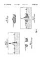
- FIGS. 1a through 1dare examples of the real-world scene, a virtual image, the resulting masked virtual image, and combined images, respectively.
- FIG. 2is a simplified block diagram showing the major steps in the present method.
- FIG. 3is an example of a range map generated by the range scanner.
- FIG. 4is an example of the virtual masking objects corresponding to the range map shown in FIG. 3.
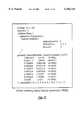
- FIG. 5is a VRML listing of a virtual masking object display construct representing one of the grassy knolls shown in FIGS. 3 and 4.
- FIG. 6is an example of the effect of implementing the virtual masking object defined in FIG. 5 on the virtual image of a cube behind the knoll and the virtual image of a sphere in front of the knoll.
- FIG. 7is an image combining the grassy knoll, cube, and sphere.
- FIG. 8is a listing of the equations used to implement time extrapolation for the virtual masking objects between range frame updates.
- FIG. 9is a three-dimensional example of a field of regard illustrating the use of time processing algorithms.
- FIG. 10is a pseudo-code listing of an algorithm for digital image combination.
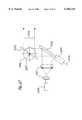
- FIG. 11is a simplified diagram showing one embodiment for injecting virtual images into a real-world scene.
- FIG. 12is a simplified diagram showing an alternative embodiment for combining a virtual image with a real-world image.
- FIG. 13is an example of a video image combining the virtual image from FIG. 6 with a real-world scene.
- FIG. 14is an example of a combined view of virtual tanks and the real world in the infrared as seen through the thermal viewer of a tank or infantry fighting vehicle.
- FIG. 15is an example of a combined view depicting virtual entities in a real-world scene.
- FIG. 16is a simplified block diagram of the reference apparatus showing one possible implementation of the present system.
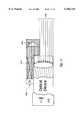
- FIG. 17is a simplified diagram of the transmitter section of the laser range scanner.
- FIG. 18is a simplified diagram of the receiver section of the laser range scanner.
- FIG. 19is a diagram of the scanning pattern for the laser range scanner.
- FIG. 20is a simplified block diagram of the virtual masking object (VMO) generation software.
- FIG. 21is an example of the control frame in the computer-generated image.
- FIG. 22is a simplified block diagram of the virtual simulation and control software.
- FIG. 23is a diagram demonstrating how an input laser beam can be steered using a crystal excited by an alternating electrical field.
- FIG. 24is a diagram illustrating passive optical ranging using two cameras to determine the range of an object.
- FIGS. 1a through 1dAn example of the basic functionality of the present invention is demonstrated in FIGS. 1a through 1d.
- the present systemcombines the image of a real-world scene (FIG. 1a) with a virtual image (FIG. 1b).
- the inventionprovides a method and the description of a reference apparatus and alternative implementations, to sense and remove elements of a virtual image, thereby generating a masked virtual image (FIG. 1c).
- the masked virtual image and the image of the real worldare then combined in such a manner that in the resulting combined image (FIG. 1d) the virtual object will appear to exist and move in the real world at its virtual position. While FIGS.
- FIG. 1a through 1dshow a battle tank
- the method of the inventionhas been also demonstrated using many other virtual objects, including animated human figures, geometric figures, or injection of three-dimensional building plans into a real-world environment.
- the methodis independent of the type of virtual entity generated, and it is also independent of the rendering and animation algorithms of these virtual entities.
- FIG. 2shows the major steps of the present method.
- One implementation of the present inventionis diagrammed in FIGS. 16 through 22.
- a range scanner 101determines the distance of the entities present in a real-world scene 102 within small ranging sectors.
- Each ranging sectoris defined as a small angular sector (e.g., 1 milliradian in height and width) and by its azimuth and elevation, seen from a momentary observation point.
- the ranging sectorsare included within the field of regard 103 of the range scanner 101. Scanning is limited in range, for example to 1000 meters. Range scanning may be performed by a laser range scanner (as in the reference apparatus shown in FIGS. 16-22) or by other means that can determine the distance of objects within the angular space of ranging sector.
- Range data 104are generated by the range scanning step, and include azimuth, elevation, and range to the nearest object for each ranging sector.
- Range scanningis an existing technology that provides range data necessary for virtual masking object generation. Normally, existing ranging systems will be used. The type of scanning will depend on the range and ranging sector requirements of a particular implementation of the invention for a specific application. For a range requirement of approximately 400 meters, and angular resolution of approximately 1 milliradian, a 905 nanometer eye-safe infrared laser scanner was sufficient in the reference apparatus.
- range scanningIn lieu of laser range scanning, other types of range scanning can provide sufficient range data for the present system. Examples of other scanning methods include three-dimensional radar scanning for longer ranges (multiple kilometers), or acoustical ranging for short ranges (e.g., within 50 meters). Active flash ranging methods, in which the acquisition of range for the ranging sectors is achieved in a simultaneous manner, covering the whole field of regard by phase-modulated laser or radar ranging flashes, or by multiple amplitude-modulated laser or radar pulses, are also applicable for short ranges. Passive ranging methods (e.g., stereographic or parallax comparison of real-world scene elements) can also be used, when their angular resolution fits the requirements of a specific application.
- Passive ranging methodse.g., stereographic or parallax comparison of real-world scene elements
- the frequency of range data updates imposed on the range scannerdepends on the type of real-world scene considered for specific implementations of the invention.
- a 266 Hz laser pulse ratewas used for scanning the static scenes considered for the reference apparatus in FIGS. 16-22.
- the field of regardwas scanned from a static observation point with approximately 26,000 ranging elements to provide a range frame update rate in the order of 0.01 Hz.
- range scanning pulse ratessuch as 30 KHz
- range frame update ratefor the field of regard in the order of 1 Hz or higher.
- Range, azimuth, and elevation datamay be provided directly for each ranging sector, or indirectly, by providing only the range in each ranging sector, the scanning row number in the case of horizontal scanning for each row, and a frame start and stop signal. In this case, the angular width and height of each ranging sector is also provided.
- Virtual masking object generation 105is a key step of the invention.
- the ranging data of the ranging sectorsare used to define the virtual masking objects 106 corresponding to real world objects.
- the range map obtained in a 0.261 radians wide and 0.096 radians high field of regard by a 905 nanometer wavelength infrared scanning laser, scanning an area of small grassy hillocks, a parked automobile van, and a treeis shown in FIG. 3.
- the range return for each 0.98 milliradian ⁇ 0.98 milliradian ranging sectoris encoded as a gray intensity value, longer distances are shown in darker shades. Areas of no return are shown in white.
- Such range mapsare raw data, normally requiring further processing.
- Rectangular virtual masking objectscan be generated from the raw data at the measured range, having the angular width and height of each ranging sector, to mask portions of the images of such virtual entities as may lie beyond this virtual masking object. This is one method within the scope of the invention for virtual masking object generation.
- Another, alternative approachis to apply a statistical filter to the raw ranging data in order to establish coherent, larger virtual masking objects (FIG. 4).
- the software code used for generating larger virtual masking objects, as shown in FIG. 4,is listed in Appendix A.
- the conditions for establishing coherence of virtual masking objects in the software code of Appendix Aare listed in Table 1. These conditions are associated with the specific method of ranging in the reference apparatus, which uses horizontal scan lines, advancing vertically from scan line to scan line.
- Alternative rulesmay be used for establishing the virtual masking objects.
- An example of an alternative methodis direct three-dimensional filtering. With this method, individual points defined by their ranging sector's azimuth, elevation and range are added to a virtual masking object as long as new points fall, within a pre-determined tolerance "t" on a common plane, and when such points are contiguous within the tolerance of a hole-filling algorithm.
- the above methodsresult in a geometrical definition of the virtual masking objects. These may be simple quadrangles for a single ranging sector, or complex agglomerations of many ranging sectors into a two or three-dimensional surface. Within the virtual masking object generation step, three additional functions are performed.
- Display construct generationbuilds data constructs compatible with a specific rendering system.
- the virtual masking objects shown in FIG. 4were prepared for presentation under the Virtual Reality Modeling Language (VRML), version 2.0 (International Standards Organization ISO/IEC CD 14772), using the "IndexedFaceSet" high-level virtual reality node specification. This is reflected in the last section of the software code in Appendix A written in the Java language. Other sections of the software code are generic and independent of the actual rendering system used. The invention itself is independent of any specific rendering implementation.
- VRMLVirtual Reality Modeling Language
- version 2.0International Standards Organization ISO/IEC CD 14772
- IndexedFaceSethigh-level virtual reality node specification
- Display attribute preparationis the last processing function of the virtual masking object generation step. This function may be separate from, or coincident with the display construct generation function, depending on the specific rendering system and image combination system used.
- the virtual masking objectsmust be rendered with display attributes that permit the automatic replacement of their pixels in the image combination step with a video background representing the external world. This attribute depends on the specific image combination hardware, and is usually referred to as the background attribute.
- the VRML 2.0 display construct and background display attribute of one of the grassy knolls shown in FIGS. 3 and 4is listed in FIG. 5.
- the background attributeis set as the ambient intensity, diffuse color, and shininess values in the material node of the construct, and corresponds to values set for a DeltaScan Pro GL GenLock system for image combination.
- Other image combination systemsmay use different attributes, such as a specific blue background color.
- any particular rendering systemsuch as the Virtual Reality Modeling Language
- the method describedwill work with any rendering system capable of rendering three-dimensional objects, or two-dimensional projections of three-dimensional objects.
- VRMLis used for virtual object definition in the reference apparatus, rendered through VRML browser software.
- FIG. 6The effect of implementing the virtual masking object described in the VRML display construct of FIG. 5 is shown in FIG. 6.
- the grassy knoll of FIG. 5is approximately 45 meters from the origin of the coordinate system located at the observation point of the user of the invention.
- the masking effect of FIG. 6is obtained, assuming a white background attribute.
- the actual virtual objects present in the scene, including the grassy knoll's virtual masking object,are shown in FIG. 7.
- Time processing algorithmsare used for dynamic scenes in the virtual mask generation step in cases when the range frame rate achieved by the range scanning is not sufficient to provide the illusion of continuous motion (25-30 Hz range frame rate) of the virtual masking objects.
- range frame rateachieved by the range scanning
- single-beam sequential scanning methodswhich are normally used for long ranges of several hundred meters to multiple kilometers to establish a range map
- the achievable range frame rateis limited by the speed of light.
- a sequential ranging systemsuch as the laser range scanner used in generating FIG. 3, limited at 1500 meters range, has an out-and-return time frame of 10 microseconds for the range scanning laser pulse for each ranging sector. In this case this results in a minimum possible frame update time of 0.26 seconds, or a maximum possible range frame rate of 3.83 Hz. Practical considerations of actual ranger electronics implementations make the achievable range frame rate lower than this theoretical limit.
- the time processing algorithmslinearly extrapolate the advance of the vertices of existing virtual masking objects to obtain the intermediate geometry of these objects between range frame updates obtained by range scanning.
- the time processing extrapolation algorithmswill be executed normally at a lower frequency than the maximum update rate of 25 to 30 Hz required for the illusion of continuous motion.
- the extrapolation algorithmscan be invoked by control algorithms on an as-needed basis.
- the logical conditions for invoking and controlling time processingare listed in Table 2.
- a set of three dimensional "envelope points"e.g., the ranging sectors of maximum and minimum azimuth and elevation are selected at the time of acquisition of each virtual masking object for implementing the conditions of Table 2.
- FIG. 9illustrates the logic conditions of Table 2. It shows several virtual masking objects, including the apparent terrain 130 observed by range scanning, and other virtual masking objects 131, which include Object A located near to the observation point, and Object B located at the extreme range of range scanning.
- the envelope points for each virtual masking objectare also indicated as black dots in FIG. 9.
- the angular position of the envelope points of Object Ais assumed to have changed between the last two frame updates as shown by the arrows. If the angular movement of the left-side envelope points of Object A exceeds two ranging sectors (or a minimum number of ranging sectors as specified for a particular implementation) the extrapolation code will be invoked at least for some of the vertices of Object A by the invocation logic.
- Time processing algorithmsdo not need to be implemented at all in those applications of the invention in which the observation point of the user of the invention is static, and the real-world field of regard of interest does not contain moving real-world entities.
- the method of virtual masking object generationis an element of the overall method of the invention, the specific form in which the virtual masking objects are implemented depends on what existing method of virtual object generation and rendering is used in a particular implementation of the present system.
- the example of FIG. 5uses the Virtual Reality Modeling Language (VRML).
- VRMLVirtual Reality Modeling Language
- IEEE 1278-1995a Distributed Interactive Simulation Standard
- virtual masking objectsare updated through nodes injected by Java code, shown in the computer code listings of Appendix A.
- the virtual masking objectsmay be generated as Entity Appearance Protocol Data Units, or Dynamic Terrain updates.
- the method of virtual masking object generationis compatible with any virtual entity generation and rendering method.
- Virtual entitiesmay be simulated, by the animation and control techniques available through the Virtual Reality Modeling Language (VRML).
- VRMLVirtual Reality Modeling Language
- An example of this approachis shown in the listing of Appendix B, in which three battle tanks are animated.
- the virtual simulation techniques defined in the Distributed Interactive Simulation Standard(IEEE 1278-1995) may be utilized.
- Virtual entity simulationgenerates continuously virtual entity appearance data (108 in FIG. 2).
- the virtual entity appearance dataare updated through animation code implemented as ROUTE constructs, Script nodes, or nodes generated through Java code.
- the Distributed Interactive Simulation Standardis used, the virtual entity appearance data are generated as Entity Appearance Protocol Data Units.
- the inventionis compatible with any virtual entity simulation.
- the virtual entity appearance data generated by the virtual entity simulation and the virtual masking objectsrenders the virtual entity appearance data generated by the virtual entity simulation and the virtual masking objects.
- the rendering processitself depends on the particular implementation of the present system. It can be implemented using existing technologies, such as VRML, or the Distributed Interactive Simulation Standard (IEEE 1278-1995), or other, commonly available virtual entity rendering methods.
- the virtual entity appearance dataresult in virtual images rendered in their normal appearance attributes, that is in their color, texture, intensity and other attributes as defined in the virtual entity simulation.
- the virtual masking objects, and all background of the virtual sceneare rendered in the background attributes compatible with the image combination techniques used in the image combination step.
- the virtual image generation step 109renders masked virtual images, in which those elements that would be masked by natural objects are missing from the images of the virtual entities rendered from the virtual entity appearance data, as shown in FIGS. 1c and 6.
- the virtual images constructed in the virtual image generation step 109are combined with the real-world image 114 originating from the video camera 100.
- the inventionis not limited to observing the real world in the visible spectrum.
- the video cameramay operate in the ultraviolet or infrared range, and it may be replaced by a sensor such as a radar device, when the user of the system wishes to obtain a real-world image in a non-visible spectral region.
- the field of regard 103 of the camera 100coincides approximately with the field of regard of the range scanning 101.
- the image combination steputilizes commercially available hardware, together with commercial or specially-built software for combining the virtual images with the real-world image.
- the video imagewill fill out all areas of the display 111 rendered in the background attribute.
- a feasible technique to implement this stepis to use a video "GenLock" board, such as a DeltaScan Pro GL used in the reference apparatus, setting the background attribute to 0 intensity, and black color, as shown in the code example of FIG. 5.
- a video "GenLock” boardsuch as a DeltaScan Pro GL used in the reference apparatus, setting the background attribute to 0 intensity, and black color, as shown in the code example of FIG. 5.
- the real-world imageis supplied as digital video or a digital sensor's data stream, the pseudo-code shown in FIG. 10 will implement the appropriate image combination.
- Image injectionis an optional method of image combination, to be used when the observer 113 would normally observe the real-world scene through an instrument, such as the gunsight of a tank or the optics of a camera.
- Two alternatives of image injectionare virtual image injection (FIG. 11), and combined image injection (FIG. 12).
- the virtual image output 140 of virtual image generationis displayed through a color video projector 141. It is then focused at infinity through a collimator 143 and prism 144 and injected into the collimated field of an optical device (such as the gun sight of a battle tank, the optical train of a motion picture camera, or the optical train of any other optical device used for viewing the combined image) normally showing only the real-world image 145.
- an optical devicesuch as the gun sight of a battle tank, the optical train of a motion picture camera, or the optical train of any other optical device used for viewing the combined image
- the observer 146 using the optical devicewill see the virtual image over the whole field of view of the real-world image.
- the combined image 153is generated from the virtual image 150 and real-world image 151 in a color video display projector 152, which provides the input into an optical display device, such as an advanced gun sight that uses video input as its image source, or the optical train of a motion picture camera.
- the output of the image combination stepis shown in the display 111 of the combined image 112 in FIG. 2, presented to the observer 113.
- the display 111may be any display system capable of displaying the combined image, such as a video display, an electronic goggle or visor, a video projector, the display screen of an electronic device such as a game, instrument, or sensor, or the optical train of a display and recording device, such as a camera.
- An example of a combined image display, using a VGA monitor in a 16-bit color depth, 640 ⁇ 480 pixel display modeis shown in FIG. 13.
- the virtual image of FIG. 6, with the grassy knoll's masking objectwas combined with a live video scene obtained as an S-video signal from a color video camera.
- the live sceneincludes the live original of the grassy knoll, which appears to be masking out a portion of the virtual cube, while the virtual sphere is rendered with no masking.
- Alternative display implementationsare compatible with the method. These may include flat display panels, image projectors, or virtual reality goggles or visors worn by the observer. In cases when the observer would normally observe the external world through an optical or other instrument, the virtual images can be injected into this instrument, as described under image injection. In the case of virtual reality goggles or visors, two fields of view may be presented corresponding to what is seen by the left and right eye of the user of the system.
- FIG. 14shows a combined view in the infrared, as it may show up in the thermal viewer of a modern battle tank or infantry fighting vehicle.
- the virtual entities generated by a virtual entity simulationdo not necessarily represent a real-world object. For example, they may represent fictional characters or entities, or views of conceptual objects. An example of conceptual virtual entities is shown in FIG. 15.
- the real-world objects 170include the terrain, a tree, and a battle tank, in which the observer or observers 171 of a combined reality view presented to them are located.
- the conceptual virtual entities in the figureare conceptual objects: a path marker 172, a unit boundary 173, a navigational marker 174, and a phase line 175.
- the present systempositions the conceptual virtual entities in the display in such a manner that they appear to be present in the landscape visible to the observer(s).
- the observer 113 of the displayis assumed to be the user of the invention for various purposes, such as military training, or entertainment.
- the observermay interact with the apparatus implementing the invention through observer actions 120 in FIG. 2.
- Observer actionsinclude the observer's interactions with virtual elements in the combined reality scene.
- An example of such direct interactionis the engagement of a virtual opponent from a combat vehicle, such as a battle tank.
- the observerthe battle tank's gunner or commander
- This virtual-live interactionwill take place by the observer's actions being captured through the observer's sensors and controls 115 in FIG. 2.
- Observer actionsalso include interactions of the observer with the real world, such as head movement of the observer, the observer's use of the battle tank's fire control system controls, or the actual firing of the gun through a trigger.
- the observer's interactions with the real worldalso include the movement of the observation point (in the case of a battle tank, the movement of the vehicle and rotation of the turret), and the resulting changes of three-dimensional position and attitude.
- Observer actions that are relevant to virtual-live interactionsmay also include the steering of a vehicle housing the observer, or manipulation of control devices such as joysticks or pushbuttons applicable to a specific implementation of the invention.
- Observer actions in the virtual-live interoperationsinclude magnification (zoom) control of a simulated battle tank gun sight, the tracking of a specific virtual tank, and engagement of a virtual tank being tracked through the simulated gun sight. They also include scenario selection, scenario start, stop, and re-start. All observer actions are sensed by the various components classified as observer sensors and controls 115.
- Observer sensors and controls 115are devices using existing technology, and no specific observer sensor or control is claimed as an element of the invention.
- the position and orientation of the observeris sensed by observer sensors and controls 115 such as a magnetic or infrared head tracker system used in conjunction with virtual reality goggles.
- Observer controlsalso sense any signals received directly from the observer, such as changing the optical magnification of a gun sight, or manipulating fire control system controls.
- Observer's sensor and controlsnormally include displays or signals resulting from feedback from the virtual simulation, such as virtual battle damage.
- GPS survey and optical line-up with surveyed landmarksare used to determine the observer's position and the direction of the scanner and camera optical axes.
- Observer controlsinclude software-implemented pushbuttons, option selection buttons, and selections from lists of multiple choices, displayed on a color VGA screen, and activated by a mouse control device.
- the signals generated by the observer sensors and controlsare stored and processed by the Observer State and Action Processing step 116 in FIG. 2.
- State vectorsthree-dimensional position, angles, velocity, and angular velocities
- Observer actions sensed by the observer's sensor and controlsare transformed into data or control signals appropriate for responding to the observer's actions.
- Table 3some of the observer actions processed by the present system are listed in Table 3:
- Observer action processingmay interact with the scanner and camera controls. For example, when the magnification level of the simulated gun sight is changed by the observer, the video camera's 100 zoom level is changed through the observer state and action processing software, by sending a control signal 118 to the camera's electronic control board, which in turn changes the zoom lens position.
- Changes in the position and orientation of the observer, of a vehicle housing the observer, or of movable elements of the vehicle (e.g. a tank's turret) as sensed by the observer's sensors and controlsare processed by the observer state and action processing step.
- the virtual entity simulationreceives this information for updating the simulation, in which the avatar of the observer, or the avatar of the observer's vehicle is represented.
- Both the virtual entity simulation and the virtual masking object generation functionwill respond to the position and attitude changes of the observer, or the observer's vehicle. Such changes will affect the angular orientation of the virtual entities and virtual masking objects, and the apparent distance from observer to virtual entities and masking objects.
- Changes in the head position of the observer in some implementations of the inventionwill control the optical axes of the video camera and range scanner, to ensure that scanning and real-world scene acquisition coincides with the observer's current field of view.
- the observer's sensors and controlsinclude signals acquired from a vehicle, such as the fire control system information acquired through a data bus in a battle tank housing the observer, this information is also processed in this step. For example, in computing whether a virtual opponent was actually hit by fire from the host vehicle's main gun, the fire control system data available from the vehicle bus are utilized. The result of such calculations is then fed to the virtual entity simulation to provide damage information.
- Information fed back from the virtual simulationis also processed in the observer's state and action processing step. For example, if one of the virtual tanks represented in this simulation engage the avatar of the observer's tank, the resulting damage information will activate damage displays, or a "killed" indicator in the observer's sensors and controls suite.
- FIG. 16is a simplified block diagram of the reference apparatus showing one possible implementation of the present invention.
- the real-world scene 216is observed through a video camera 200, and it is range scanned with the laser scanner.
- the video camerais a commercially available remote-control camera.
- the video cameracan be moved in pitch and yaw (pan motion), and also zoomed through a nominal magnification range of 1.55 ⁇ through 10 ⁇ magnification.
- These functionsare activated by the digital control signals sent to the camera's internal control board through an RS-232 camera control cable 202.
- the internal control boardin response to these signals, activates the camera's zoom, pitch, and pan motors.
- the cameraalso senses the current zoom, pan, and pitch values, which are used by the internal control board as feedback signals, and are available through the camera control cable 202 for external processing.
- the video signalin the S-video analog format, is acquired from the camera through the video cable 201, which connects to the video mixer through its S-video input port.
- the laser scanner 203is a modification of a commercially available solid-state infrared surveyor's ranging laser, operating at 905 nanometer wavelength, sending out 40 nanosecond repeated laser pulses at 47 wafts peak power. Range is determined by measuring the time differential between start of a pulse, and the start of the reflected return signal, separated from ambient light by a narrow band filter. Modifications made to the laser unit's electronic control board made by the manufacturer have set the pulse rate at 266 Hz for range scanning use.
- the laserin normal surveying operations, without the use of retro-reflectors, has a maximum range of approximately 1200 m. This range is reached by processing multiple returns from the same target, and utilizing a set of logic functions which disregard uncertain returns.
- the laserhas separate sending and receiving apertures.
- the scanner elementsare built from commercially available components, as shown in the schematics of FIGS. 17 and 18.
- the transmitter section of the laser scannerreflects the laser beam 228 originating from the laser diode 220 and focused through the lens system 221 of the commercial laser unit through a horizontal scan mirror 222 and a vertical scan mirror 225.
- the horizontal scan mirroris mounted on a shaft, which rotates around the horizontal scan axis 224, driven by the horizontal scan motor 223 in steps equal to 1/2 of the horizontal angular width of the ranging sector (approximately 0.49 milliradians).
- the horizontal scan mirrordoubles the relative incidence angle of the laser beam, resulting in horizontal scan steps incremented by the horizontal angular width of the ranging sector.
- the direct current stepping motoris controlled through the electronics unit 205 in FIG.
- Time marks corresponding to the laser firing signalsare transmitted through the RS-232 scan control cable 204 from the laser's built-in electronic control board to the electronics unit of the apparatus 205.
- the electronics unitcommands the steps of the horizontal scan motor.
- the timing of the electronics unit commands to the scan motoris generated so that it precedes the next laser pulse firing by approximately 15% of the cycle time between laser pulses, providing adequate settle time for the horizontal scan mirror.
- the horizontal scan mirroris a 15 mm diameter circular mirror, controlling a laser beam of approximately 8 mm in diameter, and expanding at an angle of 0.98 milliradians.
- the horizontal scan mirrorperforms a linear nodding motion about the horizontal scan axis. After completing a horizontal scan line of 266 steps, the next scan line proceeds in the opposite direction after the laser beam's elevation is changed by the vertical scan mirror.
- the resulting scanning patternis shown in FIG. 19.
- the vertical scan mirror 225is stepped by half of the vertical angular height of the ranging sectors (approximately 0.49 milliradians) upon the completion of each horizontal scan line.
- the vertical scan mirror, driven by the vertical scan motor 226is mounted on a shaft that rotates about the vertical scan axis 227, which is perpendicular to the horizontal scan axis.
- the steps of the vertical scan motorare controlled by the electronics unit 205 through the scan control cable 204. Each vertical step is activated in response to an opto-mechanical interrupter connected to the horizontal scan mirrors.
- the mechanical element of the interrupterinterrupts a light beam incident on a commercially available photo-electronic sensor, which in turn interrupts an electronic signal sent to the electronics unit through the RS-232 control cable.
- the elevation of the outgoing laser beam 228is raised by an angle corresponding to twice the angular step of the vertical scan mirror, resulting in the scanning pattern shown in FIG. 19.
- the control logic of scanningis summarized in Table 4.
- the receiver section of the laser apparatusis closely integrated with the transmitter section.
- the incoming laser reflection 233is reflected through the vertical scan mirror 232, and the horizontal scan mirror 231, into the sensor cell 230 of the laser electronics unit.
- the vertical scan mirroris mounted on a shaft rotating about the vertical scan axis 227. This is the same shaft, rotating about the same axis as the one mounting the vertical scan mirror of the transmitter section.
- the angles of vertical scan mirrors of the transmitting and receiving sectionsare therefore always at the same angle, except for dynamic transients of shaft rotation at their respective mounting points, resulting from the shaft's response to the motor steps.
- the horizontal scan mirror of the receiver sectionis also on a common shaft with the horizontal scan mirror of the transmitter section, rotating about a common axis 224, driven by the same horizontal scan motor 223.
- the lens system 234 and the sensor cell of the receiver sectionare standard elements of the commercial laser range finder used in the laser range scanner.
- the distance of the object causing the laser reflectionis measured by the electronics section from the time difference between firing the outgoing laser beam 228 (in FIG. 17), and the laser reflection.
- the laser scan pattern of the reference apparatusis shown in FIG. 19.
- Six horizontal scan linesare shown. Each scan line is composed of 266 scan steps.
- the arrows on the scan linesshow the direction of advance of scanning for each scan line.
- the scan frame for this implementationis defined as the 98 successive scan lines implemented by the apparatus. Successive scan lines proceed from the highest azimuth at the top of the scan frame to the lowest azimuth at the bottom of the scan frame. Upon completion of the scan frame the scan starts with a new scan frame, at the top of the scan frame.
- the laser range data signalsresulting from each laser pulse-reflection sequence, are delivered through the standard RS-232 laser signal cable 206 in FIG. 16 to the laser scanner control computer 208. These signals may be, at the option of the operator, displayed by the laser scanner control computer in Display A 209 in FIG. 16, (e.g., a VGA display) as range maps, such as shown in FIG. 3.
- the laser range data signals received by the laser scanner control computerare re-formatted to the laser data format of the reference apparatus for transmission to the virtual simulation computer 210 through the RS-232 laser data cable 217.
- the laser data format used in the implementation of the invention outlined in FIG. 16is described in Table 5. The invention itself is independent of any specific data format used for transferring range scan measurements.
- Start and stop commands for starting up the laserare transmitted to the laser range scanner directly from the laser scanner control computer through the RS-232 laser signal cable 206.
- Scanner motor start and stop commandsare transmitted from the laser scanner control computer through the RS-232 interface control cable 207 to the electronics unit 205, which executes the stepper motor control programs. These programs, in turn, generate the detailed stepper motor control signals sent to the laser range scanner through the scan control cable 204.
- VMOvirtual masking object generation
- a virtual simulation computer 210e.g., a personal workstation running two 266 MHz Pentium II processors.
- the processing flow of the VMO generation softwareis indicated in FIG. 20.
- Appendix Acontains the listings of the key software routines implementing this processing flow for the reference apparatus.
- the laser ranging dataformatted in the laser range data format (Table 5), are received by the virtual simulation computer 210 shown in FIG. 16 through a serial port, and are processed by a standard communications processing module 241 shown in FIG. 20.
- the communications processing module 241places the laser ranging data into a global memory buffer module 242.
- a global memory interface module 243fetches the laser ranging data for each consecutive ranging sector for processing by the virtual blade object generation module 244.
- This moduleagglomerates adjacent ranging sectors on the same scan line into virtual blade objects, by implementing the rules for virtual blade object generation shown in Table 1.
- the processinggenerates an array of virtual blade objects, which are then processed by the virtual masking object (VMO) generation module 245, which implements the VMO generation rules of Table 1.
- the data arrays defining the border points of the VMOsare then read by the VMO VRML construct generation module 246, which assembles data strings describing the individual VMO.
- An example of VMO strings generated by this moduleis shown in FIG. 5.
- These VMO stringsare passed by the VMO VRML construct generation module into the current virtual scene for VMO rendering 247.
- the current virtual sceneincludes the virtual entities generated by virtual entity simulation (107 in FIG. 2).
- the computer-generated imageis transmitted to the video mixer 213 through the virtual display cable 212 (e.g., a VGA/SVGA computer display cable).
- control frame shown in FIG. 21is shown above the virtual scene in the computer-generated image. It is implemented by the Java and VRML-capable browser running the Java applet code for VMO VRML construct generation, and rendering the virtual scene, as indicated in the code listings of Appendix B.
- Virtual entity simulationis implemented in the virtual simulation computer through the virtual simulation and control software.
- the processing flow of the virtual simulation and control softwareis shown in FIG. 22.
- Appendix Acontains the listing of the key modules of the virtual simulation and control software.
- the observer's command interfaceis implemented in the HTML control frame 251 (shown in detail in FIG. 21) through the various selection lists and control buttons.
- the observer's control actionsresult in the execution of Javascript command messages 252.
- the Help button in the control frameinvokes a stand-alone, floating HTML help page, and the Tech Panel button invokes a separate control frame for adjusting Display B.
- These two controlsare not relevant to the method disclosed, and their functions are not discussed further, except to remark that the Tech Panel controls implement boresighting of the virtual, video, and laser scenes.
- the Select Scenario list, and Start and Reset buttons in the control frameexecute control functions related to the virtual simulation only. The code sequences resulting from activating these controls are listed in Appendix B.
- Select Scenarioselects one of several available scenarios for the behavior of the virtual entities being simulated (in this case T-80 main battle tanks). Other scenarios not related to tanks, or military training, can be selected by a user of the reference apparatus after minor modification of the VRML data, and the labels of the scenario control list.
- the Start and Reset buttonsstart and reset a selected scenario.
- the Zoom Control list box, the AutoTrack check box, and the Fire button in the control frameemulate some of the functions of the controls available to the gunner of a main battle tank, or to the gunner in a tank simulator, for engaging the virtual T-80s operated by the virtual simulation.
- a Javascript command message 252is executed, which in turn, invokes the command transfer 253 functions in a Java applet.
- the command transfer functionexecutes the code in a dynamic link library (DLL) for camera commands 255, and also a VRML script function for VRML command execution 254.
- DLLdynamic link library
- VRML script functionfor VRML command execution 254.
- the camera command functionsensure that the scene displayed by the video camera and the VRML-generated virtual scene are displayed at the same magnification. All other control objects in the control frame interact only with VRML command execution.
- the VRML command execution script functionsactivate changes in the Virtual Animation and Rendering 256 elements implemented in VRML.
- the virtual animation and rendering functionrenders and displays the virtual elements of the computer-generated image 248, which also contains the virtual masking objects.
- the computer-generated image 248may be optionally displayed in Display B 211 in FIG. 16.
- the computer-generated imageis transmitted to the video mixer 213 through the virtual display cable 212 (e.g., a standard VGA/SVGA computer display cable).
- the virtual entities implemented by the virtual simulation and control softwareare capable of engaging the avatar of the observer's vehicle, depending on the scenario loaded in. In the reference apparatus, in which the observer's position is assumed to be static, the avatar of the observer's vehicle is implicitly located at the observer's VRML Viewpoint node coordinates.
- the VRML route nodes describing the motion of the virtual entitiesare generated automatically by a route generation 257 module (written in Visual Basic and Java).
- the route generation moduleis regarded as a support module of the visual simulation, generally implementing existing technology, and will be described separately.
- Image combinationis implemented through the video mixer 213 (in FIG. 16), a commercially available DeltaScan Pro GL GenLock unit.
- the S-video format analog video image of the real-world scene generated by the video camerais delivered to the video mixer by means of the video cable 201, a standard and commonly available S-video cable.
- the computer-generated image resulting from the virtual masking object generation and virtual simulation and control functionsis a standard VGA or SVGA color image generated with 16-bit or 24-bit color pixels (depending on settings in the virtual simulation computer). This image is delivered to the video mixer through a standard, commonly available VGA/SVGA cable.
- the background color used in the reference apparatusis black (0,0,0 RGB values), with 0 intensity.
- the video imageshows up as the background image, that is, in all areas of the computer-generated image rendered with these attributes. This results in the combined reality scene showing virtual entities in the real world, the objective of the invention.
- the output of the video mixeris an S-video signal, available through the S-video feed cable 214 (in FIG. 16), a standard S-video cable.
- the available settings of the video camera and the video mixeralso permit the use of a standard NTSC composite video signal, in which case the S-video compatible cables are replaced by a standard NTSC video cable.
- the display function of the combined reality scene in the reference apparatusis implemented through an S-video display.
- the observer of the reference apparatusis at a static position, observing the combined reality scene through a simulated gunsight of a main battle tank.
- observer controlsare those on the control panel (FIG. 21).
- a Global Positioning Satellite (GPS) receiver, with optional differential correction, and an aircraft altimeterdetermine the three-dimensional position of the observer. Alignment of the apparatus with the vertical in is assured through two bubble levels.
- the azimuth of the boresight axisis determined with the help of landmarks, a telescope attached to the laser scanner housing, and a calibrated compass azimuth ring.
- Observer action processingtakes place through the software responding to control panel actions.
- Generation of geographical information and virtual entity movement and alignment informationtakes place through the use of a route generation module, operated in advance of using the apparatus.
- the route generation module 257is an inter-operating collection of software written in Visual Basic and Java. It supports the virtual simulation and control, and observer sate and action processing functions. It is a supporting module of the reference apparatus, which can be implemented without operating this module. Only the summary of the operation of the route generation module is described, on the basis of which an equivalent software module can be developed by a programmer familiar with its implementation languages, VRML, and the US Geological Survey Digital Elevation Model (USGS DEM). The VRML route nodes describing the motion of the virtual entities are generated automatically by the module.
- the terrain preparation component of the modulereads in USGS DEM digital terrain files 258 that include the observer's location, and generates a VRML elevation grid from the USGS DEM data.
- the route builder component of the moduleautomatically prepares three-dimensional VRML position and orientation interpolator nodes for the scenario from the VRML elevation grid and routes overlaid on a map display by the observer. These nodes are read at simulation start time by a Java command transfer function, which injects them into the VRML content of the virtual simulation (implemented through the VRML command execution, and virtual animation and rendering functions).
- the VRML elevation grid derived from the USGS DEM datausually does not correspond exactly to the terrain visible through the video camera 200 (FIG. 16), or sensed by the laser scanner 203.
- the Virtual Masking Objects (VMOs) built by the VMO VRML construct generation module 246 (in FIG. 20), and digital scene files 259can be read by the correction component of the route generation module.
- the digital scene filesare video snapshots received from the video camera and saved as standard JPEG or BMP files.
- the direct video feed from the video cameracan be used to edit the VRML terrain grid.
- the virtual image of the terrain griddisplayed by the Java component of the route generation module, is mixed, through the video mixer 213 with the video image of the corresponding terrain in the S-Video display 215.
- the controls of the route generation softwarein this case permit the direct manipulation of each point on the terrain grid.
- the range of the ranging sectors within the field of regard of a range scanning devicemay be determined by other means besides laser scanner devices as described for the reference apparatus.
- the angular extent of the ranging sectors in radiansis limited by the ratio of wavelength to transmitter aperture (reflector, antenna, or lens). This limitation also applies to acoustic ranging.
- a practical scanner alternative to a laseris the use of currently emerging 77 GHz automobile collision avoidance radars, as well as other millimeter-wave radar devices.
- tis greater than approximately 0.03 seconds
- the virtual masking object time processing extrapolation methodssuch as shown in FIG. 8, must be invoked for dynamic real-world scenes.
- n288,000, limiting the value of r to 15.6 meters with electromagnetic scanning.
- These relationshipsalso mean that sonic scanning of dynamic scenes, in essence, will always require the use of extrapolation algorithms.
- the limiting factor in the case of sonic scanning in dynamic scenesis the scan frame repetition rate. Estimating the minimum acceptable ranging sector size as approximately 1 degree in azimuth and elevation, the scan frame repetition rate is approximately 0.5 Hz at a 4-meter range. Scan frame repetition rates below this value are unlikely to provide adequate information for realistic extrapolation.
- Step-by-step ranging using electromagnetic scanningcan provide high-resolution virtual masking for longer ranges without extrapolation when the optical axis of the range scanner is coupled to a sensor tracking the foveal motion of the observer.
- a sensor tracking the foveal motion of the observerSuch sensors are available in experimental and military systems.
- the foveal zoneis less than 3 degrees in angular extent. It is the only zone within which fine details are observed by the human eye.
- foveal motion-coupled optical or electromagnetic range scanningcan be performed without the need for extrapolation up to a range of approximately 1700 meters.
- a second scanner, operating at a different wavelengthmay then cover the whole visual field at the same range without the need for extrapolation with ranging sectors of approximately 1 degree of angular extent.
- High frame rate sequential scanningrequires high-frequency beam steering methods.
- the required horizontal mirror rotation frequencyis approximately 100 Hz. This can be achieved by mechanical means.
- higher frequenciescan be achieved by laser-transparent crystals excited by alternating electrical fields (FIG. 23).
- Beam deflection amplitude by this methodis limited approximately to ⁇ 1.5 degrees.
- the limited scan angles of the various high-frequency beam steering methodscan be multiplied by reflecting mirrors, each mirror multiplying the angle by a factor of two.
- Active flash ranging methodsare based on illuminating a scene simultaneously with ranging pulses covering the whole field of view of interest, and receiving the return reflection through a lens system directing the reflection to a CCD sensor matrix device.
- the practical embodiment of laser ranging devices built using this methodused additional range discrimination besides return time discrimination, such as multiple amplitude-modulated ranging flash pulses, or frequency-modulated ranging flash pulses.
- Flash rangingpermits the generation of virtual masking objects without extrapolation.
- the limitation of this methodis in its large power requirement for large fields of regard, which, in turn, limits its practical range to around 100 meters.
- Passive ranging methodsare based on parallax measurements of ranging sectors (pixels) in coaxial CCD matrix cameras with parallel optical axes separated by a known baseline (FIG. 24).
- the identification of ranging sectorsmay take place by comparison of individual pixel color and intensity values, or by identifying each pixel through its return reflection of a laser scanning beam through a hybrid passive-active ranging approach.
- the methodis compatible with high-speed, parallel hardware level processing.
- the inventionis not limited to such applications; it can be applied with equal efficacy to inserting virtual elements into films in an automated manner, displaying the appearance of potential construction in its planned exterior or interior site, or as an interactive, recreational device. It can be used as an interior decorating or arrangement planning and demonstration aid, or as an aid showing the potential effects of reconstructive surgery or dental work.
- the method disclosedis capable of supporting such applications, or other implementations in which virtual, computer-generated scenes must appear to fit seamlessly into a real-world environment.
Landscapes
- Physics & Mathematics (AREA)
- Engineering & Computer Science (AREA)
- Computer Graphics (AREA)
- Geometry (AREA)
- Software Systems (AREA)
- General Physics & Mathematics (AREA)
- Theoretical Computer Science (AREA)
- Processing Or Creating Images (AREA)
Abstract
Description
TABLE 1 __________________________________________________________________________Example of rules to generate virtual masking objects Function Condition __________________________________________________________________________Define zero, one, or more coherent Add new ranging sectors to the current virtual virtual objects within each scan blade object as long as the individual ranging line, having an angular height of sectors fall on a straight line within tolerance "d0" one ranging sector (objects referred (for example, 1% of the range, and no less than the to as virtual blade objects). scanner's ranging error) as computed by a least- squared error algorithm. Identify the virtual blade objects Add new virtual blade objects to a virtual masking that belong to a common virtual object as long as the end points fall into a common masking object. plane within tolerance "d1" as computed by a least-squared error algorithm, and the virtual blade objects added are adjacent virtual blade objects already within the virtual masking object. Filter the edges of virtual masking Build straight line edges for the virtual masking objects to remove unnecessary objects, remove intermediate vertices which fall on vertices. a straight line edge within tolerance "d2" as computed by a least-squared error algorithm Limit virtual masking object size to Limit virtual masking objects to "n" (for example, that appropriate for fast rendering. 50 or 100) vertices. Remove holes from virtual masking Fill in spaces of one ranging sector between objects. adjacent virtual blade objects if the virtual blade objects otherwise fall into a common plane. __________________________________________________________________________
TABLE 2 __________________________________________________________________________Time processing algorithm invocation logic Function or Action Condition to Invoke Function or Action __________________________________________________________________________Do not activate time processing Observation point is static and there are no moving real-world entities in the scene Decide to compute time processing When movement of vertex is larger than a frequency for the extrapolation of predefined minimum number of ranging sectors vertices of virtual masking objects. during the previous frame update, compute time processing frequency as number of ranging sectors swept by the vertex during previous frame update. Frequency is limited by maximum desired update rate (e.g. 30 Hz). Decision to re-render a virtual If one or more vertices of virtual masking object masking object are re-computed by time processing. __________________________________________________________________________
TABLE 3 __________________________________________________________________________Examples of observer action processing Observer Actions Effect of Observer Action Implementation and Reference __________________________________________________________________________Tracking of Virtual Simulated gunsight reticle Autotrack software sequence in Targets by selecting placed on target, reticle Appendix B. Autotrack button automatically follows target. Fire gun at virtual Engage target being auto- Engage software sequence in target tracked Appendix B. Change gunsight Change simulated gunsight Zoom change software sequence magnification magnification in Appendix B. Select, start, pause, Selects and controls a Scenario control software stop scenario scenario in virtual simulation sequence in Appendix B. __________________________________________________________________________
TABLE 4 __________________________________________________________________________Laser Scanner Control Logic Scanner Action Control Logic __________________________________________________________________________Laser pulse fire 266 Hz repetition rate Increment horizontal scan angle (azimuth) Follow laser pulse firing signal with sufficient time, as a minimum, for laser out-and return at maximum range. Precede laser signal with sufficient settle time for step motor-mirror subsystem Terminate horizontal scan line Respond to opto-mechanical interruptor Increment vertical scan angle (elevation) Follow termination of horizontal scan line Initiate new horizontal scan line Follow elevation increment, reverse horizontal scan direction Terminate scan frame After last horizontal scan line complete Initiate new scan frame After termination of frame, if new frame start command is received __________________________________________________________________________
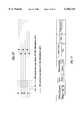
TABLE 5 __________________________________________________________________________Laser Data Format Data Implementation __________________________________________________________________________Serial Communication Parameters: 14400 Baud, No parity, 8 bits, 1 stop bit Start frame, upper left corner of scan frame "BFU" Start frame, lower right corner of scan frame "BFD" Range value scaling for frame starting now "SC = x.xxx" Start next scan line No. ddd "SLddd" End of current frame "EF" Range data following "SLddd" Scaled binary range of two bytes for each measurement. Both bytes have a "Byte Indicator Bit" at the high bit: raised (1) for the high byte, low (0) for the low byte. Positional values of range data bytes, "Low" byte 64 32 16 8 4 2 1 providing a numerical range of 0-16383 "High" byte 8192 4096 2048 1024 512 256 128 Application of Range Scaling Factor Multiplier for the values transmitted by the range data bytes. __________________________________________________________________________
TABLE 6 __________________________________________________________________________Correlation of the Method of Invention with the Reference Apparatus Step or Element of the Implementation in the Method of the Invention References Reference Apparatus References __________________________________________________________________________Range Scanning 101 in FIG. 2 Laser Scanner (203), FIGS. 16, 17, Electronics Unit, 18 and 19, Tables 4 and 5Video Camera 102 in FIG. 2 Video Camera (200) FIG. 16Virtual Masking Object 105 in FIG. 2, Virtual Masking Object Appendix A, Generation FIGS. 3-9, Generation Software in 210 in FIG. 16, Tables 1-2 Virtual Simulation FIG. 20 Computer Virtual Entity 107 in FIG. 2 Virtual Entity Simulation FIGS. 21-22 Simulation and Control SoftwareVirtual Image 109 in FIG. 2 Virtual Reality Modeling FIG. 22 Generation Language, VRML Script (254, 256)Image Combination 110 in FIG. 2, DeltaScan Pro FIG. 16 (213) FIGS. 10-15 Display 111 in FIG. 2 S-Video Display FIG. 16 (215) Observer's Sensors and 115 in FIG. 2 Control Frame, Global FIG. 21 Controls Positioning Satellite rcvr. Observer State and 116 in FIG. 2, Virtual Entity Simulation Appendix B Action Processing Table 3 and Control Software __________________________________________________________________________
TABLE 7 __________________________________________________________________________Glossary of Terms __________________________________________________________________________avatar A virtual image and supporting virtual object data and programs representing a real-world entity in virtual reality combined reality, Apparent reality, with virtual elements projected into the image of combined reality scene the real world. Virtual and live elements may interact through simulation. live original An entity in the real world, represented by an avatar. masked virtual image That portion of a virtual image which would be visible from a given observation point if the virtual image represented a real-world entity. range frame rate The update rate of a range map range map Array of the ranging sector ranges measured in a field of regard ranging sector An angular space within which range to an object is measured real-time virtual image Virtual image obscuration taking place at a fast enough rate (usually obscuration 25 to 30 display frames per second) to present apparent continuous motion and obscuration of virtual entities by real-world objects. real-world entity An actual object, living being, or phenomenon real-world coordinates A coordinate system for referencing real-world entities real-world scene The set of real-world entities which may be observed by, interacting with, or used by the user of the invention state vector The three-dimensional position, orientation, velocity, and other descriptors of the current state of a virtual or real-world entity virtual coordinates A coordinate system in which a simulation represents virtual entities. In combined reality is coincident with the real-world coordinates. virtual entity An object, living being, or phenomenon represented by simulation virtual image The image of a virtual entity virtual-live interaction The interaction of virtual entities with real-world entities virtual masking object A virtual object implementing the obscuration of objects caused by a real-world entity, or by a part of a real-world entity, as seen from the current point of view of an observer. virtual position Location in the real world where a virtual entity is represented virtual reality An artificial world, created in a digital computer, in which various virtual entities seem to exist, operate, and interact with each other. __________________________________________________________________________
Claims (29)
Priority Applications (3)
| Application Number | Priority Date | Filing Date | Title |
|---|---|---|---|
| US09/153,503US6166744A (en) | 1997-11-26 | 1998-09-15 | System for combining virtual images with real-world scenes |
| PCT/US1998/024591WO1999027496A1 (en) | 1997-11-26 | 1998-11-18 | System for combining virtual images with real-world scenes |
| AU17970/99AAU1797099A (en) | 1997-11-26 | 1998-11-18 | System for combining virtual images with real-world scenes |
Applications Claiming Priority (2)
| Application Number | Priority Date | Filing Date | Title |
|---|---|---|---|
| US6690497P | 1997-11-26 | 1997-11-26 | |
| US09/153,503US6166744A (en) | 1997-11-26 | 1998-09-15 | System for combining virtual images with real-world scenes |
Publications (1)
| Publication Number | Publication Date |
|---|---|
| US6166744Atrue US6166744A (en) | 2000-12-26 |
Family
ID=26747284
Family Applications (1)
| Application Number | Title | Priority Date | Filing Date |
|---|---|---|---|
| US09/153,503Expired - LifetimeUS6166744A (en) | 1997-11-26 | 1998-09-15 | System for combining virtual images with real-world scenes |
Country Status (3)
| Country | Link |
|---|---|
| US (1) | US6166744A (en) |
| AU (1) | AU1797099A (en) |
| WO (1) | WO1999027496A1 (en) |
Cited By (288)
| Publication number | Priority date | Publication date | Assignee | Title |
|---|---|---|---|---|
| US20010026276A1 (en)* | 2000-03-17 | 2001-10-04 | Kiyomi Sakamoto | Map display device and navigation device |
| US20020044152A1 (en)* | 2000-10-16 | 2002-04-18 | Abbott Kenneth H. | Dynamic integration of computer generated and real world images |
| US20020059648A1 (en)* | 2000-05-22 | 2002-05-16 | Akio Ohba | Information processing apparatus, graphic processing unit, graphic processing method, storage medium, and computer program |
| WO2002045001A1 (en)* | 2000-12-01 | 2002-06-06 | Sarnoff Corporation | Method and apparatus for synthesizing new video and/or still imagery from a collection of real video and/or still imagery |
| US20020075286A1 (en)* | 2000-11-17 | 2002-06-20 | Hiroki Yonezawa | Image generating system and method and storage medium |
| US20020094189A1 (en)* | 2000-07-26 | 2002-07-18 | Nassir Navab | Method and system for E-commerce video editing |
| WO2002035823A3 (en)* | 2000-10-24 | 2002-09-19 | Diamondback Vision Inc | Interactive video manipulation |
| US20020186221A1 (en)* | 2001-06-05 | 2002-12-12 | Reactrix Systems, Inc. | Interactive video display system |
| US6496207B1 (en)* | 1997-12-15 | 2002-12-17 | Sony Corporation | Collision detection apparatus and method for avatars in a three-dimensional virtual space |
| US20030061400A1 (en)* | 2001-05-11 | 2003-03-27 | Eves David A. | Enabled device and a method of operating a set of devices |
| US20030080979A1 (en)* | 2001-10-26 | 2003-05-01 | Canon Kabushiki Kaisha | Image display apparatus and method, and storage medium |
| US20030080976A1 (en)* | 2001-10-26 | 2003-05-01 | Kiyohide Satoh | Image display apparatus, method and recording medium |
| US6570581B1 (en)* | 1999-10-25 | 2003-05-27 | Microsoft Corporation | On-location video assistance system with computer generated imagery overlay |
| US6611268B1 (en)* | 2000-05-30 | 2003-08-26 | Microsoft Corporation | System and process for generating 3D video textures using video-based rendering techniques |
| US6628298B1 (en)* | 1998-07-17 | 2003-09-30 | The Regents Of The University Of California | Apparatus and method for rendering synthetic objects into real scenes using measurements of scene illumination |
| US6633327B1 (en)* | 1998-09-10 | 2003-10-14 | Framatome Anp, Inc. | Radiation protection integrated monitoring system |
| US6636237B1 (en)* | 2000-07-31 | 2003-10-21 | James H. Murray | Method for creating and synchronizing links to objects in a video |
| US20030231177A1 (en)* | 2002-05-17 | 2003-12-18 | Catherine Montagnese | Method and system for inversion of detail-in-context presentations with folding |
| US6674391B2 (en) | 2002-05-08 | 2004-01-06 | Lockheed Martin Corporation | System and method of simulated image reconstruction |
| US20040012717A1 (en)* | 2000-10-20 | 2004-01-22 | Wavexpress, Inc. | Broadcast browser including multi-media tool overlay and method of providing a converged multi-media display including user-enhanced data |
| US6686926B1 (en)* | 1998-05-27 | 2004-02-03 | In-Three, Inc. | Image processing system and method for converting two-dimensional images into three-dimensional images |
| US20040024778A1 (en)* | 2001-05-25 | 2004-02-05 | Cheo Meng Soon | System for indexing textual and non-textual files |
| US6738059B1 (en)* | 1998-12-18 | 2004-05-18 | Kabushiki Kaisha Sega Enterprises | Apparatus and methods for image processing using mixed display objects |
| US6759979B2 (en) | 2002-01-22 | 2004-07-06 | E-Businesscontrols Corp. | GPS-enhanced system and method for automatically capturing and co-registering virtual models of a site |
| WO2004047426A3 (en)* | 2002-11-15 | 2004-07-15 | Esc Entertainment A California | Reality-based light environment for digital imaging in motion pictures |
| US6781598B1 (en)* | 1999-11-25 | 2004-08-24 | Sony Computer Entertainment Inc. | Entertainment apparatus, image generation method, and storage medium |
| US20040164897A1 (en)* | 2003-02-24 | 2004-08-26 | Simon Treadwell | Apparatus and method for recording real time movements and experiences for subsequent replay in a virtual reality domain |
| US6785404B1 (en)* | 1999-10-19 | 2004-08-31 | Kabushiki Kaisha Toyoda Jidoshokki Seisakusho | Image positional relation correction apparatus, steering supporting apparatus provided with the image positional relation correction apparatus, and image positional relation correction method |
| US20040183775A1 (en)* | 2002-12-13 | 2004-09-23 | Reactrix Systems | Interactive directed light/sound system |
| US20040183926A1 (en)* | 2003-03-20 | 2004-09-23 | Shuichi Fukuda | Imaging apparatus and method of the same |
| WO2004088994A1 (en)* | 2003-04-02 | 2004-10-14 | Daimlerchrysler Ag | Device for taking into account the viewer's position in the representation of 3d image contents on 2d display devices |
| US20040252288A1 (en)* | 1999-07-14 | 2004-12-16 | Kacyra Ben K. | Advanced applications for 3-D autoscanning lidar system |
| US20050007385A1 (en)* | 2003-04-17 | 2005-01-13 | Honda Motor Co, Ltd. | Method, apparatus and program for compositing images, and method, apparatus and program for rendering three-dimensional model |
| US6853935B2 (en)* | 2000-11-30 | 2005-02-08 | Canon Kabushiki Kaisha | Information processing apparatus, mixed reality presentation apparatus, method thereof, and storage medium |
| US20050035980A1 (en)* | 2003-08-15 | 2005-02-17 | Lonsing Werner Gerhard | Method and apparatus for producing composite images which contain virtual objects |
| US20050063593A1 (en)* | 2003-09-19 | 2005-03-24 | Nelson James M. | Scalable method for rapidly detecting potential ground vehicle under cover using visualization of total occlusion footprint in point cloud population |
| US20050069223A1 (en)* | 2003-09-30 | 2005-03-31 | Canon Kabushiki Kaisha | Correction of subject area detection information, and image combining apparatus and method using the correction |
| US20050089194A1 (en)* | 2003-10-24 | 2005-04-28 | Matthew Bell | Method and system for processing captured image information in an interactive video display system |
| US20050088456A1 (en)* | 2002-10-09 | 2005-04-28 | Evans & Sutherland Computer Corporation | System and method for run-time integration of an inset geometry into a background geometry |
| US20050104878A1 (en)* | 1998-05-27 | 2005-05-19 | Kaye Michael C. | Method of hidden surface reconstruction for creating accurate three-dimensional images converted from two-dimensional images |
| US20050104879A1 (en)* | 1998-05-27 | 2005-05-19 | Kaye Michael C. | Method for minimizing visual artifacts converting two-dimensional motion pictures into three-dimensional motion pictures |
| US20050125193A1 (en)* | 2003-12-04 | 2005-06-09 | Kling, Michael J.Iii | Vehicle collision damage display technique |
| US20050134607A1 (en)* | 2003-12-17 | 2005-06-23 | Quid Novi, S.A., Inc. | Method and apparatus for representing data using layered objects |
| US20050146605A1 (en)* | 2000-10-24 | 2005-07-07 | Lipton Alan J. | Video surveillance system employing video primitives |
| US20050151743A1 (en)* | 2000-11-27 | 2005-07-14 | Sitrick David H. | Image tracking and substitution system and methodology for audio-visual presentations |
| US20050190181A1 (en)* | 1999-08-06 | 2005-09-01 | Canon Kabushiki Kaisha | Image processing method and apparatus |
| US20050219384A1 (en)* | 2004-03-31 | 2005-10-06 | Magix Ag | System and method of creating multilayered digital images in real time |
| US20050231505A1 (en)* | 1998-05-27 | 2005-10-20 | Kaye Michael C | Method for creating artifact free three-dimensional images converted from two-dimensional images |
| US20050231532A1 (en)* | 2004-03-31 | 2005-10-20 | Canon Kabushiki Kaisha | Image processing method and image processing apparatus |
| US6967666B1 (en)* | 2000-01-12 | 2005-11-22 | Hitachi, Ltd. | Composite picture generating method |
| US7002551B2 (en)* | 2002-09-25 | 2006-02-21 | Hrl Laboratories, Llc | Optical see-through augmented reality modified-scale display |
| US20060044327A1 (en)* | 2004-06-03 | 2006-03-02 | Canon Kabushiki Kaisha | Image processing method and image processing apparatus |
| US20060139314A1 (en)* | 2002-05-28 | 2006-06-29 | Matthew Bell | Interactive video display system |
| US20060161572A1 (en)* | 2005-01-18 | 2006-07-20 | Siemens Corporate Research Inc. | Method and system for visualization of dynamic three-dimensional virtual objects |
| US20060178758A1 (en)* | 2005-02-08 | 2006-08-10 | Israel Aircraft Industries Ltd. | Training methods and systems |
| US20060245640A1 (en)* | 2005-04-28 | 2006-11-02 | Szczuka Steven J | Methods and apparatus of image processing using drizzle filtering |
| US20060256110A1 (en)* | 2005-05-11 | 2006-11-16 | Yasuhiro Okuno | Virtual reality presentation apparatus, virtual reality presentation method, program, image processing method, image processing apparatus, information processing method, and information processing apparatus |
| US20070003162A1 (en)* | 2004-03-11 | 2007-01-04 | Olympus Corporation | Image generation device, image generation method, and image generation program |
| US20070035561A1 (en)* | 2005-04-11 | 2007-02-15 | Systems Technology, Inc. | System for combining virtual and real-time environments |
| US20070057971A1 (en)* | 2005-09-09 | 2007-03-15 | M-Systems Flash Disk Pioneers Ltd. | Photography with embedded graphical objects |
| US7193633B1 (en)* | 2000-04-27 | 2007-03-20 | Adobe Systems Incorporated | Method and apparatus for image assisted modeling of three-dimensional scenes |
| US20070085860A1 (en)* | 2005-10-13 | 2007-04-19 | Honeywell International Inc. | Technique for improving the readability of graphics on a display |
| US20070088491A1 (en)* | 2005-10-13 | 2007-04-19 | Honeywell International Inc. | Perspective-view visual runway awareness and advisory display |
| US20070085705A1 (en)* | 2005-10-13 | 2007-04-19 | Honeywell International Inc. | Dynamic primary flight displays for unusual attitude conditions |
| US20070085706A1 (en)* | 2005-10-13 | 2007-04-19 | Honeywell International Inc. | Intuitive wind velocity and direction presentation |
| US20070098290A1 (en)* | 2005-10-28 | 2007-05-03 | Aepx Animation, Inc. | Automatic compositing of 3D objects in a still frame or series of frames |
| US20070117503A1 (en)* | 2005-11-21 | 2007-05-24 | Warminsky Michael F | Airflow ceiling ventilation system for an armored tactical personnel and collective training facility |
| US20070113487A1 (en)* | 2005-11-21 | 2007-05-24 | Amec Earth & Environmental, Inc. | Re-configurable armored tactical personnel and collective training facility |
| US20070146368A1 (en)* | 2005-12-23 | 2007-06-28 | Remington Scott | Eye movement data replacement in motion capture |
| US20070145977A1 (en)* | 2003-11-14 | 2007-06-28 | Koninklijke Philips Electronics N.V. | Fast continuous moving bed magnetic resonance imaging with multiple stationary receive coils for sense reconstruction |
| US20070146390A1 (en)* | 2004-05-28 | 2007-06-28 | Canon Kabushiki Kaisha | Image processing method and image processing apparatus |
| WO2006023268A3 (en)* | 2004-08-19 | 2007-07-12 | Sony Computer Entertainment Inc | Portable augmented reality device and method |
| US20070202472A1 (en)* | 2004-04-02 | 2007-08-30 | Soeren Moritz | Device And Method For Simultaneously Representing Virtual And Real Ambient Information |
| US20070222981A1 (en)* | 2006-03-22 | 2007-09-27 | Itt Manufacturing Enterprises, Inc. | Method, Apparatus and System for Rapid and Sensitive Standoff Detection of Surface Contaminants |
| US7289130B1 (en)* | 2000-01-13 | 2007-10-30 | Canon Kabushiki Kaisha | Augmented reality presentation apparatus and method, and storage medium |
| US20070254266A1 (en)* | 2006-05-01 | 2007-11-01 | George Galanis | Marksmanship training device |
| US20070265781A1 (en)* | 2006-05-12 | 2007-11-15 | Harris Corporation | Method and System for Generating an Image-Textured Digital Surface Model (DSM) for a Geographical Area of Interest |
| US20070273610A1 (en)* | 2006-05-26 | 2007-11-29 | Itt Manufacturing Enterprises, Inc. | System and method to display maintenance and operational instructions of an apparatus using augmented reality |
| US20070273557A1 (en)* | 2006-05-26 | 2007-11-29 | Itt Manufacturing Enterprises,Inc. | Augmented reality-based system and method providing status and control of unmanned vehicles |
| US20070272103A1 (en)* | 2004-05-04 | 2007-11-29 | Sys Tec S.R.L. | Method and Machine for Aligning Flexographic Printing Plates on Printing Cylinders |
| US20080018667A1 (en)* | 2006-07-19 | 2008-01-24 | World Golf Tour, Inc. | Photographic mapping in a simulation |
| US20080038702A1 (en)* | 2004-09-27 | 2008-02-14 | Claude Choquet | Body Motion Training and Qualification System and Method |
| US20080039967A1 (en)* | 2006-08-11 | 2008-02-14 | Greg Sherwood | System and method for delivering interactive audiovisual experiences to portable devices |
| US20080050042A1 (en)* | 2006-05-31 | 2008-02-28 | Zhang Guangjun | Hardware-in-the-loop simulation system and method for computer vision |
| US7379066B1 (en) | 2000-11-03 | 2008-05-27 | At&T Corp. | System and method of customizing animated entities for use in a multi-media communication application |
| US20080123961A1 (en)* | 2003-09-19 | 2008-05-29 | The Boeing Company | Scalable method for rapidly detecting potential ground vehicle under cover using visualization of total occlusion footprint in point cloud population |
| US7383129B1 (en) | 2006-09-07 | 2008-06-03 | Itt Manufacturing Enterprises, Inc. | Method and system for geo-referencing and visualization of detected contaminants |
| US20080150890A1 (en)* | 2002-05-28 | 2008-06-26 | Matthew Bell | Interactive Video Window |
| US20080160486A1 (en)* | 2006-06-19 | 2008-07-03 | Saab Ab | Simulation system and method for determining the compass bearing of directing means of a virtual projectile/missile firing device |
| US20080180351A1 (en)* | 2007-01-26 | 2008-07-31 | Honeywell International Inc. | Vehicle display system and method with enhanced vision system and synthetic vision system image display |
| US20080199042A1 (en)* | 2000-08-24 | 2008-08-21 | Smith Linda M | Targeted marketing system and method |
| US20080218331A1 (en)* | 2007-03-08 | 2008-09-11 | Itt Manufacturing Enterprises, Inc. | Augmented reality-based system and method to show the location of personnel and sensors inside occluded structures and provide increased situation awareness |
| US7432828B2 (en) | 2006-02-14 | 2008-10-07 | Honeywell International Inc. | Dynamic lateral deviation display |
| US20080247727A1 (en)* | 2007-04-06 | 2008-10-09 | Element Labs, Inc. | System for creating content for video based illumination systems |
| US20080293488A1 (en)* | 2007-05-21 | 2008-11-27 | World Golf Tour, Inc. | Electronic game utilizing photographs |
| US20080310707A1 (en)* | 2007-06-15 | 2008-12-18 | Microsoft Corporation | Virtual reality enhancement using real world data |
| WO2008156437A1 (en) | 2006-04-10 | 2008-12-24 | Avaworks Incorporated | Do-it-yourself photo realistic talking head creation system and method |
| US20080316203A1 (en)* | 2007-05-25 | 2008-12-25 | Canon Kabushiki Kaisha | Information processing method and apparatus for specifying point in three-dimensional space |
| US7489363B2 (en)* | 2003-12-08 | 2009-02-10 | Lg Electronics Inc | Method of scaling partial area of main picture |
| US20090046095A1 (en)* | 2007-08-16 | 2009-02-19 | Southwest Research Institute | Image Analogy Filters For Terrain Modeling |
| US20090076784A1 (en)* | 1999-07-21 | 2009-03-19 | Iopener Media Gmbh | System for simulating events in a real environment |
| US20090096810A1 (en)* | 2007-10-11 | 2009-04-16 | Green Brian D | Method for selectively remoting windows |
| US20090102746A1 (en)* | 2007-10-19 | 2009-04-23 | Southwest Research Institute | Real-Time Self-Visualization System |
| US7538724B1 (en) | 2007-06-15 | 2009-05-26 | Itt Manufacturing Enterprises, Inc. | Method and system for relative tracking |
| US20090167787A1 (en)* | 2007-12-28 | 2009-07-02 | Microsoft Corporation | Augmented reality and filtering |
| US20090243969A1 (en)* | 2008-03-31 | 2009-10-01 | Brother Kogyo Kabushiki Kaisha | Display processor and display processing system |
| US20090271436A1 (en)* | 2008-04-23 | 2009-10-29 | Josef Reisinger | Techniques for Providing a Virtual-World Object Based on a Real-World Object Description |
| US7620238B1 (en) | 2004-12-06 | 2009-11-17 | Zirker Daniel R | Virtual reality color sampler |
| US20090282749A1 (en)* | 2005-11-21 | 2009-11-19 | Warminsky Michael F | Re-configurable armored tactical personnel and collective training facility |
| US7639233B2 (en) | 2002-07-27 | 2009-12-29 | Sony Computer Entertainment Inc. | Man-machine interface using a deformable device |
| US7671861B1 (en)* | 2001-11-02 | 2010-03-02 | At&T Intellectual Property Ii, L.P. | Apparatus and method of customizing animated entities for use in a multi-media communication application |
| US7693702B1 (en)* | 2002-11-01 | 2010-04-06 | Lockheed Martin Corporation | Visualizing space systems modeling using augmented reality |
| US7697668B1 (en) | 2000-11-03 | 2010-04-13 | At&T Intellectual Property Ii, L.P. | System and method of controlling sound in a multi-media communication application |
| US20100097397A1 (en)* | 2008-10-20 | 2010-04-22 | Chi Mei Communication Systems, Inc. | Electronic device and photos merging method thereof |
| US20100125412A1 (en)* | 2008-11-14 | 2010-05-20 | Honeywell International Inc. | Display systems with enhanced symbology |
| US20100173706A1 (en)* | 2007-06-05 | 2010-07-08 | Konami Digital Entertainment Co., Ltd. | Image display control device, game apparatus, and program and recording medium having the same |
| US20100194863A1 (en)* | 2009-02-02 | 2010-08-05 | Ydreams - Informatica, S.A. | Systems and methods for simulating three-dimensional virtual interactions from two-dimensional camera images |
| US20100289817A1 (en)* | 2007-09-25 | 2010-11-18 | Metaio Gmbh | Method and device for illustrating a virtual object in a real environment |
| US20100295921A1 (en)* | 2007-05-18 | 2010-11-25 | Barton Guthrie | Virtual Interactive Presence Systems and Methods |
| US7861272B2 (en) | 2000-11-14 | 2010-12-28 | Russ Samuel H | Networked subscriber television distribution |
| US7868912B2 (en) | 2000-10-24 | 2011-01-11 | Objectvideo, Inc. | Video surveillance system employing video primitives |
| US7870584B2 (en) | 2002-08-02 | 2011-01-11 | Russ Samuel H | Interactive program guide with selectable updating |
| US20110007078A1 (en)* | 2009-07-10 | 2011-01-13 | Microsoft Corporation | Creating Animations |
| US7874917B2 (en) | 2003-09-15 | 2011-01-25 | Sony Computer Entertainment Inc. | Methods and systems for enabling depth and direction detection when interfacing with a computer program |
| US7876998B2 (en) | 2005-10-05 | 2011-01-25 | Wall William E | DVD playback over multi-room by copying to HDD |
| US7883415B2 (en) | 2003-09-15 | 2011-02-08 | Sony Computer Entertainment Inc. | Method and apparatus for adjusting a view of a scene being displayed according to tracked head motion |
| US20110050685A1 (en)* | 2009-08-26 | 2011-03-03 | Hideshi Yamada | Image processing apparatus, image processing method, and program |
| US20110053120A1 (en)* | 2006-05-01 | 2011-03-03 | George Galanis | Marksmanship training device |
| US7908625B2 (en) | 2002-10-02 | 2011-03-15 | Robertson Neil C | Networked multimedia system |
| US7907793B1 (en) | 2001-05-04 | 2011-03-15 | Legend Films Inc. | Image sequence depth enhancement system and method |
| US20110076648A1 (en)* | 2009-09-25 | 2011-03-31 | RL Leaders, LLC | Simulation system |
| US7921013B1 (en) | 2000-11-03 | 2011-04-05 | At&T Intellectual Property Ii, L.P. | System and method for sending multi-media messages using emoticons |
| US20110119105A1 (en)* | 2009-11-18 | 2011-05-19 | Genady Grabarnik | System and method for conducting non-nouisant surveys over virtual networks |
| DE102009059797A1 (en) | 2009-12-21 | 2011-06-22 | Krauss-Maffei Wegmann GmbH & Co. KG, 80997 | Optical marker and object detection device |
| US20110168653A1 (en)* | 2010-01-08 | 2011-07-14 | Chris Garrett | Display transformation assembly for a visualization system |
| US20110187563A1 (en)* | 2005-06-02 | 2011-08-04 | The Boeing Company | Methods for remote display of an enhanced image |
| US20110227944A1 (en)* | 2010-03-16 | 2011-09-22 | Honeywell International Inc. | Display systems and methods for displaying enhanced vision and synthetic images |
| DE102010016113A1 (en) | 2010-03-24 | 2011-09-29 | Krauss-Maffei Wegmann Gmbh & Co. Kg | Method for training a crew member of a particular military vehicle |
| US20110235869A1 (en)* | 2010-03-25 | 2011-09-29 | International Business Machines Corporation | Parallel Computing of Line of Sight View-Shed |
| US8035624B2 (en) | 2002-05-28 | 2011-10-11 | Intellectual Ventures Holding 67 Llc | Computer vision based touch screen |
| US8046806B2 (en) | 2002-10-04 | 2011-10-25 | Wall William E | Multiroom point of deployment module |
| US8072470B2 (en) | 2003-05-29 | 2011-12-06 | Sony Computer Entertainment Inc. | System and method for providing a real-time three-dimensional interactive environment |
| US8081822B1 (en) | 2005-05-31 | 2011-12-20 | Intellectual Ventures Holding 67 Llc | System and method for sensing a feature of an object in an interactive video display |
| US8086751B1 (en) | 2000-11-03 | 2011-12-27 | AT&T Intellectual Property II, L.P | System and method for receiving multi-media messages |
| US8094640B2 (en) | 2003-01-15 | 2012-01-10 | Robertson Neil C | Full duplex wideband communications system for a local coaxial network |
| US8098277B1 (en) | 2005-12-02 | 2012-01-17 | Intellectual Ventures Holding 67 Llc | Systems and methods for communication between a reactive video system and a mobile communication device |
| US8127326B2 (en) | 2000-11-14 | 2012-02-28 | Claussen Paul J | Proximity detection using wireless connectivity in a communications system |
| US20120058801A1 (en)* | 2010-09-02 | 2012-03-08 | Nokia Corporation | Methods, apparatuses, and computer program products for enhancing activation of an augmented reality mode |
| US8142288B2 (en) | 2009-05-08 | 2012-03-27 | Sony Computer Entertainment America Llc | Base station movement detection and compensation |
| US8159682B2 (en) | 2007-11-12 | 2012-04-17 | Intellectual Ventures Holding 67 Llc | Lens system |
| US20120133529A1 (en)* | 2010-11-30 | 2012-05-31 | Honeywell International Inc. | Systems, methods and computer readable media for displaying multiple overlaid images to a pilot of an aircraft during flight |
| US8199108B2 (en) | 2002-12-13 | 2012-06-12 | Intellectual Ventures Holding 67 Llc | Interactive directed light/sound system |
| US8230367B2 (en) | 2007-09-14 | 2012-07-24 | Intellectual Ventures Holding 67 Llc | Gesture-based user interactions with status indicators for acceptable inputs in volumetric zones |
| US20120200607A1 (en)* | 2005-03-04 | 2012-08-09 | Nokia Corporation | Offering menu items to a user |
| US20120212484A1 (en)* | 2010-02-28 | 2012-08-23 | Osterhout Group, Inc. | System and method for display content placement using distance and location information |
| US8259163B2 (en) | 2008-03-07 | 2012-09-04 | Intellectual Ventures Holding 67 Llc | Display with built in 3D sensing |
| US20120256945A1 (en)* | 2008-06-17 | 2012-10-11 | Digigage Ltd. | System for altering virtual views |
| US8287373B2 (en) | 2008-12-05 | 2012-10-16 | Sony Computer Entertainment Inc. | Control device for communicating visual information |
| WO2012142202A1 (en)* | 2011-04-12 | 2012-10-18 | Yuval Boger | Apparatus, systems and methods for providing motion tracking using a personal viewing device |
| US8300042B2 (en) | 2001-06-05 | 2012-10-30 | Microsoft Corporation | Interactive video display system using strobed light |
| US8310656B2 (en) | 2006-09-28 | 2012-11-13 | Sony Computer Entertainment America Llc | Mapping movements of a hand-held controller to the two-dimensional image plane of a display screen |
| US8313380B2 (en) | 2002-07-27 | 2012-11-20 | Sony Computer Entertainment America Llc | Scheme for translating movements of a hand-held controller into inputs for a system |
| US8323106B2 (en) | 2008-05-30 | 2012-12-04 | Sony Computer Entertainment America Llc | Determination of controller three-dimensional location using image analysis and ultrasonic communication |
| US8342963B2 (en) | 2009-04-10 | 2013-01-01 | Sony Computer Entertainment America Inc. | Methods and systems for enabling control of artificial intelligence game characters |
| US8368753B2 (en) | 2008-03-17 | 2013-02-05 | Sony Computer Entertainment America Llc | Controller with an integrated depth camera |
| US8374832B1 (en) | 2006-12-06 | 2013-02-12 | Exelis Inc. | Virtual scene generator and probability of interception system and method |
| US20130047096A1 (en)* | 1998-10-19 | 2013-02-21 | Sony Corporation | Information processing apparatus and method, information processing system, and providing medium |
| US20130053648A1 (en)* | 2011-08-24 | 2013-02-28 | Mako Surgical Corporation | Surgical Tool for Selectively Illuminating a Surgical Volume |
| US8393964B2 (en) | 2009-05-08 | 2013-03-12 | Sony Computer Entertainment America Llc | Base station for position location |
| US20130083221A1 (en)* | 2010-06-30 | 2013-04-04 | Fujifilm Corporation | Image processing method and apparatus |
| US20130120451A1 (en)* | 2011-11-16 | 2013-05-16 | Canon Kabushiki Kaisha | Image processing device, image processing method, and program |
| US8487866B2 (en) | 2003-10-24 | 2013-07-16 | Intellectual Ventures Holding 67 Llc | Method and system for managing an interactive video display system |
| US8521533B1 (en) | 2000-11-03 | 2013-08-27 | At&T Intellectual Property Ii, L.P. | Method for sending multi-media messages with customized audio |
| US20130222647A1 (en)* | 2011-06-27 | 2013-08-29 | Konami Digital Entertainment Co., Ltd. | Image processing device, control method for an image processing device, program, and information storage medium |
| US8527657B2 (en) | 2009-03-20 | 2013-09-03 | Sony Computer Entertainment America Llc | Methods and systems for dynamically adjusting update rates in multi-player network gaming |
| US8542906B1 (en) | 2008-05-21 | 2013-09-24 | Sprint Communications Company L.P. | Augmented reality image offset and overlay |
| US8542907B2 (en) | 2007-12-17 | 2013-09-24 | Sony Computer Entertainment America Llc | Dynamic three-dimensional object mapping for user-defined control device |
| US8564661B2 (en) | 2000-10-24 | 2013-10-22 | Objectvideo, Inc. | Video analytic rule detection system and method |
| US20130278631A1 (en)* | 2010-02-28 | 2013-10-24 | Osterhout Group, Inc. | 3d positioning of augmented reality information |
| US8570378B2 (en) | 2002-07-27 | 2013-10-29 | Sony Computer Entertainment Inc. | Method and apparatus for tracking three-dimensional movements of an object using a depth sensing camera |
| US8595218B2 (en) | 2008-06-12 | 2013-11-26 | Intellectual Ventures Holding 67 Llc | Interactive display management systems and methods |
| US20130317649A1 (en)* | 2012-05-25 | 2013-11-28 | United States Of America As Represented By The Secretary Of The Navy | Nodding Mechanism For A Single-Scan Sensor |
| US8627385B2 (en) | 2002-10-04 | 2014-01-07 | David B. Davies | Systems and methods for operating a peripheral record playback device in a networked multimedia system |
| US8656628B2 (en) | 2010-06-23 | 2014-02-25 | Bae Systems Information And Electronics Systems Integration Inc. | System, method and computer program product for aiming target |
| US8686939B2 (en) | 2002-07-27 | 2014-04-01 | Sony Computer Entertainment Inc. | System, method, and apparatus for three-dimensional input control |
| WO2014048497A1 (en) | 2012-09-28 | 2014-04-03 | Metaio Gmbh | Method of image processing for an augmented reality application |
| US20140115140A1 (en)* | 2012-01-10 | 2014-04-24 | Huawei Device Co., Ltd. | Method, Apparatus, and System For Presenting Augmented Reality Technology Content |
| US8711217B2 (en) | 2000-10-24 | 2014-04-29 | Objectvideo, Inc. | Video surveillance system employing video primitives |
| US8730232B2 (en) | 2011-02-01 | 2014-05-20 | Legend3D, Inc. | Director-style based 2D to 3D movie conversion system and method |
| US8781151B2 (en) | 2006-09-28 | 2014-07-15 | Sony Computer Entertainment Inc. | Object detection using video input combined with tilt angle information |
| US20140210947A1 (en)* | 2013-01-30 | 2014-07-31 | F3 & Associates, Inc. | Coordinate Geometry Augmented Reality Process |
| US8797260B2 (en) | 2002-07-27 | 2014-08-05 | Sony Computer Entertainment Inc. | Inertially trackable hand-held controller |
| TWI450264B (en)* | 2006-07-19 | 2014-08-21 | World Golf Tour Inc | Method and computer program product for photographic mapping in a simulation |
| EP2779102A1 (en)* | 2013-03-12 | 2014-09-17 | E.sigma Systems GmbH | Method of generating an animated video sequence |
| US20140278678A1 (en)* | 2013-03-15 | 2014-09-18 | International Business Machines Corporation | Enhanced time-management and recommendation system |
| US8840470B2 (en) | 2008-02-27 | 2014-09-23 | Sony Computer Entertainment America Llc | Methods for capturing depth data of a scene and applying computer actions |
| US20140286536A1 (en)* | 2011-12-06 | 2014-09-25 | Hexagon Technology Center Gmbh | Position and orientation determination in 6-dof |
| EP2797067A1 (en) | 2013-04-25 | 2014-10-29 | Elbit Systems Ltd. | Methods and systems for managing a training arena for training an operator of a host vehicle |
| US8897596B1 (en) | 2001-05-04 | 2014-11-25 | Legend3D, Inc. | System and method for rapid image sequence depth enhancement with translucent elements |
| US8902254B1 (en) | 2010-09-02 | 2014-12-02 | The Boeing Company | Portable augmented reality |
| WO2014194501A1 (en)* | 2013-06-06 | 2014-12-11 | Telefonaktiebolaget L M Ericsson(Publ) | Combining a digital image with a virtual entity |
| US8953905B2 (en) | 2001-05-04 | 2015-02-10 | Legend3D, Inc. | Rapid workflow system and method for image sequence depth enhancement |
| US8961313B2 (en) | 2009-05-29 | 2015-02-24 | Sony Computer Entertainment America Llc | Multi-positional three-dimensional controller |
| US8976265B2 (en) | 2002-07-27 | 2015-03-10 | Sony Computer Entertainment Inc. | Apparatus for image and sound capture in a game environment |
| US9007365B2 (en) | 2012-11-27 | 2015-04-14 | Legend3D, Inc. | Line depth augmentation system and method for conversion of 2D images to 3D images |
| US9007404B2 (en) | 2013-03-15 | 2015-04-14 | Legend3D, Inc. | Tilt-based look around effect image enhancement method |
| US9024972B1 (en)* | 2009-04-01 | 2015-05-05 | Microsoft Technology Licensing, Llc | Augmented reality computing with inertial sensors |
| US9058764B1 (en)* | 2007-11-30 | 2015-06-16 | Sprint Communications Company L.P. | Markers to implement augmented reality |
| US9091851B2 (en) | 2010-02-28 | 2015-07-28 | Microsoft Technology Licensing, Llc | Light control in head mounted displays |
| US9097891B2 (en) | 2010-02-28 | 2015-08-04 | Microsoft Technology Licensing, Llc | See-through near-eye display glasses including an auto-brightness control for the display brightness based on the brightness in the environment |
| US9097890B2 (en) | 2010-02-28 | 2015-08-04 | Microsoft Technology Licensing, Llc | Grating in a light transmissive illumination system for see-through near-eye display glasses |
| US20150227638A1 (en)* | 2014-02-13 | 2015-08-13 | Apteryx, Inc. | System and method to capture an image over the web |
| US9113050B2 (en) | 2011-01-13 | 2015-08-18 | The Boeing Company | Augmented collaboration system |
| WO2015129966A1 (en)* | 2014-02-27 | 2015-09-03 | Lg Electronics Inc. | Head mounted display providing closed-view and method of controlling therefor |
| US9128281B2 (en) | 2010-09-14 | 2015-09-08 | Microsoft Technology Licensing, Llc | Eyepiece with uniformly illuminated reflective display |
| US9129295B2 (en) | 2010-02-28 | 2015-09-08 | Microsoft Technology Licensing, Llc | See-through near-eye display glasses with a fast response photochromic film system for quick transition from dark to clear |
| US9128519B1 (en) | 2005-04-15 | 2015-09-08 | Intellectual Ventures Holding 67 Llc | Method and system for state-based control of objects |
| US9134534B2 (en) | 2010-02-28 | 2015-09-15 | Microsoft Technology Licensing, Llc | See-through near-eye display glasses including a modular image source |
| US20150279103A1 (en)* | 2014-03-28 | 2015-10-01 | Nathaniel D. Naegle | Determination of mobile display position and orientation using micropower impulse radar |
| US20150279113A1 (en)* | 2014-03-25 | 2015-10-01 | Metaio Gmbh | Method and system for representing a virtual object in a view of a real environment |
| US9155964B2 (en) | 2011-09-14 | 2015-10-13 | Steelseries Aps | Apparatus for adapting virtual gaming with real world information |
| US9182596B2 (en) | 2010-02-28 | 2015-11-10 | Microsoft Technology Licensing, Llc | See-through near-eye display glasses with the optical assembly including absorptive polarizers or anti-reflective coatings to reduce stray light |
| US9183560B2 (en) | 2010-05-28 | 2015-11-10 | Daniel H. Abelow | Reality alternate |
| US9191620B1 (en) | 2013-12-20 | 2015-11-17 | Sprint Communications Company L.P. | Voice call using augmented reality |
| US9223134B2 (en) | 2010-02-28 | 2015-12-29 | Microsoft Technology Licensing, Llc | Optical imperfections in a light transmissive illumination system for see-through near-eye display glasses |
| US9224303B2 (en) | 2006-01-13 | 2015-12-29 | Silvertree Media, Llc | Computer based system for training workers |
| US9229227B2 (en) | 2010-02-28 | 2016-01-05 | Microsoft Technology Licensing, Llc | See-through near-eye display glasses with a light transmissive wedge shaped illumination system |
| US9241147B2 (en) | 2013-05-01 | 2016-01-19 | Legend3D, Inc. | External depth map transformation method for conversion of two-dimensional images to stereoscopic images |
| US20160019807A1 (en)* | 2013-03-12 | 2016-01-21 | Japan Automobile Research Institute | Vehicle risky situation reproducing apparatus and method for operating the same |
| US9282321B2 (en) | 2011-02-17 | 2016-03-08 | Legend3D, Inc. | 3D model multi-reviewer system |
| US9288476B2 (en) | 2011-02-17 | 2016-03-15 | Legend3D, Inc. | System and method for real-time depth modification of stereo images of a virtual reality environment |
| US9285589B2 (en) | 2010-02-28 | 2016-03-15 | Microsoft Technology Licensing, Llc | AR glasses with event and sensor triggered control of AR eyepiece applications |
| US9286941B2 (en) | 2001-05-04 | 2016-03-15 | Legend3D, Inc. | Image sequence enhancement and motion picture project management system |
| US9329689B2 (en) | 2010-02-28 | 2016-05-03 | Microsoft Technology Licensing, Llc | Method and apparatus for biometric data capture |
| US9341843B2 (en) | 2010-02-28 | 2016-05-17 | Microsoft Technology Licensing, Llc | See-through near-eye display glasses with a small scale image source |
| US9366862B2 (en) | 2010-02-28 | 2016-06-14 | Microsoft Technology Licensing, Llc | System and method for delivering content to a group of see-through near eye display eyepieces |
| US9393487B2 (en) | 2002-07-27 | 2016-07-19 | Sony Interactive Entertainment Inc. | Method for mapping movements of a hand-held controller to game commands |
| US9407904B2 (en) | 2013-05-01 | 2016-08-02 | Legend3D, Inc. | Method for creating 3D virtual reality from 2D images |
| US9438878B2 (en) | 2013-05-01 | 2016-09-06 | Legend3D, Inc. | Method of converting 2D video to 3D video using 3D object models |
| US20160300387A1 (en)* | 2015-04-09 | 2016-10-13 | Cinemoi North America, LLC | Systems and methods to provide interactive virtual environments |
| US9474968B2 (en) | 2002-07-27 | 2016-10-25 | Sony Interactive Entertainment America Llc | Method and system for applying gearing effects to visual tracking |
| US9480921B2 (en)* | 2014-03-12 | 2016-11-01 | Wargaming.Net Limited | Potential damage indicator of a targeted object |
| US9547937B2 (en) | 2012-11-30 | 2017-01-17 | Legend3D, Inc. | Three-dimensional annotation system and method |
| US9573056B2 (en) | 2005-10-26 | 2017-02-21 | Sony Interactive Entertainment Inc. | Expandable control device via hardware attachment |
| US20170060512A1 (en)* | 2015-08-28 | 2017-03-02 | International Business Machines Corporation | Managing digital object viewability for a transparent display system |
| US9609307B1 (en) | 2015-09-17 | 2017-03-28 | Legend3D, Inc. | Method of converting 2D video to 3D video using machine learning |
| US9677840B2 (en) | 2014-03-14 | 2017-06-13 | Lineweight Llc | Augmented reality simulator |
| US9682319B2 (en) | 2002-07-31 | 2017-06-20 | Sony Interactive Entertainment Inc. | Combiner method for altering game gearing |
| US9710968B2 (en) | 2012-12-26 | 2017-07-18 | Help Lightning, Inc. | System and method for role-switching in multi-reality environments |
| US9754507B1 (en)* | 2013-07-02 | 2017-09-05 | Rockwell Collins, Inc. | Virtual/live hybrid behavior to mitigate range and behavior constraints |
| US9759917B2 (en) | 2010-02-28 | 2017-09-12 | Microsoft Technology Licensing, Llc | AR glasses with event and sensor triggered AR eyepiece interface to external devices |
| US9767606B2 (en)* | 2016-01-12 | 2017-09-19 | Lenovo (Singapore) Pte. Ltd. | Automatic modification of augmented reality objects |
| US9766040B2 (en)* | 2015-01-09 | 2017-09-19 | Evrio, Inc. | Relative aiming point display |
| US9886552B2 (en) | 2011-08-12 | 2018-02-06 | Help Lighting, Inc. | System and method for image registration of multiple video streams |
| US9892606B2 (en) | 2001-11-15 | 2018-02-13 | Avigilon Fortress Corporation | Video surveillance system employing video primitives |
| US20180074161A1 (en)* | 2015-04-09 | 2018-03-15 | Corvus Technologies Corp | Beacon and associated components for a ranging system |
| US9928630B2 (en) | 2016-07-26 | 2018-03-27 | International Business Machines Corporation | Hiding sensitive content visible through a transparent display |
| US9940750B2 (en) | 2013-06-27 | 2018-04-10 | Help Lighting, Inc. | System and method for role negotiation in multi-reality environments |
| US9959629B2 (en) | 2012-05-21 | 2018-05-01 | Help Lighting, Inc. | System and method for managing spatiotemporal uncertainty |
| US20180130258A1 (en)* | 2016-11-08 | 2018-05-10 | Fuji Xerox Co., Ltd. | Information processing system |
| CN108037863A (en)* | 2017-12-12 | 2018-05-15 | 北京小米移动软件有限公司 | A kind of method and apparatus for showing image |
| US10026227B2 (en) | 2010-09-02 | 2018-07-17 | The Boeing Company | Portable augmented reality |
| US10043315B2 (en) | 2007-09-25 | 2018-08-07 | Apple Inc. | Method and apparatus for representing a virtual object in a real environment |
| US10146300B2 (en) | 2017-01-25 | 2018-12-04 | Lenovo Enterprise Solutions (Singapore) Pte. Ltd. | Emitting a visual indicator from the position of an object in a simulated reality emulation |
| US10180572B2 (en) | 2010-02-28 | 2019-01-15 | Microsoft Technology Licensing, Llc | AR glasses with event and user action control of external applications |
| TWI658429B (en)* | 2017-09-07 | 2019-05-01 | 宏碁股份有限公司 | Image combination method and image combination system |
| US10279254B2 (en) | 2005-10-26 | 2019-05-07 | Sony Interactive Entertainment Inc. | Controller having visually trackable object for interfacing with a gaming system |
| RU2689813C1 (en)* | 2018-05-31 | 2019-05-29 | Федеральное государственное казенное военное образовательное учреждение высшего образования "Военная академия Ракетных войск стратегического назначения имени Петра Великого" МО РФ | Simulation method of multi-stage process of development and application of weapon system |
| US10346878B1 (en) | 2000-11-03 | 2019-07-09 | At&T Intellectual Property Ii, L.P. | System and method of marketing using a multi-media communication system |
| EP3511864A1 (en)* | 2018-01-12 | 2019-07-17 | Beijing Xiaomi Mobile Software Co., Ltd. | Method and apparatus for synthesizing virtual and real objects |
| US10424121B1 (en)* | 2016-11-06 | 2019-09-24 | Oded Melinek | Generated offering exposure |
| US10435052B2 (en)* | 2017-02-22 | 2019-10-08 | Tetra Tech, Inc. | Broken wheel detection system |
| US10539787B2 (en) | 2010-02-28 | 2020-01-21 | Microsoft Technology Licensing, Llc | Head-worn adaptive display |
| US10719966B1 (en) | 2019-06-11 | 2020-07-21 | Allstate Insurance Company | Accident re-creation using augmented reality |
| US10720011B2 (en)* | 2018-04-05 | 2020-07-21 | Highlight Games Limited | Virtual gaming system based on previous skills-based events |
| US10860100B2 (en) | 2010-02-28 | 2020-12-08 | Microsoft Technology Licensing, Llc | AR glasses with predictive control of external device based on event input |
| USRE48417E1 (en) | 2006-09-28 | 2021-02-02 | Sony Interactive Entertainment Inc. | Object direction using video input combined with tilt angle information |
| US10908421B2 (en) | 2006-11-02 | 2021-02-02 | Razer (Asia-Pacific) Pte. Ltd. | Systems and methods for personal viewing devices |
| US10929565B2 (en) | 2001-06-27 | 2021-02-23 | Sony Corporation | Integrated circuit device, information processing apparatus, memory management method for information storage device, mobile terminal apparatus, semiconductor integrated circuit device, and communication method using mobile terminal apparatus |
| WO2021031755A1 (en)* | 2019-08-19 | 2021-02-25 | Oppo广东移动通信有限公司 | Interactive method and system based on augmented reality device, electronic device, and computer readable medium |
| US11023095B2 (en) | 2019-07-12 | 2021-06-01 | Cinemoi North America, LLC | Providing a first person view in a virtual world using a lens |
| US20210231781A1 (en)* | 2018-07-27 | 2021-07-29 | Arizona Board Of Regents On Behalf Of The University Of Arizona | Mems-based hybrid beam steering device for lidar |
| US11162762B2 (en)* | 2015-12-30 | 2021-11-02 | Cmi Defence S.A. | Turret simulation method and device |
| US11372474B2 (en)* | 2019-07-03 | 2022-06-28 | Saec/Kinetic Vision, Inc. | Systems and methods for virtual artificial intelligence development and testing |
| JP2023065130A (en)* | 2021-10-27 | 2023-05-12 | キヤノン株式会社 | Information processing device, information processing system, information processing method, and program |
| US20230314592A1 (en)* | 2020-09-08 | 2023-10-05 | Apple Inc. | Electronic Devices With Radar |
| US11900521B2 (en) | 2020-08-17 | 2024-02-13 | LiquidView Corp | Virtual window apparatus and system |
| EP4332894A3 (en)* | 2014-05-21 | 2024-03-13 | Universal City Studios LLC | Tracking system and method for use in surveying amusement park equipment |
Families Citing this family (8)
| Publication number | Priority date | Publication date | Assignee | Title |
|---|---|---|---|---|
| DE10358017A1 (en)* | 2003-12-11 | 2005-07-21 | Siemens Ag | 3D camera control |
| RU2282243C2 (en)* | 2004-10-04 | 2006-08-20 | ОАО Всероссийский научно-исследовательский институт автоматизации управления в непромышленной сфере (ВНИИНС) | Method for estimating efficiency of process of development of military equipment objects |
| WO2007029454A1 (en)* | 2005-09-07 | 2007-03-15 | Pioneer Corporation | Scene analysis device and method |
| EP2113881A1 (en)* | 2008-04-29 | 2009-11-04 | Holiton Limited | Image producing method and device |
| TWI490628B (en)* | 2011-09-23 | 2015-07-01 | Nat Inst Chung Shan Science & Technology | Virtual reality video control method |
| US20170294135A1 (en)* | 2016-04-11 | 2017-10-12 | The Boeing Company | Real-time, in-flight simulation of a target |
| FR3064389B1 (en)* | 2017-03-22 | 2021-06-11 | Ease It | MODELING AND REPRESENTATION DEVICE, AND CORRESPONDING METHOD |
| CN115019017A (en)* | 2022-05-18 | 2022-09-06 | 中国航空工业集团公司沈阳飞机设计研究所 | A collaborative confrontation scene construction method and system |
Citations (20)
| Publication number | Priority date | Publication date | Assignee | Title |
|---|---|---|---|---|
| US4970666A (en)* | 1988-03-30 | 1990-11-13 | Land Development Laboratory, Inc. | Computerized video imaging system for creating a realistic depiction of a simulated object in an actual environment |
| US5130794A (en)* | 1990-03-29 | 1992-07-14 | Ritchey Kurtis J | Panoramic display system |
| US5214615A (en)* | 1990-02-26 | 1993-05-25 | Will Bauer | Three-dimensional displacement of a body with computer interface |
| US5347400A (en)* | 1993-05-06 | 1994-09-13 | Ken Hunter | Optical system for virtual reality helmet |
| US5355325A (en)* | 1992-06-24 | 1994-10-11 | The United States Of America As Represented By The Secretary Of The Navy | Method and apparatus for correlating object measurements with object measurement estimates |
| US5412619A (en)* | 1994-04-14 | 1995-05-02 | Bauer; Will | Three-dimensional displacement of a body with computer interface |
| US5436638A (en)* | 1993-12-17 | 1995-07-25 | Fakespace, Inc. | Image display method and apparatus with means for yoking viewpoint orienting muscles of a user |
| US5479597A (en)* | 1991-04-26 | 1995-12-26 | Institut National De L'audiovisuel Etablissement Public A Caractere Industriel Et Commercial | Imaging system for producing a sequence of composite images which combine superimposed real images and synthetic images |
| US5488508A (en)* | 1994-06-28 | 1996-01-30 | The Walt Disney Company | Vignetting technique for improving appearance of partially overlapped binocular displays |
| US5502747A (en)* | 1992-07-07 | 1996-03-26 | Lake Dsp Pty Limited | Method and apparatus for filtering an electronic environment with improved accuracy and efficiency and short flow-through delay |
| US5510832A (en)* | 1993-12-01 | 1996-04-23 | Medi-Vision Technologies, Inc. | Synthesized stereoscopic imaging system and method |
| US5544249A (en)* | 1993-08-26 | 1996-08-06 | Akg Akustische U. Kino-Gerate Gesellschaft M.B.H. | Method of simulating a room and/or sound impression |
| US5563988A (en)* | 1994-08-01 | 1996-10-08 | Massachusetts Institute Of Technology | Method and system for facilitating wireless, full-body, real-time user interaction with a digitally represented visual environment |
| US5566370A (en)* | 1994-11-03 | 1996-10-15 | Lockheed Martin Corporation | Simulation display system |
| US5616030A (en)* | 1994-06-01 | 1997-04-01 | Watson; Bruce L. | Flight simulator employing an actual aircraft |
| US5625765A (en)* | 1993-09-03 | 1997-04-29 | Criticom Corp. | Vision systems including devices and methods for combining images for extended magnification schemes |
| US5684943A (en)* | 1990-11-30 | 1997-11-04 | Vpl Research, Inc. | Method and apparatus for creating virtual worlds |
| US5737533A (en)* | 1995-10-26 | 1998-04-07 | Wegener Internet Projects Bv | System for generating a virtual reality scene in response to a database search |
| US5781198A (en)* | 1995-12-22 | 1998-07-14 | Intel Corporation | Method and apparatus for replacing a background portion of an image |
| US5854857A (en)* | 1996-09-26 | 1998-12-29 | Xerox Corporation | Using encoding cost data for segmentation and background suppression in JPEG-compressed images |
Family Cites Families (1)
| Publication number | Priority date | Publication date | Assignee | Title |
|---|---|---|---|---|
| AUPM704594A0 (en)* | 1994-07-25 | 1994-08-18 | Canon Information Systems Research Australia Pty Ltd | Efficient methods for the compositing of graphical elements |
- 1998
- 1998-09-15USUS09/153,503patent/US6166744A/ennot_activeExpired - Lifetime
- 1998-11-18WOPCT/US1998/024591patent/WO1999027496A1/enactiveApplication Filing
- 1998-11-18AUAU17970/99Apatent/AU1797099A/ennot_activeAbandoned
Patent Citations (20)
| Publication number | Priority date | Publication date | Assignee | Title |
|---|---|---|---|---|
| US4970666A (en)* | 1988-03-30 | 1990-11-13 | Land Development Laboratory, Inc. | Computerized video imaging system for creating a realistic depiction of a simulated object in an actual environment |
| US5214615A (en)* | 1990-02-26 | 1993-05-25 | Will Bauer | Three-dimensional displacement of a body with computer interface |
| US5130794A (en)* | 1990-03-29 | 1992-07-14 | Ritchey Kurtis J | Panoramic display system |
| US5684943A (en)* | 1990-11-30 | 1997-11-04 | Vpl Research, Inc. | Method and apparatus for creating virtual worlds |
| US5479597A (en)* | 1991-04-26 | 1995-12-26 | Institut National De L'audiovisuel Etablissement Public A Caractere Industriel Et Commercial | Imaging system for producing a sequence of composite images which combine superimposed real images and synthetic images |
| US5355325A (en)* | 1992-06-24 | 1994-10-11 | The United States Of America As Represented By The Secretary Of The Navy | Method and apparatus for correlating object measurements with object measurement estimates |
| US5502747A (en)* | 1992-07-07 | 1996-03-26 | Lake Dsp Pty Limited | Method and apparatus for filtering an electronic environment with improved accuracy and efficiency and short flow-through delay |
| US5347400A (en)* | 1993-05-06 | 1994-09-13 | Ken Hunter | Optical system for virtual reality helmet |
| US5544249A (en)* | 1993-08-26 | 1996-08-06 | Akg Akustische U. Kino-Gerate Gesellschaft M.B.H. | Method of simulating a room and/or sound impression |
| US5625765A (en)* | 1993-09-03 | 1997-04-29 | Criticom Corp. | Vision systems including devices and methods for combining images for extended magnification schemes |
| US5510832A (en)* | 1993-12-01 | 1996-04-23 | Medi-Vision Technologies, Inc. | Synthesized stereoscopic imaging system and method |
| US5436638A (en)* | 1993-12-17 | 1995-07-25 | Fakespace, Inc. | Image display method and apparatus with means for yoking viewpoint orienting muscles of a user |
| US5412619A (en)* | 1994-04-14 | 1995-05-02 | Bauer; Will | Three-dimensional displacement of a body with computer interface |
| US5616030A (en)* | 1994-06-01 | 1997-04-01 | Watson; Bruce L. | Flight simulator employing an actual aircraft |
| US5488508A (en)* | 1994-06-28 | 1996-01-30 | The Walt Disney Company | Vignetting technique for improving appearance of partially overlapped binocular displays |
| US5563988A (en)* | 1994-08-01 | 1996-10-08 | Massachusetts Institute Of Technology | Method and system for facilitating wireless, full-body, real-time user interaction with a digitally represented visual environment |
| US5566370A (en)* | 1994-11-03 | 1996-10-15 | Lockheed Martin Corporation | Simulation display system |
| US5737533A (en)* | 1995-10-26 | 1998-04-07 | Wegener Internet Projects Bv | System for generating a virtual reality scene in response to a database search |
| US5781198A (en)* | 1995-12-22 | 1998-07-14 | Intel Corporation | Method and apparatus for replacing a background portion of an image |
| US5854857A (en)* | 1996-09-26 | 1998-12-29 | Xerox Corporation | Using encoding cost data for segmentation and background suppression in JPEG-compressed images |
Cited By (494)
| Publication number | Priority date | Publication date | Assignee | Title |
|---|---|---|---|---|
| US6496207B1 (en)* | 1997-12-15 | 2002-12-17 | Sony Corporation | Collision detection apparatus and method for avatars in a three-dimensional virtual space |
| US20050231505A1 (en)* | 1998-05-27 | 2005-10-20 | Kaye Michael C | Method for creating artifact free three-dimensional images converted from two-dimensional images |
| US20050104878A1 (en)* | 1998-05-27 | 2005-05-19 | Kaye Michael C. | Method of hidden surface reconstruction for creating accurate three-dimensional images converted from two-dimensional images |
| US20050104879A1 (en)* | 1998-05-27 | 2005-05-19 | Kaye Michael C. | Method for minimizing visual artifacts converting two-dimensional motion pictures into three-dimensional motion pictures |
| US6686926B1 (en)* | 1998-05-27 | 2004-02-03 | In-Three, Inc. | Image processing system and method for converting two-dimensional images into three-dimensional images |
| US7116323B2 (en) | 1998-05-27 | 2006-10-03 | In-Three, Inc. | Method of hidden surface reconstruction for creating accurate three-dimensional images converted from two-dimensional images |
| US7116324B2 (en) | 1998-05-27 | 2006-10-03 | In-Three, Inc. | Method for minimizing visual artifacts converting two-dimensional motion pictures into three-dimensional motion pictures |
| US6628298B1 (en)* | 1998-07-17 | 2003-09-30 | The Regents Of The University Of California | Apparatus and method for rendering synthetic objects into real scenes using measurements of scene illumination |
| US6633327B1 (en)* | 1998-09-10 | 2003-10-14 | Framatome Anp, Inc. | Radiation protection integrated monitoring system |
| US9501142B2 (en)* | 1998-10-19 | 2016-11-22 | Sony Corporation | Information processing apparatus and method, information processing system, and providing medium |
| US9152228B2 (en)* | 1998-10-19 | 2015-10-06 | Sony Corporation | Information processing apparatus and method, information processing system, and providing medium |
| US20130047096A1 (en)* | 1998-10-19 | 2013-02-21 | Sony Corporation | Information processing apparatus and method, information processing system, and providing medium |
| US20130050261A1 (en)* | 1998-10-19 | 2013-02-28 | Sony Corporation | Information processing apparatus and method, information processing system, and providing medium |
| US20130057584A1 (en)* | 1998-10-19 | 2013-03-07 | Sony Corporation | Information processing apparatus and method, information processing system, and providing medium |
| US6738059B1 (en)* | 1998-12-18 | 2004-05-18 | Kabushiki Kaisha Sega Enterprises | Apparatus and methods for image processing using mixed display objects |
| US20040252288A1 (en)* | 1999-07-14 | 2004-12-16 | Kacyra Ben K. | Advanced applications for 3-D autoscanning lidar system |
| US7313506B2 (en)* | 1999-07-14 | 2007-12-25 | Leica Geosystems Hds, Inc. | Advanced applications for 3-D autoscanning LIDAR system |
| US20120259603A1 (en)* | 1999-07-21 | 2012-10-11 | Iopener Media Gmbh | System for simulating events in a real environment |
| US20090076784A1 (en)* | 1999-07-21 | 2009-03-19 | Iopener Media Gmbh | System for simulating events in a real environment |
| US8160994B2 (en)* | 1999-07-21 | 2012-04-17 | Iopener Media Gmbh | System for simulating events in a real environment |
| US20050190181A1 (en)* | 1999-08-06 | 2005-09-01 | Canon Kabushiki Kaisha | Image processing method and apparatus |
| US6785404B1 (en)* | 1999-10-19 | 2004-08-31 | Kabushiki Kaisha Toyoda Jidoshokki Seisakusho | Image positional relation correction apparatus, steering supporting apparatus provided with the image positional relation correction apparatus, and image positional relation correction method |
| US6570581B1 (en)* | 1999-10-25 | 2003-05-27 | Microsoft Corporation | On-location video assistance system with computer generated imagery overlay |
| US6781598B1 (en)* | 1999-11-25 | 2004-08-24 | Sony Computer Entertainment Inc. | Entertainment apparatus, image generation method, and storage medium |
| US6967666B1 (en)* | 2000-01-12 | 2005-11-22 | Hitachi, Ltd. | Composite picture generating method |
| US7289130B1 (en)* | 2000-01-13 | 2007-10-30 | Canon Kabushiki Kaisha | Augmented reality presentation apparatus and method, and storage medium |
| US20050052462A1 (en)* | 2000-03-17 | 2005-03-10 | Kiyomi Sakamoto | Map display device and navigation device |
| US20010026276A1 (en)* | 2000-03-17 | 2001-10-04 | Kiyomi Sakamoto | Map display device and navigation device |
| US7193633B1 (en)* | 2000-04-27 | 2007-03-20 | Adobe Systems Incorporated | Method and apparatus for image assisted modeling of three-dimensional scenes |
| US20020059648A1 (en)* | 2000-05-22 | 2002-05-16 | Akio Ohba | Information processing apparatus, graphic processing unit, graphic processing method, storage medium, and computer program |
| US6924846B2 (en)* | 2000-05-22 | 2005-08-02 | Sony Computer Entertainment Inc. | Information processing apparatus, graphic processing unit, graphic processing method, storage medium, and computer program |
| US6611268B1 (en)* | 2000-05-30 | 2003-08-26 | Microsoft Corporation | System and process for generating 3D video textures using video-based rendering techniques |
| US20020094189A1 (en)* | 2000-07-26 | 2002-07-18 | Nassir Navab | Method and system for E-commerce video editing |
| US20040104926A1 (en)* | 2000-07-31 | 2004-06-03 | Murray James H. | Method of retieving information associated with an object present in a media stream |
| US6636237B1 (en)* | 2000-07-31 | 2003-10-21 | James H. Murray | Method for creating and synchronizing links to objects in a video |
| US8065615B2 (en) | 2000-07-31 | 2011-11-22 | Murray James H | Method of retrieving information associated with an object present in a media stream |
| US20080199042A1 (en)* | 2000-08-24 | 2008-08-21 | Smith Linda M | Targeted marketing system and method |
| US10755286B2 (en) | 2000-08-24 | 2020-08-25 | Facecake Marketing Technologies, Inc. | Targeted marketing system and method |
| US20020044152A1 (en)* | 2000-10-16 | 2002-04-18 | Abbott Kenneth H. | Dynamic integration of computer generated and real world images |
| US7085409B2 (en) | 2000-10-18 | 2006-08-01 | Sarnoff Corporation | Method and apparatus for synthesizing new video and/or still imagery from a collection of real video and/or still imagery |
| US20040012717A1 (en)* | 2000-10-20 | 2004-01-22 | Wavexpress, Inc. | Broadcast browser including multi-media tool overlay and method of providing a converged multi-media display including user-enhanced data |
| US20100013926A1 (en)* | 2000-10-24 | 2010-01-21 | Lipton Alan J | Video Surveillance System Employing Video Primitives |
| US8564661B2 (en) | 2000-10-24 | 2013-10-22 | Objectvideo, Inc. | Video analytic rule detection system and method |
| US10026285B2 (en) | 2000-10-24 | 2018-07-17 | Avigilon Fortress Corporation | Video surveillance system employing video primitives |
| US10347101B2 (en) | 2000-10-24 | 2019-07-09 | Avigilon Fortress Corporation | Video surveillance system employing video primitives |
| US7868912B2 (en) | 2000-10-24 | 2011-01-11 | Objectvideo, Inc. | Video surveillance system employing video primitives |
| US7932923B2 (en) | 2000-10-24 | 2011-04-26 | Objectvideo, Inc. | Video surveillance system employing video primitives |
| WO2002035823A3 (en)* | 2000-10-24 | 2002-09-19 | Diamondback Vision Inc | Interactive video manipulation |
| US20050146605A1 (en)* | 2000-10-24 | 2005-07-07 | Lipton Alan J. | Video surveillance system employing video primitives |
| US8711217B2 (en) | 2000-10-24 | 2014-04-29 | Objectvideo, Inc. | Video surveillance system employing video primitives |
| US10645350B2 (en) | 2000-10-24 | 2020-05-05 | Avigilon Fortress Corporation | Video analytic rule detection system and method |
| US9378632B2 (en) | 2000-10-24 | 2016-06-28 | Avigilon Fortress Corporation | Video surveillance system employing video primitives |
| US6954498B1 (en) | 2000-10-24 | 2005-10-11 | Objectvideo, Inc. | Interactive video manipulation |
| US7924286B2 (en) | 2000-11-03 | 2011-04-12 | At&T Intellectual Property Ii, L.P. | System and method of customizing animated entities for use in a multi-media communication application |
| US7697668B1 (en) | 2000-11-03 | 2010-04-13 | At&T Intellectual Property Ii, L.P. | System and method of controlling sound in a multi-media communication application |
| US8521533B1 (en) | 2000-11-03 | 2013-08-27 | At&T Intellectual Property Ii, L.P. | Method for sending multi-media messages with customized audio |
| US7379066B1 (en) | 2000-11-03 | 2008-05-27 | At&T Corp. | System and method of customizing animated entities for use in a multi-media communication application |
| US7949109B2 (en) | 2000-11-03 | 2011-05-24 | At&T Intellectual Property Ii, L.P. | System and method of controlling sound in a multi-media communication application |
| US9230561B2 (en) | 2000-11-03 | 2016-01-05 | At&T Intellectual Property Ii, L.P. | Method for sending multi-media messages with customized audio |
| US8086751B1 (en) | 2000-11-03 | 2011-12-27 | AT&T Intellectual Property II, L.P | System and method for receiving multi-media messages |
| US9536544B2 (en) | 2000-11-03 | 2017-01-03 | At&T Intellectual Property Ii, L.P. | Method for sending multi-media messages with customized audio |
| US10346878B1 (en) | 2000-11-03 | 2019-07-09 | At&T Intellectual Property Ii, L.P. | System and method of marketing using a multi-media communication system |
| US7921013B1 (en) | 2000-11-03 | 2011-04-05 | At&T Intellectual Property Ii, L.P. | System and method for sending multi-media messages using emoticons |
| US7609270B2 (en) | 2000-11-03 | 2009-10-27 | At&T Intellectual Property Ii, L.P. | System and method of customizing animated entities for use in a multi-media communication application |
| US8115772B2 (en) | 2000-11-03 | 2012-02-14 | At&T Intellectual Property Ii, L.P. | System and method of customizing animated entities for use in a multimedia communication application |
| US8127326B2 (en) | 2000-11-14 | 2012-02-28 | Claussen Paul J | Proximity detection using wireless connectivity in a communications system |
| US7861272B2 (en) | 2000-11-14 | 2010-12-28 | Russ Samuel H | Networked subscriber television distribution |
| US8549567B2 (en) | 2000-11-14 | 2013-10-01 | Samuel H. Russ | Media content sharing over a home network |
| US20020075286A1 (en)* | 2000-11-17 | 2002-06-20 | Hiroki Yonezawa | Image generating system and method and storage medium |
| US9135954B2 (en) | 2000-11-27 | 2015-09-15 | Bassilic Technologies Llc | Image tracking and substitution system and methodology for audio-visual presentations |
| US8549403B2 (en) | 2000-11-27 | 2013-10-01 | David H. Sitrick | Image tracking and substitution system and methodology |
| US20050151743A1 (en)* | 2000-11-27 | 2005-07-14 | Sitrick David H. | Image tracking and substitution system and methodology for audio-visual presentations |
| US7827488B2 (en) | 2000-11-27 | 2010-11-02 | Sitrick David H | Image tracking and substitution system and methodology for audio-visual presentations |
| US6853935B2 (en)* | 2000-11-30 | 2005-02-08 | Canon Kabushiki Kaisha | Information processing apparatus, mixed reality presentation apparatus, method thereof, and storage medium |
| WO2002045001A1 (en)* | 2000-12-01 | 2002-06-06 | Sarnoff Corporation | Method and apparatus for synthesizing new video and/or still imagery from a collection of real video and/or still imagery |
| US9286941B2 (en) | 2001-05-04 | 2016-03-15 | Legend3D, Inc. | Image sequence enhancement and motion picture project management system |
| US7907793B1 (en) | 2001-05-04 | 2011-03-15 | Legend Films Inc. | Image sequence depth enhancement system and method |
| US8897596B1 (en) | 2001-05-04 | 2014-11-25 | Legend3D, Inc. | System and method for rapid image sequence depth enhancement with translucent elements |
| US8953905B2 (en) | 2001-05-04 | 2015-02-10 | Legend3D, Inc. | Rapid workflow system and method for image sequence depth enhancement |
| US7930628B2 (en)* | 2001-05-11 | 2011-04-19 | Ambx Uk Limited | Enabled device and a method of operating a set of devices |
| US20100077293A1 (en)* | 2001-05-11 | 2010-03-25 | Ambx Uk Limited | Enabled device and a method of operating a set of devices |
| US20030061400A1 (en)* | 2001-05-11 | 2003-03-27 | Eves David A. | Enabled device and a method of operating a set of devices |
| US20040024778A1 (en)* | 2001-05-25 | 2004-02-05 | Cheo Meng Soon | System for indexing textual and non-textual files |
| US20020186221A1 (en)* | 2001-06-05 | 2002-12-12 | Reactrix Systems, Inc. | Interactive video display system |
| US8300042B2 (en) | 2001-06-05 | 2012-10-30 | Microsoft Corporation | Interactive video display system using strobed light |
| US7259747B2 (en)* | 2001-06-05 | 2007-08-21 | Reactrix Systems, Inc. | Interactive video display system |
| US7834846B1 (en) | 2001-06-05 | 2010-11-16 | Matthew Bell | Interactive video display system |
| US10929565B2 (en) | 2001-06-27 | 2021-02-23 | Sony Corporation | Integrated circuit device, information processing apparatus, memory management method for information storage device, mobile terminal apparatus, semiconductor integrated circuit device, and communication method using mobile terminal apparatus |
| US7095424B2 (en)* | 2001-10-26 | 2006-08-22 | Canon Kabushiki Kaisha | Image display apparatus and method, and storage medium |
| US20030080979A1 (en)* | 2001-10-26 | 2003-05-01 | Canon Kabushiki Kaisha | Image display apparatus and method, and storage medium |
| US20030080976A1 (en)* | 2001-10-26 | 2003-05-01 | Kiyohide Satoh | Image display apparatus, method and recording medium |
| US7446768B2 (en)* | 2001-10-26 | 2008-11-04 | Canon Kabushiki Kaisha | Virtual image display apparatus and method using calibrated measurement of attitude sensor |
| US7671861B1 (en)* | 2001-11-02 | 2010-03-02 | At&T Intellectual Property Ii, L.P. | Apparatus and method of customizing animated entities for use in a multi-media communication application |
| US9892606B2 (en) | 2001-11-15 | 2018-02-13 | Avigilon Fortress Corporation | Video surveillance system employing video primitives |
| USRE41175E1 (en) | 2002-01-22 | 2010-03-30 | Intelisum, Inc. | GPS-enhanced system and method for automatically capturing and co-registering virtual models of a site |
| US6759979B2 (en) | 2002-01-22 | 2004-07-06 | E-Businesscontrols Corp. | GPS-enhanced system and method for automatically capturing and co-registering virtual models of a site |
| US6674391B2 (en) | 2002-05-08 | 2004-01-06 | Lockheed Martin Corporation | System and method of simulated image reconstruction |
| US20030231177A1 (en)* | 2002-05-17 | 2003-12-18 | Catherine Montagnese | Method and system for inversion of detail-in-context presentations with folding |
| US8035614B2 (en) | 2002-05-28 | 2011-10-11 | Intellectual Ventures Holding 67 Llc | Interactive video window |
| US7710391B2 (en) | 2002-05-28 | 2010-05-04 | Matthew Bell | Processing an image utilizing a spatially varying pattern |
| US8035612B2 (en) | 2002-05-28 | 2011-10-11 | Intellectual Ventures Holding 67 Llc | Self-contained interactive video display system |
| US20060139314A1 (en)* | 2002-05-28 | 2006-06-29 | Matthew Bell | Interactive video display system |
| US8035624B2 (en) | 2002-05-28 | 2011-10-11 | Intellectual Ventures Holding 67 Llc | Computer vision based touch screen |
| US7348963B2 (en) | 2002-05-28 | 2008-03-25 | Reactrix Systems, Inc. | Interactive video display system |
| US20080150890A1 (en)* | 2002-05-28 | 2008-06-26 | Matthew Bell | Interactive Video Window |
| US9682320B2 (en) | 2002-07-22 | 2017-06-20 | Sony Interactive Entertainment Inc. | Inertially trackable hand-held controller |
| US10220302B2 (en) | 2002-07-27 | 2019-03-05 | Sony Interactive Entertainment Inc. | Method and apparatus for tracking three-dimensional movements of an object using a depth sensing camera |
| US8313380B2 (en) | 2002-07-27 | 2012-11-20 | Sony Computer Entertainment America Llc | Scheme for translating movements of a hand-held controller into inputs for a system |
| US9381424B2 (en) | 2002-07-27 | 2016-07-05 | Sony Interactive Entertainment America Llc | Scheme for translating movements of a hand-held controller into inputs for a system |
| US8976265B2 (en) | 2002-07-27 | 2015-03-10 | Sony Computer Entertainment Inc. | Apparatus for image and sound capture in a game environment |
| US10406433B2 (en) | 2002-07-27 | 2019-09-10 | Sony Interactive Entertainment America Llc | Method and system for applying gearing effects to visual tracking |
| US7639233B2 (en) | 2002-07-27 | 2009-12-29 | Sony Computer Entertainment Inc. | Man-machine interface using a deformable device |
| US8686939B2 (en) | 2002-07-27 | 2014-04-01 | Sony Computer Entertainment Inc. | System, method, and apparatus for three-dimensional input control |
| US10099130B2 (en) | 2002-07-27 | 2018-10-16 | Sony Interactive Entertainment America Llc | Method and system for applying gearing effects to visual tracking |
| US8570378B2 (en) | 2002-07-27 | 2013-10-29 | Sony Computer Entertainment Inc. | Method and apparatus for tracking three-dimensional movements of an object using a depth sensing camera |
| US9393487B2 (en) | 2002-07-27 | 2016-07-19 | Sony Interactive Entertainment Inc. | Method for mapping movements of a hand-held controller to game commands |
| US8797260B2 (en) | 2002-07-27 | 2014-08-05 | Sony Computer Entertainment Inc. | Inertially trackable hand-held controller |
| US9474968B2 (en) | 2002-07-27 | 2016-10-25 | Sony Interactive Entertainment America Llc | Method and system for applying gearing effects to visual tracking |
| US9682319B2 (en) | 2002-07-31 | 2017-06-20 | Sony Interactive Entertainment Inc. | Combiner method for altering game gearing |
| US7870584B2 (en) | 2002-08-02 | 2011-01-11 | Russ Samuel H | Interactive program guide with selectable updating |
| US7002551B2 (en)* | 2002-09-25 | 2006-02-21 | Hrl Laboratories, Llc | Optical see-through augmented reality modified-scale display |
| US7908625B2 (en) | 2002-10-02 | 2011-03-15 | Robertson Neil C | Networked multimedia system |
| US9762970B2 (en) | 2002-10-04 | 2017-09-12 | Tech 5 | Access of stored video from peer devices in a local network |
| US8966550B2 (en) | 2002-10-04 | 2015-02-24 | Cisco Technology, Inc. | Home communication systems |
| US8046806B2 (en) | 2002-10-04 | 2011-10-25 | Wall William E | Multiroom point of deployment module |
| US8627385B2 (en) | 2002-10-04 | 2014-01-07 | David B. Davies | Systems and methods for operating a peripheral record playback device in a networked multimedia system |
| US20050088456A1 (en)* | 2002-10-09 | 2005-04-28 | Evans & Sutherland Computer Corporation | System and method for run-time integration of an inset geometry into a background geometry |
| US7693702B1 (en)* | 2002-11-01 | 2010-04-06 | Lockheed Martin Corporation | Visualizing space systems modeling using augmented reality |
| US7079137B2 (en) | 2002-11-15 | 2006-07-18 | Warner Bros. Entertainment Inc. | Method for digitally rendering an object using measured BRDF data |
| US20040169656A1 (en)* | 2002-11-15 | 2004-09-02 | David Piponi Daniele Paolo | Method for motion simulation of an articulated figure using animation input |
| US20040150643A1 (en)* | 2002-11-15 | 2004-08-05 | George Borshukov | Method for digitally rendering an object using measured BRDF data |
| US20040150641A1 (en)* | 2002-11-15 | 2004-08-05 | Esc Entertainment | Reality-based light environment for digital imaging in motion pictures |
| WO2004047426A3 (en)* | 2002-11-15 | 2004-07-15 | Esc Entertainment A California | Reality-based light environment for digital imaging in motion pictures |
| US6983082B2 (en) | 2002-11-15 | 2006-01-03 | Warner Bros. Entertainment Inc. | Reality-based light environment for digital imaging in motion pictures |
| US20040183775A1 (en)* | 2002-12-13 | 2004-09-23 | Reactrix Systems | Interactive directed light/sound system |
| US8199108B2 (en) | 2002-12-13 | 2012-06-12 | Intellectual Ventures Holding 67 Llc | Interactive directed light/sound system |
| US7576727B2 (en) | 2002-12-13 | 2009-08-18 | Matthew Bell | Interactive directed light/sound system |
| US8094640B2 (en) | 2003-01-15 | 2012-01-10 | Robertson Neil C | Full duplex wideband communications system for a local coaxial network |
| US8230470B2 (en) | 2003-01-15 | 2012-07-24 | Robertson Neil C | Full duplex wideband communications system for a local coaxial network |
| US20040164897A1 (en)* | 2003-02-24 | 2004-08-26 | Simon Treadwell | Apparatus and method for recording real time movements and experiences for subsequent replay in a virtual reality domain |
| US6937255B2 (en)* | 2003-03-20 | 2005-08-30 | Tama-Tlo, Ltd. | Imaging apparatus and method of the same |
| US20040183926A1 (en)* | 2003-03-20 | 2004-09-23 | Shuichi Fukuda | Imaging apparatus and method of the same |
| WO2004088994A1 (en)* | 2003-04-02 | 2004-10-14 | Daimlerchrysler Ag | Device for taking into account the viewer's position in the representation of 3d image contents on 2d display devices |
| US7256782B2 (en)* | 2003-04-17 | 2007-08-14 | Honda Motor Co., Ltd. | Method, apparatus and program for compositing images, and method, apparatus and program for rendering three-dimensional model |
| US20050007385A1 (en)* | 2003-04-17 | 2005-01-13 | Honda Motor Co, Ltd. | Method, apparatus and program for compositing images, and method, apparatus and program for rendering three-dimensional model |
| US11010971B2 (en) | 2003-05-29 | 2021-05-18 | Sony Interactive Entertainment Inc. | User-driven three-dimensional interactive gaming environment |
| US8072470B2 (en) | 2003-05-29 | 2011-12-06 | Sony Computer Entertainment Inc. | System and method for providing a real-time three-dimensional interactive environment |
| US20090051682A1 (en)* | 2003-08-15 | 2009-02-26 | Werner Gerhard Lonsing | Method and apparatus for producing composite images which contain virtual objects |
| US20050035980A1 (en)* | 2003-08-15 | 2005-02-17 | Lonsing Werner Gerhard | Method and apparatus for producing composite images which contain virtual objects |
| US7750926B2 (en)* | 2003-08-15 | 2010-07-06 | Werner Gerhard Lonsing | Method and apparatus for producing composite images which contain virtual objects |
| US7391424B2 (en) | 2003-08-15 | 2008-06-24 | Werner Gerhard Lonsing | Method and apparatus for producing composite images which contain virtual objects |
| US8758132B2 (en) | 2003-09-15 | 2014-06-24 | Sony Computer Entertainment Inc. | Methods and systems for enabling depth and direction detection when interfacing with a computer program |
| US7883415B2 (en) | 2003-09-15 | 2011-02-08 | Sony Computer Entertainment Inc. | Method and apparatus for adjusting a view of a scene being displayed according to tracked head motion |
| US7874917B2 (en) | 2003-09-15 | 2011-01-25 | Sony Computer Entertainment Inc. | Methods and systems for enabling depth and direction detection when interfacing with a computer program |
| US8303411B2 (en) | 2003-09-15 | 2012-11-06 | Sony Computer Entertainment Inc. | Methods and systems for enabling depth and direction detection when interfacing with a computer program |
| US8251820B2 (en) | 2003-09-15 | 2012-08-28 | Sony Computer Entertainment Inc. | Methods and systems for enabling depth and direction detection when interfacing with a computer program |
| US8294712B2 (en) | 2003-09-19 | 2012-10-23 | The Boeing Company | Scalable method for rapidly detecting potential ground vehicle under cover using visualization of total occlusion footprint in point cloud population |
| US20080123961A1 (en)* | 2003-09-19 | 2008-05-29 | The Boeing Company | Scalable method for rapidly detecting potential ground vehicle under cover using visualization of total occlusion footprint in point cloud population |
| US20050063593A1 (en)* | 2003-09-19 | 2005-03-24 | Nelson James M. | Scalable method for rapidly detecting potential ground vehicle under cover using visualization of total occlusion footprint in point cloud population |
| US7574070B2 (en)* | 2003-09-30 | 2009-08-11 | Canon Kabushiki Kaisha | Correction of subject area detection information, and image combining apparatus and method using the correction |
| US20050069223A1 (en)* | 2003-09-30 | 2005-03-31 | Canon Kabushiki Kaisha | Correction of subject area detection information, and image combining apparatus and method using the correction |
| US8487866B2 (en) | 2003-10-24 | 2013-07-16 | Intellectual Ventures Holding 67 Llc | Method and system for managing an interactive video display system |
| US7536032B2 (en) | 2003-10-24 | 2009-05-19 | Reactrix Systems, Inc. | Method and system for processing captured image information in an interactive video display system |
| US7809167B2 (en) | 2003-10-24 | 2010-10-05 | Matthew Bell | Method and system for processing captured image information in an interactive video display system |
| US20050089194A1 (en)* | 2003-10-24 | 2005-04-28 | Matthew Bell | Method and system for processing captured image information in an interactive video display system |
| US7436178B2 (en)* | 2003-11-14 | 2008-10-14 | Koninklijke Philips Electronics N.V. | Fast continuous moving bed magnetic resonance imaging with multiple stationary receive coils for sense reconstruction |
| US20070145977A1 (en)* | 2003-11-14 | 2007-06-28 | Koninklijke Philips Electronics N.V. | Fast continuous moving bed magnetic resonance imaging with multiple stationary receive coils for sense reconstruction |
| US20050125193A1 (en)* | 2003-12-04 | 2005-06-09 | Kling, Michael J.Iii | Vehicle collision damage display technique |
| US6947867B2 (en) | 2003-12-04 | 2005-09-20 | Snap-On Incorporated | Vehicle collision damage display technique |
| US7489363B2 (en)* | 2003-12-08 | 2009-02-10 | Lg Electronics Inc | Method of scaling partial area of main picture |
| US20050134607A1 (en)* | 2003-12-17 | 2005-06-23 | Quid Novi, S.A., Inc. | Method and apparatus for representing data using layered objects |
| US20100054580A1 (en)* | 2004-03-11 | 2010-03-04 | Olympus Corporation | Image generation device, image generation method, and image generation program |
| US20070003162A1 (en)* | 2004-03-11 | 2007-01-04 | Olympus Corporation | Image generation device, image generation method, and image generation program |
| US20050231532A1 (en)* | 2004-03-31 | 2005-10-20 | Canon Kabushiki Kaisha | Image processing method and image processing apparatus |
| US7391445B2 (en) | 2004-03-31 | 2008-06-24 | Magix Ag | System and method of creating multilayered digital images in real time |
| US7728852B2 (en)* | 2004-03-31 | 2010-06-01 | Canon Kabushiki Kaisha | Image processing method and image processing apparatus |
| US20050219384A1 (en)* | 2004-03-31 | 2005-10-06 | Magix Ag | System and method of creating multilayered digital images in real time |
| US20070202472A1 (en)* | 2004-04-02 | 2007-08-30 | Soeren Moritz | Device And Method For Simultaneously Representing Virtual And Real Ambient Information |
| US8345066B2 (en)* | 2004-04-02 | 2013-01-01 | Siemens Aktiengesellschaft | Device and method for simultaneously representing virtual and real ambient information |
| US8146497B2 (en)* | 2004-05-04 | 2012-04-03 | Sys Tec S.R.L. | Method and machine for aligning flexographic printing plates on printing cylinders |
| US20070272103A1 (en)* | 2004-05-04 | 2007-11-29 | Sys Tec S.R.L. | Method and Machine for Aligning Flexographic Printing Plates on Printing Cylinders |
| US20070146390A1 (en)* | 2004-05-28 | 2007-06-28 | Canon Kabushiki Kaisha | Image processing method and image processing apparatus |
| US8098263B2 (en)* | 2004-05-28 | 2012-01-17 | Canon Kabushiki Kaisha | Image processing method and image processing apparatus |
| US20060044327A1 (en)* | 2004-06-03 | 2006-03-02 | Canon Kabushiki Kaisha | Image processing method and image processing apparatus |
| US8022967B2 (en)* | 2004-06-03 | 2011-09-20 | Canon Kabushiki Kaisha | Image processing method and image processing apparatus |
| US10099147B2 (en) | 2004-08-19 | 2018-10-16 | Sony Interactive Entertainment Inc. | Using a portable device to interface with a video game rendered on a main display |
| WO2006023268A3 (en)* | 2004-08-19 | 2007-07-12 | Sony Computer Entertainment Inc | Portable augmented reality device and method |
| US8547401B2 (en)* | 2004-08-19 | 2013-10-01 | Sony Computer Entertainment Inc. | Portable augmented reality device and method |
| US20080038702A1 (en)* | 2004-09-27 | 2008-02-14 | Claude Choquet | Body Motion Training and Qualification System and Method |
| US8512043B2 (en) | 2004-09-27 | 2013-08-20 | 123 Certification, Inc. | Body motion training and qualification system and method |
| US7620238B1 (en) | 2004-12-06 | 2009-11-17 | Zirker Daniel R | Virtual reality color sampler |
| US7920144B2 (en)* | 2005-01-18 | 2011-04-05 | Siemens Medical Solutions Usa, Inc. | Method and system for visualization of dynamic three-dimensional virtual objects |
| US20060161572A1 (en)* | 2005-01-18 | 2006-07-20 | Siemens Corporate Research Inc. | Method and system for visualization of dynamic three-dimensional virtual objects |
| US20060178758A1 (en)* | 2005-02-08 | 2006-08-10 | Israel Aircraft Industries Ltd. | Training methods and systems |
| US20120200607A1 (en)* | 2005-03-04 | 2012-08-09 | Nokia Corporation | Offering menu items to a user |
| US9549059B2 (en)* | 2005-03-04 | 2017-01-17 | Nokia Technologies Oy | Offering menu items to a user |
| US20070035561A1 (en)* | 2005-04-11 | 2007-02-15 | Systems Technology, Inc. | System for combining virtual and real-time environments |
| US7479967B2 (en)* | 2005-04-11 | 2009-01-20 | Systems Technology Inc. | System for combining virtual and real-time environments |
| US9128519B1 (en) | 2005-04-15 | 2015-09-08 | Intellectual Ventures Holding 67 Llc | Method and system for state-based control of objects |
| US20060245640A1 (en)* | 2005-04-28 | 2006-11-02 | Szczuka Steven J | Methods and apparatus of image processing using drizzle filtering |
| US7773098B2 (en)* | 2005-05-11 | 2010-08-10 | Canon Kabushiki Kaisha | Virtual reality presentation apparatus and method |
| US20060256110A1 (en)* | 2005-05-11 | 2006-11-16 | Yasuhiro Okuno | Virtual reality presentation apparatus, virtual reality presentation method, program, image processing method, image processing apparatus, information processing method, and information processing apparatus |
| US8081822B1 (en) | 2005-05-31 | 2011-12-20 | Intellectual Ventures Holding 67 Llc | System and method for sensing a feature of an object in an interactive video display |
| US20110187563A1 (en)* | 2005-06-02 | 2011-08-04 | The Boeing Company | Methods for remote display of an enhanced image |
| US8874284B2 (en)* | 2005-06-02 | 2014-10-28 | The Boeing Company | Methods for remote display of an enhanced image |
| US7876334B2 (en)* | 2005-09-09 | 2011-01-25 | Sandisk Il Ltd. | Photography with embedded graphical objects |
| US20070057971A1 (en)* | 2005-09-09 | 2007-03-15 | M-Systems Flash Disk Pioneers Ltd. | Photography with embedded graphical objects |
| US7876998B2 (en) | 2005-10-05 | 2011-01-25 | Wall William E | DVD playback over multi-room by copying to HDD |
| US8280229B2 (en) | 2005-10-05 | 2012-10-02 | Wall William E | DVD playback over multi-room by copying to HDD |
| US7403133B2 (en) | 2005-10-13 | 2008-07-22 | Honeywell International, Inc. | Dynamic primary flight displays for unusual attitude conditions |
| US20070088491A1 (en)* | 2005-10-13 | 2007-04-19 | Honeywell International Inc. | Perspective-view visual runway awareness and advisory display |
| US7908078B2 (en) | 2005-10-13 | 2011-03-15 | Honeywell International Inc. | Perspective-view visual runway awareness and advisory display |
| US7471214B2 (en) | 2005-10-13 | 2008-12-30 | Honeywell International Inc. | Intuitive wind velocity and direction presentation |
| US20110022291A1 (en)* | 2005-10-13 | 2011-01-27 | Honeywell International Inc. | Perspective-view visual runway awareness and advisory display |
| US8594916B2 (en) | 2005-10-13 | 2013-11-26 | Honeywell International Inc. | Perspective-view visual runway awareness and advisory display |
| US20070085705A1 (en)* | 2005-10-13 | 2007-04-19 | Honeywell International Inc. | Dynamic primary flight displays for unusual attitude conditions |
| US20070085860A1 (en)* | 2005-10-13 | 2007-04-19 | Honeywell International Inc. | Technique for improving the readability of graphics on a display |
| US20070085706A1 (en)* | 2005-10-13 | 2007-04-19 | Honeywell International Inc. | Intuitive wind velocity and direction presentation |
| US9573056B2 (en) | 2005-10-26 | 2017-02-21 | Sony Interactive Entertainment Inc. | Expandable control device via hardware attachment |
| US10279254B2 (en) | 2005-10-26 | 2019-05-07 | Sony Interactive Entertainment Inc. | Controller having visually trackable object for interfacing with a gaming system |
| US20070098290A1 (en)* | 2005-10-28 | 2007-05-03 | Aepx Animation, Inc. | Automatic compositing of 3D objects in a still frame or series of frames |
| US7477777B2 (en)* | 2005-10-28 | 2009-01-13 | Aepx Animation, Inc. | Automatic compositing of 3D objects in a still frame or series of frames |
| US20070117503A1 (en)* | 2005-11-21 | 2007-05-24 | Warminsky Michael F | Airflow ceiling ventilation system for an armored tactical personnel and collective training facility |
| US20090282749A1 (en)* | 2005-11-21 | 2009-11-19 | Warminsky Michael F | Re-configurable armored tactical personnel and collective training facility |
| US20070113487A1 (en)* | 2005-11-21 | 2007-05-24 | Amec Earth & Environmental, Inc. | Re-configurable armored tactical personnel and collective training facility |
| US8186109B2 (en) | 2005-11-21 | 2012-05-29 | Uxb International, Inc. | Re-configurable armored tactical personnel and collective training facility |
| US8098277B1 (en) | 2005-12-02 | 2012-01-17 | Intellectual Ventures Holding 67 Llc | Systems and methods for communication between a reactive video system and a mobile communication device |
| WO2007076489A3 (en)* | 2005-12-23 | 2008-04-17 | Sony Pictures Entertainment | Eye movement data replacement in motion capture |
| US20070146368A1 (en)* | 2005-12-23 | 2007-06-28 | Remington Scott | Eye movement data replacement in motion capture |
| US7764283B2 (en)* | 2005-12-23 | 2010-07-27 | Sony Corporation | Eye movement data replacement in motion capture |
| US9224303B2 (en) | 2006-01-13 | 2015-12-29 | Silvertree Media, Llc | Computer based system for training workers |
| US7432828B2 (en) | 2006-02-14 | 2008-10-07 | Honeywell International Inc. | Dynamic lateral deviation display |
| US7796251B2 (en) | 2006-03-22 | 2010-09-14 | Itt Manufacturing Enterprises, Inc. | Method, apparatus and system for rapid and sensitive standoff detection of surface contaminants |
| US20070222981A1 (en)* | 2006-03-22 | 2007-09-27 | Itt Manufacturing Enterprises, Inc. | Method, Apparatus and System for Rapid and Sensitive Standoff Detection of Surface Contaminants |
| WO2008156437A1 (en) | 2006-04-10 | 2008-12-24 | Avaworks Incorporated | Do-it-yourself photo realistic talking head creation system and method |
| US20110053120A1 (en)* | 2006-05-01 | 2011-03-03 | George Galanis | Marksmanship training device |
| US20070254266A1 (en)* | 2006-05-01 | 2007-11-01 | George Galanis | Marksmanship training device |
| WO2007133475A3 (en)* | 2006-05-12 | 2008-07-31 | Harris Corp | Method and system for generating an image-textured digital surface model (dsm) for a geographical area of interest |
| US7310606B2 (en)* | 2006-05-12 | 2007-12-18 | Harris Corporation | Method and system for generating an image-textured digital surface model (DSM) for a geographical area of interest |
| US20070265781A1 (en)* | 2006-05-12 | 2007-11-15 | Harris Corporation | Method and System for Generating an Image-Textured Digital Surface Model (DSM) for a Geographical Area of Interest |
| US9323055B2 (en) | 2006-05-26 | 2016-04-26 | Exelis, Inc. | System and method to display maintenance and operational instructions of an apparatus using augmented reality |
| US7920071B2 (en) | 2006-05-26 | 2011-04-05 | Itt Manufacturing Enterprises, Inc. | Augmented reality-based system and method providing status and control of unmanned vehicles |
| US20070273610A1 (en)* | 2006-05-26 | 2007-11-29 | Itt Manufacturing Enterprises, Inc. | System and method to display maintenance and operational instructions of an apparatus using augmented reality |
| US20070273557A1 (en)* | 2006-05-26 | 2007-11-29 | Itt Manufacturing Enterprises,Inc. | Augmented reality-based system and method providing status and control of unmanned vehicles |
| US7768527B2 (en)* | 2006-05-31 | 2010-08-03 | Beihang University | Hardware-in-the-loop simulation system and method for computer vision |
| US20080050042A1 (en)* | 2006-05-31 | 2008-02-28 | Zhang Guangjun | Hardware-in-the-loop simulation system and method for computer vision |
| US8944821B2 (en)* | 2006-06-19 | 2015-02-03 | Saab Ab | Simulation system and method for determining the compass bearing of directing means of a virtual projectile/missile firing device |
| US20080160486A1 (en)* | 2006-06-19 | 2008-07-03 | Saab Ab | Simulation system and method for determining the compass bearing of directing means of a virtual projectile/missile firing device |
| EP2064697A4 (en)* | 2006-07-19 | 2015-10-28 | World Golf Tour Inc | PHOTOGRAPHIC ASSIGNMENT IN A SIMULATION |
| US20080018667A1 (en)* | 2006-07-19 | 2008-01-24 | World Golf Tour, Inc. | Photographic mapping in a simulation |
| TWI450264B (en)* | 2006-07-19 | 2014-08-21 | World Golf Tour Inc | Method and computer program product for photographic mapping in a simulation |
| US7847808B2 (en)* | 2006-07-19 | 2010-12-07 | World Golf Tour, Inc. | Photographic mapping in a simulation |
| US20080039967A1 (en)* | 2006-08-11 | 2008-02-14 | Greg Sherwood | System and method for delivering interactive audiovisual experiences to portable devices |
| US7383129B1 (en) | 2006-09-07 | 2008-06-03 | Itt Manufacturing Enterprises, Inc. | Method and system for geo-referencing and visualization of detected contaminants |
| US8310656B2 (en) | 2006-09-28 | 2012-11-13 | Sony Computer Entertainment America Llc | Mapping movements of a hand-held controller to the two-dimensional image plane of a display screen |
| USRE48417E1 (en) | 2006-09-28 | 2021-02-02 | Sony Interactive Entertainment Inc. | Object direction using video input combined with tilt angle information |
| US8781151B2 (en) | 2006-09-28 | 2014-07-15 | Sony Computer Entertainment Inc. | Object detection using video input combined with tilt angle information |
| US9891435B2 (en) | 2006-11-02 | 2018-02-13 | Sensics, Inc. | Apparatus, systems and methods for providing motion tracking using a personal viewing device |
| US10908421B2 (en) | 2006-11-02 | 2021-02-02 | Razer (Asia-Pacific) Pte. Ltd. | Systems and methods for personal viewing devices |
| US8374832B1 (en) | 2006-12-06 | 2013-02-12 | Exelis Inc. | Virtual scene generator and probability of interception system and method |
| US20080180351A1 (en)* | 2007-01-26 | 2008-07-31 | Honeywell International Inc. | Vehicle display system and method with enhanced vision system and synthetic vision system image display |
| US10168179B2 (en)* | 2007-01-26 | 2019-01-01 | Honeywell International Inc. | Vehicle display system and method with enhanced vision system and synthetic vision system image display |
| EP1950532A3 (en)* | 2007-01-26 | 2014-08-13 | Honeywell International Inc. | Vehicle display system and method with enhanced vision system and synthetic vision system image display |
| US20080218331A1 (en)* | 2007-03-08 | 2008-09-11 | Itt Manufacturing Enterprises, Inc. | Augmented reality-based system and method to show the location of personnel and sensors inside occluded structures and provide increased situation awareness |
| US9324229B2 (en) | 2007-03-08 | 2016-04-26 | Exelis, Inc. | System and method to display maintenance and operational instructions of an apparatus using augmented reality |
| US20080247727A1 (en)* | 2007-04-06 | 2008-10-09 | Element Labs, Inc. | System for creating content for video based illumination systems |
| US20080246743A1 (en)* | 2007-04-06 | 2008-10-09 | Element Labs, Inc. | Transport Control Module for Remote Use |
| US8520024B2 (en) | 2007-05-18 | 2013-08-27 | Uab Research Foundation | Virtual interactive presence systems and methods |
| US20100295921A1 (en)* | 2007-05-18 | 2010-11-25 | Barton Guthrie | Virtual Interactive Presence Systems and Methods |
| US20080291216A1 (en)* | 2007-05-21 | 2008-11-27 | World Golf Tour, Inc. | Electronic game utilizing photographs |
| US20080293488A1 (en)* | 2007-05-21 | 2008-11-27 | World Golf Tour, Inc. | Electronic game utilizing photographs |
| US20080291220A1 (en)* | 2007-05-21 | 2008-11-27 | World Golf Tour, Inc. | Electronic game utilizing photographs |
| US20080293464A1 (en)* | 2007-05-21 | 2008-11-27 | World Golf Tour, Inc. | Electronic game utilizing photographs |
| US20080316203A1 (en)* | 2007-05-25 | 2008-12-25 | Canon Kabushiki Kaisha | Information processing method and apparatus for specifying point in three-dimensional space |
| US20100173706A1 (en)* | 2007-06-05 | 2010-07-08 | Konami Digital Entertainment Co., Ltd. | Image display control device, game apparatus, and program and recording medium having the same |
| US7538724B1 (en) | 2007-06-15 | 2009-05-26 | Itt Manufacturing Enterprises, Inc. | Method and system for relative tracking |
| US20080310707A1 (en)* | 2007-06-15 | 2008-12-18 | Microsoft Corporation | Virtual reality enhancement using real world data |
| US8289326B2 (en)* | 2007-08-16 | 2012-10-16 | Southwest Research Institute | Image analogy filters for terrain modeling |
| US20090046095A1 (en)* | 2007-08-16 | 2009-02-19 | Southwest Research Institute | Image Analogy Filters For Terrain Modeling |
| US8230367B2 (en) | 2007-09-14 | 2012-07-24 | Intellectual Ventures Holding 67 Llc | Gesture-based user interactions with status indicators for acceptable inputs in volumetric zones |
| US9058058B2 (en) | 2007-09-14 | 2015-06-16 | Intellectual Ventures Holding 67 Llc | Processing of gesture-based user interactions activation levels |
| US10564731B2 (en) | 2007-09-14 | 2020-02-18 | Facebook, Inc. | Processing of gesture-based user interactions using volumetric zones |
| US9811166B2 (en) | 2007-09-14 | 2017-11-07 | Intellectual Ventures Holding 81 Llc | Processing of gesture-based user interactions using volumetric zones |
| US10990189B2 (en) | 2007-09-14 | 2021-04-27 | Facebook, Inc. | Processing of gesture-based user interaction using volumetric zones |
| US10366538B2 (en)* | 2007-09-25 | 2019-07-30 | Apple Inc. | Method and device for illustrating a virtual object in a real environment |
| US10665025B2 (en) | 2007-09-25 | 2020-05-26 | Apple Inc. | Method and apparatus for representing a virtual object in a real environment |
| US20100289817A1 (en)* | 2007-09-25 | 2010-11-18 | Metaio Gmbh | Method and device for illustrating a virtual object in a real environment |
| US20170109929A1 (en)* | 2007-09-25 | 2017-04-20 | Apple Inc. | Method and device for illustrating a virtual object in a real environment |
| US11080932B2 (en) | 2007-09-25 | 2021-08-03 | Apple Inc. | Method and apparatus for representing a virtual object in a real environment |
| US9165405B2 (en)* | 2007-09-25 | 2015-10-20 | Metaio Gmbh | Method and device for illustrating a virtual object in a real environment |
| US10043315B2 (en) | 2007-09-25 | 2018-08-07 | Apple Inc. | Method and apparatus for representing a virtual object in a real environment |
| US20090096810A1 (en)* | 2007-10-11 | 2009-04-16 | Green Brian D | Method for selectively remoting windows |
| US20090102746A1 (en)* | 2007-10-19 | 2009-04-23 | Southwest Research Institute | Real-Time Self-Visualization System |
| US8094090B2 (en) | 2007-10-19 | 2012-01-10 | Southwest Research Institute | Real-time self-visualization system |
| US9229107B2 (en) | 2007-11-12 | 2016-01-05 | Intellectual Ventures Holding 81 Llc | Lens system |
| US8159682B2 (en) | 2007-11-12 | 2012-04-17 | Intellectual Ventures Holding 67 Llc | Lens system |
| US8810803B2 (en) | 2007-11-12 | 2014-08-19 | Intellectual Ventures Holding 67 Llc | Lens system |
| US9058764B1 (en)* | 2007-11-30 | 2015-06-16 | Sprint Communications Company L.P. | Markers to implement augmented reality |
| US8542907B2 (en) | 2007-12-17 | 2013-09-24 | Sony Computer Entertainment America Llc | Dynamic three-dimensional object mapping for user-defined control device |
| US8264505B2 (en) | 2007-12-28 | 2012-09-11 | Microsoft Corporation | Augmented reality and filtering |
| US8687021B2 (en) | 2007-12-28 | 2014-04-01 | Microsoft Corporation | Augmented reality and filtering |
| US20090167787A1 (en)* | 2007-12-28 | 2009-07-02 | Microsoft Corporation | Augmented reality and filtering |
| US8840470B2 (en) | 2008-02-27 | 2014-09-23 | Sony Computer Entertainment America Llc | Methods for capturing depth data of a scene and applying computer actions |
| US9247236B2 (en) | 2008-03-07 | 2016-01-26 | Intellectual Ventures Holdings 81 Llc | Display with built in 3D sensing capability and gesture control of TV |
| US10831278B2 (en) | 2008-03-07 | 2020-11-10 | Facebook, Inc. | Display with built in 3D sensing capability and gesture control of tv |
| US8259163B2 (en) | 2008-03-07 | 2012-09-04 | Intellectual Ventures Holding 67 Llc | Display with built in 3D sensing |
| US8368753B2 (en) | 2008-03-17 | 2013-02-05 | Sony Computer Entertainment America Llc | Controller with an integrated depth camera |
| US20090243969A1 (en)* | 2008-03-31 | 2009-10-01 | Brother Kogyo Kabushiki Kaisha | Display processor and display processing system |
| US20090271436A1 (en)* | 2008-04-23 | 2009-10-29 | Josef Reisinger | Techniques for Providing a Virtual-World Object Based on a Real-World Object Description |
| US8542906B1 (en) | 2008-05-21 | 2013-09-24 | Sprint Communications Company L.P. | Augmented reality image offset and overlay |
| US8323106B2 (en) | 2008-05-30 | 2012-12-04 | Sony Computer Entertainment America Llc | Determination of controller three-dimensional location using image analysis and ultrasonic communication |
| US8595218B2 (en) | 2008-06-12 | 2013-11-26 | Intellectual Ventures Holding 67 Llc | Interactive display management systems and methods |
| US20120256945A1 (en)* | 2008-06-17 | 2012-10-11 | Digigage Ltd. | System for altering virtual views |
| US20100097397A1 (en)* | 2008-10-20 | 2010-04-22 | Chi Mei Communication Systems, Inc. | Electronic device and photos merging method thereof |
| US8065082B2 (en) | 2008-11-14 | 2011-11-22 | Honeywell International Inc. | Display systems with enhanced symbology |
| US20100125412A1 (en)* | 2008-11-14 | 2010-05-20 | Honeywell International Inc. | Display systems with enhanced symbology |
| US8287373B2 (en) | 2008-12-05 | 2012-10-16 | Sony Computer Entertainment Inc. | Control device for communicating visual information |
| US20100194863A1 (en)* | 2009-02-02 | 2010-08-05 | Ydreams - Informatica, S.A. | Systems and methods for simulating three-dimensional virtual interactions from two-dimensional camera images |
| US8624962B2 (en) | 2009-02-02 | 2014-01-07 | Ydreams—Informatica, S.A. Ydreams | Systems and methods for simulating three-dimensional virtual interactions from two-dimensional camera images |
| US8527657B2 (en) | 2009-03-20 | 2013-09-03 | Sony Computer Entertainment America Llc | Methods and systems for dynamically adjusting update rates in multi-player network gaming |
| US9761054B2 (en) | 2009-04-01 | 2017-09-12 | Microsoft Technology Licensing, Llc | Augmented reality computing with inertial sensors |
| US9024972B1 (en)* | 2009-04-01 | 2015-05-05 | Microsoft Technology Licensing, Llc | Augmented reality computing with inertial sensors |
| US8342963B2 (en) | 2009-04-10 | 2013-01-01 | Sony Computer Entertainment America Inc. | Methods and systems for enabling control of artificial intelligence game characters |
| US8142288B2 (en) | 2009-05-08 | 2012-03-27 | Sony Computer Entertainment America Llc | Base station movement detection and compensation |
| US8393964B2 (en) | 2009-05-08 | 2013-03-12 | Sony Computer Entertainment America Llc | Base station for position location |
| US8961313B2 (en) | 2009-05-29 | 2015-02-24 | Sony Computer Entertainment America Llc | Multi-positional three-dimensional controller |
| US20110007078A1 (en)* | 2009-07-10 | 2011-01-13 | Microsoft Corporation | Creating Animations |
| US8633934B2 (en)* | 2009-07-10 | 2014-01-21 | Microsoft Corporation | Creating animations |
| US8325192B2 (en)* | 2009-07-10 | 2012-12-04 | Microsoft Corporation | Creating animations |
| US20110050685A1 (en)* | 2009-08-26 | 2011-03-03 | Hideshi Yamada | Image processing apparatus, image processing method, and program |
| US20110076648A1 (en)* | 2009-09-25 | 2011-03-31 | RL Leaders, LLC | Simulation system |
| US20110119105A1 (en)* | 2009-11-18 | 2011-05-19 | Genady Grabarnik | System and method for conducting non-nouisant surveys over virtual networks |
| WO2011076200A1 (en) | 2009-12-21 | 2011-06-30 | Krauss-Maffei Wegmann Gmbh & Co. Kg | Optical marker and object detecting device |
| DE102009059797A1 (en) | 2009-12-21 | 2011-06-22 | Krauss-Maffei Wegmann GmbH & Co. KG, 80997 | Optical marker and object detection device |
| US9092188B2 (en)* | 2010-01-08 | 2015-07-28 | Mechdyne Corporation | Display transformation assembly for a visualization system |
| US20140226273A1 (en)* | 2010-01-08 | 2014-08-14 | Mechdyne Corporation | Display transformation assembly for a visualization system |
| US8733028B2 (en)* | 2010-01-08 | 2014-05-27 | Mechdyne Corporation | Display transformation assembly for a visualization system |
| US20110168653A1 (en)* | 2010-01-08 | 2011-07-14 | Chris Garrett | Display transformation assembly for a visualization system |
| US9182596B2 (en) | 2010-02-28 | 2015-11-10 | Microsoft Technology Licensing, Llc | See-through near-eye display glasses with the optical assembly including absorptive polarizers or anti-reflective coatings to reduce stray light |
| US9329689B2 (en) | 2010-02-28 | 2016-05-03 | Microsoft Technology Licensing, Llc | Method and apparatus for biometric data capture |
| US9759917B2 (en) | 2010-02-28 | 2017-09-12 | Microsoft Technology Licensing, Llc | AR glasses with event and sensor triggered AR eyepiece interface to external devices |
| US10268888B2 (en) | 2010-02-28 | 2019-04-23 | Microsoft Technology Licensing, Llc | Method and apparatus for biometric data capture |
| US9134534B2 (en) | 2010-02-28 | 2015-09-15 | Microsoft Technology Licensing, Llc | See-through near-eye display glasses including a modular image source |
| US10539787B2 (en) | 2010-02-28 | 2020-01-21 | Microsoft Technology Licensing, Llc | Head-worn adaptive display |
| US9223134B2 (en) | 2010-02-28 | 2015-12-29 | Microsoft Technology Licensing, Llc | Optical imperfections in a light transmissive illumination system for see-through near-eye display glasses |
| US20120212484A1 (en)* | 2010-02-28 | 2012-08-23 | Osterhout Group, Inc. | System and method for display content placement using distance and location information |
| US9129295B2 (en) | 2010-02-28 | 2015-09-08 | Microsoft Technology Licensing, Llc | See-through near-eye display glasses with a fast response photochromic film system for quick transition from dark to clear |
| US9875406B2 (en) | 2010-02-28 | 2018-01-23 | Microsoft Technology Licensing, Llc | Adjustable extension for temple arm |
| US9091851B2 (en) | 2010-02-28 | 2015-07-28 | Microsoft Technology Licensing, Llc | Light control in head mounted displays |
| US9229227B2 (en) | 2010-02-28 | 2016-01-05 | Microsoft Technology Licensing, Llc | See-through near-eye display glasses with a light transmissive wedge shaped illumination system |
| US10860100B2 (en) | 2010-02-28 | 2020-12-08 | Microsoft Technology Licensing, Llc | AR glasses with predictive control of external device based on event input |
| US9366862B2 (en) | 2010-02-28 | 2016-06-14 | Microsoft Technology Licensing, Llc | System and method for delivering content to a group of see-through near eye display eyepieces |
| US10180572B2 (en) | 2010-02-28 | 2019-01-15 | Microsoft Technology Licensing, Llc | AR glasses with event and user action control of external applications |
| US20130278631A1 (en)* | 2010-02-28 | 2013-10-24 | Osterhout Group, Inc. | 3d positioning of augmented reality information |
| US9341843B2 (en) | 2010-02-28 | 2016-05-17 | Microsoft Technology Licensing, Llc | See-through near-eye display glasses with a small scale image source |
| US9285589B2 (en) | 2010-02-28 | 2016-03-15 | Microsoft Technology Licensing, Llc | AR glasses with event and sensor triggered control of AR eyepiece applications |
| US9097891B2 (en) | 2010-02-28 | 2015-08-04 | Microsoft Technology Licensing, Llc | See-through near-eye display glasses including an auto-brightness control for the display brightness based on the brightness in the environment |
| US9097890B2 (en) | 2010-02-28 | 2015-08-04 | Microsoft Technology Licensing, Llc | Grating in a light transmissive illumination system for see-through near-eye display glasses |
| US20110227944A1 (en)* | 2010-03-16 | 2011-09-22 | Honeywell International Inc. | Display systems and methods for displaying enhanced vision and synthetic images |
| US9105115B2 (en)* | 2010-03-16 | 2015-08-11 | Honeywell International Inc. | Display systems and methods for displaying enhanced vision and synthetic images |
| WO2011116765A3 (en)* | 2010-03-24 | 2012-01-12 | Krauss-Maffei Wegmann Gmbh & Co. Kg | Method for training a crew member of, in particular, a military vehicle |
| US9202385B2 (en) | 2010-03-24 | 2015-12-01 | Krauss-Maffei Wegmann Gmbh & Co. Kg | Method for training a crew member of a, in particular, military vehicle |
| WO2011116765A2 (en) | 2010-03-24 | 2011-09-29 | Krauss-Maffei Wegmann Gmbh & Co. Kg | Method for training a crew member of, in particular, a military vehicle |
| DE102010016113A1 (en) | 2010-03-24 | 2011-09-29 | Krauss-Maffei Wegmann Gmbh & Co. Kg | Method for training a crew member of a particular military vehicle |
| US8396256B2 (en)* | 2010-03-25 | 2013-03-12 | International Business Machines Corporation | Parallel computing of line of sight view-shed |
| US20110235869A1 (en)* | 2010-03-25 | 2011-09-29 | International Business Machines Corporation | Parallel Computing of Line of Sight View-Shed |
| US9183560B2 (en) | 2010-05-28 | 2015-11-10 | Daniel H. Abelow | Reality alternate |
| US11222298B2 (en) | 2010-05-28 | 2022-01-11 | Daniel H. Abelow | User-controlled digital environment across devices, places, and times with continuous, variable digital boundaries |
| US8656628B2 (en) | 2010-06-23 | 2014-02-25 | Bae Systems Information And Electronics Systems Integration Inc. | System, method and computer program product for aiming target |
| US20130083221A1 (en)* | 2010-06-30 | 2013-04-04 | Fujifilm Corporation | Image processing method and apparatus |
| US8767096B2 (en)* | 2010-06-30 | 2014-07-01 | Fujifilm Corporation | Image processing method and apparatus |
| US20120058801A1 (en)* | 2010-09-02 | 2012-03-08 | Nokia Corporation | Methods, apparatuses, and computer program products for enhancing activation of an augmented reality mode |
| US10026227B2 (en) | 2010-09-02 | 2018-07-17 | The Boeing Company | Portable augmented reality |
| US8902254B1 (en) | 2010-09-02 | 2014-12-02 | The Boeing Company | Portable augmented reality |
| US9727128B2 (en)* | 2010-09-02 | 2017-08-08 | Nokia Technologies Oy | Methods, apparatuses, and computer program products for enhancing activation of an augmented reality mode |
| US9128281B2 (en) | 2010-09-14 | 2015-09-08 | Microsoft Technology Licensing, Llc | Eyepiece with uniformly illuminated reflective display |
| US8493241B2 (en)* | 2010-11-30 | 2013-07-23 | Honeywell International Inc. | Systems, methods and computer readable media for displaying multiple overlaid images to a pilot of an aircraft during flight |
| US20120133529A1 (en)* | 2010-11-30 | 2012-05-31 | Honeywell International Inc. | Systems, methods and computer readable media for displaying multiple overlaid images to a pilot of an aircraft during flight |
| US9113050B2 (en) | 2011-01-13 | 2015-08-18 | The Boeing Company | Augmented collaboration system |
| US8730232B2 (en) | 2011-02-01 | 2014-05-20 | Legend3D, Inc. | Director-style based 2D to 3D movie conversion system and method |
| US9288476B2 (en) | 2011-02-17 | 2016-03-15 | Legend3D, Inc. | System and method for real-time depth modification of stereo images of a virtual reality environment |
| US9282321B2 (en) | 2011-02-17 | 2016-03-08 | Legend3D, Inc. | 3D model multi-reviewer system |
| WO2012142202A1 (en)* | 2011-04-12 | 2012-10-18 | Yuval Boger | Apparatus, systems and methods for providing motion tracking using a personal viewing device |
| US8866848B2 (en)* | 2011-06-27 | 2014-10-21 | Konami Digital Entertainment Co., Ltd. | Image processing device, control method for an image processing device, program, and information storage medium |
| US20130222647A1 (en)* | 2011-06-27 | 2013-08-29 | Konami Digital Entertainment Co., Ltd. | Image processing device, control method for an image processing device, program, and information storage medium |
| US10181361B2 (en) | 2011-08-12 | 2019-01-15 | Help Lightning, Inc. | System and method for image registration of multiple video streams |
| US9886552B2 (en) | 2011-08-12 | 2018-02-06 | Help Lighting, Inc. | System and method for image registration of multiple video streams |
| US10622111B2 (en) | 2011-08-12 | 2020-04-14 | Help Lightning, Inc. | System and method for image registration of multiple video streams |
| US10722318B2 (en)* | 2011-08-24 | 2020-07-28 | Mako Surgical Corp. | Surgical tools for selectively illuminating a surgical volume |
| US20130053648A1 (en)* | 2011-08-24 | 2013-02-28 | Mako Surgical Corporation | Surgical Tool for Selectively Illuminating a Surgical Volume |
| US9155964B2 (en) | 2011-09-14 | 2015-10-13 | Steelseries Aps | Apparatus for adapting virtual gaming with real world information |
| US11547941B2 (en) | 2011-09-14 | 2023-01-10 | Steelseries Aps | Apparatus for adapting virtual gaming with real world information |
| US12285687B2 (en) | 2011-09-14 | 2025-04-29 | Steelseries Aps | Apparatus for adapting virtual gaming with real world information |
| US11020667B2 (en) | 2011-09-14 | 2021-06-01 | Steelseries Aps | Apparatus for adapting virtual gaming with real world information |
| US10391402B2 (en) | 2011-09-14 | 2019-08-27 | Steelseries Aps | Apparatus for adapting virtual gaming with real world information |
| US11273377B2 (en) | 2011-09-14 | 2022-03-15 | Steelseries Aps | Apparatus for adapting virtual gaming with real world information |
| US12115454B2 (en) | 2011-09-14 | 2024-10-15 | Steelseries Aps | Apparatus for adapting virtual gaming with real world information |
| US11806623B2 (en) | 2011-09-14 | 2023-11-07 | Steelseries Aps | Apparatus for adapting virtual gaming with real world information |
| US10512844B2 (en) | 2011-09-14 | 2019-12-24 | Steelseries Aps | Apparatus for adapting virtual gaming with real world information |
| US9861893B2 (en) | 2011-09-14 | 2018-01-09 | Steelseries Aps | Apparatus for adapting virtual gaming with real world information |
| US20130120451A1 (en)* | 2011-11-16 | 2013-05-16 | Canon Kabushiki Kaisha | Image processing device, image processing method, and program |
| US9443308B2 (en)* | 2011-12-06 | 2016-09-13 | Hexagon Technology Center Gmbh | Position and orientation determination in 6-DOF |
| US20140286536A1 (en)* | 2011-12-06 | 2014-09-25 | Hexagon Technology Center Gmbh | Position and orientation determination in 6-dof |
| US20140115140A1 (en)* | 2012-01-10 | 2014-04-24 | Huawei Device Co., Ltd. | Method, Apparatus, and System For Presenting Augmented Reality Technology Content |
| US9959629B2 (en) | 2012-05-21 | 2018-05-01 | Help Lighting, Inc. | System and method for managing spatiotemporal uncertainty |
| US8909375B2 (en)* | 2012-05-25 | 2014-12-09 | The United States Of America, As Represented By The Secretary Of The Navy | Nodding mechanism for a single-scan sensor |
| US20130317649A1 (en)* | 2012-05-25 | 2013-11-28 | United States Of America As Represented By The Secretary Of The Navy | Nodding Mechanism For A Single-Scan Sensor |
| US9947141B2 (en) | 2012-09-28 | 2018-04-17 | Apple Inc. | Method of image processing for an augmented reality application |
| WO2014048497A1 (en) | 2012-09-28 | 2014-04-03 | Metaio Gmbh | Method of image processing for an augmented reality application |
| US9685004B2 (en) | 2012-09-28 | 2017-06-20 | Apple Inc. | Method of image processing for an augmented reality application |
| US9007365B2 (en) | 2012-11-27 | 2015-04-14 | Legend3D, Inc. | Line depth augmentation system and method for conversion of 2D images to 3D images |
| US9547937B2 (en) | 2012-11-30 | 2017-01-17 | Legend3D, Inc. | Three-dimensional annotation system and method |
| US9710968B2 (en) | 2012-12-26 | 2017-07-18 | Help Lightning, Inc. | System and method for role-switching in multi-reality environments |
| US9619944B2 (en) | 2013-01-30 | 2017-04-11 | F3 & Associates, Inc. | Coordinate geometry augmented reality process for internal elements concealed behind an external element |
| US20140210947A1 (en)* | 2013-01-30 | 2014-07-31 | F3 & Associates, Inc. | Coordinate Geometry Augmented Reality Process |
| US9619942B2 (en) | 2013-01-30 | 2017-04-11 | F3 & Associates | Coordinate geometry augmented reality process |
| US9367963B2 (en) | 2013-01-30 | 2016-06-14 | F3 & Associates, Inc. | Coordinate geometry augmented reality process for internal elements concealed behind an external element |
| US9336629B2 (en)* | 2013-01-30 | 2016-05-10 | F3 & Associates, Inc. | Coordinate geometry augmented reality process |
| US20160019807A1 (en)* | 2013-03-12 | 2016-01-21 | Japan Automobile Research Institute | Vehicle risky situation reproducing apparatus and method for operating the same |
| EP2779102A1 (en)* | 2013-03-12 | 2014-09-17 | E.sigma Systems GmbH | Method of generating an animated video sequence |
| US20140278678A1 (en)* | 2013-03-15 | 2014-09-18 | International Business Machines Corporation | Enhanced time-management and recommendation system |
| US20140278718A1 (en)* | 2013-03-15 | 2014-09-18 | International Business Machines Corporation | Enhanced time-management and recommendation system |
| US9007404B2 (en) | 2013-03-15 | 2015-04-14 | Legend3D, Inc. | Tilt-based look around effect image enhancement method |
| US9224307B2 (en) | 2013-04-25 | 2015-12-29 | Elbit Systems Ltd. | Methods and systems for managing a training arena for training an operator of a host vehicle |
| EP2797067A1 (en) | 2013-04-25 | 2014-10-29 | Elbit Systems Ltd. | Methods and systems for managing a training arena for training an operator of a host vehicle |
| US9438878B2 (en) | 2013-05-01 | 2016-09-06 | Legend3D, Inc. | Method of converting 2D video to 3D video using 3D object models |
| US9407904B2 (en) | 2013-05-01 | 2016-08-02 | Legend3D, Inc. | Method for creating 3D virtual reality from 2D images |
| US9241147B2 (en) | 2013-05-01 | 2016-01-19 | Legend3D, Inc. | External depth map transformation method for conversion of two-dimensional images to stereoscopic images |
| WO2014194501A1 (en)* | 2013-06-06 | 2014-12-11 | Telefonaktiebolaget L M Ericsson(Publ) | Combining a digital image with a virtual entity |
| US9940750B2 (en) | 2013-06-27 | 2018-04-10 | Help Lighting, Inc. | System and method for role negotiation in multi-reality environments |
| US10482673B2 (en) | 2013-06-27 | 2019-11-19 | Help Lightning, Inc. | System and method for role negotiation in multi-reality environments |
| US9754507B1 (en)* | 2013-07-02 | 2017-09-05 | Rockwell Collins, Inc. | Virtual/live hybrid behavior to mitigate range and behavior constraints |
| US9191620B1 (en) | 2013-12-20 | 2015-11-17 | Sprint Communications Company L.P. | Voice call using augmented reality |
| US20150227638A1 (en)* | 2014-02-13 | 2015-08-13 | Apteryx, Inc. | System and method to capture an image over the web |
| US9443031B2 (en)* | 2014-02-13 | 2016-09-13 | Apteryx, Inc. | System and method to capture an image over the web |
| WO2015129966A1 (en)* | 2014-02-27 | 2015-09-03 | Lg Electronics Inc. | Head mounted display providing closed-view and method of controlling therefor |
| US9480921B2 (en)* | 2014-03-12 | 2016-11-01 | Wargaming.Net Limited | Potential damage indicator of a targeted object |
| US9677840B2 (en) | 2014-03-14 | 2017-06-13 | Lineweight Llc | Augmented reality simulator |
| US10417824B2 (en) | 2014-03-25 | 2019-09-17 | Apple Inc. | Method and system for representing a virtual object in a view of a real environment |
| US11182974B2 (en) | 2014-03-25 | 2021-11-23 | Apple Inc. | Method and system for representing a virtual object in a view of a real environment |
| US20150279113A1 (en)* | 2014-03-25 | 2015-10-01 | Metaio Gmbh | Method and system for representing a virtual object in a view of a real environment |
| US10733804B2 (en) | 2014-03-25 | 2020-08-04 | Apple Inc. | Method and system for representing a virtual object in a view of a real environment |
| US11182961B2 (en) | 2014-03-25 | 2021-11-23 | Apple Inc. | Method and system for representing a virtual object in a view of a real environment |
| US10109107B2 (en)* | 2014-03-25 | 2018-10-23 | Apple Inc. | Method and system for representing a virtual object in a view of a real environment |
| US20150279103A1 (en)* | 2014-03-28 | 2015-10-01 | Nathaniel D. Naegle | Determination of mobile display position and orientation using micropower impulse radar |
| US9761049B2 (en)* | 2014-03-28 | 2017-09-12 | Intel Corporation | Determination of mobile display position and orientation using micropower impulse radar |
| EP4332894A3 (en)* | 2014-05-21 | 2024-03-13 | Universal City Studios LLC | Tracking system and method for use in surveying amusement park equipment |
| US9766040B2 (en)* | 2015-01-09 | 2017-09-19 | Evrio, Inc. | Relative aiming point display |
| US10679411B2 (en) | 2015-04-09 | 2020-06-09 | Cinemoi North America, LLC | Systems and methods to provide interactive virtual environments |
| US10634764B2 (en)* | 2015-04-09 | 2020-04-28 | Corvus Technologies Corp | Beacon and associated components for a ranging system |
| US20180074161A1 (en)* | 2015-04-09 | 2018-03-15 | Corvus Technologies Corp | Beacon and associated components for a ranging system |
| US20160300387A1 (en)* | 2015-04-09 | 2016-10-13 | Cinemoi North America, LLC | Systems and methods to provide interactive virtual environments |
| US10062208B2 (en)* | 2015-04-09 | 2018-08-28 | Cinemoi North America, LLC | Systems and methods to provide interactive virtual environments |
| US20170060512A1 (en)* | 2015-08-28 | 2017-03-02 | International Business Machines Corporation | Managing digital object viewability for a transparent display system |
| US9733881B2 (en)* | 2015-08-28 | 2017-08-15 | International Business Machines Corporation | Managing digital object viewability for a transparent display system |
| US9609307B1 (en) | 2015-09-17 | 2017-03-28 | Legend3D, Inc. | Method of converting 2D video to 3D video using machine learning |
| US11162762B2 (en)* | 2015-12-30 | 2021-11-02 | Cmi Defence S.A. | Turret simulation method and device |
| US9767606B2 (en)* | 2016-01-12 | 2017-09-19 | Lenovo (Singapore) Pte. Ltd. | Automatic modification of augmented reality objects |
| US9928630B2 (en) | 2016-07-26 | 2018-03-27 | International Business Machines Corporation | Hiding sensitive content visible through a transparent display |
| US11481981B2 (en) | 2016-11-06 | 2022-10-25 | Oded Melinek | Generated offering exposure |
| US10424121B1 (en)* | 2016-11-06 | 2019-09-24 | Oded Melinek | Generated offering exposure |
| US12266059B2 (en) | 2016-11-06 | 2025-04-01 | Oded Melinek | Generated offering exposure |
| US11430188B2 (en) | 2016-11-08 | 2022-08-30 | Fujifilm Business Innovation Corp. | Information processing system |
| US10593114B2 (en)* | 2016-11-08 | 2020-03-17 | Fuji Xerox Co., Ltd. | Information processing system |
| US20180130258A1 (en)* | 2016-11-08 | 2018-05-10 | Fuji Xerox Co., Ltd. | Information processing system |
| US10146300B2 (en) | 2017-01-25 | 2018-12-04 | Lenovo Enterprise Solutions (Singapore) Pte. Ltd. | Emitting a visual indicator from the position of an object in a simulated reality emulation |
| US10723373B2 (en)* | 2017-02-22 | 2020-07-28 | Tetra Tech, Inc. | Broken wheel detection system |
| US11142230B2 (en)* | 2017-02-22 | 2021-10-12 | Tetra Tech, Inc. | Broken wheel detection system |
| US10435052B2 (en)* | 2017-02-22 | 2019-10-08 | Tetra Tech, Inc. | Broken wheel detection system |
| TWI658429B (en)* | 2017-09-07 | 2019-05-01 | 宏碁股份有限公司 | Image combination method and image combination system |
| CN108037863A (en)* | 2017-12-12 | 2018-05-15 | 北京小米移动软件有限公司 | A kind of method and apparatus for showing image |
| CN108037863B (en)* | 2017-12-12 | 2021-03-30 | 北京小米移动软件有限公司 | A method and apparatus for displaying images |
| EP3499906A1 (en)* | 2017-12-12 | 2019-06-19 | Beijing Xiaomi Mobile Software Co., Ltd. | Method and device for displaying image |
| US10783684B2 (en) | 2017-12-12 | 2020-09-22 | Beijing Xiaomi Mobile Software Co., Ltd. | Method and device for displaying image |
| EP3511864A1 (en)* | 2018-01-12 | 2019-07-17 | Beijing Xiaomi Mobile Software Co., Ltd. | Method and apparatus for synthesizing virtual and real objects |
| RU2715797C1 (en)* | 2018-01-12 | 2020-03-03 | Бейдзин Сяоми Мобайл Софтвэр Ко., Лтд. | Method and apparatus for synthesis of virtual reality objects |
| US11636653B2 (en) | 2018-01-12 | 2023-04-25 | Beijing Xiaomi Mobile Software Co., Ltd. | Method and apparatus for synthesizing virtual and real objects |
| KR20190086658A (en)* | 2018-01-12 | 2019-07-23 | 베이징 시아오미 모바일 소프트웨어 컴퍼니 리미티드 | Method, apparatus, program and recording medium for synthesizing virtual and physical objects |
| US10720011B2 (en)* | 2018-04-05 | 2020-07-21 | Highlight Games Limited | Virtual gaming system based on previous skills-based events |
| RU2689813C1 (en)* | 2018-05-31 | 2019-05-29 | Федеральное государственное казенное военное образовательное учреждение высшего образования "Военная академия Ракетных войск стратегического назначения имени Петра Великого" МО РФ | Simulation method of multi-stage process of development and application of weapon system |
| US20210231781A1 (en)* | 2018-07-27 | 2021-07-29 | Arizona Board Of Regents On Behalf Of The University Of Arizona | Mems-based hybrid beam steering device for lidar |
| US11922548B2 (en) | 2019-06-11 | 2024-03-05 | Allstate Insurance Company | Accident re-creation using augmented reality |
| US10719966B1 (en) | 2019-06-11 | 2020-07-21 | Allstate Insurance Company | Accident re-creation using augmented reality |
| US11164356B1 (en) | 2019-06-11 | 2021-11-02 | Allstate Insurance Company | Accident re-creation using augmented reality |
| US11644891B1 (en)* | 2019-07-03 | 2023-05-09 | SAEC/KineticVision, Inc. | Systems and methods for virtual artificial intelligence development and testing |
| US11914761B1 (en)* | 2019-07-03 | 2024-02-27 | Saec/Kinetic Vision, Inc. | Systems and methods for virtual artificial intelligence development and testing |
| US11372474B2 (en)* | 2019-07-03 | 2022-06-28 | Saec/Kinetic Vision, Inc. | Systems and methods for virtual artificial intelligence development and testing |
| US12175011B1 (en)* | 2019-07-03 | 2024-12-24 | Saec/Kinetic Vision, Inc. | Systems and methods for virtual artificial intelligence development and testing |
| US11709576B2 (en) | 2019-07-12 | 2023-07-25 | Cinemoi North America, LLC | Providing a first person view in a virtual world using a lens |
| US11023095B2 (en) | 2019-07-12 | 2021-06-01 | Cinemoi North America, LLC | Providing a first person view in a virtual world using a lens |
| WO2021031755A1 (en)* | 2019-08-19 | 2021-02-25 | Oppo广东移动通信有限公司 | Interactive method and system based on augmented reality device, electronic device, and computer readable medium |
| US11900521B2 (en) | 2020-08-17 | 2024-02-13 | LiquidView Corp | Virtual window apparatus and system |
| US20230314592A1 (en)* | 2020-09-08 | 2023-10-05 | Apple Inc. | Electronic Devices With Radar |
| JP2023065130A (en)* | 2021-10-27 | 2023-05-12 | キヤノン株式会社 | Information processing device, information processing system, information processing method, and program |
Also Published As
| Publication number | Publication date |
|---|---|
| AU1797099A (en) | 1999-06-15 |
| WO1999027496A1 (en) | 1999-06-03 |
Similar Documents
| Publication | Publication Date | Title |
|---|---|---|
| US6166744A (en) | System for combining virtual images with real-world scenes | |
| CA2201680C (en) | Processing image data | |
| Azuma | Augmented reality: Approaches and technical challenges | |
| EP3123200B1 (en) | Determination of mobile display position and orientation using micropower impulse radar | |
| US6195184B1 (en) | High-resolution large-field-of-view three-dimensional hologram display system and method thereof | |
| Azuma | A survey of augmented reality | |
| US6917370B2 (en) | Interacting augmented reality and virtual reality | |
| US20160292924A1 (en) | System and method for augmented reality and virtual reality applications | |
| US5339085A (en) | Three-dimensional radar display | |
| US4315240A (en) | Visual display apparatus | |
| US4521196A (en) | Method and apparatus for formation of a fictitious target in a training unit for aiming at targets | |
| CA2099694A1 (en) | Method and system for creating an illusion of three-dimensionality | |
| US9646417B1 (en) | Augmented reality system for field training | |
| Schachter | Computer image generation for flight simulation | |
| Feibush et al. | Visualization for situational awareness | |
| US6118414A (en) | Virtual reality system and method | |
| US20060220953A1 (en) | Stereo display for position sensing systems | |
| EP1965220A1 (en) | A device and a method for producing information about the properties of an environment | |
| JP2008198196A (en) | Information presentation device | |
| Walter et al. | Virtual UAV ground control station | |
| US5256066A (en) | Hybridized target acquisition trainer | |
| US20090305198A1 (en) | Gunnery training device using a weapon | |
| KR20030068445A (en) | Image processing method | |
| JP2005157610A (en) | Image processing apparatus and method | |
| GB2312125A (en) | Virtual studio with zoom control |
Legal Events
| Date | Code | Title | Description |
|---|---|---|---|
| AS | Assignment | Owner name:PATHFINDER SYSTEMS, INC., COLORADO Free format text:ASSIGNMENT OF ASSIGNORS INTEREST;ASSIGNORS:JASZLICS, IVAN J.;JASZLICS, SHEILA L.;REEL/FRAME:009466/0173 Effective date:19980911 | |
| FEPP | Fee payment procedure | Free format text:PAYOR NUMBER ASSIGNED (ORIGINAL EVENT CODE: ASPN); ENTITY STATUS OF PATENT OWNER: LARGE ENTITY | |
| STCF | Information on status: patent grant | Free format text:PATENTED CASE | |
| FPAY | Fee payment | Year of fee payment:4 | |
| FEPP | Fee payment procedure | Free format text:PAYER NUMBER DE-ASSIGNED (ORIGINAL EVENT CODE: RMPN); ENTITY STATUS OF PATENT OWNER: LARGE ENTITY Free format text:PAYOR NUMBER ASSIGNED (ORIGINAL EVENT CODE: ASPN); ENTITY STATUS OF PATENT OWNER: LARGE ENTITY | |
| FPAY | Fee payment | Year of fee payment:8 | |
| FPAY | Fee payment | Year of fee payment:12 | |
| FEPP | Fee payment procedure | Free format text:PAT HOLDER NO LONGER CLAIMS SMALL ENTITY STATUS, ENTITY STATUS SET TO UNDISCOUNTED (ORIGINAL EVENT CODE: STOL); ENTITY STATUS OF PATENT OWNER: LARGE ENTITY | |
| AS | Assignment | Owner name:MICROSOFT CORPORATION, WASHINGTON Free format text:ASSIGNMENT OF ASSIGNORS INTEREST;ASSIGNOR:PATHFINDER SYSTEMS, INC.;REEL/FRAME:033075/0177 Effective date:20140429 | |
| AS | Assignment | Owner name:MICROSOFT TECHNOLOGY LICENSING, LLC, WASHINGTON Free format text:ASSIGNMENT OF ASSIGNORS INTEREST;ASSIGNOR:MICROSOFT CORPORATION;REEL/FRAME:034541/0001 Effective date:20141014 |