US6166729A - Remote digital image viewing system and method - Google Patents
Remote digital image viewing system and methodDownload PDFInfo
- Publication number
- US6166729A US6166729AUS08/852,557US85255797AUS6166729AUS 6166729 AUS6166729 AUS 6166729AUS 85255797 AUS85255797 AUS 85255797AUS 6166729 AUS6166729 AUS 6166729A
- Authority
- US
- United States
- Prior art keywords
- digital image
- image
- camera
- manager
- network
- Prior art date
- Legal status (The legal status is an assumption and is not a legal conclusion. Google has not performed a legal analysis and makes no representation as to the accuracy of the status listed.)
- Expired - Lifetime
Links
- 238000000034methodMethods0.000titleclaimsdescription214
- 230000005540biological transmissionEffects0.000claimsabstractdescription33
- 238000004891communicationMethods0.000claimsdescription95
- 238000012545processingMethods0.000claimsdescription82
- 230000010267cellular communicationEffects0.000claimsdescription8
- 230000004044responseEffects0.000claimsdescription3
- 230000011664signalingEffects0.000claims2
- 230000008569processEffects0.000description83
- 238000013515scriptMethods0.000description41
- 230000008859changeEffects0.000description16
- 238000013507mappingMethods0.000description15
- 230000000007visual effectEffects0.000description13
- 238000010586diagramMethods0.000description10
- 238000012423maintenanceMethods0.000description8
- 230000000694effectsEffects0.000description6
- 230000007246mechanismEffects0.000description6
- 241001522296Erithacus rubeculaSpecies0.000description5
- 230000006870functionEffects0.000description5
- 238000007726management methodMethods0.000description5
- 238000012544monitoring processMethods0.000description5
- 230000003068static effectEffects0.000description5
- 238000012360testing methodMethods0.000description5
- 238000012546transferMethods0.000description5
- 238000007906compressionMethods0.000description4
- 230000006835compressionEffects0.000description4
- 238000007792additionMethods0.000description3
- 230000001413cellular effectEffects0.000description3
- 239000000835fiberSubstances0.000description3
- 238000011423initialization methodMethods0.000description3
- 238000004422calculation algorithmMethods0.000description2
- 238000012508change requestMethods0.000description2
- 238000001514detection methodMethods0.000description2
- 230000009977dual effectEffects0.000description2
- 230000000977initiatory effectEffects0.000description2
- 238000009434installationMethods0.000description2
- 238000012986modificationMethods0.000description2
- 230000004048modificationEffects0.000description2
- 238000012805post-processingMethods0.000description2
- 238000012384transportation and deliveryMethods0.000description2
- 208000015976Corneal dystrophy-perceptive deafness syndromeDiseases0.000description1
- 238000003491arrayMethods0.000description1
- 230000003139buffering effectEffects0.000description1
- 238000001914filtrationMethods0.000description1
- 239000003292glueSubstances0.000description1
- 238000003384imaging methodMethods0.000description1
- 230000003993interactionEffects0.000description1
- 238000005259measurementMethods0.000description1
- 230000006855networkingEffects0.000description1
- 230000000737periodic effectEffects0.000description1
- 238000002360preparation methodMethods0.000description1
- 238000013468resource allocationMethods0.000description1
- 229920006395saturated elastomerPolymers0.000description1
- 238000005204segregationMethods0.000description1
- 238000000926separation methodMethods0.000description1
- 238000001228spectrumMethods0.000description1
- 238000006467substitution reactionMethods0.000description1
- 238000012795verificationMethods0.000description1
Images


Classifications
- H—ELECTRICITY
- H04—ELECTRIC COMMUNICATION TECHNIQUE
- H04N—PICTORIAL COMMUNICATION, e.g. TELEVISION
- H04N7/00—Television systems
- H04N7/16—Analogue secrecy systems; Analogue subscription systems
- H04N7/162—Authorising the user terminal, e.g. by paying; Registering the use of a subscription channel, e.g. billing
- H04N7/165—Centralised control of user terminal ; Registering at central
- H—ELECTRICITY
- H04—ELECTRIC COMMUNICATION TECHNIQUE
- H04L—TRANSMISSION OF DIGITAL INFORMATION, e.g. TELEGRAPHIC COMMUNICATION
- H04L69/00—Network arrangements, protocols or services independent of the application payload and not provided for in the other groups of this subclass
- H04L69/16—Implementation or adaptation of Internet protocol [IP], of transmission control protocol [TCP] or of user datagram protocol [UDP]
- H—ELECTRICITY
- H04—ELECTRIC COMMUNICATION TECHNIQUE
- H04N—PICTORIAL COMMUNICATION, e.g. TELEVISION
- H04N1/00—Scanning, transmission or reproduction of documents or the like, e.g. facsimile transmission; Details thereof
- H04N1/00127—Connection or combination of a still picture apparatus with another apparatus, e.g. for storage, processing or transmission of still picture signals or of information associated with a still picture
- H04N1/00204—Connection or combination of a still picture apparatus with another apparatus, e.g. for storage, processing or transmission of still picture signals or of information associated with a still picture with a digital computer or a digital computer system, e.g. an internet server
- H04N1/00209—Transmitting or receiving image data, e.g. facsimile data, via a computer, e.g. using e-mail, a computer network, the internet, I-fax
Definitions
- the inventiongenerally relates to remote visual monitoring systems and methods and, more particularly, relates to cameras and communications network systems and methods providing for remote viewing of live visual information over the network.
- Visual monitoringfor security and other reasons is presently employed and generally known.
- a camerais directed at an area to be viewed.
- the camerais wired to a monitor.
- the monitoris located at a remote geographic location to the camera.
- Wireless digital communicationsare common.
- Present wireless digital cellular networksfor example, provide for such communications.
- Typical cellular systemssupport voice calls and data communications.
- Various protocols and packeted information formatsare employed in cellular communications to achieve various results.
- Data transmission and reception rates in cellular networkshave typically been limited. The limitation has not been particularly suitable for communication of visual information data, particularly live visual images. New protocols, compression techniques, and communications equipment are continually being developed.
- Wide area networksincluding, for example, the Internet
- Communications over such networkstake a variety of forms.
- individual consumers, as well as large businessemploy the giant network for communications.
- Those communicationsinclude everything from information, to voice, to images, to live video, all communicated in the form of digital data.
- Wireless communications with the Internet and other networksis possible with the advent of digital modems, and these and other communication devices and methods continue to be evolving.
- the embodiments of the present inventionaccordingly, provide systems and methods for acquisition and transmission of live images over the Internet or dedicated networks with switching to make the information available to select viewers at locations remote from the images.
- These systems and methodsprovide wide area visual monitoring by use of cameras, wireless communications, back-end image processing software, and wide area wired networks systems, together with speedy and efficient protocols and operations.
- an embodiment of the inventionis a remote viewing system for viewing a digital image of a remote location.
- the systemincludes a digital image acquisition device located at the remote location, a digital image transmission device, connected to the digital image acquisition device, a digital image receiving device, communicatively connected to the digital transmission device, and a digital image server device, connected to the digital image receiving device.
- the cameraincludes an image acquisition device for acquiring an image in real-time, a video digitizer for digitizing the image, and a processor for compressing the image.
- Yet another embodiment of the inventionis a system for viewing an image of a remote location.
- the systemincludes a digital camera for acquiring the image as a real-time, live image, a switch, means for communicating the image to the switch, so that the digital camera and the switch are communicatively interconnected, and a network including at least one customer computer, the network being communicatingly connected to the switch.
- the switchprocesses the image and transmits the image to selective ones of the at least one customer computer.
- Another embodiment of the inventionis a method for remotely viewing a digital image of a location.
- the methodincludes steps of acquiring a digital image of the location, transmitting the digital image, receiving the digital image, and serving the digital image to a select computer connected to a network served.
- Yet another embodiment of the inventionis a method of photography.
- the methodincludes steps of acquiring an image in real-time, digitizing the image, and compressing the image.
- Another embodiment of the inventionis a method of viewing an image of a remote location.
- the methodincludes steps of acquiring the image as a real-time, live image, communicating the image to the remote location, and switching to selectively deliver the image to at least one select network-enabled computer.
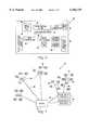
- FIG. 1is a system for viewing live images, in real-time, from multiple remote locations by communicating the images over wireless and wired networks and by accessing the images from multiple user computers connected to the networks, according to embodiments of the invention.
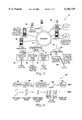
- FIG. 2is a camera element for acquiring the images for the system of FIG. 1 and for communicating the images over wireless networks, according to embodiments of the invention.
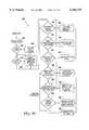
- FIG. 3is a processor card of the camera element of FIG. 2, according to embodiments of the invention.
- FIG. 4is a wireless network of the system of FIG. 1, over which the camera elements communicate the images, according to embodiments of the invention.
- FIG. 5is a central office video management system of the system of FIG. 1, which selectively receives, manages, and distributes the images received from the camera elements to the multiple user computers, according to embodiments of the invention.
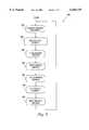
- FIG. 6is a method of operation of an image acquisition cycle of the camera element of FIG. 2, according to embodiments of the invention.
- FIG. 7is a simplified flow diagram of a method of operation of the camera element of FIG. 2, according to embodiments of the invention.
- FIG. 8is a flow diagram of a broadcast mode sequence of the camera element of FIG. 2, according to embodiments of the invention.
- FIG. 9is a flow diagram of a demand-mode sequence of the camera element of FIG. 2, according to embodiments of the invention.
- FIG. 10is a flow diagram of an event-driven mode sequence of the camera element of FIG. 2, according to embodiments of the invention.
- FIG. 11is a flow diagram of a trigger-driven mode sequence of the camera element of FIG. 2, according to embodiments of the invention.
- FIG. 12is a simplified illustration of an "around" sub-mode of the camera element of FIG. 2, according to embodiments of the invention.
- FIG. 13is a simplified illustration of a "before" sub-mode of the camera element of FIG. 2, according to embodiments of the invention.
- FIG. 14is a simplified illustration of an "after" sub-mode of the camera element of FIG. 2, according to embodiments of the invention.
- FIG. 15is a flow diagram of an initialization method of the central office video management system of FIG. 1, according to embodiments of the invention.
- FIG. 16is a method of normal operations of the Business Manager main processing loop of the central office video managemnent system of the system of FIG. 1, according to embodiments of the invention.
- FIG. 17is a method of operations of the Business Manager when a CommLink Manager of the central office video management system of the system of FIG. 1 indicates that a new camera element is available to the system of FIG. 1, according to embodiments of the invention.
- FIG. 18is a method of operations of the Business Manager when a service level change is requested from a user computer of the system of FIG. 1, according to embodiments of the invention.
- FIG. 19is a method of registering a new customer or display web-site for the system of FIG. 1, according to embodiments of the invention.
- FIG. 20is a method of operation of a CommLink Manager of the system of FIG. 1, according to embodiments of the invention.
- FIG. 21is an illustration of primary data structures employed by an Image Processing Manager of the system of FIG. 1, according to embodiments of the invention.
- FIG. 22is a method of operation of the Image Processing Manager of the system of FIG. 1, according to embodiments of the invention.
- FIG. 23is a method of operation of a sub-process of adding new camera elements of the Image Processing Manager of the system of FIG. 1, according to embodiments of the invention.
- FIG. 24is a method of operation of a sub-process of changing a service level for the Image Processing Manager of the system of FIG. 1, according to embodiments of the invention.
- FIG. 25is a method of initialization of a Web Server Communications Manager of the system of FIG. 1, according to embodiments of the invention.
- FIG. 26is an illustration of an outbound image queue of the Web Server Communications Manager of the system of FIG. 1, according to embodiments of the invention.
- FIG. 27is a simplified illustration of operations of the Web Server Communications Manager of the system of FIG. 1, according to embodiments of the invention.
- FIG. 28is a flow diagram of a method of normal operations of the Web Server Communications Manager of the system of FIG. 1, according to embodiments of the invention.
- FIG. 29is a flow diagram of a process maintenance routine of the Web Server Communications Manager of the system of FIG. 1, according to embodiments of the invention.
- FIG. 30is an illustration of data structures and their relationship, as used by the Web Server Communications Manager of the system of FIG. 1, according to embodiments of the invention.
- FIG. 31is a simplified illustration of a web site of the system of FIG. 1, according to embodiments of the invention.
- FIG. 32is a flow diagram of an initialization process of the web site of FIG. 31, according to embodiments of the invention.
- a remote viewing system 10includes camera devices 12, a wireless network 14, a central office video management system (COVMS) 16, a World Wide Web server 18, a network 20, and a computer 22.
- the camera devices 12are operatively connected via radio frequency with the wireless network 14 for communications therebetween.
- the wireless network 14is connected by communications wire with the COVMS 16.
- the COVMS 16is connected by communications wire with the World Wide Web server 18.
- the World Wide Web server 18is connected by communications wire with the network 20, such as the Internet.
- the computer 22is operatively connected with the network 20 for communications between the computer 22 and the network 20.
- the computer 22is equipped with appropriate software, for example, a web browser, for accessing information available on the network 20.
- the camera device 12includes a camera 24, a video digitizer 26, a processor card 28, a remote communications link module 30, an antenna 32, and a power supply 34.
- the camera 24is connected to the power supply 34 and the video digitizer 26.
- the video digitizer 26is connected to the processor card 28.
- the processor card 28is also connected to the power supply 34.
- the remote communications link module 30is connected to the processor card 28 and the power supply 34.
- the remote communications link module 30is also connected to an antenna 32.
- the camera 24is a CCD CCTV camera element, for example, a one-half inch camera element, and a camera lens.
- a camera enclosureholds the camera element, the camera lens, and the power supply 34.
- the camera element and the camera lensare conventional components known to those skilled in the art.
- the camera enclosurealso contains the video digitizer 26, the processor card 28, and the remote communications link module 30.
- a power cordmay also connect the power supply of the camera enclosure to the components.
- the camera enclosuremay also be equipped with a separate power cord suitable for standard 120V, 60 HZ, AC electric outlets.
- the antenna 32is connected to the camera enclosure.
- the camera 24is connected to the video digitizer 26.
- the video digitizer 26is a digital video frame grabber element.
- a standard coaxial cable with BNC connectorsconnects the camera 24 to the video digitizer 26.
- the video digitizer 26is a conventional element known to those skilled in the art.
- the processor card 28connects to the video digitizer 26 by a PC-104 standard bus header connector. Power is supplied to the video digitizer 26 by the processor card 28 from the power supply 34.
- the remote communications link module 30is connected to the processor card 28 by an RS-232 link to a standard UART chip of the processor card 28 (as hereinafter more particularly described).
- the remote communications link module 30is a radio frequency (RF) radio capable of communicating with the wireless network 14 (shown in FIG. 1).
- RFradio frequency
- the remote communications link module 30is a CDPD modem.
- the antenna 32connects with the remote communications link module 30.
- the antenna 32is an external omni-directional antenna.
- the antenna 32provides RF communications with the wireless network 14 (shown in FIG. 1).
- the power supply 34is a standard source of power, such as a conventional 120V supply or a battery that, in any event, generates about ⁇ 5 volts and also generates about ⁇ 12 volts.
- the power supply 34is connected with the camera 24, the processor card 28, and the remote communications link 30 and provides power thereto. As previously mentioned, power is supplied to the video digitizer 26 from the power supply 34 via connection through the processor card 28.
- the processor card 28includes a 486-class microprocessor 40 operating at 100-120 MHZ.
- the microprocessor 40is connected to an EEPROM 42, for example, 2-4 MB of memory, for code storage.
- the microprocessor 40is also connected to DRAM memory, for example, 8 MB of memory, for program execution.
- a UART chip 46for example, a model 16550A UART, together with dual row header strips 48, are provided to implement a serial port for connection to the remote communications link module 30 (shown in FIG. 2).
- the processor card 28also includes a PC-104 bus connector 50 for connecting the processor card 28 with the video digitizer 26 via a PC-104 bus.
- the processor card 28includes conventional elements of a bus controller 54, cache memory 56, and glue logic 58.
- the processor card 28is conventional and known to those skilled in the art.
- the wireless network 14is shown connected to the central office video management system (COVMS) 16.
- the wireless network 14includes dedicated cell sites 60, third-party cell sites 62, or both.
- each cell site 60 or 62is conventional and includes a base station with antenna connected to the COVMS 16, in the case of the dedicated cell sites 60, and to commercial third-party provider networks 64, in the case of the cell sites 62, by frame relay circuits 66 and 68, respectively.
- the connectionscould be other conventional connections, such as T1 line, ATM, or other.
- the base station antenna of each of the cell sites 60 and 62is conventionally elevated, for example, by mounting on top of buildings, and receives incoming data, such as image data, from the camera elements 12 corresponding to the particular cell.
- the camera elements 12are equipped with RF radios compatible with the commercial provider network 64.
- the cell sites 62likewise have mounted antennas and receive incoming data from the camera elements 12.
- the cell sites 60are connected directly with the COVMS 16 by the relay circuits 66.
- the cell sites 62are connected to the respective commercial provider networks 64.
- the commercial provider networks 64are connected by dedicated frame relay circuits 70 to the COVMS 16.
- the COVMSconnects to the wireless network 14 (shown in FIGS. 1 and 4) by one or more frame relay access (FRAD) devices 70.
- the FRAD devices 70each connect with a single one of the cell sites 60, the commercial wireless providers 64, or separate dedicated networks. As previously mentioned, each cell site 60 and commercial wireless provider 64 is connected with the COVMS 16 via a frame relay circuit 66 or 70, respectively.
- the frame relay circuit 66 or 70interfaces to the FRAD device 70.
- the FRAD device 70may, for example, be FRAD device model F822I available from FastCom of Sterling, Va.
- the FRAD devices 70are connected to a fiber distributed data interface (FDDI) bridge by a 10 BaseT fast ethernet connection 74.
- FDDIfiber distributed data interface
- a fiber distributed data interface (FDDI) ring 76is connected to the FDDI bridge 72.
- the FDDI ring 76interconnects one or more host computers 78.
- Single ones of the host computers 78service various numbers of the cell sites 60 or 62.
- Each host computer 78is, for example, a dual Pentium Pro 180 MHZ system with 128-256 MB of memory running the FreeBSD operating system.
- the host computers 78each include disk subsystems, for example, SCSI disks.
- the capacity of single ones of the host computers 78will depend on the number of available connection ports and the particular wireless network 14 to which connected.
- the host computers 78are particularly sensitive to the available memory and network performance, however, computational horsepower of the computer 78 is of less concern.
- the COVMS 16includes one or more dynamic name servers 80, file servers 82, and administrative workstations (not shown).
- the dynamic name server 80is a PC-based systems running FreeBDS.
- the dynamic name server 80is a Pentium 200 MHZ computer with 64 MB of memory.
- the file servers 82include SCSI disk subsystems and are, for example, Pentium Pro 150 MHZ computers with 128 MB of memory.
- the file servers 82include high end SCSI adapters attached to 2-8 Gbyte of the SCSI disks.
- the file servers 82run the Linux operating system.
- the file servers 82may choose to use RAID arrays if the scale of the COVMS 16 warrants such use. Additionally, the file servers 82 may use DAT tape and WORM drives to perform periodic system backups.
- the administrative workstations(not shown) are connected with the system 16 and allow system administrators and technicians to monitor network status and make adjustments.
- the administrative workstationsare, for example, Pentium 200 MHZ systems with 32 MB of memory.
- the administrative workstationsinclude high end graphics display.
- the Linux, FreeBSD, or Windows NT operating systemsare run on the administrative workstations.
- the graphics components of the administrative workstationsare, for example, 21 inch 0.26 dpi RGB color monitors and display adapter cards, such as the Matrox Millennium display adapters with 8 MB of WRAM memory.
- High resolution display capabilitiesare necessary for the administrative work stations because the workstations must periodically be employed to evaluate image quality of the system 10 (shown in FIG. 1).
- the FDDI ring 76 of the COVMS system 16is connected by fiber distributed data interface with a suitable router, such as a Cisco 7000 router 84.
- a suitable routersuch as a Cisco 7000 router 84.
- the COVMS system 16interfaces to a wide area network (WAN) link, for example, by a T3 digital service unit/channel service unit (DSU/CSU), such as the Digital Link DL3200 T3 SMDS/ATM DSU available from Digital Link Corporation of Sunnyvale, Calif.
- the Cisco 7000 routerhas a protocol interface module that allows it to be directly connected to the FDDI ring 76.
- the DSUprovides channelization up to the full 45 Mbps bandwidth of the T3 WAN link.
- the router 84interfaces next to the DSU by a high speed serial interface (HSSI) connection.
- HSSIhigh speed serial interface
- a web site connectionis made to the DSU/CSU 86.
- the web site connection 88may be a T1 or T3 connection.
- a tiered T3 connectionis required for the very high band width of the circuit (up to 45 Mbps).
- the T1 connectionmay be suitable for the system 16 when small.
- the World Wide Web server 18is any of a variety of computers capable of serving as a server computer connected to the Internet or some other network 20. Information available from the World Wide Web server 18 is accessed by a web-enabled computer 22.
- the web-enabled computer 22may be a personal computer, network computer, or other device that is connected with the network 20.
- the computer 22is capable of accessing information available over the network 20 from the World Wide Web server 18, for example, by operating a web browser software, a dedicated image display device or some other suitable display mechanism.
- the World Wide Web server 18, the network 20, and the computer 22, together with their interconnection,are conventional and known to those skilled in the art.
- each of the cameras 12acquires images at the site at which located and converts those images to digital data information.
- the digital datais processed, compressed, and then transmitted over the wireless network 14 to the COVMS 16.
- the cameras 12use the TCP/IP protocol suite for communications over the wireless communications links of the wireless network 14.
- Each of the cameras 12is configured, prior to being deployed at a location, with an ID record that includes geographical information about the location of the camera 12, the camera hardware and system settings of the camera 12, an IP address, and a primary and secondary COVMS 16 for connection upon startup. If the camera 12 has powered up and acquired network connections, the camera 12 begins to periodically send image data to the COVMS 16 and may also accept various control commands from the COVMS 16.
- the cameras 12communicate with the COVMS 16 over the wireless network 14.
- the wireless network 14may be cell sites 60 which communicate directly with the COVMS 16 dedicated for use with the cameras 12 or commercial wireless data communications providers 64 which communicate with the COVMS 16 or some other direct connection of a third party to the COVMS 26.
- the base station antenna of each of the cell sites 60receives image data from the camera 12 using a DDCIP protocol. That protocol facilitates TCP/IP networking over spread spectrum radio links.
- the DDCIP protocolfollows the OSI network model.
- the ARP protocol in the Ethernet environmentis replaced with a static mapping mechanism specific to the radio frequency environment, e.g., the ARP protocol is replaced with a static routing table and routing according to the table.
- the DDCIP protocolaccommodates routing from the radio frequency onto the wireline protocol.
- the protocoluses primarily UDP for sending data and implements its own data validity and error checker.
- the protocol's method of compensating for errorsis to re-send only those pieces of data within a transmitted file that was received in error.
- the cameras 12 in communication with the commercial wireless data communications providers network 64communicates image data over the providers network 64.
- the providers network 64connects to a frame relay circuit 70 that connects the COVMS 16 and the providers network 64.
- Other dedicated connections with the COVMS 16(not shown in the Figures) are directly connected to the COVMS 16 and communicate with the COVMS 16 in similar fashion.
- the COVMS 16processes the images and then transfers them to the storage facility for archive, to the World Wide Web 18, and to dedicated connections with the COVMS 16 of certain users, if any.
- the COVMS 16acts substantially as a switch to direct the output of multiple ones of the cameras 12 in operation at any time to multiple users accessing the images.
- the COVMS 16also performs image processing operations on the images.
- the COVMS 16receives each image, as compressed and transmitted by the cameras 12, and decodes the image data.
- the COVMS 16then decompresses the images and provides post-processing operations to compensate for lighting conditions and other factors.
- the COVMS 16compresses the image information according to industry-standard image file formats, for example, JPEG formats, and passes the information to the World Wide Web server 18.
- Other operationsmay take place at the COVMS 16, such as, for example, specialty image processing like object detection, object count, event recognition, and others.
- the image informationis made available in the industry standard format for access over the network 20 by the computer 22.
- the computer 22may access the image information over the Internet using the World Wide Web and standard web browser software. Alternately, images may be accessed directly over dedicated networks.
- each of the camera elements 12operates according to a particular image acquisition cycle, identified in the Figure as process 100.
- the camera of the camera element 12acquires raw image data.
- the image datais digital data.
- the digital imageis captured by the CCD imaging element of the camera 24.
- Image capture ratesmay vary according to desired operations, particularly, the camera 24 has four operating modes and three sub-modes.
- the four operating modesare "broadcast", “demand-driven”, “trigger-driven”, and “event-driven”.
- the three sub-modesare "around", "before", and "after”.
- the particular operating modedetermines what is the actuating event that causes an image to be transmitted by the camera element 12 over the wireless network 14.
- the particular sub-modedetermines how many images are transmitted in the instant, and whether the images are captured before, after, or around the actuating event.
- the set of images transmitted as a result of an actuating eventis referred to as the "image payload”.
- the sub-modes and respective sub-mode parametersadditionally determine the size of the image payload in any instance. Notwithstanding the particular operating mode and sub-mode in any case, the digital image data is passed by the camera 24 to the video digitizer 26.
- the digital image datamay be maintained in the video digitizer 26, for example, in the frame store thereof, or brought into main memory of the processor card 28 for processing.
- a step 104the digital image data is processed.
- the particular processingdepends upon the camera element 12 and the particular programming and instructions received from the COVMS 16.
- the processing step 104may include various operations ranging from color channel separations, to complex filtering, to motion detection operation, and others. If the camera element 12 is in the event-driven mode (later discussed in more detail), the image event may at this time be registered. Registry of the event results in transmission of the image payload, once the necessary images have been captured by the camera element 12.
- the processed image datais compressed for transmission over the wireless network 14.
- the processor card 28compresses the image according to the assigned codec for the particular camera 24.
- the COVMS 16can upload different codec configurations for the camera element 12 for different applications or changing image conditions.
- the codeccan be any of a variety of possibilities, for example, wavelet based compression algorithms, DCT based compression algorithms, JPEG, MPEG, or others. In any event, the codec compresses the image data to suitable size for rapid transmission over the wireless network 14.
- the compressed imageis placed in one of two transmit output queues.
- the two output queuesare a "before" output queue and an "after” output queue.
- the before output queueis used for images acquired before the actuating event
- the after output queueis used for images acquired after the actuating event before the image payload is transmitted.
- the image payloadconsists of the contents of the before and after queues at the transmit time, as determined by the mode parameters (as more particularly hereinafter discussed). Whether or not particular image data is transmitted to the COVMS 16 depends on the sub-mode of the camera element 12 and the image's position in the before and after queues.
- the compressed image in the queuesis transmitted over the wireless network 14.
- the actuating event that causes the camera element 12 to transmit the image payloaddepends upon the operating mode.
- the actuating eventcan be either an update timer or clock (i.e., broadcast mode), an incoming image request from the COVMS 16 (i.e., demand-driven mode), an external triggering event (i.e., trigger-driven mode), or an event detected by the camera element 12 (i.e., event-driven mode).
- the sub-modei.e., either around, before, or after determines how many images shall make up the image payload and from which queues those images come.
- the transmit processconverts the image payload into a serial bit stream and then transits the stream over the wireless network 14 using the remote communications link module 30 and the antenna 32.
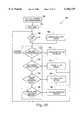
- the camera element 12proceeds through a process identified by 120.
- the process 120is, in effect, that just described with reference to FIG. 6, with repetition.
- the process 120thus, includes the steps 102, 104, 106, 108, and 110 as described. Additionally, however, the process 120 includes a return path 122. Over the return path 122, a change of mode 124 may be indicated and a determination of whether there has been expiration of an update interval in a step 126 is made prior to returning to the step 102.
- the process 120is followed by the camera element 12 in each of the four modes, however, the different modes alter the order and frequency in which the steps 102, 104, 106, 108, 110, 122, 124, and 126 occur.
- the camera element 12automatically sends the image payload to the COVMS 16 at the end of each update interval.
- the update interval programmed into the camera element 12 by the COVMS 16is used to set a system timer to trigger transmission at the end of each interval.
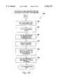
- the broadcast mode sequence 130proceeds with a process server command step 132. Thereafter, the sequence 130 proceeds through a delay step 134, a run acquire service step 136, a run process service step 138, and a run compress service step 140.
- steps 132, 134, 136, 138 and 140are put in the before queue, which is a FIFO buffer, in a step 142.
- the run transmit service step 144occurs and the sequence 130 returns to commencement.
- the sequence 130is repeated every update interval period.
- the effect of the updateis that the camera element 12 sends a new image for receipt by the wireless network 14 once every update. In broadcast mode, the image payload is always equivalent to one image.
- the demand-mode sequence 150 of the camera element 12causes the camera element 12 to act, in effect, like a server, sending the image payload to the COVMS 16 only when requested by the COVMS 16.
- the camera element 12listens for an image request command on the port of the COVMS 16 for the camera element 12. When such a request command is detected, the camera element 12 transmits the image payload.
- the sequence 150proceeds first by a process server command step 152.
- the camera element 12then runs an image acquisition cycle of a delay step 154, a run acquire service step 156, a run process service step 158, and a run compress service step 160, and the result is placed in the before queue in step 162.
- the before queueis thereafter updated in a step 163.
- the sequence 150then checks for receipt by the camera element 12 of an image request in step 164. If no image request has been received at this step 164, the sequence 150 returns in step 166 to again commence the image acquisition cycle. If, however, an image request has been received by the step 164, the camera element 12 proceeds with a run transmit service step 168 in which the image payload is transmitted by the camera element 12. Thereafter, the before queue is cleared in a step 170 and the sequence 150 returns to commencement. It is of note that the demand-driven mode always transmits some number of images acquired before the actuating event actually occurs.
- an event-driven mode sequence 180triggers transmission of the image payload by the camera element 12 upon the occurrence of some event recognized by the camera element 12.
- the camera element 12repeatedly runs the image acquisition cycle, but without the transmission step 144 at each cycle as in the broadcast mode sequence 130 (shown in FIG. 8).
- the event upon which transmission is to occuris detected by an image processing application running at the camera element 12.
- the image processing applicationexamines each acquired image for the event.
- the camera element 12begins transmitting the image payload after the camera element 12 has captured all required images, as determined by the sub-mode (as later discussed in more detail).
- the event driven mode sequence 180proceeds with a process server commands step 182.
- the sequence 180then continues through a delay step 184, a run acquire service step 186, and a run event detect service step 188.
- a step 190it is determined whether the event is then detected. If the event is not then detected, the sequence 180 continues through a flip input p--p switch step 192. After the step 192, a step 194 determines whether the sub-mode is "after”. If not "after”, then the sequence 180 continues to a run process service step 196 and a run compress service step 198. The result is put in the before queue in a step 200, and the before queue is updated in a step 202. Thereafter, a determination is made in a step 204 whether the before queue is full. If the before queue is full, the sequence 180 returns to commencement. If the before queue is not full, then the sequence 180 returns to the delay step 184.
- a counteris set to 0 in a step 206.
- the sequence 180then proceeds to a run process service step 208 and a run compress service step 210.
- the counteris then incremented in a step 212.
- the result of the run compress service step 210is put in the after queue in a step 214.
- the after queueis updated.
- a determinationis then made in a step 218 whether the sub-mode is "before”. If it is "before", then the sequence 180 proceeds to a run transmit service step 220, followed by a clear queues step 222 and return to commencement.
- a test of the counteris made to determine if it equals a particular number of format frames plus 1. If yes, then the sequence 180 continues to the run transmit service step 220 and on. If the counter is not equal to the particular number of format frames plus 1, then the sequence 180 passes to a delay step 226 and a run acquire service step 228. After the run acquire service step 228, the sequence 180 proceeds to the run process service step 208 and continues thereafter. It is notable that, in the event-driven mode sequence 180, each time the event is detected the camera element 12 transmits the image payload.
- a trigger-driven mode sequence 230includes transmission of the image payload controlled by an external triggering device. Operation of the sequence 230 is similar to the event-driven mode sequence 180 except that the triggering device in the trigger-driven mode sequence 230 may be an external switch, road sensor, or other particular external triggering event.
- the camera element 12transmits the image payload after the trigger event is detected and after the camera element 12 has captured all required images, as dictated by the sub-mode.
- the sequence 230commences with a process server command step 232.
- a mode determination step 234assesses whether the sub-mode is "after".
- sequence 230proceeds through an image acquisition cycle including a delay step 236, a run acquire service step 238, a run process service step 240, and a run compress service step 242. Results of the cycle are put in the before queue in a step 244, which is updated in a step 246.
- a step 248follows in which it is determined whether the trigger event has occurred. If the trigger event has not occurred, the sequence 230 returns to commencement. If the trigger event has occurred and is detected in the step 248, again the sub-mode is assessed in a step 250, this time for "before" sub-mode. If the submode determined in the step 250 is "before”, then the sequence 230 proceeds to a run transmit service step 252 followed by a clear queues step 254, with return to commencement of the sequence 230. If the mode assessment step 250 determines that the sub-mode is not "before”, then the sequence 230 proceeds to a set counter to zero step 256, followed by a delay step 258.
- the sequence 230then proceeds through a run acquire service step 260, a run process service step 262, and a run compress service step 264.
- the counteris incremented in a step 266.
- the result of the run compress service step 264is placed in the after queue in a step 268, and the queue is updated in the step 270.
- the sub-mode of the camera element 12dictates which images and how many of those images are transmitted in each image payload.
- the sub-mode "around"includes the capture and transmission by the camera element 12 of some number of images both before and after an event that actuates the transmission of the images.
- the number of frames captured on either side of the eventis programmable, and is preferably a small number due to memory constraints.
- the sub-modehas four parameters: the number of the before frames captured (N), the number of after frames captured (J), the BDelVal, and the ADelVal.
- the BdelVal and ADelValcontrol how much time the camera element 12 allows between captured frames. The value is expressed in milliseconds.
- the camera element 12captures and transmits some number of images before the event that actuates the transmission of the images in the "before" sub-mode.
- the number of frames capturedis programmable, but is preferably a small number because of memory constraints.
- the "before” sub-modehas two parameters: the number of "before” frames to capture (N) and the BDelVal value.
- the BDelVal valuecontrols the amount of time allowed between captured frames and is expressed in milliseconds. Compressed images acquired before the actuating event are placed in the "before" queue.
- the camera element 12captures and transmits some number of images after the event that actuates transmission in the "after" sub-mode.
- the number of frames capturedis programmable, and is preferably a small number, for example, one frame.
- the "after" sub-modehas two parameters: the number of "after" frames to capture (J) and the ADelVal value.
- the ADelValdictates how much time the camera element 12 allows between captured frames, in milliseconds.
- the operating modeis "broadcast”
- the BDelVal and the ADelVal parametersare the same.
- Image payloads acquired after the actuating eventare placed in the after queue.
- the camera element 12begins transmitting the image payload.
- the COVMS 16(shown in FIG. 1) receives and decodes the images from the wireless network 14 from all cell cites 60 and 62 and related camera elements 12. The COVMS 16 then sends the resulting images to the server 18 so that the computers 22 can access the images over the network 20.
- the operationsare the Business Manager, the CommLink Manager, the Image Processing Manager, and the Web Server Communication Manager.
- the Business Manageris the fundamental operation of the COVMS 16 that supports all operations.
- the CommLink Manager, the Image Processing Manager, and the Web Server Communications Managerare, therefore, referred to collectively herein as the "Sub-processes" (although referred to by the term “Sub-processes,” these processes should not be confused with further sub-processes of the Image Processing Manager, specifically, which are distinct sub-operations within the particular Image Processing Manager Sub-process).
- the methods of the operations of the Business Manager and the Sub-processesare as follows:
- the Business Managerperforms several operations.
- the Business Managerinitializes the COVMS 16, starts-up the Sub-processes, monitors the COVMS 16 performance, performs central data base maintenance, manages communications between and among the Sub-processes and the Business Manager, manages communications between the COVMS 16 and other COVMS's, if more than one, and manages customer connections and web site connections to the COVMS 16.
- the COVMS 16upon booting the COVMS 16, the COVMS 16 initially proceeds through a method 300 of initialization of the system 10.
- the method 300includes system verification and resource allocation and Sub-process start-up functions.
- the method 300proceeds with a step 302 in which the Business Manager checks and matches hardware and software release versions of the system 10 in order to ensure that all are properly compatible and supported.
- the Business Managermeasures memory and processing capabilities of the system 10 and, based on the measurements, operating parameters are set by the Business Manager that determine the number of the camera elements 12 the COVMS 16 can support. Resources of the network of the COVMS 16 are tested in a step 306.
- the COVMS 16determines whether there are one or more of the host computers 78 of the COVMS 16. If there are more than one of the host computers 78 in the COVMS 16, then each is assigned an ordinal ID from one of the host computers 78 arbitrarily designated as the master of the host computers 78.
- the Business Manageropens a master database (the "Master Camera Element Database”) for the camera elements 12 for random access thereto and creates a table (the "Active Camera Element Table") of the camera elements 12 that are active in the system 10 in the COVMS 16 memory.
- the Business Managernext starts-up the CommLink Manager in a step 310.
- the Business Managerprovides to the CommLink Manager various operating parameters, including the number of camera element 12 link processes to create, memory limitations, and pointer to the Master Camera Element Database and the Active Camera Element Table. Communications with the CommLink Manager in the step 310 are symbolized in FIG. 15 by the arrows 310'.
- the CommLink Manager operationsare discussed in Section (2), below.
- a step 312the Business Manager starts-up the Image Processing Manager.
- Various operating parametersare passed between the Business Manager and the Image Processing Manager in the step 312, which are symbolized in FIG. 15 by the arrows 312'.
- the Image Processing Manager operationis discussed in Section (3), below.
- a step 314the Business Manager looks for any pending connection requests from any of the computers 22.
- the pending connection requestsif any, are available to the Business Manager over the network 20, either through a web site of the World Wide Web server 18 for computers 22 that communicate over the Internet, through a direct connection to the network 20 for computers 22 that may have such direct connection, or from both, as the case may be for multiple computers 22.
- the Business Managerestablishes links corresponding to the pending connection requests in the step 314. Information about each of the links is placed in a table (the "Active Output Link Table") of active output links for the camera elements 12.
- the Business Managermaintains the Active Output Link Table.
- a step 316the Business Manager starts-up the Web Server Communications Manager. Operations of the Web Server Communications Manager are discussed in Section (4), below.
- the Web Server Communications Managermakes several requests of the Business Manager through inter-task messaging, symbolized in FIG. 15 by the arrows 318'.
- the Business Managerfills an Image Output Mapping Table created by the Web Server Communications Manager in the step 318.
- a step 320the Business Manager begins a main processing loop of normal operations.
- a method of the main processing loop of normal operations of the Business Manageris indicated generally by the number 320 (i.e., the method is the step 320 of FIG. 15).
- the Business Manageracts essentially as a command server, processing request messages sent to the Business Manager from resources of the system 10 and from the web site of the World Wide Web server 18 and from the computers 22.
- the method 320proceeds with a step 322 of starting a timer.
- the Business Managercreates and maintains a table of image output queues for the Web Server Communications Manager. In this respect, the Business Manager creates the queues, hands off pointers to the queues to the Web Server Communications Manager, and monitors status of the queues. Several statistics monitored for status include the queue size (i.e., the number of images waiting in the queues), the average queuing latency, the average time to live status of images in the queues, and dwell time ratios among the queues. The Business Manager tracks these statistics and adjusts variable parameters of operation of the system 10 (e.g., adds more servers, adds more bandwidth, adds more memory, and so forth) to keep the statistics within desired values.
- step 328determines whether 10 minutes have passed since the start of the timer of the step 322. If 10 minutes have not passed, the method 320 proceeds to a step 330 of tabulating commercial wireless network usage by the system 10.
- the Business Managerperiodically monitors usage of commercial wireless networks by the system 10 in efforts to optimize for minimal costs of such usage. For example, the Business Manager may in certain conditions change operating mode or service level or shut down a particular one of the camera elements 12 if costs exceed preprogrammed thresholds. The Business Manager also alerts administrators if costs are excessive for any particular ones of the camera elements 12 or in the aggregate. The information is useable by administrators to determine where and whether to replace a third-party cell site 62 with a dedicated cell site 60, or to take other actions. Once 10 minutes have passed, the method 320 continues through command server steps.
- a step 342 of determining whether a change of service level is to be effectedfollows the step 338 if a new one of the computers 22 is not then registered. If a change service level request is received at the step 342, a step 344 of changing the service level follows. After the step 344, the method 320 returns to the step 322 in the step 336. If no change service level request is received at the step 342, a step 346 determines whether a new broadcast message is then received from one of the camera elements 12. If a new broadcast message is received at the step 346, the broadcast message is processed in a step 348. The method 320 thereafter returns to the step 322 in the step 336.
- a step 350detects whether a message is then received to fill an active camera element list maintained at the web site of the World Wide Web server 18. If the message is then received, a step 352 sends the active camera element list to the web site and the method 320 returns to the step 322 in the step 336. If the message is not received, a step 354 detects whether a report system statistics message has been received. If the message is received at the step 354, the system statistics are reported to the system administrator in a step 356. Following the step 356 or if the report system statistics message is not then received, the method 320 returns to the step 322 in the step 336.
- the foregoing server command stepsare exemplary of those performed by the Business Manager. Additional or alternative steps may be performed, as those skilled in the art will understand and appreciate.
- three critical tasks for operation of the system 10are the steps 338 and 340 of detecting requests for and registering new computers 22, the steps 346 and 348 of detecting receipt of broadcasts from the camera elements 12 and processing those broadcasts, and the steps 342 and 344 of detecting change of service level requests and responding thereto. The following describes each of the tasks in greater detail.
- the Business Managerwhen the CommLink Manager announces that a new one of the camera elements 12 is available to the system 10, the Business Manager responds by the method 348 of assigning the image data to an output queue and insuring that the images are sent to the right ones of the computers 22.
- the Business Managercreates a new record for a new one of the camera elements 12 in the Image Output Mapping Table.
- the Business Managerthen gets a pointer to the first record in the Active Output Link Table in a step 404.
- the method 400proceeds to a step 418 of marking the active link output pointer structure as disabled. Thereafter, the pointer is incremented in the step 408 to get the next record. In a step 420, a query is made whether the last record has been passed. If not, the method 400 returns to the step 406 of determining whether there is any match such that the camera element 12 is permitted.
- the method 400proceeds to a step 422 of determining whether at least one output destination, that is, at least one of the computers 22, has been enabled. If there is at least one output destination that has been enabled at the step 422, a step 424 provides an output queue assignment, and updates the COVMS 16 tables of the camera elements 12 that are active with the particular output queue assignment. If there is not at least one output destination that is enabled at the step 422 or if the step 424 is completed, a step 426 sends a message to each delivery site, i.e., each of the computers 22, to inform them of the availability of the new one of the camera elements 12.
- the Business Managerproceeds with the method 344.
- the method 344checks the request against the capabilities of the relevant one of the camera elements 12 as given in the Master Camera Element Database. If the check is not satisfactory, a failure message is returned to the computer 22 that made the request. If the check is satisfactory, the Business Manager passes the request on to the Image Processing Manager for processing. At a later point, the Image Processing Manager returns a message to the Business Manager advising it of success or failure of the prior requests. This message is relayed to the computer 22.
- a comparisonis made of the request parameters against the record for the camera element 12 in the Master Camera Element Database.
- a step 452follows in which a determination is made whether the camera element 12 is capable of satisfying the request. If the camera element 12 is not so capable, a step 454 sends a failure message to the computer 22 making the request. If the camera element 12 is so capable, a step 456 sends a message to the Image Processing Manager. The Image Processing Manager then takes over as later discussed in Section (3), below.
- the method 340 of registering a new customeri.e., a new one of the computers 22 that is allowed access to images of the camera elements 12, proceeds with a step 470 of receiving a customer or web site connection request on a public port.
- the source of the requestis authenticated.
- a step 474follows in which a determination is made whether the source is, in fact, authenticated. If there is not authentication in the step 474, a log failure and alert to the administrator occurs in a step 476.
- the method 340returns to the method 320 (shown in FIG. 16).
- control, command, and data TCP/IP connections with the sourceare created in a step 476.
- an updateis made of the Active Output Link Table with the new source.
- a step 480initiates logging of transactions by the new source in a record of the Active Output Link Table.
- a step 482updates the image output mapping table to include the new source.
- the Business Manageralso monitors overall performance of the system 10 and performs adjustments to operations of the system 10 to make it run more efficiently.
- the Business Managerfurther maintains the central data base that contains specifics of the system 10. Modifications to the system 10 are notified by the process responsible to the Business Manager to make the update.
- the CommLink Managerhandles all communications between the camera elements 12 and the COVMS 16. In general, each communication between any one of the camera elements 12 and the COVMS 16 is assigned an identification (ID). The ID is used by all the other processes within the system 10.
- the CommLink Managermaps each ID into an IP address before processing communication requests related to the particular communication. In processing communication requests, the CommLink Manager receives incoming communication requests from the camera elements 12, authenticates the requests, and then assigns necessary resources of the system 10 to process the image data from the camera elements 12.
- a process 500 of the CommLink Managerbegins with the COVMS 16 listening for the camera elements 12 sending existent broadcasts in a step 502.
- the COVMS 16tests whether an incoming broadcast is detected. If no such broadcast is detected, the process 500 returns to the step 502. If an incoming broadcast is detected, that broadcast includes the serial ID for the camera 12.
- the camera element 12is authenticated according to the ID and is assigned an IP address in a step 512.
- a particular port of the COVMS 16is assigned for use by the camera element 12 in communications with the COVMS 16.
- the COVMS 16then sends a connection granted message to the camera element 12 via the particular port and the specific identifier.
- the COVMS 16in a step 522, then sends a transmit request to the camera element 12 for the particular configuration record applicable to the camera element 12.
- a determinationis made in a step 524 whether the record is received by the COVMS 16 from the camera element 12. If not received, then the database record for the camera element 12 is deleted from the active table in a step 526.
- the particular port of the COVMS 16 assigned to the camera element 12is then released in a step 528, and the process 500 returns to the step 502.
- the COVMS 16 in a step 526assesses whether the record is suitable. If suitable, an update of the active table is made if necessary, in a step 528. If the record is not suitable, a command is transmitted to change parameters in a step 530. After the step 528 or the step 530, as the case may be, the camera element is linked to the COVMS 16 in a step 532. In a step 534, the COVMS 16 notifies each of its components that the camera element 12 is linked with the system 10. A link message is sent to all components of the system. When the Image Processing Manager receives the link message, it looks for the link and sets up a queue for input. When the Business Manager receives the link message, it sets up a queue for output. The process 500 then returns to the step 502.
- the Image Processing Managerhandles the image processing functions of the COVMS 16.
- the Image Processing Managerhas sub-processes that handle the respective image streams from each camera element 12.
- the CommLink Managerdirects the communication link to dump received encoded image data to the designated input queue.
- the CommLink Managerthen sends a message to the Image Processing Manager that a particular sub-process must be set-up by the Image Processing Manager to retrieve the data from the queue and process it.
- the Image Processing Managerthen sends a message to the Business Manager to set-up the separate, particular receiving output queue for the image stream.
- the Image Processing Manageruses two primary data structures, and several secondary data structures to keep track of the sub-processes and input queues that are active in the system 10.
- the relationship of the various structuresare given in FIG. 21.
- the Image Processing Manageruses an Active Processor List Table to maintain a list of active sub-processes running in the system 10. Each active sub-process has an entry in the table that points to a processor record (processor -- que -- rec), where non-active list entries contain the null pointer value.
- Each sub-process recordcontains information about the type of sub-process, a pointer to an input queue that feeds the process, a list of the camera elements 12 that contribute images to the queue, and other information necessary to load and run the process.
- the pointer to the input queuepoints to an input queue in an Inbound Queue Table.
- the list of the camera elements 12 that feed the queueis a linked list of process camera element list records (imagelist -- elem). Each record contains the ID, update rate and resolution of the camera elements 12 that are feeding the processors input queue. Typically, only one of the camera elements 12 feeds each input queue, however, it is not uncommon under certain circumstances for more than one of the camera elements 12 to feed a single image queue.
- the Inbound Queue Tablekeeps track of the Image Processing Manager's available input queue resources. Each COVMS 16 is limited to MAXINPUTQUEUE input queue resources and these are preallocated at system 10 startup. Each entry in the Inbound Queue Table holds an INBOUND -- QUEUE record that completely describes an inbound image queue. The actual queue space is elsewhere in memory and pointed to by the p -- sort member of the INBOUND -- QUEUE record. Each time a new Image Processing Manager sub-process is launched it is assigned an input queue from the pool of free queues in the Inbound Queue Table. When all the queues are used up, the system 10 is saturated, no more Image Processing Manager sub-processes may be started, and it is time to allocate any new processing to an alternate COVMS 16.
- a method 700 of the Image Processing Manageracts essentially as a command or message processor.
- the Image Processing Managerhas essentially two tasks: to monitor and adjust accordingly any inbound image queues and to respond to command messages.
- There are four primary commands to which the Image Processing Manager respondsas follows: new camera element broadcast messages, change camera element service messages, kill image queue messages, and kill image processor messages.
- the Image Processing Managermanages the image processing sub-processes and the image input queues of the system 10. Each of these four primary commands either sets up or tears down a queue and/or an image processor.
- the Image Processing Managercontrols allocation of inbound image queues and image processor sub-processes.
- the Image Processing Managerbinds each of the camera elements 12 to respective inbound image queues and image processor sub-processes.
- the method 700 of the Image Processing Managerproceeds with a step 702 of initializing the Image Processing Manager.
- a timeris started.
- a queryis made in a step 706 whether 5 minutes have then passed since the time was started in the step 704. If 5 minutes has passed, then the method 700 proceeds to monitor image input queues in a step 708. After the step 708 or if 5 minutes have not passed, the method 700 proceeds to command processor steps.
- a step 710 of the command processor stepsdetects whether a new camera element 12 broadcast is received. If yes, the method 700 proceeds to process the broadcast in a step 712 and, thereafter, return to the step 706. If the broadcast is not received at the step 710, a step 714 detects whether a change in camera element service is requested. If the request is received, the camera element 12 service is changed in a step 716. The method 700 then returns to the step 706.
- a step 718detects whether a kill image processor queue request is received if no change camera element service message was received at the step 714. If the request is received at the step 718, the image queue service is killed in a step 720. The method 700 then returns to the step 706. If the request is not received at the step 718, a step 722 detects whether a kill image processor process is requested. If the kill image processor process is requested, the image processor process is killed in a step 724.
- a sub-process 800 of the Image Processing Managerprocesses new camera elements 12 as they are added to the system 10.
- the CommLink Manageradds a new one of the camera elements 12 to the system 10
- the CommLink Managercreates a record for the camera element 12 in the Active Camera Element Table.
- One field of the recordis the linked list of pointer to input queues to which the link process assigned to the camera element 12 is to place the inbound image data. Initially, when the record is created, the field is null, which specifies the null queue.
- the null queueis a special entity used by the link processes to which inbound image data is sent to be destroyed. If a link process does not have an inbound queue assignment to which to send incoming image data, the link process sends the image data to the null queue to be destroyed. Once an image is sent to the null queue, the image cannot be recovered.
- the CommLink Managersends a system broadcast message to all processes in the COVMS 16 towards the end of the process whereby it brings the new camera element 12 on-line.
- the Image Processing Managerresponds to the new broadcast message from the CommLink Manager by initiating the sub-process method 800.
- the Image Processing Managerlooks up the record in the Active Camera Element Table for the new camera element 12.
- the processing and compression needs applicable to the new camera element 12are retrieved in a step 804.
- the Image Processing Managersearches a table of all existing image processing sub-processes to determine if the particular compressor/processor combination is already present to meet the applicable needs.
- the method 800proceeds to make a compressor/processor combination sub-process for the new camera element 12.
- the Image Processing Managercreates a new processor -- que -- rec to hold information about the new sub-process.
- the required image processing task for the new camera element 12is retrieved from the Active Camera Element Table entry for the camera element 12.
- the entryindicates to the Image Processing Manager the location of the application and how to load its executable code.
- the Image Processing Managerthen links the newly created record into the Active Process List.
- a determinationis made in a step 820 whether a record pointer is available from the Active Process List.
- a step 822sends an allocation failure message to the CommLink Manager. If the record pointer is available, a step 824 sets the pointer to the next new record and fills the new record from information in the Active Camera Element Table, including by assigning an inbound image queue from the available pool in the Inbound Queue Table, placing the new camera element 12 in a imagelist -- elem structure, and attaching the structure to the processor record's image list (pointed to by the p -- image -- list member).
- a step 826uses a default loader to load a new image processing sub-process into memory and to fill in an executable code pointer in processor -- que -- rec.
- the method 800starts the new image processor sub-process and provides it the pointer to the input queue as a parameter.
- a sub-process method 900 of the Image Processing Manageroccurs when a change request is made for a change in camera element 12 service, for example, as a new computer 22 connects to the COVMS 16 or as one of the computers 22 subscribing to a higher service level logs into the web site.
- the Business Managersends the change request directly to the image Processing Manager for processing.
- the Image Processing Managermakes decisions on how to proceed with the request and whether or not to allow the change.
- a look-up of the relevant one of the camera elements 12is performed in the Active Camera Element Table. Based on the look-up, input queue pointer(s) for the camera element 12 are retrieved.
- each processor/compressor record for the camera element 12 in the active processor listis found. Each record for the camera element 12 is then found in a step 906 in the processors image list.
- a new processoris put into service for the new service level and the input queue for the new service level is added substantially in the manner that it is done for adding a new camera element 12.
- other image processorswhich may be running for the same camera element 12 at different service level are adjusted or restarted to achieve a new input resolution and update interval.
- the Image Processing Manager in a step 916sends a service change complete message to the Business Manager.
- the commandsare sent by the CommLink Manager on termination of a camera element 12 session.
- the link process that manages the sessionis released and sends a termination message to the CommLink Manager.
- the CommLink Managerin turn sends kill messages to the Image Processing Manager to release all resources dedicated to the camera element 12 that has been terminated and then destroys the camera element 12 record in the Active Camera Element Table.
- the Image Processing Manager's response to these messagesis simply to release the queues and/or terminate the sub-processes.
- the Web Server Communications Manageris a process of the COVMS 16 responsible for taking post-processed images and insuring their timely delivery to the web site or end-user at the computer 22.
- the Web Server Communications Manageris provided processed images by the output of the image processor applications of the Image Processing Manager through several queues shared by the Web Server Communications Manager and the Image Processing Manager. Queues are established for each different update interval currently being subscribed and active at any instant. Additional queues are establishable within each update rate if there are substantial time -- to -- live differences among images coming from different ones of the camera elements 12.
- Every image processed by the COVMS 16has a time -- to -- live statistic associated with it.
- the time -- to -- live statisticis equal to the difference between the minimum update interval currently demanding the image, and the time that has elapsed between acquisition and the end of the COVMS 16 processing.
- the time -- to -- live statisticis the amount of time remaining after the COVMS 16 processing is complete before the images update interval expires.
- the Web Server Communications Managermust perform six distinct tasks to initialize itself for normal steady state operations:
- a method 950 of initialization of the Web Server Communications Managerincludes a first step 952 of a request to the Business Manager for a completed image output mapping table.
- the image output mapping tableis shown in FIG. 26 and identified by numeral 1008.
- the Business Managercreates the table 1008 for the Web Server Communications Manager based on the customer database and the camera element 12 database on current status of each in the system 10.
- a list of remote hostsis obtained.
- a step 956establishes control and data connections with each remote host of the list.
- the Business Managerestablishes the TCP/IP connections to the remote hosts, and is the initial point of contact for remote hosts and customer computers 22 requesting access to the COVMS 16.
- each linkis tested with a dummy image file.
- the path MTU's along each linkare tested and TCP/IP stack parameters are adjusted accordingly.
- a step 962sends a ready message to the Business Manager to begin receiving commands.
- the Web Server Communications Managerrequests that the Business Manager create the table 1008 of queues for the Web Server Communications Manager to service. This is a table of pointers to queues 1004 to which the Web Server Communications Manager is assigned. In normal operation mode, the Web Server Communications Manager's round robin queue servicing cycle 1002 will walk a queue table servicing each queue 1004 in the table 1008.
- the Web Server Communications Managerwalks the entire table 1008 in the step 958 and insures that each TCP/IP link to the remote hosts is live and valid. If an invalid link is found, it is torn down and reestablished. A dummy image is also sent down each link in the step 958 to verify validity of the link and test the link performance characteristics. Finally, each link is tested in the step 960 for path MTU to determine the optimal TCP/IP packet size to use for each link. This process of the step 960 is repeated periodically for any links that are established along non-static, unknown routes, such as the Internet. The statistics of the link tests are used to dynamically alter the protocol stack parameters to optimize data throughput along each path.
- the Web Server Communications Manageris ready to begin normal operations and sends a READY message to the Business Manager in the step 962 to inform the Business Manager that the Web Server Communications Manager is entering its normal operation.
- a Web Server Communications Manager operation method 1000implements a round robin queue service utility 1002 that retrieves images from various FIFO queues 1004 and sends them to all required destinations 1006. For each image sent, the Web Server Communications Manager consults the image output mapping table 1008 to determine to whom to send the image. Each queue 1004 has a parameter associated with it called the dwell -- time which tells the Web Server Communications Manager how many images to retrieve and send from the queue 1004 in a single visit of the round robin cycle 1002. Queues 1004 that are associated with shorter update intervals typically have longer dwell times, and queues 1004 with longer update intervals typically have shorter dwell times. Each queue 1004 has two run time statistics associated with it, the queue -- length and averagetime -- to -- live of the images in the queue 1004. At the end of each round robin cycle 1002, these statistics are collected and may be used to make adjustments to the system 10 dynamically.
- a method 1010 of the normal operations of the Web Server Communications Manageris begun by the initialization process of the method 950 (shown in FIG. 25).
- an image record pointeris obtained from the top of one of the queues 1004 in a step 1012.
- a list of output destinations for the image corresponding to the image record pointeris obtained from the image output mapping table 1008.
- the imageis then sent to each of the destinations in the list in the step 1016.
- the imageis removed from the queue 1004.
- the process maintenance method 1030can dynamically alter the queue's dwell time so that more images are pulled from that queue 1004 relative to the others on each update cycle 1002. If a queue 1004 length is zero, the dwell time for that queue 1004 is set to zero so that it doesn't steal cycles from other full queues 1004. Statistics for the queue 1004 with dwell time set to zero are still computed each cycle 1002, so that when an image does show up in that queue 1004, it will get sent promptly. By dynamically adjusting the queues 1004 dwell times, the Web Server Communications Manager can keep the load of images in any particular queue 1004 within a target level.
- the process maintenance method 1030sends a request for more bandwidth to the Business Manager.
- the Business Manager processmay allocate more bandwidth to the Web Server Communications Manager along heavily loaded output circuits, in which case the Web Server Communications Manager is able to empty the queue 1004 more quickly since the individual file transfer times decrease in this case.
- the Business Managermay also respond by sending a message to the Business Manager of another COVMS, if any, to transfer the stream to that other COVMS.
- the process maintenance method 1030proceeds with a step 1032 of checking the queue 1004 levels in the queue table and the time -- to -- live statistics for the queues 1004. If the queue levels are determined to be out of balance in a step 1034, the queue dwell times are adjusted in a step 1036. Otherwise, the method 1030 proceeds to a step 1038 in which it is determined whether the time -- to -- live times are exceeded. If yes, the method 1030 sends a request to the Business Manager for more bandwidth in a step 1040. If the time -- to -- live times are not exceeded or after the step 1040, a determination is made in a step 1042 whether a message is attached to perform a particular maintenance process. If no such message is attached, the method 1030 returns to the method 1010. If a message is attached, a step 1044 reads the message and processes the command. In a step 1046, the message is discarded from the process queue and the method 1030 returns to the step 1042.
- the Business Manageruses the queuing statistics along with other system-wide statistics to determine how to make trade-offs between bandwidth usage and processing power optimizing on cost. It is through this mechanism that the system 10 implements its scalability. When the Web Server Communications Manager is pushed to its limits or runs out of resources, it sounds an alarm to the Business Manager which can then add more resources in the most economical way possible to satisfy the increased computational load.
- the Web Server Communications Manageruses four data structures, besides the image queues 1004, in carrying out its operation. It uses the image output mapping table, active output link table and active link output structures.
- the Business Managercreates and maintains this table that keeps all of the connection information required for existing, live TCP/IP connections to end customers and the web site. Routing for various dedicated telco links is performed at a lower level in the protocol stack so that the COVMS 16 does not need to be aware of routing issues.
- the Web Server Communications Manageruses references to this table to send images to their respective customers.
- the tableis a linked list of structures that associate an image name code with a list of remote hosts to which to send the image.
- the structureis as follows:
- the first fieldis the image code. This is synonymous with the camera element 12 name as defined in the camera element 12 name space document.
- the next fieldis a pointer to the next record in the table.
- the last fieldis a pointer to an active link structure. This is the head of a linked list that tells the Web Server Communications Manager where to send the image.
- the alink -- outstructis defined as:
- the second field in this recordpoints to an entry in the Active Output Link Table from which the Web Server Communications Manager obtains the information required to send the image to that host.
- the Web Server Communications Managerfinds the image entry in the image output mapping table and walks the linked list of outmap -- entry records associated with it, sending the image to each host pointed to in the list. In this manner the Web Server Communications Manager sends each image to one or more hosts. Every image in the queues 1004 should have an entry in the image output mapping table. If one does not, it means the system 10 has become out of synch and a system synch message is sent to the maintenance and performance monitor process to correct the problem.
- Queue Table--This structureis a table of pointers to the queues that the Web Server Communication Manager is assigned to service. The table has declaration of:
- a block diagram of a web site 1050 of the system 10includes three major software processes, two databases, several table structures, and a series of scripts that are invoked periodically by one of the three processes to perform various functions.
- the World Wide Web server 18is standard and responds to incoming HTTP requests for information from client web browsers run on the computers 22.
- the World Wide Web server 18can return a static HTML page to the requester computer 22, or it may invoke one or more scripts to dynamically generate the page to be returned to the requester computer 22.
- the web site 1050includes an image data base 1052.
- the image data base 1052is the collection of live images currently being held on the World Wide Web server 18.
- the image data base 1052includes a plurality of images stored on disk in a database directory tree, as well as the most commonly accessed images stored in a memory cache.
- the web site 1050also includes a user database 1054.
- the user database 1054is a database of registered user computers 22.
- the user database 1054contains a complete record of each user computer 22 necessary to provide particular services for which the particular user computer 22 has registered.
- the user database 1054also contains information on a preferred display interface, permissions level, records of system usage, and other information for billing purposes for the particular user computers 22.
- the active camera table 1056is a dynamically created and modified table kept in memory of all the camera elements 12 whose images are currently in the image data base 1052.
- the active camera table 1056contains an entry for each camera element 12 currently sending images to the web site 1050. If a particular one of the camera elements 12 which has been requested by one of the computers 22 is not available, the record is a null place holder explaining why that camera element 12 is not available.
- the active camera table 1056provides information necessary to allow an image retrieval script to find and return the image and associated information to the client computer 22, and implement a ping-pong buffering scheme for incoming image data.
- An active user table 1058is also part of the web site 1050.
- the active user table 1058keeps track of which registered user computers 22 are currently logged into the system 10. When one of the user computers 22 logs in, the record corresponding to the computer 22 is transferred from the user database 1054 to the active user table 1058.
- the active user table 1058is then used to validate requests for images after login and to verify that the user computer 22 is logged in and has access privileges for the requested information.
- the active user table 1058also records user computer 22 activity and image requests and the times they occurred. This information is used for billing and by an active list monitor 1060 of the web site 1050 to implicitly log client computers 22 out.
- the web site 1050also includes a permission table 1061.
- the permissions table 1061keeps track of the number of active user computers 22 logged in to the system 10 at any given permission level. A count is kept for each level, incremented when a new user computer 22 with that permission level logs in, and decremented when that user is logged, out.
- the permissions table 1061is used to map access privileges to camera element 12 sites and to determine which camera element 12 sites have image data available from the web site 1050 in "demand-only" mode. If the count for a given access level reaches zero, the camera elements 12 associated with that permission level are removed from the active camera table 1056, and image data from those camera elements 12 stops flowing to the web site 1050.
- the camera elements 12 associated with that access levelare added to the active camera table 1056, and images from the camera elements 12 begin to flow to the web site 1050 from the COVMS 16.
- the web site 1050is in continuous stream mode this mechanism is not used.
- the web site 1050also includes an image retriever process 1062.
- the image retriever process 1062is responsible for accepting incoming images from the COVMS 16, placing them either in the image data base 1052 or a memory cache 1064, and updating the active camera table 1056 with the fresh image information.
- the active list monitor 1060 of the web site 1050manages coordination between active user computers 22 and active camera elements 12.
- the active list monitor 1060has two primary functions. First, it is responsible for detecting additions to the active user table 1058 that require access to camera elements 12 not currently in the active camera table 1056. The active list monitor 1060 does this through the permissions table 1061, updates the active camera table 1056 to include the additional camera elements 12, and starts the image flow from the COVMS 16 for the additional camera elements 12.
- the second task of the active list monitor 1060is to detect and respond to user computer 22 logouts. The active list monitor 1060 detects logouts by comparing the time since last request by the computer 22 with a threshold value, logging the user computer 22 out if the threshold is exceeded.
- the active list monitor 1060then removes the user computer 22 record from the active user table 1058, decrements the permissions level count in the permissions table 1061 for the user computer 22, and, if the count is reduced to zero, removes the camera elements 12 associated with that permission level from the active camera table 1056, and stops the flow of images from the camera elements 12 so removed from the COVMS 16 to the web site 1050.
- the active list monitor 1060is also the primary control process for the web site 1050 which starts all other processes at initialization.
- scripts 1066associated with the web site 1050 that perform specific system tasks in response to inbound HTTP requests. These scripts 1066 are activated by the HTTP web server 18 in conventional manners.
- the scripts 1066may be written in any number of computer languages, and may execute on the web server hot machine, or on the client machine in the case of certain JAVA-based scripts.
- the scriptsfall into four general categories, account registration scripts, user login scripts, display scripts, and services scripts. There are many different scripts in each category, each specific to a certain type of client or service offering. The use of scripts and scripting in this fashion is the mechanism that allows new users and new services offerings to be added quickly and layered on top of the system architecture.
- the scripts 1066are what implements the end-customer computer 22 display interface.
- Registration scriptsrespond to user computer 22 requests to register for service, walking customers through the process and setting up an account for them.
- Login scriptsfacilitate the initiation of a new session for a registered user computer 22.
- Display scriptsare responsible for presenting the customer computer 22 with his or her preferred user interface and method of retrieving images.
- service scriptsimplement other value added services, such as newsletter updates, chat capabilities, alarms for event-driven camera elements 12, search engines, and others.
- the active monitor list 1060is the top level process for the entire web site 1050, and carries out most of the initialization steps.
- the active list monitor 1060may be started from the OS command line by a system administrator, or it may be configured to start automatically as part of the boot process on the physical machine on which it runs, or it may be started as part of a chron service.
- the active list monitor 1060carries out the following steps.
- a step 1102after starting the initialization method 1100, the active list monitor 1060 determines, depending on its initialization file setting (RecoverPastState), either to recover the state of the prior session of the web-site from disk in a step 1104 or to recreate the tables, beginning with all null entries, in a step 1106.
- a step 1108establishes a control and command socket connection with the COVMS 16 assigned to the web site 1050.
- the COVMS 16 assignmentis a parameter of the initialization file of the active list monitor 1060.
- the active list monitor 1060sends the COVMS 16 an introductory message that includes, among other things, the port on which the web site 1050 listens for incoming image transfer requests.
- the active list monitor 1060 in a step 1118creates a REXEC table to instruct the FTP server which post-processing operations must occur for each received image, such as file format spawning. If the mode of the web site 1050 is demand-only, the active list monitor 1060 periodically updates the REXEC table to reflect changes in number of composition of images flowing to the web site 1050.
- a step 1120starts an HTTP server to accept incoming HTTP requests from client browsers of the computers 22.
- the system 10is ready to begin accepting client computer 22 requests.
- the flow of image data to the web site 1050is initiated by the first client computer 22 to login if the mode is demand-only. Image flow then proceeds according to demand from the user computers 22 If the mode is continuous stream, the COVMS 16 begins sending images as soon as the file receiver process is running.
- a first interaction by the customer computer 22 with the web site 1050is to view images from the basic free service, which provides access to some number of public camera element 12 sites.
- Customer computers 22which then want to register for one of the service offerings may do so either through the web site 1050 or by calling in to a provided telephone number to have a sysop set up an account.
- a client computer 22 registration requestcauses the HTTP server 18 to invoke a registration script that creates a user record for the client computer 22 in the user database 1054. Once the record is completed, the client computer 22 can login to the service at will.
- the client with the computer 22calls the provided telephone number to setup an account over the phone.
- a sysopuses an administrative tool to create the user record in the user database 1054. Once the record is completed, the client computer 22 may login to the service at will.
- the computer 22may login to the system 10 using the login page for that particular service to which the computer 22 is subscribed.
- the client computer 22logs in using a username and password that was assigned during the registration process.
- Client computers 22 for any services for which a greater degree of security is requiredcan also be required to use Smartcards or other authentication tokens to augment the login process.
- the login request by the client computer 22causes the HTTP server 18 to invoke the login script for the subscribed for service.
- the login scriptperforms the following steps:
- the login scripttransfers the users ID record from the user database 1054 to the active user table 1058.
- the scriptthen observes the permissions level of the client computer 22 in the ID record and updates the permissions table 1061. It finds the permissions level in the table 1061 and increments the count value for that permissions level. If the value was incremented from zero to one, it sends a message to the active list monitor 1060 requesting that all camera elements 12 associated with that permissions level be brought on-line.
- the login scriptthen retrieves information about the chosen display interface from the ID record for the client computer 22. It invokes the display script responsible for generating the chosen interface and passes to it the display parameters for the computer 22.
- the login scriptthen terminates and the display script generates the returned HTML page to the client computer 22, implementing the preferred presentation interface for the client computer 22.
- the computer 22may request one or more images from the system 10, depending on the service type and choices for the particular computer 22.
- the client computer 22makes a request for an image, the following steps proceed in satisfying that request.
- the HTTP server 18invokes the corresponding image retrieval script to satisfy the request.
- the image retrieval scriptfirst checks to see that the client computer 22 has a record in the active user table 1058. If there is no record for the user computer 22 in the table 1058, a message is returned to the client computer 22 that it must first login to the system 10 before requesting images.
- the scriptfinds the requested camera element 12 code in the active camera table 1056 and reads the record.
- the recordtells the script where to find the image data and provides other parameters necessary for display.
- the image retrieval scriptthen generates the returned ITFML page including the image and other information associated with it as determined by the active camera table 1056.
- the image retrieval processreturns an HTML page with all information associated with the page, but with a hole in the page.
- a separate push or streaming type scriptis then launched that fills the hole with image data according to its type.
- Each HTML page presented to the client computer 22has navigation options associated with it. These options, when requested, cause the HTTP server 18 to invoke other display scripts to provide the client computer 22 with the next HTML page in the path. Menu options take client computers 22 to different menus of camera element 12 sites and other information. Search options can invoke service scripts to generate other dynamically generated menus of images or other navigation options. Finally, each HTML page presented after login has a logout option.
- client computers 22can be logged out of the system 10 either explicitly or implicitly. After the client computer 22 logs in, there is a logout option on each HTML page presented to the computer 22. The client computer 22 may explicitly logout of the system by selecting this option in which case the following steps occur:
- the logout scriptremoves the user computer's 22 record from the active user table 1058.
- the logout scriptsends a message to the active list monitor 1060 to stop the flow of image data from the COVMS 16 to the web site 1050 for the camera elements 12 in that permissions level, and remove their respective records from the active camera table 1056. This happens if the mode is "demand only.”
- the client computer 22may alternatively implicitly logout of the system 10 by not making any requests of the system 10 for a certain period of time.
- implicit logoutis performed by the active list monitor 1060, as follows:
- the active list monitor 1060periodically examines the user database 1054 examining the time of the last transaction.
- the active list monitor 1060process logs the user computer 22 out of the system 10.
- the active list monitor 1060then performs steps 2 through 4 (listed above) of the explicit case.
- the flow of image data to the web site 1050is controlled by the number and composition of the set of logged in client computers 22. Basically, only those camera elements 12 for which the current set of logged in client computers 22 have access rights have their image data downloaded to the web site 1050 from the COVMS 16. The contents of the active camera table 1056 is controlled by the client computers 22 which are then logged into the web site 1050. This mode of operation conserves bandwidth between the web site 1050 and the COVMS 16, but limits archive capabilities at the web site 1050.
- the active camera table 1056is basically a duplicate of the Active Camera Element Table of the COVMS 16, and the COVMS 16 dictates the content of the active camera table 1056 at the web site 1050.
- the relationis such that any camera element 12 that is registered with the COVMS 16 as active and connected has its image data downloaded to the web site 1050. This mode is bandwidth intensive but enables greater local archiving capabilities.
- the system 10implements security and camera element 12 access control by assigning each installed camera element 12 to one or more permissions group.
- Each registered user computer 22 of the system 10is assigned a permissions level which determines which camera elements 12 that computer 22 may access.
- the permissions groupsshare a hierarchical relation to each other, such that their associated codes define the set of available permissions levels to which user computers 22 may be subscribed.
- Level AThe lowest level of the hierarchy is level A, the set of camera elements 12 to which access is provided to every computer 22.
- Level Bdefines an additional set of camera elements 12 to which access may be restricted to some general class of user computers 22. There are then five additional levels of access that can be used for distinction and segregation of user computers 22 in accessing camera elements 12.
- Permission level IProtection of private camera element 12 sites begins with permissions level I. All levels above I denote private installations to which access is restricted to only user computers 22 affiliated with that site. Addition levels of distinction within a private access group is accomplished by having successively higher sublevels or subgroups within the group. Above level I, a unique letter code is assigned to each private installation. Thus, user computers 22 with permission level L at any sublevel of L do not have access to any of the camera element 12 sites in group I, or any of its subgroups. Permission level access is arranged hierarchically such that any particular client computer 22 has access to all camera elements 12 in the computers subscribed access group and all lower level sub-groups of that private access group, and all public subgroups below it.
- the permissions level of the client computers 22 logged into the system 10determines which images are actually downloaded to the server 18. If a client computer 22 logs in with a permissions level higher than the highest level currently being supported by the web site 1050, a request is sent to the active list monitor 1060 to update the active camera table 1056. The active list monitor 1060 then starts the flow of images from the COVMS 16 for all camera elements 12 in the higher permissions level groups.
- the permissions table 1061determines which camera element's 12 images actually make it to the web site 1050 based on the permissions levels of all the currently logged in customer computers 22.
Landscapes
- Engineering & Computer Science (AREA)
- Signal Processing (AREA)
- Computer Security & Cryptography (AREA)
- Multimedia (AREA)
- General Engineering & Computer Science (AREA)
- Computing Systems (AREA)
- Computer Networks & Wireless Communication (AREA)
- Two-Way Televisions, Distribution Of Moving Picture Or The Like (AREA)
- Studio Devices (AREA)
- Closed-Circuit Television Systems (AREA)
Abstract
Description
______________________________________ typedef struct alink.sub.-- outrec { char hostname[OUTPUTHOST.sub.-- NAMESIZE]; socket *p.sub.-- csocket; socket *p.sub.-- dsocket; int state; boolean enablesw; } ALINK.sub.-- OUTREC; ____________________________________________________________________________ typedef struct outmap.sub.-- tbl.sub.-- entry { char image.sub.-- code[CAMCODE.sub.-- NAMESIZE]; OUTMAP.sub.-- ENTRY *p.sub.-- next; ALINK.sub.-- OUTSTRUCT*p.sub.-- outstruct; { OUTMAP.sub.-- ENTRY; ____________________________________________________________________________ typedef struct alink.sub.-- outstruct { ALINK.sub.-- OUTSTRUCT*p.sub.-- next.sub.-- linkrec; ALINK.sub.-- OUTREC *p.sub.-- outrec; } ALINK.sub.-- OUTSTRUCT; ______________________________________OUTQUEUE* quetable{MAXOUTQUEUE};______________________________________ typedef struct outbound.sub.-- queue { OUTBND.sub.-- IMG.sub.-- REC *p.sub.-- head; /*start of the output FIFO queue */ OUTBND.sub.-- IMG.sub.-- REC *p.sub.-- tail /*last element in the FIFO queue */ int size; /*max. capacity of the queue */ int iud.sub.-- rate; /*image update rate of the queue */ int dwell.sub.-- rate; /* # of images to pull in single cycle */ } OUTQUEUE; ______________________________________Claims (8)
Priority Applications (6)
| Application Number | Priority Date | Filing Date | Title |
|---|---|---|---|
| US08/852,557US6166729A (en) | 1997-05-07 | 1997-05-07 | Remote digital image viewing system and method |
| JP54849798AJP2002507336A (en) | 1997-05-07 | 1998-05-07 | Remote visual information monitoring system and method |
| AU72930/98AAU7293098A (en) | 1997-05-07 | 1998-05-07 | Remote visual information monitoring system and method |
| EP98920327AEP1010327A1 (en) | 1997-05-07 | 1998-05-07 | Remote visual information monitoring system and method |
| PCT/US1998/009332WO1998051080A1 (en) | 1997-05-07 | 1998-05-07 | Remote visual information monitoring system and method |
| US09/982,509US20020115407A1 (en) | 1997-05-07 | 2001-10-17 | Wireless ASP systems and methods |
Applications Claiming Priority (1)
| Application Number | Priority Date | Filing Date | Title |
|---|---|---|---|
| US08/852,557US6166729A (en) | 1997-05-07 | 1997-05-07 | Remote digital image viewing system and method |
Related Child Applications (1)
| Application Number | Title | Priority Date | Filing Date |
|---|---|---|---|
| US09/982,509Continuation-In-PartUS20020115407A1 (en) | 1997-05-07 | 2001-10-17 | Wireless ASP systems and methods |
Publications (1)
| Publication Number | Publication Date |
|---|---|
| US6166729Atrue US6166729A (en) | 2000-12-26 |
Family
ID=25313638
Family Applications (1)
| Application Number | Title | Priority Date | Filing Date |
|---|---|---|---|
| US08/852,557Expired - LifetimeUS6166729A (en) | 1997-05-07 | 1997-05-07 | Remote digital image viewing system and method |
Country Status (5)
| Country | Link |
|---|---|
| US (1) | US6166729A (en) |
| EP (1) | EP1010327A1 (en) |
| JP (1) | JP2002507336A (en) |
| AU (1) | AU7293098A (en) |
| WO (1) | WO1998051080A1 (en) |
Cited By (176)
| Publication number | Priority date | Publication date | Assignee | Title |
|---|---|---|---|---|
| WO2001017246A1 (en)* | 1999-08-27 | 2001-03-08 | Nitetime Networks, Inc. | Method and apparatus to link a network of live cameras |
| WO2001052536A1 (en)* | 2000-01-12 | 2001-07-19 | Commercial Concepts, Inc. | A system and method for image capture, storage, and retrieval |
| US20010012774A1 (en)* | 2000-02-09 | 2001-08-09 | Nec Corporation | Communication device and communication method |
| US20010017652A1 (en)* | 2000-01-14 | 2001-08-30 | Tsuneo Sato | Photo service system and digital camera |
| US20010029520A1 (en)* | 2000-03-06 | 2001-10-11 | Takako Miyazaki | System and method for efficiently performing data transfer operations |
| US20020023141A1 (en)* | 1999-11-24 | 2002-02-21 | Yen Robert C. | Method and system for facilitating usage of local content at client machine |
| US20020024538A1 (en)* | 1998-11-18 | 2002-02-28 | Bandaru M. Krishna | Digital media frame |
| US20020038456A1 (en)* | 2000-09-22 | 2002-03-28 | Hansen Michael W. | Method and system for the automatic production and distribution of media content using the internet |
| US20020049728A1 (en)* | 2000-07-03 | 2002-04-25 | Fuji Photo Film Co., Ltd. | Image distributing system |
| US6400903B1 (en)* | 1999-12-23 | 2002-06-04 | Paul Conoval | Remote camera relay controller method and apparatus |
| US20020068984A1 (en)* | 2000-12-06 | 2002-06-06 | Bruce Alexander | System and method for implementing open-protocol remote device control |
| US20020069138A1 (en)* | 2000-12-06 | 2002-06-06 | Yoshimasa Horibe | Method and system for delivering art information by use of a telecommunication path |
| US20020078126A1 (en)* | 1999-06-15 | 2002-06-20 | Thomas Higgins | Broadband interconnection system |
| US20020087622A1 (en)* | 2000-12-29 | 2002-07-04 | Anderson Eric C. | Meta-application architecture for integrating photo-service websites for browser-enabled devices |
| US20020087601A1 (en)* | 2000-12-29 | 2002-07-04 | Anderson Eric C. | Client-server system for merging of metadata with images |
| US6446254B1 (en)* | 1999-03-30 | 2002-09-03 | International Business Machines Corporation | Packaging memory image files |
| US20020123332A1 (en)* | 2000-01-21 | 2002-09-05 | Dennis Parker | Scalable server architecture systems and methods |
| US20020122135A1 (en)* | 2001-03-01 | 2002-09-05 | Nagase & Co., Ltd. | Apparatus for MPEG conversion |
| US20020141619A1 (en)* | 2001-03-30 | 2002-10-03 | Standridge Aaron D. | Motion and audio detection based webcamming and bandwidth control |
| US20020169805A1 (en)* | 2001-03-15 | 2002-11-14 | Imation Corp. | Web page color accuracy with image supervision |
| US20020178354A1 (en)* | 1999-10-18 | 2002-11-28 | Ogg Craig L. | Secured centralized public key infrastructure |
| US20020178295A1 (en)* | 2001-05-23 | 2002-11-28 | Joseph Buczek | Distributed gateways for remote management of USB-compatible devices |
| US20020181012A1 (en)* | 2001-06-04 | 2002-12-05 | Miller David Jeffrey | Remote digital image enhancement system and method |
| US20020191700A1 (en)* | 2001-06-12 | 2002-12-19 | Pramod Varshney | Method and apparatus for wireless image transmission statement of government interest |
| US20030002749A1 (en)* | 2001-06-28 | 2003-01-02 | Nokia Corporation, Espoo Finland | Method and apparatus for image improvement |
| US20030028615A1 (en)* | 1997-12-08 | 2003-02-06 | Yuji Kitamura | Imaging apparatus and network system using the same |
| DE10136988A1 (en)* | 2001-07-23 | 2003-02-13 | Egi Sys Ag | Process for displaying complex images |
| US20030054826A1 (en)* | 2001-09-18 | 2003-03-20 | Pietro Fionda | Delivery of an incoming data call from a public switched telephone network to a mobile station |
| US6539499B1 (en) | 1999-10-06 | 2003-03-25 | Dell Usa, L.P. | Graphical interface, method, and system for the provision of diagnostic and support services in a computer system |
| US6556431B1 (en) | 1999-10-06 | 2003-04-29 | Dell Usa, L.P. | System and method for converting alternating current into direct current |
| US20030084193A1 (en)* | 2001-10-31 | 2003-05-01 | Brake Gregory A. | Systems and methods for preparing a record of an event based on images from multiple image capture devices |
| US6560726B1 (en) | 1999-08-19 | 2003-05-06 | Dell Usa, L.P. | Method and system for automated technical support for computers |
| US6564220B1 (en) | 1999-10-06 | 2003-05-13 | Dell Usa, L.P. | System and method for monitoring support activity |
| US6563698B1 (en) | 1999-10-06 | 2003-05-13 | Dell Usa, L.P. | System and method for providing a computer system with a detachable component |
| US20030090574A1 (en)* | 2001-10-30 | 2003-05-15 | Seaman Mark D. | Systems and methods for providing automated delivery of digital images |
| US6574615B1 (en) | 1999-10-06 | 2003-06-03 | Dell Usa, L.P. | System and method for monitoring support activity |
| US20030107648A1 (en)* | 2001-12-12 | 2003-06-12 | Richard Stewart | Surveillance system and method with adaptive frame rate |
| US6598223B1 (en) | 1999-10-06 | 2003-07-22 | Dell Usa, L.P. | Method and system for installing and testing build-to-order components in a defined configuration computer system |
| US20030140090A1 (en)* | 2000-09-06 | 2003-07-24 | Babak Rezvani | Automated upload of content based on captured event |
| US6606716B1 (en) | 1999-10-06 | 2003-08-12 | Dell Usa, L.P. | Method and system for automated technical support for computers |
| EP1345409A1 (en)* | 2002-03-12 | 2003-09-17 | Eastman Kodak Company | Wireless transfer of at least one digital image file between a first device and a second device |
| WO2003079279A1 (en)* | 2002-03-14 | 2003-09-25 | Polaroid Corporation | Method and apparatus for uploading content from a device to a remote network location |
| US20030193568A1 (en)* | 1997-09-30 | 2003-10-16 | Canon Kabushiki Kaisha | Image processing method, an image processing apparatus, an image input device, a photographing device, a photographing system, a communication device, a communication system, and a storage medium |
| US6697104B1 (en)* | 2000-01-13 | 2004-02-24 | Countwise, Llc | Video based system and method for detecting and counting persons traversing an area being monitored |
| US6720990B1 (en)* | 1998-12-28 | 2004-04-13 | Walker Digital, Llc | Internet surveillance system and method |
| US20040075738A1 (en)* | 1999-05-12 | 2004-04-22 | Sean Burke | Spherical surveillance system architecture |
| US6732067B1 (en)* | 1999-05-12 | 2004-05-04 | Unisys Corporation | System and adapter card for remote console emulation |
| US20040105461A1 (en)* | 2002-09-03 | 2004-06-03 | Albert Pan | Remote sharing of CCTV control ports for network users |
| US20040128531A1 (en)* | 2002-12-31 | 2004-07-01 | Rotholtz Ben Aaron | Security network and infrastructure |
| US6760708B1 (en)* | 1999-08-19 | 2004-07-06 | Dell Products L.P. | Method and system for migrating stored data to a build-to-order computing system |
| US20040145658A1 (en)* | 2000-01-13 | 2004-07-29 | Ilan Lev-Ran | Video-based system and method for counting persons traversing areas being monitored |
| US20040158869A1 (en)* | 2001-06-26 | 2004-08-12 | Israel Safran | System and method for collecting video data |
| WO2004068855A1 (en)* | 2003-01-20 | 2004-08-12 | Futuretel Digital Imaging, Llc | Mpeg adaptive motion digital video (scss) security system |
| US20040163085A1 (en)* | 1999-08-16 | 2004-08-19 | International Business Machines Corporation | Method to distribute programs using remote java objects |
| US20040168194A1 (en)* | 2002-12-27 | 2004-08-26 | Hughes John M. | Internet tactical alarm communication system |
| US6784924B2 (en)* | 1997-02-20 | 2004-08-31 | Eastman Kodak Company | Network configuration file for automatically transmitting images from an electronic still camera |
| US20040186813A1 (en)* | 2003-02-26 | 2004-09-23 | Tedesco Daniel E. | Image analysis method and apparatus in a network that is structured with multiple layers and differentially weighted neurons |
| US20040196815A1 (en)* | 2000-01-21 | 2004-10-07 | Edward Acosta | Wireless services provider network system and method |
| US20040257384A1 (en)* | 1999-05-12 | 2004-12-23 | Park Michael C. | Interactive image seamer for panoramic images |
| US20050010649A1 (en)* | 2003-06-30 | 2005-01-13 | Ray Payne | Integrated security suite architecture and system software/hardware |
| US20050007479A1 (en)* | 2003-05-02 | 2005-01-13 | Yavuz Ahiska | Multiple object processing in wide-angle video camera |
| US20050036034A1 (en)* | 2003-08-15 | 2005-02-17 | Rea David D. | Apparatus for communicating over a network images captured by a digital camera |
| US6865283B1 (en)* | 2000-07-31 | 2005-03-08 | Intel Corporation | Communicating information from an imaging device to a processor-based system |
| US6880169B1 (en)* | 1997-11-27 | 2005-04-12 | Canon Kabushiki Kaisha | Image down-loading apparatus and system, and image down-loading method |
| US20050078189A1 (en)* | 1997-12-04 | 2005-04-14 | Pentax U.S.A., Inc. | Integrated Internet camera |
| US6904455B1 (en) | 1999-11-24 | 2005-06-07 | Robert C. Yen | Method and system for providing local content for use in partially satisfying internet data requests from remote servers |
| US20050133585A1 (en)* | 1997-09-30 | 2005-06-23 | Canon Kabushiki Kaisha | Information providing system, apparatus method and storage medium |
| US20050154807A1 (en)* | 2004-01-14 | 2005-07-14 | Chao Tsung L. | Converting module for connecting a memory card to a projector |
| US20050198063A1 (en)* | 1997-07-01 | 2005-09-08 | Thomas C. D. | Methods for remote monitoring and control of appliances over a computer network |
| US6954859B1 (en)* | 1999-10-08 | 2005-10-11 | Axcess, Inc. | Networked digital security system and methods |
| US20050237561A1 (en)* | 1998-04-27 | 2005-10-27 | Canon Kabushiki Kaisha | Data transfer apparatus and its control method |
| US6988131B2 (en)* | 1997-12-08 | 2006-01-17 | Sanyo Electric Co., Ltd. | Imaging apparatus and network system using the same |
| US20060031682A1 (en)* | 2004-08-06 | 2006-02-09 | Sony Corporation | Information-processing apparatus, information-processing methods, recording mediums, and programs |
| US20060039023A1 (en)* | 2004-08-23 | 2006-02-23 | Supra John R Jr | Method and system for commercial processing of digital image files |
| US7010177B1 (en)* | 1998-08-27 | 2006-03-07 | Intel Corporation | Portability of digital images |
| US20060059202A1 (en)* | 2004-09-14 | 2006-03-16 | Canon Kabushiki Kaisha | Image capture device |
| US20060070105A1 (en)* | 1999-11-15 | 2006-03-30 | Tomoaki Kawai | Control of data distribution apparatus and data distribution system |
| US20060070111A1 (en)* | 2004-09-28 | 2006-03-30 | Canon Kabushiki Kaisha | Image distribution system and the control method therefor |
| US7047305B1 (en) | 1999-12-09 | 2006-05-16 | Vidiator Enterprises Inc. | Personal broadcasting system for audio and video data using a wide area network |
| US20060115111A1 (en)* | 2002-09-30 | 2006-06-01 | Malone Michael F | Apparatus for capturing information as a file and enhancing the file with embedded information |
| US7069573B1 (en)* | 1999-12-09 | 2006-06-27 | Vidiator Enterprises Inc. | Personal broadcasting and viewing method of audio and video data using a wide area network |
| US20060146122A1 (en)* | 2004-10-25 | 2006-07-06 | Mcdonald Chad | System for remotely capturing and storing images for multiple users in a centralized image management center |
| US20060158448A1 (en)* | 2000-12-14 | 2006-07-20 | Nec Corporation | Method and program for improving three-dimensional air excursion using a server and a client |
| US20060195569A1 (en)* | 2005-02-14 | 2006-08-31 | Barker Geoffrey T | System and method for using self-learning rules to enable adaptive security monitoring |
| US20060203101A1 (en)* | 2005-03-14 | 2006-09-14 | Silsby Christopher D | Motion detecting camera system |
| US7124427B1 (en)* | 1999-04-30 | 2006-10-17 | Touch Technologies, Inc. | Method and apparatus for surveillance using an image server |
| US20060239545A1 (en)* | 2003-02-26 | 2006-10-26 | Tedesco Daniel E | System for image analysis in a network that is structured with multiple layers and differentially weighted neurons |
| US7173651B1 (en)* | 1998-06-02 | 2007-02-06 | Knowles Andrew T | Apparatus and system for prompt digital photo delivery and archival |
| US20070079252A1 (en)* | 2005-10-03 | 2007-04-05 | Subash Ramnani | Simulating multi-monitor functionality in a single monitor environment |
| US7233929B1 (en)* | 1999-10-18 | 2007-06-19 | Stamps.Com | Postal system intranet and commerce processing for on-line value bearing system |
| US20070150517A1 (en)* | 2002-09-30 | 2007-06-28 | Myport Technologies, Inc. | Apparatus and method for multi-media recognition, data conversion, creation of metatags, storage and search retrieval |
| US20070191212A1 (en)* | 2004-02-28 | 2007-08-16 | Basf Aktiengesellschaft | Supported catalyst with a defined pore distribution in the mesopore range |
| US20070211141A1 (en)* | 2006-03-09 | 2007-09-13 | Bernd Christiansen | System and method for dynamically altering videoconference bit rates and layout based on participant activity |
| US7299210B2 (en) | 2000-02-16 | 2007-11-20 | Stamps.Com | On-line value-bearing indicium printing using DSA |
| US20070296815A1 (en)* | 2004-11-12 | 2007-12-27 | Saab Ab | Image-Based Movement Tracking |
| US7328457B1 (en)* | 1999-06-30 | 2008-02-05 | Entrust Limited | Method and apparatus for preventing interception of input data to a software application |
| US20080030363A1 (en)* | 2000-09-06 | 2008-02-07 | Xanboo, Inc. | Systems and methods for the automatic registration of devices |
| US7340772B2 (en) | 2001-06-13 | 2008-03-04 | Citrix Systems, Inc. | Systems and methods for continuing an operation interrupted from a reconnection between a client and server |
| US20080068289A1 (en)* | 2006-09-14 | 2008-03-20 | Citrix Systems, Inc. | System and method for multiple display support in remote access software |
| US20080068290A1 (en)* | 2006-09-14 | 2008-03-20 | Shadi Muklashy | Systems and methods for multiple display support in remote access software |
| US7415510B1 (en)* | 1999-03-19 | 2008-08-19 | Shoppertrack Rct Corporation | System for indexing pedestrian traffic |
| US20080201420A1 (en)* | 2007-02-20 | 2008-08-21 | William Wong | Digital media frame with peer to peer networking |
| US20080219322A1 (en)* | 2007-03-06 | 2008-09-11 | Lockheed Martin Corporation | Methods and apparatus for emitter detection |
| US20080234050A1 (en)* | 2000-10-16 | 2008-09-25 | Wms Gaming, Inc. | Method of transferring gaming data on a global computer network |
| US7480715B1 (en) | 2002-01-25 | 2009-01-20 | Vig Acquisitions Ltd., L.L.C. | System and method for performing a predictive threat assessment based on risk factors |
| US20090021585A1 (en)* | 2005-02-11 | 2009-01-22 | Vidiator Enterprises Inc. | Remote monitoring method using mobile terminal and system thereof |
| US20090031381A1 (en)* | 2007-07-24 | 2009-01-29 | Honeywell International, Inc. | Proxy video server for video surveillance |
| WO2009018403A1 (en)* | 2007-07-31 | 2009-02-05 | Trafficland, Inc. | Method and system for monitoring quality of live video feed from multiple cameras |
| US20090057069A1 (en)* | 2007-08-24 | 2009-03-05 | Boggess Charles H | Elevator information display and security monitor system |
| US7543138B1 (en)* | 1999-09-27 | 2009-06-02 | Fujifilm Corporation | Image server and method of controlling same |
| US7562146B2 (en) | 2003-10-10 | 2009-07-14 | Citrix Systems, Inc. | Encapsulating protocol for session persistence and reliability |
| US7567940B1 (en) | 1999-10-18 | 2009-07-28 | Stamps.Com | Method and apparatus for on-line value-bearing item system |
| US7571233B2 (en) | 2003-09-18 | 2009-08-04 | Holloway Jr Edwards | Job site communications systems, methods, and computer program products |
| US7627665B2 (en) | 2000-09-28 | 2009-12-01 | Barker Geoffrey T | System and method for providing configurable security monitoring utilizing an integrated information system |
| US20100002071A1 (en)* | 2004-04-30 | 2010-01-07 | Grandeye Ltd. | Multiple View and Multiple Object Processing in Wide-Angle Video Camera |
| DE112008000584T5 (en) | 2007-03-06 | 2010-01-14 | Searete LLC, Bellevue | Picture via the airway |
| US7661129B2 (en) | 2002-02-26 | 2010-02-09 | Citrix Systems, Inc. | Secure traversal of network components |
| US7698450B2 (en) | 2000-11-17 | 2010-04-13 | Monroe David A | Method and apparatus for distributing digitized streaming video over a network |
| US20100122174A1 (en)* | 2008-05-28 | 2010-05-13 | Snibbe Interactive, Inc. | System and method for interfacing interactive systems with social networks and media playback devices |
| US7752141B1 (en) | 1999-10-18 | 2010-07-06 | Stamps.Com | Cryptographic module for secure processing of value-bearing items |
| US20110109742A1 (en)* | 2009-10-07 | 2011-05-12 | Robert Laganiere | Broker mediated video analytics method and system |
| US7958205B2 (en) | 2002-07-09 | 2011-06-07 | Senshin Capital, Llc | Method and system for communicating between a remote printer and a server |
| US7984157B2 (en) | 2002-02-26 | 2011-07-19 | Citrix Systems, Inc. | Persistent and reliable session securely traversing network components using an encapsulating protocol |
| US20120036262A1 (en)* | 2010-08-05 | 2012-02-09 | Murphy William A | System and method of resource replication delivery to multiple local destinations |
| US20120143940A1 (en)* | 2001-11-12 | 2012-06-07 | Sony Corporation | Information delivery system for generating a data stream with a server system based on a content file received from a client device |
| US8200828B2 (en) | 2005-01-14 | 2012-06-12 | Citrix Systems, Inc. | Systems and methods for single stack shadowing |
| US20120159597A1 (en)* | 1997-07-01 | 2012-06-21 | Thomas C Douglass | Methods for remote monitoring and control of security devices over a computer network |
| US8208762B1 (en) | 2008-08-12 | 2012-06-26 | Adobe Systems Incorporated | Optimizing the performance of an image editing system in a client-server environment |
| US8230096B2 (en) | 2005-01-14 | 2012-07-24 | Citrix Systems, Inc. | Methods and systems for generating playback instructions for playback of a recorded computer session |
| USRE43598E1 (en) | 2000-09-28 | 2012-08-21 | Vig Acquisitions Ltd., L.L.C. | Method and process for configuring a premises for monitoring |
| US8275871B2 (en) | 2006-08-22 | 2012-09-25 | Citrix Systems, Inc. | Systems and methods for providing dynamic spillover of virtual servers based on bandwidth |
| US8296441B2 (en) | 2005-01-14 | 2012-10-23 | Citrix Systems, Inc. | Methods and systems for joining a real-time session of presentation layer protocol data |
| US8340130B2 (en) | 2005-01-14 | 2012-12-25 | Citrix Systems, Inc. | Methods and systems for generating playback instructions for rendering of a recorded computer session |
| US8370420B1 (en) | 2002-07-11 | 2013-02-05 | Citrix Systems, Inc. | Web-integrated display of locally stored content objects |
| US8392552B2 (en) | 2000-09-28 | 2013-03-05 | Vig Acquisitions Ltd., L.L.C. | System and method for providing configurable security monitoring utilizing an integrated information system |
| US8422851B2 (en) | 2005-01-14 | 2013-04-16 | Citrix Systems, Inc. | System and methods for automatic time-warped playback in rendering a recorded computer session |
| US8461981B1 (en)* | 1997-01-09 | 2013-06-11 | Donald Spector | Security sensor with remote communications capability |
| US8493858B2 (en) | 2006-08-22 | 2013-07-23 | Citrix Systems, Inc | Systems and methods for providing dynamic connection spillover among virtual servers |
| US20130194400A1 (en)* | 2010-10-08 | 2013-08-01 | Lg Electronics Inc. | Three-dimensional glasses, three-dimensional image display apparatus, and method for driving the three-dimensional glasses and the three-dimensional image display apparatus |
| US20130242119A1 (en)* | 2002-04-19 | 2013-09-19 | Vivox | Methods for Displaying Video Monitoring Applications and Services Across Heterogeneous Networks |
| US8615159B2 (en) | 2011-09-20 | 2013-12-24 | Citrix Systems, Inc. | Methods and systems for cataloging text in a recorded session |
| US8780162B2 (en) | 2010-08-04 | 2014-07-15 | Iwatchlife Inc. | Method and system for locating an individual |
| US8823512B2 (en) | 1997-01-09 | 2014-09-02 | Donald Spector | Sensor with remote communications capability |
| US8860771B2 (en) | 2010-08-04 | 2014-10-14 | Iwatchlife, Inc. | Method and system for making video calls |
| US8885007B2 (en) | 2010-08-04 | 2014-11-11 | Iwatchlife, Inc. | Method and system for initiating communication via a communication network |
| US20140368672A1 (en)* | 2002-04-19 | 2014-12-18 | Soryn Technologies Llc | Methods for Deploying Video Monitoring Applications and Services Across Heterogeneous Networks |
| US8935316B2 (en) | 2005-01-14 | 2015-01-13 | Citrix Systems, Inc. | Methods and systems for in-session playback on a local machine of remotely-stored and real time presentation layer protocol data |
| US20150103894A1 (en)* | 2013-10-15 | 2015-04-16 | Nvidia Corporation | Systems and methods to limit lag between a client and a server for remote computing |
| US9011607B2 (en) | 2010-10-07 | 2015-04-21 | Sealed Air Corporation (Us) | Automated monitoring and control of cleaning in a production area |
| US9143739B2 (en) | 2010-05-07 | 2015-09-22 | Iwatchlife, Inc. | Video analytics with burst-like transmission of video data |
| US9143843B2 (en) | 2010-12-09 | 2015-09-22 | Sealed Air Corporation | Automated monitoring and control of safety in a production area |
| US9189949B2 (en) | 2010-12-09 | 2015-11-17 | Sealed Air Corporation (Us) | Automated monitoring and control of contamination in a production area |
| US20150381795A1 (en)* | 2011-12-23 | 2015-12-31 | Gecko Alliance Group Inc. | Method and system for providing remote monitoring and control of a bathing system |
| US9374405B2 (en) | 2000-03-14 | 2016-06-21 | Joseph Robert Marchese | Digital video system using networked cameras |
| US9406212B2 (en) | 2010-04-01 | 2016-08-02 | Sealed Air Corporation (Us) | Automated monitoring and control of contamination activity in a production area |
| US9420250B2 (en) | 2009-10-07 | 2016-08-16 | Robert Laganiere | Video analytics method and system |
| US9602700B2 (en) | 2003-05-02 | 2017-03-21 | Grandeye Ltd. | Method and system of simultaneously displaying multiple views for video surveillance |
| US9667919B2 (en) | 2012-08-02 | 2017-05-30 | Iwatchlife Inc. | Method and system for anonymous video analytics processing |
| US9788017B2 (en) | 2009-10-07 | 2017-10-10 | Robert Laganiere | Video analytics with pre-processing at the source end |
| US9935998B2 (en) | 1999-06-02 | 2018-04-03 | Fo2Go Llc | Digital message processing system |
| CN108184142A (en)* | 2017-12-29 | 2018-06-19 | 深圳中兴网信科技有限公司 | The inspection method of video flowing validity, the inspection system of video flowing validity |
| US10102589B1 (en)* | 2014-09-22 | 2018-10-16 | State Farm Mutual Automobile Insurance Company | Loss mitigation implementing unmanned aerial vehicles (UAVs) |
| US10159624B2 (en) | 2015-09-11 | 2018-12-25 | Gecko Alliance Group Inc. | Method for facilitating control of a bathing unit system and control panel implementing same |
| US10235033B2 (en) | 2010-10-22 | 2019-03-19 | Gecko Alliance Group Inc. | Method and system for providing ambiance settings in a bathing system |
| US10498799B2 (en)* | 2015-01-23 | 2019-12-03 | Clarifai, Inc. | Intelligent routing of media items |
| US10594563B2 (en) | 2006-04-05 | 2020-03-17 | Joseph Robert Marchese | Network device detection, identification, and management |
| US10621580B1 (en) | 2006-12-27 | 2020-04-14 | Stamps.Com Inc. | System and method for identifying and preventing on-line fraud |
| US10721066B2 (en) | 2002-09-30 | 2020-07-21 | Myport Ip, Inc. | Method for voice assistant, location tagging, multi-media capture, transmission, speech to text conversion, photo/video image/object recognition, creation of searchable metatags/contextual tags, storage and search retrieval |
| US10896469B1 (en)* | 2014-12-11 | 2021-01-19 | State Farm Mutual Automobile Insurance Company | Automated caller identification for improved workflow efficiency for insurance claim associates |
| US11004149B2 (en)* | 2014-10-14 | 2021-05-11 | Tastytrade, Inc | Mobile securities trading platform |
| US11037245B1 (en)* | 2015-10-15 | 2021-06-15 | Allstate Insurance Company | Generating insurance quotes |
| US11095550B2 (en)* | 2019-04-30 | 2021-08-17 | EMC IP Holding Company LLC | Evaluating, weighting, and scheduling the use of network links |
| US11116692B2 (en) | 2018-06-07 | 2021-09-14 | Gecko Alliance Group Inc. | Method, system, computer program product and device for facilitating centralized control and monitoring over a network of a set of remote bathing unit systems |
| US11277468B1 (en)* | 2007-11-09 | 2022-03-15 | Google Llc | Capturing and automatically uploading media content |
| US11468517B2 (en) | 2014-12-11 | 2022-10-11 | State Farm Mutual Automobile Insurance Company | Smart notepad for improved workflow efficiency for insurance claim associates |
| US12288263B1 (en) | 2014-12-11 | 2025-04-29 | State Farm Mutual Automobile Insurance Company | Search tool for improved workflow efficiency for insurance claim associates |
Families Citing this family (8)
| Publication number | Priority date | Publication date | Assignee | Title |
|---|---|---|---|---|
| AU6639800A (en)* | 1999-08-13 | 2001-03-13 | Vingage Corporation | System and method for delivering video images |
| US7159235B2 (en) | 2000-01-28 | 2007-01-02 | Sedna Patent Services, Llc | Method and apparatus for content distribution via non-homogeneous access networks |
| CA2398071A1 (en)* | 2000-01-28 | 2001-08-02 | Diva Systems Corporation | A system for preprocessing content for streaming server |
| US7159233B2 (en) | 2000-01-28 | 2007-01-02 | Sedna Patent Services, Llc | Method and apparatus for preprocessing and postprocessing content in an interactive information distribution system |
| GB0006894D0 (en)* | 2000-03-23 | 2000-05-10 | Moving Brands Limited | Transmitting video data over a communications network |
| EP1317138A4 (en)* | 2000-09-07 | 2008-10-01 | Sony Corp | Wireless camera |
| GB2420044B (en)* | 2004-11-03 | 2009-04-01 | Pedagog Ltd | Viewing system |
| NL2000632C2 (en)* | 2007-05-07 | 2008-11-10 | Spectator Intellectual Propert | System and method for exchanging data between a first data processing system and a second data processing system via, at least partially public communication network. |
Citations (24)
| Publication number | Priority date | Publication date | Assignee | Title |
|---|---|---|---|---|
| US4356387A (en)* | 1978-07-21 | 1982-10-26 | Giken Trading Co., Ltd. | Apparatus for counting the number of objects passing a given point |
| US4528679A (en)* | 1983-03-14 | 1985-07-09 | General Signal Corporation | Automatic counting system for passages |
| US4825457A (en)* | 1988-04-25 | 1989-04-25 | Lebowitz Mayer M | Cellular network data transmission system |
| US4839631A (en)* | 1985-05-14 | 1989-06-13 | Mitsubishi Denki Kabushiki Kaisha | Monitor control apparatus |
| US4845682A (en)* | 1987-08-24 | 1989-07-04 | Electro Corporation | Interference avoidance device for use in a sensor system |
| US4942464A (en)* | 1988-03-09 | 1990-07-17 | Erhard Milatz | Surveillance device for the protection of an automatic delivery apparatus |
| US4975771A (en)* | 1989-02-10 | 1990-12-04 | Kassatly Salim A | Method and apparatus for TV broadcasting |
| US5131508A (en)* | 1989-11-28 | 1992-07-21 | Mitsubishi Denki Kabushiki Kaisha | Apparatus for monitoring elevator cages for crime prevention |
| US5138638A (en)* | 1991-01-11 | 1992-08-11 | Tytronix Corporation | System for determining the number of shoppers in a retail store and for processing that information to produce data for store management |
| US5255301A (en)* | 1990-11-06 | 1993-10-19 | Shinkawa Electric Co., Ltd. | Apparatus for counting the number of passing persons by stature |
| US5305390A (en)* | 1991-01-11 | 1994-04-19 | Datatec Industries Inc. | Person and object recognition system |
| US5321514A (en)* | 1986-05-14 | 1994-06-14 | Radio Telecom & Technology, Inc. | Interactive television and data transmission system |
| US5331312A (en)* | 1991-08-23 | 1994-07-19 | Matsushita Electric Industrial Co., Ltd. | Obstacle-detecting apparatus |
| US5412426A (en)* | 1993-04-16 | 1995-05-02 | Harris Corporation | Multiplexing of digitally encoded NTSC and HDTV signals over single microwave communication link from television studio to tower transmitter facility for simultaneous broadcast (simulcast) to customer sites by transmitter facility |
| US5519669A (en)* | 1993-08-19 | 1996-05-21 | At&T Corp. | Acoustically monitored site surveillance and security system for ATM machines and other facilities |
| US5568205A (en)* | 1993-07-26 | 1996-10-22 | Telex Communications, Inc. | Camera mounted wireless audio/video transmitter system |
| US5659350A (en)* | 1992-12-09 | 1997-08-19 | Discovery Communications, Inc. | Operations center for a television program packaging and delivery system |
| US5666159A (en)* | 1995-04-24 | 1997-09-09 | Eastman Kodak Company | Electronic camera system with programmable transmission capability |
| US5668610A (en)* | 1995-12-04 | 1997-09-16 | Cellularvision Technology & Telecommunications, L.P. | LMDS transmitter array with polarization-diversity sub-cells |
| US5706290A (en)* | 1994-12-15 | 1998-01-06 | Shaw; Venson | Method and apparatus including system architecture for multimedia communication |
| US5712679A (en)* | 1989-01-16 | 1998-01-27 | Coles; Christopher Francis | Security system with method for locatable portable electronic camera image transmission to a remote receiver |
| US5729825A (en)* | 1995-03-17 | 1998-03-17 | Bell Atlantic Network Services, Inc. | Television distribution system and method using transmitting antennas on peripheries of adjacent cells within a service area |
| US5751338A (en)* | 1994-12-30 | 1998-05-12 | Visionary Corporate Technologies | Methods and systems for multimedia communications via public telephone networks |
| US5762552A (en)* | 1995-12-05 | 1998-06-09 | Vt Tech Corp. | Interactive real-time network gaming system |
Family Cites Families (1)
| Publication number | Priority date | Publication date | Assignee | Title |
|---|---|---|---|---|
| US5751388A (en)* | 1995-04-07 | 1998-05-12 | Honeywell Inc. | High efficiency polarized display |
- 1997
- 1997-05-07USUS08/852,557patent/US6166729A/ennot_activeExpired - Lifetime
- 1998
- 1998-05-07JPJP54849798Apatent/JP2002507336A/ennot_activeCeased
- 1998-05-07AUAU72930/98Apatent/AU7293098A/ennot_activeAbandoned
- 1998-05-07EPEP98920327Apatent/EP1010327A1/ennot_activeWithdrawn
- 1998-05-07WOPCT/US1998/009332patent/WO1998051080A1/enactiveApplication Filing
Patent Citations (24)
| Publication number | Priority date | Publication date | Assignee | Title |
|---|---|---|---|---|
| US4356387A (en)* | 1978-07-21 | 1982-10-26 | Giken Trading Co., Ltd. | Apparatus for counting the number of objects passing a given point |
| US4528679A (en)* | 1983-03-14 | 1985-07-09 | General Signal Corporation | Automatic counting system for passages |
| US4839631A (en)* | 1985-05-14 | 1989-06-13 | Mitsubishi Denki Kabushiki Kaisha | Monitor control apparatus |
| US5321514A (en)* | 1986-05-14 | 1994-06-14 | Radio Telecom & Technology, Inc. | Interactive television and data transmission system |
| US4845682A (en)* | 1987-08-24 | 1989-07-04 | Electro Corporation | Interference avoidance device for use in a sensor system |
| US4942464A (en)* | 1988-03-09 | 1990-07-17 | Erhard Milatz | Surveillance device for the protection of an automatic delivery apparatus |
| US4825457A (en)* | 1988-04-25 | 1989-04-25 | Lebowitz Mayer M | Cellular network data transmission system |
| US5712679A (en)* | 1989-01-16 | 1998-01-27 | Coles; Christopher Francis | Security system with method for locatable portable electronic camera image transmission to a remote receiver |
| US4975771A (en)* | 1989-02-10 | 1990-12-04 | Kassatly Salim A | Method and apparatus for TV broadcasting |
| US5131508A (en)* | 1989-11-28 | 1992-07-21 | Mitsubishi Denki Kabushiki Kaisha | Apparatus for monitoring elevator cages for crime prevention |
| US5255301A (en)* | 1990-11-06 | 1993-10-19 | Shinkawa Electric Co., Ltd. | Apparatus for counting the number of passing persons by stature |
| US5305390A (en)* | 1991-01-11 | 1994-04-19 | Datatec Industries Inc. | Person and object recognition system |
| US5138638A (en)* | 1991-01-11 | 1992-08-11 | Tytronix Corporation | System for determining the number of shoppers in a retail store and for processing that information to produce data for store management |
| US5331312A (en)* | 1991-08-23 | 1994-07-19 | Matsushita Electric Industrial Co., Ltd. | Obstacle-detecting apparatus |
| US5659350A (en)* | 1992-12-09 | 1997-08-19 | Discovery Communications, Inc. | Operations center for a television program packaging and delivery system |
| US5412426A (en)* | 1993-04-16 | 1995-05-02 | Harris Corporation | Multiplexing of digitally encoded NTSC and HDTV signals over single microwave communication link from television studio to tower transmitter facility for simultaneous broadcast (simulcast) to customer sites by transmitter facility |
| US5568205A (en)* | 1993-07-26 | 1996-10-22 | Telex Communications, Inc. | Camera mounted wireless audio/video transmitter system |
| US5519669A (en)* | 1993-08-19 | 1996-05-21 | At&T Corp. | Acoustically monitored site surveillance and security system for ATM machines and other facilities |
| US5706290A (en)* | 1994-12-15 | 1998-01-06 | Shaw; Venson | Method and apparatus including system architecture for multimedia communication |
| US5751338A (en)* | 1994-12-30 | 1998-05-12 | Visionary Corporate Technologies | Methods and systems for multimedia communications via public telephone networks |
| US5729825A (en)* | 1995-03-17 | 1998-03-17 | Bell Atlantic Network Services, Inc. | Television distribution system and method using transmitting antennas on peripheries of adjacent cells within a service area |
| US5666159A (en)* | 1995-04-24 | 1997-09-09 | Eastman Kodak Company | Electronic camera system with programmable transmission capability |
| US5668610A (en)* | 1995-12-04 | 1997-09-16 | Cellularvision Technology & Telecommunications, L.P. | LMDS transmitter array with polarization-diversity sub-cells |
| US5762552A (en)* | 1995-12-05 | 1998-06-09 | Vt Tech Corp. | Interactive real-time network gaming system |
Cited By (398)
| Publication number | Priority date | Publication date | Assignee | Title |
|---|---|---|---|---|
| US8823512B2 (en) | 1997-01-09 | 2014-09-02 | Donald Spector | Sensor with remote communications capability |
| US8461981B1 (en)* | 1997-01-09 | 2013-06-11 | Donald Spector | Security sensor with remote communications capability |
| US6784924B2 (en)* | 1997-02-20 | 2004-08-31 | Eastman Kodak Company | Network configuration file for automatically transmitting images from an electronic still camera |
| US20110261206A1 (en)* | 1997-07-01 | 2011-10-27 | TI Law Group | Internet surveillance system and remote control of networked devices |
| US20120198533A1 (en)* | 1997-07-01 | 2012-08-02 | Thomas C Douglass | Methods for remote monitoring and control of home devices over a computer network |
| US20050198063A1 (en)* | 1997-07-01 | 2005-09-08 | Thomas C. D. | Methods for remote monitoring and control of appliances over a computer network |
| US20120159597A1 (en)* | 1997-07-01 | 2012-06-21 | Thomas C Douglass | Methods for remote monitoring and control of security devices over a computer network |
| US20120207445A1 (en)* | 1997-07-01 | 2012-08-16 | Thomas C Douglass | Methods for remote access and control of television programming from a wireless portable device |
| US20120274791A1 (en)* | 1997-07-01 | 2012-11-01 | Thomas C Douglass | Methods for processing notifications to hand held computing devices for a connected home |
| US20110252444A1 (en)* | 1997-07-01 | 2011-10-13 | TI Law Group | Television System Having Digital Buffers for Programming |
| US8073921B2 (en) | 1997-07-01 | 2011-12-06 | Advanced Technology Company, LLC | Methods for remote monitoring and control of appliances over a computer network |
| US20110285852A1 (en)* | 1997-07-01 | 2011-11-24 | Thomas C Douglass | Methods and remote monitoring and control of appliances over a computer network |
| US20030193568A1 (en)* | 1997-09-30 | 2003-10-16 | Canon Kabushiki Kaisha | Image processing method, an image processing apparatus, an image input device, a photographing device, a photographing system, a communication device, a communication system, and a storage medium |
| US6690417B1 (en)* | 1997-09-30 | 2004-02-10 | Canon Kabushiki Kaisha | Image processing method, an image processing apparatus, an image input device, a photographing device, a photographing system, a communication device, a communication system, and a storage medium |
| US20050133585A1 (en)* | 1997-09-30 | 2005-06-23 | Canon Kabushiki Kaisha | Information providing system, apparatus method and storage medium |
| US8615561B2 (en)* | 1997-09-30 | 2013-12-24 | Canon Kabushiki Kaisha | Communication apparatus generating camera information for a display terminal to access a camera to acquire an image from the camera |
| US7319484B2 (en) | 1997-09-30 | 2008-01-15 | Canon Kabushiki Kaisha | Image processing method, an image processing apparatus, an image input device, a photographing device, a photographing system, a communication device, a communication system, and a storage medium |
| US7296287B2 (en)* | 1997-11-27 | 2007-11-13 | Canon Kabushiki Kaisha | Image down-loading apparatus and system, and image down-loading method |
| US6880169B1 (en)* | 1997-11-27 | 2005-04-12 | Canon Kabushiki Kaisha | Image down-loading apparatus and system, and image down-loading method |
| US20050198213A1 (en)* | 1997-11-27 | 2005-09-08 | Ikuo Watanabe | Image down-loading apparatus and system, and image down-loading method |
| US9143672B2 (en) | 1997-12-04 | 2015-09-22 | Axis Ab | Device for sending image data from camera to CCTV network |
| US7425987B2 (en)* | 1997-12-04 | 2008-09-16 | Pentax Of America, Inc. | Method of transmitting image data from standalone device |
| US7962946B2 (en) | 1997-12-04 | 2011-06-14 | Axis Ab | Camera connectible to CCTV network |
| US7962945B2 (en) | 1997-12-04 | 2011-06-14 | Axis Ab | Method for sending image data from camera to cctv network |
| US7523481B2 (en)* | 1997-12-04 | 2009-04-21 | Pentax Of America, Inc. | Integrated internet camera |
| US7640567B2 (en)* | 1997-12-04 | 2009-12-29 | Pentax Of America, Inc. | Camera connectible to CCTV network |
| US7428005B2 (en)* | 1997-12-04 | 2008-09-23 | Pentax Of America, Inc. | Integrated Internet/intranet camera |
| US7523480B2 (en)* | 1997-12-04 | 2009-04-21 | Pentax Of America, Inc. | Integrated Internet camera |
| US7644431B2 (en)* | 1997-12-04 | 2010-01-05 | Pentax Of America, Inc. | Method for sending image data from camera to CCTV network |
| US8381255B2 (en) | 1997-12-04 | 2013-02-19 | Axis Ab | Device for sending image data from camera to CCTV network |
| US20050078189A1 (en)* | 1997-12-04 | 2005-04-14 | Pentax U.S.A., Inc. | Integrated Internet camera |
| US20050099519A1 (en)* | 1997-12-04 | 2005-05-12 | Pentax U.S.A., Inc. | Integrated internet camera |
| US7428004B2 (en)* | 1997-12-04 | 2008-09-23 | Pentax Of America, Inc. | Standalone device connectible to CCTV network |
| US9621778B2 (en) | 1997-12-04 | 2017-04-11 | Axis Ab | Device for sending image data from camera to CCTV network |
| US7054916B2 (en) | 1997-12-08 | 2006-05-30 | Sanyo Electric Co., Ltd. | Imaging apparatus and network system using the same |
| US6988131B2 (en)* | 1997-12-08 | 2006-01-17 | Sanyo Electric Co., Ltd. | Imaging apparatus and network system using the same |
| US20030028615A1 (en)* | 1997-12-08 | 2003-02-06 | Yuji Kitamura | Imaging apparatus and network system using the same |
| US7095755B2 (en)* | 1998-04-27 | 2006-08-22 | Canon Kk | Data transfer apparatus and its control method |
| US20050237561A1 (en)* | 1998-04-27 | 2005-10-27 | Canon Kabushiki Kaisha | Data transfer apparatus and its control method |
| US7173651B1 (en)* | 1998-06-02 | 2007-02-06 | Knowles Andrew T | Apparatus and system for prompt digital photo delivery and archival |
| US7010177B1 (en)* | 1998-08-27 | 2006-03-07 | Intel Corporation | Portability of digital images |
| US20050259955A1 (en)* | 1998-11-18 | 2005-11-24 | Bandaru M K | Digital media frame |
| US7155679B2 (en) | 1998-11-18 | 2006-12-26 | Eastman Kodak Company | Digital media frame |
| US9653081B2 (en) | 1998-11-18 | 2017-05-16 | Monument Peak Ventures, Llc | Digital media frame |
| US8984419B2 (en) | 1998-11-18 | 2015-03-17 | Intellectual Ventures Fund 83 Llc | Digital media frame |
| US20020024538A1 (en)* | 1998-11-18 | 2002-02-28 | Bandaru M. Krishna | Digital media frame |
| US9135276B2 (en) | 1998-11-18 | 2015-09-15 | Intellectual Ventures Fund 83 Llc | Digital media frame |
| US20060225110A1 (en)* | 1998-12-28 | 2006-10-05 | Walker Jay S | Internet surveillance system and method |
| US20060225112A1 (en)* | 1998-12-28 | 2006-10-05 | Walker Jay S | Internet surveillance system and method |
| US20060225114A1 (en)* | 1998-12-28 | 2006-10-05 | Walker Jay S | Internet surveillance system and method |
| US20040109061A1 (en)* | 1998-12-28 | 2004-06-10 | Walker Jay S. | Internet surveillance system and method |
| USRE45401E1 (en) | 1998-12-28 | 2015-03-03 | Inventor Holdings, Llc | Internet surveillance system and method |
| US7817182B2 (en) | 1998-12-28 | 2010-10-19 | Walker Digital, Llc | Internet surveillance system and method |
| US20060225113A1 (en)* | 1998-12-28 | 2006-10-05 | Walker Jay S | Internet surveillance system and method |
| US7719565B2 (en) | 1998-12-28 | 2010-05-18 | Walker Digital, Llc | Internet surveillance system and method |
| US7092006B2 (en) | 1998-12-28 | 2006-08-15 | Walker Digital, Llc | Internet surveillance system and method |
| US7602414B2 (en) | 1998-12-28 | 2009-10-13 | Walker Digital, Llc | Internet surveillance system and method |
| US7602416B2 (en) | 1998-12-28 | 2009-10-13 | Walker Jay S | Internet surveillance system and method |
| US20060236357A1 (en)* | 1998-12-28 | 2006-10-19 | Walker Jay S | Internet surveillance system and method |
| US7593033B2 (en) | 1998-12-28 | 2009-09-22 | Walker Digital, Llc | Internet surveillance system and method |
| US6720990B1 (en)* | 1998-12-28 | 2004-04-13 | Walker Digital, Llc | Internet surveillance system and method |
| US20060225111A1 (en)* | 1998-12-28 | 2006-10-05 | Walker Jay S | Internet surveillance system and method |
| US7605840B2 (en) | 1998-12-28 | 2009-10-20 | Walker Digital, Llc | Internet surveillance system and method |
| US7415510B1 (en)* | 1999-03-19 | 2008-08-19 | Shoppertrack Rct Corporation | System for indexing pedestrian traffic |
| US6446254B1 (en)* | 1999-03-30 | 2002-09-03 | International Business Machines Corporation | Packaging memory image files |
| US7124427B1 (en)* | 1999-04-30 | 2006-10-17 | Touch Technologies, Inc. | Method and apparatus for surveillance using an image server |
| US20070022456A1 (en)* | 1999-04-30 | 2007-01-25 | Touch Technologies, Inc. | Method and apparatus for surveillance using an image server |
| US20040075738A1 (en)* | 1999-05-12 | 2004-04-22 | Sean Burke | Spherical surveillance system architecture |
| US20040257384A1 (en)* | 1999-05-12 | 2004-12-23 | Park Michael C. | Interactive image seamer for panoramic images |
| US6732067B1 (en)* | 1999-05-12 | 2004-05-04 | Unisys Corporation | System and adapter card for remote console emulation |
| US7620909B2 (en) | 1999-05-12 | 2009-11-17 | Imove Inc. | Interactive image seamer for panoramic images |
| US9935998B2 (en) | 1999-06-02 | 2018-04-03 | Fo2Go Llc | Digital message processing system |
| US20020078126A1 (en)* | 1999-06-15 | 2002-06-20 | Thomas Higgins | Broadband interconnection system |
| US7328457B1 (en)* | 1999-06-30 | 2008-02-05 | Entrust Limited | Method and apparatus for preventing interception of input data to a software application |
| US7689996B2 (en)* | 1999-08-16 | 2010-03-30 | International Business Machines Corporation | Method to distribute programs using remote Java objects |
| US20040163085A1 (en)* | 1999-08-16 | 2004-08-19 | International Business Machines Corporation | Method to distribute programs using remote java objects |
| US6912552B2 (en) | 1999-08-19 | 2005-06-28 | Dell Products L.P. | Method and system for migrating stored data to a build-to-order computing system |
| US7831638B2 (en) | 1999-08-19 | 2010-11-09 | Dell Products L.P. | Method and system for image management in a computing system |
| US6760708B1 (en)* | 1999-08-19 | 2004-07-06 | Dell Products L.P. | Method and system for migrating stored data to a build-to-order computing system |
| US7613733B2 (en) | 1999-08-19 | 2009-11-03 | Dell Products L.P. | Method and system for migrating stored data to a build-to-order computing system |
| US6560726B1 (en) | 1999-08-19 | 2003-05-06 | Dell Usa, L.P. | Method and system for automated technical support for computers |
| WO2001017246A1 (en)* | 1999-08-27 | 2001-03-08 | Nitetime Networks, Inc. | Method and apparatus to link a network of live cameras |
| US7543138B1 (en)* | 1999-09-27 | 2009-06-02 | Fujifilm Corporation | Image server and method of controlling same |
| US6539499B1 (en) | 1999-10-06 | 2003-03-25 | Dell Usa, L.P. | Graphical interface, method, and system for the provision of diagnostic and support services in a computer system |
| US6606716B1 (en) | 1999-10-06 | 2003-08-12 | Dell Usa, L.P. | Method and system for automated technical support for computers |
| US7543183B2 (en) | 1999-10-06 | 2009-06-02 | Dell Products L.P. | Method and system for automated technical support for computers |
| US6556431B1 (en) | 1999-10-06 | 2003-04-29 | Dell Usa, L.P. | System and method for converting alternating current into direct current |
| US6564220B1 (en) | 1999-10-06 | 2003-05-13 | Dell Usa, L.P. | System and method for monitoring support activity |
| US6563698B1 (en) | 1999-10-06 | 2003-05-13 | Dell Usa, L.P. | System and method for providing a computer system with a detachable component |
| US6574615B1 (en) | 1999-10-06 | 2003-06-03 | Dell Usa, L.P. | System and method for monitoring support activity |
| US6598223B1 (en) | 1999-10-06 | 2003-07-22 | Dell Usa, L.P. | Method and system for installing and testing build-to-order components in a defined configuration computer system |
| US6954859B1 (en)* | 1999-10-08 | 2005-10-11 | Axcess, Inc. | Networked digital security system and methods |
| US20060053459A1 (en)* | 1999-10-08 | 2006-03-09 | Axcess, Inc. | Networked digital security system and methods |
| US7952609B2 (en)* | 1999-10-08 | 2011-05-31 | Axcess International, Inc. | Networked digital security system and methods |
| US8041644B2 (en) | 1999-10-18 | 2011-10-18 | Stamps.Com | Cryptographic module for secure processing of value-bearing items |
| US8301572B2 (en) | 1999-10-18 | 2012-10-30 | Stamps.Com | Cryptographic module for secure processing of value-bearing items |
| US20020178354A1 (en)* | 1999-10-18 | 2002-11-28 | Ogg Craig L. | Secured centralized public key infrastructure |
| US8027927B2 (en) | 1999-10-18 | 2011-09-27 | Stamps.Com | Cryptographic module for secure processing of value-bearing items |
| US7613639B1 (en) | 1999-10-18 | 2009-11-03 | Stamps.Com | Secure and recoverable database for on-line value-bearing item system |
| US7752141B1 (en) | 1999-10-18 | 2010-07-06 | Stamps.Com | Cryptographic module for secure processing of value-bearing items |
| US7392377B2 (en) | 1999-10-18 | 2008-06-24 | Stamps.Com | Secured centralized public key infrastructure |
| US8027926B2 (en) | 1999-10-18 | 2011-09-27 | Stamps.Com | Secure and recoverable database for on-line value-bearing item system |
| US8498943B2 (en) | 1999-10-18 | 2013-07-30 | Stamps.Com | Secure and recoverable database for on-line value-bearing item system |
| US7567940B1 (en) | 1999-10-18 | 2009-07-28 | Stamps.Com | Method and apparatus for on-line value-bearing item system |
| US7233929B1 (en)* | 1999-10-18 | 2007-06-19 | Stamps.Com | Postal system intranet and commerce processing for on-line value bearing system |
| US8064080B2 (en) | 1999-11-15 | 2011-11-22 | Canon Kabushiki Kaisha | Control of data distribution apparatus and data distribution system |
| US20060070105A1 (en)* | 1999-11-15 | 2006-03-30 | Tomoaki Kawai | Control of data distribution apparatus and data distribution system |
| US6904455B1 (en) | 1999-11-24 | 2005-06-07 | Robert C. Yen | Method and system for providing local content for use in partially satisfying internet data requests from remote servers |
| US20020023141A1 (en)* | 1999-11-24 | 2002-02-21 | Yen Robert C. | Method and system for facilitating usage of local content at client machine |
| US7222161B2 (en)* | 1999-11-24 | 2007-05-22 | Yen Robert C | Method and system for facilitating usage of local content at client machine |
| US7047305B1 (en) | 1999-12-09 | 2006-05-16 | Vidiator Enterprises Inc. | Personal broadcasting system for audio and video data using a wide area network |
| US7069573B1 (en)* | 1999-12-09 | 2006-06-27 | Vidiator Enterprises Inc. | Personal broadcasting and viewing method of audio and video data using a wide area network |
| US6400903B1 (en)* | 1999-12-23 | 2002-06-04 | Paul Conoval | Remote camera relay controller method and apparatus |
| WO2001052536A1 (en)* | 2000-01-12 | 2001-07-19 | Commercial Concepts, Inc. | A system and method for image capture, storage, and retrieval |
| US7612796B2 (en) | 2000-01-13 | 2009-11-03 | Countwise, Llc | Video-based system and method for counting persons traversing areas being monitored |
| US6697104B1 (en)* | 2000-01-13 | 2004-02-24 | Countwise, Llc | Video based system and method for detecting and counting persons traversing an area being monitored |
| US20040145658A1 (en)* | 2000-01-13 | 2004-07-29 | Ilan Lev-Ran | Video-based system and method for counting persons traversing areas being monitored |
| US20060082654A1 (en)* | 2000-01-14 | 2006-04-20 | Fuji Photo Film Co., Ltd. | Photo service system and digital camera |
| US7042496B2 (en)* | 2000-01-14 | 2006-05-09 | Fuji Photo Film Co., Ltd. | Photo service system and digital camera |
| US20010017652A1 (en)* | 2000-01-14 | 2001-08-30 | Tsuneo Sato | Photo service system and digital camera |
| US6795859B2 (en)* | 2000-01-21 | 2004-09-21 | Dennis Parker | Scalable server architecture systems and methods |
| US20020123332A1 (en)* | 2000-01-21 | 2002-09-05 | Dennis Parker | Scalable server architecture systems and methods |
| US7209474B2 (en)* | 2000-01-21 | 2007-04-24 | Byte Mobile, Inc. | Wireless services provider network system and method |
| US20040196815A1 (en)* | 2000-01-21 | 2004-10-07 | Edward Acosta | Wireless services provider network system and method |
| US20010012774A1 (en)* | 2000-02-09 | 2001-08-09 | Nec Corporation | Communication device and communication method |
| US6879826B2 (en)* | 2000-02-09 | 2005-04-12 | Nec Corporation | Communication device and communication method |
| US7299210B2 (en) | 2000-02-16 | 2007-11-20 | Stamps.Com | On-line value-bearing indicium printing using DSA |
| US10580222B2 (en) | 2000-02-16 | 2020-03-03 | Stamps.Com Inc. | Secure on-line ticketing |
| US7240099B2 (en)* | 2000-03-06 | 2007-07-03 | Sony Corporation | System and method for efficiently performing data transfer operations |
| US20010029520A1 (en)* | 2000-03-06 | 2001-10-11 | Takako Miyazaki | System and method for efficiently performing data transfer operations |
| US9979590B2 (en) | 2000-03-14 | 2018-05-22 | Jds Technologies, Inc. | Digital video system using networked cameras |
| US9374405B2 (en) | 2000-03-14 | 2016-06-21 | Joseph Robert Marchese | Digital video system using networked cameras |
| US20020049728A1 (en)* | 2000-07-03 | 2002-04-25 | Fuji Photo Film Co., Ltd. | Image distributing system |
| US7472134B2 (en)* | 2000-07-03 | 2008-12-30 | Fujifilm Corporation | Image distributing system |
| US20070211699A1 (en)* | 2000-07-26 | 2007-09-13 | David Thompson | Wireless services provider network system and method |
| US8009694B2 (en)* | 2000-07-26 | 2011-08-30 | Bytemobile, Inc. | Wireless services provider network system and method |
| US6865283B1 (en)* | 2000-07-31 | 2005-03-08 | Intel Corporation | Communicating information from an imaging device to a processor-based system |
| US20030140090A1 (en)* | 2000-09-06 | 2003-07-24 | Babak Rezvani | Automated upload of content based on captured event |
| US9191909B2 (en) | 2000-09-06 | 2015-11-17 | Google Inc. | Method of registering a device at a remote site featuring a client application capable of establishing multiple wireless connections for transmitting registration messages between device and remote site |
| US9203695B2 (en) | 2000-09-06 | 2015-12-01 | Google Inc. | Data table at remote site having device identifier that identifies device at location remote from remote site, parameter setting for configuring device at location, and control setting for operation of device at location |
| US10122784B2 (en) | 2000-09-06 | 2018-11-06 | Google Llc | Configurable remote notification of detected events |
| US9401950B2 (en) | 2000-09-06 | 2016-07-26 | Google Inc. | Node unregisterable without user account at remote site |
| US9172606B2 (en) | 2000-09-06 | 2015-10-27 | Google Inc. | System for remotely controlling device of node featuring client application that displays virtual component corresponding to physical component of device and remote site located remote from node for sending control commands received from client application to node |
| US9313761B2 (en) | 2000-09-06 | 2016-04-12 | Google Inc. | Node output facilitates communication with remote site |
| US20110050410A1 (en)* | 2000-09-06 | 2011-03-03 | Babak Rezvani | Systems and methods for the automatic registration of devices |
| US9407684B2 (en) | 2000-09-06 | 2016-08-02 | Google Inc. | Remotely controlling node functionality |
| US7796023B2 (en) | 2000-09-06 | 2010-09-14 | Babak Rezvani | Systems and methods for the automatic registration of devices |
| US9407685B2 (en) | 2000-09-06 | 2016-08-02 | Google Inc. | Remotely viewing image or video captured by node |
| US9413810B2 (en) | 2000-09-06 | 2016-08-09 | Google Inc. | Remote access to a node |
| US20100208069A1 (en)* | 2000-09-06 | 2010-08-19 | Xanboo Inc. | Automated upload of content based on captured event |
| US7734724B2 (en)* | 2000-09-06 | 2010-06-08 | Xanboo Inc. | Automated upload of content based on captured event |
| US10284624B2 (en) | 2000-09-06 | 2019-05-07 | Google Llc | Functionality inoperable unless node registered at remote site |
| US9172742B2 (en) | 2000-09-06 | 2015-10-27 | Google Inc. | System for detecting trigger event at location and sending notification to remote user device featuring detecting device for detecting trigger event and remote site for receiving notification from detecting device and sending notification to client application of remote user device |
| US9184992B2 (en) | 2000-09-06 | 2015-11-10 | Google Inc. | Registration of nodes at remote sites |
| US9332057B2 (en) | 2000-09-06 | 2016-05-03 | Google Inc. | Node having functionality that is inoperable unless the node is registered to a user account at a remote site |
| US9137108B2 (en) | 2000-09-06 | 2015-09-15 | Google Inc. | System for remotely monitoring device to obtain information sensed by a device component featuring client application that displays virtual component corresponding to sensed information and remote site for facilitating communication between client application and device |
| US9118626B2 (en) | 2000-09-06 | 2015-08-25 | Google Inc. | Systems and methods for the automatic registration of devices |
| US20080030363A1 (en)* | 2000-09-06 | 2008-02-07 | Xanboo, Inc. | Systems and methods for the automatic registration of devices |
| US8723664B2 (en) | 2000-09-06 | 2014-05-13 | Nest Labs, Inc. | Systems and methods for the automatic registration of devices |
| US9473559B2 (en) | 2000-09-06 | 2016-10-18 | Google Inc. | Virtual representation systems and methods |
| US9491224B2 (en) | 2000-09-06 | 2016-11-08 | Google Inc. | Remotely controlling camera functionality |
| US9100368B2 (en) | 2000-09-06 | 2015-08-04 | Google Inc. | Methods and systems for installing a device at a location featuring a client application capable of displaying installation instructions via a client device |
| US9509754B2 (en) | 2000-09-06 | 2016-11-29 | Google Inc. | Provisioning remote access to a node |
| US9648082B2 (en) | 2000-09-06 | 2017-05-09 | Google Inc. | Functionality inoperable unless node registered at remote site |
| US9191277B2 (en) | 2000-09-06 | 2015-11-17 | Google Inc. | Method of registering a device at a remote site featuring a client application capable of detecting the device and transmitting registration messages between the device and the remote site |
| US9094371B2 (en) | 2000-09-06 | 2015-07-28 | Google Inc. | Node having components for performing functions and software for controlling the components if the node has been registered to a user account at a remote site |
| US8860804B2 (en) | 2000-09-06 | 2014-10-14 | Xanboo Inc. | Automated upload of content based on captured event |
| US20020038456A1 (en)* | 2000-09-22 | 2002-03-28 | Hansen Michael W. | Method and system for the automatic production and distribution of media content using the internet |
| USRE43598E1 (en) | 2000-09-28 | 2012-08-21 | Vig Acquisitions Ltd., L.L.C. | Method and process for configuring a premises for monitoring |
| USRE45649E1 (en) | 2000-09-28 | 2015-08-11 | Vivint, Inc. | Method and process for configuring a premises for monitoring |
| US7627665B2 (en) | 2000-09-28 | 2009-12-01 | Barker Geoffrey T | System and method for providing configurable security monitoring utilizing an integrated information system |
| US8700769B2 (en) | 2000-09-28 | 2014-04-15 | Vig Acquisitions Ltd., L.L.C. | System and method for providing configurable security monitoring utilizing an integrated information system |
| US8392552B2 (en) | 2000-09-28 | 2013-03-05 | Vig Acquisitions Ltd., L.L.C. | System and method for providing configurable security monitoring utilizing an integrated information system |
| US8303414B2 (en)* | 2000-10-16 | 2012-11-06 | Wms Gaming Inc. | Method of transferring gaming data on a global computer network |
| US20080234050A1 (en)* | 2000-10-16 | 2008-09-25 | Wms Gaming, Inc. | Method of transferring gaming data on a global computer network |
| US7698450B2 (en) | 2000-11-17 | 2010-04-13 | Monroe David A | Method and apparatus for distributing digitized streaming video over a network |
| US20020069138A1 (en)* | 2000-12-06 | 2002-06-06 | Yoshimasa Horibe | Method and system for delivering art information by use of a telecommunication path |
| US8239481B2 (en) | 2000-12-06 | 2012-08-07 | Vigilos, Llc | System and method for implementing open-control remote device control |
| US20080215987A1 (en)* | 2000-12-06 | 2008-09-04 | Vigilos, Inc. | System and method for implementing open-control remote device control |
| US7370074B2 (en)* | 2000-12-06 | 2008-05-06 | Vigilos, Inc. | System and method for implementing open-protocol remote device control |
| US20080147817A1 (en)* | 2000-12-06 | 2008-06-19 | Yoshimasa Horibe | Method and system for delivering art information by use of a telecommunication path |
| US20020068984A1 (en)* | 2000-12-06 | 2002-06-06 | Bruce Alexander | System and method for implementing open-protocol remote device control |
| US20060158448A1 (en)* | 2000-12-14 | 2006-07-20 | Nec Corporation | Method and program for improving three-dimensional air excursion using a server and a client |
| US20080209014A1 (en)* | 2000-12-29 | 2008-08-28 | Anderson Eric C | Meta-Application Architecture For Integrating Photo-Service Websites For Browser-Enabled Devices |
| US20020087622A1 (en)* | 2000-12-29 | 2002-07-04 | Anderson Eric C. | Meta-application architecture for integrating photo-service websites for browser-enabled devices |
| US20020087601A1 (en)* | 2000-12-29 | 2002-07-04 | Anderson Eric C. | Client-server system for merging of metadata with images |
| US7548949B2 (en) | 2000-12-29 | 2009-06-16 | Fotomedia Technologies, Llc | Meta-application architecture for integrating photo-service websites for browser-enabled devices |
| US7272788B2 (en)* | 2000-12-29 | 2007-09-18 | Fotomedia Technologies, Llc | Client-server system for merging of metadata with images |
| US7197531B2 (en)* | 2000-12-29 | 2007-03-27 | Fotomedia Technologies, Llc | Meta-application architecture for integrating photo-service websites for browser-enabled devices |
| US7392284B2 (en) | 2000-12-29 | 2008-06-24 | Fotomedia Technologies, Llc | Meta-application architecture for integrating photo-service websites for browser-enabled devices |
| US20020122135A1 (en)* | 2001-03-01 | 2002-09-05 | Nagase & Co., Ltd. | Apparatus for MPEG conversion |
| US20020169805A1 (en)* | 2001-03-15 | 2002-11-14 | Imation Corp. | Web page color accuracy with image supervision |
| US6813372B2 (en)* | 2001-03-30 | 2004-11-02 | Logitech, Inc. | Motion and audio detection based webcamming and bandwidth control |
| US20020141619A1 (en)* | 2001-03-30 | 2002-10-03 | Standridge Aaron D. | Motion and audio detection based webcamming and bandwidth control |
| US20020178295A1 (en)* | 2001-05-23 | 2002-11-28 | Joseph Buczek | Distributed gateways for remote management of USB-compatible devices |
| US9983836B2 (en) | 2001-05-30 | 2018-05-29 | Intellectual Ventures I Llc | Method and system for communicating between a remote printer and a server |
| US20020181012A1 (en)* | 2001-06-04 | 2002-12-05 | Miller David Jeffrey | Remote digital image enhancement system and method |
| US7269303B2 (en) | 2001-06-04 | 2007-09-11 | Hewlett-Packard Development Company, L.P. | Remote digital image enhancement system and method |
| US6915016B2 (en)* | 2001-06-12 | 2005-07-05 | The United States Of America As Represented By The Secretary Of The Air Force | Method and apparatus for wireless image transmission |
| US20020191700A1 (en)* | 2001-06-12 | 2002-12-19 | Pramod Varshney | Method and apparatus for wireless image transmission statement of government interest |
| US8090874B2 (en) | 2001-06-13 | 2012-01-03 | Citrix Systems, Inc. | Systems and methods for maintaining a client's network connection thru a change in network identifier |
| US7502726B2 (en) | 2001-06-13 | 2009-03-10 | Citrix Systems, Inc. | Systems and methods for maintaining a session between a client and host service |
| US8874791B2 (en) | 2001-06-13 | 2014-10-28 | Citrix Systems, Inc. | Automatically reconnecting a client across reliable and persistent communication sessions |
| US7340772B2 (en) | 2001-06-13 | 2008-03-04 | Citrix Systems, Inc. | Systems and methods for continuing an operation interrupted from a reconnection between a client and server |
| US7665114B2 (en)* | 2001-06-26 | 2010-02-16 | Nice Systems Ltd. | System and method for collecting video data |
| US20040158869A1 (en)* | 2001-06-26 | 2004-08-12 | Israel Safran | System and method for collecting video data |
| US7426316B2 (en)* | 2001-06-28 | 2008-09-16 | Nokia Corporation | Method and apparatus for image improvement |
| US20080303926A1 (en)* | 2001-06-28 | 2008-12-11 | Nokia Corporation | Method and apparatus for image improvement |
| US8103123B2 (en) | 2001-06-28 | 2012-01-24 | Nokia Corporation | Method and apparatus for image improvement |
| US20030002749A1 (en)* | 2001-06-28 | 2003-01-02 | Nokia Corporation, Espoo Finland | Method and apparatus for image improvement |
| DE10136988A1 (en)* | 2001-07-23 | 2003-02-13 | Egi Sys Ag | Process for displaying complex images |
| US20030055886A1 (en)* | 2001-07-23 | 2003-03-20 | Tobias Huettner | Method for producing complex image |
| US20030054826A1 (en)* | 2001-09-18 | 2003-03-20 | Pietro Fionda | Delivery of an incoming data call from a public switched telephone network to a mobile station |
| US20030090574A1 (en)* | 2001-10-30 | 2003-05-15 | Seaman Mark D. | Systems and methods for providing automated delivery of digital images |
| US20030084193A1 (en)* | 2001-10-31 | 2003-05-01 | Brake Gregory A. | Systems and methods for preparing a record of an event based on images from multiple image capture devices |
| US9451052B2 (en) | 2001-11-12 | 2016-09-20 | Tessera Advanced Technologies, Inc. | Information delivery system for generating a data stream with a server system based on a content file received from a client device |
| US8856217B2 (en)* | 2001-11-12 | 2014-10-07 | Sony Corporation | Information delivery system for generating a data stream with a server system based on a content file received from a client device |
| US9807201B2 (en) | 2001-11-12 | 2017-10-31 | Tessera Advanced Technologies, Inc. | Information delivery system for generating a data stream with a server system based on a content file received from a client device |
| US20120143940A1 (en)* | 2001-11-12 | 2012-06-07 | Sony Corporation | Information delivery system for generating a data stream with a server system based on a content file received from a client device |
| US20030107648A1 (en)* | 2001-12-12 | 2003-06-12 | Richard Stewart | Surveillance system and method with adaptive frame rate |
| US7933989B1 (en) | 2002-01-25 | 2011-04-26 | Barker Geoffrey T | Predictive threat assessment |
| US7480715B1 (en) | 2002-01-25 | 2009-01-20 | Vig Acquisitions Ltd., L.L.C. | System and method for performing a predictive threat assessment based on risk factors |
| US7984157B2 (en) | 2002-02-26 | 2011-07-19 | Citrix Systems, Inc. | Persistent and reliable session securely traversing network components using an encapsulating protocol |
| US7661129B2 (en) | 2002-02-26 | 2010-02-09 | Citrix Systems, Inc. | Secure traversal of network components |
| EP1345409A1 (en)* | 2002-03-12 | 2003-09-17 | Eastman Kodak Company | Wireless transfer of at least one digital image file between a first device and a second device |
| US7916322B2 (en) | 2002-03-14 | 2011-03-29 | Senshin Capital, Llc | Method and apparatus for uploading content from a device to a remote network location |
| WO2003079279A1 (en)* | 2002-03-14 | 2003-09-25 | Polaroid Corporation | Method and apparatus for uploading content from a device to a remote network location |
| US20130242119A1 (en)* | 2002-04-19 | 2013-09-19 | Vivox | Methods for Displaying Video Monitoring Applications and Services Across Heterogeneous Networks |
| US8896717B2 (en)* | 2002-04-19 | 2014-11-25 | Soryn Technologies Llc | Methods for deploying video monitoring applications and services across heterogeneous networks |
| US20140368672A1 (en)* | 2002-04-19 | 2014-12-18 | Soryn Technologies Llc | Methods for Deploying Video Monitoring Applications and Services Across Heterogeneous Networks |
| US8645500B2 (en) | 2002-07-09 | 2014-02-04 | Intellectual Ventures I Llc | Method and system for communicating between a remote printer and a server |
| US10346105B2 (en) | 2002-07-09 | 2019-07-09 | Intellectual Ventures I Llc | Method and system for communicating between a remote printer and a server |
| US7958205B2 (en) | 2002-07-09 | 2011-06-07 | Senshin Capital, Llc | Method and system for communicating between a remote printer and a server |
| US8370420B1 (en) | 2002-07-11 | 2013-02-05 | Citrix Systems, Inc. | Web-integrated display of locally stored content objects |
| US20040105461A1 (en)* | 2002-09-03 | 2004-06-03 | Albert Pan | Remote sharing of CCTV control ports for network users |
| US7778438B2 (en) | 2002-09-30 | 2010-08-17 | Myport Technologies, Inc. | Method for multi-media recognition, data conversion, creation of metatags, storage and search retrieval |
| US7184573B2 (en) | 2002-09-30 | 2007-02-27 | Myport Technologies, Inc. | Apparatus for capturing information as a file and enhancing the file with embedded information |
| US8983119B2 (en) | 2002-09-30 | 2015-03-17 | Myport Technologies, Inc. | Method for voice command activation, multi-media capture, transmission, speech conversion, metatags creation, storage and search retrieval |
| US9922391B2 (en) | 2002-09-30 | 2018-03-20 | Myport Technologies, Inc. | System for embedding searchable information, encryption, signing operation, transmission, storage and retrieval |
| US9070193B2 (en) | 2002-09-30 | 2015-06-30 | Myport Technologies, Inc. | Apparatus and method to embed searchable information into a file, encryption, transmission, storage and retrieval |
| US10721066B2 (en) | 2002-09-30 | 2020-07-21 | Myport Ip, Inc. | Method for voice assistant, location tagging, multi-media capture, transmission, speech to text conversion, photo/video image/object recognition, creation of searchable metatags/contextual tags, storage and search retrieval |
| US8135169B2 (en) | 2002-09-30 | 2012-03-13 | Myport Technologies, Inc. | Method for multi-media recognition, data conversion, creation of metatags, storage and search retrieval |
| US9159113B2 (en) | 2002-09-30 | 2015-10-13 | Myport Technologies, Inc. | Apparatus and method for embedding searchable information, encryption, transmission, storage and retrieval |
| US8687841B2 (en) | 2002-09-30 | 2014-04-01 | Myport Technologies, Inc. | Apparatus and method for embedding searchable information into a file, encryption, transmission, storage and retrieval |
| US10237067B2 (en) | 2002-09-30 | 2019-03-19 | Myport Technologies, Inc. | Apparatus for voice assistant, location tagging, multi-media capture, transmission, speech to text conversion, photo/video image/object recognition, creation of searchable metatags/contextual tags, storage and search retrieval |
| US9589309B2 (en) | 2002-09-30 | 2017-03-07 | Myport Technologies, Inc. | Apparatus and method for embedding searchable information, encryption, transmission, storage and retrieval |
| US9832017B2 (en) | 2002-09-30 | 2017-11-28 | Myport Ip, Inc. | Apparatus for personal voice assistant, location services, multi-media capture, transmission, speech to text conversion, photo/video image/object recognition, creation of searchable metatag(s)/ contextual tag(s), storage and search retrieval |
| US7778440B2 (en) | 2002-09-30 | 2010-08-17 | Myport Technologies, Inc. | Apparatus and method for embedding searchable information into a file for transmission, storage and retrieval |
| US8509477B2 (en) | 2002-09-30 | 2013-08-13 | Myport Technologies, Inc. | Method for multi-media capture, transmission, conversion, metatags creation, storage and search retrieval |
| US20070150517A1 (en)* | 2002-09-30 | 2007-06-28 | Myport Technologies, Inc. | Apparatus and method for multi-media recognition, data conversion, creation of metatags, storage and search retrieval |
| US20060115111A1 (en)* | 2002-09-30 | 2006-06-01 | Malone Michael F | Apparatus for capturing information as a file and enhancing the file with embedded information |
| US8068638B2 (en) | 2002-09-30 | 2011-11-29 | Myport Technologies, Inc. | Apparatus and method for embedding searchable information into a file for transmission, storage and retrieval |
| US20040168194A1 (en)* | 2002-12-27 | 2004-08-26 | Hughes John M. | Internet tactical alarm communication system |
| US20040128531A1 (en)* | 2002-12-31 | 2004-07-01 | Rotholtz Ben Aaron | Security network and infrastructure |
| WO2004068855A1 (en)* | 2003-01-20 | 2004-08-12 | Futuretel Digital Imaging, Llc | Mpeg adaptive motion digital video (scss) security system |
| US7596260B2 (en) | 2003-02-26 | 2009-09-29 | Walker Digital, Llc | System for image analysis in a network that is structured with multiple layers and differentially weighted neurons |
| US20060239546A1 (en)* | 2003-02-26 | 2006-10-26 | Tedesco Daniel E | System for image analysis in a network that is structured with multiple layers and differentially weighted neurons |
| US20060248028A1 (en)* | 2003-02-26 | 2006-11-02 | Tedesco Daniel E | Image analysis method and apparatus in a network that is structured with multiple layers and differentially weighted neurons |
| US8401233B2 (en) | 2003-02-26 | 2013-03-19 | Walker Digital, Llc | Systems and methods for remote work sessions |
| US20040186813A1 (en)* | 2003-02-26 | 2004-09-23 | Tedesco Daniel E. | Image analysis method and apparatus in a network that is structured with multiple layers and differentially weighted neurons |
| US7729532B2 (en) | 2003-02-26 | 2010-06-01 | Walker Digital, Llc | System for image analysis in a network that is structured with multiple layers and differentially weighted neurons |
| US20060239545A1 (en)* | 2003-02-26 | 2006-10-26 | Tedesco Daniel E | System for image analysis in a network that is structured with multiple layers and differentially weighted neurons |
| US8081817B2 (en) | 2003-02-26 | 2011-12-20 | Facebook, Inc. | Systems and methods for remote work sessions |
| US9602700B2 (en) | 2003-05-02 | 2017-03-21 | Grandeye Ltd. | Method and system of simultaneously displaying multiple views for video surveillance |
| US20050007479A1 (en)* | 2003-05-02 | 2005-01-13 | Yavuz Ahiska | Multiple object processing in wide-angle video camera |
| US7528881B2 (en)* | 2003-05-02 | 2009-05-05 | Grandeye, Ltd. | Multiple object processing in wide-angle video camera |
| US20050010649A1 (en)* | 2003-06-30 | 2005-01-13 | Ray Payne | Integrated security suite architecture and system software/hardware |
| US20050036034A1 (en)* | 2003-08-15 | 2005-02-17 | Rea David D. | Apparatus for communicating over a network images captured by a digital camera |
| US7571233B2 (en) | 2003-09-18 | 2009-08-04 | Holloway Jr Edwards | Job site communications systems, methods, and computer program products |
| US7562146B2 (en) | 2003-10-10 | 2009-07-14 | Citrix Systems, Inc. | Encapsulating protocol for session persistence and reliability |
| US20050154807A1 (en)* | 2004-01-14 | 2005-07-14 | Chao Tsung L. | Converting module for connecting a memory card to a projector |
| US20070191212A1 (en)* | 2004-02-28 | 2007-08-16 | Basf Aktiengesellschaft | Supported catalyst with a defined pore distribution in the mesopore range |
| US8427538B2 (en) | 2004-04-30 | 2013-04-23 | Oncam Grandeye | Multiple view and multiple object processing in wide-angle video camera |
| US20100002071A1 (en)* | 2004-04-30 | 2010-01-07 | Grandeye Ltd. | Multiple View and Multiple Object Processing in Wide-Angle Video Camera |
| US8314830B2 (en) | 2004-08-06 | 2012-11-20 | Sony Corporation | Information-processing apparatus, information-processing methods, recording mediums, and programs |
| US20060031682A1 (en)* | 2004-08-06 | 2006-02-09 | Sony Corporation | Information-processing apparatus, information-processing methods, recording mediums, and programs |
| US7673015B2 (en)* | 2004-08-06 | 2010-03-02 | Sony Corporation | Information-processing apparatus, information-processing methods, recording mediums, and programs |
| US20100118109A1 (en)* | 2004-08-06 | 2010-05-13 | Sony Corporation | Information-processing apparatus, information-processing methods, recording mediums, and programs |
| US20060039023A1 (en)* | 2004-08-23 | 2006-02-23 | Supra John R Jr | Method and system for commercial processing of digital image files |
| US20060059202A1 (en)* | 2004-09-14 | 2006-03-16 | Canon Kabushiki Kaisha | Image capture device |
| US7620701B2 (en)* | 2004-09-14 | 2009-11-17 | Canon Kabushiki Kaisha | Image capture device |
| US20060070111A1 (en)* | 2004-09-28 | 2006-03-30 | Canon Kabushiki Kaisha | Image distribution system and the control method therefor |
| US8312133B2 (en)* | 2004-09-28 | 2012-11-13 | Canon Kabushiki Kaisha | Image distribution system and the control method therefor |
| US20060146122A1 (en)* | 2004-10-25 | 2006-07-06 | Mcdonald Chad | System for remotely capturing and storing images for multiple users in a centralized image management center |
| US20070296815A1 (en)* | 2004-11-12 | 2007-12-27 | Saab Ab | Image-Based Movement Tracking |
| US8935316B2 (en) | 2005-01-14 | 2015-01-13 | Citrix Systems, Inc. | Methods and systems for in-session playback on a local machine of remotely-stored and real time presentation layer protocol data |
| US8340130B2 (en) | 2005-01-14 | 2012-12-25 | Citrix Systems, Inc. | Methods and systems for generating playback instructions for rendering of a recorded computer session |
| US8422851B2 (en) | 2005-01-14 | 2013-04-16 | Citrix Systems, Inc. | System and methods for automatic time-warped playback in rendering a recorded computer session |
| US8296441B2 (en) | 2005-01-14 | 2012-10-23 | Citrix Systems, Inc. | Methods and systems for joining a real-time session of presentation layer protocol data |
| US8200828B2 (en) | 2005-01-14 | 2012-06-12 | Citrix Systems, Inc. | Systems and methods for single stack shadowing |
| US8230096B2 (en) | 2005-01-14 | 2012-07-24 | Citrix Systems, Inc. | Methods and systems for generating playback instructions for playback of a recorded computer session |
| US20090021585A1 (en)* | 2005-02-11 | 2009-01-22 | Vidiator Enterprises Inc. | Remote monitoring method using mobile terminal and system thereof |
| US8089520B2 (en)* | 2005-02-11 | 2012-01-03 | Vidiator Enterprises Inc. | Remote monitoring method using mobile terminal and system thereof |
| US7944469B2 (en) | 2005-02-14 | 2011-05-17 | Vigilos, Llc | System and method for using self-learning rules to enable adaptive security monitoring |
| US20060195569A1 (en)* | 2005-02-14 | 2006-08-31 | Barker Geoffrey T | System and method for using self-learning rules to enable adaptive security monitoring |
| US7643056B2 (en)* | 2005-03-14 | 2010-01-05 | Aptina Imaging Corporation | Motion detecting camera system |
| US20060203101A1 (en)* | 2005-03-14 | 2006-09-14 | Silsby Christopher D | Motion detecting camera system |
| WO2007023384A3 (en)* | 2005-08-23 | 2011-05-19 | Supra John Russell Jr | Method and system for commercial processing of digital image files |
| US8191008B2 (en) | 2005-10-03 | 2012-05-29 | Citrix Systems, Inc. | Simulating multi-monitor functionality in a single monitor environment |
| US20070079252A1 (en)* | 2005-10-03 | 2007-04-05 | Subash Ramnani | Simulating multi-monitor functionality in a single monitor environment |
| US7768543B2 (en) | 2006-03-09 | 2010-08-03 | Citrix Online, Llc | System and method for dynamically altering videoconference bit rates and layout based on participant activity |
| US20070211141A1 (en)* | 2006-03-09 | 2007-09-13 | Bernd Christiansen | System and method for dynamically altering videoconference bit rates and layout based on participant activity |
| US10594563B2 (en) | 2006-04-05 | 2020-03-17 | Joseph Robert Marchese | Network device detection, identification, and management |
| US8275871B2 (en) | 2006-08-22 | 2012-09-25 | Citrix Systems, Inc. | Systems and methods for providing dynamic spillover of virtual servers based on bandwidth |
| US8312120B2 (en) | 2006-08-22 | 2012-11-13 | Citrix Systems, Inc. | Systems and methods for providing dynamic spillover of virtual servers based on bandwidth |
| US9185019B2 (en) | 2006-08-22 | 2015-11-10 | Citrix Systems, Inc. | Systems and methods for providing dynamic connection spillover among virtual servers |
| US8493858B2 (en) | 2006-08-22 | 2013-07-23 | Citrix Systems, Inc | Systems and methods for providing dynamic connection spillover among virtual servers |
| US20080068290A1 (en)* | 2006-09-14 | 2008-03-20 | Shadi Muklashy | Systems and methods for multiple display support in remote access software |
| US20080068289A1 (en)* | 2006-09-14 | 2008-03-20 | Citrix Systems, Inc. | System and method for multiple display support in remote access software |
| US7791559B2 (en) | 2006-09-14 | 2010-09-07 | Citrix Systems, Inc. | System and method for multiple display support in remote access software |
| US8054241B2 (en) | 2006-09-14 | 2011-11-08 | Citrix Systems, Inc. | Systems and methods for multiple display support in remote access software |
| US8471782B2 (en) | 2006-09-14 | 2013-06-25 | Citrix Systems, Inc. | Systems and methods for multiple display support in remote access software |
| US10621580B1 (en) | 2006-12-27 | 2020-04-14 | Stamps.Com Inc. | System and method for identifying and preventing on-line fraud |
| US20080201420A1 (en)* | 2007-02-20 | 2008-08-21 | William Wong | Digital media frame with peer to peer networking |
| DE112008000584T5 (en) | 2007-03-06 | 2010-01-14 | Searete LLC, Bellevue | Picture via the airway |
| US20080219322A1 (en)* | 2007-03-06 | 2008-09-11 | Lockheed Martin Corporation | Methods and apparatus for emitter detection |
| US8170135B2 (en)* | 2007-03-06 | 2012-05-01 | Lockheed Martin Corporation | Methods and apparatus for emitter detection |
| CN101365114B (en)* | 2007-07-24 | 2013-06-05 | 霍尼韦尔国际公司 | Proxy video server for video surveillance |
| US20090031381A1 (en)* | 2007-07-24 | 2009-01-29 | Honeywell International, Inc. | Proxy video server for video surveillance |
| WO2009018403A1 (en)* | 2007-07-31 | 2009-02-05 | Trafficland, Inc. | Method and system for monitoring quality of live video feed from multiple cameras |
| US20090057069A1 (en)* | 2007-08-24 | 2009-03-05 | Boggess Charles H | Elevator information display and security monitor system |
| US11277468B1 (en)* | 2007-11-09 | 2022-03-15 | Google Llc | Capturing and automatically uploading media content |
| US11949731B2 (en)* | 2007-11-09 | 2024-04-02 | Google Llc | Capturing and automatically uploading media content |
| US20230199059A1 (en)* | 2007-11-09 | 2023-06-22 | Google Llc | Capturing and Automatically Uploading Media Content |
| US11588880B2 (en)* | 2007-11-09 | 2023-02-21 | Google Llc | Capturing and automatically uploading media content |
| US20220159058A1 (en)* | 2007-11-09 | 2022-05-19 | Google Llc | Capturing and Automatically Uploading Media Content |
| US8745502B2 (en) | 2008-05-28 | 2014-06-03 | Snibbe Interactive, Inc. | System and method for interfacing interactive systems with social networks and media playback devices |
| US20100122174A1 (en)* | 2008-05-28 | 2010-05-13 | Snibbe Interactive, Inc. | System and method for interfacing interactive systems with social networks and media playback devices |
| US8208762B1 (en) | 2008-08-12 | 2012-06-26 | Adobe Systems Incorporated | Optimizing the performance of an image editing system in a client-server environment |
| US9123085B2 (en) | 2008-08-12 | 2015-09-01 | Adobe Systems Incorporated | Optimizing the performance of an image editing system in a client-server environment |
| US9420250B2 (en) | 2009-10-07 | 2016-08-16 | Robert Laganiere | Video analytics method and system |
| US20110109742A1 (en)* | 2009-10-07 | 2011-05-12 | Robert Laganiere | Broker mediated video analytics method and system |
| US9788017B2 (en) | 2009-10-07 | 2017-10-10 | Robert Laganiere | Video analytics with pre-processing at the source end |
| US9406212B2 (en) | 2010-04-01 | 2016-08-02 | Sealed Air Corporation (Us) | Automated monitoring and control of contamination activity in a production area |
| US9143739B2 (en) | 2010-05-07 | 2015-09-22 | Iwatchlife, Inc. | Video analytics with burst-like transmission of video data |
| US8780162B2 (en) | 2010-08-04 | 2014-07-15 | Iwatchlife Inc. | Method and system for locating an individual |
| US8860771B2 (en) | 2010-08-04 | 2014-10-14 | Iwatchlife, Inc. | Method and system for making video calls |
| US8885007B2 (en) | 2010-08-04 | 2014-11-11 | Iwatchlife, Inc. | Method and system for initiating communication via a communication network |
| US20120036262A1 (en)* | 2010-08-05 | 2012-02-09 | Murphy William A | System and method of resource replication delivery to multiple local destinations |
| US9011607B2 (en) | 2010-10-07 | 2015-04-21 | Sealed Air Corporation (Us) | Automated monitoring and control of cleaning in a production area |
| US9247240B2 (en)* | 2010-10-08 | 2016-01-26 | Lg Electronics Inc. | Three-dimensional glasses, three-dimensional image display apparatus, and method for driving the three-dimensional glasses and the three-dimensional image display apparatus |
| US20130194400A1 (en)* | 2010-10-08 | 2013-08-01 | Lg Electronics Inc. | Three-dimensional glasses, three-dimensional image display apparatus, and method for driving the three-dimensional glasses and the three-dimensional image display apparatus |
| US10235033B2 (en) | 2010-10-22 | 2019-03-19 | Gecko Alliance Group Inc. | Method and system for providing ambiance settings in a bathing system |
| US11455092B2 (en) | 2010-10-22 | 2022-09-27 | Gecko Alliance Group Inc. | Method and system for monitoring and controlling operational settings in a bathing system |
| US10809905B2 (en) | 2010-10-22 | 2020-10-20 | Gecko Alliance Group Inc. | Method and system for assisting a user in maintaining a bathing unit system |
| US9189949B2 (en) | 2010-12-09 | 2015-11-17 | Sealed Air Corporation (Us) | Automated monitoring and control of contamination in a production area |
| US9143843B2 (en) | 2010-12-09 | 2015-09-22 | Sealed Air Corporation | Automated monitoring and control of safety in a production area |
| US8615159B2 (en) | 2011-09-20 | 2013-12-24 | Citrix Systems, Inc. | Methods and systems for cataloging text in a recorded session |
| US20150381795A1 (en)* | 2011-12-23 | 2015-12-31 | Gecko Alliance Group Inc. | Method and system for providing remote monitoring and control of a bathing system |
| US9667919B2 (en) | 2012-08-02 | 2017-05-30 | Iwatchlife Inc. | Method and system for anonymous video analytics processing |
| US10158868B2 (en)* | 2013-10-15 | 2018-12-18 | Nvidia Corporation | Systems and methods to limit lag between a client and a server for remote computing |
| US20150103894A1 (en)* | 2013-10-15 | 2015-04-16 | Nvidia Corporation | Systems and methods to limit lag between a client and a server for remote computing |
| US11002540B1 (en) | 2014-09-22 | 2021-05-11 | State Farm Mutual Automobile Insurance Company | Accident reconstruction implementing unmanned aerial vehicles (UAVs) |
| US12033221B2 (en)* | 2014-09-22 | 2024-07-09 | State Farm Mutual Automobile Insurance Company | Insurance underwriting and re-underwriting implementing unmanned aerial vehicles (UAVs) |
| US10650469B1 (en)* | 2014-09-22 | 2020-05-12 | State Farm Mutual Automobile Insurance Company | Insurance underwriting and re-underwriting implementing unmanned aerial vehicles (UAVs) |
| US10685404B1 (en)* | 2014-09-22 | 2020-06-16 | State Farm Mutual Automobile Insurance Company | Loss mitigation implementing unmanned aerial vehicles (UAVs) |
| US10535103B1 (en) | 2014-09-22 | 2020-01-14 | State Farm Mutual Automobile Insurance Company | Systems and methods of utilizing unmanned vehicles to detect insurance claim buildup |
| US20230325935A1 (en)* | 2014-09-22 | 2023-10-12 | State Farm Mutual Automobile Insurance Company | Insurance underwriting and re-underwriting implementing unmanned aerial vehicles (uavs) |
| US11710191B2 (en)* | 2014-09-22 | 2023-07-25 | State Farm Mutual Automobile Insurance Company | Insurance underwriting and re-underwriting implementing unmanned aerial vehicles (UAVs) |
| US10909628B1 (en) | 2014-09-22 | 2021-02-02 | State Farm Mutual Automobile Insurance Company | Accident fault determination implementing unmanned aerial vehicles (UAVS) |
| US10949929B1 (en)* | 2014-09-22 | 2021-03-16 | State Farm Mutual Automobile Insurance Company | Loss mitigation implementing unmanned aerial vehicles (UAVS) |
| US10949930B1 (en)* | 2014-09-22 | 2021-03-16 | State Farm Mutual Automobile Insurance Company | Insurance underwriting and re-underwriting implementing unmanned aerial vehicles (UAVS) |
| US10963968B1 (en) | 2014-09-22 | 2021-03-30 | State Farm Mutual Automobile Insurance Company | Unmanned aerial vehicle (UAV) data collection and claim pre-generation for insured approval |
| US11704738B2 (en) | 2014-09-22 | 2023-07-18 | State Farm Mutual Automobile Insurance Company | Unmanned aerial vehicle (UAV) data collection and claim pre-generation for insured approval |
| US10102589B1 (en)* | 2014-09-22 | 2018-10-16 | State Farm Mutual Automobile Insurance Company | Loss mitigation implementing unmanned aerial vehicles (UAVs) |
| US12154177B2 (en) | 2014-09-22 | 2024-11-26 | State Farm Mutual Automobile Insurance Company | Unmanned aerial vehicle (UAV) data collection and claim pre-generation for insured approval |
| US12062097B1 (en) | 2014-09-22 | 2024-08-13 | State Farm Mutual Automobile Insurance Company | Disaster damage analysis and loss mitigation implementing unmanned aerial vehicles (UAVs) |
| US11816736B2 (en)* | 2014-09-22 | 2023-11-14 | State Farm Mutual Automobile Insurance Company | Insurance underwriting and re-underwriting implementing unmanned aerial vehicles (UAVs) |
| US10275834B1 (en) | 2014-09-22 | 2019-04-30 | State Farm Mutual Automobile Insurance Company | Loss mitigation implementing unmanned aerial vehicles (UAVs) |
| US12020330B2 (en) | 2014-09-22 | 2024-06-25 | State Farm Mutual Automobile Insurance Company | Accident reconstruction implementing unmanned aerial vehicles (UAVs) |
| US11195234B1 (en) | 2014-09-22 | 2021-12-07 | State Farm Mutual Automobile Insurance Company | Systems and methods of utilizing unmanned vehicles to detect insurance claim buildup |
| US20220245729A1 (en)* | 2014-09-22 | 2022-08-04 | State Farm Mutual Automobile Insurance Company | Insurance underwriting and re-underwriting implementing unmanned aerial vehicles (uavs) |
| US10410289B1 (en)* | 2014-09-22 | 2019-09-10 | State Farm Mutual Automobile Insurance Company | Insurance underwriting and re-underwriting implementing unmanned aerial vehicles (UAVS) |
| US11334953B1 (en)* | 2014-09-22 | 2022-05-17 | State Farm Mutual Automobile Insurance Company | Insurance underwriting and re-underwriting implementing unmanned aerial vehicles (UAVS) |
| US11334940B1 (en) | 2014-09-22 | 2022-05-17 | State Farm Mutual Automobile Insurance Company | Accident reconstruction implementing unmanned aerial vehicles (UAVs) |
| US20230394575A1 (en)* | 2014-10-14 | 2023-12-07 | Tastytrade, Inc. | Mobile securities trading platform |
| US20210264519A1 (en)* | 2014-10-14 | 2021-08-26 | Tastytrade, Inc. | Mobile securities trading platform |
| US11756121B2 (en)* | 2014-10-14 | 2023-09-12 | Tastytrade, Inc. | Mobile securities trading platform |
| US12165204B2 (en)* | 2014-10-14 | 2024-12-10 | Tastytrade, Inc. | Mobile securities trading platform |
| US11004149B2 (en)* | 2014-10-14 | 2021-05-11 | Tastytrade, Inc | Mobile securities trading platform |
| US11908021B2 (en) | 2014-12-11 | 2024-02-20 | State Farm Mutual Automobile Insurance Company | Smart notepad for improved workflow efficiency for insurance claim associates |
| US11468517B2 (en) | 2014-12-11 | 2022-10-11 | State Farm Mutual Automobile Insurance Company | Smart notepad for improved workflow efficiency for insurance claim associates |
| US10896469B1 (en)* | 2014-12-11 | 2021-01-19 | State Farm Mutual Automobile Insurance Company | Automated caller identification for improved workflow efficiency for insurance claim associates |
| US12288263B1 (en) | 2014-12-11 | 2025-04-29 | State Farm Mutual Automobile Insurance Company | Search tool for improved workflow efficiency for insurance claim associates |
| US10498799B2 (en)* | 2015-01-23 | 2019-12-03 | Clarifai, Inc. | Intelligent routing of media items |
| US11089086B1 (en) | 2015-01-23 | 2021-08-10 | Clarifai, Inc. | Intelligent routing of media items |
| US10159624B2 (en) | 2015-09-11 | 2018-12-25 | Gecko Alliance Group Inc. | Method for facilitating control of a bathing unit system and control panel implementing same |
| US11213455B2 (en) | 2015-09-11 | 2022-01-04 | Gecko Alliance Group Inc. | Method for facilitating control of a bathing unit system and control panel implementing same |
| US10624812B2 (en) | 2015-09-11 | 2020-04-21 | Gecko Alliance Group Inc. | Method for facilitating control of a bathing unit system and control panel implementing same |
| US11741549B1 (en) | 2015-10-15 | 2023-08-29 | Allstate Insurance Company | Generating insurance quotes |
| US12182879B2 (en) | 2015-10-15 | 2024-12-31 | Allstate Insurance Company | Generating insurance quotes |
| US11037245B1 (en)* | 2015-10-15 | 2021-06-15 | Allstate Insurance Company | Generating insurance quotes |
| WO2019128187A1 (en)* | 2017-12-29 | 2019-07-04 | 深圳中兴网信科技有限公司 | Video stream inspection method and system, and computer device and storage medium |
| CN108184142A (en)* | 2017-12-29 | 2018-06-19 | 深圳中兴网信科技有限公司 | The inspection method of video flowing validity, the inspection system of video flowing validity |
| CN108184142B (en)* | 2017-12-29 | 2019-12-10 | 深圳中兴网信科技有限公司 | Method for checking validity of video stream, system for checking validity of video stream |
| US11116692B2 (en) | 2018-06-07 | 2021-09-14 | Gecko Alliance Group Inc. | Method, system, computer program product and device for facilitating centralized control and monitoring over a network of a set of remote bathing unit systems |
| US11759391B2 (en) | 2018-06-07 | 2023-09-19 | Gecko Alliance Group Inc. | Method, system, computer program product and device for facilitating centralized control and monitoring over a network of a set of remote bathing unit systems |
| US11095550B2 (en)* | 2019-04-30 | 2021-08-17 | EMC IP Holding Company LLC | Evaluating, weighting, and scheduling the use of network links |
Also Published As
| Publication number | Publication date |
|---|---|
| AU7293098A (en) | 1998-11-27 |
| EP1010327A4 (en) | 2000-06-21 |
| WO1998051080A1 (en) | 1998-11-12 |
| EP1010327A1 (en) | 2000-06-21 |
| JP2002507336A (en) | 2002-03-05 |
Similar Documents
| Publication | Publication Date | Title |
|---|---|---|
| US6166729A (en) | Remote digital image viewing system and method | |
| EP1257910B1 (en) | Method and apparatus for distributing load in a computer environment | |
| US9621778B2 (en) | Device for sending image data from camera to CCTV network | |
| CN100587681C (en) | System and method for transferring images between communicating users | |
| US7171485B2 (en) | Broadband network system configured to transport audio or video at the transport layer, and associated method | |
| US8015255B2 (en) | System and method for network device communication | |
| US8209414B2 (en) | Information collecting system | |
| US20120086820A1 (en) | Method of generating moving picture information | |
| US20050086349A1 (en) | Methods and apparatus for offloading TCP/IP processing using a protocol driver interface filter driver | |
| JP2008527842A (en) | MONITORING SYSTEM AND METHOD OF ACCESSING MONITORING DEVICE OF MONITORING SYSTEM | |
| KR100303087B1 (en) | Session and resource manager and manage method in a video on demand system | |
| JPH10164553A (en) | Video server and client, control method, and storage medium | |
| US20020174437A1 (en) | Method and apparatus for controlling image quality by culling transmitted image information | |
| KR20000021864A (en) | Apparatus for adjusting video on demand server load | |
| KR19990027483A (en) | Server User-to-Network Processor Operation in On-Demand Video System | |
| KR20000021865A (en) | Method for adjusting server node of video on demand |
Legal Events
| Date | Code | Title | Description |
|---|---|---|---|
| AS | Assignment | Owner name:BROADCLOUD COMMUNICATIONS, INC., TEXAS Free format text:ASSIGNMENT OF ASSIGNORS INTEREST;ASSIGNOR:ACOSTA, EDWARD K.;REEL/FRAME:010735/0366 Effective date:20000315 | |
| STCF | Information on status: patent grant | Free format text:PATENTED CASE | |
| AS | Assignment | Owner name:SILICON VALLEY BANK, CALIFORNIA Free format text:SECURITY AGREEMENT;ASSIGNOR:BROADCLOUD COMMUNICATIONS, INC.;REEL/FRAME:011644/0064 Effective date:20010226 | |
| AS | Assignment | Owner name:COMDISCO, INC., ILLINOIS Free format text:SECURITY AGREEMENT;ASSIGNOR:BROADCLOUD COMMUNICATIONS, INC.;REEL/FRAME:011641/0292 Effective date:20010307 | |
| AS | Assignment | Owner name:BYTEMOBILE, INC., CALIFORNIA Free format text:MEMORANDUM OF ASSIGNMENT AND BILL OF SALE;ASSIGNOR:BROADCLOUD COMMUNICATIONS, INC.;REEL/FRAME:014546/0321 Effective date:20030930 | |
| FPAY | Fee payment | Year of fee payment:4 | |
| FEPP | Fee payment procedure | Free format text:PAT HOLDER NO LONGER CLAIMS SMALL ENTITY STATUS, ENTITY STATUS SET TO UNDISCOUNTED (ORIGINAL EVENT CODE: STOL); ENTITY STATUS OF PATENT OWNER: SMALL ENTITY | |
| FPAY | Fee payment | Year of fee payment:8 | |
| FEPP | Fee payment procedure | Free format text:PAT HOLDER CLAIMS SMALL ENTITY STATUS, ENTITY STATUS SET TO SMALL (ORIGINAL EVENT CODE: LTOS); ENTITY STATUS OF PATENT OWNER: SMALL ENTITY | |
| AS | Assignment | Owner name:PARTNERS FOR GROWTH III, L.P., CALIFORNIA Free format text:SECURITY AGREEMENT;ASSIGNOR:BYTEMOBILE, INC.;REEL/FRAME:027438/0616 Effective date:20111222 | |
| FPAY | Fee payment | Year of fee payment:12 | |
| AS | Assignment | Owner name:CITRIX SYSTEMS, INC., FLORIDA Free format text:NUNC PRO TUNC ASSIGNMENT;ASSIGNOR:BYTEMOBILE, INC.;REEL/FRAME:032576/0871 Effective date:20140314 | |
| AS | Assignment | Owner name:BYTEMOBILE, INC., CALIFORNIA Free format text:RELEASE BY SECURED PARTY;ASSIGNOR:PARTNERS FOR GROWTH III, L.P.;REEL/FRAME:034991/0891 Effective date:20120709 | |
| AS | Assignment | Owner name:BYTEMOBILE, INC., FLORIDA Free format text:ASSIGNMENT OF ASSIGNORS INTEREST;ASSIGNOR:CITRIX SYSTEMS, INC.;REEL/FRAME:035440/0599 Effective date:20150402 | |
| AS | Assignment | Owner name:CITRIX SYSTEMS, INC., FLORIDA Free format text:ASSIGNMENT OF ASSIGNORS INTEREST;ASSIGNOR:BYTEMOBILE, INC.;REEL/FRAME:037289/0606 Effective date:20151119 | |
| AS | Assignment | Owner name:BYTEMOBILE INNOVATIONS, LLC, SOUTH CAROLINA Free format text:ASSIGNMENT OF ASSIGNORS INTEREST;ASSIGNOR:CITRIX SYSTEMS, INC.;REEL/FRAME:059894/0547 Effective date:20220504 | |
| AS | Assignment | Owner name:OPTIMORPHIX, INC., MINNESOTA Free format text:ASSIGNMENT OF ASSIGNORS INTEREST;ASSIGNOR:BYTEMOBILE INNOVATIONS, LLC;REEL/FRAME:064054/0247 Effective date:20230410 |