US6166639A - Personal emergency response system - Google Patents
Personal emergency response systemDownload PDFInfo
- Publication number
- US6166639A US6166639AUS09/267,241US26724199AUS6166639AUS 6166639 AUS6166639 AUS 6166639AUS 26724199 AUS26724199 AUS 26724199AUS 6166639 AUS6166639 AUS 6166639A
- Authority
- US
- United States
- Prior art keywords
- sensor
- user
- transceiver
- signal
- central office
- Prior art date
- Legal status (The legal status is an assumption and is not a legal conclusion. Google has not performed a legal analysis and makes no representation as to the accuracy of the status listed.)
- Expired - Lifetime
Links
Images


Classifications
- G—PHYSICS
- G08—SIGNALLING
- G08B—SIGNALLING OR CALLING SYSTEMS; ORDER TELEGRAPHS; ALARM SYSTEMS
- G08B25/00—Alarm systems in which the location of the alarm condition is signalled to a central station, e.g. fire or police telegraphic systems
- G08B25/01—Alarm systems in which the location of the alarm condition is signalled to a central station, e.g. fire or police telegraphic systems characterised by the transmission medium
- G08B25/016—Personal emergency signalling and security systems
- G—PHYSICS
- G08—SIGNALLING
- G08B—SIGNALLING OR CALLING SYSTEMS; ORDER TELEGRAPHS; ALARM SYSTEMS
- G08B21/00—Alarms responsive to a single specified undesired or abnormal condition and not otherwise provided for
- G08B21/02—Alarms for ensuring the safety of persons
- G—PHYSICS
- G08—SIGNALLING
- G08B—SIGNALLING OR CALLING SYSTEMS; ORDER TELEGRAPHS; ALARM SYSTEMS
- G08B21/00—Alarms responsive to a single specified undesired or abnormal condition and not otherwise provided for
- G08B21/02—Alarms for ensuring the safety of persons
- G08B21/04—Alarms for ensuring the safety of persons responsive to non-activity, e.g. of elderly persons
- G08B21/0438—Sensor means for detecting
- G08B21/0446—Sensor means for detecting worn on the body to detect changes of posture, e.g. a fall, inclination, acceleration, gait
- G—PHYSICS
- G08—SIGNALLING
- G08B—SIGNALLING OR CALLING SYSTEMS; ORDER TELEGRAPHS; ALARM SYSTEMS
- G08B21/00—Alarms responsive to a single specified undesired or abnormal condition and not otherwise provided for
- G08B21/02—Alarms for ensuring the safety of persons
- G08B21/06—Alarms for ensuring the safety of persons indicating a condition of sleep, e.g. anti-dozing alarms
Definitions
- the present inventionrelates generally to alarms and, more particularly, to an alarm that senses when a user has encountered an emergency situation and requires assistance.
- Some individuals living alonemay require assistance, because of age or sickness, to simply rise up from a collapsed state.
- Other individuals, who are victims of multiple sclerosis, cerebral palsy, muscular dystrophy, or simply prone to dizziness or sudden illnessmay similarly require assistance in rising.
- U.S. Pat. No. 4,829,285discloses an improved alarm for sending distress information over a communication link.
- the alarmincludes a tilt switch and a transmitter and is worn by a user.
- the tilt switchsends a tilt signal in response to being turned to a predetermined direction.
- the switchwill send a signal indicating the user's emergency.
- the transmitterreceives the tilt signal and then transmits distress information over a communication link.
- a disadvantage associated with the alarm disclosed in U.S. Pat. No. 4,829,285is that automatic two way audio and voice communication needs to be established between monitoring personnel that receive the distress information from the transmitter and the user wearing the alarm.
- Another disadvantage associated with the alarm disclosed in U.S. Pat. No. 4,829,285is that there needs to be a way for monitoring personnel to determine when the user moves outside of a safety area such that assistance can be provided to the user to safely move outside the safety area.
- a further disadvantage associated with the alarm disclosed in U.S. Pat. No. 4,829,285is that there needs to be a way to alert the monitoring personnel when the user is not wearing the alarm.
- an object of the present inventionto provide an alarm system for sending distress information over a communication link when a user wearing a sensor is in a predetermined position indicative of an emergency and then providing audio communication between the user and personnel monitoring the user in response to the distress information.
- the present inventionprovides an alarm system for sending distress information over a communication link.
- the alarm systemincludes a sensor worn by a user for determining when the user is in a predetermined position indicative of an emergency. The sensor generates a distress signal upon determining that the user is in the predetermined position.
- a personal transceiveris operable with the sensor for receiving the distress signal from the sensor and then transmitting the distress signal over a communication link.
- a central office transceiveris operable with the personal transceiver for receiving the distress signal over the communication link from the personal transceiver. The central office transceiver communicates with the personal upon receiving the distress signal to provide audio communication between the user and personnel operating the central office transceiver.
- the central office transceivercommunicates with the personal transceiver upon receiving the distress signal to further provide video communication between the user and the personnel operating the central office transceiver.
- the alarm systemincludes a sensor monitor for determining if the sensor is being worn by the user and for generating a sensor monitor signal upon determining that the sensor is not being worn by the user.
- the personal transceiveris operable with the sensor monitor for receiving the sensor monitor signal from the sensor monitor and for transmitting the sensor monitor signal over the communication link to the central office transceiver.
- the central office transceivercommunicates with the personal transceiver upon receiving the sensor monitor signal to provide audio communication between the user and the personnel operating the central office transceiver.
- the present inventionprovides an alarm system for sending distress over a communication link.
- the alarm systemincludes a sensor worn by a user.
- a personal transceiveris operable with the sensor to monitor the distance there between.
- the personal transceivergenerates an improper distance signal when the distance between the personal transceiver and the sensor is greater than a predetermined distance and then transmits the improper distance signal over a communication link.
- a central office transceiveris operable with the personal transceiver for receiving the improper distance signal over the communication link from the personal transceiver.
- the central office transceivercommunicates with the personal transceiver upon receiving the improper distance signal to provide audio communication between the user and personnel operating the central office transceiver.
- FIG. 1illustrates a sensor in accordance with the present invention showing how the sensor is to be worn by a user
- FIG. 2illustrates how the sensor may be activated to send a distress call when the user is in a prone position
- FIG. 3is a block diagram of the sensor
- FIG. 4is a detailed bock diagram of the sensor
- FIG. 5is a belt for allowing a use to wear the sensor
- FIG. 6illustrates the back side of the sensor having a slot for receiving a clip provided on the belt
- FIG. 7is a block diagram of the alarm system in accordance with the present invention.
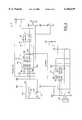
- FIG. 8is a detailed electric schematic of the sensor.
- a sensor 10sends distress information when a user wearing the sensor becomes unconscious or when the user manually signals the need for assistance.
- gravitynormally pulls the body downward. In such cases, the individual can no longer maintain his/her body parallel to a vertical axis and the angle of the person's body changes relative to that axis. Detection of this change may be used to set off a switch that can enable a transmitter.
- Sensor 10is a pager like device worn by a use 12 on a belt 14.
- Sensor 10includes an omni-directional tilt switch which is placed perpendicular with respect to belt 14. This position is chosen as the location of the tilt switch in sensor 10 because this position is often likely to be substantially parallel to a vertical axis 16 running through the user when the user is standing upright.
- a critical angle ⁇ C between the waist of user 12 and vertical axis 16 that causes the tilt switch in sensor 10 to activate the transmitterfalls within the range of 32° to 42°. This critical angle range is sensitive enough to detect the vast majority of collapsed positions, without being overly sensitive to activate the transmitter.
- the most preferred critical angle for activation of the present alarmis determined to be 37° from vertical axis 16.
- sensor 10generally includes an emergency indicator input 18 interfaced with a control circuit 20.
- Control circuit 20controls the operation of a transmitter 22 and an audible alarm 24.
- Control circuit 20controls transmitter 22 to transmit distress information in case of an emergency.
- Control circuit 20controls audible alarm 24 prior to transmission of distress information to alert user 12 that the distress information will be transmitted unless the user desires otherwise.
- Control circuit 20also includes a user feedback circuit 26.
- User feedback circuit 26enables user 12 to know the state of sensor 10 in order to manually terminate the transmission of distress information.
- a power supply 42such as a battery is connected to control circuit 20 to provide power to sensor 10.
- emergency indicator input 18includes a panic switch 28, a transmitter enable switch 30, a tilt switch 32, a sensor monitor activation switch 34, and a low sensor battery detection switch 36.
- Control circuit 20includes transmitter control logic 38, timer 40, and audible alarm control logic 46. Control circuit 20 monitors the inputs of emergency indicator input 18 and upon activation of an input controls audible alarm 24 to generate an audible alarm signal. After a predetermined time interval, if user 12 does not reenable sensor 10 in response to the audible alarm signal, then control circuit 20 controls transmitter 22 to transmit distress information.
- panic switch 28can directly transmit distress information using sensor 10 by activating panic switch 28.
- panic switch 28Upon activation, panic switch 28 provides a panic signal directly to transmitter control logic 38.
- Transmitter control logic 38then controls transmitter 22 to transmit distress information.
- Tilt switch 32detects a change of angle of the body of user 12 relative to vertical axis 16. Should user 12 fall while working or lose consciousness while sitting or standing, the angle of the body of user 12 deviates from vertical axis 16. This deviation activates tilt switch 32. Control circuit 20 then tests for an emergency condition before controlling transmitter 22 to transmit distress information. If the deviation from vertical axis 16 is continued for more than a predetermined time interval such as ten seconds and user 12 has not manually reset (disabled) sensor 10 using transmitter enable switch 30 or has returned to the normal, upright, substantially vertical position, control circuit 20 controls transmitter 22 to transmit distress information.
- a predetermined time intervalsuch as ten seconds and user 12 has not manually reset (disabled) sensor 10 using transmitter enable switch 30 or has returned to the normal, upright, substantially vertical position
- timer 40determines if tilt switch 32 has been activated for more than the predetermined time interval. After the predetermined time interval has expired, timer 40 provides a timer signal to transmitter control logic 38. Transmitter control logic 38 then controls transmitter 22 to transmit distress information. User 12 resets timer 40 by activating transmitter enable switch 30.
- tilt switch 32activates when the critical angle ⁇ C falls within a range of 32° to 42° (no matter which direction the body of user 12 deviates from vertical axis 16).
- Tilt switch 32is an omni-directional tilt switch that is sensitive to omni-directional deviations from vertical axis 16 falling within the specific critical range.
- audible alarm control logic 46 of control circuit 20In response to activation of tilt switch 32, audible alarm control logic 46 of control circuit 20 immediately controls audible alarm 24 to generate an audible alarm signal.
- the audible alarm signalalerts user 12 that tilt switch 32 has been activated and that transmitter 22 will transmit distress information after the predetermined time interval unless user 12 reenables (disables) timer 40 by activating transmitter enable switch 30.
- sensor monitor activation sensor 34detects whether user 12 is wearing sensor 10.
- sensor 10is a pager like device worn on belt 14.
- Belt 14includes a clip 48 which slips into a corresponding slot 50 provided on back of sensor 10 when user 12 is wearing the sensor on the belt.
- Sensor monitor activation switch 34monitors sensor 10 to determine if clip 48 is inserted into slot 50. If clip 48 is inserted into slot 50, then sensor monitor activation switch 34 determines that user 12 is wearing sensor 10. However, if clip 48 is not inserted into slot 50, then sensor monitor activation switch 34 determines that user 12 is not wearing sensor 10. In this case, sensor monitor activation switch 34 activates.
- control circuit 20tests for an emergency condition before controlling transmitter 22 to transmit distress information. If user 12 is not wearing sensor 10 for more than a predetermined time interval and user 12 has not manually reset (disabled) sensor 10 using transmitter enable switch 30 or has put sensor 10 back on, control circuit 20 controls transmitter 22 to transmit distress information.
- timer 40determines if sensor monitor activation switch 34 has been activated for more than the predetermined time interval. After the predetermined time interval has expired, timer 40 provides a timer signal to transmitter control logic 38. Transmitter control logic 38 then controls transmitter 22 to transmit distress information. User 12 resets timer 40 by activating transmitter enable switch 30.
- audible alarm control logic 46In response to activation of sensor monitor activation switch 34, audible alarm control logic 46 immediately controls audible alarm 24 to generate an audible alarm signal.
- the audible alarm signalalerts user 12 that sensor monitor activation switch 34 has been activated and that transmitter 22 will transmit distress information after the predetermined time interval unless user 12 reenables (disables) timer 40 by activating transmitter enable switch 30.
- low sensor battery detection switch 36detects whether power supply 42 has enough power to ensure the proper operation of sensor 10. Low sensor battery detection switch 36 activates when the power provided by power supply 42 to sensor 10 falls below a predetermined level.
- control circuit 20In response to low sensor battery detection switch 36 activating, control circuit 20 tests for an emergency condition before controlling transmitter 22 to transmit distress information. If the power falls below the predetermined level for a predetermined time period, control circuit 20 controls transmitter 22 to transmit distress information.
- timer 40determines if low sensor battery detection switch 36 has been activated for more than the predetermined time interval. After the predetermined time interval has expired, timer 40 provides a timer signal to transmitter control logic 38. Transmitter control logic 38 then controls transmitter 22 to transmit distress information. User 12 resets timer 40 by activating transmitter enable switch 30.
- audible alarm control logic 46In response to activation of low sensor battery detection switch 36, audible alarm control logic 46 immediately controls audible alarm 24 to generate an audible alarm signal.
- the audible alarm signalalerts user 12 that low sensor battery detection switch 34 has been activated and that transmitter 22 will transmit distress information after the predetermined time interval.
- Alarm system 70includes sensor 10, a receiver 54, and a central office 60.
- Transmitter 22 of sensor 10transmits distress information over a communication link 52 to a receiver 54.
- Receiver 54is a stand alone device that is placed in the home of user 12.
- Receiver 54is connected to an electrical outlet of the house to receive power and may include a temporary standby direct voltage source.
- communication link 52is a radio frequency communication link such that transmitter 22 and receiver 54 communicate with radio frequency signals.
- receiver 54Upon receiving distress information, receiver 54 activates an auto-dialer 56.
- Auto-dialer 56makes a telephone call over telephone line 58 to central office 60 to provide audio communication between user 12 and personnel at the central office monitoring the user in response to the distress information.
- Auto-dialer 56may also establish video communication with personnel at the central office via a cable line 62 in response to the distress information.
- alarm system 70Another feature of alarm system 70 is that sensor 10 and receiver 54 exchange polling information over communication link 52.
- the polling informationenables personnel at central office 60 to determine if user 12 moves outside of a predetermined safety area from receiver 54 while wearing sensor 10.
- transmitter 22transmits polling signals periodically to receiver 54.
- Receiver 54measures the magnitude of the polling signals to determine if the magnitude is greater than a predetermined magnitude level.
- the magnitude of the polling signalsis inversely proportional to the distance between sensor 10 and receiver 54.
- the predetermined magnitude levelcan be set to correspond to a safety distance from receiver 54 that user 12 can move about. Upon moving out of the safety area, the magnitude of the polling signal received by receiver 54 will be lower than the predetermined magnitude level.
- Receiver 54may then communicate with sensor 10 to activate audible alarm 24 to alert user 12 that the user has moved out of the predetermined safety area. Receiver 54 tests for an emergency condition before transmitting distress information. If the magnitude of the polling signal received by receiver 54 is less than the predetermined magnitude level for more than a predetermined time interval and user 12 has not manually reset sensor 10, then receiver 54 transmits distress information.
- receiver 54In response to a polling signal received by receiver 54 having a low magnitude, receiver 54 controls audible alarm control logic 46 to generate an audible alarm signal.
- the audible alarm signalalerts user 12 that the user has moved out of the predetermined safety area and that transmitter 22 will transmit distress information after the predetermined time interval unless user 12 reenables (disables) timer 40 by activating transmitter enable switch 30.
- Sensor 10includes two tilt switches 32(a-b). Two tilt switches are employed to provide finer resolution for selecting the range of the critical angle ⁇ C .
- Timer 40includes a PIC12C508 microprocessor 72.
- Microprocessor 72has four inputs 74(a-d). Input 74a connects tilt switches 32(a-b) with microprocessor 72. Input 74c connects panic switch 28 and transmitter enable switch 30 to microprocessor 72. Input 74d connects low sensor battery detection switch to microprocessor 72.
- Microprocessor 72includes an output 76a. Output 76a connects microprocessor 72 to a microprocessor 78 of transmitter control logic 38. Microprocessor 78 is connected to transmitter 22.
Landscapes
- Business, Economics & Management (AREA)
- Emergency Management (AREA)
- Physics & Mathematics (AREA)
- General Physics & Mathematics (AREA)
- Engineering & Computer Science (AREA)
- Computer Security & Cryptography (AREA)
- Health & Medical Sciences (AREA)
- General Health & Medical Sciences (AREA)
- Gerontology & Geriatric Medicine (AREA)
- Transmitters (AREA)
- Alarm Systems (AREA)
Abstract
Description
Claims (12)
Priority Applications (4)
| Application Number | Priority Date | Filing Date | Title |
|---|---|---|---|
| US09/267,241US6166639A (en) | 1999-03-12 | 1999-03-12 | Personal emergency response system |
| AU37319/00AAU3731900A (en) | 1999-03-12 | 2000-03-09 | Personal emergency response system |
| PCT/US2000/006087WO2000054236A1 (en) | 1999-03-12 | 2000-03-09 | Personal emergency response system |
| CA002361225ACA2361225C (en) | 1999-03-12 | 2000-03-09 | Personal emergency response system |
Applications Claiming Priority (1)
| Application Number | Priority Date | Filing Date | Title |
|---|---|---|---|
| US09/267,241US6166639A (en) | 1999-03-12 | 1999-03-12 | Personal emergency response system |
Publications (1)
| Publication Number | Publication Date |
|---|---|
| US6166639Atrue US6166639A (en) | 2000-12-26 |
Family
ID=23017929
Family Applications (1)
| Application Number | Title | Priority Date | Filing Date |
|---|---|---|---|
| US09/267,241Expired - LifetimeUS6166639A (en) | 1999-03-12 | 1999-03-12 | Personal emergency response system |
Country Status (4)
| Country | Link |
|---|---|
| US (1) | US6166639A (en) |
| AU (1) | AU3731900A (en) |
| CA (1) | CA2361225C (en) |
| WO (1) | WO2000054236A1 (en) |
Cited By (27)
| Publication number | Priority date | Publication date | Assignee | Title |
|---|---|---|---|---|
| US6333694B2 (en) | 2000-03-09 | 2001-12-25 | Advanced Marketing Systems Corporation | Personal emergency response system |
| US20020145514A1 (en)* | 2001-04-04 | 2002-10-10 | Tel-Tron Systems Solutions | Emergency call system using wireless, direct connect and telephone subsystems |
| US6646549B2 (en) | 2001-04-04 | 2003-11-11 | Brian Dawson | Emergency call network and system with graphical user interface |
| US20030210149A1 (en)* | 2002-05-07 | 2003-11-13 | Yoav Reisman | Monitoring device |
| FR2839800A1 (en)* | 2002-05-17 | 2003-11-21 | Haute Frequence Ingenierie | Alarm system for isolated workman includes radio transmitter communicating with station linked to telephone network to send pre-recorded message |
| US6765992B2 (en) | 2001-04-04 | 2004-07-20 | Brian Dawson | Emergency call system and method with attendant and resident pendant actuation |
| US20040183283A1 (en)* | 2002-12-18 | 2004-09-23 | Buckman Robert F. | Air bag inflation device |
| US20060098088A1 (en)* | 2004-11-09 | 2006-05-11 | International Business Machines Corporation | Personal multi-information recorder |
| US7147615B2 (en) | 2001-06-22 | 2006-12-12 | Baxter International Inc. | Needle dislodgement detection |
| US20070035415A1 (en)* | 2005-08-11 | 2007-02-15 | Dawson N R | System and method for programming a code of an emergency call transmitter |
| US20070035402A1 (en)* | 2005-08-11 | 2007-02-15 | Dawson N R | System and method for determining the location of a resident during an emergency within a monitored area having a plurality of residences |
| CN100405412C (en)* | 2005-09-12 | 2008-07-23 | 朱水林 | Structure of multifunctional monitoring and tracing device worn on human body, and its monitoring and tracing method |
| US20090322513A1 (en)* | 2008-06-27 | 2009-12-31 | Franklin Dun-Jen Hwang | Medical emergency alert system and method |
| US20100201526A1 (en)* | 2009-02-06 | 2010-08-12 | Marjan Hafezi | Pregnancy Belt |
| US20100217533A1 (en)* | 2009-02-23 | 2010-08-26 | Laburnum Networks, Inc. | Identifying a Type of Motion of an Object |
| US20100285771A1 (en)* | 2009-05-11 | 2010-11-11 | Peabody Steven R | System containing location-based personal emergency response device |
| US20110066064A1 (en)* | 2009-09-15 | 2011-03-17 | Wellcore Corporation | Method and System for Analyzing Breathing of a User |
| US20110066383A1 (en)* | 2009-09-15 | 2011-03-17 | Wellcore Corporation | Indentifying One or More Activities of an Animate or Inanimate Object |
| US8114043B2 (en) | 2008-07-25 | 2012-02-14 | Baxter International Inc. | Electromagnetic induction access disconnect sensor |
| US8529490B2 (en) | 2002-04-10 | 2013-09-10 | Baxter International Inc. | Systems and methods for dialysis access disconnection |
| US8660517B2 (en) | 2011-10-07 | 2014-02-25 | Jason Paul DeMont | Personal assistance monitoring system |
| US8708946B2 (en) | 2002-04-10 | 2014-04-29 | Baxter International Inc. | Access disconnection systems using conductive contacts |
| US8920356B2 (en) | 2002-04-10 | 2014-12-30 | Baxter International Inc. | Conductive polymer materials and applications thereof including monitoring and providing effective therapy |
| US9107615B2 (en) | 2002-12-18 | 2015-08-18 | Active Protective Technologies, Inc. | Method and apparatus for body impact protection |
| US10155082B2 (en) | 2002-04-10 | 2018-12-18 | Baxter International Inc. | Enhanced signal detection for access disconnection systems |
| USD954580S1 (en)* | 2020-04-01 | 2022-06-14 | Freeus, Llc | Mobile personal emergency response system device |
| US11800996B2 (en) | 2019-08-20 | 2023-10-31 | Koninklijke Philips N.V. | System and method of detecting falls of a subject using a wearable sensor |
Families Citing this family (3)
| Publication number | Priority date | Publication date | Assignee | Title |
|---|---|---|---|---|
| AUPR113900A0 (en)* | 2000-10-31 | 2000-11-23 | Commonwealth Scientific And Industrial Research Organisation | A monitoring system |
| US10645562B2 (en) | 2004-09-21 | 2020-05-05 | Agis Software Development Llc | Method to provide ad hoc and password protected digital and voice networks |
| GB0712562D0 (en)* | 2007-06-28 | 2007-08-08 | Brett Marsha L | Personal emergency alarm system |
Citations (8)
| Publication number | Priority date | Publication date | Assignee | Title |
|---|---|---|---|---|
| US3634885A (en)* | 1969-11-17 | 1972-01-11 | James H Barkley | Electronic medical warning device |
| US3866204A (en)* | 1973-07-19 | 1975-02-11 | James H Barkley | Electronic medical warning device |
| US4284986A (en)* | 1980-06-23 | 1981-08-18 | Carlos Amortegui | Shirt-pocket medical alert device |
| US4667188A (en)* | 1985-04-25 | 1987-05-19 | Cable Electric Products, Inc. | Portable alarm |
| US4829285A (en)* | 1987-06-11 | 1989-05-09 | Marc I. Brand | In-home emergency assist device |
| US4978946A (en)* | 1987-08-13 | 1990-12-18 | Talkie Tooter (Canada) Ltd. | Personal security communication system |
| US5396227A (en)* | 1991-06-26 | 1995-03-07 | Jurismonitor, Inc. | Electronic system and method for monitoring compliance with a protective order |
| US5990793A (en)* | 1994-09-02 | 1999-11-23 | Safety Tech Industries, Inc. | Firefighters integrated communication and safety system |
- 1999
- 1999-03-12USUS09/267,241patent/US6166639A/ennot_activeExpired - Lifetime
- 2000
- 2000-03-09CACA002361225Apatent/CA2361225C/ennot_activeExpired - Lifetime
- 2000-03-09AUAU37319/00Apatent/AU3731900A/ennot_activeAbandoned
- 2000-03-09WOPCT/US2000/006087patent/WO2000054236A1/enactiveApplication Filing
Patent Citations (8)
| Publication number | Priority date | Publication date | Assignee | Title |
|---|---|---|---|---|
| US3634885A (en)* | 1969-11-17 | 1972-01-11 | James H Barkley | Electronic medical warning device |
| US3866204A (en)* | 1973-07-19 | 1975-02-11 | James H Barkley | Electronic medical warning device |
| US4284986A (en)* | 1980-06-23 | 1981-08-18 | Carlos Amortegui | Shirt-pocket medical alert device |
| US4667188A (en)* | 1985-04-25 | 1987-05-19 | Cable Electric Products, Inc. | Portable alarm |
| US4829285A (en)* | 1987-06-11 | 1989-05-09 | Marc I. Brand | In-home emergency assist device |
| US4978946A (en)* | 1987-08-13 | 1990-12-18 | Talkie Tooter (Canada) Ltd. | Personal security communication system |
| US5396227A (en)* | 1991-06-26 | 1995-03-07 | Jurismonitor, Inc. | Electronic system and method for monitoring compliance with a protective order |
| US5990793A (en)* | 1994-09-02 | 1999-11-23 | Safety Tech Industries, Inc. | Firefighters integrated communication and safety system |
Cited By (39)
| Publication number | Priority date | Publication date | Assignee | Title |
|---|---|---|---|---|
| US6333694B2 (en) | 2000-03-09 | 2001-12-25 | Advanced Marketing Systems Corporation | Personal emergency response system |
| US6870906B2 (en) | 2001-04-04 | 2005-03-22 | Brian Dawson | Emergency call system using wireless, direct connect and telephone subsystems |
| US20020145514A1 (en)* | 2001-04-04 | 2002-10-10 | Tel-Tron Systems Solutions | Emergency call system using wireless, direct connect and telephone subsystems |
| US6646549B2 (en) | 2001-04-04 | 2003-11-11 | Brian Dawson | Emergency call network and system with graphical user interface |
| US6765992B2 (en) | 2001-04-04 | 2004-07-20 | Brian Dawson | Emergency call system and method with attendant and resident pendant actuation |
| US7147615B2 (en) | 2001-06-22 | 2006-12-12 | Baxter International Inc. | Needle dislodgement detection |
| US10155082B2 (en) | 2002-04-10 | 2018-12-18 | Baxter International Inc. | Enhanced signal detection for access disconnection systems |
| US8529490B2 (en) | 2002-04-10 | 2013-09-10 | Baxter International Inc. | Systems and methods for dialysis access disconnection |
| US8920356B2 (en) | 2002-04-10 | 2014-12-30 | Baxter International Inc. | Conductive polymer materials and applications thereof including monitoring and providing effective therapy |
| US8801646B2 (en) | 2002-04-10 | 2014-08-12 | Baxter International Inc. | Access disconnection systems with arterial and venous line conductive pathway |
| US8708946B2 (en) | 2002-04-10 | 2014-04-29 | Baxter International Inc. | Access disconnection systems using conductive contacts |
| US6853304B2 (en)* | 2002-05-07 | 2005-02-08 | Dmatek Ltd. | Monitoring device |
| US20030210149A1 (en)* | 2002-05-07 | 2003-11-13 | Yoav Reisman | Monitoring device |
| FR2839800A1 (en)* | 2002-05-17 | 2003-11-21 | Haute Frequence Ingenierie | Alarm system for isolated workman includes radio transmitter communicating with station linked to telephone network to send pre-recorded message |
| US7017195B2 (en)* | 2002-12-18 | 2006-03-28 | Buckman Robert F | Air bag inflation device |
| US20040183283A1 (en)* | 2002-12-18 | 2004-09-23 | Buckman Robert F. | Air bag inflation device |
| US9107615B2 (en) | 2002-12-18 | 2015-08-18 | Active Protective Technologies, Inc. | Method and apparatus for body impact protection |
| US10149638B2 (en) | 2002-12-18 | 2018-12-11 | Active Protective Technologies, Inc. | Method and apparatus for body impact protection |
| US20090207252A1 (en)* | 2004-11-09 | 2009-08-20 | Mandayam Thondanur Raghunath | Personal multi-information recorder |
| US7525568B2 (en)* | 2004-11-09 | 2009-04-28 | International Business Machines Corporation | Personal multi-information recorder |
| US20060098088A1 (en)* | 2004-11-09 | 2006-05-11 | International Business Machines Corporation | Personal multi-information recorder |
| US7315258B2 (en) | 2005-08-11 | 2008-01-01 | Dawson N Rick | System and method for programming a code of an emergency call transmitter |
| US20070035402A1 (en)* | 2005-08-11 | 2007-02-15 | Dawson N R | System and method for determining the location of a resident during an emergency within a monitored area having a plurality of residences |
| US7307522B2 (en) | 2005-08-11 | 2007-12-11 | Dawson N Rick | System and method for determining the location of a resident during an emergency within a monitored area having a plurality of residences |
| US20070035415A1 (en)* | 2005-08-11 | 2007-02-15 | Dawson N R | System and method for programming a code of an emergency call transmitter |
| CN100405412C (en)* | 2005-09-12 | 2008-07-23 | 朱水林 | Structure of multifunctional monitoring and tracing device worn on human body, and its monitoring and tracing method |
| US20090322513A1 (en)* | 2008-06-27 | 2009-12-31 | Franklin Dun-Jen Hwang | Medical emergency alert system and method |
| US8114043B2 (en) | 2008-07-25 | 2012-02-14 | Baxter International Inc. | Electromagnetic induction access disconnect sensor |
| US8632486B2 (en) | 2008-07-25 | 2014-01-21 | Baxter International Inc. | Electromagnetic induction access disconnect systems |
| US20100201526A1 (en)* | 2009-02-06 | 2010-08-12 | Marjan Hafezi | Pregnancy Belt |
| US20100217533A1 (en)* | 2009-02-23 | 2010-08-26 | Laburnum Networks, Inc. | Identifying a Type of Motion of an Object |
| US8116724B2 (en) | 2009-05-11 | 2012-02-14 | Vocare, Inc. | System containing location-based personal emergency response device |
| US20100285771A1 (en)* | 2009-05-11 | 2010-11-11 | Peabody Steven R | System containing location-based personal emergency response device |
| US8972197B2 (en) | 2009-09-15 | 2015-03-03 | Numera, Inc. | Method and system for analyzing breathing of a user |
| US20110066383A1 (en)* | 2009-09-15 | 2011-03-17 | Wellcore Corporation | Indentifying One or More Activities of an Animate or Inanimate Object |
| US20110066064A1 (en)* | 2009-09-15 | 2011-03-17 | Wellcore Corporation | Method and System for Analyzing Breathing of a User |
| US8660517B2 (en) | 2011-10-07 | 2014-02-25 | Jason Paul DeMont | Personal assistance monitoring system |
| US11800996B2 (en) | 2019-08-20 | 2023-10-31 | Koninklijke Philips N.V. | System and method of detecting falls of a subject using a wearable sensor |
| USD954580S1 (en)* | 2020-04-01 | 2022-06-14 | Freeus, Llc | Mobile personal emergency response system device |
Also Published As
| Publication number | Publication date |
|---|---|
| WO2000054236A1 (en) | 2000-09-14 |
| CA2361225C (en) | 2007-08-07 |
| CA2361225A1 (en) | 2000-09-14 |
| AU3731900A (en) | 2000-09-28 |
Similar Documents
| Publication | Publication Date | Title |
|---|---|---|
| US6333694B2 (en) | Personal emergency response system | |
| US6166639A (en) | Personal emergency response system | |
| US4829285A (en) | In-home emergency assist device | |
| US5461365A (en) | Multi-hazard alarm system using selectable power-level transmission and localization | |
| US5650770A (en) | Self-locating remote monitoring systems | |
| US8149112B2 (en) | Multi-hazard alarm system using selectable power-level transmission and localization | |
| JP3124757U (en) | Falling emergency call device | |
| JPH10155749A (en) | System for monitoring and informing about human health condition | |
| GB2323196A (en) | Automatic fall alarm | |
| US20140375451A1 (en) | Smart monitoring sensor system for monitoring mobility | |
| CN108053612A (en) | Falling over of human body monitor system and its automatic alarm rescue method | |
| EP0857341B1 (en) | Self-locating remote monitoring systems | |
| JP2003036492A (en) | Signal monitoring method, wandering / theft prevention system, wanderer / stolen object tracking support system, care support system, signal monitoring terminal, signal monitoring program, wireless communication terminal, and wireless communication program | |
| WO2001075834A1 (en) | Apparatus and method for detecting an inclination of a body | |
| JP2002288771A (en) | Emergency transmitter | |
| JP3830890B2 (en) | Bathroom monitoring device | |
| WO2006137099A2 (en) | System and method of remote monitoring and relief via gsm | |
| KR20020075846A (en) | The method of informing health care and warning sudden death by using mobile and a pulsation watching appliance. | |
| KR20160120893A (en) | Wandering detector | |
| CN211882572U (en) | A smart crutch | |
| JP2004070842A (en) | Error reporting system | |
| JPH0695646B2 (en) | Portable emergency reporting device | |
| JPH04285529A (en) | Device for detecting abnormality occurrence of old people or the like | |
| TWM392408U (en) | Emergency device for warning falling-down | |
| JP2720141B2 (en) | Body abnormality remote detection system |
Legal Events
| Date | Code | Title | Description |
|---|---|---|---|
| AS | Assignment | Owner name:ADVANCED MARKETING SYSTEMS CORPORATION, MICHIGAN Free format text:ASSIGNMENT OF ASSIGNORS INTEREST;ASSIGNORS:PIERCE, DOUGLAS;PROUGH, JEFFREY S.;REEL/FRAME:009892/0995 Effective date:19990401 | |
| STCF | Information on status: patent grant | Free format text:PATENTED CASE | |
| AS | Assignment | Owner name:GUARDIAN MEDICAL MONITORING, INC., MICHIGAN Free format text:ASSIGNMENT OF ASSIGNORS INTEREST;ASSIGNOR:PIERCE, DOUGLAS;REEL/FRAME:014953/0596 Effective date:20031218 | |
| FPAY | Fee payment | Year of fee payment:4 | |
| FPAY | Fee payment | Year of fee payment:8 | |
| FEPP | Fee payment procedure | Free format text:PAT HOLDER CLAIMS SMALL ENTITY STATUS, ENTITY STATUS SET TO SMALL (ORIGINAL EVENT CODE: LTOS); ENTITY STATUS OF PATENT OWNER: SMALL ENTITY | |
| FPAY | Fee payment | Year of fee payment:12 | |
| AS | Assignment | Owner name:GUARDIAN MEDICAL MONITORING, LLC, MICHIGAN Free format text:CONVERSION OF CORPORATION TO LLC;ASSIGNOR:GUARDIAN MEDICAL MONITORING, INC.;REEL/FRAME:041941/0325 Effective date:20170227 | |
| AS | Assignment | Owner name:PACIFIC WESTERN BANK, MARYLAND Free format text:ACKNOWLEDGMENT OF SECURITY INTEREST IN INTELLECTUAL PROPERTY;ASSIGNORS:GA BUSINESS PURCHASER LLC;GA NON-UNION GUARD SERVICES PURCHASER LLC;GA UNION GUARD SERVICES PURCHASER LLC;AND OTHERS;REEL/FRAME:042025/0184 Effective date:20170228 | |
| AS | Assignment | Owner name:GA UNION GUARD SERVICES PURCHASER LLC, MICHIGAN Free format text:RELEASE OF SECURITY INTEREST IN INTELLECTUAL PROPERTY;ASSIGNOR:PACIFIC WESTERN BANK;REEL/FRAME:058264/0331 Effective date:20211123 Owner name:GA NON-UNION GUARD SERVICES PURCHASER LLC, MICHIGAN Free format text:RELEASE OF SECURITY INTEREST IN INTELLECTUAL PROPERTY;ASSIGNOR:PACIFIC WESTERN BANK;REEL/FRAME:058264/0331 Effective date:20211123 Owner name:GUARDIAN MEDICAL MONITORING, LLC, MICHIGAN Free format text:RELEASE OF SECURITY INTEREST IN INTELLECTUAL PROPERTY;ASSIGNOR:PACIFIC WESTERN BANK;REEL/FRAME:058264/0331 Effective date:20211123 Owner name:GA BUSINESS PURCHASER LLC, MICHIGAN Free format text:RELEASE OF SECURITY INTEREST IN INTELLECTUAL PROPERTY;ASSIGNOR:PACIFIC WESTERN BANK;REEL/FRAME:058264/0331 Effective date:20211123 |