US6166422A - Inductor with cobalt/nickel core for integrated circuit structure with high inductance and high Q-factor - Google Patents
Inductor with cobalt/nickel core for integrated circuit structure with high inductance and high Q-factorDownload PDFInfo
- Publication number
- US6166422A US6166422AUS09/079,413US7941398AUS6166422AUS 6166422 AUS6166422 AUS 6166422AUS 7941398 AUS7941398 AUS 7941398AUS 6166422 AUS6166422 AUS 6166422A
- Authority
- US
- United States
- Prior art keywords
- metal
- cobalt
- coil
- high magnetic
- integrated circuit
- Prior art date
- Legal status (The legal status is an assumption and is not a legal conclusion. Google has not performed a legal analysis and makes no representation as to the accuracy of the status listed.)
- Expired - Lifetime
Links
Images


Classifications
- H—ELECTRICITY
- H01—ELECTRIC ELEMENTS
- H01F—MAGNETS; INDUCTANCES; TRANSFORMERS; SELECTION OF MATERIALS FOR THEIR MAGNETIC PROPERTIES
- H01F41/00—Apparatus or processes specially adapted for manufacturing or assembling magnets, inductances or transformers; Apparatus or processes specially adapted for manufacturing materials characterised by their magnetic properties
- H01F41/02—Apparatus or processes specially adapted for manufacturing or assembling magnets, inductances or transformers; Apparatus or processes specially adapted for manufacturing materials characterised by their magnetic properties for manufacturing cores, coils, or magnets
- H01F41/04—Apparatus or processes specially adapted for manufacturing or assembling magnets, inductances or transformers; Apparatus or processes specially adapted for manufacturing materials characterised by their magnetic properties for manufacturing cores, coils, or magnets for manufacturing coils
- H01F41/041—Printed circuit coils
- H01F41/046—Printed circuit coils structurally combined with ferromagnetic material
- H—ELECTRICITY
- H01—ELECTRIC ELEMENTS
- H01F—MAGNETS; INDUCTANCES; TRANSFORMERS; SELECTION OF MATERIALS FOR THEIR MAGNETIC PROPERTIES
- H01F17/00—Fixed inductances of the signal type
- H01F17/0006—Printed inductances
- H01F17/0033—Printed inductances with the coil helically wound around a magnetic core
- H—ELECTRICITY
- H01—ELECTRIC ELEMENTS
- H01L—SEMICONDUCTOR DEVICES NOT COVERED BY CLASS H10
- H01L23/00—Details of semiconductor or other solid state devices
- H01L23/52—Arrangements for conducting electric current within the device in operation from one component to another, i.e. interconnections, e.g. wires, lead frames
- H01L23/522—Arrangements for conducting electric current within the device in operation from one component to another, i.e. interconnections, e.g. wires, lead frames including external interconnections consisting of a multilayer structure of conductive and insulating layers inseparably formed on the semiconductor body
- H01L23/5227—Inductive arrangements or effects of, or between, wiring layers
- H—ELECTRICITY
- H01—ELECTRIC ELEMENTS
- H01L—SEMICONDUCTOR DEVICES NOT COVERED BY CLASS H10
- H01L2924/00—Indexing scheme for arrangements or methods for connecting or disconnecting semiconductor or solid-state bodies as covered by H01L24/00
- H01L2924/0001—Technical content checked by a classifier
- H01L2924/0002—Not covered by any one of groups H01L24/00, H01L24/00 and H01L2224/00
Definitions
- This inventionrelates to an inductor for an integrated circuit structure characterized by a high magnetic susceptibility cobalt/nickel core material, and a method of making the inductor.
- active devicessuch as MOS and bipolar transistors are formed either in the semiconductor substrate or on layers, such as epitaxial layers, formed over the substrate.
- Passive electronic devicessuch as resistors and capacitors are also formed either within the semiconductor substrate or on/in conductive materials formed over the surface of the semiconductor substrate.
- inductorsalso comprise devices utilized in the formation of electronic circuits, their formation in integrated circuit structures has been more difficult, due to the large area needed to form an inductor with a useful amount of inductance and a high enough Q-factor, due to the low inductance of the materials conventionally used to form the inductor.
- 5,576,680discloses a process for forming an inductor on a semiconductor substrate wherein first parallel strips of conductive material are deposited over a dielectric layer, which may be a layer of non-conductive high magnetic susceptible material (HMSM). A second layer of a dielectric (which may also be a non-conductive high magnetic susceptible material) is then formed over the parallel strips. If this second layer of dielectric material is not a high magnetic susceptible material, a layer of high magnetic susceptible material is formed over the second dielectric material (to form the core of HMSM of the inductor) and a further dielectric layer is formed over the high magnetic susceptible material. In either instance, filled vias are formed through the dielectric layer(s) down to the ends of the first parallel strips of conductive material.
- HMSMnon-conductive high magnetic susceptible material
- a further layer of metal linesis then formed over the structure and in contact with the filled vias to connect the opposite ends of the first strips of conductive material to thereby form a spiral coil surrounding the HMSM core.
- the type of material which may constitute this layer of HMSMis never identified, however, by Ling.
- Volz U.S. Pat. No. 4,649,755discloses the formation of an inductor wherein narrow conductive strips comprising a first portion of a coil are formed over a substrate, a first dielectric layer is formed over the first portion of the coil, and a magnetic core in the form of a ring is formed over the first dielectric layer. A second dielectric layer is then formed over the magnetic core and a second set of conductive strips, connected to the first conductive strips, is formed over the second dielectric layer.
- Materials said to be suited for the magnetic coreare ferromagnetic amorphous metals. Good ferromagnetic properties are said to be exhibited by amorphous metals which are alloys based on transition metals of the iron group. Especially suited are said to be amorphous metals which are Co-Fe-base alloys, preferably Co x Fe y B 100-x-y where 70 ⁇ x ⁇ 80 and 4 ⁇ y ⁇ 10.
- inductors on semiconductor substratesis not unknown.
- the use of iron as the magnetic material for the core of the inductor, or at least an iron-containing magnetic core such as ferrite or an iron-containing metal alloyseems to be considered essential to the formation of an inductor on a semiconductor substrate with sufficient inductance and high Q factor.
- iron or iron-containing materialas the high magnetic susceptible material for the core of an inductor is well-recognized in the electronics industry
- the formation of integrated circuits structuresrequires the judicial selection of materials which will be compatible with other materials already in use in the fabrication of integrated circuit structures on semiconductor substrates.
- ironis not one of the materials in widespread use in the formation of integrated circuit structures, at least in part due to the ease with which iron is oxidized in the presence of either air or moisture.
- an inductor for an integrated circuit structurecharacterized by high inductance and a high Q-factor which can be constructed as a part of the integrated circuit structure without the need to utilize an unreasonable amount of the area of the semiconductor substrate, and which can be constructed with a high magnetic susceptibility metal core without the introduction of a foreign material into the integrated circuit structure.
- an integrated circuit structureis provided with an inductor formed therein which comprises a metal coil on an insulated surface over a semiconductor substrate, and a high magnetic susceptibility cobalt/nickel metal core located adjacent said metal coil, but spaced therefrom by one or more insulation layers.
- the high magnetic susceptibility cobalt/nickel metal coreis placed between lower and upper portions of the metal coil which are interconnected together by filled vias.
- the metal coilis formed in a serpentine shape in one plane on an insulated surface over the semiconductor substrate, and the high magnetic susceptibility cobalt/nickel metal core is formed over the serpentine coil, but spaced from the serpentine coil by another insulation layer.
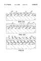
- FIG. 1is a fragmentary vertical cross-sectional view of an early stage of construction of the inductor of the invention showing the formation of the lower portion of the metal coil over a first insulation layer on a semiconductor substrate.
- FIG. 1Ais another fragmentary vertical cross-sectional view of an early stage of construction of the inductor of the invention showing the formation of the lower portion of the metal coil by a different method from that shown in FIG. 1.
- FIG. 2is a top view of the structure shown in FIG. 1 with the photoresist mask removed.
- FIG. 3is a fragmentary vertical cross-sectional view of the structure of FIG. 2 after formation of a planarized second insulation layer over the lower portion of the metal coil.
- FIG. 3Ais a fragmentary vertical cross-sectional view of the formation of a conformal second insulation layer over the metal coil of FIG. 2 instead of the planarized second insulation layer illustrated in FIG. 3.
- FIG. 4is a fragmentary vertical cross-sectional view of the structure of FIG. 3 after formation of the high magnetic susceptibility cobalt/nickel metal core over the planarized second insulation layer.
- FIG. 4Ais a fragmentary vertical cross-sectional view of the structure of FIG. 3A after the formation of the high magnetic susceptibility cobalt/nickel metal core over the conformal second insulation layer.
- FIG. 5is a top view of the structure of FIG. 4.
- FIG. 6is a fragmentary vertical cross-sectional view of the structure of FIGS. 4 and 5 after formation of a third insulation layer over the high magnetic susceptibility cobalt/nickel metal core.
- FIG. 7is a partially cutaway fragmentary top view of the structure of FIG. 6.
- FIG. 8is a fragmentary vertical cross-sectional view of the structure of FIG. 7 taken along lines 8--8 to show formation of filled vias from the lower metal coils through the second and third insulation layers and adjacent the high magnetic susceptibility cobalt/nickel core.
- FIG. 9is a fragmentary vertical cross-sectional view of the structure of FIG. 8 showing the formation of the upper metal coils over the filled metal vias.
- FIG. 10is a top view of the structure of FIG. 9 after removal of the resist mask.
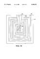
- FIG. 11is a top view of the inductor of the invention showing the lower and upper coils and the high magnetic susceptibility cobalt/nickel metal core therebetween, but eliminating the layers of insulation for illustrative purposes.
- FIG. 12is a top view of another embodiment of the invention showing a serpentine metal coil formed on a first insulation layer over a semiconductor substrate.
- FIG. 13is a fragmentary vertical cross-sectional view of the structure of FIG. 12 showing the formation of a confirm second layer of insulation over the serpentine metal coil, and a layer of high magnetic susceptibility cobalt/nickel metal formed over the second insulation layer.
- FIG. 14is a fragmentary vertical cross-sectional view of the structure of FIG. 13 showing the formation of a resist mask over the cobalt/nickel layer.
- FIG. 15is a fragmentary vertical cross-sectional view of the structure of FIG. 14 after etching of the cobalt/nickel layer to remove a portion thereof over the center contact of the serpentine coil shown in FIG. 12, and after removal of the resist mask.
- FIG. 16is a fragmentary vertical cross-sectional view of the structure of FIG. 15 showing the formation of a conformal third layer of insulation over the cobalt/nickel layer.
- FIG. 17is a fragmentary vertical cross-sectional view of the structure of FIG. 16 showing the planarization of the third layer of insulation.
- FIG. 18is a fragmentary vertical cross-sectional view of the structure of FIG. 17 showing the formation of a metal contact on the surface of the third layer of insulation which electrically connects with the center contact of the serpentine coil of FIG. 12 through a filled via which extends from the metal contact down through the second and third insulation layers to the center contact on the coil.
- FIG. 19is a top view of a portion of the structure of FIG. 18, showing the metal contact to the center contact of th e serpentine coil, but with the insulation layers and the high magnetic susceptibility cobalt metal core layer omitted for illustrative purposes only.
- an integrated circuit structureis provided with an inductor formed therein which comprises a metal coil on an insulated surface over a semiconductor
- the high magnetic susceptibility cobalt/nickel metal corelocated adjacent said metal coil, but spaced therefrom by one or more insulation layers.
- the high magnetic susceptibility cobalt/nickel metal coreis placed between lower and upper portions of the metal coil which are interconnected together by filled vias.
- the metal coilis formed in a serpentine shape in one plane on an insulated surface over the semiconductor substrate, and the high magnetic susceptibility cobalt/nickel metal core is formed over the serpentine coil, but spaced from the serpentine coil by another insulation layer.
- cobalt/nickel metalin the expression "high magnetic susceptibility cobalt/nickel metal core” is meant a metal selected from the group consisting of cobalt metal, nickel metal, and an alloy of the two metals.
- Cobalt and nickelunlike other known inductor core material (e.g., such as iron-based core materials), provide the desired high magnetic susceptibility metal for the core of the inductor without introducing a foreign material into the integrated circuit structure.
- Cobalt and nickelhave both been previously used in the formation of metal silicide contacts in integrated circuit structures. Of the two metals, the use of cobalt for the core material is preferred.
- the deposition of the cobalt or nickel metalsmay be designed to correspond to the deposition of the same metal elsewhere on the integrated circuit structure, e.g., for the purpose of making metal silicide contacts, in which case no extra processing steps for the deposition may be necessary.
- the cobalt metalshould have a purity of at least 99 wt. % cobalt, preferably at least 99.5 wt. % cobalt, and most preferably at least 99.9 wt. % cobalt.
- the high magnetic susceptibility metal coreis made of nickel
- the nickel metalshould have a purity of at least 99 wt. % nickel, preferably at least 99.5 wt. % nickel, and most preferably at least 99.9 wt. % nickel.
- the high magnetic susceptibility core metalcomprises an alloy of cobalt and nickel, the maximum total impurities should not exceed 1 wt. %, preferably not more than 0.5 wt. %, and preferably not more than 0.1 wt. %.
- FIGS. 1 and 2illustrate the formation of the lower portions of the metal coils for the inductor.
- a semiconductor substrate shown at 2 in FIG. 1may, for example, comprise a single crystal silicon substrate which may have other portions of the integrated circuit structure already constructed in or on substrate 2.
- an insulation layer 6which may comprise any insulation material such as, for example, silicon oxide or silicon nitride, compatible with the formation of integrated circuit structures.
- a series of parallel, spaced apart, metal strips 10are formed on the upper surface of insulation layer to form the lower portions of the metal coils of the inductor. Metal strips 10 may be formed, as shown in FIG.
- metal strips 10such as, for example, aluminum, titanium, tungsten, or copper.
- a second insulation layer 20may then be formed over metal strips 10 and first insulation layer 6, as shown in FIG. 3, which is then planarized by any planarizing method such as by etching or by chemical/mechanical polishing (CMP).
- CMPchemical/mechanical polishing
- the thickness of second insulation layer 20 over the top surfaces of metal strips 10will vary from about 100 Angstroms ( ⁇ ) to about 1000 ⁇ , and preferably will range from about 200 ⁇ to about 500 ⁇ .
- Second insulation layer 20, like first insulation layer 6,may be formed of any insulation material such as, for example, silicon oxide or silicon nitride, compatible with the formation of integrated circuit structures.
- metal strips 10may be formed by first depositing a second insulation layer 20' over the entire surface of first insulation layer 6, and then forming a series of parallel spaced apart grooves or trenches 22 through second insulation layer 20'. Although it is not necessary, formation of uniform depth trenches may be facilitated by selection of a different insulation material for layer 20' than first insulation layer 6, and selection of an etch system selective to the insulation material utilized for underlying first insulation layer 6 so that layer 6 may be used as an etch stop layer. A blanket layer of metal (such as any of the previously described metals) is then deposited over the entire surface to fill trenches 22.
- the structureis then subject to a CMP to remove all metal on the surface of layer 20', leaving a series of spaced apart parallel metal strips in the parallel trenches.
- a further layer of insulation material(which may be the same material as used for second insulation layer 20') will result in the formation of the substantially the same structure as shown in FIG. 3.
- a layer of high magnetic susceptibility cobalt/nickel metalis formed over second insulation layer 20, and then patterned to form high magnetic susceptibility cobalt/nickel metal core 30, as shown in FIGS. 4 and 5.
- the thickness of the cobalt/nickel metal corewill range from at least about 0.1 micrometers ( ⁇ m) up to as much as about 3 ⁇ m.
- the cobalt/nickel metal core thicknesswill range from about 0.5 ⁇ m to about 2 ⁇ m, and most preferably from about 0.7 ⁇ m to about 1 ⁇ m.
- a conformal layer of insulation 20"may be formed over metal strips 10 (FIG. 3A), and the high magnetic susceptibility cobalt/nickel metal layer may then be deposited, planarized, and patterned to form core 30', as shown in FIG. 4A.
- third insulation layer 40is formed over core 30, as shown in FIGS. 6 and 7.
- Third insulation layer 40may be formed of any insulation material such as, for example, silicon oxide or silicon nitride, compatible with the formation of integrated circuit structures.
- the thickness of third insulation layer 40, over cobalt/nickel core 30,will range from at least about 100 ⁇ to about 3000 ⁇ , and preferably will range from about 500 ⁇ to about 1000 ⁇ .
- the upper surface of third insulation layer 40will be planarized, as shown in FIG. 6, to permit formation thereon of the upper metal strips, as will be described below.
- Vias 50are then formed down through third insulation layer 40 and second insulation layer 20 to the opposite ends of metal strips 10, as shown in FIGS. 8-10, and filled with an electrically conductive metal, such as any of the metals used in forming metal strips 10, but preferably tungsten.
- an upper group of parallel, spaced apart metal strips 60are then formed over third insulation layer 40 and in contact with filled vias 50.
- Upper metal strips 60may be formed on third insulation layer 40 by blanket depositing any of the previously discussed metals used in forming lower metal strips 10 and then patterning the resulting metal layer to form metal strips 60, using a photoresist mask 70, as shown in FIG. 9. As best seen in FIG.
- the upper metal strips 60are disposed in parallel to one another on third insulation layer 40, but at an angle to lower metal strips 10, so that a filled via extending up from a first end of one lower metal strip contacts a first end of one of the upper metal strips, while the other end of the same upper metal strip contacts the second end of an adjacent lower metal strip (not the same lower metal strip) so that a continuous metal coil or spiral is formed between the lower metal strips, the filled vias, and the upper metal strips.
- Coil contact pads 62 and 64may then be formed on third insulation layer 40, with filled vias 50 connecting contact pads 62 and 64 with the corresponding lower metal strips which will comprise the ends of the metal coil.
- the upper metal strips 60may be formed by an alternative procedure similar to the procedure described with respect to FIG. 1A.
- a further layer of insulationcould be deposited over third insulation layer 40 and a pattern of parallel trenches could be formed in the insulation layer down to the underlying filled vias, with the pattern of the trenches conforming to the desired pattern of metal strips.
- a layer of metal to be used in forming the metal stripswould then be blanket deposited to fill the trenches, after which the portions of the metal layer not in the trenches would be removed, e.g., polished away by CMP, leaving only the desired metal strips.
- the resulting inductor structureas illustrated in FIG. 11 (with the insulation layers removed for clarity), comprises a continuous metal coil which encircles the high magnetic susceptibility cobalt/nickel metal core, resulting in a high inductance, high Q-factor inductor formed as a part of an integrated circuit structure without the necessity of introducing foreign materials into the integrated circuit structure.
- FIGS. 12-19construction of another embodiment of the high magnetic susceptibility cobalt/nickel metal core inductor of the invention is illustrated.
- a single continuous spiral metal coil or strip 110is formed on a first insulation layer 106 formed over a semiconductor substrate 102 (shown in FIGS. 13-18).
- Metal coil 110is formed with an outer end 112 and a central opposite end 114.
- Metal coil 110may be formed of any metal used in integrated circuit structures such as, for example, aluminum, titanium, tungsten, or copper.
- Metal coil 110may be formed by blanket deposition of a metal layer followed by masking and patterning of the metal coil.
- metal coil 110may be formed using the previously described trench method, by first forming a spiral trench in an additional insulation layer formed over first insulation layer 106, then filling the trench with metal, and then removing any extra metal from the surface of the additional insulation layer by a CMP step.
- a conformal second layer of insulation 120such as a silicon oxide or silicon nitride layer, is then formed over metal coil 110.
- the thickness of this conformal layer of insulationmay range from about 100 ⁇ to about 500 ⁇ , but preferably with range from about 200 ⁇ to about 300 ⁇ . While second insulation layer 120 could be provided with a planarized upper surface, in this embodiment a conformal layer of insulation is preferred to permit location of the high magnetic susceptibility cobalt/nickel metal core between the turns of the serpentine coil 110, as will be discussed below.
- a layer 130 of cobalt/nickel metalto form the high magnetic susceptibility cobalt/nickel metal core material for the inductor.
- Cobalt/nickel metal layer 130is then masked with photoresist mask 134, as shown in FIG. 14, to remove portions of core layer 130 beyond the area delimited by the outer portions of metal coil 110, as well as to remove a central portion of core layer 130 overlying central portion or end 114 of metal coil 110, as shown in FIG. 15.
- the thickness of cobalt/nickel core layer 130 on the portion of conformal insulation layer 120 which is formed over the top surface of metal coil 110should be at least about 0.1 micrometers ( ⁇ m) up to as much as about 3 ⁇ m.
- the cobalt/nickel metal core thicknesswill range from about 0.5 ⁇ m to about 2 ⁇ m, and most preferably from about 0.7 ⁇ m to about 1 ⁇ m.
- Third insulation layer 140is then formed over cobalt/nickel core layer 130, as shown in FIG. 16.
- the thickness of third insulation layer 140 over cobalt/nickel core 130will range from at least about 100 ⁇ to about 3000 ⁇ , and preferably will range from about 500 ⁇ to about 1000 ⁇ .
- Third insulation layer 140may then be planarized, as shown in FIG. 17, to facilitate forming a metal contact thereon to inner coil end 114.
- a via or openingis then cut through third insulation layer 140 and conformal second insulation layer 120 to the top surface of coil end 114 and then filled with a metal such as tungsten to form filled via 144.
- a further metal layeris then formed over the planarized top surface of third insulation layer 140 and patterned to form metal contact 150 over filled via 144.
- a similar metal contactmay be used with a second filled metal via (also not shown) through third insulation layer 140 and conformal second insulation layer 120 to provide an external electrical contact to outer end 112 of metal coil 110.
- outer coil end 112may be designed to directly contact another portion of the integrated circuit structure which would make it unnecessary to provide an external contact to outer coil end 112.
- metal contact 150may comprise an elongated strip (which extends perpendicular to the plane of FIG. 18) which would permit electrical contact being made to coil 110 through elongated contact 150 at the edge of the inductor rather directly above coil end 114 at the middle of the inductor.
- the inventionprovides integrated circuit structures with various forms of inductor structures comprising a continuous metal coil and a high magnetic susceptibility cobalt/nickel metal core, resulting in a high inductance, high Q-factor inductor formed as a part of an integrated circuit structure without the necessity of introducing foreign materials into the integrated circuit structure.
Landscapes
- Engineering & Computer Science (AREA)
- Power Engineering (AREA)
- Microelectronics & Electronic Packaging (AREA)
- Manufacturing & Machinery (AREA)
- Physics & Mathematics (AREA)
- Condensed Matter Physics & Semiconductors (AREA)
- General Physics & Mathematics (AREA)
- Computer Hardware Design (AREA)
- Semiconductor Integrated Circuits (AREA)
- Coils Or Transformers For Communication (AREA)
Abstract
Description
Claims (8)
Priority Applications (1)
| Application Number | Priority Date | Filing Date | Title |
|---|---|---|---|
| US09/079,413US6166422A (en) | 1998-05-13 | 1998-05-13 | Inductor with cobalt/nickel core for integrated circuit structure with high inductance and high Q-factor |
Applications Claiming Priority (1)
| Application Number | Priority Date | Filing Date | Title |
|---|---|---|---|
| US09/079,413US6166422A (en) | 1998-05-13 | 1998-05-13 | Inductor with cobalt/nickel core for integrated circuit structure with high inductance and high Q-factor |
Publications (1)
| Publication Number | Publication Date |
|---|---|
| US6166422Atrue US6166422A (en) | 2000-12-26 |
Family
ID=22150393
Family Applications (1)
| Application Number | Title | Priority Date | Filing Date |
|---|---|---|---|
| US09/079,413Expired - LifetimeUS6166422A (en) | 1998-05-13 | 1998-05-13 | Inductor with cobalt/nickel core for integrated circuit structure with high inductance and high Q-factor |
Country Status (1)
| Country | Link |
|---|---|
| US (1) | US6166422A (en) |
Cited By (63)
| Publication number | Priority date | Publication date | Assignee | Title |
|---|---|---|---|---|
| US6258688B1 (en)* | 2000-03-15 | 2001-07-10 | Taiwan Semiconductor Manufacturing Company | Method to form a high Q inductor |
| US20020008605A1 (en)* | 1999-11-23 | 2002-01-24 | Gardner Donald S. | Integrated transformer |
| US6355535B2 (en)* | 1998-08-07 | 2002-03-12 | Winbond Electronics Corp. | Method and structure of manufacturing a high-Q inductor with an air trench |
| US6396122B1 (en)* | 2000-09-08 | 2002-05-28 | Newport Fab, Llc | Method for fabricating on-chip inductors and related structure |
| US20030005572A1 (en)* | 1999-11-23 | 2003-01-09 | Gardner Donald S. | Integrated inductor |
| US6531945B1 (en)* | 2000-03-10 | 2003-03-11 | Micron Technology, Inc. | Integrated circuit inductor with a magnetic core |
| GB2381130A (en)* | 2001-10-05 | 2003-04-23 | Agere Syst Guardian Corp | A multi-layer inductor formed in a semiconductor |
| US20030184426A1 (en)* | 2001-12-06 | 2003-10-02 | Samsung Electronics Co., Ltd. | Inductor element having a high quality factor |
| US20040157370A1 (en)* | 1999-11-23 | 2004-08-12 | Intel Corporation | Inductors for integrated circuits, integrated circuit components, and integrated circuit packages |
| US20040195647A1 (en)* | 1999-11-23 | 2004-10-07 | Crawford Ankur Mohan | Magnetic layer processing |
| US20040222492A1 (en)* | 2003-05-05 | 2004-11-11 | Gardner Donald S. | On-die micro-transformer structures with magnetic materials |
| US20040240684A1 (en)* | 2003-05-29 | 2004-12-02 | Mark Cerasuolo | Automatic and simultaneous control of loudness and loudness compensation of an audio signal |
| US20050006713A1 (en)* | 2003-02-25 | 2005-01-13 | Sansung Electronics Co., Ltd. | Method for manufacturing magnetic field detecting element |
| US20050017837A1 (en)* | 1999-11-23 | 2005-01-27 | Gardner Donald S. | Integrated transformer |
| US20050170554A1 (en)* | 2002-05-07 | 2005-08-04 | Griglione Michelle D. | Multi-layer inductor formed in a semiconductor substrate and having a core of ferromagnetic material |
| US20060077519A1 (en)* | 2004-09-27 | 2006-04-13 | Floyd Philip D | System and method for providing thermal compensation for an interferometric modulator display |
| US20060164757A1 (en)* | 2005-01-25 | 2006-07-27 | Samsung Electronics Co., Ltd. | Magnetic field sensing device and a fabricating method of the same |
| US20060256420A1 (en)* | 2003-06-24 | 2006-11-16 | Miles Mark W | Film stack for manufacturing micro-electromechanical systems (MEMS) devices |
| US20060257070A1 (en)* | 2003-05-26 | 2006-11-16 | Wen-Jian Lin | Optical interference display cell and method of making the same |
| US20070001762A1 (en)* | 2005-06-30 | 2007-01-04 | Gerhard Schrom | DC-DC converter switching transistor current measurement technique |
| US7250315B2 (en) | 2002-02-12 | 2007-07-31 | Idc, Llc | Method for fabricating a structure for a microelectromechanical system (MEMS) device |
| US20070236774A1 (en)* | 2006-04-10 | 2007-10-11 | Evgeni Gousev | Interferometric optical display system with broadband characteristics |
| US20070247696A1 (en)* | 2006-04-19 | 2007-10-25 | Teruo Sasagawa | Microelectromechanical device and method utilizing a porous surface |
| US7291921B2 (en) | 2003-09-30 | 2007-11-06 | Qualcomm Mems Technologies, Inc. | Structure of a micro electro mechanical system and the manufacturing method thereof |
| US7297471B1 (en) | 2003-04-15 | 2007-11-20 | Idc, Llc | Method for manufacturing an array of interferometric modulators |
| US20070279730A1 (en)* | 2006-06-01 | 2007-12-06 | David Heald | Process and structure for fabrication of mems device having isolated egde posts |
| US20070296056A1 (en)* | 2006-06-27 | 2007-12-27 | Texas Instruments Incorporated | Integrated Circuits Having Controlled Inductances |
| US7349136B2 (en) | 2004-09-27 | 2008-03-25 | Idc, Llc | Method and device for a display having transparent components integrated therein |
| US7369296B2 (en) | 2004-09-27 | 2008-05-06 | Idc, Llc | Device and method for modifying actuation voltage thresholds of a deformable membrane in an interferometric modulator |
| US7369292B2 (en) | 2006-05-03 | 2008-05-06 | Qualcomm Mems Technologies, Inc. | Electrode and interconnect materials for MEMS devices |
| US7373026B2 (en) | 2004-09-27 | 2008-05-13 | Idc, Llc | MEMS device fabricated on a pre-patterned substrate |
| US7382515B2 (en) | 2006-01-18 | 2008-06-03 | Qualcomm Mems Technologies, Inc. | Silicon-rich silicon nitrides as etch stops in MEMS manufacture |
| US7405861B2 (en) | 2004-09-27 | 2008-07-29 | Idc, Llc | Method and device for protecting interferometric modulators from electrostatic discharge |
| US7405863B2 (en) | 2006-06-01 | 2008-07-29 | Qualcomm Mems Technologies, Inc. | Patterning of mechanical layer in MEMS to reduce stresses at supports |
| US7417783B2 (en) | 2004-09-27 | 2008-08-26 | Idc, Llc | Mirror and mirror layer for optical modulator and method |
| US7420728B2 (en) | 2004-09-27 | 2008-09-02 | Idc, Llc | Methods of fabricating interferometric modulators by selectively removing a material |
| US20080252407A1 (en)* | 2005-10-05 | 2008-10-16 | Nxp B.V. | Multi-Layer Inductive Element for Integrated Circuit |
| US7450295B2 (en) | 2006-03-02 | 2008-11-11 | Qualcomm Mems Technologies, Inc. | Methods for producing MEMS with protective coatings using multi-component sacrificial layers |
| US7485236B2 (en) | 2003-08-26 | 2009-02-03 | Qualcomm Mems Technologies, Inc. | Interference display cell and fabrication method thereof |
| US7492502B2 (en) | 2004-09-27 | 2009-02-17 | Idc, Llc | Method of fabricating a free-standing microstructure |
| US7527996B2 (en) | 2006-04-19 | 2009-05-05 | Qualcomm Mems Technologies, Inc. | Non-planar surface structures and process for microelectromechanical systems |
| US7534640B2 (en) | 2005-07-22 | 2009-05-19 | Qualcomm Mems Technologies, Inc. | Support structure for MEMS device and methods therefor |
| US7547568B2 (en) | 2006-02-22 | 2009-06-16 | Qualcomm Mems Technologies, Inc. | Electrical conditioning of MEMS device and insulating layer thereof |
| US7547565B2 (en) | 2005-02-04 | 2009-06-16 | Qualcomm Mems Technologies, Inc. | Method of manufacturing optical interference color display |
| US7550794B2 (en) | 2002-09-20 | 2009-06-23 | Idc, Llc | Micromechanical systems device comprising a displaceable electrode and a charge-trapping layer |
| US7553684B2 (en) | 2004-09-27 | 2009-06-30 | Idc, Llc | Method of fabricating interferometric devices using lift-off processing techniques |
| US7566664B2 (en) | 2006-08-02 | 2009-07-28 | Qualcomm Mems Technologies, Inc. | Selective etching of MEMS using gaseous halides and reactive co-etchants |
| US7623287B2 (en) | 2006-04-19 | 2009-11-24 | Qualcomm Mems Technologies, Inc. | Non-planar surface structures and process for microelectromechanical systems |
| US7630114B2 (en) | 2005-10-28 | 2009-12-08 | Idc, Llc | Diffusion barrier layer for MEMS devices |
| US7652348B1 (en) | 2006-07-27 | 2010-01-26 | National Semiconductor Corporation | Apparatus and method for wafer level fabrication of high value inductors on semiconductor integrated circuits |
| US7684104B2 (en) | 2004-09-27 | 2010-03-23 | Idc, Llc | MEMS using filler material and method |
| US7711239B2 (en) | 2006-04-19 | 2010-05-04 | Qualcomm Mems Technologies, Inc. | Microelectromechanical device and method utilizing nanoparticles |
| US7763546B2 (en) | 2006-08-02 | 2010-07-27 | Qualcomm Mems Technologies, Inc. | Methods for reducing surface charges during the manufacture of microelectromechanical systems devices |
| US7781850B2 (en) | 2002-09-20 | 2010-08-24 | Qualcomm Mems Technologies, Inc. | Controlling electromechanical behavior of structures within a microelectromechanical systems device |
| US20100225435A1 (en)* | 2009-03-04 | 2010-09-09 | Qualcomm Incorporated | Magnetic Film Enhanced Inductor |
| US7795061B2 (en) | 2005-12-29 | 2010-09-14 | Qualcomm Mems Technologies, Inc. | Method of creating MEMS device cavities by a non-etching process |
| US7829425B1 (en)* | 2006-08-15 | 2010-11-09 | National Semiconductor Corporation | Apparatus and method for wafer level fabrication of high value inductors on semiconductor integrated circuits |
| US20100315191A1 (en)* | 2005-10-13 | 2010-12-16 | Xiao T Danny | Patterned magnetic inductors |
| US20140217546A1 (en)* | 2013-02-06 | 2014-08-07 | Taiwan Semiconductor Manufacturing Co., Ltd. | Helical spiral inductor between stacking die |
| US8830557B2 (en) | 2007-05-11 | 2014-09-09 | Qualcomm Mems Technologies, Inc. | Methods of fabricating MEMS with spacers between plates and devices formed by same |
| US10553354B2 (en) | 2017-03-10 | 2020-02-04 | International Business Machines Corporation | Method of manufacturing inductor with ferromagnetic cores |
| CN111768969A (en)* | 2020-06-18 | 2020-10-13 | 北京控制工程研究所 | A method of winding the excitation coil of a Hall thruster |
| US20210280533A1 (en)* | 2018-07-30 | 2021-09-09 | Texas Instruments Incorporated | Crack suppression structure for hv isolation component |
Citations (14)
| Publication number | Priority date | Publication date | Assignee | Title |
|---|---|---|---|---|
| US3609083A (en)* | 1970-03-17 | 1971-09-28 | Bell Telephone Labor Inc | Heat treatment of nickel zinc cobalt ferrite |
| US4649755A (en)* | 1983-12-23 | 1987-03-17 | International Standard Electric Corporation | Sensor for magnetizable materials |
| US5070317A (en)* | 1989-01-17 | 1991-12-03 | Bhagat Jayant K | Miniature inductor for integrated circuits and devices |
| US5372967A (en)* | 1992-01-27 | 1994-12-13 | Motorola, Inc. | Method for fabricating a vertical trench inductor |
| JPH0737711A (en)* | 1993-07-20 | 1995-02-07 | Tokin Corp | Oxide magnetic material and inductor using same |
| US5387551A (en)* | 1992-03-04 | 1995-02-07 | Kabushiki Kaisha Toshiba | Method of manufacturing flat inductance element |
| US5396101A (en)* | 1991-07-03 | 1995-03-07 | Sumitomo Electric Industries, Ltd. | Inductance element |
| US5396527A (en)* | 1992-07-17 | 1995-03-07 | Massachusetts Institute Of Technology | Recovered energy logic circuits |
| US5529831A (en)* | 1993-12-09 | 1996-06-25 | Alps Electric Co., Ltd. | Thin film device |
| US5576680A (en)* | 1994-03-01 | 1996-11-19 | Amer-Soi | Structure and fabrication process of inductors on semiconductor chip |
| US5626789A (en)* | 1991-09-11 | 1997-05-06 | American Research Corp. Of Virginia | Ferrimagnetic core materials for megahertz frequency high flux density transformers and inductors |
| US5635892A (en)* | 1994-12-06 | 1997-06-03 | Lucent Technologies Inc. | High Q integrated inductor |
| US5748523A (en)* | 1992-09-10 | 1998-05-05 | National Semiconductor Corporation | Integrated circuit magnetic memory element having a magnetizable member and at least two conductive winding |
| US5834825A (en)* | 1995-12-27 | 1998-11-10 | Nec Corporation | Semiconductor device having spiral wiring directly covered with an insulating layer containing ferromagnetic particles |
- 1998
- 1998-05-13USUS09/079,413patent/US6166422A/ennot_activeExpired - Lifetime
Patent Citations (14)
| Publication number | Priority date | Publication date | Assignee | Title |
|---|---|---|---|---|
| US3609083A (en)* | 1970-03-17 | 1971-09-28 | Bell Telephone Labor Inc | Heat treatment of nickel zinc cobalt ferrite |
| US4649755A (en)* | 1983-12-23 | 1987-03-17 | International Standard Electric Corporation | Sensor for magnetizable materials |
| US5070317A (en)* | 1989-01-17 | 1991-12-03 | Bhagat Jayant K | Miniature inductor for integrated circuits and devices |
| US5396101A (en)* | 1991-07-03 | 1995-03-07 | Sumitomo Electric Industries, Ltd. | Inductance element |
| US5626789A (en)* | 1991-09-11 | 1997-05-06 | American Research Corp. Of Virginia | Ferrimagnetic core materials for megahertz frequency high flux density transformers and inductors |
| US5372967A (en)* | 1992-01-27 | 1994-12-13 | Motorola, Inc. | Method for fabricating a vertical trench inductor |
| US5387551A (en)* | 1992-03-04 | 1995-02-07 | Kabushiki Kaisha Toshiba | Method of manufacturing flat inductance element |
| US5396527A (en)* | 1992-07-17 | 1995-03-07 | Massachusetts Institute Of Technology | Recovered energy logic circuits |
| US5748523A (en)* | 1992-09-10 | 1998-05-05 | National Semiconductor Corporation | Integrated circuit magnetic memory element having a magnetizable member and at least two conductive winding |
| JPH0737711A (en)* | 1993-07-20 | 1995-02-07 | Tokin Corp | Oxide magnetic material and inductor using same |
| US5529831A (en)* | 1993-12-09 | 1996-06-25 | Alps Electric Co., Ltd. | Thin film device |
| US5576680A (en)* | 1994-03-01 | 1996-11-19 | Amer-Soi | Structure and fabrication process of inductors on semiconductor chip |
| US5635892A (en)* | 1994-12-06 | 1997-06-03 | Lucent Technologies Inc. | High Q integrated inductor |
| US5834825A (en)* | 1995-12-27 | 1998-11-10 | Nec Corporation | Semiconductor device having spiral wiring directly covered with an insulating layer containing ferromagnetic particles |
Non-Patent Citations (4)
| Title |
|---|
| Allen, Mark G., "Integrated Inductors for Low Cost Electronic Packages", IEDM, 1995, pp. 137-141. |
| Allen, Mark G., Integrated Inductors for Low Cost Electronic Packages , IEDM , 1995, pp. 137 141.* |
| Yue, C. Patrick, et al., "A Physical Model for Planar Spiral Inductors on Silicon", IEDM, 1996, pp. 155-158. |
| Yue, C. Patrick, et al., A Physical Model for Planar Spiral Inductors on Silicon , IEDM , 1996, pp. 155 158.* |
Cited By (131)
| Publication number | Priority date | Publication date | Assignee | Title |
|---|---|---|---|---|
| US6355535B2 (en)* | 1998-08-07 | 2002-03-12 | Winbond Electronics Corp. | Method and structure of manufacturing a high-Q inductor with an air trench |
| US7332792B2 (en) | 1999-11-23 | 2008-02-19 | Intel Corporation | Magnetic layer processing |
| US6943658B2 (en) | 1999-11-23 | 2005-09-13 | Intel Corporation | Integrated transformer |
| US20090015363A1 (en)* | 1999-11-23 | 2009-01-15 | Gardner Donald S | Integrated transformer |
| US20030001713A1 (en)* | 1999-11-23 | 2003-01-02 | Gardner Donald S. | Integrated transformer |
| US20030005572A1 (en)* | 1999-11-23 | 2003-01-09 | Gardner Donald S. | Integrated inductor |
| US20050146411A1 (en)* | 1999-11-23 | 2005-07-07 | Gardner Donald S. | Integrated inductor |
| US20020008605A1 (en)* | 1999-11-23 | 2002-01-24 | Gardner Donald S. | Integrated transformer |
| US7327010B2 (en) | 1999-11-23 | 2008-02-05 | Intel Corporation | Inductors for integrated circuits |
| US7299537B2 (en) | 1999-11-23 | 2007-11-27 | Intel Corporation | Method of making an integrated inductor |
| US7791447B2 (en) | 1999-11-23 | 2010-09-07 | Intel Corporation | Integrated transformer |
| US20100295649A1 (en)* | 1999-11-23 | 2010-11-25 | Gardner Donald S | Integrated transformer |
| US7119650B2 (en) | 1999-11-23 | 2006-10-10 | Intel Corporation | Integrated transformer |
| US7087976B2 (en) | 1999-11-23 | 2006-08-08 | Intel Corporation | Inductors for integrated circuits |
| US20040046630A1 (en)* | 1999-11-23 | 2004-03-11 | Gardner Donald S. | Integrated transformer |
| US20060163695A1 (en)* | 1999-11-23 | 2006-07-27 | Intel Corporation | Inductors for integrated circuits |
| US7064646B2 (en)* | 1999-11-23 | 2006-06-20 | Intel Corporation | Integrated inductor |
| US20040157370A1 (en)* | 1999-11-23 | 2004-08-12 | Intel Corporation | Inductors for integrated circuits, integrated circuit components, and integrated circuit packages |
| US20040195647A1 (en)* | 1999-11-23 | 2004-10-07 | Crawford Ankur Mohan | Magnetic layer processing |
| US6815220B2 (en) | 1999-11-23 | 2004-11-09 | Intel Corporation | Magnetic layer processing |
| US7982574B2 (en) | 1999-11-23 | 2011-07-19 | Intel Corporation | Integrated transformer |
| US6988307B2 (en) | 1999-11-23 | 2006-01-24 | Intel Corporation | Method of making an integrated inductor |
| US20040250411A1 (en)* | 1999-11-23 | 2004-12-16 | Gardner Donald S. | Integrated inductor |
| US7434306B2 (en) | 1999-11-23 | 2008-10-14 | Intel Corporation | Integrated transformer |
| US20050017837A1 (en)* | 1999-11-23 | 2005-01-27 | Gardner Donald S. | Integrated transformer |
| US6940147B2 (en) | 1999-11-23 | 2005-09-06 | Intel Corporation | Integrated inductor having magnetic layer |
| US6856228B2 (en) | 1999-11-23 | 2005-02-15 | Intel Corporation | Integrated inductor |
| US6856226B2 (en) | 1999-11-23 | 2005-02-15 | Intel Corporation | Integrated transformer |
| US6870456B2 (en) | 1999-11-23 | 2005-03-22 | Intel Corporation | Integrated transformer |
| US20050062575A1 (en)* | 1999-11-23 | 2005-03-24 | Gardner Donald S. | Integrated transformer |
| US20050133924A1 (en)* | 1999-11-23 | 2005-06-23 | Crawford Ankur M. | Magnetic layer processing |
| US6891461B2 (en) | 1999-11-23 | 2005-05-10 | Intel Corporation | Integrated transformer |
| US20050093669A1 (en)* | 2000-03-10 | 2005-05-05 | Ahn Kie Y. | Integrated circuit inductor with a magnetic core |
| US20030137385A1 (en)* | 2000-03-10 | 2003-07-24 | Ahn Kie Y | Integrated circuit inductor with a magnetic core |
| US6696912B2 (en) | 2000-03-10 | 2004-02-24 | Micron Technology, Inc. | Integrated circuit inductor with a magnetic core |
| US6927666B2 (en) | 2000-03-10 | 2005-08-09 | Micron Technology, Inc. | Integrated circuit inductor with a magnetic core |
| US6853288B2 (en) | 2000-03-10 | 2005-02-08 | Micron Technology, Inc. | Integrated circuit inductor with a magnetic core |
| US6531945B1 (en)* | 2000-03-10 | 2003-03-11 | Micron Technology, Inc. | Integrated circuit inductor with a magnetic core |
| US20040113738A1 (en)* | 2000-03-10 | 2004-06-17 | Ahn Kie Y | Integrated circuit inductor with a magnetic core |
| US6756875B2 (en)* | 2000-03-10 | 2004-06-29 | Micron Technology, Inc. | Integrated circuit inductor with a magnetic core |
| US20030137387A1 (en)* | 2000-03-10 | 2003-07-24 | Ahn Kie Y | Integrated circuit inductor with a magnetic core |
| US6258688B1 (en)* | 2000-03-15 | 2001-07-10 | Taiwan Semiconductor Manufacturing Company | Method to form a high Q inductor |
| US6396122B1 (en)* | 2000-09-08 | 2002-05-28 | Newport Fab, Llc | Method for fabricating on-chip inductors and related structure |
| WO2002058140A3 (en)* | 2001-01-19 | 2003-03-20 | Intel Corp | Integrated inductor |
| US6639298B2 (en) | 2001-06-28 | 2003-10-28 | Agere Systems Inc. | Multi-layer inductor formed in a semiconductor substrate |
| GB2381130B (en)* | 2001-10-05 | 2006-02-01 | Agere Syst Guardian Corp | A multi-layer inductor formed in a semiconductor substrate |
| GB2381130A (en)* | 2001-10-05 | 2003-04-23 | Agere Syst Guardian Corp | A multi-layer inductor formed in a semiconductor |
| US7151429B2 (en)* | 2001-12-06 | 2006-12-19 | Samsung Electronics Co., Ltd. | Inductor element having a high quality factor |
| US20030184426A1 (en)* | 2001-12-06 | 2003-10-02 | Samsung Electronics Co., Ltd. | Inductor element having a high quality factor |
| US7642110B2 (en) | 2002-02-12 | 2010-01-05 | Qualcomm Mems Technologies, Inc. | Method for fabricating a structure for a microelectromechanical systems (MEMS) device |
| US7250315B2 (en) | 2002-02-12 | 2007-07-31 | Idc, Llc | Method for fabricating a structure for a microelectromechanical system (MEMS) device |
| US7132297B2 (en) | 2002-05-07 | 2006-11-07 | Agere Systems Inc. | Multi-layer inductor formed in a semiconductor substrate and having a core of ferromagnetic material |
| US20050170554A1 (en)* | 2002-05-07 | 2005-08-04 | Griglione Michelle D. | Multi-layer inductor formed in a semiconductor substrate and having a core of ferromagnetic material |
| US7550794B2 (en) | 2002-09-20 | 2009-06-23 | Idc, Llc | Micromechanical systems device comprising a displaceable electrode and a charge-trapping layer |
| US7781850B2 (en) | 2002-09-20 | 2010-08-24 | Qualcomm Mems Technologies, Inc. | Controlling electromechanical behavior of structures within a microelectromechanical systems device |
| US7041526B2 (en)* | 2003-02-25 | 2006-05-09 | Samsung Electronics Co., Ltd. | Magnetic field detecting element and method for manufacturing the same |
| US20050006713A1 (en)* | 2003-02-25 | 2005-01-13 | Sansung Electronics Co., Ltd. | Method for manufacturing magnetic field detecting element |
| US20060115918A1 (en)* | 2003-02-25 | 2006-06-01 | Samsung Electronics Co., Ltd. | Method for manufacturing a magnetic field detecting element |
| US7297471B1 (en) | 2003-04-15 | 2007-11-20 | Idc, Llc | Method for manufacturing an array of interferometric modulators |
| US20110068887A1 (en)* | 2003-05-05 | 2011-03-24 | Gardner Donald S | On-die micro-transformer structures with magnetic materials |
| US8471667B2 (en) | 2003-05-05 | 2013-06-25 | Intel Corporation | On-die micro-transformer structures with magnetic materials |
| US7852185B2 (en) | 2003-05-05 | 2010-12-14 | Intel Corporation | On-die micro-transformer structures with magnetic materials |
| US20040222492A1 (en)* | 2003-05-05 | 2004-11-11 | Gardner Donald S. | On-die micro-transformer structures with magnetic materials |
| US20060257070A1 (en)* | 2003-05-26 | 2006-11-16 | Wen-Jian Lin | Optical interference display cell and method of making the same |
| US7706044B2 (en) | 2003-05-26 | 2010-04-27 | Qualcomm Mems Technologies, Inc. | Optical interference display cell and method of making the same |
| US20040240684A1 (en)* | 2003-05-29 | 2004-12-02 | Mark Cerasuolo | Automatic and simultaneous control of loudness and loudness compensation of an audio signal |
| US7616369B2 (en) | 2003-06-24 | 2009-11-10 | Idc, Llc | Film stack for manufacturing micro-electromechanical systems (MEMS) devices |
| US20060256420A1 (en)* | 2003-06-24 | 2006-11-16 | Miles Mark W | Film stack for manufacturing micro-electromechanical systems (MEMS) devices |
| US7485236B2 (en) | 2003-08-26 | 2009-02-03 | Qualcomm Mems Technologies, Inc. | Interference display cell and fabrication method thereof |
| US7291921B2 (en) | 2003-09-30 | 2007-11-06 | Qualcomm Mems Technologies, Inc. | Structure of a micro electro mechanical system and the manufacturing method thereof |
| US7349136B2 (en) | 2004-09-27 | 2008-03-25 | Idc, Llc | Method and device for a display having transparent components integrated therein |
| US20060077519A1 (en)* | 2004-09-27 | 2006-04-13 | Floyd Philip D | System and method for providing thermal compensation for an interferometric modulator display |
| US7369296B2 (en) | 2004-09-27 | 2008-05-06 | Idc, Llc | Device and method for modifying actuation voltage thresholds of a deformable membrane in an interferometric modulator |
| US7405861B2 (en) | 2004-09-27 | 2008-07-29 | Idc, Llc | Method and device for protecting interferometric modulators from electrostatic discharge |
| US7417783B2 (en) | 2004-09-27 | 2008-08-26 | Idc, Llc | Mirror and mirror layer for optical modulator and method |
| US7420728B2 (en) | 2004-09-27 | 2008-09-02 | Idc, Llc | Methods of fabricating interferometric modulators by selectively removing a material |
| US7429334B2 (en) | 2004-09-27 | 2008-09-30 | Idc, Llc | Methods of fabricating interferometric modulators by selectively removing a material |
| US7553684B2 (en) | 2004-09-27 | 2009-06-30 | Idc, Llc | Method of fabricating interferometric devices using lift-off processing techniques |
| US7492502B2 (en) | 2004-09-27 | 2009-02-17 | Idc, Llc | Method of fabricating a free-standing microstructure |
| US7684104B2 (en) | 2004-09-27 | 2010-03-23 | Idc, Llc | MEMS using filler material and method |
| US7373026B2 (en) | 2004-09-27 | 2008-05-13 | Idc, Llc | MEMS device fabricated on a pre-patterned substrate |
| US7253489B2 (en)* | 2005-01-25 | 2007-08-07 | Samsung Electronics Co., Ltd. | Magnetic field sensing device and a fabricating method of the same |
| US20060164757A1 (en)* | 2005-01-25 | 2006-07-27 | Samsung Electronics Co., Ltd. | Magnetic field sensing device and a fabricating method of the same |
| US7338816B2 (en) | 2005-01-25 | 2008-03-04 | Samsung Electronics Co., Ltd. | Magnetic field sensing device and a fabricating method of the same |
| US7547565B2 (en) | 2005-02-04 | 2009-06-16 | Qualcomm Mems Technologies, Inc. | Method of manufacturing optical interference color display |
| US8134548B2 (en) | 2005-06-30 | 2012-03-13 | Micron Technology, Inc. | DC-DC converter switching transistor current measurement technique |
| US8482552B2 (en) | 2005-06-30 | 2013-07-09 | Micron Technology, Inc. | DC-DC converter switching transistor current measurement technique |
| US20070001762A1 (en)* | 2005-06-30 | 2007-01-04 | Gerhard Schrom | DC-DC converter switching transistor current measurement technique |
| US9124174B2 (en) | 2005-06-30 | 2015-09-01 | Micron Technology, Inc. | DC-DC converter switching transistor current measurement technique |
| US7534640B2 (en) | 2005-07-22 | 2009-05-19 | Qualcomm Mems Technologies, Inc. | Support structure for MEMS device and methods therefor |
| US20080252407A1 (en)* | 2005-10-05 | 2008-10-16 | Nxp B.V. | Multi-Layer Inductive Element for Integrated Circuit |
| US20100315191A1 (en)* | 2005-10-13 | 2010-12-16 | Xiao T Danny | Patterned magnetic inductors |
| US7630114B2 (en) | 2005-10-28 | 2009-12-08 | Idc, Llc | Diffusion barrier layer for MEMS devices |
| US7795061B2 (en) | 2005-12-29 | 2010-09-14 | Qualcomm Mems Technologies, Inc. | Method of creating MEMS device cavities by a non-etching process |
| US8394656B2 (en) | 2005-12-29 | 2013-03-12 | Qualcomm Mems Technologies, Inc. | Method of creating MEMS device cavities by a non-etching process |
| US7382515B2 (en) | 2006-01-18 | 2008-06-03 | Qualcomm Mems Technologies, Inc. | Silicon-rich silicon nitrides as etch stops in MEMS manufacture |
| US7547568B2 (en) | 2006-02-22 | 2009-06-16 | Qualcomm Mems Technologies, Inc. | Electrical conditioning of MEMS device and insulating layer thereof |
| US7450295B2 (en) | 2006-03-02 | 2008-11-11 | Qualcomm Mems Technologies, Inc. | Methods for producing MEMS with protective coatings using multi-component sacrificial layers |
| US7643203B2 (en) | 2006-04-10 | 2010-01-05 | Qualcomm Mems Technologies, Inc. | Interferometric optical display system with broadband characteristics |
| US20070236774A1 (en)* | 2006-04-10 | 2007-10-11 | Evgeni Gousev | Interferometric optical display system with broadband characteristics |
| US7417784B2 (en) | 2006-04-19 | 2008-08-26 | Qualcomm Mems Technologies, Inc. | Microelectromechanical device and method utilizing a porous surface |
| US20070247696A1 (en)* | 2006-04-19 | 2007-10-25 | Teruo Sasagawa | Microelectromechanical device and method utilizing a porous surface |
| US7711239B2 (en) | 2006-04-19 | 2010-05-04 | Qualcomm Mems Technologies, Inc. | Microelectromechanical device and method utilizing nanoparticles |
| US7623287B2 (en) | 2006-04-19 | 2009-11-24 | Qualcomm Mems Technologies, Inc. | Non-planar surface structures and process for microelectromechanical systems |
| US7564613B2 (en) | 2006-04-19 | 2009-07-21 | Qualcomm Mems Technologies, Inc. | Microelectromechanical device and method utilizing a porous surface |
| US7527996B2 (en) | 2006-04-19 | 2009-05-05 | Qualcomm Mems Technologies, Inc. | Non-planar surface structures and process for microelectromechanical systems |
| US7369292B2 (en) | 2006-05-03 | 2008-05-06 | Qualcomm Mems Technologies, Inc. | Electrode and interconnect materials for MEMS devices |
| US7321457B2 (en) | 2006-06-01 | 2008-01-22 | Qualcomm Incorporated | Process and structure for fabrication of MEMS device having isolated edge posts |
| US7405863B2 (en) | 2006-06-01 | 2008-07-29 | Qualcomm Mems Technologies, Inc. | Patterning of mechanical layer in MEMS to reduce stresses at supports |
| US20070279730A1 (en)* | 2006-06-01 | 2007-12-06 | David Heald | Process and structure for fabrication of mems device having isolated egde posts |
| US20070296056A1 (en)* | 2006-06-27 | 2007-12-27 | Texas Instruments Incorporated | Integrated Circuits Having Controlled Inductances |
| US7652348B1 (en) | 2006-07-27 | 2010-01-26 | National Semiconductor Corporation | Apparatus and method for wafer level fabrication of high value inductors on semiconductor integrated circuits |
| US7897472B2 (en) | 2006-07-27 | 2011-03-01 | National Semiconductor Corporation | Apparatus and method for wafer level fabrication of high value inductors on semiconductor integrated circuits |
| US7566664B2 (en) | 2006-08-02 | 2009-07-28 | Qualcomm Mems Technologies, Inc. | Selective etching of MEMS using gaseous halides and reactive co-etchants |
| US7763546B2 (en) | 2006-08-02 | 2010-07-27 | Qualcomm Mems Technologies, Inc. | Methods for reducing surface charges during the manufacture of microelectromechanical systems devices |
| US8531002B2 (en) | 2006-08-15 | 2013-09-10 | National Semiconductor Corporation | Apparatus and method for wafer level fabrication of high value inductors on semiconductor integrated circuits |
| US7829425B1 (en)* | 2006-08-15 | 2010-11-09 | National Semiconductor Corporation | Apparatus and method for wafer level fabrication of high value inductors on semiconductor integrated circuits |
| US20110025443A1 (en)* | 2006-08-15 | 2011-02-03 | National Semiconductor Corporation | Apparatus and method for wafer level fabrication of high value inductors on semiconductor integrated circuits |
| US8830557B2 (en) | 2007-05-11 | 2014-09-09 | Qualcomm Mems Technologies, Inc. | Methods of fabricating MEMS with spacers between plates and devices formed by same |
| US9190201B2 (en) | 2009-03-04 | 2015-11-17 | Qualcomm Incorporated | Magnetic film enhanced inductor |
| US20100225435A1 (en)* | 2009-03-04 | 2010-09-09 | Qualcomm Incorporated | Magnetic Film Enhanced Inductor |
| CN102341870B (en)* | 2009-03-04 | 2015-07-15 | 高通股份有限公司 | Magnetic Film Enhanced Inductor |
| WO2010102132A1 (en)* | 2009-03-04 | 2010-09-10 | Qualcomm Incorporated | Magnetic film enhanced inductor |
| CN102341870A (en)* | 2009-03-04 | 2012-02-01 | 高通股份有限公司 | Magnetic Film Enhanced Inductor |
| US20140217546A1 (en)* | 2013-02-06 | 2014-08-07 | Taiwan Semiconductor Manufacturing Co., Ltd. | Helical spiral inductor between stacking die |
| US8941212B2 (en)* | 2013-02-06 | 2015-01-27 | Taiwan Semiconductor Manufacturing Co., Ltd. | Helical spiral inductor between stacking die |
| US10553354B2 (en) | 2017-03-10 | 2020-02-04 | International Business Machines Corporation | Method of manufacturing inductor with ferromagnetic cores |
| US11037725B2 (en) | 2017-03-10 | 2021-06-15 | International Business Machines Corporation | Manufacturing method for inductor with ferromagnetic cores |
| US11398347B2 (en) | 2017-03-10 | 2022-07-26 | International Business Machines Corporation | Inductor with ferromagnetic cores |
| US20210280533A1 (en)* | 2018-07-30 | 2021-09-09 | Texas Instruments Incorporated | Crack suppression structure for hv isolation component |
| CN111768969A (en)* | 2020-06-18 | 2020-10-13 | 北京控制工程研究所 | A method of winding the excitation coil of a Hall thruster |
Similar Documents
| Publication | Publication Date | Title |
|---|---|---|
| US6166422A (en) | Inductor with cobalt/nickel core for integrated circuit structure with high inductance and high Q-factor | |
| US5793272A (en) | Integrated circuit toroidal inductor | |
| US5936298A (en) | Method for realizing magnetic circuits in an integrated circuit | |
| US5372967A (en) | Method for fabricating a vertical trench inductor | |
| US7262680B2 (en) | Compact inductor with stacked via magnetic cores for integrated circuits | |
| US6720230B2 (en) | Method of fabricating integrated coil inductors for IC devices | |
| US7381607B2 (en) | Method of forming a spiral inductor in a semiconductor substrate | |
| JP4948756B2 (en) | Inductor formed in integrated circuit and method of manufacturing the same | |
| US6255714B1 (en) | Integrated circuit having a micromagnetic device including a ferromagnetic core and method of manufacture therefor | |
| JP2904086B2 (en) | Semiconductor device and manufacturing method thereof | |
| US7107666B2 (en) | Method of manufacturing an ultra-miniature magnetic device | |
| US7119650B2 (en) | Integrated transformer | |
| US7078784B2 (en) | Semiconductor device with inductive component and method of making | |
| JPH08250332A (en) | Three-dimensional integrated circuit inductor | |
| JP4584533B2 (en) | Thin film multilayer high Q transformer formed in a semiconductor substrate | |
| JPH09162354A (en) | Integrated inductor structure and its manufacture | |
| US6853079B1 (en) | Conductive trace with reduced RF impedance resulting from the skin effect | |
| TW200301546A (en) | Integrated passive device formed by demascene processing | |
| US7098044B1 (en) | Method of forming an etched metal trace with reduced RF impedance resulting from the skin effect | |
| US7223680B1 (en) | Method of forming a dual damascene metal trace with reduced RF impedance resulting from the skin effect | |
| US7309639B1 (en) | Method of forming a metal trace with reduced RF impedance resulting from the skin effect | |
| JPH11135721A (en) | Inductor, method for manufacturing the same, and semiconductor integrated circuit device |
Legal Events
| Date | Code | Title | Description |
|---|---|---|---|
| AS | Assignment | Owner name:LSI LOGIC CORPORATION, CALIFORNIA Free format text:ASSIGNMENT OF ASSIGNORS INTEREST;ASSIGNORS:QIAN, LINGQIAN;YEH, WEN-CHIN (STANLEY);REEL/FRAME:009211/0872 Effective date:19980508 | |
| STCF | Information on status: patent grant | Free format text:PATENTED CASE | |
| FPAY | Fee payment | Year of fee payment:4 | |
| FEPP | Fee payment procedure | Free format text:PAYOR NUMBER ASSIGNED (ORIGINAL EVENT CODE: ASPN); ENTITY STATUS OF PATENT OWNER: LARGE ENTITY Free format text:PAYER NUMBER DE-ASSIGNED (ORIGINAL EVENT CODE: RMPN); ENTITY STATUS OF PATENT OWNER: LARGE ENTITY | |
| FPAY | Fee payment | Year of fee payment:8 | |
| FPAY | Fee payment | Year of fee payment:12 | |
| AS | Assignment | Owner name:DEUTSCHE BANK AG NEW YORK BRANCH, AS COLLATERAL AG Free format text:PATENT SECURITY AGREEMENT;ASSIGNORS:LSI CORPORATION;AGERE SYSTEMS LLC;REEL/FRAME:032856/0031 Effective date:20140506 | |
| AS | Assignment | Owner name:LSI CORPORATION, CALIFORNIA Free format text:CHANGE OF NAME;ASSIGNOR:LSI LOGIC CORPORATION;REEL/FRAME:033102/0270 Effective date:20070406 | |
| AS | Assignment | Owner name:AVAGO TECHNOLOGIES GENERAL IP (SINGAPORE) PTE. LTD Free format text:ASSIGNMENT OF ASSIGNORS INTEREST;ASSIGNOR:LSI CORPORATION;REEL/FRAME:035390/0388 Effective date:20140814 | |
| AS | Assignment | Owner name:LSI CORPORATION, CALIFORNIA Free format text:TERMINATION AND RELEASE OF SECURITY INTEREST IN PATENT RIGHTS (RELEASES RF 032856-0031);ASSIGNOR:DEUTSCHE BANK AG NEW YORK BRANCH, AS COLLATERAL AGENT;REEL/FRAME:037684/0039 Effective date:20160201 Owner name:AGERE SYSTEMS LLC, PENNSYLVANIA Free format text:TERMINATION AND RELEASE OF SECURITY INTEREST IN PATENT RIGHTS (RELEASES RF 032856-0031);ASSIGNOR:DEUTSCHE BANK AG NEW YORK BRANCH, AS COLLATERAL AGENT;REEL/FRAME:037684/0039 Effective date:20160201 | |
| AS | Assignment | Owner name:BANK OF AMERICA, N.A., AS COLLATERAL AGENT, NORTH CAROLINA Free format text:PATENT SECURITY AGREEMENT;ASSIGNOR:AVAGO TECHNOLOGIES GENERAL IP (SINGAPORE) PTE. LTD.;REEL/FRAME:037808/0001 Effective date:20160201 Owner name:BANK OF AMERICA, N.A., AS COLLATERAL AGENT, NORTH Free format text:PATENT SECURITY AGREEMENT;ASSIGNOR:AVAGO TECHNOLOGIES GENERAL IP (SINGAPORE) PTE. LTD.;REEL/FRAME:037808/0001 Effective date:20160201 | |
| AS | Assignment | Owner name:AVAGO TECHNOLOGIES GENERAL IP (SINGAPORE) PTE. LTD., SINGAPORE Free format text:TERMINATION AND RELEASE OF SECURITY INTEREST IN PATENTS;ASSIGNOR:BANK OF AMERICA, N.A., AS COLLATERAL AGENT;REEL/FRAME:041710/0001 Effective date:20170119 Owner name:AVAGO TECHNOLOGIES GENERAL IP (SINGAPORE) PTE. LTD Free format text:TERMINATION AND RELEASE OF SECURITY INTEREST IN PATENTS;ASSIGNOR:BANK OF AMERICA, N.A., AS COLLATERAL AGENT;REEL/FRAME:041710/0001 Effective date:20170119 | |
| AS | Assignment | Owner name:BELL SEMICONDUCTOR, LLC, ILLINOIS Free format text:ASSIGNMENT OF ASSIGNORS INTEREST;ASSIGNORS:AVAGO TECHNOLOGIES GENERAL IP (SINGAPORE) PTE. LTD.;BROADCOM CORPORATION;REEL/FRAME:044886/0001 Effective date:20171208 | |
| AS | Assignment | Owner name:CORTLAND CAPITAL MARKET SERVICES LLC, AS COLLATERA Free format text:SECURITY INTEREST;ASSIGNORS:HILCO PATENT ACQUISITION 56, LLC;BELL SEMICONDUCTOR, LLC;BELL NORTHERN RESEARCH, LLC;REEL/FRAME:045216/0020 Effective date:20180124 | |
| AS | Assignment | Owner name:BELL NORTHERN RESEARCH, LLC, ILLINOIS Free format text:SECURITY INTEREST;ASSIGNOR:CORTLAND CAPITAL MARKET SERVICES LLC;REEL/FRAME:060885/0001 Effective date:20220401 Owner name:BELL SEMICONDUCTOR, LLC, ILLINOIS Free format text:SECURITY INTEREST;ASSIGNOR:CORTLAND CAPITAL MARKET SERVICES LLC;REEL/FRAME:060885/0001 Effective date:20220401 Owner name:HILCO PATENT ACQUISITION 56, LLC, ILLINOIS Free format text:SECURITY INTEREST;ASSIGNOR:CORTLAND CAPITAL MARKET SERVICES LLC;REEL/FRAME:060885/0001 Effective date:20220401 |