US6165191A - Ultrasonic treating tool - Google Patents
Ultrasonic treating toolDownload PDFInfo
- Publication number
- US6165191A US6165191AUS09/318,053US31805399AUS6165191AUS 6165191 AUS6165191 AUS 6165191AUS 31805399 AUS31805399 AUS 31805399AUS 6165191 AUS6165191 AUS 6165191A
- Authority
- US
- United States
- Prior art keywords
- section
- ultrasonic
- handle
- gripping
- thumb
- Prior art date
- Legal status (The legal status is an assumption and is not a legal conclusion. Google has not performed a legal analysis and makes no representation as to the accuracy of the status listed.)
- Expired - Lifetime
Links
- 239000000523sampleSubstances0.000claimsabstractdescription64
- 210000003813thumbAnatomy0.000claimsdescription48
- 210000005224forefingerAnatomy0.000claimsdescription4
- 238000005520cutting processMethods0.000description26
- 210000003811fingerAnatomy0.000description25
- 238000003780insertionMethods0.000description23
- 230000037431insertionEffects0.000description23
- 230000001112coagulating effectEffects0.000description22
- 125000006850spacer groupChemical group0.000description21
- 230000002093peripheral effectEffects0.000description16
- 230000008878couplingEffects0.000description14
- 238000010168coupling processMethods0.000description14
- 238000005859coupling reactionMethods0.000description14
- 230000007246mechanismEffects0.000description13
- 229910052751metalInorganic materials0.000description7
- 239000002184metalSubstances0.000description7
- 238000005345coagulationMethods0.000description5
- 230000015271coagulationEffects0.000description5
- 230000013011matingEffects0.000description5
- 230000009471actionEffects0.000description4
- 230000002035prolonged effectEffects0.000description4
- 230000000717retained effectEffects0.000description4
- 210000000078clawAnatomy0.000description3
- 239000000463materialSubstances0.000description3
- 231100000862numbnessToxicity0.000description3
- 239000011347resinSubstances0.000description3
- 229920005989resinPolymers0.000description3
- 238000000926separation methodMethods0.000description3
- 238000005452bendingMethods0.000description2
- 230000000694effectsEffects0.000description2
- 238000004519manufacturing processMethods0.000description2
- 238000000034methodMethods0.000description2
- 238000012986modificationMethods0.000description2
- 230000004048modificationEffects0.000description2
- 210000000056organAnatomy0.000description2
- 230000008569processEffects0.000description2
- 238000009210therapy by ultrasoundMethods0.000description2
- 244000208734Pisonia aculeataSpecies0.000description1
- RTAQQCXQSZGOHL-UHFFFAOYSA-NTitaniumChemical compound[Ti]RTAQQCXQSZGOHL-UHFFFAOYSA-N0.000description1
- 229910052782aluminiumInorganic materials0.000description1
- XAGFODPZIPBFFR-UHFFFAOYSA-NaluminiumChemical compound[Al]XAGFODPZIPBFFR-UHFFFAOYSA-N0.000description1
- 238000013016dampingMethods0.000description1
- 230000000881depressing effectEffects0.000description1
- 238000002224dissectionMethods0.000description1
- 230000005489elastic deformationEffects0.000description1
- 230000020169heat generationEffects0.000description1
- -1polytetrafluoroethylenePolymers0.000description1
- 229920001343polytetrafluoroethylenePolymers0.000description1
- 239000004810polytetrafluoroethyleneSubstances0.000description1
- 238000003825pressingMethods0.000description1
- 239000000700radioactive tracerSubstances0.000description1
- 238000011084recoveryMethods0.000description1
- 230000003014reinforcing effectEffects0.000description1
- 238000002271resectionMethods0.000description1
- 239000007787solidSubstances0.000description1
- 229910001220stainless steelInorganic materials0.000description1
- 239000010935stainless steelSubstances0.000description1
- 239000010936titaniumSubstances0.000description1
- 229910052719titaniumInorganic materials0.000description1
Images


Classifications
- A—HUMAN NECESSITIES
- A61—MEDICAL OR VETERINARY SCIENCE; HYGIENE
- A61B—DIAGNOSIS; SURGERY; IDENTIFICATION
- A61B17/00—Surgical instruments, devices or methods
- A61B17/32—Surgical cutting instruments
- A61B17/320068—Surgical cutting instruments using mechanical vibrations, e.g. ultrasonic
- A61B17/320092—Surgical cutting instruments using mechanical vibrations, e.g. ultrasonic with additional movable means for clamping or cutting tissue, e.g. with a pivoting jaw
- A—HUMAN NECESSITIES
- A61—MEDICAL OR VETERINARY SCIENCE; HYGIENE
- A61B—DIAGNOSIS; SURGERY; IDENTIFICATION
- A61B17/00—Surgical instruments, devices or methods
- A61B17/28—Surgical forceps
- A61B17/2812—Surgical forceps with a single pivotal connection
- A61B17/282—Jaws
- A61B2017/2825—Inserts of different material in jaws
- A—HUMAN NECESSITIES
- A61—MEDICAL OR VETERINARY SCIENCE; HYGIENE
- A61B—DIAGNOSIS; SURGERY; IDENTIFICATION
- A61B17/00—Surgical instruments, devices or methods
- A61B17/32—Surgical cutting instruments
- A61B17/320068—Surgical cutting instruments using mechanical vibrations, e.g. ultrasonic
- A61B2017/320088—Surgical cutting instruments using mechanical vibrations, e.g. ultrasonic with acoustic insulation, e.g. elements for damping vibrations between horn and surrounding sheath
- A—HUMAN NECESSITIES
- A61—MEDICAL OR VETERINARY SCIENCE; HYGIENE
- A61B—DIAGNOSIS; SURGERY; IDENTIFICATION
- A61B17/00—Surgical instruments, devices or methods
- A61B17/32—Surgical cutting instruments
- A61B17/320068—Surgical cutting instruments using mechanical vibrations, e.g. ultrasonic
- A61B17/320092—Surgical cutting instruments using mechanical vibrations, e.g. ultrasonic with additional movable means for clamping or cutting tissue, e.g. with a pivoting jaw
- A61B2017/320093—Surgical cutting instruments using mechanical vibrations, e.g. ultrasonic with additional movable means for clamping or cutting tissue, e.g. with a pivoting jaw additional movable means performing cutting operation
- A—HUMAN NECESSITIES
- A61—MEDICAL OR VETERINARY SCIENCE; HYGIENE
- A61B—DIAGNOSIS; SURGERY; IDENTIFICATION
- A61B17/00—Surgical instruments, devices or methods
- A61B17/32—Surgical cutting instruments
- A61B17/320068—Surgical cutting instruments using mechanical vibrations, e.g. ultrasonic
- A61B17/320092—Surgical cutting instruments using mechanical vibrations, e.g. ultrasonic with additional movable means for clamping or cutting tissue, e.g. with a pivoting jaw
- A61B2017/320094—Surgical cutting instruments using mechanical vibrations, e.g. ultrasonic with additional movable means for clamping or cutting tissue, e.g. with a pivoting jaw additional movable means performing clamping operation
- A—HUMAN NECESSITIES
- A61—MEDICAL OR VETERINARY SCIENCE; HYGIENE
- A61B—DIAGNOSIS; SURGERY; IDENTIFICATION
- A61B17/00—Surgical instruments, devices or methods
- A61B17/32—Surgical cutting instruments
- A61B17/320068—Surgical cutting instruments using mechanical vibrations, e.g. ultrasonic
- A61B17/320092—Surgical cutting instruments using mechanical vibrations, e.g. ultrasonic with additional movable means for clamping or cutting tissue, e.g. with a pivoting jaw
- A61B2017/320095—Surgical cutting instruments using mechanical vibrations, e.g. ultrasonic with additional movable means for clamping or cutting tissue, e.g. with a pivoting jaw with sealing or cauterizing means
Definitions
- the present inventionrelates to an ultrasonic treating tool for, while grasping a living tissue portion in a body cavity of a human subject, surgically treating the living tissue portion with an ultrasonic vibration and, in particular, to an ultrasonic coagulation/cutting apparatus for performing coagulation/cutting.
- U.S. Pat. No. 5,322,055discloses a surgical instrument for cutting (including a resection) and coagulating a living tissue by the use of an ultrasonic vibration.
- the ultrasonic surgical instrumentcomprises an ultrasonic probe connected to an ultrasonic vibration element, a sheath through which the probe is inserted, a blade projected from the distal end of the sheath and formed by a forward end section of the probe, and a jaw pivoted at the distal end section of the sheath and a jaw confronting the blade.
- the jawBy the operation of the handle provided at a proximal end side of the sheath, the jaw is swung through a rod and, while grasping a living tissue between the jaw and the blade, an ultrasonic vibration is transmitted through the ultrasonic probe to the blade and the grasped living tissue is cut or coagulated.
- the operation sectionhas a fixed handle downwardly projected at a substantially right angle to a longitudinal axis direction of the insertion section and a movable handle similarly projected downwardly.
- the movable handleis swung.
- These handlesare downwardly projected at a substantially right angle to the longitudinal axis direction of the insertion section and are so located as to be displaced from a center axis of the sheath section, so that the hand gripping is not stable.
- the swing operation of the movable handlebecome unstable as a whole and the living tissue grasped by the blade and jaw is liable to wobble at the distal end section of the insertion section. This tendency is aggravated under the following situation.
- This type of ultrasonic coagulation/cutting apparatusis directed to principally treating a film-like living tissue, solid organ, or etc., by coagulating/cutting and it is often used to grasp a relatively great living tissue portion.
- a greater swing stroke of the movable handleis involved.
- the movable handleis liable to wobble as a whole when the movable handle is swung and, in the distal end of the insertion section in particular, the tissue-grasped area by the blade and. jaw is liable to wobble.
- the fixed handle and movable operation handleare so arranged as to be projected at a substantially right angle from the longitudinal center axis of the insertion section, the hand gripping becomes unstable and need to continue firm gripping. When, in particular, operation is done over a prolonged period of time, no fatigue and numbness of the gripped hand are produced.
- the object of the present inventionis to provide an ultrasonic coagulating/cutting apparatus which is excellent in operability and involves no numbness in gripped fingers/thumb of an operator during a prolonged time period of operation.
- the object of the present inventioncan be achieved by the following apparatus.
- an ultrasonic treating tool for surgically treating a living tissue with an ultrasonic vibrationcomprising:
- an ultrasonic vibration elementfor generating an ultrasonic vibration
- a vibration transmitting long memberhaving a forward end section, a basic end section connected to the ultrasonic vibration element and a center axis along a length thereof from the forward end to the basic end section and transferring the ultrasonic vibration which is generated at the ultrasonic vibration element to the forward end section of the vibration transmitting long member;
- a gripping sectionprovided at the operation section and, in order to hold the operation section, having a palm-grippable configuration having a gripping center axis of the vibration transmitting long member substantially parallel to the center axis;
- an operation handlehaving a swing center at the operation section and swingable about the swing center to swing the clamping member, the operation handle having a thumb engaging section engaged when the gripping section is palm-gripped in which a force applying point when an operation is made with the thumb of an operator engaged on the thumb engaging section is displaced more on the gripping side than at the swing center of the handle and the direction in which the force is applied is toward a substantially center of the operation section.
- the gripping sectionis palm-gripped by the operator and stable gripping is ensured and the handle can be operated by the thumb of the palm-gripped hand on the gripping section. Therefore, the operator feels no fatigue in the gripped hand and in a time of operating the handle. Further, the gripping section and handle section can be constructed, as a compact unit, at and near the operation section, so that it is possible to obtain a simpler structure.
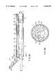
- FIG. 1is a side view showing an ultrasonic coagulating/cutting tool in an assembled state according to a first embodiment of the present invention
- FIG. 2Ais a side view showing a handle unit in the ultrasonic coagulating/cutting tool above;
- FIG. 2Bis a side view showing a probe unit in the ultrasonic coagulating/cutting tool above;
- FIG. 3is a side view showing a vibration unit in the ultrasonic coagulating/cutting tool above;
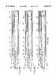
- FIG. 4Ais a longitudinal cross-section showing a distal end section of the ultrasonic coagulating/cutting tool
- FIG. 4Bis a transverse cross-section taken along line IVB--IVB in FIG. 4A;
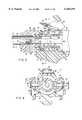
- FIG. 5is a longitudinal cross-section showing a base section of the ultrasonic coagulating/cutting tool above;
- FIG. 6is a transverse cross-section taken along line VI--VI in FIG. 5;
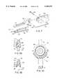
- FIG. 7is an expanded, perspective view showing a jaw section of the ultrasonic coagulating/cutting tool above;
- FIGS. 8A to 8Care a longitudinal cross-section showing a distal end section of the ultrasonic coagulating/cutting tool above;
- FIG. 9Ais a transverse cross-section taken along line IXA--IXA in FIG. 8B;
- FIG. 9Bis a transverse cross-section taken along line IVB--IVB in FIG. 8C;
- FIG. 10is a transverse cross-section taken along line X--X in FIG. 1;
- FIG. 11is a side view showing an ultrasonic coagulating/cutting tool in an assembled state according to a second embodiment of the present invention.
- FIG. 12is a perspective view showing a whole ultrasonic coagulating/cutting apparatus according to a third embodiment of the present invention.
- FIGS. 13A and 13Bare a side view for explaining the operation of a movable operation handle of the third embodiment
- FIG. 14is a side view showing a movable operation handle in a fourth embodiment of the present invention.
- FIGS. 15A and 15Bare a side view for explaining the operation of the movable operation handle in the fourth embodiment above.
- FIG. 1shows an assembled state of a so-called ultrasonic coagulating/cutting tool as an ultrasonic treating tool.
- the ultrasonic coagulating/cutting tool 1has a handle unit 2 as shown in FIG. 2A, a probe unit 3 as shown in FIG. 2B and a vibrating element unit 4 as shown in FIG. 3 and these units 2, 3 and 4 are assembled as shown in FIG. 1.
- the handle unit 2has an operation body section 12 equipped with a vibrating element connection section 11 as shown in FIG. 2A.
- the operation body section 12includes a fixed, lower-side handle (grip) 13 and a swingable upper-side handle (operation handle) 14.
- the lower handle 13is gripped by a hand palm as will be set out below.
- the lower-side handle 13has a finger-engaging ring 15 capable of inserting a hand's palm for finger grip.
- the finger-engaging ring 15allows a plurality of fingers, other than the thumb, to be selectively inserted therein.
- the upper-side handle 14has a thumb-engaging grip (thumb grip) section 14a for hand grip through a hand's palm.
- a thumb-engaging ring 16is provided at the thumb engaging section 14a.
- the upper-side handle 14is pivoted by shaft pins 17 threaded in the operation body section 12.
- the shaft pin 17is located further ahead of the position of the grip section of the lower-side handle 13 and the position of a force applying.
- point of the thumb-engaging section 14a of the upper-side handle 14is so located as to be displaced toward proximal side from a swinging center of the upper-side handle 14, that is, the grip section side, and its action direction is toward a substantially center of the operation section.
- abutting sections 18b and 18aare provided which are abutted together so as to restrict their end positions when the upper-side handle 14 is swung to a closing direction.
- fastening screw members 19are mounted on the base portion of the upper-side handle 14 and also serves as coupling members, that is, latching pins.
- the fastening screw member 19is inserted into an associated through hole 23 at a position displaced upwardly from, or near to, the shaft pin 17 for handle swinging action.
- engaging sections 21are provided at the inner ends of the fastening screw members 19 and adapted to engage a probe unit 3 mounted at the operation body 12.
- Operation knobs 22are formed on the fastening screw members 19 and positioned at the outer ends.
- the fastening screw members 19are inserted through the through holes 23 such that they are freely movable relative to the upper-side handle 14 in their axial direction.
- an externally threaded section 26is so formed as to be situated on the outer end side of the fastening screw member 19 and to be inserted into the internally threaded section 25 formed in the through hole 23.
- the fastening screw member 19has its intermediate section freely movable back and forth in a range situated in the through hole 23. For this reason, the engaging section 21 can be moved back to a disengaged position from a position in which the engaging section 21 is engaged with a later-described rotor and be moved forward to such an engaged position to allow the externally threaded section 26 of the fastening screw member 19 to be moved in the internally threaded section 25 to a fixed position.
- a coil spring 27is set relative to the associated fastening screw member 19.
- the coil spring 27acts in a way to enable the operation knob section 22 and the upper-side handle 14 to be urged away from each other.
- the fastening screw member 19is automatically moved back from the later-described rotor side under an elastic recovery force of the coil spring 27, so that it is possible to simply effect an insertion attachment of the probe unit 3 and its withdrawal detachment.
- a stopper piece 29is mounted as a detachable member above the operation body section 12 through a swing shaft 28.
- the stopper piece 29is used to fix, to a predetermined position, the vibration element unit 4 mounted on the operation body section 12.
- the stopper piece 29is so urged under a coil spring 30 around the swing arm 28 as to be swung to a direction in which it is latched to the vibrating element unit 4. Normally, the stopper piece 29 is swung to a position as shown in FIG. 5.
- insertion sheath section 31is so retained at the forward end section of the operation body section 12 as to be rotatable through the utilization of a rotation knob 32 and fixing nut 33.
- the insertion sheath section 31is fixedly mounted at the rotation knob 32 and the rotation knob 32 is mounted coaxial with the operation body section 12 in a way to be rotatable.
- a collar 34is provided on the operation body section 12 and sandwiched between the rotation knob 32 and the fixing nut 33 so that the rotation knob 32 is so retained as to be rotatable.
- some level of brakingis applied at all times to the insertion sheath section 31 through a force of friction of the rotation knob 32 against an associated member, so that the insertion sheath section 31 is not simply to rotate.
- the insertion sheath section 31is comprised of a double-tube structure comprising a core member 31a made of a rigid metal pipe and an outer covering 31b of an electrically insulating resin. Further, a pair of latching pieces 36 are provided, as shown in FIG. 4B, at a distal end section within the insertion sheath section 31. The distal end section of the probe unit 3 inserted in the insertion sheath section 31 is latched by the latching sheaths 36 to determine a rotation direction position of the probe unit 3 relative to the insertion sheath section 31.
- the latching piece 36is provided by extending one portion of a distal end portion of the core member 31a and inwardly bending this extending portion.
- An indicator 38is provided on the outer peripheral surface of the rotation knob 32 to indicate a latching position corresponding to the position of the latching piece 36.
- the vibrating element unit 4has the Langevin type ultrasonic vibration element 43 arranged in a cylindrical cover 42 serving also as a housing of the handpiece 41. And a horn 44 is connected to the forward end of the ultrasonic vibration element 43. As shown in FIG. 5, an internally threaded section 45 is provided at the forward end of the horn 44 to allow the rear end of the probe unit 3 to be threadably inserted.
- a ring-like stopper receiving member 56is provided at the forward end portion of the cylindrical cover 42.
- An annular circumferential groove 57is formed in and around the outer peripheral portion of the stopper receiving member 56.
- the forward end of the stopper piece 29 on the handle unit 2 sideis fitted in, and latched to, the outer peripheral groove 57 of the stopper receiving member 56.
- the rear end portion of a rotor 78 of the probe unit 3is fitted into an inner space 58 of the stopper receiving member 56.
- a long flexible handpiece cord 61is connected to the handpiece 41 and a handpiece plug 62 is provided at the extended end of the handpiece cord 61.
- a water-proof cap 63is attached to the handpiece plug 62. When the vibration element unit 4 is washed, the water-proof cap 63 covers the terminal and its neighborhood of the handpiece plug 62.
- a connection terminal 67is provided at the rear end of the handpiece 41 to allow the connection of a high-frequency cord at a time of treatment with a high-frequency.
- the probe unit 3has a rod-like long vibration transmitting member 71 for transmitting an ultrasonic vibration and a wire-like operation drive shaft (movable member) 72 arranged there along in a substantially parallel fashion.
- the vibration transmitting member 71is made of, for example, titanium material or aluminum material, which is high in sound effect and good in biocompatibility. Further, the vibration transmitting member 71 is comprised of, as shown in FIG. 2B, a forward-end side part 71a and a rear-end side part 71b, those parts being fixedly joined by screw-threading and bonding. An externally threaded section 73 is formed on the rear-end portion of the vibration transmitting member 71.
- the vibration transmitting member 71is coupled to the horn 44 by inserting the portion of the externally threaded section 73 into the internally threaded section 45 formed at the forward end of the horn 44. By effecting such insertion until a stepped end face 74 of the rear end of the vibration transmitting member 71 is brought to a position where it abuts against a forward end face of the horn 44, a strong connection is achieved between the vibration transmitting member 71 and the horn 44.
- a wrench-turning surface 75is formed at the outer peripheral surface of the rear end portion of the vibration transmitting member 71 so that it can be used at the attaching/detaching operation.
- the operation drive shaft 72is comprised of a wire-like member made of, for example, a stainless steel (SUS) material having a relative rigidness and spring elasticity.
- a thin metal pipe 76is fitted over the operation shaft 72 such that it extends from the basic end of the operation drive shaft 72 to an intermediate portion short of a distal end side.
- the rotor 78is fixedly mounted on the rear end portion of the operation drive shaft 72.
- the rotor 78is formed to a cylindrical rotor configuration with its center aligned with the center axis of the vibration transmitting member 71 in a concentric fashion.
- Two collars 81are provided on the outer peripheral surface of the rotor 78 with a latching annular groove 82 defined therebetween.
- O-rings 84, 84are mounted one after and one before the outer peripheral surface of the rotor 78.
- the forward end-side outer peripheral portion 85 of the rotor 78is fitted into a mating hole section 80 of the handle unit 2 and the rear end-side outer peripheral portion of the rotor 78 is fitted into the inner bore 58 of the stopper receiving member 56 in the inner bore of the operation body section 12.
- the stopper receiving piece 29is latched to the circumferential groove 57 of the vibration element unit 4-side stopper receiving member 56.
- the vibration element unit 4, together with the probe unit 3can be rotated as one unit.
- the operation drive shaft 72 of the probe unit 3 together with the rotor 78can be moved, in a back/forth axial direction, relative to a stationary member such as the vibration element unit 4 and vibration member 71.
- the vibration transmitting member 71 and the pipe 76 fitted over the operation drive shaft 72are mutually retained in place by a plurality of spacers 86.
- the respective vibration transmitting member 71is arranged in a position corresponding to a node of the vibration involved.
- the spacers 86retain the associated vibration transmitting member 71 and operation drive shaft 72 in a predetermined interval in a parallel array.
- the respective spacers 86 except a forwardmost spacer 86are so arranged that locating snap rings are fitted before and after each spacer on the pipe 76, that is, the pipe 76 fitted over the operation drive shaft 72, so as to inhibit the back/forth movement of the spacer 86.
- the respective locating snap ring 89is fixed to the outer peripheral surface of the pipe 76 by bonding.
- the forwardmost spacer 86is situated at the node of the ultrasonic vibration nearest to a remote end of the ultrasonic probe 115 as will be set out below.
- the forwardmost spacer 86may be fixed by bonding, etc., to the outer peripheral portion of the pipe 76 but, here, is loosely fitted over the outer peripheral surface of the pipe 76.
- the spacer 86has a support member 90 and the locating snap ring is fitted over both the spacer 86 and support member 90 and fastened thereover or fixed by bonding as one integral unit.
- the spacer 86 and support member 90are attached to a flange 95 section of the vibration transmitting member 90 and then the locating snap ring 91 is fitted over both the spacer 86 and support member 90, followed by the bonding of both the spacer 86 and locating snap ring 91.
- the support member 90is a member including the spacer 86.
- the above-mentioned swing restriction flange 95is provided on the outer peripheral portion of the vibration transmitting member 71 which is situated in the forwardmost spacer 86 position.
- the swing restriction flange 95is closely fitted into an associated groove in a corresponding inner surface portion of the spacer 86 to prevent the spacer 86 from being swung around the vibration transmitting member 71.
- a damping member 97made up of a vibration absorbing member, such as rubber, is situated on the operation drive shaft 72 side and fitted relative to the swing restriction flange 95.
- the forwardmost spacer 86serves also as a support portion of a jaw retaining member 100 extending forwardly of this position and both the spacer 86 and jaw retaining member 100 are formed as one integral unit.
- the jaw retaining member 100is supported by the spacer 86 and restricted from being moved in the axial direction of the vibration transmitting member 71 and around the axis.
- the jaw retaining member 100has its forward end extended immediately before the forward end of the vibration transmitting member 71 and has a slit groove 101 from near its base end to its forward end.
- a reinforcing bridge 102spans a lateral left/right portion of the slit groove 101.
- a jaw 105is pivotally mounted at and near the extending forward end of the jaw retaining member 100.
- a pivotally support pin 103is provided across the lateral left/right portion of the slit groove 101.
- the jaw 105is mounted around the pivotally supported pin 103.
- the jaw 105constitutes a so-called movable blade (movable-side grasping piece) which faces the ultrasonic probe 115 as will be set out below.
- the jaw 105comprises a body member 106 made of metal and grasping member 107 made of a resin.
- a shaft support coupling hole 108is formed near the base end of the body member 106.
- the coupling hole 108 for shaft supportconstitutes, as shown in FIG. 8A, an elongated hole diagonal relative to the axial direction of the insertion sheath section 31 and the pivotally support pin 103 is slidably inserted in the coupling hole 108.
- a connection hole 109is provided in the body member 106 near and below the coupling hole 108 so as to allow the forward end of the operation drive shaft 72 to be connected.
- the connection hole 109is provided across the lateral left/right section of the jaw 105.
- a bent section 110 of the operation drive shaft 72that is, a bent section obtained by bending the forward end portion of the operation drive shaft 72 at a substantially right angle, is inserted into the connection section 109.
- a fitting hole 111is provided in the body member 106 as a front/back direction elongated hole.
- a corresponding projection 112is closely fitted which is provided at the back surface of the grasping member 107.
- a collar 113is provided on left and right sides at a projecting end of the projection 112.
- the projection 112When the projection 112 is to be fitted into the fitting hole 111, it is done so by, as shown in FIG. 7, forcibly inserting, from below, the collars 113 of the projection into the fitting hole 111 in the body member 106 while elastically deforming the collars 113 and fitting hole 111. Then through the elastic deformation, the collars 113 pass through the fitting hole 111 and closely snap-fitted in the fitting hole 111. Further, the body member 106 is sandwiched between the back surface and collars 113 of the grasping member 107 and the grasping member 107 is retained in place on the body member 106.
- edges of the projection 112 and collars 113 involved when the projection 112 is fitted in the fitting hole 111are rounded/beveled as rounded or inclined sections 116 as shown in FIG. 9 and serve as guides when the projection 112 is fitted in the fitting hole 111.
- the grasping member 107is integrally formed as a slippery resin, such as polytetrafluoroethylene. Edge portions 118 are formed at the left and right edges of grasping surfaces 117 of the grasping member 107 and the tip of the edge portion 118 is serrated to provide toothed sections 119.
- the forward end portion of the vibration transmitting member 71constitutes an ultrasonic probe (fixed-side grasping piece) 115.
- the portion of the ultrasonic probe 115is so located as to face the grasping member 107 of the jaw 105. As shown in FIG. 9, the ultrasonic probe 115 is longer in vertical cross-section as shown in FIG. 9 and the outer peripheral surface portion of the ultrasonic probe 115 is sounded.
- an ultrasonic treating section 120is constituted by which a living tissue is grasped and coagulated/cut.
- a stopper mechanismis provided at a location of a jaw retaining member 100 and used to restrict a swing amount of the jaw 105 when the operation drive shaft 72 is so operated as to allow the jaw 105 to be closed. That is, as shown in FIG. 4A, a stopper tube (stopper body) 121 is fitted over an intermediate section of the operation drive shaft (movable member) 72 situated within the slit groove 101 of the jaw retaining member 100.
- the stopper tube 121has its internally threaded portion provided in its inner wall surface which is mated with an externally threaded section provided on the outer peripheral surface of the pipe 76 over which the operation drive shaft 72 is fitted. By doing so, these internally and externally threaded sections are so mated as to provide a fixedly mounted unit.
- a manufacturing/assembling meansis of a screw-threaded mating type, it is possible to fine adjust the position of the stopper tube 121 in its axial direction through a manufacturing/assembling process.
- a tube-like nut 122is threaded over the forward-end side of the outwardly threaded section of the pipe 76. Through the nut 122, it is possible to positively fix the stopper tube 121 by a double-nut system.
- a knurled sectionis formed, as a slippery stop section, on the outer peripheral surfaces of the stopper tube 121 and nut 122.
- the stopper tube 121 and nut 122after being adjusted in these positions, are threadedly mated with, or bonded and hence positively fixed, to the outer peripheral surface of the pipe 76.
- the above-mentioned stopper mechanismis such that, when the jaw 105 is closed by pulling back the operation drive shaft 72, a rear end 124 of the stopper tube 121 is abutted against a stopper receiving face 125 comprised of a rear end face of the slit groove 101 in the jaw retaining member 100 (stationary member), so that further pull-back of the operation drive shaft 72 is inhibited and hence an operation amount of the jaw 105 is restricted.
- the ultrasonic probe 115restricts an operation amount of the jaw 105 at a stage at which it is not worn deeply into contact with the body member 106.
- the lower-side handle 13 and upper-side handle 14are situated one at an upper side and one at a lower side as viewed on an extension center axis of the insertion sheath section 31.
- a finger contact section (finger engaging section) 13ais formed at the lower-side handle 13 (fixed side) to provide a grip section as a palm-grippable section.
- the longitudinal center axis of the grip section of the lower-side handle 13is substantially parallel to the longitudinal center axis of the vibration transmitting member 71 and insertion sheath section 31 through which the member 71 inserted.
- the finger engaging section 13a and thumb engaging section 14a of the lower-side handle 13 and upper-side handle 14are so formed as to be made somewhat broader than the external diameter of the cover (housing) 42 of the handpiece 41.
- the finger engaging section 13a and thumb engaging section 14aare so rounded as to hand-wrap the handpiece 41 portion from both above and below.
- the respective engaging sections 13a and 14a of the handles 13 and 14constitute parts of a substantially cylindrical configuration around the handpiece 41.
- the cover area of the handpiece 41is defined within a range of the finger engaging section 13a and thumb engaging section 14a and substantially covered with the finger engaging section 13a and thumb engaging section 14a.
- the fingers and thumb of the operatoris prevented from being directly contacted with the handpiece 41 and it is possible to avoid an inadvertent rotation of the vibration element unit 4. Since the widths of the finger engaging section 13a and thumb engaging section 14a are adequately greater, the palm-gripping and finger/thumb-gripping of the handles are soft to the touch and the operator experiences any pain during a prolonged time period of use, so that he or she suffers neither fatigue nor growing pain.
- the ultrasonic coagulating/cutting tool 1will be explained below.
- the ultrasonic element unit 4is assembled on the probe unit 3 and the assembly is inserted into the handle unit 2 as shown in FIG. 1.
- the grip section of the lower-side handle 13 in the handle unit 2is hand-gripped by the palm of one hand and the upper-side handle 14 is thumb-gripped by the thumb of the same hand.
- the ultrasonic coagulating/cutting tool 1is grasped as a whole.
- the insertion sheath section 31is guided into a body cavity by the use of a tracer, etc.
- the jaw 105 of the ultrasonic treating section 120can be opened/closed.
- a living tissueis grasped by them or, by the swing-open operation, an organ is separated or pushed aside.
- an ultrasonic vibrationis applied to the ultrasonic probe 115 while grasping the living tissue of a diseased region between the ultrasonic probe 115 and the jaw 105. By doing so, the grasped living tissue is coagulated/cut.
- the ultrasonic probe 115is elastically displaced under a pressure force from the jaw 105. That is, since the ultrasonic probe 115 is supported by the vibration transmitting member 71, the vibration transmitting member 71 is flexed at its free end portion and the ultrasonic probe 115 is displaced, while being pushed by the grasping surface 117 of the jaw 105, in a manner to follow that motion. And the living tissue is sandwiched with a proper grasping force and grasped by the jaw 105 and the ultrasonic probe 115 and coagulated/cut.
- FIG. 8Ashows a state in which the grasping surface 117 of the grasping member 107 of the jaw 105 is set in contact with the upper surface of the ultrasonic probe 115 and the ultrasonic probe 115 is in a not yet deformed state.
- FIG. 8Bshows a state in which the ultrasonic probe 115 is deformed by being pushed by the jaw 105 and displaced. This is a state in which ultrasonic treatment is made with the living tissue sandwiched between the jaw 105 and the ultrasonic probe 115.
- the jaw 105is swung through a given angle, then the above-mentioned stopper mechanism works and there is no further swing action and hence no excessive grasping force is applied to the ultrasonic probe 115.
- the ultrasonic probe 115When the living tissue portion has been cut between the jaw 105 and the ultrasonic probe 115, then the ultrasonic probe 115 while being vibrated is brought into contact with the grasping surface 117 of the grasping member 107 of the jaw 105 as shown in FIG. 9A. Each time the treatment of the living tissue is repeated, the grasping surface 117 of the grasping member 107 is worn little by little and a dent 123 is formed as shown in FIG. 9B. Before the dent 123 reaches the depth at which the body member 106 made of a metal is situated, the above-mentioned stopper mechanism works, so that the swinging motion of the jaw 105 is stopped.
- the operation final-end position of the jaw 105is restricted at a stage where the dent 123 never reaches a deep position at which the ultrasonic probe 115 is contacted with the body member 106 made of a metal. For this reason, even if the grasping member 107 is worn due to its contact with the ultrasonic probe 115, the body member 106 of the jaw 105 is maintained in an area not contacted with the ultrasonic probe 115, so that this prevents the contacting of the ultrasonic probe, in a vibration state, with a metal area.
- the ultrasonic probe 115 in a vibration stateis not contacted with the metal area, so that no damage is caused to the ultrasonic probe 115, etc., and hence there occurs no dull dissection of the living tissue. As a result, it ensures an adequately prolonged use of the ultrasonic coagulating/cutting tool and an enhanced endurance.
- the pressing contact of the jaw 105 with the ultrasonic probe 115is restricted by the above-mentioned stopper mechanism and an amount of grasping force is restricted within a proper range. Even if, therefore, the handles are gripped, for example, with a force as strong as practically possible or any excessive operation force is applied to the handles 13 and 14 though depending upon a difference, or extent of skill, in individual operators, it is possible to cut the living tissue, while coagulating it. Therefore, there is no risk that the living tissue such as a very small vessel in particular will be simply cut in a mechanical way.
- the coupling hole 108 through which the pin 103 pivoted to the jaw 105is elongated and its longitudinal direction is inclined relative to a line vertical to the grasping surface of the ultrasonic probe 115, so that the pivotally supported pin 103 is relatively movable in the coupling hole 108 in the jaw 105. For this reason, the mating of the jaw 105 with the ultrasonic probe 115 is improved and made uniform.
- the pivotally supported pin 103is situated at a lower end of the coupling hole 108 in the jaw 105 as shown in FIG. 8A.
- the jaw 105is further swung with the living tissue grasped, then the jaw 105 is pulled downward, so that the pin 103 slides up to the upper end of the coupling hole 108 as shown in FIG. 8B.
- the pin 103is slidable in the coupling hole 108 in the jaw 105 and hence the grasping surfaces of both are maintained in substantially parallel grasping state, so that the mating of both can be improved.
- the relation of the pivotally supported pin 103 and coupling hole 108 in the jaw 105may be formed with the pin 103 on the jaw 105 side and the coupling hole 108 on the jaw retaining member 100 side.
- the stopper mechanism for restricting the swinging amount of the jaw 105may be configured as follows. That is, it may comprise a connection member, such as a rotor 78, coupled to the rear end of the operation drive shaft 72 of the probe unit 3 and movement-operated by the handle operation on the handle unit 2 side and a fixed member confronting the rotor 78 and, when being viewed in a relative way, serving as a stationary member, in which the rear end of the rotor 78 collides against the front end of the stopper receiving member 56 to restrict the movement of the operation drive shaft 72 and, by doing so, restrict the open/close end position of the jaw 105 relative to the ultrasonic probe 115.
- a connection membersuch as a rotor 78
- the second embodimentconstitutes a variant of the handle unit 2.
- the handle unit (variant)is such that, instead of providing the finger engaging (grip) ring and thumb engaging ring to lower-and upper-end handles 13 and 14, a spring member 131 is provided between the lower-and upper-side handles 13 and 14 to urge the respective handles 13 and 14 away from each other.
- the spring member 131is comprised of a leaf spring, one end of which is mounted by a fastening means 132 to the inner surface of the lower-side handle 13 and the other end of which is joined to the inner surface of the upper-side handle 14.
- FIG 11shows a standby state in which the upper-side handle 14 is brought to an opened state under an urging force of the spring member 131.
- the handles 13 and 14is urged to a normally open state and it is not necessary to provide any finger engaging rings.
- the other arrangement of these handles 13 and 14is similar to the above-mentioned first embodiment.
- abutting faces 135, 136are provided on the base portions of the lower-and corresponding upper-side handles 13 and 14. These abutting faces 135 and 136 provide a stopper mechanism for restricting a swinging amount of the jaw 105. How to restrict the swinging amount of the jaw 105 is the same as that of the first embodiment.
- stopper mechanism of the first embodiment of the present inventionsuch stopper mechanism may be provided.
- the stopper mechanism of the first embodimentacts as a main mechanism and that of the second embodiment as a subsidiary mechanism.
- FIGS. 12 and 13show a third embodiment of the present invention.
- FIG. 12is a perspective view showing a whole structure of an ultrasonic coagulating/cutting apparatus.
- the ultrasonic coagulating/cutting apparatus 141comprises an operation section 142, insertion section 143 so provided as to be connected to the operation section 142, and treating section 144 provided as a clamping section at a distal end of the insertion section 143.
- a gripping section 145is adapted to be hand-gripped by one hand's four fingers of the operator and used to hold the operation section 142.
- a sheath 147is provided at the front-end side portion of the gripping section 145 and constitutes the insertion section 143 through a rotation knob 146.
- a vibration transmitting member 148 for transmitting an ultrasonic vibration to a distal end-side probe and an operation line 149 for operating the clamping memberare inserted into the sheath 147.
- a fixed edge (probe) 150 and movable edge (clamping member) 151are provided at the distal end of the sheath 147, the fixed edge being formed by a forward end of an extension of the vibration transmitting member 148 and the movable edge being operated by the operation line.
- the movable blade 151is pivoted to a jaw retaining member 152 which is fitted in the distal end portion of the sheath 147.
- the movable blade 151is swung by the operation of the operation line 149 which is moved in a back/forth direction. And the movable blade is opened and closed by being moved toward and away from the fixed blade 150 which is ultrasonically vibrated.
- the fixed blade 150 and movable blade 151constitute the treating section 144 serving as a clamping section for clamping a living tissue of interest.
- the operation section 142includes an ultrasonic vibration element (not shown) covered with a vibration element cover 153 of a cylindrical configuration. By doing so, an ultrasonic vibration element unit is constituted with the vibration element cover 153 as a body section. An ultrasonic vibration is generated at the ultrasonic vibration element of the ultrasonic vibration element unit and transmitted through the vibration transmitting member 148 to the fixed edge (probe) 150.
- the grip section 145is so formed as to have a lower surface portion of the vibration element cover 153 covered therewith along the vibration cover 153.
- the grip section 145serves also as the fixed handle of a handle section and the finger-gripping (finger-engaging section) of the grip section 145 is formed parallel to, and along, the vibration element cover 153 of the operation section 142.
- the portion of the gripping section 145is finger-gripped by one hand and the operation section 142 can be held by one hand.
- the body section of the operation section 142is situated between the grip section 145 and a movable operation handle 154 and the vibration element cover (body section) 153 is located in an operator-hand's palm with which the gripping section 145 is gripped.
- the gripping section 145together with a later-described movable operation handle 154, constitutes a handle unit.
- the handle unitis detachably mounted on the ultrasonic vibration element unit and fixed to the ultrasonic vibration element unit by the use of a stopper piece 159.
- the movable operation handle 154is swingable about a fulcrum P situated at the forward end portion of the gripping section 145 and, at a power application end portion (point) of the movable operation handle 154, the shaft portion of a latching knob 155 is rotatably mounted such that it extends through the power application end point.
- a latching claw(not shown) is provided at an inner end of the shaft portion of the latching knob 155.
- the latching clawis fitted in, and latched to, a circumferential groove in a rotor (not shown) to which the rear end of the operation rod 149 is attached.
- An externally threaded sectionis provided on the shaft section of the latching knob 155 such that it is mated with an internally threaded section in a through hole in the movable operation handle 154.
- a thumb engaging section 158 situated at an operation force application point of the movable operation handle 154is engaged by the thumb 156 of the operator's hand with which the gripping section 145 is gripped.
- a shippery-preventing ribs 157are provided on the surface of the thumb engaging section 158.
- the operation force application point of the movable operation handle 154is located more on the proximal end side than its swing center. The direction in which a force acts on the operation force application point is toward or away from the gripping section 145.
- the force application point on which the operator's thumb 156 operates the movable operation handle 154is located more on the gripping section 145 side of the operation section 142 than at a rotation center of the movable operation handle 154 and this structure is such that the direction in which such a force acts is toward and away from a substantially center of the body section. Further, in this embodiment, the direction in which a force applied by the thumb gripped on the movable operation handle 154 is toward or away from the gripping section 145.
- the gripping section 145is gripped by four fingers of one hand and, by doing so, the operation section 142 is held.
- the thumb engaging section 158 of the movable operation handle 154is engaged by the thumb of the same hand.
- the movable operation handle 154is raised in a direction of an arrow in FIG. 13B, the movable operation handle 154 is swung about a swing fulcrum P and, through the operation line 149, the movable edge 151 is opened relative to the fixed edge 150.
- the movable edge 151 and fixed edge 150are set in a manner to sandwich the living tissue therebetween and, when the thumb engaging section 158 of the movable operation handle 154 is thumb-depressed in a direction as indicated by an arrow in FIG. 13A, the movable edge 151 is closed through the operation line 149.
- the ultrasonic vibration elementWhen the ultrasonic vibration element is vibrated, it is transmitted through a vibration transmitting member 148 to the fixed edge 150 of a probe and, through the vibration of the fixed edge 150, the living tissue is coagulated/cut.
- the sheath 147, fixed edge 150 and movable edge 151are rotated as one unit about the center axis of the fixed edge 150 and vibration element cover 153 in a manner to follow the rotation of the rotation knob 146.
- FIG. 14shows a fourth embodiment of the present invention with similar reference numerals employed to designate similar parts or elements corresponding to those shown in the above-mentioned third embodiment and further explanation omitted.
- an elastic body 161is provided at a location between a vibration element cover 153 and a thumb engaging section 158 and comprised of a unshaped leaf spring. And a movable edge 151 is elastically urged by the elastic body 161 in a direction in which the movable edge 151 is opened, that is, elastically urged with the movable operation handle 154 outward.
- the thumb engaging section 158is moved, by an elastic force of the elastic body 161, in a direction away from the vibration element cover 153 and, in that direction, the movable operation handle 154 is swung, thus allowing the movable edge 151 to be automatically opened.
- FIGS. 15A and 15Bshow a fifth embodiment of the present embodiment with similar reference numerals employed to designate parts or elements corresponding to those shown in the above-mentioned third embodiment and further explanation omitted.
- a second finger engaging section 160is provided continuous with the movable operation handle 154 in a manner to extend downward relative to the gripping section 145.
- the rotation radius of the second finger engaging section 160is shorter than that of a thumb engaging section 158.
- a movable edge 151is closed by depressing the first thumb engaging section 158 by an operator's thumb 156.
- the second finger engaging section 160is engaged by a forefinger 162 of an operator and pulled toward the operator side so that a movable edge 151 is opened.
- a gripping section 145 of an ultrasonic coagulating/cutting device 141can be palm-gripped as a whole and a fixed edge 150 and movable edge 151 at a distal end of a sheath 147 are not vibrated. And a full concentration can be paid to the operation of the movable operation handle 154, so that a delicate operation can be done at a time of coagulation/cutting.
- the center axis of the operation section 142corresponds to the center of finger gripping and the body section of the operation section 142 is located between the gripping section 145 and the movable operation handle 154. Therefore, the variable operation handle 154 can be operated while gripping the operation section 142 in a stabler state. As a result, an insertion section 142 is less likely to be vibrated during operation.
- the movable edge 151is opened by pulling the forefinger 162 toward the operator.
- a readier operationis ensured at a time of opening the movable edge 151 and there is less fatigue on the thumb of the operator. Since the swing radius of the second finger engaging section 160 is shorter than that of the first thumb engaging section 158, the opening speed of the movable edge 151 is quickened and the quick separation of the living tissue can be done in a stable fashion. Thus, the separation of minute tissue of interest can be performed in an effective way.
- a tissue separation operationcan be readily carried out by the repeated seasaw motion of the thumb engaging section 158 and finger engaging section 160.
- thumb engaging section 158 and finger engaging section 160are not of a ring type and there is neither fatigue nor numbness on the thumb and fingers of the operator during the operation of long duration.
- a handle unitsuch as the gripping section 145 and movable operation handle is constructed as separate from the ultrasonic vibration element unit, both may be assembled as an integral unit.
- the gripping section 145 and movable operation handle 154may be provided directly on the body section of the operation section 142.
Landscapes
- Health & Medical Sciences (AREA)
- Surgery (AREA)
- Engineering & Computer Science (AREA)
- Life Sciences & Earth Sciences (AREA)
- Heart & Thoracic Surgery (AREA)
- Nuclear Medicine, Radiotherapy & Molecular Imaging (AREA)
- Mechanical Engineering (AREA)
- Biomedical Technology (AREA)
- Dentistry (AREA)
- Medical Informatics (AREA)
- Molecular Biology (AREA)
- Animal Behavior & Ethology (AREA)
- General Health & Medical Sciences (AREA)
- Public Health (AREA)
- Veterinary Medicine (AREA)
- Surgical Instruments (AREA)
Abstract
Description
Claims (11)
Applications Claiming Priority (6)
| Application Number | Priority Date | Filing Date | Title |
|---|---|---|---|
| JP14750298 | 1998-05-28 | ||
| JP10-147502 | 1998-05-28 | ||
| JP10-308600 | 1998-10-29 | ||
| JP30860098AJP3791875B2 (en) | 1998-10-29 | 1998-10-29 | Ultrasonic treatment device |
| JP00931299AJP3782598B2 (en) | 1998-05-28 | 1999-01-18 | Ultrasonic coagulation and incision device |
| JP11-009312 | 1999-01-18 |
Publications (1)
| Publication Number | Publication Date |
|---|---|
| US6165191Atrue US6165191A (en) | 2000-12-26 |
Family
ID=27278433
Family Applications (1)
| Application Number | Title | Priority Date | Filing Date |
|---|---|---|---|
| US09/318,053Expired - LifetimeUS6165191A (en) | 1998-05-28 | 1999-05-25 | Ultrasonic treating tool |
Country Status (1)
| Country | Link |
|---|---|
| US (1) | US6165191A (en) |
Cited By (78)
| Publication number | Priority date | Publication date | Assignee | Title |
|---|---|---|---|---|
| US20020165577A1 (en)* | 2001-05-04 | 2002-11-07 | Ethicon Endo-Surgery, Inc. | Easily detachable ultrasonic clamping device |
| US20030032899A1 (en)* | 2001-07-26 | 2003-02-13 | Matsushita Electric Works, Ltd. | Ultrasonic cosmetic device |
| US6783524B2 (en) | 2001-04-19 | 2004-08-31 | Intuitive Surgical, Inc. | Robotic surgical tool with ultrasound cauterizing and cutting instrument |
| US20040193199A1 (en)* | 2003-01-06 | 2004-09-30 | Olympus Corporation | Ultrasonic treatment device |
| US20040199194A1 (en)* | 2001-12-18 | 2004-10-07 | Witt David A. | Curved clamp arm tissue pad attachment for use with ultrasonic surgical instruments |
| DE10320412A1 (en)* | 2003-05-07 | 2004-11-25 | Berchtold Holding Gmbh | Ultrasonic surgical scissor shank incorporates groove limited at both ends for insertion of a removable clamping block |
| US20060264750A1 (en)* | 2004-01-13 | 2006-11-23 | Olympus Corporation | Ultrasonic treatment apparatus |
| US20070043297A1 (en)* | 2005-08-19 | 2007-02-22 | Olympus Medical Systems Corp. | Ultrasonic coagulation and cutting apparatus |
| US7695485B2 (en) | 2001-11-30 | 2010-04-13 | Power Medical Interventions, Llc | Surgical device |
| US7743960B2 (en) | 2002-06-14 | 2010-06-29 | Power Medical Interventions, Llc | Surgical device |
| US20100179457A1 (en)* | 2008-07-08 | 2010-07-15 | Blaine Laboratories, Inc. | Vibrating anesthesia device |
| US7918230B2 (en) | 2007-09-21 | 2011-04-05 | Tyco Healthcare Group Lp | Surgical device having a rotatable jaw portion |
| US7963433B2 (en) | 2007-09-21 | 2011-06-21 | Tyco Healthcare Group Lp | Surgical device having multiple drivers |
| US8016855B2 (en) | 2002-01-08 | 2011-09-13 | Tyco Healthcare Group Lp | Surgical device |
| US8025199B2 (en) | 2004-02-23 | 2011-09-27 | Tyco Healthcare Group Lp | Surgical cutting and stapling device |
| WO2012061645A1 (en)* | 2010-11-05 | 2012-05-10 | Ethicon Endo-Surgery, Inc. | Surgical instrument with modular end effector |
| EP2474280A4 (en)* | 2010-01-21 | 2012-08-29 | Olympus Medical Systems Corp | SURGICAL TREATMENT DEVICE |
| US8292888B2 (en) | 2001-04-20 | 2012-10-23 | Tyco Healthcare Group Lp | Bipolar or ultrasonic surgical device |
| US9000720B2 (en) | 2010-11-05 | 2015-04-07 | Ethicon Endo-Surgery, Inc. | Medical device packaging with charging interface |
| US8998939B2 (en) | 2010-11-05 | 2015-04-07 | Ethicon Endo-Surgery, Inc. | Surgical instrument with modular end effector |
| US9011471B2 (en) | 2010-11-05 | 2015-04-21 | Ethicon Endo-Surgery, Inc. | Surgical instrument with pivoting coupling to modular shaft and end effector |
| US9011427B2 (en) | 2010-11-05 | 2015-04-21 | Ethicon Endo-Surgery, Inc. | Surgical instrument safety glasses |
| US9017849B2 (en) | 2010-11-05 | 2015-04-28 | Ethicon Endo-Surgery, Inc. | Power source management for medical device |
| US9017851B2 (en) | 2010-11-05 | 2015-04-28 | Ethicon Endo-Surgery, Inc. | Sterile housing for non-sterile medical device component |
| US9039720B2 (en) | 2010-11-05 | 2015-05-26 | Ethicon Endo-Surgery, Inc. | Surgical instrument with ratcheting rotatable shaft |
| US9089338B2 (en) | 2010-11-05 | 2015-07-28 | Ethicon Endo-Surgery, Inc. | Medical device packaging with window for insertion of reusable component |
| US9113878B2 (en) | 2002-01-08 | 2015-08-25 | Covidien Lp | Pinion clip for right angle linear cutter |
| US9161803B2 (en) | 2010-11-05 | 2015-10-20 | Ethicon Endo-Surgery, Inc. | Motor driven electrosurgical device with mechanical and electrical feedback |
| US9247986B2 (en) | 2010-11-05 | 2016-02-02 | Ethicon Endo-Surgery, Llc | Surgical instrument with ultrasonic transducer having integral switches |
| CN105682588A (en)* | 2014-04-15 | 2016-06-15 | 奥林巴斯株式会社 | Energy treatment instrument |
| US9375255B2 (en) | 2010-11-05 | 2016-06-28 | Ethicon Endo-Surgery, Llc | Surgical instrument handpiece with resiliently biased coupling to modular shaft and end effector |
| US9381058B2 (en) | 2010-11-05 | 2016-07-05 | Ethicon Endo-Surgery, Llc | Recharge system for medical devices |
| US9421062B2 (en) | 2010-11-05 | 2016-08-23 | Ethicon Endo-Surgery, Llc | Surgical instrument shaft with resiliently biased coupling to handpiece |
| US9526921B2 (en) | 2010-11-05 | 2016-12-27 | Ethicon Endo-Surgery, Llc | User feedback through end effector of surgical instrument |
| US9597143B2 (en) | 2010-11-05 | 2017-03-21 | Ethicon Endo-Surgery, Llc | Sterile medical instrument charging device |
| WO2017066088A1 (en)* | 2015-10-16 | 2017-04-20 | Ethicon Endo-Surgery, Llc | Ultrasonic surgical instrument with removable shaft assembly portion |
| US9649150B2 (en) | 2010-11-05 | 2017-05-16 | Ethicon Endo-Surgery, Llc | Selective activation of electronic components in medical device |
| US9782215B2 (en) | 2010-11-05 | 2017-10-10 | Ethicon Endo-Surgery, Llc | Surgical instrument with ultrasonic transducer having integral switches |
| US9782214B2 (en) | 2010-11-05 | 2017-10-10 | Ethicon Llc | Surgical instrument with sensor and powered control |
| US20180000507A1 (en)* | 2015-06-17 | 2018-01-04 | Olympus Corporation | Surgical instrument and surgical instrument unit |
| US9901359B2 (en) | 2004-10-08 | 2018-02-27 | Ethicon Llc | Actuation mechanism for use with an ultrasonic surgical instrument |
| US10085792B2 (en) | 2010-11-05 | 2018-10-02 | Ethicon Llc | Surgical instrument with motorized attachment feature |
| US10136938B2 (en) | 2014-10-29 | 2018-11-27 | Ethicon Llc | Electrosurgical instrument with sensor |
| US10172684B2 (en) | 2016-04-29 | 2019-01-08 | Ethicon Llc | Lifecycle monitoring features for surgical instrument |
| US10420580B2 (en) | 2016-08-25 | 2019-09-24 | Ethicon Llc | Ultrasonic transducer for surgical instrument |
| US10433865B2 (en) | 2007-11-30 | 2019-10-08 | Ethicon Llc | Ultrasonic surgical blades |
| US10441308B2 (en) | 2007-11-30 | 2019-10-15 | Ethicon Llc | Ultrasonic surgical instrument blades |
| US10531910B2 (en) | 2007-07-27 | 2020-01-14 | Ethicon Llc | Surgical instruments |
| US10537380B2 (en) | 2010-11-05 | 2020-01-21 | Ethicon Llc | Surgical instrument with charging station and wireless communication |
| US10603064B2 (en) | 2016-11-28 | 2020-03-31 | Ethicon Llc | Ultrasonic transducer |
| US10660695B2 (en) | 2010-11-05 | 2020-05-26 | Ethicon Llc | Sterile medical instrument charging device |
| US10709906B2 (en) | 2009-05-20 | 2020-07-14 | Ethicon Llc | Coupling arrangements and methods for attaching tools to ultrasonic surgical instruments |
| US10722261B2 (en) | 2007-03-22 | 2020-07-28 | Ethicon Llc | Surgical instruments |
| US10779848B2 (en) | 2006-01-20 | 2020-09-22 | Ethicon Llc | Ultrasound medical instrument having a medical ultrasonic blade |
| US10820920B2 (en) | 2017-07-05 | 2020-11-03 | Ethicon Llc | Reusable ultrasonic medical devices and methods of their use |
| US10828057B2 (en) | 2007-03-22 | 2020-11-10 | Ethicon Llc | Ultrasonic surgical instruments |
| US10828059B2 (en) | 2007-10-05 | 2020-11-10 | Ethicon Llc | Ergonomic surgical instruments |
| US10835768B2 (en) | 2010-02-11 | 2020-11-17 | Ethicon Llc | Dual purpose surgical instrument for cutting and coagulating tissue |
| US10842580B2 (en) | 2012-06-29 | 2020-11-24 | Ethicon Llc | Ultrasonic surgical instruments with control mechanisms |
| US10842522B2 (en) | 2016-07-15 | 2020-11-24 | Ethicon Llc | Ultrasonic surgical instruments having offset blades |
| US10856896B2 (en) | 2005-10-14 | 2020-12-08 | Ethicon Llc | Ultrasonic device for cutting and coagulating |
| US10874418B2 (en) | 2004-02-27 | 2020-12-29 | Ethicon Llc | Ultrasonic surgical shears and method for sealing a blood vessel using same |
| US10881448B2 (en) | 2010-11-05 | 2021-01-05 | Ethicon Llc | Cam driven coupling between ultrasonic transducer and waveguide in surgical instrument |
| US10893883B2 (en) | 2016-07-13 | 2021-01-19 | Ethicon Llc | Ultrasonic assembly for use with ultrasonic surgical instruments |
| US10952759B2 (en) | 2016-08-25 | 2021-03-23 | Ethicon Llc | Tissue loading of a surgical instrument |
| US10959769B2 (en) | 2010-11-05 | 2021-03-30 | Ethicon Llc | Surgical instrument with slip ring assembly to power ultrasonic transducer |
| US10966744B2 (en) | 2016-07-12 | 2021-04-06 | Ethicon Llc | Ultrasonic surgical instrument with piezoelectric central lumen transducer |
| US10973563B2 (en) | 2010-11-05 | 2021-04-13 | Ethicon Llc | Surgical instrument with charging devices |
| US11020140B2 (en) | 2015-06-17 | 2021-06-01 | Cilag Gmbh International | Ultrasonic surgical blade for use with ultrasonic surgical instruments |
| US11033292B2 (en) | 2013-12-16 | 2021-06-15 | Cilag Gmbh International | Medical device |
| USD924400S1 (en) | 2016-08-16 | 2021-07-06 | Cilag Gmbh International | Surgical instrument |
| US11058447B2 (en) | 2007-07-31 | 2021-07-13 | Cilag Gmbh International | Temperature controlled ultrasonic surgical instruments |
| US11272952B2 (en) | 2013-03-14 | 2022-03-15 | Cilag Gmbh International | Mechanical fasteners for use with surgical energy devices |
| US11369402B2 (en) | 2010-02-11 | 2022-06-28 | Cilag Gmbh International | Control systems for ultrasonically powered surgical instruments |
| US11553954B2 (en) | 2015-06-30 | 2023-01-17 | Cilag Gmbh International | Translatable outer tube for sealing using shielded lap chole dissector |
| US11666784B2 (en) | 2007-07-31 | 2023-06-06 | Cilag Gmbh International | Surgical instruments |
| US11690641B2 (en) | 2007-07-27 | 2023-07-04 | Cilag Gmbh International | Ultrasonic end effectors with increased active length |
| US11877734B2 (en) | 2007-07-31 | 2024-01-23 | Cilag Gmbh International | Ultrasonic surgical instruments |
Citations (4)
| Publication number | Priority date | Publication date | Assignee | Title |
|---|---|---|---|---|
| US5322055A (en)* | 1993-01-27 | 1994-06-21 | Ultracision, Inc. | Clamp coagulator/cutting system for ultrasonic surgical instruments |
| US5906628A (en)* | 1996-06-26 | 1999-05-25 | Olympus Optical Co., Ltd. | Ultrasonic treatment instrument |
| US5980510A (en)* | 1997-10-10 | 1999-11-09 | Ethicon Endo-Surgery, Inc. | Ultrasonic clamp coagulator apparatus having improved clamp arm pivot mount |
| US6063050A (en)* | 1996-10-04 | 2000-05-16 | United States Surgical Corp. | Ultrasonic dissection and coagulation system |
- 1999
- 1999-05-25USUS09/318,053patent/US6165191A/ennot_activeExpired - Lifetime
Patent Citations (5)
| Publication number | Priority date | Publication date | Assignee | Title |
|---|---|---|---|---|
| US5322055A (en)* | 1993-01-27 | 1994-06-21 | Ultracision, Inc. | Clamp coagulator/cutting system for ultrasonic surgical instruments |
| US5322055B1 (en)* | 1993-01-27 | 1997-10-14 | Ultracision Inc | Clamp coagulator/cutting system for ultrasonic surgical instruments |
| US5906628A (en)* | 1996-06-26 | 1999-05-25 | Olympus Optical Co., Ltd. | Ultrasonic treatment instrument |
| US6063050A (en)* | 1996-10-04 | 2000-05-16 | United States Surgical Corp. | Ultrasonic dissection and coagulation system |
| US5980510A (en)* | 1997-10-10 | 1999-11-09 | Ethicon Endo-Surgery, Inc. | Ultrasonic clamp coagulator apparatus having improved clamp arm pivot mount |
Cited By (160)
| Publication number | Priority date | Publication date | Assignee | Title |
|---|---|---|---|---|
| US9662514B2 (en) | 1999-06-02 | 2017-05-30 | Covidien Lp | Bipolar or ultrasonic surgical device |
| US9247940B2 (en) | 1999-06-02 | 2016-02-02 | Covidien Lp | Surgical cutting and stapling device |
| US10335143B2 (en) | 1999-06-02 | 2019-07-02 | Covidien Lp | Surgical cutting and stapling device |
| US9078654B2 (en) | 1999-06-02 | 2015-07-14 | Covidien Lp | Surgical device |
| US6783524B2 (en) | 2001-04-19 | 2004-08-31 | Intuitive Surgical, Inc. | Robotic surgical tool with ultrasound cauterizing and cutting instrument |
| US8845665B2 (en) | 2001-04-20 | 2014-09-30 | Covidien Lp | Bipolar or ultrasonic surgical device |
| US8523890B2 (en) | 2001-04-20 | 2013-09-03 | Covidien Lp | Bipolar or ultrasonic surgical device |
| US8292888B2 (en) | 2001-04-20 | 2012-10-23 | Tyco Healthcare Group Lp | Bipolar or ultrasonic surgical device |
| US20020165577A1 (en)* | 2001-05-04 | 2002-11-07 | Ethicon Endo-Surgery, Inc. | Easily detachable ultrasonic clamping device |
| US20030032899A1 (en)* | 2001-07-26 | 2003-02-13 | Matsushita Electric Works, Ltd. | Ultrasonic cosmetic device |
| US8021373B2 (en) | 2001-11-30 | 2011-09-20 | Tyco Healthcare Group Lp | Surgical device |
| US7695485B2 (en) | 2001-11-30 | 2010-04-13 | Power Medical Interventions, Llc | Surgical device |
| US8740932B2 (en) | 2001-11-30 | 2014-06-03 | Covidien Lp | Surgical device |
| US8512359B2 (en) | 2001-11-30 | 2013-08-20 | Covidien Lp | Surgical device |
| US20040199194A1 (en)* | 2001-12-18 | 2004-10-07 | Witt David A. | Curved clamp arm tissue pad attachment for use with ultrasonic surgical instruments |
| US9113878B2 (en) | 2002-01-08 | 2015-08-25 | Covidien Lp | Pinion clip for right angle linear cutter |
| US8858589B2 (en) | 2002-01-08 | 2014-10-14 | Covidien Lp | Surgical device |
| US8016855B2 (en) | 2002-01-08 | 2011-09-13 | Tyco Healthcare Group Lp | Surgical device |
| US8518074B2 (en) | 2002-01-08 | 2013-08-27 | Covidien Lp | Surgical device |
| US9861362B2 (en) | 2002-06-14 | 2018-01-09 | Covidien Lp | Surgical device |
| US8056786B2 (en) | 2002-06-14 | 2011-11-15 | Tyco Healthcare Group Lp | Surgical device |
| US7743960B2 (en) | 2002-06-14 | 2010-06-29 | Power Medical Interventions, Llc | Surgical device |
| US8540733B2 (en) | 2002-06-14 | 2013-09-24 | Covidien Lp | Surgical method and device having a first jaw and a second jaw in opposed correspondence for clamping, cutting, and stapling tissue |
| US7563269B2 (en)* | 2003-01-06 | 2009-07-21 | Olympus Corporation | Ultrasonic treatment device |
| US20040193199A1 (en)* | 2003-01-06 | 2004-09-30 | Olympus Corporation | Ultrasonic treatment device |
| DE10320412A1 (en)* | 2003-05-07 | 2004-11-25 | Berchtold Holding Gmbh | Ultrasonic surgical scissor shank incorporates groove limited at both ends for insertion of a removable clamping block |
| US7837699B2 (en)* | 2004-01-13 | 2010-11-23 | Olympus Corporation | Ultrasonic treatment apparatus |
| US20060264750A1 (en)* | 2004-01-13 | 2006-11-23 | Olympus Corporation | Ultrasonic treatment apparatus |
| US8025199B2 (en) | 2004-02-23 | 2011-09-27 | Tyco Healthcare Group Lp | Surgical cutting and stapling device |
| US11219452B2 (en) | 2004-02-23 | 2022-01-11 | Covidien Lp | Surgical cutting and stapling device |
| US11730507B2 (en) | 2004-02-27 | 2023-08-22 | Cilag Gmbh International | Ultrasonic surgical shears and method for sealing a blood vessel using same |
| US10874418B2 (en) | 2004-02-27 | 2020-12-29 | Ethicon Llc | Ultrasonic surgical shears and method for sealing a blood vessel using same |
| US10537352B2 (en)* | 2004-10-08 | 2020-01-21 | Ethicon Llc | Tissue pads for use with surgical instruments |
| US20200323551A1 (en)* | 2004-10-08 | 2020-10-15 | Ethicon Llc | Actuation mechanism for use with an ultrasonic surgical instrument |
| US9901359B2 (en) | 2004-10-08 | 2018-02-27 | Ethicon Llc | Actuation mechanism for use with an ultrasonic surgical instrument |
| US11006971B2 (en) | 2004-10-08 | 2021-05-18 | Ethicon Llc | Actuation mechanism for use with an ultrasonic surgical instrument |
| US20070043297A1 (en)* | 2005-08-19 | 2007-02-22 | Olympus Medical Systems Corp. | Ultrasonic coagulation and cutting apparatus |
| US7717915B2 (en)* | 2005-08-19 | 2010-05-18 | Olympus Medical Systems Corporation | Ultrasonic coagulation and cutting apparatus |
| US11998229B2 (en) | 2005-10-14 | 2024-06-04 | Cilag Gmbh International | Ultrasonic device for cutting and coagulating |
| US10856896B2 (en) | 2005-10-14 | 2020-12-08 | Ethicon Llc | Ultrasonic device for cutting and coagulating |
| US10779848B2 (en) | 2006-01-20 | 2020-09-22 | Ethicon Llc | Ultrasound medical instrument having a medical ultrasonic blade |
| US12042168B2 (en) | 2006-01-20 | 2024-07-23 | Cilag Gmbh International | Ultrasound medical instrument having a medical ultrasonic blade |
| US10828057B2 (en) | 2007-03-22 | 2020-11-10 | Ethicon Llc | Ultrasonic surgical instruments |
| US10722261B2 (en) | 2007-03-22 | 2020-07-28 | Ethicon Llc | Surgical instruments |
| US11690641B2 (en) | 2007-07-27 | 2023-07-04 | Cilag Gmbh International | Ultrasonic end effectors with increased active length |
| US11607268B2 (en) | 2007-07-27 | 2023-03-21 | Cilag Gmbh International | Surgical instruments |
| US10531910B2 (en) | 2007-07-27 | 2020-01-14 | Ethicon Llc | Surgical instruments |
| US12324602B2 (en) | 2007-07-27 | 2025-06-10 | Cilag Gmbh International | Ultrasonic end effectors with increased active length |
| US11877734B2 (en) | 2007-07-31 | 2024-01-23 | Cilag Gmbh International | Ultrasonic surgical instruments |
| US11666784B2 (en) | 2007-07-31 | 2023-06-06 | Cilag Gmbh International | Surgical instruments |
| US12220143B2 (en) | 2007-07-31 | 2025-02-11 | Cilag Gmbh International | Temperature controlled ultrasonic surgical instruments |
| US11058447B2 (en) | 2007-07-31 | 2021-07-13 | Cilag Gmbh International | Temperature controlled ultrasonic surgical instruments |
| US12268900B2 (en) | 2007-07-31 | 2025-04-08 | Cilag Gmbh International | Surgical instruments |
| US7963433B2 (en) | 2007-09-21 | 2011-06-21 | Tyco Healthcare Group Lp | Surgical device having multiple drivers |
| US9017371B2 (en) | 2007-09-21 | 2015-04-28 | Covidien Lp | Surgical device having multiple drivers |
| US10420548B2 (en) | 2007-09-21 | 2019-09-24 | Covidien Lp | Surgical device having multiple drivers |
| US8752748B2 (en) | 2007-09-21 | 2014-06-17 | Covidien Lp | Surgical device having a rotatable jaw portion |
| US9282961B2 (en) | 2007-09-21 | 2016-03-15 | Covidien Lp | Surgical device having multiple drivers |
| US8353440B2 (en) | 2007-09-21 | 2013-01-15 | Covidien Lp | Surgical device having a rotatable jaw portion |
| US11317909B2 (en) | 2007-09-21 | 2022-05-03 | Covidien Lp | Surgical device having multiple drivers |
| US8272554B2 (en) | 2007-09-21 | 2012-09-25 | Tyco Healthcare Group Lp | Surgical device having multiple drivers |
| US7918230B2 (en) | 2007-09-21 | 2011-04-05 | Tyco Healthcare Group Lp | Surgical device having a rotatable jaw portion |
| US10117651B2 (en) | 2007-09-21 | 2018-11-06 | Covidien Lp | Surgical device having a rotatable jaw portion |
| US8342379B2 (en) | 2007-09-21 | 2013-01-01 | Covidien Lp | Surgical device having multiple drivers |
| US10881397B2 (en) | 2007-09-21 | 2021-01-05 | Covidien Lp | Surgical device having a rotatable jaw portion |
| US9204877B2 (en) | 2007-09-21 | 2015-12-08 | Covidien Lp | Surgical device having a rotatable jaw portion |
| US7992758B2 (en) | 2007-09-21 | 2011-08-09 | Tyco Healthcare Group Lp | Surgical device having a rotatable jaw portion |
| US10828059B2 (en) | 2007-10-05 | 2020-11-10 | Ethicon Llc | Ergonomic surgical instruments |
| US10888347B2 (en) | 2007-11-30 | 2021-01-12 | Ethicon Llc | Ultrasonic surgical blades |
| US11266433B2 (en) | 2007-11-30 | 2022-03-08 | Cilag Gmbh International | Ultrasonic surgical instrument blades |
| US10433865B2 (en) | 2007-11-30 | 2019-10-08 | Ethicon Llc | Ultrasonic surgical blades |
| US11253288B2 (en) | 2007-11-30 | 2022-02-22 | Cilag Gmbh International | Ultrasonic surgical instrument blades |
| US11766276B2 (en) | 2007-11-30 | 2023-09-26 | Cilag Gmbh International | Ultrasonic surgical blades |
| US12369939B2 (en) | 2007-11-30 | 2025-07-29 | Cilag Gmbh International | Ultrasonic surgical blades |
| US10441308B2 (en) | 2007-11-30 | 2019-10-15 | Ethicon Llc | Ultrasonic surgical instrument blades |
| US10433866B2 (en) | 2007-11-30 | 2019-10-08 | Ethicon Llc | Ultrasonic surgical blades |
| US11439426B2 (en) | 2007-11-30 | 2022-09-13 | Cilag Gmbh International | Ultrasonic surgical blades |
| US11690643B2 (en) | 2007-11-30 | 2023-07-04 | Cilag Gmbh International | Ultrasonic surgical blades |
| US10463887B2 (en) | 2007-11-30 | 2019-11-05 | Ethicon Llc | Ultrasonic surgical blades |
| US12383296B2 (en) | 2007-11-30 | 2025-08-12 | Cilag Gmbh International | Ultrasonic surgical instrument blades |
| US20100179457A1 (en)* | 2008-07-08 | 2010-07-15 | Blaine Laboratories, Inc. | Vibrating anesthesia device |
| US10709906B2 (en) | 2009-05-20 | 2020-07-14 | Ethicon Llc | Coupling arrangements and methods for attaching tools to ultrasonic surgical instruments |
| US8663223B2 (en) | 2010-01-21 | 2014-03-04 | Olympus Corporation | Surgical treatment apparatus |
| EP2474280A4 (en)* | 2010-01-21 | 2012-08-29 | Olympus Medical Systems Corp | SURGICAL TREATMENT DEVICE |
| US11369402B2 (en) | 2010-02-11 | 2022-06-28 | Cilag Gmbh International | Control systems for ultrasonically powered surgical instruments |
| US10835768B2 (en) | 2010-02-11 | 2020-11-17 | Ethicon Llc | Dual purpose surgical instrument for cutting and coagulating tissue |
| US9089338B2 (en) | 2010-11-05 | 2015-07-28 | Ethicon Endo-Surgery, Inc. | Medical device packaging with window for insertion of reusable component |
| US9011427B2 (en) | 2010-11-05 | 2015-04-21 | Ethicon Endo-Surgery, Inc. | Surgical instrument safety glasses |
| US9095346B2 (en) | 2010-11-05 | 2015-08-04 | Ethicon Endo-Surgery, Inc. | Medical device usage data processing |
| US11744635B2 (en) | 2010-11-05 | 2023-09-05 | Cilag Gmbh International | Sterile medical instrument charging device |
| US11925335B2 (en) | 2010-11-05 | 2024-03-12 | Cilag Gmbh International | Surgical instrument with slip ring assembly to power ultrasonic transducer |
| US10537380B2 (en) | 2010-11-05 | 2020-01-21 | Ethicon Llc | Surgical instrument with charging station and wireless communication |
| US10143513B2 (en) | 2010-11-05 | 2018-12-04 | Ethicon Llc | Gear driven coupling between ultrasonic transducer and waveguide in surgical instrument |
| US9161803B2 (en) | 2010-11-05 | 2015-10-20 | Ethicon Endo-Surgery, Inc. | Motor driven electrosurgical device with mechanical and electrical feedback |
| US10660695B2 (en) | 2010-11-05 | 2020-05-26 | Ethicon Llc | Sterile medical instrument charging device |
| US10085792B2 (en) | 2010-11-05 | 2018-10-02 | Ethicon Llc | Surgical instrument with motorized attachment feature |
| US9192428B2 (en) | 2010-11-05 | 2015-11-24 | Ethicon Endo-Surgery, Inc. | Surgical instrument with modular clamp pad |
| US11690605B2 (en) | 2010-11-05 | 2023-07-04 | Cilag Gmbh International | Surgical instrument with charging station and wireless communication |
| US9072523B2 (en) | 2010-11-05 | 2015-07-07 | Ethicon Endo-Surgery, Inc. | Medical device with feature for sterile acceptance of non-sterile reusable component |
| US9782214B2 (en) | 2010-11-05 | 2017-10-10 | Ethicon Llc | Surgical instrument with sensor and powered control |
| US9039720B2 (en) | 2010-11-05 | 2015-05-26 | Ethicon Endo-Surgery, Inc. | Surgical instrument with ratcheting rotatable shaft |
| US9782215B2 (en) | 2010-11-05 | 2017-10-10 | Ethicon Endo-Surgery, Llc | Surgical instrument with ultrasonic transducer having integral switches |
| US9017851B2 (en) | 2010-11-05 | 2015-04-28 | Ethicon Endo-Surgery, Inc. | Sterile housing for non-sterile medical device component |
| WO2012061645A1 (en)* | 2010-11-05 | 2012-05-10 | Ethicon Endo-Surgery, Inc. | Surgical instrument with modular end effector |
| US9649150B2 (en) | 2010-11-05 | 2017-05-16 | Ethicon Endo-Surgery, Llc | Selective activation of electronic components in medical device |
| US9308009B2 (en) | 2010-11-05 | 2016-04-12 | Ethicon Endo-Surgery, Llc | Surgical instrument with modular shaft and transducer |
| US9017849B2 (en) | 2010-11-05 | 2015-04-28 | Ethicon Endo-Surgery, Inc. | Power source management for medical device |
| US10376304B2 (en) | 2010-11-05 | 2019-08-13 | Ethicon Llc | Surgical instrument with modular shaft and end effector |
| US9011471B2 (en) | 2010-11-05 | 2015-04-21 | Ethicon Endo-Surgery, Inc. | Surgical instrument with pivoting coupling to modular shaft and end effector |
| US9247986B2 (en) | 2010-11-05 | 2016-02-02 | Ethicon Endo-Surgery, Llc | Surgical instrument with ultrasonic transducer having integral switches |
| US9597143B2 (en) | 2010-11-05 | 2017-03-21 | Ethicon Endo-Surgery, Llc | Sterile medical instrument charging device |
| US10881448B2 (en) | 2010-11-05 | 2021-01-05 | Ethicon Llc | Cam driven coupling between ultrasonic transducer and waveguide in surgical instrument |
| US9526921B2 (en) | 2010-11-05 | 2016-12-27 | Ethicon Endo-Surgery, Llc | User feedback through end effector of surgical instrument |
| US9364279B2 (en) | 2010-11-05 | 2016-06-14 | Ethicon Endo-Surgery, Llc | User feedback through handpiece of surgical instrument |
| US10945783B2 (en) | 2010-11-05 | 2021-03-16 | Ethicon Llc | Surgical instrument with modular shaft and end effector |
| US9510895B2 (en) | 2010-11-05 | 2016-12-06 | Ethicon Endo-Surgery, Llc | Surgical instrument with modular shaft and end effector |
| US10959769B2 (en) | 2010-11-05 | 2021-03-30 | Ethicon Llc | Surgical instrument with slip ring assembly to power ultrasonic transducer |
| US11389228B2 (en) | 2010-11-05 | 2022-07-19 | Cilag Gmbh International | Surgical instrument with sensor and powered control |
| US10973563B2 (en) | 2010-11-05 | 2021-04-13 | Ethicon Llc | Surgical instrument with charging devices |
| US8998939B2 (en) | 2010-11-05 | 2015-04-07 | Ethicon Endo-Surgery, Inc. | Surgical instrument with modular end effector |
| US9421062B2 (en) | 2010-11-05 | 2016-08-23 | Ethicon Endo-Surgery, Llc | Surgical instrument shaft with resiliently biased coupling to handpiece |
| US9000720B2 (en) | 2010-11-05 | 2015-04-07 | Ethicon Endo-Surgery, Inc. | Medical device packaging with charging interface |
| US9381058B2 (en) | 2010-11-05 | 2016-07-05 | Ethicon Endo-Surgery, Llc | Recharge system for medical devices |
| US9375255B2 (en) | 2010-11-05 | 2016-06-28 | Ethicon Endo-Surgery, Llc | Surgical instrument handpiece with resiliently biased coupling to modular shaft and end effector |
| US11602371B2 (en) | 2012-06-29 | 2023-03-14 | Cilag Gmbh International | Ultrasonic surgical instruments with control mechanisms |
| US10842580B2 (en) | 2012-06-29 | 2020-11-24 | Ethicon Llc | Ultrasonic surgical instruments with control mechanisms |
| US11272952B2 (en) | 2013-03-14 | 2022-03-15 | Cilag Gmbh International | Mechanical fasteners for use with surgical energy devices |
| US11033292B2 (en) | 2013-12-16 | 2021-06-15 | Cilag Gmbh International | Medical device |
| CN105682588A (en)* | 2014-04-15 | 2016-06-15 | 奥林巴斯株式会社 | Energy treatment instrument |
| US9566084B2 (en) | 2014-04-15 | 2017-02-14 | Olympus Corporation | Energy treatment device |
| US11364048B2 (en)* | 2014-04-15 | 2022-06-21 | Olympus Corporation | Energy treatment device |
| CN105682588B (en)* | 2014-04-15 | 2018-08-28 | 奥林巴斯株式会社 | Energy process utensil |
| US12070240B2 (en) | 2014-04-15 | 2024-08-27 | Olympus Corporation | Energy treatment device |
| US10349969B2 (en)* | 2014-04-15 | 2019-07-16 | Olympus Corporation | Energy treatment device |
| US10136938B2 (en) | 2014-10-29 | 2018-11-27 | Ethicon Llc | Electrosurgical instrument with sensor |
| US10751080B2 (en)* | 2015-06-17 | 2020-08-25 | Olympus Corporation | Surgical instrument and surgical instrument unit |
| US11020140B2 (en) | 2015-06-17 | 2021-06-01 | Cilag Gmbh International | Ultrasonic surgical blade for use with ultrasonic surgical instruments |
| US20180000507A1 (en)* | 2015-06-17 | 2018-01-04 | Olympus Corporation | Surgical instrument and surgical instrument unit |
| US12156674B2 (en) | 2015-06-17 | 2024-12-03 | Cilag Gmbh International | Ultrasonic surgical blade for use with ultrasonic surgical instruments |
| US11553954B2 (en) | 2015-06-30 | 2023-01-17 | Cilag Gmbh International | Translatable outer tube for sealing using shielded lap chole dissector |
| EP3747378A1 (en)* | 2015-10-16 | 2020-12-09 | Ethicon LLC | Ultrasonic surgical instrument with removable shaft assembly portion |
| WO2017066088A1 (en)* | 2015-10-16 | 2017-04-20 | Ethicon Endo-Surgery, Llc | Ultrasonic surgical instrument with removable shaft assembly portion |
| US10492820B2 (en) | 2015-10-16 | 2019-12-03 | Ethicon Llc | Ultrasonic surgical instrument with removable shaft assembly portion |
| US10327797B2 (en) | 2015-10-16 | 2019-06-25 | Ethicon Llc | Ultrasonic surgical instrument with removable shaft assembly portion |
| US11547431B2 (en) | 2015-10-16 | 2023-01-10 | Cilag Gmbh International | Ultrasonic surgical instrument with removable shaft assembly portion |
| US11141184B2 (en) | 2015-10-16 | 2021-10-12 | Cilag Gmbh International | Ultrasonic surgical instrument with removable shaft assembly portion |
| US10172684B2 (en) | 2016-04-29 | 2019-01-08 | Ethicon Llc | Lifecycle monitoring features for surgical instrument |
| US10966744B2 (en) | 2016-07-12 | 2021-04-06 | Ethicon Llc | Ultrasonic surgical instrument with piezoelectric central lumen transducer |
| US11883055B2 (en) | 2016-07-12 | 2024-01-30 | Cilag Gmbh International | Ultrasonic surgical instrument with piezoelectric central lumen transducer |
| US10893883B2 (en) | 2016-07-13 | 2021-01-19 | Ethicon Llc | Ultrasonic assembly for use with ultrasonic surgical instruments |
| US10842522B2 (en) | 2016-07-15 | 2020-11-24 | Ethicon Llc | Ultrasonic surgical instruments having offset blades |
| USD924400S1 (en) | 2016-08-16 | 2021-07-06 | Cilag Gmbh International | Surgical instrument |
| USD1049376S1 (en) | 2016-08-16 | 2024-10-29 | Cilag Gmbh International | Surgical instrument |
| US10420580B2 (en) | 2016-08-25 | 2019-09-24 | Ethicon Llc | Ultrasonic transducer for surgical instrument |
| US11925378B2 (en) | 2016-08-25 | 2024-03-12 | Cilag Gmbh International | Ultrasonic transducer for surgical instrument |
| US10952759B2 (en) | 2016-08-25 | 2021-03-23 | Ethicon Llc | Tissue loading of a surgical instrument |
| US11350959B2 (en) | 2016-08-25 | 2022-06-07 | Cilag Gmbh International | Ultrasonic transducer techniques for ultrasonic surgical instrument |
| US10779847B2 (en) | 2016-08-25 | 2020-09-22 | Ethicon Llc | Ultrasonic transducer to waveguide joining |
| US10603064B2 (en) | 2016-11-28 | 2020-03-31 | Ethicon Llc | Ultrasonic transducer |
| US10820920B2 (en) | 2017-07-05 | 2020-11-03 | Ethicon Llc | Reusable ultrasonic medical devices and methods of their use |
Similar Documents
| Publication | Publication Date | Title |
|---|---|---|
| US6165191A (en) | Ultrasonic treating tool | |
| US6066151A (en) | Ultrasonic surgical apparatus | |
| US6425907B1 (en) | Ultrasonic medical instrument | |
| EP1256323B1 (en) | Easily detachable ultrasonic clamping device | |
| CN106955159B (en) | Electrosurgical instrument | |
| JP5322720B2 (en) | Surgical equipment | |
| CN100522084C (en) | Hand activated ultrasonic instrument | |
| US6569178B1 (en) | Ultrasonic coagulating/cutting apparatus | |
| CN102427770B (en) | High Frequency Therapy Tools | |
| US20040193199A1 (en) | Ultrasonic treatment device | |
| JPH105236A (en) | Ultrasonic treater | |
| US5490861A (en) | Track guided end effector assembly for use with endoscopic instruments | |
| CN107530101B (en) | Medical device and ultrasonic surgical apparatus | |
| JP4128309B2 (en) | Method for manufacturing ultrasonic treatment device | |
| CA2194775A1 (en) | Track guided end effector assembly | |
| CN212234585U (en) | A pharyngeal foreign body removal device | |
| JP3791875B2 (en) | Ultrasonic treatment device | |
| JP2001017442A (en) | Ultrasonic treatment instrument | |
| JP4311978B2 (en) | Ultrasonic treatment device | |
| JP2001054523A (en) | Ultrasonic treating tool | |
| JP4276873B2 (en) | Ultrasonic treatment device | |
| JPH105238A (en) | Ultrasonic treater | |
| AU2014202982B2 (en) | Hand activated ultrasonic instrument | |
| AU2012261595A1 (en) | Hand activated ultrasonic instrument | |
| JP2000287984A (en) | Treatment instrument |
Legal Events
| Date | Code | Title | Description |
|---|---|---|---|
| AS | Assignment | Owner name:OLYMPUS OPTICAL CO., LTD., JAPAN Free format text:ASSIGNMENT OF ASSIGNORS INTEREST;ASSIGNORS:SHIBATA, NORIKIYO;KIMURA, KENICHI;REEL/FRAME:009993/0178 Effective date:19990518 | |
| FEPP | Fee payment procedure | Free format text:PAYOR NUMBER ASSIGNED (ORIGINAL EVENT CODE: ASPN); ENTITY STATUS OF PATENT OWNER: LARGE ENTITY | |
| FEPP | Fee payment procedure | Free format text:PAYOR NUMBER ASSIGNED (ORIGINAL EVENT CODE: ASPN); ENTITY STATUS OF PATENT OWNER: LARGE ENTITY Free format text:PAYER NUMBER DE-ASSIGNED (ORIGINAL EVENT CODE: RMPN); ENTITY STATUS OF PATENT OWNER: LARGE ENTITY | |
| STCF | Information on status: patent grant | Free format text:PATENTED CASE | |
| FPAY | Fee payment | Year of fee payment:4 | |
| FPAY | Fee payment | Year of fee payment:8 | |
| FPAY | Fee payment | Year of fee payment:12 | |
| AS | Assignment | Owner name:OLYMPUS CORPORATION, JAPAN Free format text:CHANGE OF ADDRESS;ASSIGNOR:OLYMPUS CORPORATION;REEL/FRAME:039344/0502 Effective date:20160401 |