US6165186A - Vascular clamps and surgical retractors with directional filaments for tissue engagement - Google Patents
Vascular clamps and surgical retractors with directional filaments for tissue engagementDownload PDFInfo
- Publication number
- US6165186A US6165186AUS09/337,115US33711599AUS6165186AUS 6165186 AUS6165186 AUS 6165186AUS 33711599 AUS33711599 AUS 33711599AUS 6165186 AUS6165186 AUS 6165186A
- Authority
- US
- United States
- Prior art keywords
- filaments
- pad
- tissue
- vessel
- resilient
- Prior art date
- Legal status (The legal status is an assumption and is not a legal conclusion. Google has not performed a legal analysis and makes no representation as to the accuracy of the status listed.)
- Expired - Lifetime
Links
Images


Classifications
- A—HUMAN NECESSITIES
- A61—MEDICAL OR VETERINARY SCIENCE; HYGIENE
- A61B—DIAGNOSIS; SURGERY; IDENTIFICATION
- A61B17/00—Surgical instruments, devices or methods
- A61B17/02—Surgical instruments, devices or methods for holding wounds open, e.g. retractors; Tractors
- A—HUMAN NECESSITIES
- A61—MEDICAL OR VETERINARY SCIENCE; HYGIENE
- A61B—DIAGNOSIS; SURGERY; IDENTIFICATION
- A61B17/00—Surgical instruments, devices or methods
- A61B17/12—Surgical instruments, devices or methods for ligaturing or otherwise compressing tubular parts of the body, e.g. blood vessels or umbilical cord
- A61B17/122—Clamps or clips, e.g. for the umbilical cord
- A—HUMAN NECESSITIES
- A61—MEDICAL OR VETERINARY SCIENCE; HYGIENE
- A61B—DIAGNOSIS; SURGERY; IDENTIFICATION
- A61B17/00—Surgical instruments, devices or methods
- A61B17/02—Surgical instruments, devices or methods for holding wounds open, e.g. retractors; Tractors
- A61B2017/0237—Surgical instruments, devices or methods for holding wounds open, e.g. retractors; Tractors for heart surgery
- A61B2017/0243—Surgical instruments, devices or methods for holding wounds open, e.g. retractors; Tractors for heart surgery for immobilizing local areas of the heart, e.g. while it beats
- A—HUMAN NECESSITIES
- A61—MEDICAL OR VETERINARY SCIENCE; HYGIENE
- A61B—DIAGNOSIS; SURGERY; IDENTIFICATION
- A61B17/00—Surgical instruments, devices or methods
- A61B17/28—Surgical forceps
- A61B17/2812—Surgical forceps with a single pivotal connection
- A61B17/282—Jaws
- A61B2017/2825—Inserts of different material in jaws
- A—HUMAN NECESSITIES
- A61—MEDICAL OR VETERINARY SCIENCE; HYGIENE
- A61B—DIAGNOSIS; SURGERY; IDENTIFICATION
- A61B17/00—Surgical instruments, devices or methods
- A61B17/28—Surgical forceps
- A61B17/2812—Surgical forceps with a single pivotal connection
- A61B17/2833—Locking means
- A61B2017/2837—Locking means with a locking ratchet
- A—HUMAN NECESSITIES
- A61—MEDICAL OR VETERINARY SCIENCE; HYGIENE
- A61B—DIAGNOSIS; SURGERY; IDENTIFICATION
- A61B17/00—Surgical instruments, devices or methods
- A61B17/32—Surgical cutting instruments
- A61B2017/320004—Surgical cutting instruments abrasive
- A61B2017/320012—Brushes
Definitions
- the present inventionrelates generally to surgical instruments for occluding a vessel or other tubular structure, for grasping and retaining other body tissue, for retracting tissue at a surgical incision site, or for stabilizing tissue or bodily organs within a surgical incision site. More particularly, the invention relates to surgical instruments such as surgical clamps, surgical retractors or surgical stabilizers that include resilient filaments that abut against a vessel, tissue or organ to resist movement of the vessel, tissue or organ relative to the instrument. The invention further relates to methods of manufacturing clamp pads or members for attachment to such instruments that include such resilient filaments.
- Conventional surgical clampshave also been adapted to include jaw surfaces containing resilient members or pads. These devices likewise are prone to slipping off of the clamped vessel. This can be especially problematic in situations where, due to obstructions, a vessel has been clamped with only the distal tips of the clamp jaws. In such situations, the vessel can be especially prone to slipping in the direction of the distal tips.
- U.S. Pat. No. 3,746,002 to Hallerdescribes a vascular clamp with resilient gripping members located on the jaws.
- a plurality of pin membersare embedded within the gripping members, the pin members of a length such that when a vessel is clamped between the members, the resilient material deflects to accommodate the vessel, exposing the pin members which grippingly engage the outer layer of the vessel, thus securing the vessel to the gripping member.
- the Haller deviceis less traumatic to a vessel than other occlusion devices, it nevertheless has the disadvantage of traumatizing the outer layer of the vessel.
- U.S. Pat. No. 4,821,719 to Fogartydescribes a vascular clamp device containing resilient pads with Velcro-like hooks.
- the hooksinteract with the external adventitial layer of the vessel forming a cohesive-adhesive relationship with the vessel similar to the bonding of Velcro materials. While this device offers a less traumatic way to occlude a vessel, the cohesive-adhesive nature of the bond can result in the removal of some of the adventitial layer of the vessel when disengaging the device.
- tissue retractorswhich retract tissue at a surgical incision site to provide a surgeon visual and mechanical access to the interior of a patient's body.
- tissue retractorsemploy rigid gripping members, usually of metal, to grip, retract, and retain all forms of body tissue, e.g., bone, skin, fat, or muscle, at the incision site.
- body tissuee.g., bone, skin, fat, or muscle.
- the disadvantages of such retractorsare two-fold. First, the rigid gripping members, due to their rigidity, cause trauma to the retained tissues. Second, the gripping members are generally prone to slippage, both laterally, along the sides of the incision, and upwardly out of the incision and away from the patient's body.
- Other surgical instruments or devicesare known that provide for mechanical immobilization and stabilization of tissue or organs within a surgical incision site. These instruments or devices, known as stabilizers, will immobilize, stabilize, or otherwise restrain tissue or organs by exerting pressure against a tissue or organ to hold the tissue or organ in place, aiding a surgeon performing operations on the tissue or organ.
- stabilizershave particular use in minimally invasive coronary surgery procedures. For example, coronary artery stabilizers have been used to immobilize a beating heart in order to perform coronary grafting. These stabilizers achieve immobilization largely by local myocardial compression from direct pressure applied by the stabilizer on either side of the grafted artery.
- stabilizerscome in a variety of shapes, including open foot-shaped devices, and rigid circle or rectangular shapes, and may be either hand held, or attached to an incisional retractor located at the incision site.
- Another such stabilizer deviceconsists of a system having two fixed handles having suction cups that are positioned on either side of the vessel.
- the filamentsterminate in free distal ends that abut against the engaged vessel, tissue or organ to resist and restrict movement of the engaged vessel, tissue or organ in a direction opposed to the orientation of the filaments.
- the filamentsthemselves can also be resiliently flexible so as to cushion the engaged vessel, tissue or organ.
- the filamentsare located on opposing jaws of a surgical clamp.
- the jawsWhen the jaws are moved toward one another to engage a vessel, some of the filaments, based on their angle of orientation in relation to the vessel, will abut against the vessel and impart a resistive force against the vessel along the direction of the filament.
- filaments of the lower jawpush or lever the vessel upward toward the upper jaw, while at the same time filaments of the upper jaw push or lever the vessel downward toward the lower jaw. This levering action of the filaments secures against movement of the vessel in a direction generally opposed to the orientation of particular filaments.
- the filamentscan extend directly from the surface, which itself can be resiliently flexible. In this embodiment, when the jaws are moved toward one another to engage a vessel, some of the filaments, based on their angle of orientation in relation to the vessel, will be pressed flat against the surface which will itself deflect to accommodate the vessel in atraumatic fashion.
- the filamentscan extend from along the sides of the resilient surface and the distal ends of the filaments can terminate at positions even with, above, or below the level of the surface.
- the surfacecan deflect to atraumatically engage the vessel while the filaments are likewise engaging the vessel and resisting movement of the vessel in a direction opposed to the orientation of the filaments. Where the distal ends of the filaments terminate at a position below the level of the surface, the surface will deflect to a position where both the surface and the filaments will engage the vessel.
- the filamentscan be oriented as discussed above to resist movement of the vessel in the direction of the distal ends of the surgical clamp jaws.
- Such an orientationis especially advantageous where, due to obstructions, a surgeon can only access and clamp a vessel with the distal tips of the surgical clamp jaws.
- the vesselcan slip from the clamp in the direction of the distal tips.
- slippage of the vesselwill favor the direction back toward the proximal ends of the surgical clamp jaws, thereby retaining the vessel in a clamped condition.
- the filaments of the upper and lower jaws of the surgical clampare oriented to resist movement of a clamped vessel towards either the distal or the proximal ends of the jaws.
- the filamentscan also be oriented to resist movement of a clamped vessel in a direction perpendicular to the jaws.
- a surgical retractorlikewise uses resilient surfaces with resilient filaments that engage and retract tissue.
- the resilient member, or base member, containing the resilient filamentsengages tissue at an incision site
- the tips of some of the filamentsagain based on the angle of orientation of these filaments in relation to the tissue being retracted, will abut against the tissue and impart a resistive force against the tissue along the direction of the filament.
- the filamentscan be oriented to resist movement of the retracted tissue relative to the base member in a lateral direction along the sides of the incision and in an upwardly direction away from the patieint's body.
- a surgical stabilizer according to the present inventionalso includes surfaces having resilient filaments that engage and restrain tissue or organs.
- the resilient filamentsengage the target tissue or organ
- the tips of some of the filamentsagain based on the angle of orientation of these filaments in relation to the tissue or organ being restrained, will abut against the tissue or organ and impart a resistive force against the tissue or organ along the direction of the filament.
- the stabilizercan have one or more stabilizing members or arms that engage the target tissue or organ.
- the resilient filaments of each engaging armcan be oriented to resist relative movement of the restrained tissue or organ along the arm length and/or transverse to the arm length.
- these filamentsare such that when the particular device is engaged with a vessel or other tissue, the filaments abut against the vessel or tissue to resist and restrict movement of the vessel or tissue in a direction opposed to the orientation of the filaments.
- the filamentscan extend directly from the surface of the pad or can extend from along the sides of pad.
- the padwill include a resilient or elastomeric cushion having portions of the filaments embedded in the cushion itself.
- the filamentsare resiliently deflectable and the cushion will be softer and more easily deflected than the filaments.
- the characteristics of the cushion and the embedded filamentsare such that the cushion and filaments work together to achieve a synergistic effect.
- the portion of the cushion containing the embedded filamentsforms a clamping region of the cushion.
- the embedded filamentsprovide structural support to the clamping region, by reinforcing and stabilizing the region against excessive deformation, especially lateral deformation, when the pad is under a clamping load.
- the clamping regionin turn stabilizes and orients the filaments at the desired angles relative to the pad surface to provide directional resistance against movement of engaged vessels or tissue. The clamping region performs this orientation function prior to and during the application of a clamping load to the pad.
- the clamping regionstabilizes the filaments against excessive deformation and maintains the desired orientation of the filaments.
- the clamping regioncontinues to perform this function as the load is released from the pad and the deflected filaments and cushion return to their original preloaded positions.
- Methods of manufacturing the attachable pads or members of the present inventionare also provided. According to one method, a tubular or cylindrical sleeve of woven resilient filaments is provided and a pad with a gripping surface is extended through the sleeve. The sleeve is secured to the pad opposite the gripping surface and the sleeve is then cut longitudinally along the gripping surface, releasing the resilient filaments to extend at acute angles relative to the gripping surface.
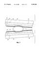
- FIG. 1is a perspective view of a surgical clamp according to the present invention in a position to engage a vessel;
- FIG. 2is a perspective view of the surgical clamp of FIG. 1 engaged with and occluding a vessel;
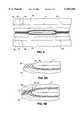
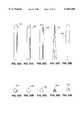
- FIG. 3is a perspective view of a surgical clamp pad capable of attachment to the jaw of a surgical clamp, with a surface containing resilient filaments according to the present invention
- FIG. 4is an enlarged perspective view of the surgical clamp pad of FIG. 3, with parts broken away;
- FIG. 5is an end view of the surgical clamp pad of FIG. 3;
- FIG. 6is a side view of opposed jaws of a surgical clamp with attached clamp pads of FIG. 3 which include opposed surfaces containing resilient filaments, positioned to engage a vessel;
- FIG. 7is a side view according to FIG. 6 where the opposed surfaces containing resilient filaments have engaged the vessel, and the vessel is partially occluded;
- FIG. 8is a side view according to FIG. 7 where the opposed surfaces containing resilient filaments have fully engaged the vessel and the vessel is occluded;
- FIG. 9Ais an enlarged side view of FIG. 8 showing the resilient filaments of the lower opposed surface engaged with the vessel in greater detail;
- FIG. 9Bis an enlarged side view similar to FIG. 9A showing the resilient filaments of the upper opposed surface in a different orientation
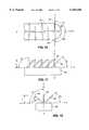
- FIG. 10is a top view of a pad constructed according to the present invention having a different arrangement of resilient filaments, with part of the pad broken away;
- FIG. 11is a side view of the FIG. 10 pad
- FIG. 12is an end view of the FIG. 10 pad
- FIG. 13is top view similar to FIG. 10 of a pad constructed according to the present invention having yet another arrangement of resilient filaments, with part of the pad broken away;
- FIG. 14is a side view of the FIG. 13 pad
- FIG. 15is an end view of the FIG. 13 pad
- FIG. 16is a perspective view of a surgical clamp pad according to the present invention with resilient filaments extending from along the sides of the pad;
- FIG. 17is a side view of the FIG. 16 pad
- FIG. 18Ais a cross-sectional view of the pad shown in FIG. 17 taken along line 18A--18A of FIG. 17;
- FIGS. 18B-18Dare cross-sectional views of pads according to the present invention showing different configurations of resilient filaments
- FIG. 19is a side view of opposed jaws of a surgical clamp with attached clamp pads of FIG. 16 which include opposed surfaces and resilient filaments, and where the surfaces and filaments have engaged the vessel and the vessel is partially occluded;
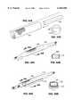
- FIG. 20is a perspective view of a surgical clamp pad with resilient filaments according to the present invention.
- FIG. 21is a side view of the FIG. 20 pad
- FIG. 22is a cross-sectional view of the pad shown in FIG. 21 taken along line 22--22 of FIG. 21;
- FIG. 23is a side view of opposed jaws of a surgical clamp with attached clamp pads of FIG. 20 which include opposed surfaces and resilient filaments, and where the surfaces and filaments have engaged the vessel and the vessel is partially occluded;
- FIG. 24is an exploded perspective view illustrating resilient filaments according to the present invention secured along individual spines
- FIG. 25is a perspective view illustrating the resilient filaments and spines of FIG. 24 in an assembled nested condition
- FIG. 26is a perspective view illustrating the assembled resilient filaments and spines of FIG. 25 embedded in a resilient cushion
- FIG. 27is a top view of a pad constructed according to the present invention having yet another arrangement of resilient filaments, with parts of the pad broken away;
- FIG. 28is a perspective view of the pad shown in FIG. 27;
- FIG. 29is a perspective view of a surgical retractor according to the present invention positioned above a surgical incision site;
- FIG. 30is a side view of a base member of the surgical retractor shown in FIG. 29;
- FIG. 31is a cross-sectional view of the base member shown in FIG. 30, taken on line 31--31 of FIG. 30;
- FIGS. 32A-32Eare side views illustrating different configurations of resilient filaments which may be used in the present invention.
- FIGS. 33A-33Eare end views of the resilient filaments of FIGS. 32A-32E, respectively.
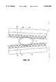
- FIG. 34Ais a perspective view illustrating a tubular sleeve of resilient filaments and a pad prior to assembly according to the present invention
- FIG. 34Bis an end view of the sleeve and pad of FIG. 34A;
- FIG. 35Ais a perspective view of the sleeve and pad of FIG. 34A with the sleeve in a tightened condition against the pad;
- FIG. 35Bis a cross-sectional view of the sleeve and pad shown in FIG. 35A, taken on line 35B--35B of FIG. 35A;
- FIG. 36Ais a perspective view of the sleeve and pad assembly of FIG. 35A, secured to a base member;
- FIG. 36Bis a cross-sectional view of the assembly of FIG. 36A, taken on line 36B--36B of FIG. 36A;
- FIG. 37is a perspective view of the assembly of FIG. 36A showing the removal of excess portions of the sleeve;
- FIG. 38Ais a perspective view of the assembly of FIG. 37 showing the sleeve being cut longitudinally along the pad;
- FIG. 38Bis a perspective view of the assembly of FIG. 38A showing the sleeve completely cut longitudinally along the pad and the resilient filaments of the sleeve extending upward from the pad surface, forming a pad having resilient filaments according to the present invention
- FIG. 38Cis an end view of the pad shown in FIG. 38B;
- FIG. 38Dis an end view of a pad according to the present invention showing a different configuration of resilient filaments
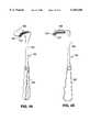
- FIG. 39is a perspective view of another surgical retractor according to the present invention.
- FIG. 40is an enlarged side view of the surgical retractor of FIG. 39 with parts broken away;
- FIG. 41is a perspective view of yet another surgical retractor according to the present invention.
- FIG. 42is an enlarged side view of the surgical retractor of FIG. 41 with parts broken away;
- FIG. 43is a perspective view of a surgical stabilizer according to the present invention.
- FIG. 44is an enlarged side view of the surgical stabilizer of FIG. 43 with parts broken away.
- FIG. 45is a perspective view of the surgical stabilizer of FIG. 43 secured to a rib spreader and positioned within an incision site where the stabilizer has engaged and is stabilizing a heart.
- FIG. 1is a surgical clamp comprising a pair of opposed jaws 22 and 24 and handles 10 and 12 hinged together by pin 14.
- the handles 10 and 12terminate in finger and thumb rings 2 and 4 that provide for manual operation of the jaws by a surgeon.
- Interlocking pawl 6 and ratchet teeth 8are provided on handles 10 and 12, respectively, to secure jaws 22 and 24 in an adjusted clamped position with a vessel V.
- opposed jaws 22 and 24are positioned to engage vessel V.
- the opposed jaws 22 and 24include opposed pads 32, 32 attached to members 30, 30, which are in turn detachably secured to opposed jaws 22 and 24.
- FIG. 2shows the surgical clamp with opposed jaws 22 and 24 in an adjusted clamped position.
- the opposed pads 32, 32clamp vessel V, thereby causing occlusion of vessel V.
- Interlocking ratchet teeth 8are engaged with interlocking pawl 6 to secure the opposed jaws in the clamped position.
- FIGS. 3 and 4An embodiment of the pad 32 and attaching member 30, is depicted in FIGS. 3 and 4.
- the pad 32includes resilient filaments 40 for resisting movement of an occluded vessel relative to the pad 32.
- the resilient filaments 40extend from the pad 32 at acute angles relative to the surface of the pad 32. Any acute angle relative to the surface will operate to resist relative movement of an occluded vessel. The preferred angle is 45 degrees relative to the surface.
- the resilient filaments 40are comprised of a durable yet flexible material, such as nylon or polyester or polypropylene.
- the filamentscannot be so rigid that they puncture the occluded vessel, but they must be of a strength and resiliency such that they resist a force in a direction opposed to the orientation of the filaments.
- the effective length of the filamentswill depend on the length to diameter ratio of the filaments. Filaments that are too short and wide and too rigid may puncture the vessel, whereas filaments too long and narrow may fold over upon themselves when a force is applied and will be unable to restrict relative movement of the vessel.
- the preferred length of the filamentsis 0.030 to 0.075 inches, most preferably 0.060 inches.
- the preferred diameter of the filamentsis 0.005 to 0.012 inches, preferably 0.007 inches. Wider filaments may be used, provided they are sufficiently flexible.
- the ends or tips of the filamentsthemselves can comprise a variety of shapes, as depicted in FIGS. 24 and 25.
- filament 101has a rounded tip
- filament 102has an angled-cut tip
- filament 103has a blunt-cut tip
- filament 104has a pointed tip
- filament 105has a semi-rounded tip.
- the filamentscan be cylindrical 101-103, semi-cylindrical 105, or contain three sides 104 or more.
- the preferred filamentis cylindrical with a rounded tip, as exemplified by filament 101.
- the pad 32is itself comprised of a resilient material, preferably silicone.
- the most preferred composition of the pad 32is two part silicone of less than a 20 durometer, liquid injection moldable (GE 6040) or a silicone foam such as GE RTF762.
- Member 30provides a rigid backing for pad 32 and means for attachment of pad 32 to opposed jaws 22 and 24.
- the member 30can be made of a hard plastic, such as polycarbonate, or of metal.
- a means for attaching pad 32 to an opposed jaw 22 or 24can comprise a pair of protrusions 52 on member 30 detachably coupled to recesses 50 on the jaw.
- FIGS. 6, 7 and 8illustrate the operation of one embodiment of the invention is depicted in FIGS. 6, 7 and 8.
- FIG. 6illustrates upper and lower jaws 22 and 24, opposed members 30, 30, and opposed pads 32, 32 with resilient filaments 40 in a position to engage and occlude vessel V.
- FIG. 7illustrates the above components in partial engagement with vessel V. As depicted in FIG. 7, the resilient members 32, 32 have deflected to accommodate the shape of vessel V, thereby minimizing trauma to vessel V.
- FIG. 8shows the above components in complete engagement with vessel V causing occlusion of vessel V. Some of the resilient filaments have been pressed flat along the resilient members 32, 32 due to the angle at which the vessel V engages those filaments.
- the resilient filaments 40are oriented such that the filaments on the lower pad 32 that abut vessel V will impart a resistive force upward, thereby pushing or levering the vessel V upward into the upper pad 32 in a direction along the general direction of orientation of resilient filaments.
- the resilient filaments on the upper pad 32 that abut the vessel Vwill impart a downward resistive force along the general direction of orientation of those particular resilient filaments.
- the embodiment as shown in FIG. 8will resist movement of the occluded vessel V in one lateral direction relative to the opposed jaws 22 and 24 while permitting lateral movement of the occluded vessel V in the opposite lateral direction relative to the opposed jaws 22 and 24.
- lateral movement of the occluded vessel Vwill be restricted toward the distal ends of the opposed jaws 22 and 24.
- the orientation of the resilient filaments of the upper opposed pad 32can be reversed from that of FIG. 8 such that the resistive force resulting from the filaments on one jaw abutting the vessel restricts lateral movement of the vessel V in one lateral direction relative to opposed pads 32, 32, while the resistive force resulting from the filaments on the other jaw abutting the vessel restricts lateral movement of the vessel V in the opposite lateral direction relative to opposed pads 32, 32.
- the resilient filamentscan be arranged in one or more rows, and oriented in one or more directions.
- FIGS. 10-12depict an embodiment of a particular arrangement of resilient filaments 43-45 extending from the pad 32 arranged in three distinct rows and oriented in three separate directions.
- the surface of pad 32defines a plane (surface plane) containing two axes, an axis X running the length of the pad (longitudinal axis), and an axis Y oriented perpendicular to axis X (perpendicular axis).
- a third axis Zintersects the plane in an orientation normal to the plane (normal axis).
- one row of resilient filamentscomprised of resilient filaments 44, is arranged in a row along longitudinal axis X, and the filaments of this row are oriented at an acute angle C from the surface of the pad 32 in a plane defined by longitudinal axis X and normal axis Z, and at an angle D from the surface in a plane defined by perpendicular axis Y and normal axis Z.
- a second row of resilient filaments, comprised of filaments 43,is arranged along an axis parallel to longitudinal axis X, and the filaments of this row are oriented at an angle A1 from longitudinal axis X in the surface plane, at an angle B from the surface of the pad 32 in a plane defined by longitudinal axis X and normal axis Z, and at an acute angle E1 from the surface in a plane defined by perpendicular axis Y and normal axis Z.
- a third set of resilient filaments, comprised of filaments 45,is likewise arranged along an axis parallel to longitudinal axis X, and the filaments of this row are oriented at an angle A2 from longitudinal axis X in the surface plane, and in a direction generally opposed to the direction of the filaments of the second row with respect to this plane, at an angle B from the surface of the pad 32 in a plane defined by longitudinal axis X and normal axis Z, and at an acute angle E2 from the surface in a plane defined by perpendicular axis Y and normal axis Z.
- This arrangement of resilient filamentswhen engaged with a vessel, will resist movement of the vessel relative to the pad 32 in either direction along perpendicular axis Y, and will also resist movement of the vessel relative to the pad 32 in one of two directions along longitudinal axis X.
- angles A1, A2, B and Dare approximately 90 degrees while the angles C, E1 and E2 are between 30 to 60 degrees, most preferably approximately 45 degrees.
- the number of resilient filaments per rowcan be between 8 and 32, and is preferably 16. Also, it is preferable, though not necessary, that the filaments terminate at the same height L relative to the surface of the pad 32.
- FIGS. 13-15An alternative arrangement of filaments is depicted in FIGS. 13-15.
- resilient filaments extending from pad 32(having a surface plane and longitudinal, perpendicular, and normal axes, X, Y and Z, as described above for FIGS. 10-12) are arranged in two distinct rows and are oriented in two separate directions.
- a first row of resilient filaments, comprised of resilient filaments 46,is arranged along an axis parallel to longitudinal axis X, and the filaments of this row are oriented at an acute angle F1 from longitudinal axis X in the surface plane, at an acute angle G from the surface of pad 32 in a plane defined by longitudinal axis X and normal axis Z, and at an acute angle H1 from the surface in a plane defined by perpendicular axis Y and normal axis Z.
- a second row of resilient filaments, comprised of resilient filaments 47,is likewise arranged along an axis parallel to longitudinal axis X, and the filaments of this row are oriented at an acute angle F2 from longitudinal axis X in the surface plane, at an acute angle G from the surface of the pad 32 in a plane defined by longitudinal axis X and normal axis Z, and at an acute angle H2 from the surface in a plane defined by perpendicular axis Y and normal axis Z.
- the sum of acute angles F1 and F2is less than 180 degrees.
- This arrangement of resilient filamentswhen engaged with a vessel, will resist movement of the vessel relative to the pad 32 in either direction along perpendicular axis Y, and will also resist movement of the vessel relative to the pad 32 in one of two directions along longitudinal axis X.
- angles F1, F2, G, H1 and H2are between 30 to 60 degrees, most preferably approximately 45 degrees.
- the number of resilient filaments per rowcan be between 12 and 48, and is preferably 24. Also, it is preferable, though not necessary, that the filaments terminate at the same height M relative to the pad 32.
- FIG. 16Another embodiment of the pad 32 and attaching member 30 is depicted in FIG. 16.
- resilient filaments 40extend outward from a position where pad 32 attaches to member 30, at an acute angle relative to the surface of pad 32. Any acute angle relative to the surface will operate to resist relative movement of an occluded vessel, the preferred angle being 45 degrees.
- FIGS. 16-18Adepict an embodiment of a particular arrangement of resilient filaments extending from between pad 32 and member 30 in two sets, one on each side of pad 32.
- Each set of filamentsis organized into two intersecting groups.
- the filaments of both groupsextend from between pad 32 and member 30 along a single plane.
- the filaments of each groupare oriented parallel to one another and at an angle relative to the filaments of the other group.
- the preferred angleis a right angle.
- the planes defined by each set of filamentsare oriented at an angle L relative to the surface of pad 32.
- the preferred angle Lis between 45 to 90 degrees, and is most preferably 45 degrees.
- This arrangement of filamentswhen engaged with a vessel, will resist movement of the vessel in either direction relative to the length of the pad. When angle L is less than 90 degrees, the arrangement will also resist movement of an engaged vessel in a direction transverse to the length of the pad.
- the distal ends of the filamentsterminate at a position above the surface of pad 32.
- the filamentsterminate at a position below the surface of pad 32.
- the filamentsterminate at a position slightly above the surface of pad 32. It is also preferable, although not necessary that the filaments terminate at the same height relative to the surface of pad 32.
- the filaments 40are mounted between pad 32 and member 30 and extend outwardly on each side of pad 32.
- member 30has a channel with angled sides that accommodate the filaments 40.
- the pad 32has a bottom surface with a reciprocal shape to fit the channel of member 30.
- member 30has a channel with perpendicular sides. In these embodiments, pad 32 has a flat bottom surface and the filaments 40 are again accommodated between the bottom surface of pad 32 and the channel of member 30.
- FIG. 18Athe filaments 40 are mounted between pad 32 and member 30 and extend outwardly on each side of pad 32.
- member 30has a channel with angled sides that accommodate the filaments 40.
- the pad 32has a bottom surface with a reciprocal shape to fit the channel of member 30.
- member 30has a channel with perpendicular sides. In these embodiments, pad 32 has a flat bottom surface and the filaments 40 are again accommodated between the bottom surface of pad 32 and the channel of member 30.
- FIG. 18Athe filaments 40 are mounted
- the padis divided into upper and lower portions 32a and 32b, and filaments 40 are mounted between the portions and extend outwardly on each side of the pad.
- the lower portion 32bpreferably has a channel with angled sides for receiving the filaments 40 and the upper portion 32a, which has a reciprocally-shaped bottom surface, as depicted in FIG. 18D.
- FIG. 19illustrates upper and lower jaws 22 and 24, and opposed members 30, 30 and opposed pads 32, 32 having resilient members mounted therebetween, in partial engagement with vessel V.
- the filamentshave engaged the vessel V, as have the resilient surfaces of pads 32, 32 which have deflected to accommodate the vessel in atraumatic fashion.
- the abutment of some of the filaments against the vessel Vcreates a resistive force against movement of the vessel.
- the padsengage vessel V first and deflect until the filaments also engage the vessel V.
- FIGS. 20-22An alternative arrangement of filaments is depicted in FIGS. 20-22.
- the filaments 40are arranged in similar fashion to the embodiment depicted in FIG. 16.
- Two sets of filaments 40extend from each side of the pad 32 and each set of filaments is organized into two groups oriented in a single plane with the filaments in each group oriented parallel to one another and at an angle to relative to the filaments of the other group, the preferred angle being a right angle.
- the filaments themselves, however,are mounted, and extend from, the base member 30 itself, as depicted in FIGS. 20-22.
- the distal tips of the filamentsterminate at a position above the surface of pad 32.
- the tipsterminate at a position even with or below the surface of the pad (see, e.g., FIG. 18C).
- FIG. 23The operation of this embodiment of the invention is depicted in FIG. 23 and is essentially identical in operation to that of the embodiment described above and depicted in FIGS. 16-19.
- FIGS. 27 and 28An alternative embodiment to the above embodiments containing two or three rows of resilient filaments is depicted in FIGS. 27 and 28.
- three distinct regions, or strips, of multiple rows of fibers 46extend from pad 32 (having longitudinal and perpendicular axes, X and Y, as described above for FIG. 10-15).
- Each region or stripcontains fibers that are oriented in the same general direction.
- the three distinct regionsare oriented in similar fashion to the three rows of resilient filaments depicted in FIGS. 10-12.
- the fiberscan be comprised of, for example, a synthetic fur.
- the fibersare resilient enough to resist movement of a vessel that abuts against the tips of the fibers.
- This arrangement of fiberswhen engaged with a vessel, will likewise resist movement of the vessel relative to pad 32 in either direction along perpendicular axis Y of pad 32, and will also resist movement of the vessel in one of two directions along longitudinal axis X.
- the preferred method of making this embodiment of the inventionis to glue or otherwise adhere resilient filaments to a suitable backing material, which is then secured to pad 32.
- FIGS. 24-26One method of manufacture is illustrated in FIGS. 24-26. As shown therein, filaments are secured in particular orientations along spines 60, 62 and 64. These spines are arranged in interlocking fashion, as shown in FIG. 25, and then embedded into pad 32, as depicted in FIG. 26. In the preferred method, the arranged spines 60, 62 and 64 are secured in a mold, which is then filled with liquid injection moldable silicone or silicone foam, and the silicone is allowed to cure to form a pad 32 around the filaments.
- the embodiments of the invention described above and depicted in FIGS. 16-23can be manufactured using a plastic weave, such as a nylon mesh or a polyester or polypropylene braid.
- the plastic weaveis comprised of filaments useful in the present invention.
- the filaments of the weaveextend at angles relative to one another.
- a cylindrical sleeve of the weaveis cut in half and one portion is heat treated in a mold to shape the weave into a form that will fit into the channel portion of member 30 as described above and depicted in FIGS. 18A-18C.
- the treated portion of the weaveis then secured in the channel portion of member 30, preferably using an adhesive, together with pad 32.
- the paditself is comprised of resilient material, preferably liquid injection moldable silicone or silicone foam.
- the pad 32is placed within a cylindrical or tubular sleeve of the weave and both are bonded to member 30.
- the weaveis then cut along its axis at or near the surface of pad 32.
- the pad 112is placed within the sleeve 120, as depicted in FIGS. 34A-34B.
- the two ends of the sleeveare then pulled in opposite directions, thereby tightening the sleeve against the pad, as shown in FIGS. 35A-35B.
- the sleeve 120, pad 112, and base member 110are then bonded or otherwise secured together, as depicted in FIGS. 36A-36B.
- An adhesivesuch as cyanoacrylate, for example, LOCTITE 406, can be used to bond sleeve 120, pad 112, and base member 110 together.
- the pad 112can be placed within the sleeve 120, one side of the sleeve can be secured to the pad, and the sleeve can be cut longitudinally along the side generally opposite the secured side prior to securing the sleeve-pad assembly to the base member 110.
- the resultis a pad according to the invention.
- the most preferred material for the pad 112is a 40 durometer urethane or extruded vinyl foam and the most preferred material for the sleeve 120 is a polypropylene braid. In the embodiment depicted in FIG.
- the filaments 122extend outward at an angle P from vertical relative to the surface of the pad 112 and terminate at a height above the surface of the pad.
- the filamentscan also extend upward in a generally vertical direction relative to the surface of the pad 112, as shown in the embodiment depicted in FIG. 38C.
- FIG. 29is a Weitlaner surgical retractor comprising a pair of opposed retracting arms 82 and 84 hinged together by pin 80.
- the distal ends of the retracting arms 86 and 88terminate in retracting fingers 90, 90.
- the proximal ends of the armsterminate in finger and thumb rings 72 and 74 that provide for manual operation of the retracting arms by a surgeon.
- the proximal ends of the armsalso carry an arcuate rack 78 and locking pawl 76 having interlocking ratchet teeth which engage to secure retracting arms 86 and 88 in an open position when retracting tissue at a surgical incision site.
- the gripping elements of the retractorcomprise base members 92 having resilient filaments that extend from the surface of the base members 92 at acute angles. Each base member 92 is securable to retracting fingers 90. As shown in FIG. 30, base member 92 contains apertures 94 which are adapted to receive retracting fingers 90 formed on the arms 86, 88. As shown in FIG. 31, each base member 92 itself has a distal edge 96 and a proximal edge 98.
- resilient filaments of base member 92are comprised of a durable yet flexible material, such as nylon or polyester.
- the filamentscannot be so rigid that they puncture or otherwise traumatize the retracted tissue, but they must be of a strength and resiliency such that they resist a force in a direction opposed to the orientation of the filaments.
- the effective length of the filamentswill depend on the length to diameter ratio of the filaments. Filaments that are too short and wide may puncture or traumatize the retracted tissue, whereas filaments too long and narrow may fold over upon themselves when a force is applied and will be unable to restrict relative movement of the retracted tissue.
- the preferred length of the filamentsis 0.030 to 0.075 inches, most preferably 0.060 inches.
- the preferred diameter of the filamentsis 0.005 to 0.012 inches, preferably 0.007 inches. Wider filaments can be used, provided they are sufficiently flexible.
- the ends or tips of the filamentsthemselves can comprise a variety of shapes, as depicted in FIGS. 32 and 33.
- filament 101has a rounded tip
- filament 102has an angled-cut tip
- filament 103has a blunt-cut tip
- filament 104has a pointed tip
- filament 105has a semi-rounded tip.
- the filamentscan be cylindrical 101-103, semi-cylindrical 105, or contain three sides 104 or more.
- the preferred filamentis cylindrical with a rounded tip, as exemplified by filament 101.
- the surface of base member 92can be of a resilient material, preferably silicone.
- the most preferred composition of the surface of base member 92is two part silicone of less than a 20 durometer, liquid injection moldable (GE 6040) or a silicone foam such as GE RTF762.
- some of the resilient filamentscomprised of resilient filaments 48, are oriented to resist movement of retracted tissue T relative to the base member 92 in the direction of distal edge 96.
- the surface of base member 92defines a plane containing two axes, an axis X running the length of the base member 92 (longitudinal axis) and an axis Y oriented perpendicular to the axis X (perpendicular axis).
- a third axis Zintersects the plane in an orientation normal to the plane (normal axis).
- Resilient filaments 48are oriented at an acute angle K from the surface of base member 92 in a plane formed by perpendicular axis Y and normal axis Z. Additional resilient filaments, comprised of resilient filaments 49, are oriented at acute angles J1 and J2 from the surface of base member 92 in a plane formed by longitudinal axis X and normal axis Z. This arrangement of resilient filaments, when engaged with retracted tissue, will resist movement of the tissue relative to the surface of base member 92 in either direction along longitudinal axis X, and will also resist movement of the tissue relative to the base member 92 along perpendicular axis Y in the direction towards distal edge 96.
- angles J1, J2, and Kare between 30-60 degrees, most preferably approximately 45 degrees, and the number of rows of resilient filaments is 10. It is preferable, though not necessary, that the filaments terminate at the same height N relative to the surface 92.
- FIGS. 39-40show a Richardson surgical retractor 160 comprising a handle 162, arm 164 and retracting blade 168 for retracting tissue at an incision site.
- the retracting blade 168has a resilient pad 170 on the retracting surface and resilient filaments 172 according to the invention that extend from the pad surface at acute angles.
- FIGS. 41-42shows a Balfour surgical retractor 180.
- This retractorhas particular use in retracting tissue at an abdominal incision.
- the retractor 180has lateral blades 181 and 182 fixed to arms 183 and 184 respectively. Arms 183 and 184 are in turn mounted on parallel bars 185 and 186, with arm 183 being movable toward and away from arm 184.
- Center blade 194is fixed to arm 196, which is moveably mounted on bars 185 and 186 for movement of center blade 194 in directions perpendicular to the bars 185 and 186.
- Center blade 194has a resilient pad 190 on the retracting surface and resilient filaments 192 according to the invention that extend from the pad surface at acute angles.
- FIGS. 43-45A surgical stabilizer according to the invention is shown in FIGS. 43-45.
- the stabilizer 200includes bar 202 that is pivotally coupled to member 204.
- Member 204is attached to the base of U-shaped foot member 206.
- Arms 207 and 208extend from the base of foot member 206 for engagement with and stabilization of body tissue or organs.
- Each arm 207 and 208includes a resilient pad 210 having resilient filaments 212 extending therefrom at acute angles relative to the pad surface.
- stabilizing members having resilient filamentscan be provided that are detachably secured to the arms, according to ways described above with respect to surgical clamp pads or retractor base members.
- foot member 206is pressed against the target tissue or organ to stabilize or immobilize the tissue or organ.
- the resilient filaments of arms 207 and 208engage the tissue or organ and the abutment of the engaged filaments against the tissue or organ provides a resistive force that opposes movement of the tissue or organ relative to the arms. This action increases the amount of traction applied by the stabilizer to the stabilized tissue or organ.
- FIG. 45depicts stabilizer 200 in operation to immobilize a patient's beating heart in order to perform bypass surgery.
- Access to the heartis provided by operation of rib spreader 220 that includes base member 226, fixed member 222 and moveable member 223 which is moveable toward and away from fixed member 222 along base member 226.
- Rib spreading arms 224 and 225are secured to members 222 and 223, respectively. The arms 224 and 225 are inserted into an incision and between two adjacent ribs over the heart. Using conventional means not shown, arm 225 and member 223 are moved away from arm 224 and member 222, thereby spreading apart the ribs and providing access to the heart and surrounding tissues.
- Arms 224 and 225are secured in a fixed spaced apart relationship by the tightening of turnscrew 228 down onto a channel formed in base member 226.
- Stabilizer 200is then positioned to impart pressure against the heart to hold it in an immobilized position while it continues beating.
- the stabilizer 200is fixed in pressure-bearing position by means of fastener 214 that secures stabilizer bar 202 against base member 226.
- the secured stabilizerkeeps that portion of the heart between arms 207 and 208 adequately immobilized to allow graft procedures, including anastomosis, to be effectively performed.
- the improved traction provided by the resilient filaments that engage the heartfurther prevent shifting or movement of the heart, yet do so in atraumatic fashion.
Landscapes
- Health & Medical Sciences (AREA)
- Life Sciences & Earth Sciences (AREA)
- Surgery (AREA)
- Molecular Biology (AREA)
- General Health & Medical Sciences (AREA)
- Biomedical Technology (AREA)
- Heart & Thoracic Surgery (AREA)
- Medical Informatics (AREA)
- Nuclear Medicine, Radiotherapy & Molecular Imaging (AREA)
- Animal Behavior & Ethology (AREA)
- Engineering & Computer Science (AREA)
- Public Health (AREA)
- Veterinary Medicine (AREA)
- Reproductive Health (AREA)
- Vascular Medicine (AREA)
- Surgical Instruments (AREA)
- Yarns And Mechanical Finishing Of Yarns Or Ropes (AREA)
- Electron Sources, Ion Sources (AREA)
- Nonwoven Fabrics (AREA)
Abstract
Description
Claims (14)
Priority Applications (4)
| Application Number | Priority Date | Filing Date | Title |
|---|---|---|---|
| US09/337,115US6165186A (en) | 1997-12-18 | 1999-06-21 | Vascular clamps and surgical retractors with directional filaments for tissue engagement |
| US09/521,703US6312445B1 (en) | 1997-12-18 | 2000-03-09 | Vascular clamps and surgical retractors with directional filaments for tissue engagement |
| US09/810,866US6461368B2 (en) | 1997-12-18 | 2001-03-16 | Vascular clamps and surgical retractors with directional filaments for tissue engagement |
| US10/266,431US20030093113A1 (en) | 1997-12-18 | 2002-10-07 | Vascular clamps and surgical retractors with directional filaments for tissue engagement |
Applications Claiming Priority (2)
| Application Number | Priority Date | Filing Date | Title |
|---|---|---|---|
| US08/993,076US6007552A (en) | 1997-12-18 | 1997-12-18 | Vascular clamps and surgical retractors with directional filaments for tissue engagement |
| US09/337,115US6165186A (en) | 1997-12-18 | 1999-06-21 | Vascular clamps and surgical retractors with directional filaments for tissue engagement |
Related Parent Applications (1)
| Application Number | Title | Priority Date | Filing Date |
|---|---|---|---|
| US08/993,076Continuation-In-PartUS6007552A (en) | 1997-12-18 | 1997-12-18 | Vascular clamps and surgical retractors with directional filaments for tissue engagement |
Related Child Applications (1)
| Application Number | Title | Priority Date | Filing Date |
|---|---|---|---|
| US09/521,703ContinuationUS6312445B1 (en) | 1997-12-18 | 2000-03-09 | Vascular clamps and surgical retractors with directional filaments for tissue engagement |
Publications (1)
| Publication Number | Publication Date |
|---|---|
| US6165186Atrue US6165186A (en) | 2000-12-26 |
Family
ID=25539069
Family Applications (5)
| Application Number | Title | Priority Date | Filing Date |
|---|---|---|---|
| US08/993,076Expired - LifetimeUS6007552A (en) | 1997-12-18 | 1997-12-18 | Vascular clamps and surgical retractors with directional filaments for tissue engagement |
| US09/337,115Expired - LifetimeUS6165186A (en) | 1997-12-18 | 1999-06-21 | Vascular clamps and surgical retractors with directional filaments for tissue engagement |
| US09/521,703Expired - LifetimeUS6312445B1 (en) | 1997-12-18 | 2000-03-09 | Vascular clamps and surgical retractors with directional filaments for tissue engagement |
| US09/810,866Expired - LifetimeUS6461368B2 (en) | 1997-12-18 | 2001-03-16 | Vascular clamps and surgical retractors with directional filaments for tissue engagement |
| US10/266,431AbandonedUS20030093113A1 (en) | 1997-12-18 | 2002-10-07 | Vascular clamps and surgical retractors with directional filaments for tissue engagement |
Family Applications Before (1)
| Application Number | Title | Priority Date | Filing Date |
|---|---|---|---|
| US08/993,076Expired - LifetimeUS6007552A (en) | 1997-12-18 | 1997-12-18 | Vascular clamps and surgical retractors with directional filaments for tissue engagement |
Family Applications After (3)
| Application Number | Title | Priority Date | Filing Date |
|---|---|---|---|
| US09/521,703Expired - LifetimeUS6312445B1 (en) | 1997-12-18 | 2000-03-09 | Vascular clamps and surgical retractors with directional filaments for tissue engagement |
| US09/810,866Expired - LifetimeUS6461368B2 (en) | 1997-12-18 | 2001-03-16 | Vascular clamps and surgical retractors with directional filaments for tissue engagement |
| US10/266,431AbandonedUS20030093113A1 (en) | 1997-12-18 | 2002-10-07 | Vascular clamps and surgical retractors with directional filaments for tissue engagement |
Country Status (7)
| Country | Link |
|---|---|
| US (5) | US6007552A (en) |
| EP (1) | EP1039837B1 (en) |
| JP (1) | JP2002508205A (en) |
| AT (1) | ATE266360T1 (en) |
| AU (1) | AU1921099A (en) |
| DE (1) | DE69823871T2 (en) |
| WO (1) | WO1999030623A1 (en) |
Cited By (44)
| Publication number | Priority date | Publication date | Assignee | Title |
|---|---|---|---|---|
| US6716218B2 (en) | 2001-02-28 | 2004-04-06 | Hol-Med Corporation | Instrument for bone distraction and compression having ratcheting tips |
| US20050059988A1 (en)* | 2003-09-16 | 2005-03-17 | Novare Surgical Systems, Inc. | Surgical clamp inserts with hooked traction elements |
| US20060212066A1 (en)* | 2005-03-18 | 2006-09-21 | Castlewood Medical Technologies Llc | System and method for attaching a vein, an artery, or a tube in a vascular environment |
| US20070088402A1 (en)* | 2005-10-18 | 2007-04-19 | Melvin David B | Muscle energy converter with smooth continuous tissue interface |
| US20080269894A1 (en)* | 2005-01-07 | 2008-10-30 | University Of Cincinnati | Prosthetic Anchor and Method of Making Same |
| US20090076454A1 (en)* | 2007-08-21 | 2009-03-19 | Castlewood Surgical, Inc., A Texas Corporation | System and method for providing an obturator for enhanced directional capabilities in a vascular environment |
| US20090307066A1 (en)* | 2007-12-11 | 2009-12-10 | Interactive Marketing, Incorporate | Coupon dispensing methods and systems |
| US7753837B2 (en) | 2003-06-09 | 2010-07-13 | The University Of Cincinnati | Power system for a heart actuation device |
| US8486094B2 (en) | 2007-08-21 | 2013-07-16 | Castlewood Surgical, Inc. | System and method for providing an obturator for enhanced directional capabilities in a vascular environment |
| US8740970B2 (en) | 2009-12-02 | 2014-06-03 | Castlewood Surgical, Inc. | System and method for attaching a vessel in a vascular environment |
| US20140309671A1 (en)* | 2010-04-07 | 2014-10-16 | Miriam Mackovic Basic | Instrument for occlusion of uterine blood vessels |
| US9387066B2 (en) | 2005-01-07 | 2016-07-12 | University Of Cincinnati | Elements for versatility of a prosthetic anchor |
| EP1667585B1 (en)* | 2003-09-16 | 2018-07-04 | Vitalitec International, Inc. | Surgical clamp inserts with hooked traction elements |
| US10420580B2 (en) | 2016-08-25 | 2019-09-24 | Ethicon Llc | Ultrasonic transducer for surgical instrument |
| US10433865B2 (en) | 2007-11-30 | 2019-10-08 | Ethicon Llc | Ultrasonic surgical blades |
| US10441308B2 (en) | 2007-11-30 | 2019-10-15 | Ethicon Llc | Ultrasonic surgical instrument blades |
| US10531910B2 (en) | 2007-07-27 | 2020-01-14 | Ethicon Llc | Surgical instruments |
| US10537352B2 (en)* | 2004-10-08 | 2020-01-21 | Ethicon Llc | Tissue pads for use with surgical instruments |
| US10603064B2 (en) | 2016-11-28 | 2020-03-31 | Ethicon Llc | Ultrasonic transducer |
| US10709906B2 (en) | 2009-05-20 | 2020-07-14 | Ethicon Llc | Coupling arrangements and methods for attaching tools to ultrasonic surgical instruments |
| US10722261B2 (en) | 2007-03-22 | 2020-07-28 | Ethicon Llc | Surgical instruments |
| US10779848B2 (en) | 2006-01-20 | 2020-09-22 | Ethicon Llc | Ultrasound medical instrument having a medical ultrasonic blade |
| US10820920B2 (en) | 2017-07-05 | 2020-11-03 | Ethicon Llc | Reusable ultrasonic medical devices and methods of their use |
| US10828059B2 (en) | 2007-10-05 | 2020-11-10 | Ethicon Llc | Ergonomic surgical instruments |
| US10828057B2 (en) | 2007-03-22 | 2020-11-10 | Ethicon Llc | Ultrasonic surgical instruments |
| US10835768B2 (en) | 2010-02-11 | 2020-11-17 | Ethicon Llc | Dual purpose surgical instrument for cutting and coagulating tissue |
| US10842580B2 (en) | 2012-06-29 | 2020-11-24 | Ethicon Llc | Ultrasonic surgical instruments with control mechanisms |
| US10842522B2 (en) | 2016-07-15 | 2020-11-24 | Ethicon Llc | Ultrasonic surgical instruments having offset blades |
| US10856896B2 (en) | 2005-10-14 | 2020-12-08 | Ethicon Llc | Ultrasonic device for cutting and coagulating |
| US10874418B2 (en) | 2004-02-27 | 2020-12-29 | Ethicon Llc | Ultrasonic surgical shears and method for sealing a blood vessel using same |
| US10893883B2 (en) | 2016-07-13 | 2021-01-19 | Ethicon Llc | Ultrasonic assembly for use with ultrasonic surgical instruments |
| US10952759B2 (en) | 2016-08-25 | 2021-03-23 | Ethicon Llc | Tissue loading of a surgical instrument |
| US10966744B2 (en) | 2016-07-12 | 2021-04-06 | Ethicon Llc | Ultrasonic surgical instrument with piezoelectric central lumen transducer |
| US11020140B2 (en) | 2015-06-17 | 2021-06-01 | Cilag Gmbh International | Ultrasonic surgical blade for use with ultrasonic surgical instruments |
| US11033292B2 (en) | 2013-12-16 | 2021-06-15 | Cilag Gmbh International | Medical device |
| USD924400S1 (en) | 2016-08-16 | 2021-07-06 | Cilag Gmbh International | Surgical instrument |
| US11058447B2 (en) | 2007-07-31 | 2021-07-13 | Cilag Gmbh International | Temperature controlled ultrasonic surgical instruments |
| US11272952B2 (en) | 2013-03-14 | 2022-03-15 | Cilag Gmbh International | Mechanical fasteners for use with surgical energy devices |
| US11369402B2 (en) | 2010-02-11 | 2022-06-28 | Cilag Gmbh International | Control systems for ultrasonically powered surgical instruments |
| US11553954B2 (en) | 2015-06-30 | 2023-01-17 | Cilag Gmbh International | Translatable outer tube for sealing using shielded lap chole dissector |
| US20230078407A1 (en)* | 2020-05-18 | 2023-03-16 | Edwards Lifesciences Corporation | Rib retractor with compliant retractor blade |
| US11666784B2 (en) | 2007-07-31 | 2023-06-06 | Cilag Gmbh International | Surgical instruments |
| US11690641B2 (en) | 2007-07-27 | 2023-07-04 | Cilag Gmbh International | Ultrasonic end effectors with increased active length |
| US11877734B2 (en) | 2007-07-31 | 2024-01-23 | Cilag Gmbh International | Ultrasonic surgical instruments |
Families Citing this family (269)
| Publication number | Priority date | Publication date | Assignee | Title |
|---|---|---|---|---|
| US7435249B2 (en) | 1997-11-12 | 2008-10-14 | Covidien Ag | Electrosurgical instruments which reduces collateral damage to adjacent tissue |
| US6726686B2 (en) | 1997-11-12 | 2004-04-27 | Sherwood Services Ag | Bipolar electrosurgical instrument for sealing vessels |
| US6228083B1 (en) | 1997-11-14 | 2001-05-08 | Sherwood Services Ag | Laparoscopic bipolar electrosurgical instrument |
| US6099539A (en) | 1998-07-27 | 2000-08-08 | Thomas J. Fogarty | Surgical clamp pad with interdigitating teeth |
| US7364577B2 (en) | 2002-02-11 | 2008-04-29 | Sherwood Services Ag | Vessel sealing system |
| US7118570B2 (en) | 2001-04-06 | 2006-10-10 | Sherwood Services Ag | Vessel sealing forceps with disposable electrodes |
| US7267677B2 (en) | 1998-10-23 | 2007-09-11 | Sherwood Services Ag | Vessel sealing instrument |
| US7582087B2 (en) | 1998-10-23 | 2009-09-01 | Covidien Ag | Vessel sealing instrument |
| US6752813B2 (en) | 1999-04-09 | 2004-06-22 | Evalve, Inc. | Methods and devices for capturing and fixing leaflets in valve repair |
| US6315780B1 (en)* | 1999-04-12 | 2001-11-13 | Accurate Surgical & Scientific Instruments Corporation | Bone clamp for dynamic and non-dynamic compression of transverse fractures and method of use thereof |
| US6299621B1 (en) | 1999-06-18 | 2001-10-09 | Novare Surgical Systems, Inc. | Surgical clamp pads with elastomer impregnated mesh |
| US6261308B1 (en)* | 1999-08-09 | 2001-07-17 | Carlos A. Saavedra | Medical forceps for vascular surgery |
| US20030109875A1 (en) | 1999-10-22 | 2003-06-12 | Tetzlaff Philip M. | Open vessel sealing forceps with disposable electrodes |
| CA2391620A1 (en) | 1999-12-03 | 2001-06-21 | Applied Medical Resources Corporation | Vessel occlusion clamp |
| US6719766B1 (en) | 2000-08-24 | 2004-04-13 | Novare Surgical Systems, Inc. | Surgical clamp pads having surface overlay |
| AT408717B (en)* | 2000-09-15 | 2002-02-25 | Dietrich Herbert Dr | Pincers |
| US6610068B1 (en) | 2000-09-22 | 2003-08-26 | Scimed Life Systems, Inc. | Non-flush over-the-wire catheter devices |
| US6673009B1 (en)* | 2000-11-08 | 2004-01-06 | Acorn Cardiovascular, Inc. | Adjustment clamp |
| EP1527747B1 (en) | 2001-04-06 | 2015-09-30 | Covidien AG | Electrosurgical instrument which reduces collateral damage to adjacent tissue |
| ES2262639T3 (en) | 2001-04-06 | 2006-12-01 | Sherwood Services Ag | SHUTTER AND DIVIDER OF GLASSES WITH BUMPER MEMBERS N OCONDUCTIVES. |
| US20080015633A1 (en)* | 2001-09-06 | 2008-01-17 | Ryan Abbott | Systems and Methods for Treating Septal Defects |
| US7513902B2 (en)* | 2001-10-01 | 2009-04-07 | The Cleveland Clinic Foundation | Skin lesion exciser and skin-closure device therefor |
| US6942676B2 (en)* | 2002-03-21 | 2005-09-13 | Novare Surgical Systems, Inc. | Surgical clamp pads with deflecting elements |
| EP1515645B1 (en) | 2002-06-17 | 2006-08-16 | Tyco Healthcare Group Lp | Annular support structures |
| US20040064151A1 (en)* | 2002-09-27 | 2004-04-01 | Starion Instruments Corporation | Ultrasonic forceps |
| US7270664B2 (en) | 2002-10-04 | 2007-09-18 | Sherwood Services Ag | Vessel sealing instrument with electrical cutting mechanism |
| US7276068B2 (en) | 2002-10-04 | 2007-10-02 | Sherwood Services Ag | Vessel sealing instrument with electrical cutting mechanism |
| US7931649B2 (en) | 2002-10-04 | 2011-04-26 | Tyco Healthcare Group Lp | Vessel sealing instrument with electrical cutting mechanism |
| US7799026B2 (en) | 2002-11-14 | 2010-09-21 | Covidien Ag | Compressible jaw configuration with bipolar RF output electrodes for soft tissue fusion |
| EP1572009A2 (en)* | 2002-12-17 | 2005-09-14 | Applied Medical Resources Corporation | Surgical staple-clip and applier |
| US6821284B2 (en)* | 2003-01-22 | 2004-11-23 | Novare Surgical Systems, Inc. | Surgical clamp inserts with micro-tractive surfaces |
| US7651511B2 (en)* | 2003-02-05 | 2010-01-26 | Vascular Control Systems, Inc. | Vascular clamp for caesarian section |
| EP1601298B1 (en) | 2003-03-13 | 2016-09-07 | Covidien AG | Bipolar concentric electrode assembly for soft tissue fusion |
| CA2523675C (en) | 2003-05-01 | 2016-04-26 | Sherwood Services Ag | Electrosurgical instrument which reduces thermal damage to adjacent tissue |
| US7160299B2 (en) | 2003-05-01 | 2007-01-09 | Sherwood Services Ag | Method of fusing biomaterials with radiofrequency energy |
| JP5137230B2 (en) | 2003-05-15 | 2013-02-06 | コヴィディエン・アクチェンゲゼルシャフト | Tissue sealer with non-conductive variable stop member and method for sealing tissue |
| US10631871B2 (en) | 2003-05-19 | 2020-04-28 | Evalve, Inc. | Fixation devices, systems and methods for engaging tissue |
| US7150749B2 (en) | 2003-06-13 | 2006-12-19 | Sherwood Services Ag | Vessel sealer and divider having elongated knife stroke and safety cutting mechanism |
| US7857812B2 (en) | 2003-06-13 | 2010-12-28 | Covidien Ag | Vessel sealer and divider having elongated knife stroke and safety for cutting mechanism |
| USD956973S1 (en) | 2003-06-13 | 2022-07-05 | Covidien Ag | Movable handle for endoscopic vessel sealer and divider |
| US7156846B2 (en) | 2003-06-13 | 2007-01-02 | Sherwood Services Ag | Vessel sealer and divider for use with small trocars and cannulas |
| US6960218B2 (en)* | 2003-10-20 | 2005-11-01 | Henry Rennich | External incontinence clamp |
| US20050241651A1 (en)* | 2003-10-20 | 2005-11-03 | Henry Rennich | External incontinence clamp |
| US7473261B2 (en)* | 2003-10-20 | 2009-01-06 | Henry Rennich | External incontinence clamp |
| US9848938B2 (en) | 2003-11-13 | 2017-12-26 | Covidien Ag | Compressible jaw configuration with bipolar RF output electrodes for soft tissue fusion |
| US7367976B2 (en) | 2003-11-17 | 2008-05-06 | Sherwood Services Ag | Bipolar forceps having monopolar extension |
| US7131970B2 (en) | 2003-11-19 | 2006-11-07 | Sherwood Services Ag | Open vessel sealing instrument with cutting mechanism |
| US7500975B2 (en) | 2003-11-19 | 2009-03-10 | Covidien Ag | Spring loaded reciprocating tissue cutting mechanism in a forceps-style electrosurgical instrument |
| US7811283B2 (en) | 2003-11-19 | 2010-10-12 | Covidien Ag | Open vessel sealing instrument with hourglass cutting mechanism and over-ratchet safety |
| US7442193B2 (en) | 2003-11-20 | 2008-10-28 | Covidien Ag | Electrically conductive/insulative over-shoe for tissue fusion |
| US20050125033A1 (en)* | 2003-12-04 | 2005-06-09 | Mcnally-Heintzelman Karen M. | Wound closure apparatus |
| US7780662B2 (en) | 2004-03-02 | 2010-08-24 | Covidien Ag | Vessel sealing system using capacitive RF dielectric heating |
| US20050240219A1 (en)* | 2004-04-22 | 2005-10-27 | Henry Kahle | Peripheral vascular occlusion devices |
| US7195631B2 (en) | 2004-09-09 | 2007-03-27 | Sherwood Services Ag | Forceps with spring loaded end effector assembly |
| US7540872B2 (en) | 2004-09-21 | 2009-06-02 | Covidien Ag | Articulating bipolar electrosurgical instrument |
| US7955332B2 (en) | 2004-10-08 | 2011-06-07 | Covidien Ag | Mechanism for dividing tissue in a hemostat-style instrument |
| US8372094B2 (en) | 2004-10-15 | 2013-02-12 | Covidien Lp | Seal element for anastomosis |
| US7823592B2 (en) | 2004-10-18 | 2010-11-02 | Tyco Healthcare Group Lp | Annular adhesive structure |
| US7845536B2 (en) | 2004-10-18 | 2010-12-07 | Tyco Healthcare Group Lp | Annular adhesive structure |
| US7938307B2 (en) | 2004-10-18 | 2011-05-10 | Tyco Healthcare Group Lp | Support structures and methods of using the same |
| US20060135966A1 (en)* | 2004-11-15 | 2006-06-22 | Laurent Schaller | Catheter-based tissue remodeling devices and methods |
| US7686804B2 (en) | 2005-01-14 | 2010-03-30 | Covidien Ag | Vessel sealer and divider with rotating sealer and cutter |
| US7909823B2 (en) | 2005-01-14 | 2011-03-22 | Covidien Ag | Open vessel sealing instrument |
| US7942890B2 (en) | 2005-03-15 | 2011-05-17 | Tyco Healthcare Group Lp | Anastomosis composite gasket |
| US9364229B2 (en) | 2005-03-15 | 2016-06-14 | Covidien Lp | Circular anastomosis structures |
| US7491202B2 (en) | 2005-03-31 | 2009-02-17 | Covidien Ag | Electrosurgical forceps with slow closure sealing plates and method of sealing tissue |
| US10735576B1 (en)* | 2005-07-14 | 2020-08-04 | Binj Laboratories, Inc. | Systems and methods for detecting and controlling transmission devices |
| US9197993B2 (en) | 2005-07-14 | 2015-11-24 | Binj Laboratories, Inc | System and method for detecting and controlling transmission devices |
| US9226259B2 (en) | 2005-07-14 | 2015-12-29 | Binj Laboratories, Inc. | Systems and methods for detecting and controlling transmission devices |
| US7789878B2 (en) | 2005-09-30 | 2010-09-07 | Covidien Ag | In-line vessel sealer and divider |
| CA2561034C (en) | 2005-09-30 | 2014-12-09 | Sherwood Services Ag | Flexible endoscopic catheter with an end effector for coagulating and transfecting tissue |
| US7722607B2 (en) | 2005-09-30 | 2010-05-25 | Covidien Ag | In-line vessel sealer and divider |
| US7879035B2 (en) | 2005-09-30 | 2011-02-01 | Covidien Ag | Insulating boot for electrosurgical forceps |
| ES2381560T3 (en) | 2005-09-30 | 2012-05-29 | Covidien Ag | Insulating sleeve for electrosurgical forceps |
| US7922953B2 (en) | 2005-09-30 | 2011-04-12 | Covidien Ag | Method for manufacturing an end effector assembly |
| US8241282B2 (en) | 2006-01-24 | 2012-08-14 | Tyco Healthcare Group Lp | Vessel sealing cutting assemblies |
| US8734443B2 (en) | 2006-01-24 | 2014-05-27 | Covidien Lp | Vessel sealer and divider for large tissue structures |
| US8298232B2 (en) | 2006-01-24 | 2012-10-30 | Tyco Healthcare Group Lp | Endoscopic vessel sealer and divider for large tissue structures |
| US8882766B2 (en) | 2006-01-24 | 2014-11-11 | Covidien Ag | Method and system for controlling delivery of energy to divide tissue |
| US9629626B2 (en) | 2006-02-02 | 2017-04-25 | Covidien Lp | Mechanically tuned buttress material to assist with proper formation of surgical element in diseased tissue |
| US7793813B2 (en) | 2006-02-28 | 2010-09-14 | Tyco Healthcare Group Lp | Hub for positioning annular structure on a surgical device |
| EP2015681B1 (en) | 2006-05-03 | 2018-03-28 | Datascope Corp. | Tissue closure device |
| WO2008005385A2 (en) | 2006-06-30 | 2008-01-10 | Cvdevices, Llc | Atraumatic clamp |
| US7776037B2 (en) | 2006-07-07 | 2010-08-17 | Covidien Ag | System and method for controlling electrode gap during tissue sealing |
| US8597297B2 (en) | 2006-08-29 | 2013-12-03 | Covidien Ag | Vessel sealing instrument with multiple electrode configurations |
| US8070746B2 (en) | 2006-10-03 | 2011-12-06 | Tyco Healthcare Group Lp | Radiofrequency fusion of cardiac tissue |
| US8028883B2 (en) | 2006-10-26 | 2011-10-04 | Tyco Healthcare Group Lp | Methods of using shape memory alloys for buttress attachment |
| US7845533B2 (en) | 2007-06-22 | 2010-12-07 | Tyco Healthcare Group Lp | Detachable buttress material retention systems for use with a surgical stapling device |
| USD649249S1 (en) | 2007-02-15 | 2011-11-22 | Tyco Healthcare Group Lp | End effectors of an elongated dissecting and dividing instrument |
| EP3087929B1 (en) | 2007-03-06 | 2020-04-29 | Covidien LP | Surgical stapling apparatus |
| US8011555B2 (en) | 2007-03-06 | 2011-09-06 | Tyco Healthcare Group Lp | Surgical stapling apparatus |
| US8011550B2 (en) | 2009-03-31 | 2011-09-06 | Tyco Healthcare Group Lp | Surgical stapling apparatus |
| US8267935B2 (en) | 2007-04-04 | 2012-09-18 | Tyco Healthcare Group Lp | Electrosurgical instrument reducing current densities at an insulator conductor junction |
| US8038045B2 (en) | 2007-05-25 | 2011-10-18 | Tyco Healthcare Group Lp | Staple buttress retention system |
| US7950561B2 (en) | 2007-06-18 | 2011-05-31 | Tyco Healthcare Group Lp | Structure for attachment of buttress material to anvils and cartridges of surgical staplers |
| US7665646B2 (en) | 2007-06-18 | 2010-02-23 | Tyco Healthcare Group Lp | Interlocking buttress material retention system |
| US8062330B2 (en) | 2007-06-27 | 2011-11-22 | Tyco Healthcare Group Lp | Buttress and surgical stapling apparatus |
| US20090062869A1 (en)* | 2007-08-28 | 2009-03-05 | Perception Raisonnement Action En Medecine | Minimally invasive bone fixation clamp for navigated surgeries |
| US7877853B2 (en) | 2007-09-20 | 2011-02-01 | Tyco Healthcare Group Lp | Method of manufacturing end effector assembly for sealing tissue |
| US7877852B2 (en) | 2007-09-20 | 2011-02-01 | Tyco Healthcare Group Lp | Method of manufacturing an end effector assembly for sealing tissue |
| US9023043B2 (en) | 2007-09-28 | 2015-05-05 | Covidien Lp | Insulating mechanically-interfaced boot and jaws for electrosurgical forceps |
| US8221416B2 (en) | 2007-09-28 | 2012-07-17 | Tyco Healthcare Group Lp | Insulating boot for electrosurgical forceps with thermoplastic clevis |
| US8235993B2 (en) | 2007-09-28 | 2012-08-07 | Tyco Healthcare Group Lp | Insulating boot for electrosurgical forceps with exohinged structure |
| US8267936B2 (en) | 2007-09-28 | 2012-09-18 | Tyco Healthcare Group Lp | Insulating mechanically-interfaced adhesive for electrosurgical forceps |
| US8235992B2 (en) | 2007-09-28 | 2012-08-07 | Tyco Healthcare Group Lp | Insulating boot with mechanical reinforcement for electrosurgical forceps |
| US8236025B2 (en) | 2007-09-28 | 2012-08-07 | Tyco Healthcare Group Lp | Silicone insulated electrosurgical forceps |
| AU2008221509B2 (en) | 2007-09-28 | 2013-10-10 | Covidien Lp | Dual durometer insulating boot for electrosurgical forceps |
| US8251996B2 (en) | 2007-09-28 | 2012-08-28 | Tyco Healthcare Group Lp | Insulating sheath for electrosurgical forceps |
| US20090105720A1 (en)* | 2007-10-19 | 2009-04-23 | Boone Brenda J | Non-invasive surgical tenaculum |
| US8764748B2 (en) | 2008-02-06 | 2014-07-01 | Covidien Lp | End effector assembly for electrosurgical device and method for making the same |
| US8623276B2 (en) | 2008-02-15 | 2014-01-07 | Covidien Lp | Method and system for sterilizing an electrosurgical instrument |
| US8066635B2 (en)* | 2008-03-05 | 2011-11-29 | Thb Precision, Llc | Speculum |
| US20090264897A1 (en)* | 2008-03-18 | 2009-10-22 | Wohl Daniel L | Tonsil forceps |
| AU2009234286B2 (en)* | 2008-04-11 | 2015-02-12 | Physcient, Inc. | Methods and devices to decrease tissue trauma during surgery |
| JP5443474B2 (en)* | 2008-05-07 | 2014-03-19 | ジンテス ゲゼルシャフト ミット ベシュレンクテル ハフツング | Method and apparatus for lateral access to intervertebral disc space |
| US8915845B2 (en)* | 2008-05-14 | 2014-12-23 | Physcient, Inc. | Methods and devices to decrease tissue trauma during surgery |
| US8469956B2 (en) | 2008-07-21 | 2013-06-25 | Covidien Lp | Variable resistor jaw |
| US8257387B2 (en) | 2008-08-15 | 2012-09-04 | Tyco Healthcare Group Lp | Method of transferring pressure in an articulating surgical instrument |
| US8162973B2 (en)* | 2008-08-15 | 2012-04-24 | Tyco Healthcare Group Lp | Method of transferring pressure in an articulating surgical instrument |
| US9603652B2 (en) | 2008-08-21 | 2017-03-28 | Covidien Lp | Electrosurgical instrument including a sensor |
| US8317787B2 (en) | 2008-08-28 | 2012-11-27 | Covidien Lp | Tissue fusion jaw angle improvement |
| US8784417B2 (en) | 2008-08-28 | 2014-07-22 | Covidien Lp | Tissue fusion jaw angle improvement |
| US8795274B2 (en) | 2008-08-28 | 2014-08-05 | Covidien Lp | Tissue fusion jaw angle improvement |
| US8303582B2 (en) | 2008-09-15 | 2012-11-06 | Tyco Healthcare Group Lp | Electrosurgical instrument having a coated electrode utilizing an atomic layer deposition technique |
| US8535312B2 (en) | 2008-09-25 | 2013-09-17 | Covidien Lp | Apparatus, system and method for performing an electrosurgical procedure |
| US9375254B2 (en) | 2008-09-25 | 2016-06-28 | Covidien Lp | Seal and separate algorithm |
| US8968314B2 (en) | 2008-09-25 | 2015-03-03 | Covidien Lp | Apparatus, system and method for performing an electrosurgical procedure |
| JP5388095B2 (en)* | 2008-09-30 | 2014-01-15 | 公益財団法人北九州産業学術推進機構 | Pinching device |
| US8142473B2 (en) | 2008-10-03 | 2012-03-27 | Tyco Healthcare Group Lp | Method of transferring rotational motion in an articulating surgical instrument |
| US8469957B2 (en) | 2008-10-07 | 2013-06-25 | Covidien Lp | Apparatus, system, and method for performing an electrosurgical procedure |
| US8016827B2 (en) | 2008-10-09 | 2011-09-13 | Tyco Healthcare Group Lp | Apparatus, system, and method for performing an electrosurgical procedure |
| US8636761B2 (en) | 2008-10-09 | 2014-01-28 | Covidien Lp | Apparatus, system, and method for performing an endoscopic electrosurgical procedure |
| US8486107B2 (en) | 2008-10-20 | 2013-07-16 | Covidien Lp | Method of sealing tissue using radiofrequency energy |
| US8197479B2 (en) | 2008-12-10 | 2012-06-12 | Tyco Healthcare Group Lp | Vessel sealer and divider |
| US20100147921A1 (en) | 2008-12-16 | 2010-06-17 | Lee Olson | Surgical Apparatus Including Surgical Buttress |
| US8114122B2 (en) | 2009-01-13 | 2012-02-14 | Tyco Healthcare Group Lp | Apparatus, system, and method for performing an electrosurgical procedure |
| US7967179B2 (en) | 2009-03-31 | 2011-06-28 | Tyco Healthcare Group Lp | Center cinch and release of buttress material |
| US9486215B2 (en) | 2009-03-31 | 2016-11-08 | Covidien Lp | Surgical stapling apparatus |
| US8348126B2 (en) | 2009-03-31 | 2013-01-08 | Covidien Lp | Crimp and release of suture holding buttress material |
| US7988027B2 (en) | 2009-03-31 | 2011-08-02 | Tyco Healthcare Group Lp | Crimp and release of suture holding buttress material |
| US8365972B2 (en) | 2009-03-31 | 2013-02-05 | Covidien Lp | Surgical stapling apparatus |
| US8016178B2 (en) | 2009-03-31 | 2011-09-13 | Tyco Healthcare Group Lp | Surgical stapling apparatus |
| US9402610B2 (en) | 2009-04-13 | 2016-08-02 | Physcient, Inc. | Rib-protecting devices for thoracoscopic surgery, and related methods |
| US8187273B2 (en) | 2009-05-07 | 2012-05-29 | Tyco Healthcare Group Lp | Apparatus, system, and method for performing an electrosurgical procedure |
| US8246618B2 (en) | 2009-07-08 | 2012-08-21 | Tyco Healthcare Group Lp | Electrosurgical jaws with offset knife |
| US8133254B2 (en) | 2009-09-18 | 2012-03-13 | Tyco Healthcare Group Lp | In vivo attachable and detachable end effector assembly and laparoscopic surgical instrument and methods therefor |
| US8112871B2 (en) | 2009-09-28 | 2012-02-14 | Tyco Healthcare Group Lp | Method for manufacturing electrosurgical seal plates |
| US8157151B2 (en) | 2009-10-15 | 2012-04-17 | Tyco Healthcare Group Lp | Staple line reinforcement for anvil and cartridge |
| US9693772B2 (en) | 2009-10-15 | 2017-07-04 | Covidien Lp | Staple line reinforcement for anvil and cartridge |
| US9610080B2 (en) | 2009-10-15 | 2017-04-04 | Covidien Lp | Staple line reinforcement for anvil and cartridge |
| US10842485B2 (en) | 2009-10-15 | 2020-11-24 | Covidien Lp | Brachytherapy buttress |
| US10293553B2 (en) | 2009-10-15 | 2019-05-21 | Covidien Lp | Buttress brachytherapy and integrated staple line markers for margin identification |
| US20150231409A1 (en) | 2009-10-15 | 2015-08-20 | Covidien Lp | Buttress brachytherapy and integrated staple line markers for margin identification |
| USD622381S1 (en)* | 2009-11-10 | 2010-08-24 | Hamid Cyrus Hajarian | Surgical retractor with suction tip |
| US10010336B2 (en)* | 2009-12-22 | 2018-07-03 | Cook Medical Technologies, Inc. | Medical devices with detachable pivotable jaws |
| CN102762157B (en) | 2009-12-22 | 2015-04-01 | 库克医学技术有限责任公司 | Medical device with detachable pivotable caliper |
| TWM378932U (en)* | 2009-12-25 | 2010-04-21 | Food Industry Res & Dev Inst | Cutting device for culturing the next generation of cells |
| WO2011146739A1 (en) | 2010-05-19 | 2011-11-24 | Physcient, Inc. | Methods and devices to decrease tissue trauma during surgery |
| EP2627264B1 (en) | 2010-10-11 | 2015-06-17 | Cook Medical Technologies LLC | Medical devices with detachable pivotable jaws |
| BR112013008763B1 (en) | 2010-10-11 | 2021-02-17 | Cook Medical Technologies LLC. | medical device for engaging a tissue |
| US9017349B2 (en) | 2010-10-27 | 2015-04-28 | Atricure, Inc. | Appendage clamp deployment assist device |
| US20120150213A1 (en)* | 2010-12-10 | 2012-06-14 | Charles Samuel Squire Gordon | Medical compression device |
| US8348130B2 (en) | 2010-12-10 | 2013-01-08 | Covidien Lp | Surgical apparatus including surgical buttress |
| US9113940B2 (en) | 2011-01-14 | 2015-08-25 | Covidien Lp | Trigger lockout and kickback mechanism for surgical instruments |
| US9084602B2 (en) | 2011-01-26 | 2015-07-21 | Covidien Lp | Buttress film with hemostatic action for surgical stapling apparatus |
| US8479968B2 (en) | 2011-03-10 | 2013-07-09 | Covidien Lp | Surgical instrument buttress attachment |
| US8568408B2 (en)* | 2011-04-21 | 2013-10-29 | Covidien Lp | Surgical forceps |
| US8789737B2 (en) | 2011-04-27 | 2014-07-29 | Covidien Lp | Circular stapler and staple line reinforcement material |
| US8945177B2 (en) | 2011-09-13 | 2015-02-03 | Abbott Cardiovascular Systems Inc. | Gripper pusher mechanism for tissue apposition systems |
| US9675351B2 (en) | 2011-10-26 | 2017-06-13 | Covidien Lp | Buttress release from surgical stapler by knife pushing |
| US8584920B2 (en) | 2011-11-04 | 2013-11-19 | Covidien Lp | Surgical stapling apparatus including releasable buttress |
| US9113885B2 (en) | 2011-12-14 | 2015-08-25 | Covidien Lp | Buttress assembly for use with surgical stapling device |
| US9351732B2 (en) | 2011-12-14 | 2016-05-31 | Covidien Lp | Buttress attachment to degradable polymer zones |
| US8967448B2 (en) | 2011-12-14 | 2015-03-03 | Covidien Lp | Surgical stapling apparatus including buttress attachment via tabs |
| US9237892B2 (en) | 2011-12-14 | 2016-01-19 | Covidien Lp | Buttress attachment to the cartridge surface |
| US9010608B2 (en) | 2011-12-14 | 2015-04-21 | Covidien Lp | Releasable buttress retention on a surgical stapler |
| US9351731B2 (en) | 2011-12-14 | 2016-05-31 | Covidien Lp | Surgical stapling apparatus including releasable surgical buttress |
| USD680220S1 (en) | 2012-01-12 | 2013-04-16 | Coviden IP | Slider handle for laparoscopic device |
| US9326773B2 (en) | 2012-01-26 | 2016-05-03 | Covidien Lp | Surgical device including buttress material |
| US9010612B2 (en) | 2012-01-26 | 2015-04-21 | Covidien Lp | Buttress support design for EEA anvil |
| US9010609B2 (en) | 2012-01-26 | 2015-04-21 | Covidien Lp | Circular stapler including buttress |
| US9931116B2 (en) | 2012-02-10 | 2018-04-03 | Covidien Lp | Buttress composition |
| US8820606B2 (en) | 2012-02-24 | 2014-09-02 | Covidien Lp | Buttress retention system for linear endostaplers |
| US8679140B2 (en) | 2012-05-30 | 2014-03-25 | Covidien Lp | Surgical clamping device with ratcheting grip lock |
| US9572576B2 (en) | 2012-07-18 | 2017-02-21 | Covidien Lp | Surgical apparatus including surgical buttress |
| US20140048580A1 (en) | 2012-08-20 | 2014-02-20 | Covidien Lp | Buttress attachment features for surgical stapling apparatus |
| US9161753B2 (en) | 2012-10-10 | 2015-10-20 | Covidien Lp | Buttress fixation for a circular stapler |
| USD704835S1 (en)* | 2012-10-22 | 2014-05-13 | Hamid Cyrus Hajarian | Surgical retractor with suction tip |
| US20140131418A1 (en) | 2012-11-09 | 2014-05-15 | Covidien Lp | Surgical Stapling Apparatus Including Buttress Attachment |
| US9192384B2 (en) | 2012-11-09 | 2015-11-24 | Covidien Lp | Recessed groove for better suture retention |
| US9901351B2 (en) | 2012-11-21 | 2018-02-27 | Atricure, Inc. | Occlusion clip |
| US9295466B2 (en) | 2012-11-30 | 2016-03-29 | Covidien Lp | Surgical apparatus including surgical buttress |
| US9681936B2 (en) | 2012-11-30 | 2017-06-20 | Covidien Lp | Multi-layer porous film material |
| US9402627B2 (en) | 2012-12-13 | 2016-08-02 | Covidien Lp | Folded buttress for use with a surgical apparatus |
| US9522002B2 (en) | 2012-12-13 | 2016-12-20 | Covidien Lp | Surgical instrument with pressure distribution device |
| US9204881B2 (en) | 2013-01-11 | 2015-12-08 | Covidien Lp | Buttress retainer for EEA anvil |
| US9433420B2 (en) | 2013-01-23 | 2016-09-06 | Covidien Lp | Surgical apparatus including surgical buttress |
| US9192383B2 (en) | 2013-02-04 | 2015-11-24 | Covidien Lp | Circular stapling device including buttress material |
| US9414839B2 (en) | 2013-02-04 | 2016-08-16 | Covidien Lp | Buttress attachment for circular stapling device |
| US9504470B2 (en) | 2013-02-25 | 2016-11-29 | Covidien Lp | Circular stapling device with buttress |
| US20140239047A1 (en) | 2013-02-28 | 2014-08-28 | Covidien Lp | Adherence concepts for non-woven absorbable felt buttresses |
| US9782173B2 (en) | 2013-03-07 | 2017-10-10 | Covidien Lp | Circular stapling device including buttress release mechanism |
| CN103382082B (en)* | 2013-07-11 | 2015-07-22 | 深圳市华星光电技术有限公司 | Gasket structure and fragmentation device using the same |
| CN105451670B (en) | 2013-08-07 | 2018-09-04 | 柯惠有限合伙公司 | Surgery forceps |
| US9655620B2 (en) | 2013-10-28 | 2017-05-23 | Covidien Lp | Circular surgical stapling device including buttress material |
| WO2015077356A1 (en) | 2013-11-19 | 2015-05-28 | Wheeler William K | Fastener applicator with interlock |
| BR112016011572B1 (en)* | 2013-11-21 | 2022-08-16 | Atricure, Inc | OCCLUSION CLAMP |
| US9999414B2 (en) | 2014-01-24 | 2018-06-19 | Contour Surgical, Inc. | Retraction devices and methods of its use and manufacture |
| CN106535801B (en)* | 2014-04-02 | 2020-09-04 | 美国奥林匹斯外科技术吉鲁斯阿克米公司 | Surgical device with replaceable elements |
| US9844378B2 (en) | 2014-04-29 | 2017-12-19 | Covidien Lp | Surgical stapling apparatus and methods of adhering a surgical buttress thereto |
| US10231777B2 (en) | 2014-08-26 | 2019-03-19 | Covidien Lp | Methods of manufacturing jaw members of an end-effector assembly for a surgical instrument |
| US10835216B2 (en) | 2014-12-24 | 2020-11-17 | Covidien Lp | Spinneret for manufacture of melt blown nonwoven fabric |
| US10470767B2 (en) | 2015-02-10 | 2019-11-12 | Covidien Lp | Surgical stapling instrument having ultrasonic energy delivery |
| US10524912B2 (en) | 2015-04-02 | 2020-01-07 | Abbott Cardiovascular Systems, Inc. | Tissue fixation devices and methods |
| US11020578B2 (en) | 2015-04-10 | 2021-06-01 | Covidien Lp | Surgical stapler with integrated bladder |
| US10667815B2 (en) | 2015-07-21 | 2020-06-02 | Evalve, Inc. | Tissue grasping devices and related methods |
| US10987159B2 (en) | 2015-08-26 | 2021-04-27 | Covidien Lp | Electrosurgical end effector assemblies and electrosurgical forceps configured to reduce thermal spread |
| US10213250B2 (en) | 2015-11-05 | 2019-02-26 | Covidien Lp | Deployment and safety mechanisms for surgical instruments |
| US10959731B2 (en) | 2016-06-14 | 2021-03-30 | Covidien Lp | Buttress attachment for surgical stapling instrument |
| US11026686B2 (en) | 2016-11-08 | 2021-06-08 | Covidien Lp | Structure for attaching buttress to anvil and/or cartridge of surgical stapling instrument |
| US11602364B2 (en) | 2016-11-16 | 2023-03-14 | Cilag Gmbh International | Surgical instrument with removable end effector components |
| US10779837B2 (en) | 2016-12-08 | 2020-09-22 | Evalve, Inc. | Adjustable arm device for grasping tissues |
| US10874768B2 (en) | 2017-01-20 | 2020-12-29 | Covidien Lp | Drug eluting medical device |
| US10925607B2 (en) | 2017-02-28 | 2021-02-23 | Covidien Lp | Surgical stapling apparatus with staple sheath |
| US10368868B2 (en) | 2017-03-09 | 2019-08-06 | Covidien Lp | Structure for attaching buttress material to anvil and cartridge of surgical stapling instrument |
| US11096610B2 (en) | 2017-03-28 | 2021-08-24 | Covidien Lp | Surgical implants including sensing fibers |
| US11166759B2 (en) | 2017-05-16 | 2021-11-09 | Covidien Lp | Surgical forceps |
| CA3068282C (en) | 2017-06-22 | 2022-06-28 | Teleflex Medical Incorporated | Surgical clip |
| US10849625B2 (en) | 2017-08-07 | 2020-12-01 | Covidien Lp | Surgical buttress retention systems for surgical stapling apparatus |
| US10945733B2 (en) | 2017-08-23 | 2021-03-16 | Covidien Lp | Surgical buttress reload and tip attachment assemblies for surgical stapling apparatus |
| ES2981210T3 (en) | 2017-11-14 | 2024-10-07 | Teleflex Medical Inc | Surgical clip |
| US11141151B2 (en) | 2017-12-08 | 2021-10-12 | Covidien Lp | Surgical buttress for circular stapling |
| US11266449B2 (en) | 2017-12-19 | 2022-03-08 | Orthopediatrics Corp | Osteotomy device and methods |
| US11065000B2 (en) | 2018-02-22 | 2021-07-20 | Covidien Lp | Surgical buttresses for surgical stapling apparatus |
| JP7348199B2 (en) | 2018-03-28 | 2023-09-20 | データスコープ コーポレイション | Device for atrial appendage exclusion |
| US10758237B2 (en) | 2018-04-30 | 2020-09-01 | Covidien Lp | Circular stapling apparatus with pinned buttress |
| US11426163B2 (en) | 2018-05-09 | 2022-08-30 | Covidien Lp | Universal linear surgical stapling buttress |
| US11432818B2 (en) | 2018-05-09 | 2022-09-06 | Covidien Lp | Surgical buttress assemblies |
| US11284896B2 (en) | 2018-05-09 | 2022-03-29 | Covidien Lp | Surgical buttress loading and attaching/detaching assemblies |
| US11219460B2 (en) | 2018-07-02 | 2022-01-11 | Covidien Lp | Surgical stapling apparatus with anvil buttress |
| US10806459B2 (en) | 2018-09-14 | 2020-10-20 | Covidien Lp | Drug patterned reinforcement material for circular anastomosis |
| US11253697B2 (en)* | 2018-09-23 | 2022-02-22 | Ning Miao Su | Implantable cuff with an integral closure mechanism |
| US10952729B2 (en) | 2018-10-03 | 2021-03-23 | Covidien Lp | Universal linear buttress retention/release assemblies and methods |
| US11730472B2 (en) | 2019-04-25 | 2023-08-22 | Covidien Lp | Surgical system and surgical loading units thereof |
| US11478245B2 (en) | 2019-05-08 | 2022-10-25 | Covidien Lp | Surgical stapling device |
| US11596403B2 (en) | 2019-05-08 | 2023-03-07 | Covidien Lp | Surgical stapling device |
| US11660095B2 (en) | 2019-05-23 | 2023-05-30 | Lipocosm, Llc | Devices and methods for wound closure |
| US11464515B2 (en)* | 2019-05-23 | 2022-10-11 | Liopcosm, LLC | Devices and methods for wound closure |
| JP7543391B2 (en) | 2019-07-15 | 2024-09-02 | エバルブ,インコーポレイティド | Method of Actuating Individual Proximal Elements |
| US11969169B2 (en) | 2019-09-10 | 2024-04-30 | Covidien Lp | Anvil buttress loading unit for a surgical stapling apparatus |
| US11571208B2 (en) | 2019-10-11 | 2023-02-07 | Covidien Lp | Surgical buttress loading units |
| US11523824B2 (en) | 2019-12-12 | 2022-12-13 | Covidien Lp | Anvil buttress loading for a surgical stapling apparatus |
| EP4076216A1 (en) | 2019-12-19 | 2022-10-26 | Teleflex Medical Incorporated | Surgical clip |
| US11547407B2 (en) | 2020-03-19 | 2023-01-10 | Covidien Lp | Staple line reinforcement for surgical stapling apparatus |
| US11337699B2 (en) | 2020-04-28 | 2022-05-24 | Covidien Lp | Magnesium infused surgical buttress for surgical stapler |
| US11707276B2 (en) | 2020-09-08 | 2023-07-25 | Covidien Lp | Surgical buttress assemblies and techniques for surgical stapling |
| US11399833B2 (en) | 2020-10-19 | 2022-08-02 | Covidien Lp | Anvil buttress attachment for surgical stapling apparatus |
| US11534170B2 (en) | 2021-01-04 | 2022-12-27 | Covidien Lp | Anvil buttress attachment for surgical stapling apparatus |
| US11510670B1 (en) | 2021-06-23 | 2022-11-29 | Covidien Lp | Buttress attachment for surgical stapling apparatus |
| US11596399B2 (en) | 2021-06-23 | 2023-03-07 | Covidien Lp | Anvil buttress attachment for surgical stapling apparatus |
| US11672538B2 (en) | 2021-06-24 | 2023-06-13 | Covidien Lp | Surgical stapling device including a buttress retention assembly |
| US11678879B2 (en) | 2021-07-01 | 2023-06-20 | Covidien Lp | Buttress attachment for surgical stapling apparatus |
| US11684368B2 (en) | 2021-07-14 | 2023-06-27 | Covidien Lp | Surgical stapling device including a buttress retention assembly |
| US12076013B2 (en) | 2021-08-03 | 2024-09-03 | Covidien Lp | Surgical buttress attachment assemblies for surgical stapling apparatus |
| US11801052B2 (en) | 2021-08-30 | 2023-10-31 | Covidien Lp | Assemblies for surgical stapling instruments |
| US11751875B2 (en) | 2021-10-13 | 2023-09-12 | Coviden Lp | Surgical buttress attachment assemblies for surgical stapling apparatus |
| US11806017B2 (en) | 2021-11-23 | 2023-11-07 | Covidien Lp | Anvil buttress loading system for surgical stapling apparatus |
| EP4482400A1 (en) | 2022-02-24 | 2025-01-01 | Covidien LP | Surgical medical devices |
| US20240122604A1 (en)* | 2022-10-14 | 2024-04-18 | Freudenberg Medical, Llc | Locking feature for epistaxis clip |
Citations (15)
| Publication number | Priority date | Publication date | Assignee | Title |
|---|---|---|---|---|
| US2743726A (en)* | 1953-05-28 | 1956-05-01 | Herman R Grieshaber | Surgical instrument |
| US3503397A (en)* | 1967-09-21 | 1970-03-31 | American Hospital Supply Corp | Atraumatic surgical clamp |
| US3503398A (en)* | 1965-09-10 | 1970-03-31 | American Hospital Supply Corp | Atraumatic clamp for vascular surgery |
| US3503396A (en)* | 1967-09-21 | 1970-03-31 | American Hospital Supply Corp | Atraumatic surgical clamp |
| US3746002A (en)* | 1971-04-29 | 1973-07-17 | J Haller | Atraumatic surgical clamp |
| US3880166A (en)* | 1973-08-20 | 1975-04-29 | Thomas J Fogarty | Vessel occluder |
| US3993076A (en)* | 1973-08-20 | 1976-11-23 | Fogarty Thomas J | Vessel occluding instrument |
| US4548202A (en)* | 1983-06-20 | 1985-10-22 | Ethicon, Inc. | Mesh tissue fasteners |
| US4611593A (en)* | 1984-12-03 | 1986-09-16 | Thomas J. Fogarty | Vessel occluding instrument |
| US4821719A (en)* | 1984-12-03 | 1989-04-18 | Fogarty Thomas J | Cohesive-adhesive atraumatic clamp |
| EP0490301A1 (en)* | 1990-12-10 | 1992-06-17 | Krishna M. Jain | Surgical clamp jaw cover |
| US5171253A (en)* | 1991-03-22 | 1992-12-15 | Klieman Charles H | Velcro-like closure system with absorbable suture materials for absorbable hemostatic clips and surgical strips |
| US5535756A (en)* | 1994-01-06 | 1996-07-16 | Parasher; Vinod K. | Catheter with simultaneous brush cytology and scrape biopsy capability |
| US5591182A (en)* | 1994-10-17 | 1997-01-07 | Applied Medical Resources Corporation | Atraumatic surgical clamping instrument |
| WO1998033437A1 (en)* | 1997-02-03 | 1998-08-06 | Applied Medical Resources Corporation | Surgical instruments with improved traction |
Family Cites Families (5)
| Publication number | Priority date | Publication date | Assignee | Title |
|---|---|---|---|---|
| CH65626A (en)* | 1913-08-04 | 1914-07-01 | Hermann Dr Med Matti | Clamping forceps for surgical operations |
| US4637600A (en)* | 1982-02-08 | 1987-01-20 | Continental Plastic Containers, Inc. | Label separator |
| US4955897A (en)* | 1988-08-22 | 1990-09-11 | Ship Arthur G | Tissue forceps |
| US5636904A (en)* | 1994-05-12 | 1997-06-10 | Flo-Pac Corporation | Brush construction |
| US6099539A (en)* | 1998-07-27 | 2000-08-08 | Thomas J. Fogarty | Surgical clamp pad with interdigitating teeth |
- 1997
- 1997-12-18USUS08/993,076patent/US6007552A/ennot_activeExpired - Lifetime
- 1998
- 1998-12-17EPEP98963996Apatent/EP1039837B1/ennot_activeExpired - Lifetime
- 1998-12-17DEDE69823871Tpatent/DE69823871T2/ennot_activeExpired - Fee Related
- 1998-12-17ATAT98963996Tpatent/ATE266360T1/ennot_activeIP Right Cessation
- 1998-12-17WOPCT/US1998/026765patent/WO1999030623A1/enactiveIP Right Grant
- 1998-12-17JPJP2000538612Apatent/JP2002508205A/ennot_activeWithdrawn
- 1998-12-17AUAU19210/99Apatent/AU1921099A/ennot_activeAbandoned
- 1999
- 1999-06-21USUS09/337,115patent/US6165186A/ennot_activeExpired - Lifetime
- 2000
- 2000-03-09USUS09/521,703patent/US6312445B1/ennot_activeExpired - Lifetime
- 2001
- 2001-03-16USUS09/810,866patent/US6461368B2/ennot_activeExpired - Lifetime
- 2002
- 2002-10-07USUS10/266,431patent/US20030093113A1/ennot_activeAbandoned
Patent Citations (15)
| Publication number | Priority date | Publication date | Assignee | Title |
|---|---|---|---|---|
| US2743726A (en)* | 1953-05-28 | 1956-05-01 | Herman R Grieshaber | Surgical instrument |
| US3503398A (en)* | 1965-09-10 | 1970-03-31 | American Hospital Supply Corp | Atraumatic clamp for vascular surgery |
| US3503397A (en)* | 1967-09-21 | 1970-03-31 | American Hospital Supply Corp | Atraumatic surgical clamp |
| US3503396A (en)* | 1967-09-21 | 1970-03-31 | American Hospital Supply Corp | Atraumatic surgical clamp |
| US3746002A (en)* | 1971-04-29 | 1973-07-17 | J Haller | Atraumatic surgical clamp |
| US3993076A (en)* | 1973-08-20 | 1976-11-23 | Fogarty Thomas J | Vessel occluding instrument |
| US3880166A (en)* | 1973-08-20 | 1975-04-29 | Thomas J Fogarty | Vessel occluder |
| US4548202A (en)* | 1983-06-20 | 1985-10-22 | Ethicon, Inc. | Mesh tissue fasteners |
| US4611593A (en)* | 1984-12-03 | 1986-09-16 | Thomas J. Fogarty | Vessel occluding instrument |
| US4821719A (en)* | 1984-12-03 | 1989-04-18 | Fogarty Thomas J | Cohesive-adhesive atraumatic clamp |
| EP0490301A1 (en)* | 1990-12-10 | 1992-06-17 | Krishna M. Jain | Surgical clamp jaw cover |
| US5171253A (en)* | 1991-03-22 | 1992-12-15 | Klieman Charles H | Velcro-like closure system with absorbable suture materials for absorbable hemostatic clips and surgical strips |
| US5535756A (en)* | 1994-01-06 | 1996-07-16 | Parasher; Vinod K. | Catheter with simultaneous brush cytology and scrape biopsy capability |
| US5591182A (en)* | 1994-10-17 | 1997-01-07 | Applied Medical Resources Corporation | Atraumatic surgical clamping instrument |
| WO1998033437A1 (en)* | 1997-02-03 | 1998-08-06 | Applied Medical Resources Corporation | Surgical instruments with improved traction |
Non-Patent Citations (3)
| Title |
|---|
| Applied Medical Resources "A-Trac Atraumatic Clamping System" brochure. |
| Applied Medical Resources A Trac Atraumatic Clamping System brochure.* |
| Applied Medical Resources Stealth for Occlusion Where Space is at a Premium brochure.* |
Cited By (79)
| Publication number | Priority date | Publication date | Assignee | Title |
|---|---|---|---|---|
| US6716218B2 (en) | 2001-02-28 | 2004-04-06 | Hol-Med Corporation | Instrument for bone distraction and compression having ratcheting tips |
| US7753837B2 (en) | 2003-06-09 | 2010-07-13 | The University Of Cincinnati | Power system for a heart actuation device |
| US8273102B2 (en) | 2003-09-16 | 2012-09-25 | Vitalitec International, Inc. | Surgical clamp inserts with hooked traction elements |
| US20050059988A1 (en)* | 2003-09-16 | 2005-03-17 | Novare Surgical Systems, Inc. | Surgical clamp inserts with hooked traction elements |
| US20050059987A1 (en)* | 2003-09-16 | 2005-03-17 | Novare Surgical Systems, Inc. | Surgical clamp inserts with hooked traction elements |
| US9089355B2 (en) | 2003-09-16 | 2015-07-28 | Vitalitec International, Inc. | Surgical clamp inserts with hooked traction elements |
| EP1667585B1 (en)* | 2003-09-16 | 2018-07-04 | Vitalitec International, Inc. | Surgical clamp inserts with hooked traction elements |
| US10874418B2 (en) | 2004-02-27 | 2020-12-29 | Ethicon Llc | Ultrasonic surgical shears and method for sealing a blood vessel using same |
| US11730507B2 (en) | 2004-02-27 | 2023-08-22 | Cilag Gmbh International | Ultrasonic surgical shears and method for sealing a blood vessel using same |
| US20200323551A1 (en)* | 2004-10-08 | 2020-10-15 | Ethicon Llc | Actuation mechanism for use with an ultrasonic surgical instrument |
| US10537352B2 (en)* | 2004-10-08 | 2020-01-21 | Ethicon Llc | Tissue pads for use with surgical instruments |
| US11006971B2 (en) | 2004-10-08 | 2021-05-18 | Ethicon Llc | Actuation mechanism for use with an ultrasonic surgical instrument |
| US20080269894A1 (en)* | 2005-01-07 | 2008-10-30 | University Of Cincinnati | Prosthetic Anchor and Method of Making Same |
| US8052753B2 (en) | 2005-01-07 | 2011-11-08 | University Of Cincinnati | Prosthetic anchor and method of making same |
| US9387066B2 (en) | 2005-01-07 | 2016-07-12 | University Of Cincinnati | Elements for versatility of a prosthetic anchor |
| US7763037B2 (en) | 2005-03-18 | 2010-07-27 | Castlewood Surgical, Inc. | System and method for attaching a vein, an artery, or a tube in a vascular environment |
| US8758376B2 (en) | 2005-03-18 | 2014-06-24 | Castlewood Surgical, Inc. | System and method for attaching a vein, an artery, or a tube in a vascular environment |
| US20060212066A1 (en)* | 2005-03-18 | 2006-09-21 | Castlewood Medical Technologies Llc | System and method for attaching a vein, an artery, or a tube in a vascular environment |
| US10856896B2 (en) | 2005-10-14 | 2020-12-08 | Ethicon Llc | Ultrasonic device for cutting and coagulating |
| US11998229B2 (en) | 2005-10-14 | 2024-06-04 | Cilag Gmbh International | Ultrasonic device for cutting and coagulating |
| US7715918B2 (en) | 2005-10-18 | 2010-05-11 | University Of Cincinnati | Muscle energy converter with smooth continuous tissue interface |
| US20070088402A1 (en)* | 2005-10-18 | 2007-04-19 | Melvin David B | Muscle energy converter with smooth continuous tissue interface |
| US10779848B2 (en) | 2006-01-20 | 2020-09-22 | Ethicon Llc | Ultrasound medical instrument having a medical ultrasonic blade |
| US12042168B2 (en) | 2006-01-20 | 2024-07-23 | Cilag Gmbh International | Ultrasound medical instrument having a medical ultrasonic blade |
| US10828057B2 (en) | 2007-03-22 | 2020-11-10 | Ethicon Llc | Ultrasonic surgical instruments |
| US10722261B2 (en) | 2007-03-22 | 2020-07-28 | Ethicon Llc | Surgical instruments |
| US10531910B2 (en) | 2007-07-27 | 2020-01-14 | Ethicon Llc | Surgical instruments |
| US11690641B2 (en) | 2007-07-27 | 2023-07-04 | Cilag Gmbh International | Ultrasonic end effectors with increased active length |
| US11607268B2 (en) | 2007-07-27 | 2023-03-21 | Cilag Gmbh International | Surgical instruments |
| US12324602B2 (en) | 2007-07-27 | 2025-06-10 | Cilag Gmbh International | Ultrasonic end effectors with increased active length |
| US11058447B2 (en) | 2007-07-31 | 2021-07-13 | Cilag Gmbh International | Temperature controlled ultrasonic surgical instruments |
| US12268900B2 (en) | 2007-07-31 | 2025-04-08 | Cilag Gmbh International | Surgical instruments |
| US11877734B2 (en) | 2007-07-31 | 2024-01-23 | Cilag Gmbh International | Ultrasonic surgical instruments |
| US12220143B2 (en) | 2007-07-31 | 2025-02-11 | Cilag Gmbh International | Temperature controlled ultrasonic surgical instruments |
| US11666784B2 (en) | 2007-07-31 | 2023-06-06 | Cilag Gmbh International | Surgical instruments |
| US8486094B2 (en) | 2007-08-21 | 2013-07-16 | Castlewood Surgical, Inc. | System and method for providing an obturator for enhanced directional capabilities in a vascular environment |
| US20090076454A1 (en)* | 2007-08-21 | 2009-03-19 | Castlewood Surgical, Inc., A Texas Corporation | System and method for providing an obturator for enhanced directional capabilities in a vascular environment |
| US8728101B2 (en) | 2007-08-21 | 2014-05-20 | Castlewood Surgical, Inc. | System and method for providing an obturator for enhanced directional capabilities in a vascular environment |
| US10828059B2 (en) | 2007-10-05 | 2020-11-10 | Ethicon Llc | Ergonomic surgical instruments |
| US10433866B2 (en) | 2007-11-30 | 2019-10-08 | Ethicon Llc | Ultrasonic surgical blades |
| US11690643B2 (en) | 2007-11-30 | 2023-07-04 | Cilag Gmbh International | Ultrasonic surgical blades |
| US10433865B2 (en) | 2007-11-30 | 2019-10-08 | Ethicon Llc | Ultrasonic surgical blades |
| US12369939B2 (en) | 2007-11-30 | 2025-07-29 | Cilag Gmbh International | Ultrasonic surgical blades |
| US10888347B2 (en) | 2007-11-30 | 2021-01-12 | Ethicon Llc | Ultrasonic surgical blades |
| US11766276B2 (en) | 2007-11-30 | 2023-09-26 | Cilag Gmbh International | Ultrasonic surgical blades |
| US12383296B2 (en) | 2007-11-30 | 2025-08-12 | Cilag Gmbh International | Ultrasonic surgical instrument blades |
| US10441308B2 (en) | 2007-11-30 | 2019-10-15 | Ethicon Llc | Ultrasonic surgical instrument blades |
| US11266433B2 (en) | 2007-11-30 | 2022-03-08 | Cilag Gmbh International | Ultrasonic surgical instrument blades |
| US10463887B2 (en) | 2007-11-30 | 2019-11-05 | Ethicon Llc | Ultrasonic surgical blades |
| US11439426B2 (en) | 2007-11-30 | 2022-09-13 | Cilag Gmbh International | Ultrasonic surgical blades |
| US11253288B2 (en) | 2007-11-30 | 2022-02-22 | Cilag Gmbh International | Ultrasonic surgical instrument blades |
| US20090307066A1 (en)* | 2007-12-11 | 2009-12-10 | Interactive Marketing, Incorporate | Coupon dispensing methods and systems |
| US10709906B2 (en) | 2009-05-20 | 2020-07-14 | Ethicon Llc | Coupling arrangements and methods for attaching tools to ultrasonic surgical instruments |
| US8740970B2 (en) | 2009-12-02 | 2014-06-03 | Castlewood Surgical, Inc. | System and method for attaching a vessel in a vascular environment |
| US10835768B2 (en) | 2010-02-11 | 2020-11-17 | Ethicon Llc | Dual purpose surgical instrument for cutting and coagulating tissue |
| US11369402B2 (en) | 2010-02-11 | 2022-06-28 | Cilag Gmbh International | Control systems for ultrasonically powered surgical instruments |
| US20140309671A1 (en)* | 2010-04-07 | 2014-10-16 | Miriam Mackovic Basic | Instrument for occlusion of uterine blood vessels |
| US10010345B2 (en)* | 2010-04-07 | 2018-07-03 | Miriam Mackovic Basic | Instrument for occlusion of uterine blood vessels |
| US10842580B2 (en) | 2012-06-29 | 2020-11-24 | Ethicon Llc | Ultrasonic surgical instruments with control mechanisms |
| US11602371B2 (en) | 2012-06-29 | 2023-03-14 | Cilag Gmbh International | Ultrasonic surgical instruments with control mechanisms |
| US11272952B2 (en) | 2013-03-14 | 2022-03-15 | Cilag Gmbh International | Mechanical fasteners for use with surgical energy devices |
| US11033292B2 (en) | 2013-12-16 | 2021-06-15 | Cilag Gmbh International | Medical device |
| US12156674B2 (en) | 2015-06-17 | 2024-12-03 | Cilag Gmbh International | Ultrasonic surgical blade for use with ultrasonic surgical instruments |
| US11020140B2 (en) | 2015-06-17 | 2021-06-01 | Cilag Gmbh International | Ultrasonic surgical blade for use with ultrasonic surgical instruments |
| US11553954B2 (en) | 2015-06-30 | 2023-01-17 | Cilag Gmbh International | Translatable outer tube for sealing using shielded lap chole dissector |
| US10966744B2 (en) | 2016-07-12 | 2021-04-06 | Ethicon Llc | Ultrasonic surgical instrument with piezoelectric central lumen transducer |
| US11883055B2 (en) | 2016-07-12 | 2024-01-30 | Cilag Gmbh International | Ultrasonic surgical instrument with piezoelectric central lumen transducer |
| US10893883B2 (en) | 2016-07-13 | 2021-01-19 | Ethicon Llc | Ultrasonic assembly for use with ultrasonic surgical instruments |
| US10842522B2 (en) | 2016-07-15 | 2020-11-24 | Ethicon Llc | Ultrasonic surgical instruments having offset blades |
| USD1049376S1 (en) | 2016-08-16 | 2024-10-29 | Cilag Gmbh International | Surgical instrument |
| USD924400S1 (en) | 2016-08-16 | 2021-07-06 | Cilag Gmbh International | Surgical instrument |
| US11925378B2 (en) | 2016-08-25 | 2024-03-12 | Cilag Gmbh International | Ultrasonic transducer for surgical instrument |
| US11350959B2 (en) | 2016-08-25 | 2022-06-07 | Cilag Gmbh International | Ultrasonic transducer techniques for ultrasonic surgical instrument |
| US10952759B2 (en) | 2016-08-25 | 2021-03-23 | Ethicon Llc | Tissue loading of a surgical instrument |
| US10779847B2 (en) | 2016-08-25 | 2020-09-22 | Ethicon Llc | Ultrasonic transducer to waveguide joining |
| US10420580B2 (en) | 2016-08-25 | 2019-09-24 | Ethicon Llc | Ultrasonic transducer for surgical instrument |
| US10603064B2 (en) | 2016-11-28 | 2020-03-31 | Ethicon Llc | Ultrasonic transducer |
| US10820920B2 (en) | 2017-07-05 | 2020-11-03 | Ethicon Llc | Reusable ultrasonic medical devices and methods of their use |
| US20230078407A1 (en)* | 2020-05-18 | 2023-03-16 | Edwards Lifesciences Corporation | Rib retractor with compliant retractor blade |
Also Published As
| Publication number | Publication date |
|---|---|
| AU1921099A (en) | 1999-07-05 |
| DE69823871T2 (en) | 2005-04-21 |
| US6461368B2 (en) | 2002-10-08 |
| US20030093113A1 (en) | 2003-05-15 |
| US20010029390A1 (en) | 2001-10-11 |
| US6007552A (en) | 1999-12-28 |
| EP1039837B1 (en) | 2004-05-12 |
| DE69823871D1 (en) | 2004-06-17 |
| WO1999030623A1 (en) | 1999-06-24 |
| JP2002508205A (en) | 2002-03-19 |
| US6312445B1 (en) | 2001-11-06 |
| EP1039837A1 (en) | 2000-10-04 |
| ATE266360T1 (en) | 2004-05-15 |
Similar Documents
| Publication | Publication Date | Title |
|---|---|---|
| US6165186A (en) | Vascular clamps and surgical retractors with directional filaments for tissue engagement | |
| US8273102B2 (en) | Surgical clamp inserts with hooked traction elements | |
| US6989017B2 (en) | Surgical clamp pad with interdigitating teeth | |
| JP3662930B2 (en) | Atraumatic surgical clamp instrument | |
| US6458079B1 (en) | Surgical retractor and method of use | |
| US3503398A (en) | Atraumatic clamp for vascular surgery | |
| US5971920A (en) | Surgical retractor | |
| US6464629B1 (en) | Method and apparatus for temporarily immobilizing a local area of tissue | |
| EP1011462B1 (en) | Surgical instruments with improved traction | |
| US5843101A (en) | Disposable clip for temporary vessel occulsion | |
| US6942676B2 (en) | Surgical clamp pads with deflecting elements | |
| US6213941B1 (en) | Surgical instruments for stabilizing the beating heart during coronary bypass graft surgery | |
| ES2227691T3 (en) | SURGICAL HOLDING DEVICES. | |
| EP1480564A1 (en) | Retractor and/or distractor for anterior cervical fusion | |
| US20240188950A1 (en) | Surgical rib retractor | |
| JP5006041B2 (en) | Surgical clamp insert with barbed traction element | |
| WO2024253589A1 (en) | Vascular clamp | |
| HK1024153B (en) | Surgical retractor | |
| HK1024153A1 (en) | Surgical retractor |
Legal Events
| Date | Code | Title | Description |
|---|---|---|---|
| AS | Assignment | Owner name:FOGARTY, THOMAS J., CALIFORNIA Free format text:ASSIGNMENT OF ASSIGNORS INTEREST;ASSIGNORS:HERMANN, GEORGE D.;WHITTEMORE, JOSHUA S.;HOWELL, THOMAS A.;REEL/FRAME:010168/0802 Effective date:19990803 Owner name:MINUMYS, CALIFORNIA Free format text:ASSIGNMENT OF ASSIGNORS INTEREST;ASSIGNOR:FOGARTY, THOMAS J.;REEL/FRAME:010168/0770 Effective date:19990806 | |
| AS | Assignment | Owner name:MINUMYS SURGICAL, INC., CALIFORNIA Free format text:TRANSFER OF TITLE BY AFFIDAVIT;ASSIGNOR:MINUMYS;REEL/FRAME:011072/0598 Effective date:20000816 Owner name:NOVARE SURGICAL SYSTEMS, INC., CALIFORNIA Free format text:CHANGE OF NAME;ASSIGNOR:MINUMYS SURGICAL, INC.;REEL/FRAME:011072/0606 Effective date:19991012 | |
| STCF | Information on status: patent grant | Free format text:PATENTED CASE | |
| FPAY | Fee payment | Year of fee payment:4 | |
| AS | Assignment | Owner name:OXFORD FINANCE CORPORATION, VIRGINIA Free format text:SECURITY AGREEMENT;ASSIGNOR:NOVARE SURGICAL SYSTEMS, INC.;REEL/FRAME:015851/0306 Effective date:20050324 Owner name:OXFORD FINANCE CORPORATION,VIRGINIA Free format text:SECURITY AGREEMENT;ASSIGNOR:NOVARE SURGICAL SYSTEMS, INC.;REEL/FRAME:015851/0306 Effective date:20050324 | |
| AS | Assignment | Owner name:VITALITEC INTERNATIONAL, INC., MASSACHUSETTS Free format text:ASSIGNMENT OF ASSIGNORS INTEREST;ASSIGNOR:NOVARE SURGICAL SYSTEMS, INC.;REEL/FRAME:017870/0743 Effective date:20060223 | |
| FPAY | Fee payment | Year of fee payment:8 | |
| FPAY | Fee payment | Year of fee payment:12 |