US6165144A - Apparatus and method for mounting an ultrasound transducer - Google Patents
Apparatus and method for mounting an ultrasound transducerDownload PDFInfo
- Publication number
- US6165144A US6165144AUS09/040,155US4015598AUS6165144AUS 6165144 AUS6165144 AUS 6165144AUS 4015598 AUS4015598 AUS 4015598AUS 6165144 AUS6165144 AUS 6165144A
- Authority
- US
- United States
- Prior art keywords
- insert
- head module
- mounting
- ultrasound transducer
- ultrasound
- Prior art date
- Legal status (The legal status is an assumption and is not a legal conclusion. Google has not performed a legal analysis and makes no representation as to the accuracy of the status listed.)
- Expired - Lifetime
Links
Images


Classifications
- G—PHYSICS
- G10—MUSICAL INSTRUMENTS; ACOUSTICS
- G10K—SOUND-PRODUCING DEVICES; METHODS OR DEVICES FOR PROTECTING AGAINST, OR FOR DAMPING, NOISE OR OTHER ACOUSTIC WAVES IN GENERAL; ACOUSTICS NOT OTHERWISE PROVIDED FOR
- G10K11/00—Methods or devices for transmitting, conducting or directing sound in general; Methods or devices for protecting against, or for damping, noise or other acoustic waves in general
- G10K11/004—Mounting transducers, e.g. provided with mechanical moving or orienting device
- A—HUMAN NECESSITIES
- A61—MEDICAL OR VETERINARY SCIENCE; HYGIENE
- A61N—ELECTROTHERAPY; MAGNETOTHERAPY; RADIATION THERAPY; ULTRASOUND THERAPY
- A61N7/00—Ultrasound therapy
Definitions
- the present inventionrelates to a method and apparatus for mounting an ultrasound transducer. More particularly, the present invention relates to an apparatus for mounting an ultrasound transducer in a cast which protects the patient and transducer head module from adverse affects due to external impacts, and a method of installing the apparatus for mounting the ultrasound transducer.
- Impinging ultrasonic pulses having appropriate parameters, e.g., frequency, pulse repetition, and amplitude, for suitable periods of time and at a proper external location adjacent to a bone injuryhas been determined to accelerate the natural healing of, for example, bone breaks and fractures and to treat osteoporosis.
- ultrasonic therapymay promote healing of bone injuries which would otherwise require prosthetic replacement or leave the patient permanently disabled.
- U.S. Pat. Nos. 5,003,965 and 5,186,162 both to Talish and Lifshey (“Talish '965" and “Talish '162", respectively) and U.S. Pat. No. 5,520,612 to Winder et al.describe an ultrasonic delivery system where the RF generator and transducer are both part of a modular applicator unit that is placed at the skin location. The signals controlling the duration of ultrasonic pulses and the pulse repetition frequency are generated apart from the applicator unit.
- Talish '965 and Talish '162also describe fixture apparatus for attaching the applicator unit so that the operative surface is adjacent the skin location.
- Talish '965 and Talish '162the skin is surrounded by a cast, while in U.S. Pat. No. 5,211,160 to Talish and Lifshey ("Talish '160") fixture apparatus is described for mounting on uncovered body parts (i.e., without a cast or other medical wrapping).
- the patient receiving ultrasound therapy treatmentis mobile.
- a transducer head modulemay be mounted on the patient remote from a stationary ultrasound generator, or portableultrasound generating apparatus may be carried by the patient as disclosed, for example, in U.S. Pat. No. 5,556,372 to Talish et al.
- the transducer head moduleis therefore increasingly more prone to external impacts which may damage the module or adversely affect the treatment efficiency.
- the systems described in the prior artdisclose typical therapeutic ultrasound method and apparatus, they do not disclose a method and apparatus for mounting an ultrasound transducer which protects the transducer head module and the patient.
- transducer mounting apparatusAnother problem associated with the prior art transducer mounting apparatus becomes apparent to physicians during the installation of the apparatus.
- a castwill be mounted on the patient prior to the time that the decision is made to administer ultrasound therapy. Therefore, the physician is required to cut a hole in the existing cast to accommodate placement of an ultrasound transducer head module adjacent a body portion of a patient requiring treatment. Since more transducer head modules are circular, a corresponding circular hole is required in the cast.
- physiciansare commonly equipped with a tool having a blade which may be adjusted to limit penetration to the depth of the cast to cut a square or rectangular void in the cast.
- the physicianmay know, at the time the injury occurs, that ultrasound therapy is likely a preferred future treatment.
- the installation of a spacer which creates a void in the casthas heretofor been delayed until a period of time has elapsed such that the danger of swelling around the affected injury site has transpired, since it has been determined that the skin within the void is prone to window edema (especially during the swelling period). Therefore, a need exists for an apparatus which will allow the surgeon to install an insert in the cast at the time of injury which will insertably receive an ultrasound transducer treatment head module and also prevent window edema when the module is not in place.
- the apparatusincludes an insert having an axial bore therein and a plurality of tabs extending radially therefrom.
- a spacerhaving a periphery corresponding to a hole in the cast is placed therein.
- the spacerpreferably has a hole for receiving the insert.
- An ultrasound transmission-enhancing mediumis positioned within the hole in the spacer and adjacent to a treatment location. After the ultrasound treatment head module is positioned within the insert, means for biasing the module toward the ultrasound transmission-enhancing medium is provided.
- This embodimentincludes an insert member having an axial bore therein, an ultrasound transmission-enhancing medium positioned within the bore of the insert and adjacent a treatment location, means for biasing the ultrasound treatment head module positioned within the insert toward the ultrasound transmission-enhancing medium, and means removably engaging the apparatus with the treatment location.
- Yet another object of the present inventionis to provide a method for mounting an ultrasound transducer head module.
- the methodincludes the steps of cutting an opening in a cast of a patient adjacent a body portion to receive treatment, placing a spacer having a hole therein into the opening of the cast, placing an insert having a plurality of radially extending tabs at least partially into the hole in the spacer, weaving strips of cast material between the plurality of radially extending tabs or flange to secure the insert within the opening in the cast, placing an ultrasound transmission-enhancing medium into the insert, placing an ultrasound transducer head module into the insert, placing a cover over the ultrasound transducer head module and urgingly biasing the ultrasound transducer head module toward the body portion to receive treatment.
- the apparatus of the present inventionrequires a smaller hole to be cut in a cast and it doesn't project out as far from the patient's body as do conventional apparatus for mounting an ultrasound transducer treatment head module.
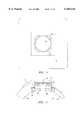
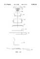
- FIG. 1is a top view of an insert within a void in a cast, in accordance with the present invention
- FIG. 2is a side cross-sectional view of an insert partially secured within a void in a cast
- FIG. 3is a top view of an insert having a plurality of tabs extending radially therefrom;
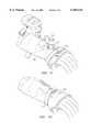
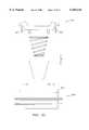
- FIG. 4is an exploded side view of an apparatus for mounting an ultrasound transducer
- FIG. 5is an enlarged side view of an assembled apparatus for mounting an ultrasound transducer
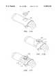
- FIG. 6is an enlarged side view of another embodiment of an assembled apparatus for mounting an ultrasound transducer
- FIG. 7is an exploded side view of another embodiment of an apparatus for mounting an ultrasound transducer
- FIG. 8is a side view of an assembled apparatus for mounting the ultrasound transducer of FIG. 7;
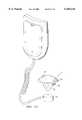
- FIG. 9is a perspective view of an insert secured in a cast ready to receive an ultrasound transducer head
- FIG. 10is a perspective view of a fully assembled apparatus for mounting an ultrasound transducer in a cast
- FIG. 11is a partial enlarged side view of another embodiment of an apparatus for mounting an ultrasound transducer
- FIGS. 12A-Dare various views of a cover illustrating alternative locking structure
- FIG. 13is a perspective view of another embodiment of a cover with alternative locking structure
- FIG. 14is a side view in cross-section of an apparatus for the installation of an insert adjacent a treatment location prior to installing a cast thereon;
- FIG. 15is a perspective view of a piece of casting tape and a sealed package therefor;
- FIGS. 16A-Care perspective views illustrating a system for mounting an ultrasound transducer receiving apparatus adjacent a treatment location
- FIGS. 17A-Care perspective views illustrating a system for mounting an ultrasound transducer receiving apparatus adjacent a treatment location in a cast;
- FIGS. 18A-Care perspective views illustrating a system for mounting an ultrasound transducer receiving apparatus adjacent a treatment location in a cast;
- FIG. 19is a plan view of an alternative embodiment of a casting tape
- FIGS. 20A-Care plan views of alternative embodiments of a strap for securing the apparatus for mounting an ultrasound transducer adjacent to a portion of the patient's body requiring treatment;
- FIG. 21is an enlarged cross-sectional side view of another embodiment of an assembled apparatus for mounting an ultrasound transducer
- FIG. 22is an exploded side view of the apparatus of FIG. 21;
- FIGS. 23A-Care top, side and bottom views of a snap plate
- FIG. 25is an exploded side view of an apparatus for mounting an ultrasound transducer having a cover with external locking structure.
- Insert 20is shown, positioned within a void 22 formed in a portion of a cast 24.
- Void 22has a substantially square shape and is delineated by the dashed lines.
- Insert 20is shown having a substantially circular periphery and a plurality of tabs 26 extending radially therefrom. Four tabs 26 are visible in FIG. 1. Additional tabs 26 are hidden by cast material in a plane beneath the visible tabs as will become apparent in FIG. 2.
- Insert 20preferably includes an axial bore within the substantially circular periphery to mount an ultrasound transducer to initiate a treatment, as will be discussed in further detail below.
- Insert 20is preferably formed of polypropylene.
- FIG. 2illustrates a side cross-sectional view of insert 20 within cast 24.
- a spacer 30Prior to placing insert 20 into void 22, a spacer 30 is placed within void 22.
- Spacer 30is configured to have a shape on its periphery which corresponds with the shape of void 22, and a hole in its center which corresponds to the shape of insert 20.
- Spacer 30is preferably formed of a medical grade felt or a similar material which will exhibit comfortable characteristics against a body portion of a patient, and may be fabricated in a plurality of layers so that the thickness can be adjusted depending on the thickness of cast 24.
- Spacer 30maintains insert 20 at a predetermined distance from the body portion 34 of a patient, to prevent window edema or a similar injury to the patient due to uneven pressure at a casted site.
- insert 20is partially inserted into the hole within spacer 30 and is supported thereon by at least one of the radially extending tabs 26.
- Tabs 26contain living hinges formed by a reduction in cross-section of the tabs 26 at a proximal end adjacent the bore of insert 20 which weakens tabs 26 at the hinge point, thus allowing them to bend freely.
- the living hingesprovide for lateral flexure of tabs 26 to enhance the ability to conform to varying angles which are a function of the anatomy of the patient.
- the living hingesallow insert 20 to be articulated to correct for other angular misalignments.
- Insert 20is secured within void 22 in cast 24 by weaving strips 32 of cast material between tabs 26. A plurality of layers of cast material strips 32 are placed around insert 20 until a desired thickness is achieved.
- the configuration of insert 20 having tabs 26allows the insert to be installed before or after the cast is installed.
- insert 20will be an integral part of the cast. Thus, any impact on the skin of the patient, which would otherwise be transferred through insert 20, will be minimized as it is absorbed by the cast.
- Insert 20may optionally include a hemispherical notch 36 in an upper end thereof to accommodate a cord extending from an ultrasound treatment head module while the module is positioned within the insert.
- a lower end 38 of insert 20is preferably concave to correspond to fit a convex body portion 34 of a patient, without impacting the skin which may cause edema or a similar injury.
- An ultrasound transmission-enhancing medium 28is preferably positioned within spacer 30 adjacent a treatment location to minimize or eliminate an air gap between an ultrasound transducer head module and a treatment location.
- the ultrasound transmission-enhancing medium 28is preferably a conductive gel bladder.
- the apparatus of the present inventionis configured to adapt to and fit within a substantially rectangular or square-shaped void in a cast as shown in a top view thereof in FIG. 3.
- the insert 20converts the void into a circular receptacle for receiving a corresponding circular-shaped ultrasound transducer head module.
- spacer 30is shown in cross-section, having a hole therein configured to insertably receive insert 20.
- Insert 20includes a plurality of tabs 26 and a concave lower end 38.
- Insert 20preferably includes at least one circumferential groove 40 in an upper portion thereof.
- the purpose of the circumferential groove 40is to enable the removal of at least one layer of insert 20 to adjust the height of insert 20 to correspond to a thickness of a cast.
- a means for facilitating removal of the medium from insert 20is provided.
- the means for facilitating removalis a tab 42 shown extending from medium 28.
- An ultrasound transducer head module 44is positioned adjacent ultrasound transmission-enhancing medium 28 within insert 20.
- Cord 50connects module 44 with electronic driving circuitry.
- Housing 46is then inserted in the upper portion of insert 20 to enclose the components within insert 20.
- a bias element 48extends from a bottom portion of housing 46.
- Bias element 48is preferably a conical helical spring.
- the conical helical springis advantageously configured to fully collapse within itself and will therefore require less space within insert 20.
- a conical helical springwill also maintain a uniform force on ultrasound transducer head module 44 and will allow module 44 to pivot to conform to the shape of transmission-enhancing medium 28.
- FIG. 5illustrates an enlarged side view of an assembled apparatus for mounting an ultrasound transducer in accordance with the present invention.
- This enlarged viewillustrates the living hinge 52 on tab 26 which allows for free lateral movement.
- spring 48in its compressed state urgingly biases transducer module 44 toward ultrasound transmission-enhancing medium 28.
- Rivet 60is provided to couple a strap 62 with cover 64 when the rivet is inserted through holes therein.
- Strap 62is designed to adjustably fit around a cast of a patient receiving ultrasound treatment and maintain a compressive force on spring 65 to ensure uniform and continuous pressure against ultrasound transducer head module 66 as it is positioned within insert 67.
- cover 64is configured to eliminate the need for the hemispherical notch 36 in insert 20 (FIG. 2), by providing an opening in cover 64 through which cord 68 passes.
- a padmust be placed within the insert to fill the void left by the transducer head module and maintain a constant pressure on the skin within the void in the cast which is equivalent to the pressure applied by the cast, to prevent edema.
- the padis preferably formed of a medical grade felt similar to spacer 30.
- the padmay also include a hard coating or disk on an upper surface thereof to provide a rigid surface adjacent bias element 48. The hard surface will prevent the bias element form forming an imprint in the pad and will maintain a constant force on the pad via the bias element.
- the padmay also include a tab, similar to tab 42, to facilitate removal of the pad from the insert. Strap 62 may be used to secure the pad within the insert and to apply a force to maintain a constant pressure.
- the apparatusmay also be secured to a treatment location that does not have a cast or other medical wrapping.
- FIG. 7illustrates an exploded view of such an apparatus
- FIG. 8illustrates a fully assembled view.
- the transducer head module 70is modified to have a hole 72 therein for receiving a rivet 74 which is inserted through a hole 76 in strap 78.
- Insert 80is preferably manufactured to a height corresponding to the combined thickness of the transducer head module 70 and the transmission-enhancing medium 82.
- insert 90is shown secured within a cast 92 of a patient requiring ultrasound treatment.
- Tab 94which is attached at its lower end to a transmission-enhancing medium is shown extending from insert 90.
- cover 98is placed over the top of insert 90 and strap 100 is adjusted to secure the entire apparatus in place.
- FIG. 11illustrates an embodiment of an apparatus for mounting an ultrasound transducer which features locking structure on the outside periphery of insert 110 for retaining a transducer head module within the insert.
- the locking structureincludes a circumferential ridge 112 on the outside periphery of insert 110 which is configured to engage at least one tab member 114 extending downward from an outer periphery of cover 116.
- tab member 114is formed of a resilient material such that it will flex outward as the ridge thereon is forced over ridge 112, and it will snap back into position after it moves beyond ridge 112.
- the locking structureadvantageously eliminates the need for a strap to secure the cover in place, as described above with other embodiments of the presently disclosed apparatus.
- Conical helical spring 118is held in contact with a lower surface of cover 116 by resilient housing 120.
- Resilient housing 120is designed to maintain spring 118 in its position under cover 116 while exhibiting resiliency corresponding to the compressive property of spring 118.
- Housing 120is secured to cover 116 by lock ring 122 which may be affixed to cover 116 by epoxy or any other means known to one having ordinary skill in the art.
- Housing 120is preferably formed of polyurethane having a thickness of approximately 0.01 inches.
- flanges 124are also illustrated in FIG. 11, are flanges 124. It is contemplated that flanges 124 may be a plurality of separate continuous circumferential flanges, a single circumferential flange having a spiral configuration around the periphery of insert 110 or at least one interrupted flange.
- FIGS. 12A-Dillustrates an alternative locking structure associated with cover 130 to removably engage cover 130 with insert 132.
- cover 130is illustrated locked within insert 132 by means of a hinged locking tab 134 on a first side of cover 130 and a protrusion 136 on a second side of cover 130.
- the portion of locking tab 134 which extends outwardly from cover 130is depressed to release protrusion 138 from a groove formed on the inner surface of insert 132.
- Cover 130may then be pivoted upward to disengage protrusion 136 from a corresponding groove in insert 132, and remove the cover.
- FIG. 25illustrates an embodiment of the presently disclosed mounting apparatus which employs external locking structure.
- cover 420includes external locking tabs 422 integrally formed therewith.
- the lower portions of tabs 422contact the circumferential lip 426 formed on the upper portion of insert 424.
- tabs 422are forced outwardly until the lower portions clear lip 426 and resiliently snap back to their original position, thereby locking cover 420 on insert 424.
- Cover 420may be removed from insert 424 by depressing the upper portions of tabs 422 in a direction toward the center of cover 420, and simultaneously lifting cover 420 off insert 424.
- cover 130includes a conical helical spring 140 which is held in contact with a lower surface of cover 130 by a resilient housing 142.
- Resilient housing 142is designed to maintain spring 140 in its position under cover 130 while exhibiting resiliency corresponding to the compressive property of spring 140.
- Housing 142is secured to cover 130 by a lock ring which may be affixed to cover 130 by epoxy or any other means known to one having ordinary skill in the art.
- FIG. 13illustrates a perspective view of cover 150 having locking structure similar to that which was described above with reference to FIGS. 12A-D.
- Cover 150differs from cover 130 in that cover 150 has two locking tabs 154 for locking the cover within an insert.
- Protrusion 158is similarly formed on locking tab 154 to engage a groove on the inner surface of an insert.
- an ultrasound treatment module with treatment head 160is also shown in FIG. 13.
- conical helical spring 162is connected to a lower surface of cover 150 to bias treatment head 160 in a direction toward a treatment site.
- FIG. 14illustrates an apparatus 170 for the installation of an insert adjacent a treatment location prior to installing a cast thereon for insertably receiving an ultrasound transducer treatment head.
- Apparatus 170comprises an insert 172 having radial tabs 174 on an outer periphery thereof, a spacer 176 to maintain insert 172 a predetermined distance away from the skin of the patient, and padding portion 178 which wraps around the intended treatment location.
- FIGS. 16A-CThe pre-cast installation of apparatus 170 will now be described with reference to FIGS. 16A-C.
- a stocking 180is typically placed over the portion of the patient's body over which a cast will be installed.
- a hole 182is then cut in stocking 180 at the precise location for receiving ultrasound treatment.
- Apparatus 170is then positioned over stocking 18 such that insert 172 is adjacent hole 182.
- padding 178is then draped around the intended treatment location and apparatus 170 is secured in place by a piece of casting tape 184.
- casting tape 184is preferably supplied having a pre-cut hole therein and is stored in a sealed package 186 to maintain sterile conditions.
- Casting tape 184advantageously provides structural strength to apparatus 170 and simplifies the main cast wrapping. Referring now to FIG. 16C, apparatus 170 is shown secured within a main cast 188, ready for a cover 190 or an ultrasound transducer head module as discussed above.
- FIG. 17A-Ca system for installing an apparatus for receiving an ultrasound treatment head module in a cast which has already been installed about a treatment location is illustrated.
- a felt pad 200is provided to be placed within a void 204 cut in a cast 202.
- Felt pad 200is dimensioned corresponding to the thickness of cast 202.
- felt pad 200may initially be used as a template for cutting void 204 in cast 202.
- Felt pad 200is then installed within void 204.
- felt pad 200is shown within void 204 adjacent a treatment location on a patient and apparatus 206 is positioned such that insert 208 fits within the hole in felt pad 200.
- Padding 210is then draped around cast 202.
- apparatus 206is then secured in place with a precut piece of casting tape 212 which is configured and dimensioned to fit over insert 208.
- Apparatus 206 and tape 212may then be further secured in place by strips of 1" wide casting tape 214.
- a cover 216 or ultrasound transducermay then be placed in insert 208.
- FIGS. 18A-Cillustrate a system for installing an apparatus for receiving an ultrasound treatment head module in a cast while utilizing an alternative embodiment to the precut piece of casting tape 212 described above.
- the alternative embodimentis illustrated in FIG. 19 and is designated as numeral 220.
- Casting tape 220has a hole 222 formed therein which is dimensioned to fit over an insert 224, and further includes a pair of legs 225 extending laterally from either side.
- FIGS. 18A-Cbegin with using a felt pad 226 as a template to cut a void 228 in a cast 230.
- the voidis cut and felt pad 226 is placed within void 228, and an apparatus including insert 224 for insertably receiving a transducer head module is draped over cast 230 such that insert 224 is positioned over a corresponding hole in felt pad 226.
- casting tape 220is placed over insert 224 and legs 225 are wrapped around cast 230 to secure insert 224 in place.
- a cover 232 or ultrasound transducermay then be placed in insert 224.
- the apparatusmay include padding, similar to that which is shown as numeral 210 in FIG. 17B, wherein the padding is configured in a shape similar to casting tape 220.
- the legs of the paddingmay then include a means for fixing the apparatus securely in position; such as, for example, VELCROTM, adhesive, plastic ties or a buckle.
- Straps 250, 260 and 270 illustrated in FIGS. 20A-C, respectively,may be utilized therefor.
- Straps 250, 260 and 270are preferably formed of a Neoprene material and are preferably 3/32 inches thick and twenty-eight inches long (although they may be made longer, shorter, thicker or narrower to suit a particular requirement).
- Each of straps 250 and 270define a hole 252 and 272, respectively, which is configured and dimensioned to stretch and fit around the outer periphery-of an insert.
- straps 250 and 260each include two VELCROTM hook patches 254 and 264, respectively, attached thereto.
- Patches 254 and 264are configured to be compatible with loops formed in the neoprene strap to thereby facilitate virtually unlimited adjustability of the strap as it is placed around the patient.
- a single loopis attached to an end of strap 250.
- Strap 260is secured in a similar fashion. Strap 260 does not include a hole dimensioned to fit around the outer periphery of an insert. Rather, strap 260 includes an additional VELCROTM patch 262 for attachment to a mating patch which is secured to a surface of an ultrasound transducer.
- Strap 270illustrated in FIG. 20C, is alternatively provided with a slider bar loop 274 configuration to insertably receive end portion 276.
- end 276is woven through slider bar loop 274 and pulled taut as required. The strap is then held in place between the teeth on the slider bar and loop.
- FIG. 21a side cross-sectional view of insert 300 is illustrated within cast 302.
- a spacer 314Prior to placing insert 300 into a void in cast 302, a spacer 314 is placed within the void.
- Spacer 314is configured to have a shape on its periphery which corresponds with the shape of a void in the cast, and a hole in its center which corresponds to the shape of insert 300.
- Spacer 314is preferably formed of a medical grade felt or similar material which will exhibit comfortable characteristics against a body portion of a patient, and may be fabricated in a plurality of layers so that the thickness can be adjusted depending on the thickness of cast 302.
- Spacer 314maintains insert 300 at a predetermined distance from the body portion of a patent.
- snap plate 312which will be discussed in further detail below, is placed over spacer 314 and defines a hole therein which is dimensioned corresponding to the hole in spacer 314.
- Snap plate 312is configured to bias insert 300 away from the patient's body and to flex to prevent damage to the patient in case the insert is subject to an external force.
- Insert 300is secured within the void in cast 302 by weaving strips 324 of cast material between tabs 326. A plurality of layers of cast material strips 324 are placed around insert 300 until a desired thickness is achieved.
- the configuration of insert 300 having tabs 326allows the insert to be installed before or after the cast is installed.
- insert 300will be an integral part of the cast. Thus, any impact on the skin of the patient, which would otherwise be transferred through insert 300, will be minimized as it is absorbed by the cast.
- An ultrasound transducer head module 320may then be positioned within insert 300.
- Cover 304having locking tab assembly 310, is then inserted in the upper portion of insert 300 to enclose the components within insert 300.
- a bias element 306extends from a bottom portion of cover 304.
- Bias element 306is preferably a conical helical spring and is held in contact with a lower surface of cover 304 by resilient housing 308.
- a modular field reconfigurable kithaving components which facilitate the installation of a transducer head module adjacent a portion of a patient's body while the cast is being installed, after the cast is installed, or at a location having no cast.
- the kitincludes a strap 322 which is primarily used in the no-cast application; a felt plug 318 which is inserted within insert 300 while the transducer head module is not in use; a foam pad 316 which is also primarily used during the no-cast application; a felt pad 314; a snap plate 312 which may alternatively be connected to insert 300; an insert 300; a locking tab assembly 310; a spring housing 308; a spring 306; and a cover 304.
- a single kitis provided which includes all of the necessary components for mounting an ultrasound transducer adjacent a portion of the patient's body, regardless of whether a cast will be installed in the future, already exists, or will not be installed at all.
- FIGS. 23A-Cillustrate top, side and bottom views, respectively, of snap plate 312.
- Snap plate 312defines a hole 330 therein which is dimensioned in accordance with the outside diameter of insert 300.
- snap plate 312includes two raised portions 332 located on either side of hole 330. The two raised portions 332 provide a flat horizontal platform for insert 300 to rest upon.
- snap plate 312is contoured to attain a concave lower surface which will advantageously fit around a cast of a patient. The contour also gives snap plate 312 the ability to flex in response to a force exerted on insert 300 which is transmitted therethrough to an upper portion of the snap plate. As illustrated in FIGS.
- Snap plate 312is preferably formed of fire retardant ABS or an equivalent material.
- FIGS. 24A and Billustrate an embodiment of insert 400 which has the ability to be raised or lowered within the void in the cast.
- Insert 400contains an inner portion 402 and an outer portion 404.
- Inner portion 402defines a longitudinal bore therethrough for insertably receiving the several components as discussed above.
- the outer periphery of inner portion 402includes a plurality of threads, as indicated by the dashed lines, which engage a corresponding plurality of threads on an inner surface of outer portion 404.
- the outer periphery of outer portion 404includes flanges 406, which, as discussed above with reference to FIG. 21, may be secured to cast 410 by weaving a plurality of cast material strips 408 therethrough.
- flanges 406which, as discussed above with reference to FIG. 21, may be secured to cast 410 by weaving a plurality of cast material strips 408 therethrough.
Landscapes
- Health & Medical Sciences (AREA)
- Engineering & Computer Science (AREA)
- Biomedical Technology (AREA)
- Nuclear Medicine, Radiotherapy & Molecular Imaging (AREA)
- Radiology & Medical Imaging (AREA)
- Life Sciences & Earth Sciences (AREA)
- Animal Behavior & Ethology (AREA)
- General Health & Medical Sciences (AREA)
- Public Health (AREA)
- Veterinary Medicine (AREA)
- Physics & Mathematics (AREA)
- Acoustics & Sound (AREA)
- Multimedia (AREA)
- Surgical Instruments (AREA)
- Dental Tools And Instruments Or Auxiliary Dental Instruments (AREA)
- Orthopedics, Nursing, And Contraception (AREA)
- Transducers For Ultrasonic Waves (AREA)
- Percussion Or Vibration Massage (AREA)
- Measurement Of Velocity Or Position Using Acoustic Or Ultrasonic Waves (AREA)
Abstract
Description
Claims (28)
Priority Applications (9)
| Application Number | Priority Date | Filing Date | Title |
|---|---|---|---|
| US09/040,155US6165144A (en) | 1998-03-17 | 1998-03-17 | Apparatus and method for mounting an ultrasound transducer |
| EP99912609AEP1064052B1 (en) | 1998-03-17 | 1999-03-17 | Apparatus and method for mounting an ultrasound transducer |
| ES99912609TES2228025T3 (en) | 1998-03-17 | 1999-03-17 | APPLIANCE AND PROCEDURE FOR ASSEMBLING AN ULTRASOUND TRANSDUCER. |
| AU30951/99AAU743769B2 (en) | 1998-03-17 | 1999-03-17 | Apparatus and method for mounting an ultrasound transducer |
| DE69920417TDE69920417T2 (en) | 1998-03-17 | 1999-03-17 | DEVICE AND METHOD FOR FIXING AN ULTRASOUND TRANSFORMER |
| AT99912609TATE276798T1 (en) | 1998-03-17 | 1999-03-17 | DEVICE AND METHOD FOR MOUNTING AN ULTRASONIC TRANSDUCER |
| JP2000536441AJP4224211B2 (en) | 1998-03-17 | 1999-03-17 | Apparatus and method for attaching an ultrasonic transducer |
| CA002323971ACA2323971C (en) | 1998-03-17 | 1999-03-17 | Apparatus and method for mounting an ultrasound transducer |
| PCT/US1999/005803WO1999047208A1 (en) | 1998-03-17 | 1999-03-17 | Apparatus and method for mounting an ultrasound transducer |
Applications Claiming Priority (1)
| Application Number | Priority Date | Filing Date | Title |
|---|---|---|---|
| US09/040,155US6165144A (en) | 1998-03-17 | 1998-03-17 | Apparatus and method for mounting an ultrasound transducer |
Publications (1)
| Publication Number | Publication Date |
|---|---|
| US6165144Atrue US6165144A (en) | 2000-12-26 |
Family
ID=21909419
Family Applications (1)
| Application Number | Title | Priority Date | Filing Date |
|---|---|---|---|
| US09/040,155Expired - LifetimeUS6165144A (en) | 1998-03-17 | 1998-03-17 | Apparatus and method for mounting an ultrasound transducer |
Country Status (9)
| Country | Link |
|---|---|
| US (1) | US6165144A (en) |
| EP (1) | EP1064052B1 (en) |
| JP (1) | JP4224211B2 (en) |
| AT (1) | ATE276798T1 (en) |
| AU (1) | AU743769B2 (en) |
| CA (1) | CA2323971C (en) |
| DE (1) | DE69920417T2 (en) |
| ES (1) | ES2228025T3 (en) |
| WO (1) | WO1999047208A1 (en) |
Cited By (74)
| Publication number | Priority date | Publication date | Assignee | Title |
|---|---|---|---|---|
| US6406443B1 (en)* | 1999-06-14 | 2002-06-18 | Exogen, Inc. | Self-contained ultrasound applicator |
| US6585647B1 (en) | 1998-07-21 | 2003-07-01 | Alan A. Winder | Method and means for synthetic structural imaging and volume estimation of biological tissue organs |
| US20040015105A1 (en)* | 2001-06-26 | 2004-01-22 | Masaya Ito | Apparatus and method for treating joint disease |
| US20040064051A1 (en)* | 2002-09-30 | 2004-04-01 | Talish Roger J. | Ultrasound transducer coupling apparatus |
| US6932308B2 (en) | 2000-10-25 | 2005-08-23 | Exogen, Inc. | Transducer mounting assembly |
| US20060123043A1 (en)* | 2004-12-02 | 2006-06-08 | Samsung Electronics Co., Ltd. | File system path processing device and method |
| US7108663B2 (en) | 1997-02-06 | 2006-09-19 | Exogen, Inc. | Method and apparatus for cartilage growth stimulation |
| US7211060B1 (en) | 1998-05-06 | 2007-05-01 | Exogen, Inc. | Ultrasound bandages |
| US7410469B1 (en) | 1999-05-21 | 2008-08-12 | Exogen, Inc. | Apparatus and method for ultrasonically and electromagnetically treating tissue |
| US7429248B1 (en) | 2001-08-09 | 2008-09-30 | Exogen, Inc. | Method and apparatus for controlling acoustic modes in tissue healing applications |
| US7429249B1 (en) | 1999-06-14 | 2008-09-30 | Exogen, Inc. | Method for cavitation-induced tissue healing with low intensity ultrasound |
| US20090189488A1 (en)* | 2008-01-29 | 2009-07-30 | Hyde Park Electronics Llc | Ultrasonic transducer for a proximity sensor |
| US7628764B2 (en) | 1997-02-14 | 2009-12-08 | Exogen, Inc. | Ultrasonic treatment for wounds |
| US20100152624A1 (en)* | 2005-11-07 | 2010-06-17 | Smith & Nephew, Inc. | Apparatus and method for mounting a therapeutic device |
| US7789841B2 (en) | 1997-02-06 | 2010-09-07 | Exogen, Inc. | Method and apparatus for connective tissue treatment |
| US20100309018A1 (en)* | 2008-01-29 | 2010-12-09 | Schneider Electric USA, Inc. | Ultrasonic transducer for a proximity sensor |
| US8388546B2 (en) | 2006-10-23 | 2013-03-05 | Bard Access Systems, Inc. | Method of locating the tip of a central venous catheter |
| US8388541B2 (en) | 2007-11-26 | 2013-03-05 | C. R. Bard, Inc. | Integrated system for intravascular placement of a catheter |
| US8437833B2 (en) | 2008-10-07 | 2013-05-07 | Bard Access Systems, Inc. | Percutaneous magnetic gastrostomy |
| WO2012021542A3 (en)* | 2010-08-09 | 2013-05-23 | C.R. Bard, Inc. | Support and cover structures for an ultrasound probe head |
| US8478382B2 (en) | 2008-02-11 | 2013-07-02 | C. R. Bard, Inc. | Systems and methods for positioning a catheter |
| US8512256B2 (en) | 2006-10-23 | 2013-08-20 | Bard Access Systems, Inc. | Method of locating the tip of a central venous catheter |
| USD699359S1 (en) | 2011-08-09 | 2014-02-11 | C. R. Bard, Inc. | Ultrasound probe head |
| US8781555B2 (en) | 2007-11-26 | 2014-07-15 | C. R. Bard, Inc. | System for placement of a catheter including a signal-generating stylet |
| US8784336B2 (en) | 2005-08-24 | 2014-07-22 | C. R. Bard, Inc. | Stylet apparatuses and methods of manufacture |
| US8801693B2 (en) | 2010-10-29 | 2014-08-12 | C. R. Bard, Inc. | Bioimpedance-assisted placement of a medical device |
| US8849382B2 (en) | 2007-11-26 | 2014-09-30 | C. R. Bard, Inc. | Apparatus and display methods relating to intravascular placement of a catheter |
| USD724745S1 (en) | 2011-08-09 | 2015-03-17 | C. R. Bard, Inc. | Cap for an ultrasound probe |
| US9125578B2 (en) | 2009-06-12 | 2015-09-08 | Bard Access Systems, Inc. | Apparatus and method for catheter navigation and tip location |
| US20150272545A1 (en)* | 2014-03-25 | 2015-10-01 | Seiko Epson Corporation | Ultrasonic measuring device |
| US9211107B2 (en) | 2011-11-07 | 2015-12-15 | C. R. Bard, Inc. | Ruggedized ultrasound hydrogel insert |
| US9339206B2 (en) | 2009-06-12 | 2016-05-17 | Bard Access Systems, Inc. | Adaptor for endovascular electrocardiography |
| US9445734B2 (en) | 2009-06-12 | 2016-09-20 | Bard Access Systems, Inc. | Devices and methods for endovascular electrography |
| US9456766B2 (en) | 2007-11-26 | 2016-10-04 | C. R. Bard, Inc. | Apparatus for use with needle insertion guidance system |
| US9492097B2 (en) | 2007-11-26 | 2016-11-15 | C. R. Bard, Inc. | Needle length determination and calibration for insertion guidance system |
| US9504471B2 (en) | 2013-09-25 | 2016-11-29 | Cybersonics, Inc. | Ultrasonic generator systems and methods |
| US9521961B2 (en) | 2007-11-26 | 2016-12-20 | C. R. Bard, Inc. | Systems and methods for guiding a medical instrument |
| US9532724B2 (en) | 2009-06-12 | 2017-01-03 | Bard Access Systems, Inc. | Apparatus and method for catheter navigation using endovascular energy mapping |
| US9554716B2 (en) | 2007-11-26 | 2017-01-31 | C. R. Bard, Inc. | Insertion guidance system for needles and medical components |
| US20170027595A1 (en)* | 2004-09-20 | 2017-02-02 | P Tech, Llc | Acoustic therapy device |
| US9636031B2 (en) | 2007-11-26 | 2017-05-02 | C.R. Bard, Inc. | Stylets for use with apparatus for intravascular placement of a catheter |
| US9649048B2 (en) | 2007-11-26 | 2017-05-16 | C. R. Bard, Inc. | Systems and methods for breaching a sterile field for intravascular placement of a catheter |
| US9839372B2 (en) | 2014-02-06 | 2017-12-12 | C. R. Bard, Inc. | Systems and methods for guidance and placement of an intravascular device |
| US9901753B2 (en) | 2009-08-26 | 2018-02-27 | The Regents Of The University Of Michigan | Ultrasound lithotripsy and histotripsy for using controlled bubble cloud cavitation in fractionating urinary stones |
| US9901714B2 (en) | 2008-08-22 | 2018-02-27 | C. R. Bard, Inc. | Catheter assembly including ECG sensor and magnetic assemblies |
| US9943708B2 (en) | 2009-08-26 | 2018-04-17 | Histosonics, Inc. | Automated control of micromanipulator arm for histotripsy prostate therapy while imaging via ultrasound transducers in real time |
| US10046139B2 (en) | 2010-08-20 | 2018-08-14 | C. R. Bard, Inc. | Reconfirmation of ECG-assisted catheter tip placement |
| US10071266B2 (en) | 2011-08-10 | 2018-09-11 | The Regents Of The University Of Michigan | Lesion generation through bone using histotripsy therapy without aberration correction |
| EP2844343B1 (en)* | 2012-04-30 | 2018-11-21 | The Regents Of The University Of Michigan | Ultrasound transducer manufacturing using rapid-prototyping method |
| US10219815B2 (en) | 2005-09-22 | 2019-03-05 | The Regents Of The University Of Michigan | Histotripsy for thrombolysis |
| US10293187B2 (en) | 2013-07-03 | 2019-05-21 | Histosonics, Inc. | Histotripsy excitation sequences optimized for bubble cloud formation using shock scattering |
| US20190154634A1 (en)* | 2016-08-11 | 2019-05-23 | Novitech Inc. | Magnetizers for pigging tools |
| US10349890B2 (en) | 2015-06-26 | 2019-07-16 | C. R. Bard, Inc. | Connector interface for ECG-based catheter positioning system |
| US10449330B2 (en) | 2007-11-26 | 2019-10-22 | C. R. Bard, Inc. | Magnetic element-equipped needle assemblies |
| US10524691B2 (en) | 2007-11-26 | 2020-01-07 | C. R. Bard, Inc. | Needle assembly including an aligned magnetic element |
| US10751509B2 (en) | 2007-11-26 | 2020-08-25 | C. R. Bard, Inc. | Iconic representations for guidance of an indwelling medical device |
| CN111658034A (en)* | 2020-07-13 | 2020-09-15 | 牛鸣 | Distractor in knee joint replacement |
| US10780298B2 (en) | 2013-08-22 | 2020-09-22 | The Regents Of The University Of Michigan | Histotripsy using very short monopolar ultrasound pulses |
| US10820885B2 (en) | 2012-06-15 | 2020-11-03 | C. R. Bard, Inc. | Apparatus and methods for detection of a removable cap on an ultrasound probe |
| US10973584B2 (en) | 2015-01-19 | 2021-04-13 | Bard Access Systems, Inc. | Device and method for vascular access |
| US10992079B2 (en) | 2018-10-16 | 2021-04-27 | Bard Access Systems, Inc. | Safety-equipped connection systems and methods thereof for establishing electrical connections |
| US11000207B2 (en) | 2016-01-29 | 2021-05-11 | C. R. Bard, Inc. | Multiple coil system for tracking a medical device |
| US11058399B2 (en) | 2012-10-05 | 2021-07-13 | The Regents Of The University Of Michigan | Bubble-induced color doppler feedback during histotripsy |
| CN113289277A (en)* | 2021-06-28 | 2021-08-24 | 中国人民解放军陆军特色医学中心 | Fixing device for ultrasonic instrument treatment probe |
| US11103213B2 (en) | 2009-10-08 | 2021-08-31 | C. R. Bard, Inc. | Spacers for use with an ultrasound probe |
| US11135454B2 (en) | 2015-06-24 | 2021-10-05 | The Regents Of The University Of Michigan | Histotripsy therapy systems and methods for the treatment of brain tissue |
| CN113811237A (en)* | 2019-05-14 | 2021-12-17 | 皇家飞利浦有限公司 | Assembly for mounting a sensor on skin |
| CN114795624A (en)* | 2022-05-24 | 2022-07-29 | 浙江大学 | Combination of shoulder support and brace for promoting tendon and bone healing through ultrasound |
| US11432900B2 (en) | 2013-07-03 | 2022-09-06 | Histosonics, Inc. | Articulating arm limiter for cavitational ultrasound therapy system |
| US11648424B2 (en) | 2018-11-28 | 2023-05-16 | Histosonics Inc. | Histotripsy systems and methods |
| US11813485B2 (en) | 2020-01-28 | 2023-11-14 | The Regents Of The University Of Michigan | Systems and methods for histotripsy immunosensitization |
| USD1076106S1 (en)* | 2021-03-23 | 2025-05-20 | Lazaro Eduardo Hernandez | Ultrasound transducer probe holder |
| US12318636B2 (en) | 2022-10-28 | 2025-06-03 | Histosonics, Inc. | Histotripsy systems and methods |
| US12343568B2 (en) | 2020-08-27 | 2025-07-01 | The Regents Of The University Of Michigan | Ultrasound transducer with transmit-receive capability for histotripsy |
Families Citing this family (5)
| Publication number | Priority date | Publication date | Assignee | Title |
|---|---|---|---|---|
| CA2648214C (en)* | 2006-04-07 | 2015-06-30 | Smith & Nephew, Inc. | Controlling acoustic modes in tissue healing applications |
| JP5566195B2 (en)* | 2010-06-11 | 2014-08-06 | 伊藤超短波株式会社 | Ultrasonic therapy device and ultrasonic therapy system |
| JP5950547B2 (en)* | 2011-11-28 | 2016-07-13 | 伊藤超短波株式会社 | Treatment device |
| CN110711323B (en)* | 2019-11-22 | 2024-04-30 | 南京光声超构材料研究院有限公司 | Self-adaptive focusing ultrasonic treatment head |
| CN115985280B (en)* | 2022-11-30 | 2025-10-03 | 南京理工大学 | An ultra-broadband transmission acoustic metamaterial |
Citations (11)
| Publication number | Priority date | Publication date | Assignee | Title |
|---|---|---|---|---|
| US4296753A (en)* | 1978-09-19 | 1981-10-27 | U.S. Philips Corporation | Support for a transducer for emitting and/or receiving ultrasonic signals in a given angular sector |
| US4556066A (en)* | 1983-11-04 | 1985-12-03 | The Kendall Company | Ultrasound acoustical coupling pad |
| EP0331348A1 (en)* | 1988-02-29 | 1989-09-06 | Edward H. M.D. Hon | Ultrasound transducer holder |
| US4947853A (en)* | 1985-09-26 | 1990-08-14 | Hon Edward H | Sensor support base and method of application |
| US5003965A (en)* | 1988-09-14 | 1991-04-02 | Meditron Corporation | Medical device for ultrasonic treatment of living tissue and/or cells |
| US5186162A (en)* | 1988-09-14 | 1993-02-16 | Interpore Orthopaedics, Inc. | Ultrasonic transducer device for treatment of living tissue and/or cells |
| US5211160A (en)* | 1988-09-14 | 1993-05-18 | Interpore Orthopaedics, Inc. | Ultrasonic orthopedic treatment head and body-mounting means therefor |
| US5520612A (en)* | 1994-12-30 | 1996-05-28 | Exogen, Inc. | Acoustic system for bone-fracture therapy |
| US5556372A (en)* | 1995-02-15 | 1996-09-17 | Exogen, Inc. | Apparatus for ultrasonic bone treatment |
| US5730705A (en)* | 1995-06-12 | 1998-03-24 | Talish; Roger J. | Ultrasonic treatment for bony ingrowth |
| US5904659A (en)* | 1997-02-14 | 1999-05-18 | Exogen, Inc. | Ultrasonic treatment for wounds |
- 1998
- 1998-03-17USUS09/040,155patent/US6165144A/ennot_activeExpired - Lifetime
- 1999
- 1999-03-17ESES99912609Tpatent/ES2228025T3/ennot_activeExpired - Lifetime
- 1999-03-17WOPCT/US1999/005803patent/WO1999047208A1/enactiveIP Right Grant
- 1999-03-17EPEP99912609Apatent/EP1064052B1/ennot_activeExpired - Lifetime
- 1999-03-17ATAT99912609Tpatent/ATE276798T1/ennot_activeIP Right Cessation
- 1999-03-17JPJP2000536441Apatent/JP4224211B2/ennot_activeExpired - Fee Related
- 1999-03-17CACA002323971Apatent/CA2323971C/ennot_activeExpired - Fee Related
- 1999-03-17DEDE69920417Tpatent/DE69920417T2/ennot_activeExpired - Lifetime
- 1999-03-17AUAU30951/99Apatent/AU743769B2/ennot_activeCeased
Patent Citations (11)
| Publication number | Priority date | Publication date | Assignee | Title |
|---|---|---|---|---|
| US4296753A (en)* | 1978-09-19 | 1981-10-27 | U.S. Philips Corporation | Support for a transducer for emitting and/or receiving ultrasonic signals in a given angular sector |
| US4556066A (en)* | 1983-11-04 | 1985-12-03 | The Kendall Company | Ultrasound acoustical coupling pad |
| US4947853A (en)* | 1985-09-26 | 1990-08-14 | Hon Edward H | Sensor support base and method of application |
| EP0331348A1 (en)* | 1988-02-29 | 1989-09-06 | Edward H. M.D. Hon | Ultrasound transducer holder |
| US5003965A (en)* | 1988-09-14 | 1991-04-02 | Meditron Corporation | Medical device for ultrasonic treatment of living tissue and/or cells |
| US5186162A (en)* | 1988-09-14 | 1993-02-16 | Interpore Orthopaedics, Inc. | Ultrasonic transducer device for treatment of living tissue and/or cells |
| US5211160A (en)* | 1988-09-14 | 1993-05-18 | Interpore Orthopaedics, Inc. | Ultrasonic orthopedic treatment head and body-mounting means therefor |
| US5520612A (en)* | 1994-12-30 | 1996-05-28 | Exogen, Inc. | Acoustic system for bone-fracture therapy |
| US5556372A (en)* | 1995-02-15 | 1996-09-17 | Exogen, Inc. | Apparatus for ultrasonic bone treatment |
| US5730705A (en)* | 1995-06-12 | 1998-03-24 | Talish; Roger J. | Ultrasonic treatment for bony ingrowth |
| US5904659A (en)* | 1997-02-14 | 1999-05-18 | Exogen, Inc. | Ultrasonic treatment for wounds |
Non-Patent Citations (1)
| Title |
|---|
| International Search Report dated Jul. 6, 1999.* |
Cited By (135)
| Publication number | Priority date | Publication date | Assignee | Title |
|---|---|---|---|---|
| US7108663B2 (en) | 1997-02-06 | 2006-09-19 | Exogen, Inc. | Method and apparatus for cartilage growth stimulation |
| US8123707B2 (en) | 1997-02-06 | 2012-02-28 | Exogen, Inc. | Method and apparatus for connective tissue treatment |
| US7789841B2 (en) | 1997-02-06 | 2010-09-07 | Exogen, Inc. | Method and apparatus for connective tissue treatment |
| US7628764B2 (en) | 1997-02-14 | 2009-12-08 | Exogen, Inc. | Ultrasonic treatment for wounds |
| US7211060B1 (en) | 1998-05-06 | 2007-05-01 | Exogen, Inc. | Ultrasound bandages |
| US6585647B1 (en) | 1998-07-21 | 2003-07-01 | Alan A. Winder | Method and means for synthetic structural imaging and volume estimation of biological tissue organs |
| US7410469B1 (en) | 1999-05-21 | 2008-08-12 | Exogen, Inc. | Apparatus and method for ultrasonically and electromagnetically treating tissue |
| US6406443B1 (en)* | 1999-06-14 | 2002-06-18 | Exogen, Inc. | Self-contained ultrasound applicator |
| US7429249B1 (en) | 1999-06-14 | 2008-09-30 | Exogen, Inc. | Method for cavitation-induced tissue healing with low intensity ultrasound |
| US6932308B2 (en) | 2000-10-25 | 2005-08-23 | Exogen, Inc. | Transducer mounting assembly |
| US20040015105A1 (en)* | 2001-06-26 | 2004-01-22 | Masaya Ito | Apparatus and method for treating joint disease |
| US7429248B1 (en) | 2001-08-09 | 2008-09-30 | Exogen, Inc. | Method and apparatus for controlling acoustic modes in tissue healing applications |
| WO2004030762A1 (en) | 2002-09-30 | 2004-04-15 | Exogen, Inc. | Ultrasound transducer coupling apparatus |
| US20040064051A1 (en)* | 2002-09-30 | 2004-04-01 | Talish Roger J. | Ultrasound transducer coupling apparatus |
| US20170027595A1 (en)* | 2004-09-20 | 2017-02-02 | P Tech, Llc | Acoustic therapy device |
| US11534187B2 (en) | 2004-09-20 | 2022-12-27 | P Tech, Llc | Acoustic therapy device |
| US20060123043A1 (en)* | 2004-12-02 | 2006-06-08 | Samsung Electronics Co., Ltd. | File system path processing device and method |
| US11207496B2 (en) | 2005-08-24 | 2021-12-28 | C. R. Bard, Inc. | Stylet apparatuses and methods of manufacture |
| US8784336B2 (en) | 2005-08-24 | 2014-07-22 | C. R. Bard, Inc. | Stylet apparatuses and methods of manufacture |
| US10004875B2 (en) | 2005-08-24 | 2018-06-26 | C. R. Bard, Inc. | Stylet apparatuses and methods of manufacture |
| US12303152B2 (en) | 2005-09-22 | 2025-05-20 | The Regents Of The University Of Michigan | Histotripsy for thrombolysis |
| US11364042B2 (en) | 2005-09-22 | 2022-06-21 | The Regents Of The University Of Michigan | Histotripsy for thrombolysis |
| US10219815B2 (en) | 2005-09-22 | 2019-03-05 | The Regents Of The University Of Michigan | Histotripsy for thrombolysis |
| US11701134B2 (en) | 2005-09-22 | 2023-07-18 | The Regents Of The University Of Michigan | Histotripsy for thrombolysis |
| US12150661B2 (en) | 2005-09-22 | 2024-11-26 | The Regents Of The University Of Michigan | Histotripsy for thrombolysis |
| US20100152624A1 (en)* | 2005-11-07 | 2010-06-17 | Smith & Nephew, Inc. | Apparatus and method for mounting a therapeutic device |
| US9833169B2 (en) | 2006-10-23 | 2017-12-05 | Bard Access Systems, Inc. | Method of locating the tip of a central venous catheter |
| US8388546B2 (en) | 2006-10-23 | 2013-03-05 | Bard Access Systems, Inc. | Method of locating the tip of a central venous catheter |
| US8512256B2 (en) | 2006-10-23 | 2013-08-20 | Bard Access Systems, Inc. | Method of locating the tip of a central venous catheter |
| US8858455B2 (en) | 2006-10-23 | 2014-10-14 | Bard Access Systems, Inc. | Method of locating the tip of a central venous catheter |
| US9345422B2 (en) | 2006-10-23 | 2016-05-24 | Bard Acess Systems, Inc. | Method of locating the tip of a central venous catheter |
| US8774907B2 (en) | 2006-10-23 | 2014-07-08 | Bard Access Systems, Inc. | Method of locating the tip of a central venous catheter |
| US9265443B2 (en) | 2006-10-23 | 2016-02-23 | Bard Access Systems, Inc. | Method of locating the tip of a central venous catheter |
| US9549685B2 (en) | 2007-11-26 | 2017-01-24 | C. R. Bard, Inc. | Apparatus and display methods relating to intravascular placement of a catheter |
| US10342575B2 (en) | 2007-11-26 | 2019-07-09 | C. R. Bard, Inc. | Apparatus for use with needle insertion guidance system |
| US10524691B2 (en) | 2007-11-26 | 2020-01-07 | C. R. Bard, Inc. | Needle assembly including an aligned magnetic element |
| US10449330B2 (en) | 2007-11-26 | 2019-10-22 | C. R. Bard, Inc. | Magnetic element-equipped needle assemblies |
| US11779240B2 (en) | 2007-11-26 | 2023-10-10 | C. R. Bard, Inc. | Systems and methods for breaching a sterile field for intravascular placement of a catheter |
| US11707205B2 (en) | 2007-11-26 | 2023-07-25 | C. R. Bard, Inc. | Integrated system for intravascular placement of a catheter |
| US8849382B2 (en) | 2007-11-26 | 2014-09-30 | C. R. Bard, Inc. | Apparatus and display methods relating to intravascular placement of a catheter |
| US8781555B2 (en) | 2007-11-26 | 2014-07-15 | C. R. Bard, Inc. | System for placement of a catheter including a signal-generating stylet |
| US10966630B2 (en) | 2007-11-26 | 2021-04-06 | C. R. Bard, Inc. | Integrated system for intravascular placement of a catheter |
| US10602958B2 (en) | 2007-11-26 | 2020-03-31 | C. R. Bard, Inc. | Systems and methods for guiding a medical instrument |
| US11134915B2 (en) | 2007-11-26 | 2021-10-05 | C. R. Bard, Inc. | System for placement of a catheter including a signal-generating stylet |
| US10105121B2 (en) | 2007-11-26 | 2018-10-23 | C. R. Bard, Inc. | System for placement of a catheter including a signal-generating stylet |
| US9456766B2 (en) | 2007-11-26 | 2016-10-04 | C. R. Bard, Inc. | Apparatus for use with needle insertion guidance system |
| US9492097B2 (en) | 2007-11-26 | 2016-11-15 | C. R. Bard, Inc. | Needle length determination and calibration for insertion guidance system |
| US11529070B2 (en) | 2007-11-26 | 2022-12-20 | C. R. Bard, Inc. | System and methods for guiding a medical instrument |
| US9521961B2 (en) | 2007-11-26 | 2016-12-20 | C. R. Bard, Inc. | Systems and methods for guiding a medical instrument |
| US9526440B2 (en) | 2007-11-26 | 2016-12-27 | C.R. Bard, Inc. | System for placement of a catheter including a signal-generating stylet |
| US9999371B2 (en) | 2007-11-26 | 2018-06-19 | C. R. Bard, Inc. | Integrated system for intravascular placement of a catheter |
| US10165962B2 (en) | 2007-11-26 | 2019-01-01 | C. R. Bard, Inc. | Integrated systems for intravascular placement of a catheter |
| US9554716B2 (en) | 2007-11-26 | 2017-01-31 | C. R. Bard, Inc. | Insertion guidance system for needles and medical components |
| US8388541B2 (en) | 2007-11-26 | 2013-03-05 | C. R. Bard, Inc. | Integrated system for intravascular placement of a catheter |
| US11123099B2 (en) | 2007-11-26 | 2021-09-21 | C. R. Bard, Inc. | Apparatus for use with needle insertion guidance system |
| US9636031B2 (en) | 2007-11-26 | 2017-05-02 | C.R. Bard, Inc. | Stylets for use with apparatus for intravascular placement of a catheter |
| US9649048B2 (en) | 2007-11-26 | 2017-05-16 | C. R. Bard, Inc. | Systems and methods for breaching a sterile field for intravascular placement of a catheter |
| US9681823B2 (en) | 2007-11-26 | 2017-06-20 | C. R. Bard, Inc. | Integrated system for intravascular placement of a catheter |
| US10751509B2 (en) | 2007-11-26 | 2020-08-25 | C. R. Bard, Inc. | Iconic representations for guidance of an indwelling medical device |
| US10849695B2 (en) | 2007-11-26 | 2020-12-01 | C. R. Bard, Inc. | Systems and methods for breaching a sterile field for intravascular placement of a catheter |
| US10238418B2 (en) | 2007-11-26 | 2019-03-26 | C. R. Bard, Inc. | Apparatus for use with needle insertion guidance system |
| US10231753B2 (en) | 2007-11-26 | 2019-03-19 | C. R. Bard, Inc. | Insertion guidance system for needles and medical components |
| US20090189488A1 (en)* | 2008-01-29 | 2009-07-30 | Hyde Park Electronics Llc | Ultrasonic transducer for a proximity sensor |
| US8456957B2 (en) | 2008-01-29 | 2013-06-04 | Schneider Electric USA, Inc. | Ultrasonic transducer for a proximity sensor |
| US7804742B2 (en) | 2008-01-29 | 2010-09-28 | Hyde Park Electronics Llc | Ultrasonic transducer for a proximity sensor |
| US20100309018A1 (en)* | 2008-01-29 | 2010-12-09 | Schneider Electric USA, Inc. | Ultrasonic transducer for a proximity sensor |
| US8478382B2 (en) | 2008-02-11 | 2013-07-02 | C. R. Bard, Inc. | Systems and methods for positioning a catheter |
| US8971994B2 (en) | 2008-02-11 | 2015-03-03 | C. R. Bard, Inc. | Systems and methods for positioning a catheter |
| US9901714B2 (en) | 2008-08-22 | 2018-02-27 | C. R. Bard, Inc. | Catheter assembly including ECG sensor and magnetic assemblies |
| US11027101B2 (en) | 2008-08-22 | 2021-06-08 | C. R. Bard, Inc. | Catheter assembly including ECG sensor and magnetic assemblies |
| US8437833B2 (en) | 2008-10-07 | 2013-05-07 | Bard Access Systems, Inc. | Percutaneous magnetic gastrostomy |
| US9907513B2 (en) | 2008-10-07 | 2018-03-06 | Bard Access Systems, Inc. | Percutaneous magnetic gastrostomy |
| US9445734B2 (en) | 2009-06-12 | 2016-09-20 | Bard Access Systems, Inc. | Devices and methods for endovascular electrography |
| US9532724B2 (en) | 2009-06-12 | 2017-01-03 | Bard Access Systems, Inc. | Apparatus and method for catheter navigation using endovascular energy mapping |
| US10912488B2 (en) | 2009-06-12 | 2021-02-09 | Bard Access Systems, Inc. | Apparatus and method for catheter navigation and tip location |
| US10271762B2 (en) | 2009-06-12 | 2019-04-30 | Bard Access Systems, Inc. | Apparatus and method for catheter navigation using endovascular energy mapping |
| US11419517B2 (en) | 2009-06-12 | 2022-08-23 | Bard Access Systems, Inc. | Apparatus and method for catheter navigation using endovascular energy mapping |
| US9339206B2 (en) | 2009-06-12 | 2016-05-17 | Bard Access Systems, Inc. | Adaptor for endovascular electrocardiography |
| US10231643B2 (en) | 2009-06-12 | 2019-03-19 | Bard Access Systems, Inc. | Apparatus and method for catheter navigation and tip location |
| US9125578B2 (en) | 2009-06-12 | 2015-09-08 | Bard Access Systems, Inc. | Apparatus and method for catheter navigation and tip location |
| US9943708B2 (en) | 2009-08-26 | 2018-04-17 | Histosonics, Inc. | Automated control of micromanipulator arm for histotripsy prostate therapy while imaging via ultrasound transducers in real time |
| US9901753B2 (en) | 2009-08-26 | 2018-02-27 | The Regents Of The University Of Michigan | Ultrasound lithotripsy and histotripsy for using controlled bubble cloud cavitation in fractionating urinary stones |
| US11998386B2 (en) | 2009-10-08 | 2024-06-04 | C. R. Bard, Inc. | Support and cover structures for an ultrasound probe head |
| US11103213B2 (en) | 2009-10-08 | 2021-08-31 | C. R. Bard, Inc. | Spacers for use with an ultrasound probe |
| US10639008B2 (en) | 2009-10-08 | 2020-05-05 | C. R. Bard, Inc. | Support and cover structures for an ultrasound probe head |
| AU2011289513B2 (en)* | 2010-08-09 | 2014-05-29 | C.R. Bard, Inc. | Support and cover structures for an ultrasound probe head |
| WO2012021542A3 (en)* | 2010-08-09 | 2013-05-23 | C.R. Bard, Inc. | Support and cover structures for an ultrasound probe head |
| US10046139B2 (en) | 2010-08-20 | 2018-08-14 | C. R. Bard, Inc. | Reconfirmation of ECG-assisted catheter tip placement |
| US8801693B2 (en) | 2010-10-29 | 2014-08-12 | C. R. Bard, Inc. | Bioimpedance-assisted placement of a medical device |
| US9415188B2 (en) | 2010-10-29 | 2016-08-16 | C. R. Bard, Inc. | Bioimpedance-assisted placement of a medical device |
| USD754357S1 (en) | 2011-08-09 | 2016-04-19 | C. R. Bard, Inc. | Ultrasound probe head |
| USD699359S1 (en) | 2011-08-09 | 2014-02-11 | C. R. Bard, Inc. | Ultrasound probe head |
| USD724745S1 (en) | 2011-08-09 | 2015-03-17 | C. R. Bard, Inc. | Cap for an ultrasound probe |
| US10071266B2 (en) | 2011-08-10 | 2018-09-11 | The Regents Of The University Of Michigan | Lesion generation through bone using histotripsy therapy without aberration correction |
| US9211107B2 (en) | 2011-11-07 | 2015-12-15 | C. R. Bard, Inc. | Ruggedized ultrasound hydrogel insert |
| JP2019146980A (en)* | 2012-04-30 | 2019-09-05 | ザ リージェンツ オブ ザ ユニヴァシティ オブ ミシガン | Ultrasound therapy system, methods of designing and manufacturing ultrasound system |
| EP2844343B1 (en)* | 2012-04-30 | 2018-11-21 | The Regents Of The University Of Michigan | Ultrasound transducer manufacturing using rapid-prototyping method |
| US10820885B2 (en) | 2012-06-15 | 2020-11-03 | C. R. Bard, Inc. | Apparatus and methods for detection of a removable cap on an ultrasound probe |
| US11058399B2 (en) | 2012-10-05 | 2021-07-13 | The Regents Of The University Of Michigan | Bubble-induced color doppler feedback during histotripsy |
| US11432900B2 (en) | 2013-07-03 | 2022-09-06 | Histosonics, Inc. | Articulating arm limiter for cavitational ultrasound therapy system |
| US10293187B2 (en) | 2013-07-03 | 2019-05-21 | Histosonics, Inc. | Histotripsy excitation sequences optimized for bubble cloud formation using shock scattering |
| US12350525B2 (en) | 2013-08-22 | 2025-07-08 | The Regents Of The University Of Michigan | Histotripsy using very short ultrasound pulses |
| US11819712B2 (en) | 2013-08-22 | 2023-11-21 | The Regents Of The University Of Michigan | Histotripsy using very short ultrasound pulses |
| US10780298B2 (en) | 2013-08-22 | 2020-09-22 | The Regents Of The University Of Michigan | Histotripsy using very short monopolar ultrasound pulses |
| US9504471B2 (en) | 2013-09-25 | 2016-11-29 | Cybersonics, Inc. | Ultrasonic generator systems and methods |
| US9622749B2 (en) | 2013-09-25 | 2017-04-18 | Cybersonics, Inc. | Ultrasonic generator systems and methods |
| US10863920B2 (en) | 2014-02-06 | 2020-12-15 | C. R. Bard, Inc. | Systems and methods for guidance and placement of an intravascular device |
| US9839372B2 (en) | 2014-02-06 | 2017-12-12 | C. R. Bard, Inc. | Systems and methods for guidance and placement of an intravascular device |
| US20150272545A1 (en)* | 2014-03-25 | 2015-10-01 | Seiko Epson Corporation | Ultrasonic measuring device |
| US10973584B2 (en) | 2015-01-19 | 2021-04-13 | Bard Access Systems, Inc. | Device and method for vascular access |
| US12220602B2 (en) | 2015-06-24 | 2025-02-11 | The Regents Of The University Of Michigan | Histotripsy therapy systems and methods for the treatment of brain tissue |
| US11135454B2 (en) | 2015-06-24 | 2021-10-05 | The Regents Of The University Of Michigan | Histotripsy therapy systems and methods for the treatment of brain tissue |
| US10349890B2 (en) | 2015-06-26 | 2019-07-16 | C. R. Bard, Inc. | Connector interface for ECG-based catheter positioning system |
| US11026630B2 (en) | 2015-06-26 | 2021-06-08 | C. R. Bard, Inc. | Connector interface for ECG-based catheter positioning system |
| US11000207B2 (en) | 2016-01-29 | 2021-05-11 | C. R. Bard, Inc. | Multiple coil system for tracking a medical device |
| US11346810B2 (en) | 2016-08-11 | 2022-05-31 | Novitech Inc. | Magnetizer with cushion |
| US11946903B2 (en) | 2016-08-11 | 2024-04-02 | Novitech, Inc. | Magnetizer with cushion |
| US10969366B2 (en) | 2016-08-11 | 2021-04-06 | Novitech Inc. | Magnetizers for pigging tools including a cushion |
| US10705051B2 (en)* | 2016-08-11 | 2020-07-07 | Novitech, Inc. | Magnetizers for pigging tools |
| US20190154634A1 (en)* | 2016-08-11 | 2019-05-23 | Novitech Inc. | Magnetizers for pigging tools |
| US11621518B2 (en) | 2018-10-16 | 2023-04-04 | Bard Access Systems, Inc. | Safety-equipped connection systems and methods thereof for establishing electrical connections |
| US10992079B2 (en) | 2018-10-16 | 2021-04-27 | Bard Access Systems, Inc. | Safety-equipped connection systems and methods thereof for establishing electrical connections |
| US11813484B2 (en) | 2018-11-28 | 2023-11-14 | Histosonics, Inc. | Histotripsy systems and methods |
| US11648424B2 (en) | 2018-11-28 | 2023-05-16 | Histosonics Inc. | Histotripsy systems and methods |
| US11980778B2 (en) | 2018-11-28 | 2024-05-14 | Histosonics, Inc. | Histotripsy systems and methods |
| US12420118B2 (en) | 2018-11-28 | 2025-09-23 | Histosonics, Inc. | Histotripsy systems and methods |
| CN113811237A (en)* | 2019-05-14 | 2021-12-17 | 皇家飞利浦有限公司 | Assembly for mounting a sensor on skin |
| US11813485B2 (en) | 2020-01-28 | 2023-11-14 | The Regents Of The University Of Michigan | Systems and methods for histotripsy immunosensitization |
| CN111658034A (en)* | 2020-07-13 | 2020-09-15 | 牛鸣 | Distractor in knee joint replacement |
| US12343568B2 (en) | 2020-08-27 | 2025-07-01 | The Regents Of The University Of Michigan | Ultrasound transducer with transmit-receive capability for histotripsy |
| USD1076106S1 (en)* | 2021-03-23 | 2025-05-20 | Lazaro Eduardo Hernandez | Ultrasound transducer probe holder |
| CN113289277A (en)* | 2021-06-28 | 2021-08-24 | 中国人民解放军陆军特色医学中心 | Fixing device for ultrasonic instrument treatment probe |
| CN114795624A (en)* | 2022-05-24 | 2022-07-29 | 浙江大学 | Combination of shoulder support and brace for promoting tendon and bone healing through ultrasound |
| US12318636B2 (en) | 2022-10-28 | 2025-06-03 | Histosonics, Inc. | Histotripsy systems and methods |
| US12390665B1 (en) | 2022-10-28 | 2025-08-19 | Histosonics, Inc. | Histotripsy systems and methods |
Also Published As
| Publication number | Publication date |
|---|---|
| AU743769B2 (en) | 2002-02-07 |
| JP4224211B2 (en) | 2009-02-12 |
| EP1064052B1 (en) | 2004-09-22 |
| ATE276798T1 (en) | 2004-10-15 |
| AU3095199A (en) | 1999-10-11 |
| DE69920417D1 (en) | 2004-10-28 |
| ES2228025T3 (en) | 2005-04-01 |
| CA2323971A1 (en) | 1999-09-23 |
| DE69920417T2 (en) | 2006-02-23 |
| WO1999047208A1 (en) | 1999-09-23 |
| EP1064052A1 (en) | 2001-01-03 |
| JP2002512823A (en) | 2002-05-08 |
| CA2323971C (en) | 2008-09-09 |
Similar Documents
| Publication | Publication Date | Title |
|---|---|---|
| US6165144A (en) | Apparatus and method for mounting an ultrasound transducer | |
| EP1948315B1 (en) | Apparatus for mounting an ultrasonic therapeutic device to an orthopaedic cast | |
| JP4166829B2 (en) | Ultrasound treatment device for trunk | |
| KR100407320B1 (en) | Ultrasound therapy apparatus | |
| US20040064051A1 (en) | Ultrasound transducer coupling apparatus | |
| EP1019149B1 (en) | Ultrasonic delivery system | |
| KR101915474B1 (en) | Length Adjustable Splint | |
| EP1968704A2 (en) | Non-strap treatment applicator | |
| US6406443B1 (en) | Self-contained ultrasound applicator | |
| WO2000076586A1 (en) | Self-contained ultrasound applicator | |
| MXPA97006154A (en) | Apparatus for ultrasonic treatment of the hu |
Legal Events
| Date | Code | Title | Description |
|---|---|---|---|
| AS | Assignment | Owner name:EXOGEN, INC., NEW JERSEY Free format text:ASSIGNMENT OF ASSIGNORS INTEREST;ASSIGNORS:TALISH, ROGER;URGOVITCH SR., KENNETH;KROMPASTICK, DONALD E.;AND OTHERS;REEL/FRAME:009180/0240;SIGNING DATES FROM 19980312 TO 19980316 | |
| STCF | Information on status: patent grant | Free format text:PATENTED CASE | |
| FPAY | Fee payment | Year of fee payment:4 | |
| FPAY | Fee payment | Year of fee payment:8 | |
| FPAY | Fee payment | Year of fee payment:12 | |
| AS | Assignment | Owner name:HSBC BANK USA, NATIONAL ASSOCIATION, GEORGIA Free format text:SECURITY AGREEMENT;ASSIGNORS:BIOVENTUS LLC;EXOGEN, INC.;REEL/FRAME:030601/0824 Effective date:20130611 | |
| AS | Assignment | Owner name:EXOGEN, INC., NORTH CAROLINA Free format text:RELEASE BY SECURED PARTY;ASSIGNOR:HSBC BANK USA, NATIONAL ASSOCIATION;REEL/FRAME:033931/0581 Effective date:20141010 Owner name:BIOVENTUS LLC, NORTH CAROLINA Free format text:RELEASE BY SECURED PARTY;ASSIGNOR:HSBC BANK USA, NATIONAL ASSOCIATION;REEL/FRAME:033931/0581 Effective date:20141010 | |
| AS | Assignment | Owner name:CITIZENS BANK, N.A., MASSACHUSETTS Free format text:SECURITY INTEREST;ASSIGNOR:EXOGEN, INC.;REEL/FRAME:033934/0121 Effective date:20141010 | |
| AS | Assignment | Owner name:JPMORGAN CHASE BANK, N.A., ILLINOIS Free format text:SECURITY INTEREST;ASSIGNOR:EXOGEN, INC.;REEL/FRAME:033981/0175 Effective date:20141010 | |
| AS | Assignment | Owner name:JPMORGAN CHASE BANK, N.A., AS COLLATERAL AGENT, IL Free format text:PATENT SECURITY AGREEMENT;ASSIGNOR:EXOGEN, INC.;REEL/FRAME:040823/0930 Effective date:20161115 Owner name:EXOGEN, INC., NORTH CAROLINA Free format text:RELEASE OF SECURITY INTEREST IN PATENT RIGHTS;ASSIGNOR:CITIZENS BANK, N.A.;REEL/FRAME:040829/0650 Effective date:20161115 Owner name:EXOGEN, INC., NORTH CAROLINA Free format text:RELEASE OF SECURITY INTEREST IN PATENT RIGHTS;ASSIGNOR:JPMORGAN CHASE BANK, N.A.;REEL/FRAME:040831/0161 Effective date:20161115 | |
| AS | Assignment | Owner name:EXOGEN, INC., NORTH CAROLINA Free format text:RELEASE OF SECURITY INTEREST PREVIOUSLY RECORDED AT REEL/FRAME (040823/0930);ASSIGNOR:JPMORGAN CHASE BANK, N.A,, AS COLLATERAL AGENT;REEL/FRAME:051336/0527 Effective date:20191206 |