US6164564A - Apparatus for cleaning or de-icing a vehicle window - Google Patents
Apparatus for cleaning or de-icing a vehicle windowDownload PDFInfo
- Publication number
- US6164564A US6164564AUS09/187,654US18765498AUS6164564AUS 6164564 AUS6164564 AUS 6164564AUS 18765498 AUS18765498 AUS 18765498AUS 6164564 AUS6164564 AUS 6164564A
- Authority
- US
- United States
- Prior art keywords
- fluid
- vessel
- reservoir
- outlet
- cleaning
- Prior art date
- Legal status (The legal status is an assumption and is not a legal conclusion. Google has not performed a legal analysis and makes no representation as to the accuracy of the status listed.)
- Expired - Lifetime
Links
- 238000004140cleaningMethods0.000titleclaimsabstractdescription57
- 239000012530fluidSubstances0.000claimsabstractdescription344
- 238000010438heat treatmentMethods0.000claimsabstractdescription99
- 238000005406washingMethods0.000claimsabstractdescription49
- 239000007921spraySubstances0.000claimsdescription69
- 238000004891communicationMethods0.000claimsdescription26
- 238000005086pumpingMethods0.000claimsdescription20
- 239000000654additiveSubstances0.000claimsdescription17
- 230000000996additive effectEffects0.000claimsdescription17
- 238000005507sprayingMethods0.000claimsdescription16
- 239000012528membraneSubstances0.000claimsdescription8
- 230000004044responseEffects0.000claimsdescription8
- 238000013475authorizationMethods0.000claimsdescription7
- 230000002441reversible effectEffects0.000claimsdescription6
- 239000007787solidSubstances0.000claimsdescription5
- 239000000463materialSubstances0.000claimsdescription4
- 238000007599dischargingMethods0.000claimsdescription3
- 238000000034methodMethods0.000description8
- 238000010586diagramMethods0.000description5
- 230000001276controlling effectEffects0.000description4
- 238000013021overheatingMethods0.000description4
- 230000008569processEffects0.000description4
- 238000002844meltingMethods0.000description3
- 230000008018meltingEffects0.000description3
- 238000009834vaporizationMethods0.000description3
- 230000008016vaporizationEffects0.000description3
- XLYOFNOQVPJJNP-UHFFFAOYSA-NwaterSubstancesOXLYOFNOQVPJJNP-UHFFFAOYSA-N0.000description3
- 230000009471actionEffects0.000description2
- 238000000354decomposition reactionMethods0.000description2
- 230000005611electricityEffects0.000description2
- 239000002184metalSubstances0.000description2
- 229920003023plasticPolymers0.000description2
- 239000004033plasticSubstances0.000description2
- 238000007789sealingMethods0.000description2
- 239000000243solutionSubstances0.000description2
- 108010053481Antifreeze ProteinsProteins0.000description1
- 230000005355Hall effectEffects0.000description1
- 230000002378acidificating effectEffects0.000description1
- 230000002528anti-freezeEffects0.000description1
- 239000003637basic solutionSubstances0.000description1
- 238000009835boilingMethods0.000description1
- 230000008859changeEffects0.000description1
- 238000006243chemical reactionMethods0.000description1
- 239000002826coolantSubstances0.000description1
- 239000012809cooling fluidSubstances0.000description1
- 238000005336crackingMethods0.000description1
- 230000001934delayEffects0.000description1
- 230000003111delayed effectEffects0.000description1
- 230000001419dependent effectEffects0.000description1
- 230000000694effectsEffects0.000description1
- 229920001971elastomerPolymers0.000description1
- 239000005357flat glassSubstances0.000description1
- 239000011810insulating materialSubstances0.000description1
- 230000002452interceptive effectEffects0.000description1
- 230000002427irreversible effectEffects0.000description1
- 238000002386leachingMethods0.000description1
- 239000007788liquidSubstances0.000description1
- 230000007257malfunctionEffects0.000description1
- 230000007935neutral effectEffects0.000description1
- 229920001084poly(chloroprene)Polymers0.000description1
- 230000001105regulatory effectEffects0.000description1
- 238000003303reheatingMethods0.000description1
- 239000012858resilient materialSubstances0.000description1
- 229910001220stainless steelInorganic materials0.000description1
- 239000010935stainless steelSubstances0.000description1
Images


Classifications
- B—PERFORMING OPERATIONS; TRANSPORTING
- B60—VEHICLES IN GENERAL
- B60S—SERVICING, CLEANING, REPAIRING, SUPPORTING, LIFTING, OR MANOEUVRING OF VEHICLES, NOT OTHERWISE PROVIDED FOR
- B60S1/00—Cleaning of vehicles
- B60S1/02—Cleaning windscreens, windows or optical devices
- B60S1/46—Cleaning windscreens, windows or optical devices using liquid; Windscreen washers
- B60S1/48—Liquid supply therefor
- B60S1/481—Liquid supply therefor the operation of at least part of the liquid supply being controlled by electric means
- B60S1/482—Liquid supply therefor the operation of at least part of the liquid supply being controlled by electric means combined with the operation of windscreen wipers
- B—PERFORMING OPERATIONS; TRANSPORTING
- B60—VEHICLES IN GENERAL
- B60S—SERVICING, CLEANING, REPAIRING, SUPPORTING, LIFTING, OR MANOEUVRING OF VEHICLES, NOT OTHERWISE PROVIDED FOR
- B60S1/00—Cleaning of vehicles
- B60S1/02—Cleaning windscreens, windows or optical devices
- B60S1/04—Wipers or the like, e.g. scrapers
- B60S1/06—Wipers or the like, e.g. scrapers characterised by the drive
- B60S1/16—Means for transmitting drive
- B60S1/18—Means for transmitting drive mechanically
- B60S1/24—Means for transmitting drive mechanically by rotary cranks
- B60S1/245—Means for transmitting drive mechanically by rotary cranks with particular rod arrangements between the motor driven axle and the wiper arm axle
- B—PERFORMING OPERATIONS; TRANSPORTING
- B60—VEHICLES IN GENERAL
- B60S—SERVICING, CLEANING, REPAIRING, SUPPORTING, LIFTING, OR MANOEUVRING OF VEHICLES, NOT OTHERWISE PROVIDED FOR
- B60S1/00—Cleaning of vehicles
- B60S1/02—Cleaning windscreens, windows or optical devices
- B60S1/46—Cleaning windscreens, windows or optical devices using liquid; Windscreen washers
- B60S1/48—Liquid supply therefor
- B60S1/487—Liquid supply therefor the liquid being heated
- B60S1/488—Liquid supply therefor the liquid being heated electrically
- B—PERFORMING OPERATIONS; TRANSPORTING
- B60—VEHICLES IN GENERAL
- B60S—SERVICING, CLEANING, REPAIRING, SUPPORTING, LIFTING, OR MANOEUVRING OF VEHICLES, NOT OTHERWISE PROVIDED FOR
- B60S1/00—Cleaning of vehicles
- B60S1/02—Cleaning windscreens, windows or optical devices
- B60S1/46—Cleaning windscreens, windows or optical devices using liquid; Windscreen washers
- B60S1/48—Liquid supply therefor
- B60S1/50—Arrangement of reservoir
- B—PERFORMING OPERATIONS; TRANSPORTING
- B60—VEHICLES IN GENERAL
- B60S—SERVICING, CLEANING, REPAIRING, SUPPORTING, LIFTING, OR MANOEUVRING OF VEHICLES, NOT OTHERWISE PROVIDED FOR
- B60S1/00—Cleaning of vehicles
- B60S1/02—Cleaning windscreens, windows or optical devices
- B60S1/46—Cleaning windscreens, windows or optical devices using liquid; Windscreen washers
- B60S1/48—Liquid supply therefor
- B60S1/52—Arrangement of nozzles; Liquid spreading means
- B60S1/522—Arrangement of nozzles; Liquid spreading means moving liquid spreading means, e.g. arranged in wiper arms
- B60S1/524—Arrangement of nozzles; Liquid spreading means moving liquid spreading means, e.g. arranged in wiper arms arranged in wiper blades
- B—PERFORMING OPERATIONS; TRANSPORTING
- B60—VEHICLES IN GENERAL
- B60S—SERVICING, CLEANING, REPAIRING, SUPPORTING, LIFTING, OR MANOEUVRING OF VEHICLES, NOT OTHERWISE PROVIDED FOR
- B60S1/00—Cleaning of vehicles
- B60S1/02—Cleaning windscreens, windows or optical devices
- B60S1/04—Wipers or the like, e.g. scrapers
- B60S1/32—Wipers or the like, e.g. scrapers characterised by constructional features of wiper blade arms or blades
- B60S1/38—Wiper blades
- B60S2001/3827—Wiper blades characterised by the squeegee or blade rubber or wiping element
- B60S2001/3836—Wiper blades characterised by the squeegee or blade rubber or wiping element characterised by cross-sectional shape
Definitions
- the present inventionrelates generally to apparatus for cleaning or de-icing a vehicle window.
- the batterycannot typically provide sufficient current to heat the vehicle's entire reservoir of washing fluid in a reasonable amount of time.
- methods and deviceshave been suggested for heating the fluid on-line, as it is about to be sprayed on the windshield, the battery also cannot provide enough current to heat a spray of sufficient volume to a high enough temperature to achieve effective de-icing.
- U.S. Pat. No. 5,509,606describes a hot wash device for an automobile windshield, which includes a container into which washing fluid from a reservoir is pumped and in which the fluid is heated by an electrical heating element before it is sprayed onto the windshield.
- the containeris insulated and includes a thermostat that is used to ensure that the temperature of the fluid does not exceed a predetermined maximum.
- the containeris kept full, with heat applied as needed to bring the cold fluid pumped into the container up to the desired temperature.
- U.S. Pat. No. 5,118,040describes electric apparatus for washing window glass of a vehicle.
- An insulated containeris positioned between a reservoir of cold washing fluid and spray outlets to the vehicle window, in a position lower than the reservoir so as to be kept full of fluid.
- an electric heaterheats the fluid in the container and remains active while the vehicle is in use. There is no provision, however, for rapid start-up and heating to de-ice the vehicle window.
- U.S. Pat. No. 4,090,668describes a windshield washing and deicing system which includes a reservoir having a sealed container therein.
- a pumptransfers washer fluid from the reservoir to the container and from the container to a plurality of nozzles.
- Heated engine coolantis passed through a conduit in the reservoir.
- Electrical resistance wireheats the fluid in the container whenever the temperature drops below a certain minimum.
- Solenoid valvesdirect the spray from the tank to the front or rear window of the vehicle, but there is no suggestion of using the valves for any other fluid control purposes.
- U.S. Pat. No. 5,012,977describes a vehicle window washer in which washer fluid in a reservoir is heated, and in which a pump for spraying the fluid on the vehicle window has a variable outlet pressure.
- the temperature of the fluid in the reservoiris sensed, and the pump outlet pressure is varied accordingly in an inverse manner with temperature of the washer fluid, so as to maintain a more consistent fluid deposit on the window, as the fluid viscosity changes with temperature.
- U.S. Pat. No. 5,354,965describes a system for electrically heating a volume of windshield cleaning fluid in a motor vehicle.
- a vesselis filled with the volume of fluid to be heated, using PTC thermistors or other electrical heating elements.
- a control circuitregulates the length of time that the fluid is heated, in accordance with a prevailing ambient temperature, before the fluid is sprayed on the windshield. The circuit also prevents operation of the fluid heating when the vehicle engine is not running.
- PCT Application PCT/US98/13023assigned to the present assignee, describes de-icing apparatus in which a vessel is provided for heating a washing fluid before the fluid is discharged toward a window of a vehicle.
- the vesselBefore the fluid is introduced into the vessel, the vessel is preheated, preferably by passing an electrical current through a heating element in the vessel for about one minute or less.
- the fluidis allowed into the vessel and is rapidly heated by contact therewith, leading to an increase in pressure in the vessel due to vaporization of a portion of the fluid.
- the fluidis then discharged at a desired temperature and pressure so as to clean and/or de-ice the window.
- the preheating of the vesseldraws only a moderate electrical input from the vehicle battery, it enables a sufficient quantity of hot fluid to be generated for de-icing the window before starting the vehicle more rapidly than in any practical window cleaning system known in the art.
- the pressure generated by vaporization of the fluidhelps to clear ice or other blockages that may have formed in tubing or nozzles through which the fluid is sprayed onto the window. It is also noted that spraying the heated fluid on the window's exterior surface effectively defogs its interior surface, as well.
- a vesselfor heating a washing fluid before the fluid is discharged toward a window of a vehicle.
- the vesselBefore the fluid is introduced into the vessel, the vessel is preheated, preferably by passing an electrical current through a heating element in the vessel for about one minute, for example.
- the fluidis allowed into the vessel and is rapidly heated by contact therewith, leading to an increase in pressure in the vessel due to vaporization of a portion of the fluid.
- the fluidis then discharged at a desired temperature and pressure so as to clean and/or de-ice the window.
- the preheating of the vesseldraws only a moderate electrical input from the vehicle battery, it enables a sufficient quantity of hot fluid to be generated for de-icing the window before starting the vehicle more rapidly than in any practical window cleaning system known in the art.
- a further quantityis introduced into the vessel and immediately heated. Once the further quantity has reached a desired temperature, it too is discharged, preferably after a delay of several seconds. This process continues for repeated heat/discharge cycles, until the window has been completely cleaned and de-iced.
- the heat/discharge cyclesare timed in a sequence whose parameters, such as discharge duration and intervals between discharges, are varied in accordance with ambient temperatures of the vehicle and the unheated fluid.
- vehicleas used in the context of the present patent application and in the claims can refer to any type of wheeled vehicle having windows, such as an automobile or truck, as well as to a boat or airplane.
- windshieldalthough typically referring to a windshield of a vehicle, can refer to any transparent surface, including side and rear windows and outer mirrors, as well as covers of headlights and the like.
- cleaningis used in the present application and in the claims in reference to an action involving spraying heated fluid on a window, the term will be understood to comprehend de-icing, as well.
- the principles of the present inventionmay be adapted for cleaning and de-icing other surfaces, including internal windows and mirrors, for example, as well as for supplying fluid for other purposes.
- the system of the present inventionprovides a bypass route for washer fluid to be directly sprayed on the windshield for routine cleaning thereof
- apparatus for cleaning or de-icing a vehicle windowincluding a reservoir for containing therein a washing fluid, a vessel having an inlet through which the washing fluid is received from the reservoir and an outlet through which the fluid is discharged for cleaning a vehicle window, and a first heating element disposed in the vessel for heating the fluid in the vessel, characterized by an auxiliary heating element being disposed in the vessel for heating the fluid in the vessel, wherein the auxiliary heating element is disposed at a bottom portion of the vessel and is operative to heat a quantity of fluid which is not necessarily sufficient to cover the first heating element.
- a plurality of sensorswhich feed data concerning at least one of a temperature and a fluid level of the fluid in the vessel to a controller, the controller controlling energization of the first and auxiliary heating elements in response to the data.
- apparatus for cleaning or de-icing a vehicle windowincluding a reservoir for containing therein a washing fluid, a vessel having an inlet through which the washing fluid is received from the reservoir and an outlet through which the fluid is discharged, a spray head in fluid communication with the outlet through which the fluid is sprayed onto a vehicle window, and a heating element disposed in the vessel for heating the fluid in the vessel, characterized by a temperature sensor mounted in propinquity to the spray head, the temperature sensor being in communication with a controller which controls heating of the heating element in response to a temperature sensed by the temperature sensor.
- apparatus for cleaning or de-icing a vehicle windowincluding a reservoir for containing therein a washing fluid, a vessel having an inlet through which the washing fluid is received from the reservoir and an outlet through which the fluid is discharged, a spray head in fluid communication with the outlet through which the fluid is sprayed onto a vehicle window, and a heating element disposed in the vessel for heating the fluid in the vessel, characterized by a wind speed sensor in communication with a controller, wherein the controller correlates a wind speed sensed by the wind speed sensor to a temperature of the fluid sprayed from the spray head, and controls heating of the heating element in response to the wind speed sensed by the wind speed sensor.
- a vehicle speed sensorwherein the controller also correlates a vehicle speed sensed by the vehicle speed sensor to a temperature of the fluid sprayed from the spray head, and controls heating of the heating element in response to the vehicle speed sensed by the vehicle speed sensor.
- apparatus for cleaning or de-icing a vehicle windowincluding a reservoir for containing therein a washing fluid, a vessel having an inlet through which the washing fluid is received from the reservoir and an outlet through which the fluid is discharged for cleaning a vehicle window, and a first heating element disposed in the vessel for heating the fluid in the vessel, characterized by a pumping system in fluid communication with the reservoir and the vessel which selectively pumps fluid from the reservoir to the vessel and drains the fluid from the vessel back to the reservoir.
- the pumping systemincludes at least one solenoid in fluid communication with the reservoir and the vessel and switchable from a first position to a second position, wherein in the first position the at least one solenoid permits flow from the reservoir to the vessel and substantially prevents draining the fluid from the vessel back to the reservoir, and wherein in the second position the at least one solenoid permits draining the fluid from the vessel back to the reservoir and substantially prevents flow from the reservoir to the vessel.
- the pumping systemincludes a reversible pump which in a first operating orientation pumps the fluid from the reservoir to the vessel and in a second operating orientation pumps the fluid from the vessel back to the reservoir.
- the reversible pumpincludes a geared pump.
- apparatus for cleaning or de-icing a vehicle windowincluding a reservoir for containing therein a washing fluid, a vessel having an inlet through which the washing fluid is received from the reservoir and an outlet through which the fluid is discharged, a spray head in fluid communication with the outlet through which the fluid is sprayed onto a vehicle window, a windshield wiper for wiping the window, and characterized by the spray head including a multi-outlet spray head that includes a plurality of spray outlets.
- a controllerwhich controls a spraying pattern of the plurality of outlets.
- a sensoris provided for sensing an angular position of the windshield wiper, wherein the controller controls the spraying pattern of the plurality of outlets in accordance with the angular position of the windshield wiper.
- a motoris preferably provided which actuates the windshield wiper.
- a camis mounted on the windshield wiper, the cam selectively opening the outlets to permit flow of the fluid therethrough.
- a motorwhich actuates the windshield wiper and a sensor for sensing a torque of the motor, wherein the controller controls the spraying pattern of the plurality of outlets in accordance with the torque of the motor.
- the windshield wiperwipes the window between two limits of travel, and the windshield wiper is placeable in a summer parking mode and a winter parking mode, wherein in the summer parking mode, the wiper is at rest generally at one of the limits of travel, and wherein in the winter parking mode, the wiper is between the limits of travel.
- apparatus for cleaning or de-icing a vehicle windowincluding a reservoir for containing therein a washing fluid, a vessel having an inlet through which the washing fluid is received from the reservoir and an outlet through which the fluid is discharged, a spray head in fluid communication with the outlet through which the fluid is sprayed onto a vehicle window, a windshield wiper for wiping the window, and characterized by the windshield wiper having a longitudinal bore formed therethrough for flow of the fluid therethrough, wherein the bore fluidly communicates with a plurality of outlet holes formed in the wiper for applying the fluid on the window.
- the fluidenters the bore at one end of the wiper and an opposite end of the wiper is substantially sealed.
- apparatus for cleaning or de-icing a vehicle windowincluding a reservoir for containing therein a washing fluid, a vessel having an inlet through which the washing fluid is received from the reservoir and an outlet through which the fluid is discharged for cleaning a vehicle window, and characterized by further including a cartridge which dispenses an additive to the fluid prior to discharging the fluid.
- the cartridgeincludes a solid block of the additive.
- the cartridgefits into an apertured holder which is sealed by a plug, the plug including a threaded neck and a neck portion formed with a plurality of through holes, the holes being in fluid communication with a bore which is in turn in fluid communication with the apertured holder, and wherein the threaded neck can be screwed into a container through which the fluid can flow into the vessel, wherein the additive is mixed with the fluid as the fluid flows through the container.
- apparatus for cleaning or de-icing a vehicle windowincluding a reservoir for containing therein a washing fluid, a vessel having an inlet through which the washing fluid is received from the reservoir and an outlet through which the fluid is discharged for cleaning a vehicle window, and characterized by further including a fluid authorization system for verifying use of an authorized fluid.
- the fluid authorization systemincludes a membrane constructed of a material that disintegrates if it is not in the presence of a fluid authorized for use.
- apparatus for cleaning or de-icing a vehicle windowincluding a reservoir for containing therein a washing fluid, a vessel having an inlet through which the washing fluid is received from the reservoir and an outlet through which the fluid is discharged for cleaning a vehicle window, and characterized by further including at least one tube in fluid communication with the fluid and a solenoid which selectively squeezes and seals the at least one tube to prevent passage of the fluid therethrough and selectively permits flow of the fluid therethrough.
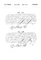
- FIG. 1is a schematic, pictorial illustration showing apparatus for cleaning a windshield of an automobile with heated washing fluid, in accordance with a preferred embodiment of the present invention
- FIG. 2is a schematic diagram showing details of the cleaning apparatus of FIG. 1, in accordance with a preferred embodiment of the present invention
- FIG. 3is a simplified pictorial illustration of a filling and drainage pumping system useful in the window de-icing and cleaning apparatus of FIG. 2, constructed and operative in accordance with a preferred embodiment of the present invention
- FIG. 4is a simplified pictorial illustration of a filling and drainage pumping system useful in the window de-icing and cleaning apparatus of FIG. 2, constructed and operative in accordance with another preferred embodiment of the present invention
- FIG. 5is a timing diagram illustrating operation of the apparatus of FIG. 1, in accordance with a preferred embodiment of the present invention
- FIG. 6is a simplified pictorial illustration of a multi-outlet spray head constructed and operative in accordance with a preferred embodiment of the present invention
- FIG. 7is a simplified pictorial illustration of a multi-outlet spray head constructed and operative in accordance with another preferred embodiment of the present invention.
- FIGS. 8 and 9are simplified pictorial illustrations of a windshield wiper actuator system constructed and operative in accordance with a preferred embodiment of the present invention, wherein FIG. 8 illustrates a summer parking mode and FIG. 9 illustrates a winter parking mode;
- FIG. 10is a simplified block diagram of the windshield wiper actuator system of FIGS. 8 and 9;
- FIGS. 11A-11Fare simplified illustrations of a typical operating sequence of the windshield wiper actuator system of FIGS. 8 and 9, in accordance with a preferred embodiment of the present invention.
- FIG. 12is a simplified illustration of a cam system for controlling a spray head during the operating sequence of the windshield wiper actuator system of FIGS. 11A-11F, in accordance with a preferred embodiment of the present invention
- FIGS. 13 and 14are simplified pictorial and sectional illustrations, respectively, of a windshield wiper constructed and operative in accordance with a preferred embodiment of the present invention, FIG. 14 being taken along lines XIV--XIV in FIG. 13;
- FIG. 15is a simplified, partially sectional illustration of a cartridge containing an additive which can be added to the fluid used in the windshield wiper cleaning apparatus of FIG. 1, constructed in accordance with a preferred embodiment of the present invention, wherein the cartridge is installed in the system and the additive flows into solution with the fluid;
- FIG. 16is a simplified pictorial illustration of the cartridge of FIG. 15;
- FIG. 17is a simplified pictorial illustration of a carrier for a plurality of such cartridges
- FIG. 18is a simplified, partially sectional illustration of a fluid authorization system for verifying use of an authorized fluid in the windshield wiper cleaning apparatus of FIG. 1, constructed in accordance with a preferred embodiment of the present invention.
- FIGS. 19A and 19Bare simplified, partially sectional illustrations of a solenoid constructed in accordance with a preferred embodiment of the present invention, and useful in the windshield wiper cleaning apparatus of the present invention, FIG. 19B taken along lines 19B--19B in FIG. 19A.
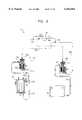
- FIG. 1is a schematic pictorial illustration showing electrically powered window de-icing and cleaning apparatus 20 for vehicles, in accordance with a preferred embodiment of the present invention, shown assembled for use in an automobile 22 having a windshield 24 coated with ice 26.
- a heatable vessel 28 for windshield washing fluidis connected between a washing fluid reservoir 30 of automobile 22 and spray heads 32, which spray the fluid onto windshield 24 when actuated by an operator 25 of the automobile.
- the operatormay actuate the apparatus either from inside or outside automobile 22, such as by means of a remote control 90, as shown in FIG. 1 and described further hereinbelow.
- Vessel 28has an inlet port 34, which receives washer fluid from reservoir 30, and an outlet port 36 through which heated fluid is discharged to spray heads 32.
- the fluidis driven by a pump 40, which is generally already present in automobile 22 for spraying unheated fluid to clean windshield 24.
- a battery 42provides power to apparatus 20, and wipers 44 clean melted ice and dirt from the windshield, as is known in the art.
- a controller 46regulates the operation of apparatus 20, and optionally also controls wipers 44 in conjunction with operation of the apparatus. Other aspects and details of the apparatus 20 are described further hereinbelow.
- FIG. 2shows details of vessel 28 and other elements of apparatus 20, in accordance with a preferred embodiment of the present invention.
- Vessel 28is generally cylindrical in shape and comprises an inner chamber 52 surrounded by an outer chamber 54.
- Inner chamber 52is contained and defined by an inner wall 56, preferably constructed of a metal such as stainless steel.
- Outer chamber 54is surrounded by an outer wall 58 of the vessel, preferably constructed of an insulating material, such as a plastic.
- a heating element 50 inside inner chamber 52heats the fluid in vessel 28.
- heat losses from vessel 28are minimized, since heat lost by the hot fluid in chamber 52 is used largely to pre-heat the colder fluid in chamber 54. Since the fluid in chamber 54 is cooler, its heat losses through outer wall 58 are relatively small.
- Heating element 50preferably comprises a resistively-heated electrical element, which is powered by battery 42 via controller 46, in accordance with a heating sequence described further hereinbelow.
- element 50may be heated by exchange of heat with a heat source in automobile 22, such as the engine cooling fluid or exhaust. Electrical heating by battery 42 is advantageous, however, since it allows vessel 28 to be heated rapidly even before the automobile is started.
- element 50draws approximately 400 W, which typical automobile batteries can supply easily.
- vessel 28is preferably sized so that within about one minute or less of actuation, it is capable of heating and discharging fluid of a volume and temperature sufficient to melt ice 26.
- inner chamber 52preferably contains about 50 ml of the fluid.
- the principles of the present inventionmay similarly be applied by scaling the volume of vessel 28 and the power of element 50 to any required capacity.
- the volume and power draw of the vesselwill typically be substantially larger than in automobile 22.
- pump 40 and inlet valve 66are operated to refill vessel 28.
- heating element 50 and wall 56are no longer as hot as they were before the initial quantity of the fluid was introduced into the vessel, they still retain some residual heat, facilitating rapid heating of the refilled fluid.
- the refilled fluidreaches a desired temperature, preferably with heating element 50 reaching a temperature of several hundred ° C., and/or after a predetermined period of time, it is discharged through spray heads 32.
- This processis repeated a desired number of times in sequence, until an entire sequence of discharges has been completed, as described hereinbelow, or until the windshield has been cleaned and/or de-iced, or until the temperature in vessel 28 drops below a predetermined minimum, or until it is interrupted by operator 25.
- the drivermay then again actuate apparatus 20 and begin a new cycle of heating and fluid discharge.
- each time vessel 28 is refilled, heated fluidis discharged through the spray heads 32 for about 3 sec, at intervals of about 5 sec or longer between fills, generally as determined by the time needed for the fluid to reach a desired temperature, such as 80-100° C.
- the temperature of later discharges in the sequencemay be less than that of the initial and other earlier discharges.
- wipers 44are operated in cooperation with the discharge of fluid from apparatus 20, so that the wipers 44 go on only during and shortly after the fluid discharge.
- wiper operationmay be delayed, so that the wipers do not operate during the initial discharge, when ice 26 has not yet melted, but only start from the second and subsequent discharges.
- valve 66is closed (relative to vessel 28), and drain valve 62 is preferably opened, so that any fluid remaining in the vessel can drain back into reservoir 30.
- Pump 40is generally not sealed against back-flow. Accordingly a pressure relief valve 73 is preferably provided to relieve any fluid pressure build-up in such a case. Pressure relief valve 73 allows the fluid to flow back to reservoir 30 in the event of over-pressure.
- An upper end 61 of drain port 60is preferably elevated relative to the bottom of chamber 52, so that a minimal amount of fluid will be left in vessel 28 even after draining. The vessel is then ready for rapid operation the next time apparatus 20 is actuated.
- Bypass line 76allows unheated fluid from reservoir 30 to be pumped directly to spray heads 32, without passing through vessel 28.
- Line 76is open to spray heads 32 whenever a valve 74, preferably a three-way valve, is closed relative to outlet port 36.
- Line 76can be used in warm weather, when de-icing is not needed, or when a cleaning spray is needed immediately, and there is not time to heat the fluid.
- Valve 74preferably remains open relative to line 76, so that fluid from the line is conveyed to spray heads 32, whenever the heating apparatus is not actuated.
- a one-way valve 80 in line 76preferably blocks any back-flow of fluid through the line.
- Apparatus 20thus provides additional window-cleaning functionality for automobile 22, at relatively low cost and without interfering with pre-existing window washing capabilities.
- the apparatusmay either be installed as part of the window washing system in a new automobile, or it may easily be retrofitted into an existing washing system.
- FIGS. 1 and 2the parts of apparatus 20 are shown in FIGS. 1 and 2 as being in certain positions and orientations relative to automobile 22 and the washing system therein, other positions and orientations are clearly possible.
- vessel 28may be placed at a different angle from the orientation shown in the figures, as long as ports 34, 36 and 60 are suitably positioned and oriented in the vessel.
- Controller 46Control of apparatus 20 by controller 46 is described hereinabove as being based on feedback to the controller provided by a sensor 64.
- This sensoris shown in FIG. 2 as being placed at the upper end of vessel 28, where it will measure the temperature either of vapor or fluid in chamber 52, depending on whether the chamber is empty or filled.
- Controller 46preferably tracks and monitors changes in temperature sensed by sensor 64 during heat/fill/discharge cycles of vessel 28. If the temperature exceeds a predetermined maximum, or if temperature changes do not follow a predetermined normal profile, the controller will conclude that a malfunction has occurred, such as blockage of inlet 34 or outlet 36 or a failure of sensor 64, and will preferably interrupt operation of the apparatus and notify operator 25 by an appropriate signal.
- a temperature sensor 301nearer the bottom of vessel 28, to measure the fluid temperature thereat, or a temperature sensor 302 mounted in, on or near heating element 50.
- Other sensorssuch as a pressure sensor or pressure-stat or a fluid level sensor 303, may also be fixed in the vessel and provide feedback to controller 46.
- Further temperature sensorsmay also be used, including a sensor 82 on an outer surface of vessel 28, a sensor 84 in reservoir 30 for measuring the temperature of fluid therein, and a sensor 86 on an outer surface of automobile 22, most preferably on windshield 24. These sensors provide inputs to controller 46, which accordingly sets parameters such as the voltage applied to element 50 and/or the lengths of time for which the element and fluid in vessel 28 are heated.
- the controllersets the parameters so that the fluid is sprayed onto windshield 24 at a temperature high enough to melt ice 26 quickly under prevalent ambient conditions, as indicated by sensor 86, for example, but not so high (relative to the temperature of the windshield) as to create a danger of cracking the windshield or violating safety regulations in this regard.
- the selection of the parametersis preferably automatic, without requiring intervention by operator 25 of automobile 22, except to actuate or de-actuate apparatus 20 as desired.
- a temperature sensor 304is preferably mounted on or near each spray head 32. Temperature sensor 304 may additionally be mounted at a tee-connection 305 of the spray heads. Temperatures of the spray heads 32 are input to controller 46 and provide further feedback control for setting parameters such as the voltage applied to element 50 and/or the lengths of time for which the element and fluid in vessel 28 are heated.
- heating element 50may not be submerged in the fluid, but rather may be exposed for most of its length to air inside vessel 28. In such a case, energizing heating element 50 may be wasteful, and worse, could cause damage from overheating.
- an auxiliary heating element 306is preferably disposed at the bottom of vessel 28. Heating element 306 may be shaped as a coil heater, for example, or any other suitable low-profile shape.
- Heating element 306is preferably connected to and controlled by controller 46, as is now described. If the amount of fluid in vessel 28 is sufficient to cover heating element 306 but not the majority of heating element 50, then it will take heating element 306 a relatively short time to heat fluid to a predetermined temperature, such as the boiling point. If, however, the amount of fluid in vessel 28 is sufficient to cover both heating elements 50 and 306, then it will take heating element 306 a longer time to heat fluid to the predetermined temperature. Temperature sensors 301 and 302, as well as fluid level sensors 303 and 309 or any other optional sensors mounted in vessel 28, may be used to monitor the time needed for the predetermined temperature rise, which time is processed by controller 46 to control heating of heating elements 50 and 306.
- controller 46interprets this to mean that the fluid covers only heating element 306, and thus only heating element 306 is energized and not heating element 50. If the time equals or exceeds the predetermined threshold, controller 46 interprets this to mean that the fluid sufficiently covers both heating elements 50 and 306, and thus both heating elements 50 and 306 are energized.
- thermoswitch 308may be provided at the upper end of vessel 28, which monitors the temperature either of vapor or fluid in chamber 52, depending on whether the chamber is empty or filled. If the temperature exceeds a predetermined maximum, thermoswitch 308 independently shuts down operation of the apparatus, even in the event of a failure in the electrical system of the vehicle or apparatus 20, and optionally, may notify operator 25 by an appropriate signal.
- FIG. 3illustrates a filling and drainage pumping system 310 useful in window de-icing and cleaning apparatus 20, constructed and operative in accordance with a preferred embodiment of the present invention.
- system 310preferably employs pump 40 described hereinabove.
- Pump 40is preferably a centrifugal water pump which means it is an irreversible pump, i.e., fluid flows generally from an inlet 40A to an outlet 40B.
- a first solenoid 312is in fluid communication between inlet 40A of pump 40 and reservoir 30.
- An interface port 314 of solenoid 312is preferably connected to reservoir 30 via a fluid line 324 and an outlet port 315 is preferably connected to inlet 40A via a fluid line 326 and a tee-connector 316.
- a second solenoid 318is preferably in fluid communication between outlet 40B of pump 40 and vessel 28.
- An interface port 320 of solenoid 318is preferably connected to inlet port 34 via a fluid line 328 and a tee-connector 330.
- Another port 319 of solenoid 318is preferably connected to outlet 40B via a tee-connector 322 and a fluid line 327.
- solenoids 312 and 318are preferably accomplished by means of controller 46.
- solenoids 312 and 318may be constructed as shown and described hereinbelow with reference to FIGS. 19A and 19B.
- Pumping system 310is used to fill vessel 28 when the solenoids are preferably in the normally open position.
- Pump 40is operated to draw fluid from reservoir 30 through fluid line 324 (in the direction of the solid line in FIG. 3) to solenoid 312.
- the fluidenters port 314 and flows out open port 315 through fluid line 326, past tee-connector 316 to inlet 40A of pump 40. It is noted that fluid does not flow from tee-connector 316 to solenoid 318 because port 336 is closed.
- the fluidflows from outlet 40B of pump 40 past tee-connector 322 via fluid line 327 to open port 319 of solenoid 318. Flow exits solenoid 318 via port 320 and fluid line 328 (in the direction of the solid line in FIG. 3) to tee-connector 330.
- Vessel 28is preferably equipped with a one-way valve 334 which permits fluid flow only out of drain port 60. Therefore, the fluid can only flow from tee-connector 330 to inlet port 34 which preferably comprises a valve (herein also referred to as a valve 34). Valve 34 is opened by controller 46, and the fluid fills vessel 28.
- valve 34is closed by controller 46 so that the fluid is forced to flow in fluid line 328 (in the direction of the dashed line in FIG. 3) to port 320 of solenoid 318. Since port 319 is closed, fluid flows out of port 336 of solenoid 318 via a fluid line 338 to tee-connector 316 (in the direction of the dashed line in FIG. 3).
- FIG. 4illustrates a filling and drainage pumping system 350 useful in window de-icing and cleaning apparatus 20, constructed and operative in accordance with another preferred embodiment of the present invention.
- Pumping system 350is similarly constructed to pumping system 310, with like elements being designated by like numerals. (Pressure relief valve 73 and other elements are not shown for the sake of simplicity.)
- Pumping system 350differs from system 310 in that system 350 preferably employs a reversible pump 352, such as a geared pump, i.e., fluid can flow both in and out of an first port 352A and a second port 352B.
- a reversible pump 352such as a geared pump
- pump 352When it is desired to fill vessel 28 with fluid, pump 352 is operated so that the fluid is pumped in the direction of arrows 356.
- the fluidflows from reservoir 30 via fluid line 324 through pump 352, thence via fluid line 328 to tee-connector 330, finally entering and filling vessel 28 via open valve 34, since the fluid cannot flow past one-way valve 334.
- pump 352When it is desired to drain fluid from vessel 28, the pumping direction of pump 352 is reversed so that pump 352 now pumps fluid in the direction of arrows 354. Fluid is drained out of drain port 60 and flows via one-way valve 334 to tee-connector 330. Valve 34 is closed so that the fluid is forced to flow in fluid line 328 back to pump 352, thence to reservoir 30, and the drainage is complete.
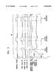
- FIG. 5is a timing diagram illustrating a sequence 96 of heat/fill/discharge cycles of apparatus 20, in accordance with a preferred embodiment of the present invention.
- the pumping system usedmay be the reversible pumping system of FIG. 4. In such a case, the pumping system may pump fluid towards vessel 28 (indicated by a positive ordinate in the graph) or it may drain fluid from vessel 28 (indicated by a negative ordinate in the graph). It is noted that pump 352 may be actuated intermittently when needed, or alternatively, pump 352 may be actuated continuously and controller 46 may be used to switch pump 352 between filling mode or draining mode as desired.
- drain valve 62is opened and heating element 306 and/or heating element 50 are energized to pre-heat vessel 28.
- Valve 62is closed, preferably after about 15 sec.
- the drain valvemay be held closed for a short period, preferably about 20 sec, so that the fluid in vessel 28 is heated to a high temperature before the valve is opened.
- controller 46determines that one of the valves, particularly inlet valve 66, is stuck and will not open, in which case the heated fluid is used to force the valve open.
- Heatingcontinues until sensors 64 or 301 reaches a target temperature, preferably about 85° C. (dependent on the exact position of the sensor), in chamber 52, or for about 70 sec, if the temperature does not reach the target temperature.
- pump 40 and inlet and outlet valves 66 and 74open, to admit and discharge the initial quantity of fluid.
- the temperature in chamber 52drops, and is subsequently reheated, preferably to about 60° C., whereupon a second quantity of the fluid is admitted and discharged.
- the process of reheating, fill and dischargecontinues for a predetermined number of cycles, or until terminated by operator 25.
- heating elements 50 and/or 306which are energized substantially continuously throughout the sequence, remain energized for about 15 sec more, in order to heat and drive out of vessel 28 as much as possible of any fluid remaining therein, down to the level of upper end 61.
- the apparatusis then ready to begin the next sequence, when required by the user.
- heating element 306is first energized before heating element 50, there preferably being a delay of about 2-10 sec before energization of heating element 50.
- heating element 50is turned off at the end of the cycle before heating element 306.
- the delays at the beginning and end of the cycles between heating elements 50 and 306are preferably part of the working cycle so as to prevent overheating of heating element 50 and to ensure proper initial heating of the quantity of fluid left in the bottom of vessel 28.
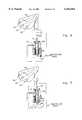
- Multi-outlet spray head 360preferably includes a plurality of outlets, such as a central outlet 362 and two outer outlets 364 and 366, although any number of outlets may also be employed.
- the outletsare fed fluid preferably via a solenoid 368.
- Solenoid 368has an inlet 382 into which fluid can flow from a pressurized fluid source.
- the fluidpreferably exits solenoid 368 from an outlet 372 via a tee-connector 374 to spray head outlets 364 and 366.
- Fluidis preferably fed directly from the pressurized fluid source via a tee-connection to central outlet 362.
- the flow of fluid from spray head 360can be controlled, such as by means of controller 46, to spray out of the outlets in a variety of manners.
- controller 46can energize solenoid 368 to a closed position such that the fluid initially exits central outlet 362 only, with no fluid initially exiting outlets 364 and 366.
- solenoid 368can be opened so that the fluid exits outlets 364 and 366, the fluid exiting these two outlets substantially simultaneously.
- Controller 46can then continue spraying from outlet 362, as well as outlets 364 and 366, or can cause any kind of combination of intermittent and continuous spraying from the three outlets. It is noted that in the embodiment of FIG. 6, outlets 364 and 366 always spray together.
- FIG. 7illustrates a multi-outlet spray head 360 constructed and operative in accordance with another preferred embodiment of the present invention, in which there is no tee-connector 374.
- Port 372feeds spray head outlet 364 and third port 378 feeds spray head outlet 366.
- the flow of fluid from spray head 360can be controlled, such as by means of controller 46, to spray out of the outlets in a variety of manners.
- controller 46can close solenoid 368 such that the fluid initially exits central outlet 362 and outlet 366, with no fluid exiting outlet 364.
- solenoid 368can be opened so that the fluid exits central outlet 362 and outlet 364, with no fluid exiting outlet 366.
- solenoid 368in a partially open position wherein fluid can exit both outlets 364 and 366, as well as central outlet 362.
- FIGS. 6 and 7The difference between the embodiments shown in FIGS. 6 and 7 is that in the embodiment of FIG. 6, outlets 364 and 366 always spray together, whereas in the embodiment of FIG. 7, outlets 364 and 366 spray independently of each other. It is thus appreciated that in general a greater variety of spray patterns are possible with the embodiment of FIG. 7 than with the embodiment of FIG. 6.
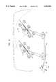
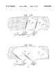
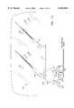
- FIGS. 8 and 9illustrate a windshield wiper actuator system 400 constructed and operative in accordance with a preferred embodiment of the present invention.
- Windshield wiper actuator system 400is capable of placing windshield wipers 402 and 404 in either summer parking mode (FIG. 8) or winter parking mode (FIG. 9).
- Windshield wiper actuator system 400preferably includes a motor 406 which is connected to the wipers by means of a bar 408 which is pivotally attached to a linkage arm 410 which is in turn pivotally connected by means of linkage members 412 and 414 to wipers 402 and 404, respectively.
- the limits of travel of linkage members 412 and 414are shown in phantom lines in FIGS. 8 and 9. It is seen that preferably sensors are provided for sensing the limits of the travel. For example, in the illustrated embodiment, a pair of microswitches 416 and 418 are provided. In the summer parking mode, the wipers 402 and 404 are brought to a horizontal or near horizontal position and a contact 420 of motor 406 actuates microswitch 416.
- the wipers 402 and 404are brought to a non-horizontal position, possibly even a vertical position, and contact 420 actuates microswitch 418. It is appreciated that other sensors may be used instead of microswitches, such as Hall effect sensors, to sense the limits of travel.
- the wipersIn the summer parking mode the wipers are at rest in a horizontal or near horizontal position, since in the summer there is generally no ice. However, in the winter, if there is a build-up of ice, the wipers may become stuck to the windshield, or even if not, the build-up of ice may prevent movement of the wipers. If the wipers were to be initially in a horizontal position, at the beginning of de-icing the wipers would start to move only at the bottom portion of the windshield, and the initially cleared area of the windshield would still not provide a convenient viewing area for safe driving.
- the driverwould have to wait until the de-icing apparatus had melted a sufficient amount of ice for the wipers to be able to swing up to clear a visible swath on the windshield for safe driving.
- the initially cleared area of the windshield, at the beginning of the de-icing processalready provides a convenient viewing area for safe driving.
- washer fluid(reference numeral 407) is discharged from wipers 402 and 404 themselves, such an embodiment being shown and described hereinbelow with reference to FIGS. 13 and 14.
- FIG. 10illustrates a simplified block diagram of windshield wiper actuator system 400.
- Motor 406is preferably controlled by a wiper controller 422 which preferably drives motor 406 via a power driver 424.
- Microswitches 416 and 418are preferably in electrical communication with controller 422.
- Temperature sensors 64 or 304are preferably in electrical communication with controller 422 as well.
- a shaft encoder 426is preferably provided that can sense the rotation of motor 406 and thus the rotation of the wipers as well. Shaft encoder 426 can also counts the number of pulses of motor 406 during operation of the wipers, the importance of which will be described further hereinbelow.
- controller 46can correlate the wind speed in terms of thermal effect on the fluid temperature and compensate therefor by heating the fluid to a higher temperature before spraying on the windshield. Alternatively, if there is no appreciable wind, controller 46 can save electricity and heat the fluid to a slightly lower temperature.
- the drivercan bring windshield wiper actuator system 400 into winter parking mode manually.
- system 400may be automatically actuated.
- temperature sensors 64 or 304, or a temperature sensor on the outside of the vehiclemay be used to sense a drop in temperature during the night, and the sensed change in temperature is interpreted by controller 422 to bring the windshield wipers to winter parking mode.
- motor 406is called upon to produce a large amount of torque and may become overheated or damaged. Therefore, it is important to prevent such damage to motor 406. This can be accomplished in several ways. For example, shaft encoder 426 or the commutation of motor 406 can be used to count the number of pulses of motor 406 during operation of the wipers. Controller 422 can compare the number of pulses with a predetermined amount to interpret whether or not motor 406 is being overworked. If motor 406 is being overworked, then controller 422 can shut down operation of motor 406 to prevent damage thereto.
- microswitches 416 and 418provides controllers 46 and 422 with an indication of the clockwise or counterclockwise movement of wipers 402 and 404.
- controllers 46 and 422can tell the direction of the wiper movement. Even for small movements of the wipers, wherein only one microswitch may be actuated, controllers 46 and 422 can still sense the direction of movement of the wipers.
- the number of times the particular microswitch is actuated, or alternatively, the number of pulses of motor 406can indicate the movement of the wipers.
- FIGS. 11A-11Fillustrate a typical operating sequence of windshield wiper actuator system 400 in accordance with a preferred embodiment of the present invention.
- the fluidis sprayed from spray head 360 (FIG. 7), but it is appreciated that other spray heads could also be used.
- wipers 402 and 404are in the winter parking mode and as such are positioned at some non-horizontal position.
- Central outlet 362 and outlet 364 of spray head 360spray fluid at zones 430 and 432 in order to start melting ice accumulated on the windshield.
- Motor 406tries to swing the wipers in a clockwise direction indicated by an arrow 434. The torque of motor 406 is measured for a predetermined period of time, such as 0.5 sec. If the torque reaches some predetermined value, controller 422 shuts down motor 406.
- central outlet 362 and outlet 364 of spray head 360continue to spray fluid at zones 430 and 432.
- Motor 406tries to swing the wipers in a counterclockwise direction indicated by an arrow 436. The torque of motor 406 is again measured for a predetermined period of time, and if the torque reaches some predetermined value, controller 422 shuts down motor 406.
- central outlet 362 and outlet 364 of spray head 360continue to spray fluid at zones 430 and 432.
- the fluidhas succeeded in melting some of the ice.
- Motor 406now succeeds in swinging the wipers both in clockwise and counterclockwise directions (arrows 434 and 436).
- controller 422switches the swing direction of the wipers from clockwise to counterclockwise and vice versa.
- outlet 366starts to spray fluid at a zone 438, and outlet 364 is temporarily shut down.
- Central outlet 362continues to spray fluid.
- Motor 406now tries to swing the wipers in the counterclockwise direction so as to start cleaning a further swath on the windshield.
- outlet 364may remain open to continue spraying fluid on the windshield.
- spray patternsmay be employed in cleaning and de-icing the windshield and the abovementioned pattern is just one of these possibilities.
- FIG. 11Ethe swath of the wipers has increased and more of the windshield is clean.
- FIG. 11Fthe fluid has succeeded in melting the ice and the wipers swing freely across the windshield.
- Spray head 360is preferably controlled by controller 46, as mentioned above.
- the control of the spray headsmay be accomplished in any suitable manner, electronically or mechanically, for example. An example of a novel way of controlling the spray heads is now described.
- FIG. 12illustrates a cam system 440 for controlling spray head 360 during the operating sequence of windshield wiper actuator system 400, in accordance with a preferred embodiment of the present invention.
- outlets 362, 364 and 366are preferably regulated by individual valves 442, 444 and 446, respectively.
- the valvesmay be electronic valves or solenoids, for example.
- the valvesare equipped with push rods 448, 450 and 452, respectively, which are actuated by a cam 454 attached to the wiper 402 or 404.
- cam 454is designed in accordance with a desired spray pattern. For example, as shown in FIG. 12, cam 454 may initially push down on rods 448 and 450 to actuate valves 442 and 444 to allow spraying from outlets 362 and 364, while initially rod 452 is not pushed down by cam 454 and thus outlet 366 is initially closed. As wiper 402 or 404 swings in the counterclockwise direction, cam 454 pushes down on rod 452 and opens outlet 366 for spraying therethrough, all the while outlets 362 and 364 remaining open. It is appreciated that a variety of spray patterns may be employed in cleaning and de-icing the windshield and the abovementioned pattern is just one of these possibilities.
- Windshield wiper 460preferably has a longitudinal bore 462 formed therethrough for flow of fluid therethrough. Bore 462 fluidly communicates with a plurality of outlet holes 464 for applying the fluid on a windshield.
- a blade 466extends from a body 468 of wiper 460 for cleaning the windshield. Fluid preferably enters bore 462 at one end 470 of wiper 460, an opposite end 472 being substantially sealed.
- FIGS. 15 and 16illustrate a cartridge 480 useful in the windshield wiper cleaning apparatus of the present invention, such as that of FIG. 1, constructed in accordance with a preferred embodiment of the present invention.
- the fluid used in the windshield wiper cleaning apparatus of the present inventionis any kind of suitable windshield washer fluid, and as such may contain an additive such as anti-freeze, for example.
- Cartridge 480is a convenient device for adding such an additive to the windshield washer fluid.
- cartridge 480contains an additive 482.
- Cartridge 480may be made of any kind of suitable material, such as plastic or metal, and additive 482 may be in liquid or solid form. In the case of solid form, cartridge 480 may itself be a solid block of additive.
- Cartridge 480fits into an apertured holder 484 which is sealed by a plug 486.
- Plug 486preferably sealingly snap fits into apertured holder 484 and is provided with a threaded neck 488.
- Below threaded neck 488is a neck portion 485 formed with a plurality of through holes 487. Holes 487 are in fluid communication with a bore 483 which is in turn in fluid communication with apertured holder 484.
- threaded neck 488can be screwed into a container 490 and is preferably sealed by an O-ring 491.
- Container 490has a fluid inlet 492 and a fluid outlet 494. Fluid may enter inlet 492, such as from reservoir 30 (FIG. 2) and flow through holes 487 and bore 483 into apertured holder 484.
- Cartridge 480becomes submerged in the fluid and additive 482 is mixed with the fluid, such as by seeping, leaching, or dissolving, for example. The fluid with the additive 482 then exits via outlet 494 and flows into vessel 28.
- a carrier 496may be provided for convenient storage of a plurality of cartridges 480.
- Fluid authorization system 500preferably includes a membrane 502 and a viewing window 504 both of which are preferably sealed by a seal 506, such as an O-ring, round or rectangular in shape, for example.
- Membrane 502is preferably constructed of a material that disintegrates if it is not in the presence of a fluid authorized for use with the windshield wiper cleaning apparatus of the present invention.
- additive 482 mixed with watermay cause a chemical reaction which inhibits decomposition or disintegration of membrane 502.
- any disintegration of membrane 502may be viewed through viewing window 504.
- FIGS. 19A and 19Billustrate a solenoid 510 constructed in accordance with a preferred embodiment of the present invention, and useful in the windshield wiper cleaning apparatus of the present invention.
- Solenoid 510preferably comprises a central shaft 512 at a distal end of which is secured a generally inverted U-shaped yoke 514.
- Electromagnetic apparatus 511is provided for moving shaft 512 generally linearly.
- a rod 516is preferably fixedly pinned to yoke 514 by a pin 518.
- Attached to a bottom portion of a body 520 of solenoid 510is a tube receiving member 522.
- Tube receiving member 522also preferably includes a pair of fixed rods 532 and 534 which pass through openings 536 and 538, respectively, formed in yoke 514.
- a tube 528is positioned between rod 516 of yoke 514 and fixed rod 532.
- a tube 530is positioned between rod 516 of yoke 514 and fixed rod 534.
- Yoke 514is disposed in a cavity 540 of tube receiving member 522.
- Tubes 528 and 530are preferably made of a resilient material, such as rubber or neoprene. The resilient tubes springing back from the compressed state to the non-compressed state applies a force on shaft 512 and further aids in the generally linear travel of shaft 512, thereby realizing energy savings.
- FIG. 19Aillustrates a normally open position of solenoid 510.
- rod 516squeezes tube 530, thereby substantially sealing tube 530 from passage therethrough of a fluid.
- Tube 530(as well as tube 528) preferably have an elliptical cross section (or other suitable non-circular shape) to facilitate flattening thereof Synergistically, this shape also enables smaller distances of travel of central shaft 512 and larger forces applied by the solenoid to the tubes.
- tube 528In the normally open position, tube 528 is not squeezed, and fluid may pass therethrough.
- Solenoid 510can be energized to a closed position. In this position, rod 516 is brought upwards in the sense of FIGS. 19A and 19B, and now squeezes tube 528, thereby substantially sealing tube 528 from passage therethrough of a fluid. In the closed position, tube 530 is not squeezed, and fluid may pass therethrough. It is also possible to energize solenoid 510 to be in a partially open position wherein fluid can exit both tubes 528 and 530.
- solenoid 510may be suitably modified to seal and open just one tube or more than two tubes, if desired. It is also appreciated that the normally open position and closed positions may be reversed. In addition, the tubes can be connected by suitable connections, such as tee-connections.
Landscapes
- Engineering & Computer Science (AREA)
- Mechanical Engineering (AREA)
- Water Supply & Treatment (AREA)
- Cleaning By Liquid Or Steam (AREA)
- Vehicle Cleaning, Maintenance, Repair, Refitting, And Outriggers (AREA)
- Window Of Vehicle (AREA)
- Nozzles (AREA)
- Spray Control Apparatus (AREA)
- Coating Apparatus (AREA)
Abstract
Description
Claims (17)
Priority Applications (14)
| Application Number | Priority Date | Filing Date | Title |
|---|---|---|---|
| US09/187,654US6164564A (en) | 1998-11-06 | 1998-11-06 | Apparatus for cleaning or de-icing a vehicle window |
| CNB998139912ACN1143736C (en) | 1998-11-06 | 1999-11-02 | Method and device for cleaning a window of a motor vehicle |
| CA002350040ACA2350040C (en) | 1998-11-06 | 1999-11-02 | Apparatus for cleaning or de-icing a vehicle window |
| JP2000580757AJP2003520151A (en) | 1998-11-06 | 1999-11-02 | Vehicle window cleaning or deicing equipment |
| PCT/US1999/025778WO2000027540A1 (en) | 1998-11-06 | 1999-11-02 | Apparatus for cleaning or de-icing a vehicle window |
| AU13383/00AAU1338300A (en) | 1998-11-06 | 1999-11-02 | Apparatus for cleaning or de-icing a vehicle window |
| HK02104816.2AHK1043074A1 (en) | 1998-11-06 | 1999-11-02 | Apparatus for cleaning or de-icing a vehicle window |
| AT99956864TATE337099T1 (en) | 1998-11-06 | 1999-11-02 | DEVICE FOR CLEANING OR DEFROSTING A VEHICLE WINDOW |
| CNB2004100033571ACN1302952C (en) | 1998-11-06 | 1999-11-02 | Apparatus for cleaning or de-icing a vehicle window |
| EP99956864AEP1126919B1 (en) | 1998-11-06 | 1999-11-02 | Apparatus for cleaning or de-icing a vehicle window |
| KR1020017005753AKR100628959B1 (en) | 1998-11-06 | 1999-11-02 | Devices for cleaning or deicing vehicle windows |
| DE69932941TDE69932941D1 (en) | 1998-11-06 | 1999-11-02 | DEVICE FOR CLEANING OR DEVICING A VEHICLE WINDOW |
| US10/085,763US6669109B2 (en) | 1998-11-06 | 2002-02-28 | Apparatus for cleaning or de-icing a vehicle window |
| US10/700,141US20040112981A1 (en) | 1998-11-06 | 2003-11-03 | Apparatus for cleaning or de-icing a vehicle window |
Applications Claiming Priority (1)
| Application Number | Priority Date | Filing Date | Title |
|---|---|---|---|
| US09/187,654US6164564A (en) | 1998-11-06 | 1998-11-06 | Apparatus for cleaning or de-icing a vehicle window |
Related Child Applications (1)
| Application Number | Title | Priority Date | Filing Date |
|---|---|---|---|
| US65428200AContinuation-In-Part | 1998-11-06 | 2000-09-01 |
Publications (1)
| Publication Number | Publication Date |
|---|---|
| US6164564Atrue US6164564A (en) | 2000-12-26 |
Family
ID=22689897
Family Applications (1)
| Application Number | Title | Priority Date | Filing Date |
|---|---|---|---|
| US09/187,654Expired - LifetimeUS6164564A (en) | 1998-11-06 | 1998-11-06 | Apparatus for cleaning or de-icing a vehicle window |
Country Status (11)
| Country | Link |
|---|---|
| US (1) | US6164564A (en) |
| EP (1) | EP1126919B1 (en) |
| JP (1) | JP2003520151A (en) |
| KR (1) | KR100628959B1 (en) |
| CN (2) | CN1143736C (en) |
| AT (1) | ATE337099T1 (en) |
| AU (1) | AU1338300A (en) |
| CA (1) | CA2350040C (en) |
| DE (1) | DE69932941D1 (en) |
| HK (1) | HK1043074A1 (en) |
| WO (1) | WO2000027540A1 (en) |
Cited By (87)
| Publication number | Priority date | Publication date | Assignee | Title |
|---|---|---|---|---|
| WO2002092237A1 (en)* | 2001-05-14 | 2002-11-21 | Microheat Inc. | System and method for cleaning or de-icing a windshield |
| US20030141381A1 (en)* | 2002-01-29 | 2003-07-31 | Bissonnette Lee A | Fluid heater |
| WO2003093080A1 (en)* | 2002-04-18 | 2003-11-13 | Seeber Ag & Co. Kg | Heatable liquid container for a motor vehicle |
| US20030234031A1 (en)* | 2002-06-24 | 2003-12-25 | Ford Global Technologies, Inc. | Automotive washer system with temperature adaptive washer fluid heating and mixing |
| US6669109B2 (en) | 1998-11-06 | 2003-12-30 | Micro-Heat Inc | Apparatus for cleaning or de-icing a vehicle window |
| US20040045587A1 (en)* | 1997-06-24 | 2004-03-11 | Shlomi Franco | Windshield de-icing |
| US20040118939A1 (en)* | 2002-10-02 | 2004-06-24 | Nartron Corporation | Vehicle windshield cleaning system |
| US6782196B1 (en) | 2003-02-28 | 2004-08-24 | Valeo Electrical Systems, Inc. | Fluid heater with freeze protection |
| US6789744B2 (en) | 2002-01-29 | 2004-09-14 | Valeo Electrical Systems, Inc. | Fluid heater with a variable mass flow path |
| US6839509B2 (en) | 2003-02-28 | 2005-01-04 | Valeo Electrical Systems, Inc. | Fluid heater control apparatus and method with overtemperature protection |
| US20050001058A1 (en)* | 2002-10-02 | 2005-01-06 | Nartron Corporation | Vehicle windshield cleaning system |
| FR2856969A1 (en)* | 2003-07-01 | 2005-01-07 | Gilbert Depierreux | Windshield defrosting device for motor vehicle, has tank associated with vacuum pump and connected to two pipes using valve placed at level of spray ring to drain latter pipe |
| US6850699B2 (en) | 2003-02-28 | 2005-02-01 | Valeo Electrical Systems, Inc. | Fluid heater temperature control apparatus and method |
| US20050077377A1 (en)* | 2003-09-12 | 2005-04-14 | Courian Kenneth J. | Determining whether thermal fluid-ejection nozzle ejected fluid upon firing based on temperature and/or resistance |
| US6896199B2 (en) | 2002-05-31 | 2005-05-24 | Valeo Electrical Systems, Inc. | Washing apparatus for multiple vehicle surfaces |
| US20050274398A1 (en)* | 2004-06-14 | 2005-12-15 | Fonville Carl E | Windshield wiper de-icing |
| US20060124761A1 (en)* | 2003-09-03 | 2006-06-15 | Nartron Corporation | Vehicle windshield cleaning system |
| US20060220598A1 (en)* | 2005-03-30 | 2006-10-05 | Randy Argo | Remote activation of an automotive window washing system |
| US7127158B1 (en)* | 2005-07-12 | 2006-10-24 | Jen-Yen Yen | Water sprayer and heater assembly for windshield wiper |
| US7184190B2 (en) | 2002-09-20 | 2007-02-27 | Donnelly Corporation | Electro-optic reflective element assembly |
| US7190893B2 (en) | 2003-06-27 | 2007-03-13 | Valeo Electrical Systems, Inc. | Fluid heater with low porosity thermal mass |
| US20070084484A1 (en)* | 2005-10-17 | 2007-04-19 | Porter Eugene B | Selectively controllable heated wash system |
| US7255451B2 (en) | 2002-09-20 | 2007-08-14 | Donnelly Corporation | Electro-optic mirror cell |
| US7274501B2 (en) | 2002-09-20 | 2007-09-25 | Donnelly Corporation | Mirror reflective element assembly |
| US20070284457A1 (en)* | 2002-10-02 | 2007-12-13 | Nartron Corporation | Vehicle Windshield Cleaning System |
| US7310177B2 (en) | 2002-09-20 | 2007-12-18 | Donnelly Corporation | Electro-optic reflective element assembly |
| US20080142747A1 (en)* | 2006-12-18 | 2008-06-19 | Jennings Jeffrey D | Tube configured pressure regulating valve |
| US7400435B2 (en) | 2005-01-19 | 2008-07-15 | Donnelly Corporation | Mirror assembly with heater element |
| US20080277497A1 (en)* | 2002-10-02 | 2008-11-13 | Nartron Corporation | Vehicle Windshield Cleaning System |
| WO2007046106A3 (en)* | 2005-10-19 | 2009-04-09 | Microheat Inc | Vehicle surface cleaning ανd de-icing |
| US20090140068A1 (en)* | 2005-09-20 | 2009-06-04 | Marco Ranalli | Injection Nozzle Having Heating Element And Heat Accumulator And Method For Introducing An Oxidizable Fluid Into An Exhaust System Upstream Of A Catalytic Converter Or Filter |
| US20090151107A1 (en)* | 2002-10-02 | 2009-06-18 | Nartron Corporation | Vehicle windshield cleaning system |
| US20090235460A1 (en)* | 2006-09-18 | 2009-09-24 | Cascade Designs, Inc. | Composite cushion with compression modulated valve and valve assembly there for |
| US7626749B2 (en) | 2005-05-16 | 2009-12-01 | Donnelly Corporation | Vehicle mirror assembly with indicia at reflective element |
| US20100028219A1 (en)* | 2008-07-30 | 2010-02-04 | Ford Global Technologies, Llc | Freezable-liquid dispenser for motor vehicles |
| US7813023B2 (en) | 2008-06-09 | 2010-10-12 | Magna Mirrors Of America, Inc. | Electro-optic mirror |
| US7824045B2 (en) | 2007-05-23 | 2010-11-02 | Donnelly Corporation | Exterior mirror element with wide angle portion |
| US7905427B2 (en) | 2004-02-12 | 2011-03-15 | M-Heat Investors, Llc | Apparatus and method for cleaning and de-icing |
| US7918570B2 (en) | 2002-06-06 | 2011-04-05 | Donnelly Corporation | Vehicular interior rearview information mirror system |
| US7934843B2 (en) | 2003-05-20 | 2011-05-03 | Donnelly Corporation | Exterior sideview mirror system |
| US7994471B2 (en) | 1998-01-07 | 2011-08-09 | Donnelly Corporation | Interior rearview mirror system with forwardly-viewing camera |
| US8000894B2 (en) | 2000-03-02 | 2011-08-16 | Donnelly Corporation | Vehicular wireless communication system |
| US8019505B2 (en) | 2003-10-14 | 2011-09-13 | Donnelly Corporation | Vehicle information display |
| US8049640B2 (en) | 2003-05-19 | 2011-11-01 | Donnelly Corporation | Mirror assembly for vehicle |
| US8063753B2 (en) | 1997-08-25 | 2011-11-22 | Donnelly Corporation | Interior rearview mirror system |
| US8083386B2 (en) | 2001-01-23 | 2011-12-27 | Donnelly Corporation | Interior rearview mirror assembly with display device |
| US8094002B2 (en) | 1998-01-07 | 2012-01-10 | Donnelly Corporation | Interior rearview mirror system |
| US8100568B2 (en) | 1997-08-25 | 2012-01-24 | Donnelly Corporation | Interior rearview mirror system for a vehicle |
| US8102279B2 (en) | 2007-11-05 | 2012-01-24 | Magna Mirrors Of America, Inc. | Exterior mirror with indicator |
| US8106347B2 (en) | 2002-05-03 | 2012-01-31 | Donnelly Corporation | Vehicle rearview mirror system |
| US8162493B2 (en) | 1999-11-24 | 2012-04-24 | Donnelly Corporation | Interior rearview mirror assembly for vehicle |
| US8164817B2 (en) | 1994-05-05 | 2012-04-24 | Donnelly Corporation | Method of forming a mirrored bent cut glass shape for vehicular exterior rearview mirror assembly |
| US8179586B2 (en) | 2003-10-02 | 2012-05-15 | Donnelly Corporation | Rearview mirror assembly for vehicle |
| US8242896B2 (en) | 2006-10-24 | 2012-08-14 | Donnelly Corporation | Vehicle exterior rearview mirror system with a highly viewable display indicator for the driver |
| US8282226B2 (en) | 2002-06-06 | 2012-10-09 | Donnelly Corporation | Interior rearview mirror system |
| US8288711B2 (en) | 1998-01-07 | 2012-10-16 | Donnelly Corporation | Interior rearview mirror system with forwardly-viewing camera and a control |
| US8391695B2 (en) | 2006-07-24 | 2013-03-05 | M-Heat Investors, Llc | Vehicle surfaces cleaning and de-icing system and method |
| US8427288B2 (en) | 2000-03-02 | 2013-04-23 | Donnelly Corporation | Rear vision system for a vehicle |
| US8508383B2 (en) | 2008-03-31 | 2013-08-13 | Magna Mirrors of America, Inc | Interior rearview mirror system |
| US8511841B2 (en) | 1994-05-05 | 2013-08-20 | Donnelly Corporation | Vehicular blind spot indicator mirror |
| US8525703B2 (en) | 1998-04-08 | 2013-09-03 | Donnelly Corporation | Interior rearview mirror system |
| US8529108B2 (en) | 2002-09-20 | 2013-09-10 | Donnelly Corporation | Mirror assembly for vehicle |
| US8561917B2 (en) | 2002-10-21 | 2013-10-22 | M-Heat Investors, Llc | Apparatus and method for cleaning or de-icing vehicle elements |
| US8610992B2 (en) | 1997-08-25 | 2013-12-17 | Donnelly Corporation | Variable transmission window |
| US8653959B2 (en) | 2001-01-23 | 2014-02-18 | Donnelly Corporation | Video mirror system for a vehicle |
| US8736940B2 (en) | 2011-09-30 | 2014-05-27 | Magna Mirrors Of America, Inc. | Exterior mirror with integral spotter mirror and method of making same |
| US8801245B2 (en) | 2011-11-14 | 2014-08-12 | Magna Mirrors Of America, Inc. | Illumination module for vehicle |
| US8908039B2 (en) | 2000-03-02 | 2014-12-09 | Donnelly Corporation | Vehicular video mirror system |
| US8988755B2 (en) | 2011-05-13 | 2015-03-24 | Magna Mirrors Of America, Inc. | Mirror reflective element |
| US9019091B2 (en) | 1999-11-24 | 2015-04-28 | Donnelly Corporation | Interior rearview mirror system |
| US9205780B2 (en) | 2010-02-04 | 2015-12-08 | Magna Mirrors Of America, Inc. | Electro-optic rearview mirror assembly for vehicle |
| US9216691B2 (en) | 2013-02-25 | 2015-12-22 | Magna Mirrors Of America, Inc. | Exterior mirror with spotter mirror |
| US20160114767A1 (en)* | 2014-10-22 | 2016-04-28 | Umm Al-Qura University | Liquid dispensing apparatus |
| US9481304B2 (en) | 2010-05-24 | 2016-11-01 | Magna Mirrors Of America, Inc. | Automotive exterior mirror heater control |
| US9659498B2 (en) | 2015-09-28 | 2017-05-23 | Magna Mirrors Of America, Inc. | Exterior mirror assembly with blind zone indicator |
| US9761144B2 (en) | 2014-09-11 | 2017-09-12 | Magna Mirrors Of America, Inc. | Exterior mirror with blind zone indicator |
| US9776569B2 (en) | 2015-01-30 | 2017-10-03 | Magna Mirrors Of America, Inc. | Exterior mirror with heater pad |
| US9809171B2 (en) | 2000-03-02 | 2017-11-07 | Magna Electronics Inc. | Vision system for vehicle |
| US10384653B2 (en) | 2004-03-09 | 2019-08-20 | Uusi, Llc | Vehicle windshield cleaning system |
| US10392810B1 (en)* | 2016-06-22 | 2019-08-27 | James Demirkan | Universal lightweight and portable deicing mat |
| US11221240B2 (en) | 2018-04-30 | 2022-01-11 | Ford Global Technologies, Llc | Sensor housing drainage |
| US11242009B2 (en) | 2005-07-06 | 2022-02-08 | Donnelly Corporation | Vehicular exterior mirror system with blind spot indicator |
| US11332101B2 (en) | 2004-03-09 | 2022-05-17 | Uusi, Llc | Vehicle windshield cleaning system |
| US11498487B2 (en) | 2005-07-06 | 2022-11-15 | Magna Mirrors Of America, Inc. | Vehicular exterior mirror system with blind spot indicator |
| US20230304271A1 (en)* | 2020-07-31 | 2023-09-28 | I.V.A.R. S.P.A. | Apparatus and method for controlling the distribution of a fluid, with an anti-freeze safety function |
| US20230382351A1 (en)* | 2022-05-24 | 2023-11-30 | Scott Jason Matiyow | Vehicle Wiper & Washer Actuation System |
| US11890991B2 (en) | 2006-10-24 | 2024-02-06 | Magna Mirrors Of America, Inc. | Vehicular exterior rearview mirror assembly with blind spot indicator element |
Families Citing this family (23)
| Publication number | Priority date | Publication date | Assignee | Title |
|---|---|---|---|---|
| DE20021641U1 (en)* | 2000-12-20 | 2001-02-22 | Reitter & Schefenacker GmbH & Co. KG, 73730 Esslingen | Cleaning device for vehicles, preferably motor vehicles |
| CN100480110C (en)* | 2002-10-21 | 2009-04-22 | 微热公司 | Apparatus and method for cleaning or de-icing a vehicle element |
| US6952524B2 (en) | 2002-11-27 | 2005-10-04 | Valeo Electrical Systems, Inc. | Fluid heater temperature balancing apparatus |
| US6889005B2 (en) | 2003-04-04 | 2005-05-03 | Valeo Electrical Systems, Inc. | Fluid heater with compressible cover freeze protection |
| KR100704586B1 (en) | 2005-07-27 | 2007-04-06 | 현대자동차주식회사 | Washer liquid heater |
| JP4960650B2 (en)* | 2006-04-18 | 2012-06-27 | 日出幸 清水 | Automotive wind glass cleaning equipment |
| DE102006029406A1 (en)* | 2006-06-27 | 2008-01-03 | Behr-Hella Thermocontrol Gmbh | Turned off vehicle`s frontpanel partial area defrosting method, involves examining whether energy stored in battery is larger than given minimum value sufficient for starting vehicle before introducing heat energy |
| KR101063398B1 (en)* | 2009-12-01 | 2011-09-07 | 기아자동차주식회사 | Washer pump device with washer liquid heating function |
| CN102058346B (en)* | 2010-12-30 | 2013-06-05 | 北京联合大学 | Casement cleaning device |
| JP5536680B2 (en)* | 2011-01-13 | 2014-07-02 | 株式会社村上開明堂 | Washer liquid heating device |
| FR2976538B1 (en)* | 2011-06-17 | 2013-07-26 | Valeo Systemes Dessuyage | CONNECTOR SUPPORT AND DEVICE FOR DISPENSING WINDSCREEN WASHING LIQUID FOR MOTOR VEHICLE WIPER BLADES |
| KR101359272B1 (en)* | 2012-06-25 | 2014-02-06 | 경북대학교 산학협력단 | Frost removal device for automobile |
| KR101646006B1 (en) | 2015-01-08 | 2016-08-08 | 강귀동 | An Apparatus for Clearing with a Structure of Pressure Vessel |
| JP6282625B2 (en)* | 2015-10-22 | 2018-02-21 | 株式会社ミツバ | Control unit for washer device and mounting structure thereof |
| FR3060493B1 (en)* | 2016-12-19 | 2019-01-25 | Valeo Systemes D'essuyage | WIPING SYSTEM FOR A MOTOR VEHICLE |
| CA3050069C (en)* | 2017-01-30 | 2021-09-07 | Takao Kambe | Steam air wiper system |
| DE102017103158B4 (en)* | 2017-02-16 | 2022-04-07 | Kautex Textron Gmbh & Co. Kg | vehicle surface cleaning device |
| JP6568556B2 (en)* | 2017-07-20 | 2019-08-28 | 本田技研工業株式会社 | Washer liquid supply system |
| CN109703524A (en)* | 2017-10-26 | 2019-05-03 | 郑州宇通客车股份有限公司 | Vehicle and its lamp system, car light jet stream Wiping device |
| EP3922520A4 (en)* | 2019-02-04 | 2022-06-29 | Koito Manufacturing Co., Ltd. | Vehicle cleaner system |
| DE102019217841A1 (en)* | 2019-11-19 | 2021-05-20 | Robert Bosch Gmbh | Wiper device for a windshield wiper |
| CN112783054B (en)* | 2021-01-04 | 2022-03-08 | 海门市帕源路桥建设有限公司 | Electric remote control system |
| CN115042932A (en)* | 2022-05-26 | 2022-09-13 | 中船黄埔文冲船舶有限公司 | Metal window washing system with spray head and washing method thereof |
Citations (14)
| Publication number | Priority date | Publication date | Assignee | Title |
|---|---|---|---|---|
| US653629A (en)* | 1899-10-17 | 1900-07-10 | Levin H Burkhardt | Device for cutting off the flow of water through flexible pipes. |
| US3979068A (en)* | 1975-07-14 | 1976-09-07 | Lawrence Peska Associates, Inc. | Spray nozzle assembly for a windshield of an automobile |
| US4090668A (en)* | 1976-12-06 | 1978-05-23 | Kochenour Paul R | Windshield washer and deicer |
| US4106508A (en)* | 1976-08-31 | 1978-08-15 | Richard Barnard Berlin | Clamp device |
| US5012977A (en)* | 1989-09-18 | 1991-05-07 | General Motors Corporation | Vehicle window washer with washer fluid temperature responsive pressure control |
| US5118040A (en)* | 1990-05-15 | 1992-06-02 | Tadashi Abe | Apparatus for washing the window glass of a vehicle |
| US5254083A (en)* | 1992-02-10 | 1993-10-19 | Conmed Corporation | Suction and irrigation apparatus |
| US5354965A (en)* | 1990-08-21 | 1994-10-11 | Gensonic, Inc. | Window cleaning fluid heating system having timer-controlled heater and differential input circuit |
| US5383247A (en)* | 1991-04-12 | 1995-01-24 | Citadel Inventments Limited | Washing installation for windshields or motor vehicles, aircraft, locomotives or the like |
| US5509606A (en)* | 1993-10-04 | 1996-04-23 | Koltech, Inc. | Instant hot wash device |
| US5927608A (en)* | 1995-05-29 | 1999-07-27 | Cooper Automotive Products, Inc. | Washing liquid heating |
| US5947348A (en)* | 1997-10-07 | 1999-09-07 | Briski; Richard J. | Beverage tapper shut-off mechanism |
| US5957384A (en)* | 1997-08-26 | 1999-09-28 | Lansinger; Jere Rask | Windshield heated wiping system |
| US5988529A (en)* | 1996-09-19 | 1999-11-23 | Volkswagen Ag | Liquid spraying arrangement for windows |
Family Cites Families (13)
| Publication number | Priority date | Publication date | Assignee | Title |
|---|---|---|---|---|
| GB642201A (en)* | 1947-03-05 | 1950-08-30 | Trico Products Corp | Improvements in or relating to a windshield washing apparatus |
| AT313083B (en)* | 1971-05-18 | 1974-01-25 | Manfred Hochkofler | Windscreen washer |
| JPS5868363U (en)* | 1981-10-30 | 1983-05-10 | スタンレー電気株式会社 | Wiper-linked washer device |
| JPS6124257U (en)* | 1984-07-16 | 1986-02-13 | トヨタ自動車株式会社 | Vehicle wiper device |
| JPS6131955U (en)* | 1984-07-31 | 1986-02-26 | 自動車電機工業株式会社 | wiper device |
| JPS61224826A (en)* | 1985-03-28 | 1986-10-06 | 古河電気工業株式会社 | DC motor protection device |
| JPS63306953A (en)* | 1987-06-09 | 1988-12-14 | Nippon Denso Co Ltd | Hot water windshield washer for vehicle |
| JPH0274445A (en)* | 1988-09-09 | 1990-03-14 | Nippon Soken Inc | Washer device for vehicle |
| JPH02102854A (en)* | 1988-10-11 | 1990-04-16 | Nec Corp | Windshield wiper controller |
| JPH02286451A (en)* | 1989-04-27 | 1990-11-26 | Nec Corp | Windshield wiper controller |
| JPH07223510A (en)* | 1994-02-07 | 1995-08-22 | Araco Corp | Window washer |
| FI105887B (en) | 1996-09-27 | 2000-10-31 | Suomen Sokeri Oy | Products containing plant sterol and useful in food applications and therapeutic applications process for the preparation thereof and their use |
| US5784751A (en)* | 1997-03-04 | 1998-07-28 | Tippets; Clyde A. | Heat absorbing windshield wiper |
- 1998
- 1998-11-06USUS09/187,654patent/US6164564A/ennot_activeExpired - Lifetime
- 1999
- 1999-11-02EPEP99956864Apatent/EP1126919B1/ennot_activeExpired - Lifetime
- 1999-11-02HKHK02104816.2Apatent/HK1043074A1/enunknown
- 1999-11-02CACA002350040Apatent/CA2350040C/ennot_activeExpired - Fee Related
- 1999-11-02CNCNB998139912Apatent/CN1143736C/ennot_activeExpired - Fee Related
- 1999-11-02AUAU13383/00Apatent/AU1338300A/ennot_activeAbandoned
- 1999-11-02ATAT99956864Tpatent/ATE337099T1/ennot_activeIP Right Cessation
- 1999-11-02WOPCT/US1999/025778patent/WO2000027540A1/enactiveIP Right Grant
- 1999-11-02DEDE69932941Tpatent/DE69932941D1/ennot_activeExpired - Lifetime
- 1999-11-02JPJP2000580757Apatent/JP2003520151A/enactivePending
- 1999-11-02KRKR1020017005753Apatent/KR100628959B1/ennot_activeExpired - Fee Related
- 1999-11-02CNCNB2004100033571Apatent/CN1302952C/ennot_activeExpired - Fee Related
Patent Citations (14)
| Publication number | Priority date | Publication date | Assignee | Title |
|---|---|---|---|---|
| US653629A (en)* | 1899-10-17 | 1900-07-10 | Levin H Burkhardt | Device for cutting off the flow of water through flexible pipes. |
| US3979068A (en)* | 1975-07-14 | 1976-09-07 | Lawrence Peska Associates, Inc. | Spray nozzle assembly for a windshield of an automobile |
| US4106508A (en)* | 1976-08-31 | 1978-08-15 | Richard Barnard Berlin | Clamp device |
| US4090668A (en)* | 1976-12-06 | 1978-05-23 | Kochenour Paul R | Windshield washer and deicer |
| US5012977A (en)* | 1989-09-18 | 1991-05-07 | General Motors Corporation | Vehicle window washer with washer fluid temperature responsive pressure control |
| US5118040A (en)* | 1990-05-15 | 1992-06-02 | Tadashi Abe | Apparatus for washing the window glass of a vehicle |
| US5354965A (en)* | 1990-08-21 | 1994-10-11 | Gensonic, Inc. | Window cleaning fluid heating system having timer-controlled heater and differential input circuit |
| US5383247A (en)* | 1991-04-12 | 1995-01-24 | Citadel Inventments Limited | Washing installation for windshields or motor vehicles, aircraft, locomotives or the like |
| US5254083A (en)* | 1992-02-10 | 1993-10-19 | Conmed Corporation | Suction and irrigation apparatus |
| US5509606A (en)* | 1993-10-04 | 1996-04-23 | Koltech, Inc. | Instant hot wash device |
| US5927608A (en)* | 1995-05-29 | 1999-07-27 | Cooper Automotive Products, Inc. | Washing liquid heating |
| US5988529A (en)* | 1996-09-19 | 1999-11-23 | Volkswagen Ag | Liquid spraying arrangement for windows |
| US5957384A (en)* | 1997-08-26 | 1999-09-28 | Lansinger; Jere Rask | Windshield heated wiping system |
| US5947348A (en)* | 1997-10-07 | 1999-09-07 | Briski; Richard J. | Beverage tapper shut-off mechanism |
Cited By (297)
| Publication number | Priority date | Publication date | Assignee | Title |
|---|---|---|---|---|
| US8164817B2 (en) | 1994-05-05 | 2012-04-24 | Donnelly Corporation | Method of forming a mirrored bent cut glass shape for vehicular exterior rearview mirror assembly |
| US8511841B2 (en) | 1994-05-05 | 2013-08-20 | Donnelly Corporation | Vehicular blind spot indicator mirror |
| US8559093B2 (en) | 1995-04-27 | 2013-10-15 | Donnelly Corporation | Electrochromic mirror reflective element for vehicular rearview mirror assembly |
| US7445165B2 (en) | 1997-06-24 | 2008-11-04 | Micro-Heat, Inc. | Apparatus and method for windshield cleaning and de-icing |
| US20040045587A1 (en)* | 1997-06-24 | 2004-03-11 | Shlomi Franco | Windshield de-icing |
| US7171716B2 (en)* | 1997-06-24 | 2007-02-06 | Micro-Heat, Inc. | Windshield de-icing |
| US7775224B2 (en) | 1997-06-24 | 2010-08-17 | M-Heat Investors, Llc | Windshield de-icing |
| US20070094832A1 (en)* | 1997-06-24 | 2007-05-03 | Shlomi Franco | Windshield de-icing |
| US20050284503A1 (en)* | 1997-06-24 | 2005-12-29 | Micro-Heat, Inc. | Windshield de-icing |
| US20090014035A1 (en)* | 1997-06-24 | 2009-01-15 | Shlomi Franco | Windshield de-icing |
| US6892417B2 (en)* | 1997-06-24 | 2005-05-17 | Micro-Heat, Inc. | Windshield de-icing |
| US8100568B2 (en) | 1997-08-25 | 2012-01-24 | Donnelly Corporation | Interior rearview mirror system for a vehicle |
| US8063753B2 (en) | 1997-08-25 | 2011-11-22 | Donnelly Corporation | Interior rearview mirror system |
| US8267559B2 (en) | 1997-08-25 | 2012-09-18 | Donnelly Corporation | Interior rearview mirror assembly for a vehicle |
| US8610992B2 (en) | 1997-08-25 | 2013-12-17 | Donnelly Corporation | Variable transmission window |
| US8779910B2 (en) | 1997-08-25 | 2014-07-15 | Donnelly Corporation | Interior rearview mirror system |
| US7994471B2 (en) | 1998-01-07 | 2011-08-09 | Donnelly Corporation | Interior rearview mirror system with forwardly-viewing camera |
| US8325028B2 (en) | 1998-01-07 | 2012-12-04 | Donnelly Corporation | Interior rearview mirror system |
| US8134117B2 (en) | 1998-01-07 | 2012-03-13 | Donnelly Corporation | Vehicular having a camera, a rain sensor and a single-ball interior electrochromic mirror assembly attached at an attachment element |
| US8094002B2 (en) | 1998-01-07 | 2012-01-10 | Donnelly Corporation | Interior rearview mirror system |
| US8288711B2 (en) | 1998-01-07 | 2012-10-16 | Donnelly Corporation | Interior rearview mirror system with forwardly-viewing camera and a control |
| US9221399B2 (en) | 1998-04-08 | 2015-12-29 | Magna Mirrors Of America, Inc. | Automotive communication system |
| US8884788B2 (en) | 1998-04-08 | 2014-11-11 | Donnelly Corporation | Automotive communication system |
| US8525703B2 (en) | 1998-04-08 | 2013-09-03 | Donnelly Corporation | Interior rearview mirror system |
| US9481306B2 (en) | 1998-04-08 | 2016-11-01 | Donnelly Corporation | Automotive communication system |
| US20040112981A1 (en)* | 1998-11-06 | 2004-06-17 | Vyshislav Ivanov | Apparatus for cleaning or de-icing a vehicle window |
| US6669109B2 (en) | 1998-11-06 | 2003-12-30 | Micro-Heat Inc | Apparatus for cleaning or de-icing a vehicle window |
| US9019091B2 (en) | 1999-11-24 | 2015-04-28 | Donnelly Corporation | Interior rearview mirror system |
| US9278654B2 (en) | 1999-11-24 | 2016-03-08 | Donnelly Corporation | Interior rearview mirror system for vehicle |
| US8162493B2 (en) | 1999-11-24 | 2012-04-24 | Donnelly Corporation | Interior rearview mirror assembly for vehicle |
| US10144355B2 (en) | 1999-11-24 | 2018-12-04 | Donnelly Corporation | Interior rearview mirror system for vehicle |
| US9376061B2 (en) | 1999-11-24 | 2016-06-28 | Donnelly Corporation | Accessory system of a vehicle |
| US8908039B2 (en) | 2000-03-02 | 2014-12-09 | Donnelly Corporation | Vehicular video mirror system |
| US10131280B2 (en) | 2000-03-02 | 2018-11-20 | Donnelly Corporation | Vehicular video mirror system |
| US8427288B2 (en) | 2000-03-02 | 2013-04-23 | Donnelly Corporation | Rear vision system for a vehicle |
| US8543330B2 (en) | 2000-03-02 | 2013-09-24 | Donnelly Corporation | Driver assist system for vehicle |
| US8676491B2 (en) | 2000-03-02 | 2014-03-18 | Magna Electronics Inc. | Driver assist system for vehicle |
| US8271187B2 (en) | 2000-03-02 | 2012-09-18 | Donnelly Corporation | Vehicular video mirror system |
| US9783114B2 (en) | 2000-03-02 | 2017-10-10 | Donnelly Corporation | Vehicular video mirror system |
| US10239457B2 (en) | 2000-03-02 | 2019-03-26 | Magna Electronics Inc. | Vehicular vision system |
| US9315151B2 (en) | 2000-03-02 | 2016-04-19 | Magna Electronics Inc. | Driver assist system for vehicle |
| US10179545B2 (en) | 2000-03-02 | 2019-01-15 | Magna Electronics Inc. | Park-aid system for vehicle |
| US9809168B2 (en) | 2000-03-02 | 2017-11-07 | Magna Electronics Inc. | Driver assist system for vehicle |
| US9809171B2 (en) | 2000-03-02 | 2017-11-07 | Magna Electronics Inc. | Vision system for vehicle |
| US9014966B2 (en) | 2000-03-02 | 2015-04-21 | Magna Electronics Inc. | Driver assist system for vehicle |
| US10053013B2 (en) | 2000-03-02 | 2018-08-21 | Magna Electronics Inc. | Vision system for vehicle |
| US8000894B2 (en) | 2000-03-02 | 2011-08-16 | Donnelly Corporation | Vehicular wireless communication system |
| US8121787B2 (en) | 2000-03-02 | 2012-02-21 | Donnelly Corporation | Vehicular video mirror system |
| US9694749B2 (en) | 2001-01-23 | 2017-07-04 | Magna Electronics Inc. | Trailer hitching aid system for vehicle |
| US8653959B2 (en) | 2001-01-23 | 2014-02-18 | Donnelly Corporation | Video mirror system for a vehicle |
| US8083386B2 (en) | 2001-01-23 | 2011-12-27 | Donnelly Corporation | Interior rearview mirror assembly with display device |
| US8654433B2 (en) | 2001-01-23 | 2014-02-18 | Magna Mirrors Of America, Inc. | Rearview mirror assembly for vehicle |
| US10272839B2 (en) | 2001-01-23 | 2019-04-30 | Magna Electronics Inc. | Rear seat occupant monitoring system for vehicle |
| US9352623B2 (en) | 2001-01-23 | 2016-05-31 | Magna Electronics Inc. | Trailer hitching aid system for vehicle |
| CN100357139C (en)* | 2001-05-14 | 2007-12-26 | 米克罗希特公司 | Liquid heating for windshields |
| WO2002092237A1 (en)* | 2001-05-14 | 2002-11-21 | Microheat Inc. | System and method for cleaning or de-icing a windshield |
| AU2002302946B2 (en)* | 2001-05-14 | 2007-02-01 | Micro-Heat, Inc. | System and method for cleaning or de-icing a windshield |
| US20030141381A1 (en)* | 2002-01-29 | 2003-07-31 | Bissonnette Lee A | Fluid heater |
| US6789744B2 (en) | 2002-01-29 | 2004-09-14 | Valeo Electrical Systems, Inc. | Fluid heater with a variable mass flow path |
| US6912357B2 (en) | 2002-01-29 | 2005-06-28 | Valeo Electrical Systems, Inc. | Fluid heater |
| WO2003093080A1 (en)* | 2002-04-18 | 2003-11-13 | Seeber Ag & Co. Kg | Heatable liquid container for a motor vehicle |
| US8106347B2 (en) | 2002-05-03 | 2012-01-31 | Donnelly Corporation | Vehicle rearview mirror system |
| US8304711B2 (en) | 2002-05-03 | 2012-11-06 | Donnelly Corporation | Vehicle rearview mirror system |
| US6896199B2 (en) | 2002-05-31 | 2005-05-24 | Valeo Electrical Systems, Inc. | Washing apparatus for multiple vehicle surfaces |
| US7918570B2 (en) | 2002-06-06 | 2011-04-05 | Donnelly Corporation | Vehicular interior rearview information mirror system |
| US8282226B2 (en) | 2002-06-06 | 2012-10-09 | Donnelly Corporation | Interior rearview mirror system |
| US8608327B2 (en) | 2002-06-06 | 2013-12-17 | Donnelly Corporation | Automatic compass system for vehicle |
| US8465163B2 (en) | 2002-06-06 | 2013-06-18 | Donnelly Corporation | Interior rearview mirror system |
| US8465162B2 (en) | 2002-06-06 | 2013-06-18 | Donnelly Corporation | Vehicular interior rearview mirror system |
| US8177376B2 (en) | 2002-06-06 | 2012-05-15 | Donnelly Corporation | Vehicular interior rearview mirror system |
| US8047667B2 (en) | 2002-06-06 | 2011-11-01 | Donnelly Corporation | Vehicular interior rearview mirror system |
| US20030234031A1 (en)* | 2002-06-24 | 2003-12-25 | Ford Global Technologies, Inc. | Automotive washer system with temperature adaptive washer fluid heating and mixing |
| US7525715B2 (en) | 2002-09-20 | 2009-04-28 | Donnelly Corporation | Reflective mirror assembly |
| US8506096B2 (en) | 2002-09-20 | 2013-08-13 | Donnelly Corporation | Variable reflectance mirror reflective element for exterior mirror assembly |
| US7859737B2 (en) | 2002-09-20 | 2010-12-28 | Donnelly Corporation | Interior rearview mirror system for a vehicle |
| US7826123B2 (en) | 2002-09-20 | 2010-11-02 | Donnelly Corporation | Vehicular interior electrochromic rearview mirror assembly |
| US7864399B2 (en) | 2002-09-20 | 2011-01-04 | Donnelly Corporation | Reflective mirror assembly |
| US8529108B2 (en) | 2002-09-20 | 2013-09-10 | Donnelly Corporation | Mirror assembly for vehicle |
| US7710631B2 (en) | 2002-09-20 | 2010-05-04 | Donnelly Corporation | Reflective mirror assembly |
| US8400704B2 (en) | 2002-09-20 | 2013-03-19 | Donnelly Corporation | Interior rearview mirror system for a vehicle |
| US8335032B2 (en) | 2002-09-20 | 2012-12-18 | Donnelly Corporation | Reflective mirror assembly |
| US8727547B2 (en) | 2002-09-20 | 2014-05-20 | Donnelly Corporation | Variable reflectance mirror reflective element for exterior mirror assembly |
| US8797627B2 (en) | 2002-09-20 | 2014-08-05 | Donnelly Corporation | Exterior rearview mirror assembly |
| US7586666B2 (en) | 2002-09-20 | 2009-09-08 | Donnelly Corp. | Interior rearview mirror system for a vehicle |
| US7542193B2 (en) | 2002-09-20 | 2009-06-02 | Donnelly Corporation | Electro-optic mirror cell |
| US9073491B2 (en) | 2002-09-20 | 2015-07-07 | Donnelly Corporation | Exterior rearview mirror assembly |
| US7471438B2 (en) | 2002-09-20 | 2008-12-30 | Donnelly Corporation | Mirror reflective element assembly |
| US9090211B2 (en) | 2002-09-20 | 2015-07-28 | Donnelly Corporation | Variable reflectance mirror reflective element for exterior mirror assembly |
| US8277059B2 (en) | 2002-09-20 | 2012-10-02 | Donnelly Corporation | Vehicular electrochromic interior rearview mirror assembly |
| US7391563B2 (en) | 2002-09-20 | 2008-06-24 | Donnelly Corporation | Electro-optic mirror cell |
| US7310177B2 (en) | 2002-09-20 | 2007-12-18 | Donnelly Corporation | Electro-optic reflective element assembly |
| US9341914B2 (en) | 2002-09-20 | 2016-05-17 | Donnelly Corporation | Variable reflectance mirror reflective element for exterior mirror assembly |
| US7274501B2 (en) | 2002-09-20 | 2007-09-25 | Donnelly Corporation | Mirror reflective element assembly |
| US7255451B2 (en) | 2002-09-20 | 2007-08-14 | Donnelly Corporation | Electro-optic mirror cell |
| US9545883B2 (en) | 2002-09-20 | 2017-01-17 | Donnelly Corporation | Exterior rearview mirror assembly |
| US7184190B2 (en) | 2002-09-20 | 2007-02-27 | Donnelly Corporation | Electro-optic reflective element assembly |
| US8228588B2 (en) | 2002-09-20 | 2012-07-24 | Donnelly Corporation | Interior rearview mirror information display system for a vehicle |
| US9878670B2 (en) | 2002-09-20 | 2018-01-30 | Donnelly Corporation | Variable reflectance mirror reflective element for exterior mirror assembly |
| US10029616B2 (en) | 2002-09-20 | 2018-07-24 | Donnelly Corporation | Rearview mirror assembly for vehicle |
| US10363875B2 (en) | 2002-09-20 | 2019-07-30 | Donnelly Corportion | Vehicular exterior electrically variable reflectance mirror reflective element assembly |
| US10538202B2 (en) | 2002-09-20 | 2020-01-21 | Donnelly Corporation | Method of manufacturing variable reflectance mirror reflective element for exterior mirror assembly |
| US10661716B2 (en) | 2002-09-20 | 2020-05-26 | Donnelly Corporation | Vehicular exterior electrically variable reflectance mirror reflective element assembly |
| US7857238B2 (en) | 2002-10-02 | 2010-12-28 | Sbr Investments Company Llc | Vehicle windshield cleaning system |
| US20050001058A1 (en)* | 2002-10-02 | 2005-01-06 | Nartron Corporation | Vehicle windshield cleaning system |
| US20100102140A1 (en)* | 2002-10-02 | 2010-04-29 | Sbr Investments Company Llc | Vehicle windshield cleaning system |
| US8157187B2 (en) | 2002-10-02 | 2012-04-17 | Sbr Investments Company Llc | Vehicle windshield cleaning system |
| US6902118B2 (en)* | 2002-10-02 | 2005-06-07 | Sbr Investments Company Llc | Vehicle windshield cleaning system |
| US7673814B2 (en) | 2002-10-02 | 2010-03-09 | Sbr Investments Company Llc | Vehicle windshield cleaning system |
| US7641131B2 (en) | 2002-10-02 | 2010-01-05 | Sbr Investments Company Llc | Vehicle windshield cleaning system |
| US7657961B2 (en) | 2002-10-02 | 2010-02-09 | Sbr Investments Company Llc | Vehicle windshield cleaning system |
| US8123148B2 (en) | 2002-10-02 | 2012-02-28 | Sbr Investments Company Llc | Vehicle windshield cleaning system |
| US20080277497A1 (en)* | 2002-10-02 | 2008-11-13 | Nartron Corporation | Vehicle Windshield Cleaning System |
| US20040118939A1 (en)* | 2002-10-02 | 2004-06-24 | Nartron Corporation | Vehicle windshield cleaning system |
| US20070284457A1 (en)* | 2002-10-02 | 2007-12-13 | Nartron Corporation | Vehicle Windshield Cleaning System |
| US20100133356A1 (en)* | 2002-10-02 | 2010-06-03 | Sbr Investments Company Llc | Vehicle windshield cleaning system |
| US20080283629A1 (en)* | 2002-10-02 | 2008-11-20 | Nartron Corporation | Vehicle windshield cleaning system |
| US20090151107A1 (en)* | 2002-10-02 | 2009-06-18 | Nartron Corporation | Vehicle windshield cleaning system |
| US20110056986A1 (en)* | 2002-10-02 | 2011-03-10 | Nartron Corporation | Vehicle windshield cleaning system |
| US8141794B2 (en) | 2002-10-02 | 2012-03-27 | Sbr Investments Company Llc | Vehicle windshield cleaning system |
| US8561917B2 (en) | 2002-10-21 | 2013-10-22 | M-Heat Investors, Llc | Apparatus and method for cleaning or de-icing vehicle elements |
| US6782196B1 (en) | 2003-02-28 | 2004-08-24 | Valeo Electrical Systems, Inc. | Fluid heater with freeze protection |
| US6839509B2 (en) | 2003-02-28 | 2005-01-04 | Valeo Electrical Systems, Inc. | Fluid heater control apparatus and method with overtemperature protection |
| US6850699B2 (en) | 2003-02-28 | 2005-02-01 | Valeo Electrical Systems, Inc. | Fluid heater temperature control apparatus and method |
| US11433816B2 (en) | 2003-05-19 | 2022-09-06 | Magna Mirrors Of America, Inc. | Vehicular interior rearview mirror assembly with cap portion |
| US10829052B2 (en) | 2003-05-19 | 2020-11-10 | Donnelly Corporation | Rearview mirror assembly for vehicle |
| US9557584B2 (en) | 2003-05-19 | 2017-01-31 | Donnelly Corporation | Rearview mirror assembly for vehicle |
| US8325055B2 (en) | 2003-05-19 | 2012-12-04 | Donnelly Corporation | Mirror assembly for vehicle |
| US9783115B2 (en) | 2003-05-19 | 2017-10-10 | Donnelly Corporation | Rearview mirror assembly for vehicle |
| US8508384B2 (en) | 2003-05-19 | 2013-08-13 | Donnelly Corporation | Rearview mirror assembly for vehicle |
| US10166927B2 (en) | 2003-05-19 | 2019-01-01 | Donnelly Corporation | Rearview mirror assembly for vehicle |
| US10449903B2 (en) | 2003-05-19 | 2019-10-22 | Donnelly Corporation | Rearview mirror assembly for vehicle |
| US8049640B2 (en) | 2003-05-19 | 2011-11-01 | Donnelly Corporation | Mirror assembly for vehicle |
| US8267534B2 (en) | 2003-05-20 | 2012-09-18 | Donnelly Corporation | Exterior rearview mirror assembly |
| US8128243B2 (en) | 2003-05-20 | 2012-03-06 | Donnelly Corporation | Exterior sideview mirror system |
| US8550642B2 (en) | 2003-05-20 | 2013-10-08 | Donnelly Corporation | Exterior rearview mirror assembly |
| US9694750B2 (en) | 2003-05-20 | 2017-07-04 | Donnelly Corporation | Extended field of view exterior mirror element for vehicle |
| US9340161B2 (en) | 2003-05-20 | 2016-05-17 | Donnelly Corporation | Extended field of view exterior mirror element for vehicle |
| US11628773B2 (en) | 2003-05-20 | 2023-04-18 | Donnelly Corporation | Method for forming a reflective element for a vehicular interior rearview mirror assembly |
| US8783882B2 (en) | 2003-05-20 | 2014-07-22 | Donnelly Corporation | Extended field of view exterior mirror element for vehicle |
| US10688931B2 (en) | 2003-05-20 | 2020-06-23 | Donnelly Corporation | Extended field of view exterior mirror element for vehicle |
| US8899762B2 (en) | 2003-05-20 | 2014-12-02 | Donnelly Corporation | Vehicular exterior sideview mirror system with extended field of view |
| US8591047B2 (en) | 2003-05-20 | 2013-11-26 | Donnelly Corporation | Exterior sideview mirror assembly |
| US8562157B2 (en) | 2003-05-20 | 2013-10-22 | Donnelly Corporation | Extended field of view exterior mirror element for vehicle |
| US7934843B2 (en) | 2003-05-20 | 2011-05-03 | Donnelly Corporation | Exterior sideview mirror system |
| US8128244B2 (en) | 2003-05-20 | 2012-03-06 | Donnelly Corporation | Exterior sideview mirror system |
| US8147077B2 (en) | 2003-05-20 | 2012-04-03 | Donnelly Corporation | Exterior sideview mirror system |
| US7190893B2 (en) | 2003-06-27 | 2007-03-13 | Valeo Electrical Systems, Inc. | Fluid heater with low porosity thermal mass |
| FR2856969A1 (en)* | 2003-07-01 | 2005-01-07 | Gilbert Depierreux | Windshield defrosting device for motor vehicle, has tank associated with vacuum pump and connected to two pipes using valve placed at level of spray ring to drain latter pipe |
| EP1667800A4 (en)* | 2003-09-03 | 2006-12-13 | Sbt Invest Company Llc | Vehicle windshield cleaning system |
| US7588194B2 (en) | 2003-09-03 | 2009-09-15 | Sbr Investments Company Llc | Vehicle windshield cleaning system |
| WO2005023609A3 (en)* | 2003-09-03 | 2005-05-06 | Nartron Corp | Vehicle windshield cleaning system |
| US8505832B2 (en) | 2003-09-03 | 2013-08-13 | Uusi, Llc | Vehicle windshield cleaning system |
| US20060124761A1 (en)* | 2003-09-03 | 2006-06-15 | Nartron Corporation | Vehicle windshield cleaning system |
| WO2005023609A2 (en) | 2003-09-03 | 2005-03-17 | Nartron Corporation | Vehicle windshield cleaning system |
| US7232079B2 (en)* | 2003-09-12 | 2007-06-19 | Hewlett-Packard Development Company, L.P. | Determining whether thermal fluid-ejection nozzle ejected fluid upon firing based on temperature and/or resistance |
| US20050077377A1 (en)* | 2003-09-12 | 2005-04-14 | Courian Kenneth J. | Determining whether thermal fluid-ejection nozzle ejected fluid upon firing based on temperature and/or resistance |
| US8379289B2 (en) | 2003-10-02 | 2013-02-19 | Donnelly Corporation | Rearview mirror assembly for vehicle |
| US8705161B2 (en) | 2003-10-02 | 2014-04-22 | Donnelly Corporation | Method of manufacturing a reflective element for a vehicular rearview mirror assembly |
| US8179586B2 (en) | 2003-10-02 | 2012-05-15 | Donnelly Corporation | Rearview mirror assembly for vehicle |
| US8170748B1 (en) | 2003-10-14 | 2012-05-01 | Donnelly Corporation | Vehicle information display system |
| US8355839B2 (en) | 2003-10-14 | 2013-01-15 | Donnelly Corporation | Vehicle vision system with night vision function |
| US8577549B2 (en) | 2003-10-14 | 2013-11-05 | Donnelly Corporation | Information display system for a vehicle |
| US8019505B2 (en) | 2003-10-14 | 2011-09-13 | Donnelly Corporation | Vehicle information display |
| US8095260B1 (en) | 2003-10-14 | 2012-01-10 | Donnelly Corporation | Vehicle information display |
| US7905427B2 (en) | 2004-02-12 | 2011-03-15 | M-Heat Investors, Llc | Apparatus and method for cleaning and de-icing |
| US8366022B2 (en) | 2004-02-12 | 2013-02-05 | M-Heat Investors, Llc | Apparatus and method for cleaning and de-icing |
| US9188268B2 (en) | 2004-03-09 | 2015-11-17 | Uusi, Llc | Vehicle windshield cleaning system |
| US10384653B2 (en) | 2004-03-09 | 2019-08-20 | Uusi, Llc | Vehicle windshield cleaning system |
| US11332101B2 (en) | 2004-03-09 | 2022-05-17 | Uusi, Llc | Vehicle windshield cleaning system |
| US20050274398A1 (en)* | 2004-06-14 | 2005-12-15 | Fonville Carl E | Windshield wiper de-icing |
| US20100101604A1 (en)* | 2004-06-14 | 2010-04-29 | Gm Global Technology Operations, Inc. | Windshield wiper de-icing |
| US8882927B2 (en)* | 2004-06-14 | 2014-11-11 | GM Global Technology Operations LLC | Windshield wiper de-icing |
| US8282253B2 (en) | 2004-11-22 | 2012-10-09 | Donnelly Corporation | Mirror reflective element sub-assembly for exterior rearview mirror of a vehicle |
| US7605348B2 (en) | 2005-01-19 | 2009-10-20 | Donnelly Corp. | Mirror assembly with heater element |
| US8258433B2 (en) | 2005-01-19 | 2012-09-04 | Donnelly Corporation | Interior rearview mirror assembly |
| US7910859B2 (en) | 2005-01-19 | 2011-03-22 | Donnelly Corporation | Heater pad for a mirror reflective element |
| US7400435B2 (en) | 2005-01-19 | 2008-07-15 | Donnelly Corporation | Mirror assembly with heater element |
| US8558141B2 (en) | 2005-01-19 | 2013-10-15 | Donnelly Corporation | Mirror reflective element assembly for an exterior mirror assembly |
| US7800019B2 (en) | 2005-01-19 | 2010-09-21 | Donnelly Corporation | Mirror assembly with heater element |
| US20060220598A1 (en)* | 2005-03-30 | 2006-10-05 | Randy Argo | Remote activation of an automotive window washing system |
| US7304443B2 (en)* | 2005-03-30 | 2007-12-04 | Randy Argo | Remote activation of an automotive window washing system |
| US10766421B2 (en) | 2005-05-16 | 2020-09-08 | Donnelly Corporation | Rearview mirror assembly for vehicle |
| US7859738B2 (en) | 2005-05-16 | 2010-12-28 | Donnelly Corporation | Rearview mirror system |
| US8503062B2 (en) | 2005-05-16 | 2013-08-06 | Donnelly Corporation | Rearview mirror element assembly for vehicle |
| US10124733B2 (en) | 2005-05-16 | 2018-11-13 | Donnelly Corporation | Rearview mirror assembly for vehicle |
| US9469252B2 (en) | 2005-05-16 | 2016-10-18 | Donnelly Corporation | Rearview mirror assembly for vehicle |
| US11554719B2 (en) | 2005-05-16 | 2023-01-17 | Magna Mirrors Of America, Inc. | Vehicular rearview mirror assembly |
| US8254011B2 (en) | 2005-05-16 | 2012-08-28 | Donnelly Corporation | Driver attitude detection system |
| US7626749B2 (en) | 2005-05-16 | 2009-12-01 | Donnelly Corporation | Vehicle mirror assembly with indicia at reflective element |
| US7636188B2 (en) | 2005-05-16 | 2009-12-22 | Donnelly Corporation | Rearview mirror element assemblies and systems |
| US12208737B2 (en) | 2005-05-16 | 2025-01-28 | Magna Mirrors Of America, Inc. | Vehicular driver monitoring system |
| US11498487B2 (en) | 2005-07-06 | 2022-11-15 | Magna Mirrors Of America, Inc. | Vehicular exterior mirror system with blind spot indicator |
| US10589686B2 (en) | 2005-07-06 | 2020-03-17 | Donnelly Corporation | Vehicle exterior rearview mirror system having an indicator |
| US11827155B2 (en) | 2005-07-06 | 2023-11-28 | Magna Mirrors Of America, Inc. | Vehicular exterior rearview mirror assembly with blind spot indicator |
| US9035754B2 (en) | 2005-07-06 | 2015-05-19 | Donnelly Corporation | Vehicle exterior rearview mirror system having an indicator at a back plate of an exterior rearview mirror assembly |
| US9302624B2 (en) | 2005-07-06 | 2016-04-05 | Donnelly Corporation | Vehicle exterior rearview mirror system having an indicator at a back plate of an exterior rearview mirror assembly |
| US11242009B2 (en) | 2005-07-06 | 2022-02-08 | Donnelly Corporation | Vehicular exterior mirror system with blind spot indicator |
| US7127158B1 (en)* | 2005-07-12 | 2006-10-24 | Jen-Yen Yen | Water sprayer and heater assembly for windshield wiper |
| US10829053B2 (en) | 2005-09-14 | 2020-11-10 | Magna Mirrors Of America, Inc. | Vehicular exterior rearview mirror assembly with blind spot indicator |
| US10308186B2 (en) | 2005-09-14 | 2019-06-04 | Magna Mirrors Of America, Inc. | Vehicular exterior rearview mirror assembly with blind spot indicator |
| US11285879B2 (en) | 2005-09-14 | 2022-03-29 | Magna Mirrors Of America, Inc. | Vehicular exterior rearview mirror assembly with blind spot indicator element |
| US9758102B1 (en) | 2005-09-14 | 2017-09-12 | Magna Mirrors Of America, Inc. | Mirror reflective element sub-assembly for exterior rearview mirror of a vehicle |
| US10150417B2 (en) | 2005-09-14 | 2018-12-11 | Magna Mirrors Of America, Inc. | Mirror reflective element sub-assembly for exterior rearview mirror of a vehicle |
| US9694753B2 (en) | 2005-09-14 | 2017-07-04 | Magna Mirrors Of America, Inc. | Mirror reflective element sub-assembly for exterior rearview mirror of a vehicle |
| US11072288B2 (en) | 2005-09-14 | 2021-07-27 | Magna Mirrors Of America, Inc. | Vehicular exterior rearview mirror assembly with blind spot indicator element |
| US9045091B2 (en) | 2005-09-14 | 2015-06-02 | Donnelly Corporation | Mirror reflective element sub-assembly for exterior rearview mirror of a vehicle |
| US8833987B2 (en) | 2005-09-14 | 2014-09-16 | Donnelly Corporation | Mirror reflective element sub-assembly for exterior rearview mirror of a vehicle |
| US20090140068A1 (en)* | 2005-09-20 | 2009-06-04 | Marco Ranalli | Injection Nozzle Having Heating Element And Heat Accumulator And Method For Introducing An Oxidizable Fluid Into An Exhaust System Upstream Of A Catalytic Converter Or Filter |
| US20070084484A1 (en)* | 2005-10-17 | 2007-04-19 | Porter Eugene B | Selectively controllable heated wash system |
| WO2007046106A3 (en)* | 2005-10-19 | 2009-04-09 | Microheat Inc | Vehicle surface cleaning ανd de-icing |
| US11970113B2 (en) | 2005-11-01 | 2024-04-30 | Magna Electronics Inc. | Vehicular vision system |
| US11124121B2 (en) | 2005-11-01 | 2021-09-21 | Magna Electronics Inc. | Vehicular vision system |
| US8391695B2 (en) | 2006-07-24 | 2013-03-05 | M-Heat Investors, Llc | Vehicle surfaces cleaning and de-icing system and method |
| US20090235460A1 (en)* | 2006-09-18 | 2009-09-24 | Cascade Designs, Inc. | Composite cushion with compression modulated valve and valve assembly there for |
| US8850647B2 (en)* | 2006-09-18 | 2014-10-07 | Cascade Designs, Inc. | Composite cushion with compression modulated valve and valve assembly there for |
| US9713986B2 (en) | 2006-10-24 | 2017-07-25 | Magna Mirrors Of America, Inc. | Exterior mirror reflective element sub-assembly |
| US9333909B2 (en) | 2006-10-24 | 2016-05-10 | Magna Mirrors Of America, Inc. | Exterior mirror reflective element sub-assembly |
| US9505350B2 (en) | 2006-10-24 | 2016-11-29 | Magna Mirrors Of America, Inc. | Exterior mirror reflective element sub-assembly |
| US8242896B2 (en) | 2006-10-24 | 2012-08-14 | Donnelly Corporation | Vehicle exterior rearview mirror system with a highly viewable display indicator for the driver |
| US9013288B2 (en) | 2006-10-24 | 2015-04-21 | Magna Mirrors Of America, Inc. | Exterior mirror reflective element sub-assembly |
| US9162624B2 (en) | 2006-10-24 | 2015-10-20 | Magna Mirrors Of America, Inc. | Exterior mirror reflective element sub-assembly |
| US10086765B2 (en) | 2006-10-24 | 2018-10-02 | Magna Mirrors Of America, Inc. | Method for manufacturing a blind spot indicator for a vehicular exterior rearview mirror assembly |
| US8779937B2 (en) | 2006-10-24 | 2014-07-15 | Magna Mirrors Of America, Inc. | Exterior mirror reflective element sub-assembly |
| US8525697B2 (en) | 2006-10-24 | 2013-09-03 | Magna Mirrors Of America, Inc. | Exterior mirror reflective element sub-assembly with signal indicator |
| US11077801B2 (en) | 2006-10-24 | 2021-08-03 | Magna Mirrors Of America, Inc. | Vehicular exterior rearview mirror assembly with blind spot indicator module |
| US8466779B2 (en) | 2006-10-24 | 2013-06-18 | Donnelly Corporation | Vehicle exterior rearview mirror system with a highly viewable display indicator for the driver |
| US10369932B2 (en) | 2006-10-24 | 2019-08-06 | Magna Mirrors Of America, Inc. | Mirror reflective element sub-assembly for vehicular exterior rearview mirror assembly |
| US11623570B2 (en) | 2006-10-24 | 2023-04-11 | Magna Mirrors Of America, Inc. | Vehicular exterior rearview mirror assembly with blind spot indicator module |
| US11890991B2 (en) | 2006-10-24 | 2024-02-06 | Magna Mirrors Of America, Inc. | Vehicular exterior rearview mirror assembly with blind spot indicator element |
| US20080142747A1 (en)* | 2006-12-18 | 2008-06-19 | Jennings Jeffrey D | Tube configured pressure regulating valve |
| US7673846B2 (en)* | 2006-12-18 | 2010-03-09 | Jennings Jeffrey D | Tube configured pressure regulating valve |
| US10640047B2 (en) | 2007-03-15 | 2020-05-05 | Magna Mirrors Of America, Inc. | Mirror reflective element sub-assembly for vehicular exterior rearview mirror assembly |
| US9315155B2 (en) | 2007-05-23 | 2016-04-19 | Donnelly Corporation | Method of forming an exterior mirror reflector sub-assembly with auxiliary reflector portion |
| US8459809B2 (en) | 2007-05-23 | 2013-06-11 | Donnelly Corporation | Exterior mirror element with auxiliary reflector portion |
| US9855895B2 (en) | 2007-05-23 | 2018-01-02 | Donnelly Corporation | Exterior mirror reflective element with auxiliary reflector |
| US8939589B2 (en) | 2007-05-23 | 2015-01-27 | Donnelly Corporation | Exterior mirror element with auxiliary reflector portion |
| US8777430B2 (en) | 2007-05-23 | 2014-07-15 | Donnelly Corporation | Exterior mirror element with auxiliary reflector portion |
| US8061859B1 (en) | 2007-05-23 | 2011-11-22 | Donnelly Corporation | Exterior mirror element with wide angle portion |
| US8608326B2 (en) | 2007-05-23 | 2013-12-17 | Donnelly Corporation | Exterior mirror element with auxiliary reflector portion |
| US9701247B2 (en) | 2007-05-23 | 2017-07-11 | Donnelly Corporation | Method of forming an exterior mirror reflector sub-assembly with auxiliary reflector portion |
| US8267535B2 (en) | 2007-05-23 | 2012-09-18 | Donnelly Corporation | Exterior mirror element with wide angle portion |
| US7824045B2 (en) | 2007-05-23 | 2010-11-02 | Donnelly Corporation | Exterior mirror element with wide angle portion |
| US8021005B2 (en) | 2007-05-23 | 2011-09-20 | Donnelly Corporation | Exterior mirror element with wide angle portion |
| US10023122B2 (en) | 2007-05-23 | 2018-07-17 | Donnelly Corporation | Exterior mirror reflective element with auxiliary reflector |
| US7934844B1 (en) | 2007-05-23 | 2011-05-03 | Donnelly Corporation | Exterior mirror element with wide angle portion |
| US9102279B2 (en) | 2007-05-23 | 2015-08-11 | Donnelly Corporation | Exterior mirror reflector sub-assembly with auxiliary reflector portion |
| US7887204B2 (en) | 2007-05-23 | 2011-02-15 | Donnelly Corporation | Exterior mirror element with wide angle portion |
| US9499102B2 (en) | 2007-05-23 | 2016-11-22 | Donnelly Corporation | Method of forming an exterior mirror reflector sub-assembly with auxiliary reflector portion |
| US8305235B2 (en) | 2007-11-05 | 2012-11-06 | Magna Mirrors Of America, Inc. | Exterior mirror reflective element sub-assembly with signal indicator |
| US8102279B2 (en) | 2007-11-05 | 2012-01-24 | Magna Mirrors Of America, Inc. | Exterior mirror with indicator |
| US10175477B2 (en) | 2008-03-31 | 2019-01-08 | Magna Mirrors Of America, Inc. | Display system for vehicle |
| US8508383B2 (en) | 2008-03-31 | 2013-08-13 | Magna Mirrors of America, Inc | Interior rearview mirror system |
| US7813023B2 (en) | 2008-06-09 | 2010-10-12 | Magna Mirrors Of America, Inc. | Electro-optic mirror |
| US8649082B2 (en) | 2008-06-09 | 2014-02-11 | Magna Mirrors Of America, Inc. | Interior electrochromic mirror assembly |
| US20100028219A1 (en)* | 2008-07-30 | 2010-02-04 | Ford Global Technologies, Llc | Freezable-liquid dispenser for motor vehicles |
| US8206656B2 (en)* | 2008-07-30 | 2012-06-26 | Ford Global Technologies, Llc | Freezable-liquid dispenser for motor vehicles |
| US10266119B2 (en) | 2010-02-04 | 2019-04-23 | Magna Mirrors Of America, Inc. | Interior rearview mirror system for vehicle |
| US11312303B2 (en) | 2010-02-04 | 2022-04-26 | Magna Mirrors Of America, Inc. | Vehicular interior rearview mirror assembly |
| US11851006B2 (en) | 2010-02-04 | 2023-12-26 | Magna Mirrors Of America, Inc. | Multi-camera vehicular video display system |
| US9205780B2 (en) | 2010-02-04 | 2015-12-08 | Magna Mirrors Of America, Inc. | Electro-optic rearview mirror assembly for vehicle |
| US9481304B2 (en) | 2010-05-24 | 2016-11-01 | Magna Mirrors Of America, Inc. | Automotive exterior mirror heater control |
| US8988755B2 (en) | 2011-05-13 | 2015-03-24 | Magna Mirrors Of America, Inc. | Mirror reflective element |
| US9290127B2 (en) | 2011-05-13 | 2016-03-22 | Magna Mirrors Of America, Inc. | Mirror reflective element |
| US8736940B2 (en) | 2011-09-30 | 2014-05-27 | Magna Mirrors Of America, Inc. | Exterior mirror with integral spotter mirror and method of making same |
| US9333917B2 (en) | 2011-09-30 | 2016-05-10 | Magna Mirrors Of America, Inc. | Exterior mirror with spotter mirror |
| US10259392B2 (en) | 2011-09-30 | 2019-04-16 | Magna Mirrors Of America, Inc. | Exterior mirror with spotter mirror |
| US9290970B2 (en) | 2011-11-14 | 2016-03-22 | Magna Mirrors Of America, Inc. | Door handle system for vehicle |
| US8801245B2 (en) | 2011-11-14 | 2014-08-12 | Magna Mirrors Of America, Inc. | Illumination module for vehicle |
| US11007978B2 (en) | 2011-11-14 | 2021-05-18 | Magna Mirrors Of America, Inc. | Vehicular illumination system with reconfigurable display element |
| US9616808B2 (en) | 2011-11-14 | 2017-04-11 | Magna Mirrors Of America, Inc. | Ground illumination system for vehicle |
| US10632968B2 (en) | 2011-11-14 | 2020-04-28 | Magna Mirrors Of America, Inc. | Vehicular door handle assembly with illumination module |
| US10266151B2 (en) | 2011-11-14 | 2019-04-23 | Magna Mirrors Of America, Inc. | Method for unlocking a vehicle door for an authorized user |
| US11325564B2 (en) | 2011-11-14 | 2022-05-10 | Magna Mirrors Of America, Inc. | Vehicular illumination system with reconfigurable display element |
| US11840172B2 (en) | 2011-11-14 | 2023-12-12 | Magna Mirrors Of America, Inc. | Vehicular exterior rearview mirror assembly |
| US9216691B2 (en) | 2013-02-25 | 2015-12-22 | Magna Mirrors Of America, Inc. | Exterior mirror with spotter mirror |
| US11631332B2 (en) | 2014-09-11 | 2023-04-18 | Magna Mirrors Of America, Inc. | Vehicular exterior rearview mirror assembly with blind zone indicator |
| US9761144B2 (en) | 2014-09-11 | 2017-09-12 | Magna Mirrors Of America, Inc. | Exterior mirror with blind zone indicator |
| US11132903B2 (en) | 2014-09-11 | 2021-09-28 | Magna Mirrors Of America, Inc. | Exterior mirror with blind zone indicator |
| US10614719B2 (en) | 2014-09-11 | 2020-04-07 | Magna Mirrors Of America, Inc. | Exterior mirror with blind zone indicator |
| US12112638B2 (en) | 2014-09-11 | 2024-10-08 | Magna Mirrors Of America, Inc. | Vehicular exterior rearview mirror assembly with blind zone indicator |
| US20160114767A1 (en)* | 2014-10-22 | 2016-04-28 | Umm Al-Qura University | Liquid dispensing apparatus |
| US9776569B2 (en) | 2015-01-30 | 2017-10-03 | Magna Mirrors Of America, Inc. | Exterior mirror with heater pad |
| US10232779B2 (en) | 2015-01-30 | 2019-03-19 | Magna Mirrors Of America, Inc. | Exterior mirror with heater pad |
| US10522042B2 (en) | 2015-09-28 | 2019-12-31 | Magna Mirrors Of America, Inc. | Exterior mirror assembly with blind zone indication module |
| US9754489B1 (en) | 2015-09-28 | 2017-09-05 | Magna Mirrors Of America, Inc. | Exterior mirror assembly with blind zone indicator |
| US9659498B2 (en) | 2015-09-28 | 2017-05-23 | Magna Mirrors Of America, Inc. | Exterior mirror assembly with blind zone indicator |
| US9847028B1 (en) | 2015-09-28 | 2017-12-19 | Magna Mirrors Of America, Inc. | Method for manufacturing blind zone indicator module for exterior rearview mirror assembly |
| US10170001B2 (en) | 2015-09-28 | 2019-01-01 | Magna Mirrors Of America, Inc. | Blind zone indicator module for exterior rearview mirror assembly |
| US12112637B2 (en) | 2015-09-28 | 2024-10-08 | Magna Mirrors Of America, Inc. | Exterior mirror assembly with blind zone indication module |
| US10713953B2 (en) | 2015-09-28 | 2020-07-14 | Magna Mirrors Of America, Inc. | Exterior mirror assembly with blind zone indication module |
| US11270590B2 (en) | 2015-09-28 | 2022-03-08 | Magna Mirrors Of America, Inc. | Exterior mirror assembly with blind zone indication module |
| US10943488B2 (en) | 2015-09-28 | 2021-03-09 | Magna Mirrors Of America, Inc. | Exterior mirror assembly with blind zone indication module |
| US10392810B1 (en)* | 2016-06-22 | 2019-08-27 | James Demirkan | Universal lightweight and portable deicing mat |
| US11221240B2 (en) | 2018-04-30 | 2022-01-11 | Ford Global Technologies, Llc | Sensor housing drainage |
| US12012731B2 (en)* | 2020-07-31 | 2024-06-18 | I.V.A.R. S.P.A. | Apparatus and method for controlling the distribution of a fluid, with an anti-freeze safety function |
| US20230304271A1 (en)* | 2020-07-31 | 2023-09-28 | I.V.A.R. S.P.A. | Apparatus and method for controlling the distribution of a fluid, with an anti-freeze safety function |
| US20230382351A1 (en)* | 2022-05-24 | 2023-11-30 | Scott Jason Matiyow | Vehicle Wiper & Washer Actuation System |
Also Published As
| Publication number | Publication date |
|---|---|
| AU1338300A (en) | 2000-05-29 |
| JP2003520151A (en) | 2003-07-02 |
| ATE337099T1 (en) | 2006-09-15 |
| WO2000027540A1 (en) | 2000-05-18 |
| CA2350040C (en) | 2008-01-22 |
| EP1126919A4 (en) | 2003-09-03 |
| CN1329521A (en) | 2002-01-02 |
| EP1126919B1 (en) | 2006-08-23 |
| CN1524747A (en) | 2004-09-01 |
| KR100628959B1 (en) | 2006-09-27 |
| HK1043074A1 (en) | 2002-09-06 |
| CN1143736C (en) | 2004-03-31 |
| EP1126919A1 (en) | 2001-08-29 |
| KR20010099791A (en) | 2001-11-09 |
| CN1302952C (en) | 2007-03-07 |
| CA2350040A1 (en) | 2000-05-18 |
| DE69932941D1 (en) | 2006-10-05 |
Similar Documents
| Publication | Publication Date | Title |
|---|---|---|
| US6164564A (en) | Apparatus for cleaning or de-icing a vehicle window | |
| US6669109B2 (en) | Apparatus for cleaning or de-icing a vehicle window | |
| CA2294103C (en) | Windshield de-icing | |
| EP1667800B1 (en) | Vehicle windshield cleaning system | |
| WO2007046106A2 (en) | Vehicle surface cleaning ανd de-icing | |
| EP1857338B1 (en) | Windshield de-icing | |
| RU2228864C2 (en) | Device for and method of cleaning windshield from ice | |
| EP1498330A2 (en) | Windshield de-icing | |
| MXPA01004617A (en) | Apparatus for cleaning or de-icing a vehicle window | |
| CA2565312C (en) | Windshield de-icing |
Legal Events
| Date | Code | Title | Description |
|---|---|---|---|
| AS | Assignment | Owner name:MICRO-HEAT, INC., NEW YORK Free format text:ASSIGNMENT OF ASSIGNORS INTEREST;ASSIGNORS:FRANCO, SHLOMI;IVANOV, VYCHISLAV;IVANOV, VYSHISLAV;REEL/FRAME:011246/0633;SIGNING DATES FROM 19990509 TO 20000724 | |
| STCF | Information on status: patent grant | Free format text:PATENTED CASE | |
| AS | Assignment | Owner name:INSIGHT CAPTIAL, LTD., ISRAEL Free format text:SECURITY AGREEMENT;ASSIGNOR:MICRO-HEAT, INC.;REEL/FRAME:013718/0822 Effective date:20030610 | |
| AS | Assignment | Owner name:INSIGHT CAPITAL, LTD., ISRAEL Free format text:CORRECTIVE ASSIGNMENT TO CORRECT THE ADDRESS OF THE ASSIGNEE. DOCUMENT PREVIOUSLY RECORDED AT REEL 013718 FRAME 0822;ASSIGNOR:MICRO-HEAT, INC.;REEL/FRAME:013735/0067 Effective date:20030610 | |
| AS | Assignment | Owner name:EUROPA INTERNATIONAL INC., NEW YORK Free format text:CONVERTIBLE DEBENTURE PURCHASE AGREEMENT;ASSIGNOR:MICRO-HEAT INC.;REEL/FRAME:014446/0189 Effective date:20040203 Owner name:MAOT GROUP PARTNERS, FLORIDA Free format text:CONVERTIBLE DEBENTURE PURCHASE AGREEMENT;ASSIGNOR:MICRO-HEAT INC.;REEL/FRAME:014446/0189 Effective date:20040203 Owner name:MATTHEW J MARYLES, NEW YORK Free format text:CONVERTIBLE DEBENTURE PURCHASE AGREEMENT;ASSIGNOR:MICRO-HEAT INC.;REEL/FRAME:014446/0189 Effective date:20040203 Owner name:MUUS & COMPANY LLC, NEW YORK Free format text:CONVERTIBLE DEBENTURE PURCHASE AGREEMENT;ASSIGNOR:MICRO-HEAT INC.;REEL/FRAME:014446/0189 Effective date:20040203 Owner name:SULAM TRUST, DELAWARE Free format text:CONVERTIBLE DEBENTURE PURCHASE AGREEMENT;ASSIGNOR:MICRO-HEAT INC.;REEL/FRAME:014446/0189 Effective date:20040203 | |
| AS | Assignment | Owner name:MUUS ASSET MANAGEMENT COMPANY, NEW YORK Free format text:SECURITY INTEREST;ASSIGNOR:MICRO-HEAT, INC.;REEL/FRAME:014601/0399 Effective date:20040416 | |
| FPAY | Fee payment | Year of fee payment:4 | |
| AS | Assignment | Owner name:INSIGHT CAPITAL, LTD., ISRAEL Free format text:DEBT CONVERSION NOTICES;ASSIGNOR:MICRO-HEAT, INC.;REEL/FRAME:017783/0294 Effective date:20060327 Owner name:MUUS ASSET MANAGEMENT COMPANY, NEW YORK Free format text:DEBT CONVERSION NOTICES;ASSIGNOR:MICRO-HEAT, INC.;REEL/FRAME:017783/0294 Effective date:20060327 | |
| FPAY | Fee payment | Year of fee payment:8 | |
| FEPP | Fee payment procedure | Free format text:PAYER NUMBER DE-ASSIGNED (ORIGINAL EVENT CODE: RMPN); ENTITY STATUS OF PATENT OWNER: LARGE ENTITY Free format text:PAYOR NUMBER ASSIGNED (ORIGINAL EVENT CODE: ASPN); ENTITY STATUS OF PATENT OWNER: LARGE ENTITY | |
| AS | Assignment | Owner name:MICRO-HEAT, INC., NEW YORK Free format text:CORRECTIVE ASSIGNMENT TO CORRECT THE ASSIGNOR INFORMATION ON THE NOTICE OF RECORDATION PREVIOUSLY RECORDED ON REEL 011246 FRAME 0633;ASSIGNORS:FRANCO, SHLOMI;IVANOV, VYCHISLAV;ROGOZINSKI, JOSEPH;AND OTHERS;REEL/FRAME:022856/0501 Effective date:19990509 | |
| AS | Assignment | Owner name:M-HEAT INVESTORS, LLC, IOWA Free format text:ASSIGNMENT OF ASSIGNORS INTEREST;ASSIGNOR:BASIL SIMON CHAPTER 7 TRUSTEE FOR THE ESTATE OF MICRO-HEAT, INC.;REEL/FRAME:023016/0040 Effective date:20090603 Owner name:M-HEAT INVESTORS, LLC,IOWA Free format text:ASSIGNMENT OF ASSIGNORS INTEREST;ASSIGNOR:BASIL SIMON CHAPTER 7 TRUSTEE FOR THE ESTATE OF MICRO-HEAT, INC.;REEL/FRAME:023016/0040 Effective date:20090603 | |
| FEPP | Fee payment procedure | Free format text:PAYER NUMBER DE-ASSIGNED (ORIGINAL EVENT CODE: RMPN); ENTITY STATUS OF PATENT OWNER: LARGE ENTITY Free format text:PAYOR NUMBER ASSIGNED (ORIGINAL EVENT CODE: ASPN); ENTITY STATUS OF PATENT OWNER: LARGE ENTITY | |
| FPAY | Fee payment | Year of fee payment:12 |