US6163377A - Colorimeter - Google Patents
ColorimeterDownload PDFInfo
- Publication number
- US6163377A US6163377AUS09/360,051US36005199AUS6163377AUS 6163377 AUS6163377 AUS 6163377AUS 36005199 AUS36005199 AUS 36005199AUS 6163377 AUS6163377 AUS 6163377A
- Authority
- US
- United States
- Prior art keywords
- colorimeter
- pairs
- color
- colorimeter according
- filters
- Prior art date
- Legal status (The legal status is an assumption and is not a legal conclusion. Google has not performed a legal analysis and makes no representation as to the accuracy of the status listed.)
- Expired - Lifetime
Links
- 230000004044responseEffects0.000claimsabstractdescription22
- 230000003287optical effectEffects0.000claimsabstractdescription16
- 238000001429visible spectrumMethods0.000claimsabstractdescription16
- 238000000034methodMethods0.000claimsdescription9
- 230000005540biological transmissionEffects0.000claimsdescription8
- 238000001228spectrumMethods0.000claimsdescription7
- 230000008569processEffects0.000claimsdescription6
- 239000000463materialSubstances0.000claimsdescription5
- 238000005286illuminationMethods0.000claimsdescription4
- 230000003278mimic effectEffects0.000claimsdescription4
- 230000002194synthesizing effectEffects0.000claimsdescription2
- 230000001143conditioned effectEffects0.000claims2
- 238000001914filtrationMethods0.000claims2
- 230000000903blocking effectEffects0.000claims1
- 239000007787solidSubstances0.000claims1
- 239000004973liquid crystal related substanceSubstances0.000abstract1
- 230000005855radiationEffects0.000abstract1
- 239000010410layerSubstances0.000description11
- 238000004737colorimetric analysisMethods0.000description8
- 238000005259measurementMethods0.000description5
- 239000012790adhesive layerSubstances0.000description3
- 210000002105tongueAnatomy0.000description3
- 108010010803GelatinProteins0.000description2
- 230000008901benefitEffects0.000description2
- 238000004891communicationMethods0.000description2
- 238000010586diagramMethods0.000description2
- 229920000159gelatinPolymers0.000description2
- 239000008273gelatinSubstances0.000description2
- 235000019322gelatineNutrition0.000description2
- 235000011852gelatine dessertsNutrition0.000description2
- 239000011159matrix materialSubstances0.000description2
- 238000012545processingMethods0.000description2
- 230000003595spectral effectEffects0.000description2
- 239000004820Pressure-sensitive adhesiveSubstances0.000description1
- 239000000853adhesiveSubstances0.000description1
- 230000001070adhesive effectEffects0.000description1
- 230000002860competitive effectEffects0.000description1
- 238000009795derivationMethods0.000description1
- 238000013461designMethods0.000description1
- 230000000694effectsEffects0.000description1
- 238000005516engineering processMethods0.000description1
- 239000010408filmSubstances0.000description1
- 239000000976inkSubstances0.000description1
- 238000012986modificationMethods0.000description1
- 230000004048modificationEffects0.000description1
- 239000004033plasticSubstances0.000description1
- 239000004417polycarbonateSubstances0.000description1
- 229920000515polycarbonatePolymers0.000description1
- 230000000717retained effectEffects0.000description1
- 230000000630rising effectEffects0.000description1
- 239000000523sampleSubstances0.000description1
- 238000005070samplingMethods0.000description1
- 230000035945sensitivityEffects0.000description1
- 238000012360testing methodMethods0.000description1
- 239000010409thin filmSubstances0.000description1
Images


Classifications
- G—PHYSICS
- G01—MEASURING; TESTING
- G01J—MEASUREMENT OF INTENSITY, VELOCITY, SPECTRAL CONTENT, POLARISATION, PHASE OR PULSE CHARACTERISTICS OF INFRARED, VISIBLE OR ULTRAVIOLET LIGHT; COLORIMETRY; RADIATION PYROMETRY
- G01J1/00—Photometry, e.g. photographic exposure meter
- G01J1/02—Details
- G01J1/04—Optical or mechanical part supplementary adjustable parts
- G01J1/06—Restricting the angle of incident light
- G—PHYSICS
- G01—MEASURING; TESTING
- G01J—MEASUREMENT OF INTENSITY, VELOCITY, SPECTRAL CONTENT, POLARISATION, PHASE OR PULSE CHARACTERISTICS OF INFRARED, VISIBLE OR ULTRAVIOLET LIGHT; COLORIMETRY; RADIATION PYROMETRY
- G01J3/00—Spectrometry; Spectrophotometry; Monochromators; Measuring colours
- G01J3/02—Details
- G01J3/0256—Compact construction
- G—PHYSICS
- G01—MEASURING; TESTING
- G01J—MEASUREMENT OF INTENSITY, VELOCITY, SPECTRAL CONTENT, POLARISATION, PHASE OR PULSE CHARACTERISTICS OF INFRARED, VISIBLE OR ULTRAVIOLET LIGHT; COLORIMETRY; RADIATION PYROMETRY
- G01J3/00—Spectrometry; Spectrophotometry; Monochromators; Measuring colours
- G01J3/02—Details
- G01J3/0264—Electrical interface; User interface
- G—PHYSICS
- G01—MEASURING; TESTING
- G01J—MEASUREMENT OF INTENSITY, VELOCITY, SPECTRAL CONTENT, POLARISATION, PHASE OR PULSE CHARACTERISTICS OF INFRARED, VISIBLE OR ULTRAVIOLET LIGHT; COLORIMETRY; RADIATION PYROMETRY
- G01J3/00—Spectrometry; Spectrophotometry; Monochromators; Measuring colours
- G01J3/02—Details
- G01J3/0291—Housings; Spectrometer accessories; Spatial arrangement of elements, e.g. folded path arrangements
- G—PHYSICS
- G01—MEASURING; TESTING
- G01J—MEASUREMENT OF INTENSITY, VELOCITY, SPECTRAL CONTENT, POLARISATION, PHASE OR PULSE CHARACTERISTICS OF INFRARED, VISIBLE OR ULTRAVIOLET LIGHT; COLORIMETRY; RADIATION PYROMETRY
- G01J3/00—Spectrometry; Spectrophotometry; Monochromators; Measuring colours
- G01J3/46—Measurement of colour; Colour measuring devices, e.g. colorimeters
- G01J3/50—Measurement of colour; Colour measuring devices, e.g. colorimeters using electric radiation detectors
- G01J3/51—Measurement of colour; Colour measuring devices, e.g. colorimeters using electric radiation detectors using colour filters
- G01J3/513—Measurement of colour; Colour measuring devices, e.g. colorimeters using electric radiation detectors using colour filters having fixed filter-detector pairs
- G—PHYSICS
- G01—MEASURING; TESTING
- G01J—MEASUREMENT OF INTENSITY, VELOCITY, SPECTRAL CONTENT, POLARISATION, PHASE OR PULSE CHARACTERISTICS OF INFRARED, VISIBLE OR ULTRAVIOLET LIGHT; COLORIMETRY; RADIATION PYROMETRY
- G01J5/00—Radiation pyrometry, e.g. infrared or optical thermometry
- G01J5/60—Radiation pyrometry, e.g. infrared or optical thermometry using determination of colour temperature
- G01J5/602—Radiation pyrometry, e.g. infrared or optical thermometry using determination of colour temperature using selective, monochromatic or bandpass filtering
- G—PHYSICS
- G01—MEASURING; TESTING
- G01J—MEASUREMENT OF INTENSITY, VELOCITY, SPECTRAL CONTENT, POLARISATION, PHASE OR PULSE CHARACTERISTICS OF INFRARED, VISIBLE OR ULTRAVIOLET LIGHT; COLORIMETRY; RADIATION PYROMETRY
- G01J3/00—Spectrometry; Spectrophotometry; Monochromators; Measuring colours
- G01J3/46—Measurement of colour; Colour measuring devices, e.g. colorimeters
- G01J3/465—Measurement of colour; Colour measuring devices, e.g. colorimeters taking into account the colour perception of the eye; using tristimulus detection
Definitions
- the present inventionrelates to colorimeters for measuring the color content of light and has a response mimicking the response to color of the human eye, as may be represented by the CIE color matching functions.
- the inventionis especially suitable for calibrating color monitors and color video displays, whether of the cathode ray tube or LCD type.
- the inventionis also applicable generally for measuring the color characteristics of other sources (emissive or reflective) of illumination, such as the color temperature thereof.
- a colormetric response which accurately mimics the response to color of the human eyecan be modeled with edge filters which pass the upper end of the visible spectrum and which are in overlapping relationship, when such filters are paired with photodetectors.
- the responsecan be digitally synthesized from the output of the photodetectors.
- the measurements made with the colorimetermay be used to calibrate a color monitor or display, utilizing techniques known in the art.
- the mechanical and electrical designmakes the inventive colorimeter readily manufacturable at cost competitive with contemporary colorimeters, and also usable in a way compatible with the use of such contemporary colorimeters.
- the present inventionprovides an improved filter colorimeter which utilizes edge filters as well as digital processing and enhancement to provide a response which mimics the human eye response so as to obtain accurate colorimetry.
- the colorimeter provided by the inventionalso improves accuracy of colorimetry through the use of apertures which baffle the light being measured and limit off color, high angle emissions, which are common from LCD displays.
- the mechanical and electro-optical structure of the colorimeter provided by the inventionenables it to be used in a manner compatible with contemporary colorimeters, as well as to be manufacturable at a sufficiently low cost to be priced competitively with such colorimeters.
- a colorimeter embodying the inventionhas a plurality of optical filter/photodetector pairs, preferably in an array in which each pair receives light over a field of view which is limited.
- the field of viewis angularly constrained so as to prevent color-distorted, higher angle rays or emissions from the emissive surface from reaching the photodetectors.
- the pairshave a responsivity which extends over a different overlapping wavelength region at long wavelength ends of the visible spectrum.
- Edge filtersmay be used together with photodetectors, preferably providing digital outputs to obtain this responsivity.
- a translator which digitally processes the photodetector outputsconverts the responsivity of the pairs into a responsivity mimicking the color matching functions representing the responsivity of the human eye.
- Thesemay be the CE Commission Internationale de l'Eclairage x, y, and z functions from which the CIE tri-stimulus values, X, Y, Z, may be obtained by conventional processing of the functions (See, for example, the Vincent patent cited above and McLaughlin, U.S. Pat. No. 5,499,040, issued Mar. 12, 1996), thereby facilitating the use of the colorimeter for calibrating color monitors and color video and other displays.
- FIG. 1is an exploded view in perspective showing the principal components of a colorimeter in accordance with the presently preferred embodiment of the invention
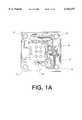
- FIG. 1ais a plan view of the printed circuit board component shown in FIG. 1;
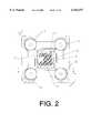
- FIG. 2is a bottom view of the colorimeter shown in FIG. 1;
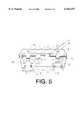
- FIG. 3is a sectional view of the colorimeter shown in FIGS. 1 and 2, the section being taken along the line 3--3 in FIG. 4;
- FIG. 4is a sectional view of the colorimeter shown in FIG. 1, the section being taken along the line 4--4 in FIG. 2;
- FIG. 5is a sectional view of the colorimeter show in the preceding figures, the section being taken along the line 5--5 in FIG. 2;
- FIGS. 6 and 7are ray diagrams illustrating how the apertures in the wall of the colorimeter through which light passes masks and restricts the field of view of the filter/photodetector pairs;
- FIG. 8is an exploded view in perspective of the filter unit used in the colorimeter shown in the preceding figures.
- FIG. 9is a sectional view of the filter unit illustrating the laminated relationship of the layers thereof.
- FIG. 10is a block diagram schematically showing the circuitry of the colorimeter and the system for calibrating a monitor utilizing the outputs from the colorimeter;
- FIG. 11is a flow chart illustrating programming of the microprocessor shown in FIG. 10 to obtain refresh rate probes
- FIG. 12is a flow chart illustrating the programming of the microprocessor to synthesize the response of the colorimeter and provide a response mimicking the CIE color matching functions;
- FIGS. 13, 14 and 15are curves illustrating the filter transmisivity over the spectrum, the detector filter pair responsivity over the spectrum and the accuracy of mimicking the responsivity to the color matching functions.
- the colorimeteris a unitary assembly of a housing 10 made up of a front shell 12 and a rear shell 14 which are joined at a tongue and groove connection 16.
- a generally rectangular recessed wall 18has a matrix of apertures 20 which may be evenly spaced from each other by the same distances along X and Y coordinates paralleling perpendicular edges of the wall 18.
- the shape of the aperturesis oblong and their longitudinal axes are at approximately 45° to the X and Y coordinates, that is to the edges of the wall 18.
- the longitudinal axisis arranged, when the colorimeter is in use in making colormetric measurements of a color monitor screen, at approximately 45° from horizontal. This enables sufficient light (photons) to pass through the apertures even with limited fields of view. Such limitation in the field of view is discussed in connection with FIGS. 6 and 7 below.
- the fields of view of each of the apertures 20are designed to avoid cross-talk between different photodetector 38 and filters 50 (discussed in greater detail below).
- the constrained fields of viewavoid the effect of color changes with angle, especially in the vertical direction which occurs with LCD screens. It has been found that oblong apertures with parallel sides and circular ends in the orientation discussed above, suitably restrict the fields of view.
- the front shell 12has features 22 projecting inwardly at each of the four corners of the shell 12. These features have circular tongues 24 which capture retaining grooves in soft, rubber suction cups 26.
- the suction cupsprovide light pressure against the screen of color monitor or display, from which light enters the colorimeter via the apertures 20.
- the printed circuit boardhas an array of photodetectors 38 matching the array of apertures 20 in number and positional relationship.
- Extending from the back wall of the shell 14are a matrix of ribs 40, some of which, 42, extend a distance sufficient to bring these ribs 42 into contact with the backside of the printed circuit board 32.
- These ribs 42form generally rectangular compartments which enclose the photodetectors 38 and prevent leakage of light therebetween, thereby further eliminating crosstalk between light passing through the apertures 20 and reaching the photodetectors 38.
- the ribs 40also serve to strengthen the shell 14.
- the photodetectors 38are preferably light-to-frequency converters which combine a photodiode and a current-to-frequency converter on a single chip. Such devices are available from Texas Instruments of Dallas, Tex., under such part numbers as TSL 235. They provide digital outputs (pulse trains), the repetition rate or frequency of which is proportional to light level.
- the printed circuit board 32has an array of openings 44 which are in the same spatial relationship as the apertures 20 and are disposed along optical axes through the center of the apertures 20, as may be observed in FIG. 2 as well as in FIG. 4.
- the board 32has printed wiring and electrical components, such as resistors and integrated circuit (IC) chips 48, mounted on the side of the board 32 facing the apertures 20.
- the photodetectors 38are mounted on the opposite side of the board.
- An optical filter pack 50is mounted on the side of the board 32 facing the apertured wall 18.
- the filter packis a laminated, layered structure which is illustrated in FIGS. 8 and 9. There are 7 sheets of filter material, A to G. These may be composed of gelatin and each provides a different long-pass or edge-type optical filter.
- Such gelatin filtersare much lower in cost than thin-film filters which are used in most contemporary colorimeters. Filters employing transmissive colored inks may also be used.
- the filtersare retained in a layered structure having openings in like positional relationship to the apertures 18 and the holes 44 so that when the filter 50 is mounted on the board 32, the filter elements A through G are aligned with different ones of the holes.
- One of the holes in the layers laminated with the elements A to Gis over an unmasked area M. This is the area and the hole 44 in aperture 20 approximately in the middle of the filter array.
- the notch 52provides edges which facilitate placement and alignment of the filter pack 50 on the board 32.
- the layers, which constitute the packare opaque (e.g., are black) layers H of a material such as polycarbonate sheet which are on the outside of the pack.
- One of these layersfaces downwardly and the other may be covered by an adhesive layer L on the outside of the back.
- the adhesivemay be a pressure-sensitive adhesive, which itself may be covered by release material so as to facilitate assembly of the filter pack 50 on the board 32.
- the filter packmay be reproduced in quantity, reliably and with accurate spacings and tolerances.
- the photodetectorshave lens elements 56 in front of the photodiodes thereof which enhance the amount of light collected (i.e., passing via the filter elements in the filter pack 50).
- the apertures 20subtend arcs of 30° (plus or minus 15°) along the vertical and 44° (plus or minus 22°) along the horizontal. The light from vertically spaced regions is therefore masked as shown by the curve 58 in FIG.
- the colorimetry systemis shown in FIG. 10. This figure also shows how the colorimeter is used for calibrating a monitor so as to provide accurate color and gamma, in accordance with the CIE XYZ color system.
- the colorimeter systemmay be adapted to utilize other color systems such as the CIE L*a*b* and the CIE Luv color systems, if desired.
- the monitor under testmay be a cathode ray tube monitor or an LCD monitor or display. In the event that a cathode ray tube monitor is used, it is desirable to make measurements over a large number, say 40 or more, refresh cycles or frames of the image. To that end, the refresh rate is detected in a microprocessor 60 of the system which may be programmed as shown in the flowchart of FIG. 11.
- An area or patch of the monitor screen equal to the area of the wall 18 carrying the apertures 20 (for example 1 inch square)is exposed to light from the monitor.
- the lightpasses through the edge filters of the pack 50 into the detectors 38.
- the detectorsprovide a digital output in the form of a pulse train of rate which depends upon the light intensity. By collecting or counting the pulses over intervals of time which may be related to the refresh rate, in the case of cathode ray tube monitors, digital outputs representing the light passing through each edge filter, as well as the unfiltered light, is obtained.
- the detectors 38have their outputs multiplexed by a multiplexer 62 which provide trains of pulses sequentially over like intervals as provided for by the channel selector output from the microprocessor 60.
- the unfiltered light from the 8th detector 38provides an output which is used for detecting refresh rate, as well as an effective edge filter output, which is used in synthesizing the response mimicking the CIE color system, namely the color matching functions.
- the microprocessoris connected to a host computer and particularly the CPU 64 thereof by a communications link such as the USB (Universal Serial Bus) or other communications link, for example an RS232 bus.
- the CPU 64may communicate with the microprocessor 60 in order to retrieve the color measurements.
- the CPUmay first flash an all-red screen and instruct the microprocessor to extract spectral data.
- the CPUmay then present entirely green, then blue screens, as well as multiple levels of a gray screen, varying from completely dark (red, green and blue controls at maximum).
- the refresh rateis obtained from the 8th detector output.
- the frequency or pulse repetition rate of the detector outputis measured.
- a counter Ais started.
- the frequencycontinues to be measured until there is a rise in count rate, indicating a frequency or rate minimum.
- the counteris stopped.
- the refresh rateis thus detected at the high and low luminosity from the screen.
- This refresh ratemay be used to control the sampling window of the multiplexer as well as to collect counts from each of the detectors during the colorimetry process.
- FIG. 12shows how the microprocessor 60 is programmed to mimic the z color matching function.
- the other color matching functionsmay be obtained by a similar program.
- the programuses different coefficients for the x, y and z functions.
- the computationscarry out the equations set forth below for each filter detector pair, including the filter detector pair F/D0 which passes essentially the entire visible spectrum, while the other filter detector pairs pass successively smaller wavelength regions at the upper end of the spectrum.
- the regionsare overlapping in that the portion of the spectrum passed by the upper edge filter detector pair of the 7th band (channel CHN-7) is overlapped, while only the first band (channel CHN-1) is overlapped by the unfiltered band or channel (CHN-0), that is the output from the F/D0 filter detector pair.
- the table of coefficientsis, in general, set forth as the following table. It is a two-dimensional array of numbers stored in the microprocessor 60. These numbers are used as the coefficients in the algorithm set forth in the equations given below.
- a two-dimensional array of numbersis stored in the microprocessor. These numbers are to be used as coefficients, C an * in the algorithm. They are:
- the co-efficientsare derived by a least mean square fit to the color matching functions.
- the methodology which is usedis described in a paper by D. O. Wharmby, entitled “Improvements in the Use of Filter Colorimeters” which appeared in the Journal of Physics, E. Scientific Instruments, 1975, Vol. 8, pages 41-44. In the Wharmby article, an attempt was made to mimic the functions using only six band pass filters. In accordance with the present invention, long pass or edge filters are used, which not only make the response which is precisely mimicked, but also enables the use of low cost edge filters, rather than band pass filters to pass the red, green and blue portions of the spectrum, respectively.
- long-pass filtersallows the freedom to select individual filters to match individual slopes of the CIE x y z (bar) curves.
- a band-pass filter setforces one to make compromises on one slope to try to match a different slope of the same function.
- the response of the edge filtersis shown in FIG. 13 for the unfiltered band and the band passed through the various filters in the filter pack 50.
- the slope of the skirts (rising edges) particularly for band 4 and 5,have been selected to facilitate the derivation of the coefficients to accurately mimic the color matching functions.
- the color matching functionsare shown in FIG. 15 and the accuracy of the synthesized color matching functions (that is, how they compare to the ideal color matching functions) is shown in FIG. 15.
- FIG. 14illustrates the responsivity of the filter detector pairs.
- the detectorimposes its own responsivity on the output which is obtained via the filters.
- the affect of the detector responsivityis that the filter/detector pair responsivity is the product of the detector responsivity with the filter transmission characteristics.
Landscapes
- Physics & Mathematics (AREA)
- Spectroscopy & Molecular Physics (AREA)
- General Physics & Mathematics (AREA)
- Engineering & Computer Science (AREA)
- Human Computer Interaction (AREA)
- Spectrometry And Color Measurement (AREA)
Abstract
Description
______________________________________ N X Y Z ______________________________________ F/D0 CX0 CY0 CZ0 F/D1 CX1 CY1 CZ1 F/D2 CX2 CY2 CZ2 F/D3 CX3 CY3 CZ3 F/D4 CX4 CY4 CZ4 F/D5 CX5 CY5 CZ5 F/D6 CX6 CY6 CZ6 F/D7 CX7 CY7 CZ7 ______________________________________ ALGORITHM M ______________________________________ X () = FD.sub.0 * C.sub.X0 + FD.sub.1 * C.sub.X1 + FD.sub.2 * C.sub.X2. . . + FD.sub.7 * C.sub.Y7 Y () = FD.sub.0 * C.sub.Y0 + FD.sub.1 * C.sub.Y1 + FD.sub.2 * C.sub.Y2. . . + FD.sub.7 * C.sub.Y7 Z () = FD.sub.0 * C.sub.Z0 + FD.sub.1 * C.sub.Z1 + FD.sub.2 * C.sub.Z2. . . + FD.sub.7 * C.sub.Z7 ______________________________________
______________________________________ Example of Coefficients CX0 = -0.00097 CY0 = -0.00049 CZ0 = -0.0109 CX1 = 0.00961 CY1 = 0.00019 CZ1 = 0.07038 CX2 = 0.03507 CY2 = 0.0036 CZ2 = 0.15586 CX3 = -0.044 CY3 = 0.00214 CZ3 = -0.15754 CX4 = -0.01173 CY4 = 0.07195 CZ4 = -0.07174 CX5 = 0.13641 CY5 = -0.05846 CZ5 = 0.03593 CX6 = -0.06319 CY6 = -0.01143 CZ6 = -0.01658 CX7 = -0.05372 CY7 = -0.0134 CZ7 = 0.0009 ______________________________________
Claims (44)
Priority Applications (8)
| Application Number | Priority Date | Filing Date | Title |
|---|---|---|---|
| US09/360,051US6163377A (en) | 1999-07-23 | 1999-07-23 | Colorimeter |
| PCT/US2000/019752WO2001007880A1 (en) | 1999-07-23 | 2000-07-20 | Colorimeter |
| JP2001512261AJP2003505687A (en) | 1999-07-23 | 2000-07-20 | Colorimeter |
| CA002380418ACA2380418A1 (en) | 1999-07-23 | 2000-07-20 | Colorimeter |
| CNB008133344ACN1250946C (en) | 1999-07-23 | 2000-07-20 | Colorimeter |
| AU61143/00AAU6114300A (en) | 1999-07-23 | 2000-07-20 | Colorimeter |
| EP00947559AEP1196745A4 (en) | 1999-07-23 | 2000-07-20 | Colorimeter |
| US09/650,182US6816262B1 (en) | 1999-07-23 | 2000-08-29 | Colorimeter having field programmable gate array |
Applications Claiming Priority (1)
| Application Number | Priority Date | Filing Date | Title |
|---|---|---|---|
| US09/360,051US6163377A (en) | 1999-07-23 | 1999-07-23 | Colorimeter |
Related Child Applications (1)
| Application Number | Title | Priority Date | Filing Date |
|---|---|---|---|
| US09/650,182Continuation-In-PartUS6816262B1 (en) | 1999-07-23 | 2000-08-29 | Colorimeter having field programmable gate array |
Publications (1)
| Publication Number | Publication Date |
|---|---|
| US6163377Atrue US6163377A (en) | 2000-12-19 |
Family
ID=23416392
Family Applications (2)
| Application Number | Title | Priority Date | Filing Date |
|---|---|---|---|
| US09/360,051Expired - LifetimeUS6163377A (en) | 1999-07-23 | 1999-07-23 | Colorimeter |
| US09/650,182Expired - Fee RelatedUS6816262B1 (en) | 1999-07-23 | 2000-08-29 | Colorimeter having field programmable gate array |
Family Applications After (1)
| Application Number | Title | Priority Date | Filing Date |
|---|---|---|---|
| US09/650,182Expired - Fee RelatedUS6816262B1 (en) | 1999-07-23 | 2000-08-29 | Colorimeter having field programmable gate array |
Country Status (7)
| Country | Link |
|---|---|
| US (2) | US6163377A (en) |
| EP (1) | EP1196745A4 (en) |
| JP (1) | JP2003505687A (en) |
| CN (1) | CN1250946C (en) |
| AU (1) | AU6114300A (en) |
| CA (1) | CA2380418A1 (en) |
| WO (1) | WO2001007880A1 (en) |
Cited By (31)
| Publication number | Priority date | Publication date | Assignee | Title |
|---|---|---|---|---|
| US20030058448A1 (en)* | 2001-09-21 | 2003-03-27 | Merle Cormic K. | Colorimeter |
| US6590648B1 (en)* | 1999-07-06 | 2003-07-08 | Gretag-Macbeth Ag | Apparatus for measuring light |
| US20040075032A1 (en)* | 2002-10-15 | 2004-04-22 | Lutz Carl David | Sensor with suction cup array mount |
| US20040080749A1 (en)* | 2002-10-15 | 2004-04-29 | Lutz Carl David | Colorimeter with single cable low impact mounting system |
| US20040114144A1 (en)* | 2002-12-11 | 2004-06-17 | Lutz Carl David | Colorimeter with high SNR |
| US6816262B1 (en)* | 1999-07-23 | 2004-11-09 | Colorvision Administrative Ag | Colorimeter having field programmable gate array |
| US20050078305A1 (en)* | 2000-12-18 | 2005-04-14 | Colorvision Administrative Ag | Monitor calibrator |
| US20060082776A1 (en)* | 2004-09-30 | 2006-04-20 | Lianza Thomas A | Method and apparatus for improved colorimetry |
| US20060103864A1 (en)* | 2004-11-16 | 2006-05-18 | Datacolor Holding Ag | Method for designing a colorimeter having integral CIE color-matching filters |
| US20060119849A1 (en)* | 2004-11-17 | 2006-06-08 | Brian Levey | Tristimulus colorimeter having integral dye filters |
| US20060215193A1 (en)* | 2005-03-23 | 2006-09-28 | Colman Shannon | Method for designing a colorimeter having illuminant-weighted CIE color-matching filters |
| US20060215162A1 (en)* | 2005-03-23 | 2006-09-28 | Colman Shannon | Reflectance sensor for integral illuminant-weighted CIE color matching filters |
| US20070188764A1 (en)* | 2005-08-15 | 2007-08-16 | Nisper Jon K | Optical instrument and components thereof |
| US20070279390A1 (en)* | 2006-06-01 | 2007-12-06 | Dmitrii Loukianov | Method and apparatus for automatic screen calibration and color reproduction in a display system |
| US20080180671A1 (en)* | 2007-01-25 | 2008-07-31 | Len-Li Kevin Lim | Methods and apparatus for estimating the intensity of one spectrum of light in a mixed light, in response to the sensed intensities of one or more other spectrums of light in the mixed light |
| US20090141042A1 (en)* | 2007-11-29 | 2009-06-04 | Colman Shannon | Method and apparatus for calibrating a display-coupled color measuring device |
| US20100091270A1 (en)* | 2008-10-10 | 2010-04-15 | Konica Minolta Sensing, Inc. | Optical property measurement apparatus |
| US20100128052A1 (en)* | 2008-11-25 | 2010-05-27 | Samsung Electronics Co., Ltd. | Method and apparatus for calibrating a color temperature of a projector |
| CN102033065A (en)* | 2010-11-27 | 2011-04-27 | 大连大学 | Digital colorimetric method for measuring cyanide concentration in environment and biological sample |
| US20110141472A1 (en)* | 2008-08-15 | 2011-06-16 | Koninklijke Philips Electronics N.V. | Monitoring light coming from different areas |
| US8472012B2 (en) | 1997-01-02 | 2013-06-25 | Jjl Technologies Llc | Apparatus having a first optical sensor making a first measurement to detect position and a second optical sensor making a second measurement |
| US8717567B2 (en) | 2011-08-31 | 2014-05-06 | Datacolor Holding Ag | Method and apparatus for calibrating a color measurement device |
| US8786844B2 (en) | 1998-06-30 | 2014-07-22 | 511 Innovations, Inc. | Apparatus for measuring optical characteristics including position detection |
| US8792097B2 (en) | 1996-01-02 | 2014-07-29 | 511 Innovations, Inc. | Systems for applying pigment to a substrate with a spectrophotometer integral to the system |
| US8817243B2 (en) | 1996-01-02 | 2014-08-26 | 511 Innovations, Inc. | Apparatus and method for measuring color |
| US8998613B2 (en) | 1997-01-02 | 2015-04-07 | 511 Innovations Inc. | Apparatus and method for measuring optical characteristics using a camera and a calibration chart imaged with the camera |
| US20170191869A1 (en)* | 2015-12-31 | 2017-07-06 | Chicony Power Technology Co., Ltd. | Light Sensor |
| US9952102B1 (en) | 2017-04-19 | 2018-04-24 | Datacolor, Inc. | Method and apparatus for calibrating a color measurement instrument |
| US10488264B2 (en) | 2014-09-11 | 2019-11-26 | Ams Sensors Singapore Pte. Ltd. | Determining spectral emission characteristics of incident radiation |
| CN111551266A (en)* | 2020-05-25 | 2020-08-18 | 吉林求是光谱数据科技有限公司 | Environmental color temperature testing method and system based on multispectral image detection technology |
| US20240104795A1 (en)* | 2022-09-23 | 2024-03-28 | Susan JANECZKO | System and method for color palette analysis and creation |
Families Citing this family (27)
| Publication number | Priority date | Publication date | Assignee | Title |
|---|---|---|---|---|
| US7064740B2 (en) | 2001-11-09 | 2006-06-20 | Sharp Laboratories Of America, Inc. | Backlit display with improved dynamic range |
| JP2007525858A (en)* | 2003-04-15 | 2007-09-06 | センサーズ・フォー・メデセン・アンド・サイエンス・インコーポレーテッド | Printed circuit device with integrated antenna and implantable sensor processing device with printed integrated circuit board antenna |
| WO2005052673A2 (en)* | 2003-11-21 | 2005-06-09 | Sharp Laboratories Of America, Inc. | Liquid crystal display with adaptive color |
| US7612757B2 (en) | 2004-05-04 | 2009-11-03 | Sharp Laboratories Of America, Inc. | Liquid crystal display with modulated black point |
| US7777714B2 (en) | 2004-05-04 | 2010-08-17 | Sharp Laboratories Of America, Inc. | Liquid crystal display with adaptive width |
| US7602369B2 (en) | 2004-05-04 | 2009-10-13 | Sharp Laboratories Of America, Inc. | Liquid crystal display with colored backlight |
| US8395577B2 (en) | 2004-05-04 | 2013-03-12 | Sharp Laboratories Of America, Inc. | Liquid crystal display with illumination control |
| US7872631B2 (en) | 2004-05-04 | 2011-01-18 | Sharp Laboratories Of America, Inc. | Liquid crystal display with temporal black point |
| US7532192B2 (en) | 2004-05-04 | 2009-05-12 | Sharp Laboratories Of America, Inc. | Liquid crystal display with filtered black point |
| US7505018B2 (en) | 2004-05-04 | 2009-03-17 | Sharp Laboratories Of America, Inc. | Liquid crystal display with reduced black level insertion |
| US7023451B2 (en) | 2004-06-14 | 2006-04-04 | Sharp Laboratories Of America, Inc. | System for reducing crosstalk |
| JP4138708B2 (en)* | 2004-07-12 | 2008-08-27 | 浜松ホトニクス株式会社 | Photodetector |
| US7898519B2 (en) | 2005-02-17 | 2011-03-01 | Sharp Laboratories Of America, Inc. | Method for overdriving a backlit display |
| US7525528B2 (en) | 2004-11-16 | 2009-04-28 | Sharp Laboratories Of America, Inc. | Technique that preserves specular highlights |
| US8050511B2 (en) | 2004-11-16 | 2011-11-01 | Sharp Laboratories Of America, Inc. | High dynamic range images from low dynamic range images |
| US8050512B2 (en) | 2004-11-16 | 2011-11-01 | Sharp Laboratories Of America, Inc. | High dynamic range images from low dynamic range images |
| US9143657B2 (en) | 2006-01-24 | 2015-09-22 | Sharp Laboratories Of America, Inc. | Color enhancement technique using skin color detection |
| US8121401B2 (en) | 2006-01-24 | 2012-02-21 | Sharp Labortories of America, Inc. | Method for reducing enhancement of artifacts and noise in image color enhancement |
| US8941580B2 (en) | 2006-11-30 | 2015-01-27 | Sharp Laboratories Of America, Inc. | Liquid crystal display with area adaptive backlight |
| US8035688B2 (en)* | 2007-07-19 | 2011-10-11 | Xerox Corporation | Method, system and apparatus for jointly calibrating color digital cameras and monitors |
| DE102008024005A1 (en) | 2008-05-17 | 2009-12-17 | Basiccolor Gmbh | Colorimeter and method for calibrating a colorimeter |
| US20100208266A1 (en)* | 2009-02-17 | 2010-08-19 | Colman Shannon | Tristimulus colorimeter having integral dye filters |
| JPWO2012005350A1 (en)* | 2010-07-09 | 2013-09-05 | 千代田電子工業株式会社 | Non-destructive measuring device for fruits and vegetables |
| KR102065403B1 (en)* | 2013-04-26 | 2020-01-13 | 엘지전자 주식회사 | caliartor |
| US20150268985A1 (en)* | 2014-03-24 | 2015-09-24 | Freescale Semiconductor, Inc. | Low Latency Data Delivery |
| EP3021096B1 (en)* | 2014-11-11 | 2017-04-05 | Instrument Systems Optische Messtechnik Gmbh | Colorimeter calibration |
| CN107340060B (en)* | 2017-06-27 | 2020-01-10 | 上海集成电路研发中心有限公司 | Infrared sensor structure, preparation method and detection system |
Citations (27)
| Publication number | Priority date | Publication date | Assignee | Title |
|---|---|---|---|---|
| US3645633A (en)* | 1971-01-11 | 1972-02-29 | Us Army | Chromacorder |
| US3804531A (en)* | 1967-10-02 | 1974-04-16 | T Kosaka | Color analyzer |
| US3998555A (en)* | 1973-10-18 | 1976-12-21 | Genevieve I. Hanscom | Color grading apparatus |
| US4150898A (en)* | 1977-02-02 | 1979-04-24 | Shigeru Suga | Colorimeter employing primary filter mirrors |
| US4334782A (en)* | 1980-08-25 | 1982-06-15 | Westinghouse Electric Corp. | Method and apparatus for expressing relative brightness of artificial illumination as perceived by the average observer |
| US4401611A (en)* | 1981-11-12 | 1983-08-30 | Congoleum Corporation | Embossing of foamable plastisols on dry blend layers |
| US4551748A (en)* | 1982-02-26 | 1985-11-05 | International Standard Electric Corporation | Measuring head for determining the color purity and the convergence in a color picture tube |
| US4643568A (en)* | 1984-04-05 | 1987-02-17 | Telefonaktiebolaget Lm Ericsson | Method and apparatus for measuring the illuminating power of incident light |
| US4653925A (en)* | 1985-08-23 | 1987-03-31 | Thornton Jr William A | Method and apparatus for measuring any of a large number of characteristics of lamplight |
| US4758085A (en)* | 1985-10-16 | 1988-07-19 | Bertin & Cie | Optical fiber spectrometer/colorimeter apparatus |
| US4773761A (en)* | 1985-12-16 | 1988-09-27 | Minolta Camera Kabushiki Kaisha | Photoelectric colorimeter |
| US4834541A (en)* | 1987-01-22 | 1989-05-30 | Agency Of Industrial Science & Technology | Color sensor |
| US4902136A (en)* | 1987-10-26 | 1990-02-20 | Siemens Aktiengesellschaft | Arrangement for high-resolution spectroscopy |
| US4989982A (en)* | 1988-08-05 | 1991-02-05 | Minolta Camera Kabushiki Kaisha | Spectral sensitivity correcting device in a photoelectric tristimulus colorimeter |
| US5168320A (en)* | 1989-03-13 | 1992-12-01 | Lutz Carl D | Colorimeter |
| US5272518A (en)* | 1990-12-17 | 1993-12-21 | Hewlett-Packard Company | Colorimeter and calibration system |
| US5477326A (en)* | 1994-06-30 | 1995-12-19 | Bayer Corporation | Spectrophotometer arrangement with multi-detector readhead |
| US5499040A (en)* | 1994-06-27 | 1996-03-12 | Radius Inc. | Method and apparatus for display calibration and control |
| US5537516A (en)* | 1994-03-15 | 1996-07-16 | Electronics For Imaging, Inc. | Method for calibrating a color printer using a scanner for color measurements |
| US5739914A (en)* | 1996-11-12 | 1998-04-14 | Yokogawa Instrument Corporation | Colorimetric instrument |
| US5745229A (en)* | 1996-01-02 | 1998-04-28 | Lj Laboratories, L.L.C. | Apparatus for determining optical characteristics of an object |
| US5757438A (en)* | 1994-08-04 | 1998-05-26 | Lg Electronics Inc. | Apparatus for compensating for image display characteristics |
| US5792049A (en)* | 1996-01-17 | 1998-08-11 | Spectrx, Inc. | Spectroscopic system with disposable calibration device |
| US5818586A (en)* | 1994-10-31 | 1998-10-06 | Valtion Teknillinen Tutkimuskeskus | Miniaturized fabry-perot spectrometer for optical analysis |
| WO1999010866A1 (en)* | 1997-08-25 | 1999-03-04 | Imagicolor Corp | A system for distributing and controlling color reproduction at multiple sites |
| US5892585A (en)* | 1996-05-05 | 1999-04-06 | Sequel Imaging | Colorimeter for measurement of temporally variant light sources |
| US5926282A (en)* | 1995-09-27 | 1999-07-20 | Fraunhofer-Gesellschaft Zur Forderung Der Angewandten Forschung E.V. | Multispectral sensor device |
Family Cites Families (7)
| Publication number | Priority date | Publication date | Assignee | Title |
|---|---|---|---|---|
| DE2122655A1 (en)* | 1971-05-07 | 1972-11-30 | Max Planck Gesellschaft | Optical absorption device for determining the concentration of a component of a substance mixture |
| US4134683A (en)* | 1976-03-05 | 1979-01-16 | The United States Of America As Represented By The Administrator Of The National Aeronautics And Space Administration | Multispectral imaging and analysis system |
| US4431918A (en)* | 1981-03-27 | 1984-02-14 | Honeywell Inc. | Etchable glass cold shield for background limited detectors |
| US5191409A (en)* | 1988-03-29 | 1993-03-02 | Mitsubishi Denki Kabushiki Kaisha | Color scanning system |
| WO1997003444A1 (en)* | 1995-07-10 | 1997-01-30 | Xilinx, Inc. | System comprising field programmable gate array and intelligent memory |
| US6226034B1 (en)* | 1997-05-06 | 2001-05-01 | Roper Scientificomasd, Inc. | Spatial non-uniformity correction of a color sensor |
| US6163377A (en)* | 1999-07-23 | 2000-12-19 | Cv Us, Inc. | Colorimeter |
- 1999
- 1999-07-23USUS09/360,051patent/US6163377A/ennot_activeExpired - Lifetime
- 2000
- 2000-07-20EPEP00947559Apatent/EP1196745A4/ennot_activeWithdrawn
- 2000-07-20CNCNB008133344Apatent/CN1250946C/ennot_activeExpired - Fee Related
- 2000-07-20CACA002380418Apatent/CA2380418A1/ennot_activeAbandoned
- 2000-07-20WOPCT/US2000/019752patent/WO2001007880A1/enactiveApplication Filing
- 2000-07-20AUAU61143/00Apatent/AU6114300A/ennot_activeAbandoned
- 2000-07-20JPJP2001512261Apatent/JP2003505687A/enactivePending
- 2000-08-29USUS09/650,182patent/US6816262B1/ennot_activeExpired - Fee Related
Patent Citations (28)
| Publication number | Priority date | Publication date | Assignee | Title |
|---|---|---|---|---|
| US3804531A (en)* | 1967-10-02 | 1974-04-16 | T Kosaka | Color analyzer |
| US3645633A (en)* | 1971-01-11 | 1972-02-29 | Us Army | Chromacorder |
| US3998555A (en)* | 1973-10-18 | 1976-12-21 | Genevieve I. Hanscom | Color grading apparatus |
| US4150898A (en)* | 1977-02-02 | 1979-04-24 | Shigeru Suga | Colorimeter employing primary filter mirrors |
| US4334782A (en)* | 1980-08-25 | 1982-06-15 | Westinghouse Electric Corp. | Method and apparatus for expressing relative brightness of artificial illumination as perceived by the average observer |
| US4401611A (en)* | 1981-11-12 | 1983-08-30 | Congoleum Corporation | Embossing of foamable plastisols on dry blend layers |
| US4551748A (en)* | 1982-02-26 | 1985-11-05 | International Standard Electric Corporation | Measuring head for determining the color purity and the convergence in a color picture tube |
| US4643568A (en)* | 1984-04-05 | 1987-02-17 | Telefonaktiebolaget Lm Ericsson | Method and apparatus for measuring the illuminating power of incident light |
| US4653925A (en)* | 1985-08-23 | 1987-03-31 | Thornton Jr William A | Method and apparatus for measuring any of a large number of characteristics of lamplight |
| US4758085A (en)* | 1985-10-16 | 1988-07-19 | Bertin & Cie | Optical fiber spectrometer/colorimeter apparatus |
| US4773761A (en)* | 1985-12-16 | 1988-09-27 | Minolta Camera Kabushiki Kaisha | Photoelectric colorimeter |
| US4834541A (en)* | 1987-01-22 | 1989-05-30 | Agency Of Industrial Science & Technology | Color sensor |
| US4902136A (en)* | 1987-10-26 | 1990-02-20 | Siemens Aktiengesellschaft | Arrangement for high-resolution spectroscopy |
| US4989982A (en)* | 1988-08-05 | 1991-02-05 | Minolta Camera Kabushiki Kaisha | Spectral sensitivity correcting device in a photoelectric tristimulus colorimeter |
| US5168320A (en)* | 1989-03-13 | 1992-12-01 | Lutz Carl D | Colorimeter |
| US5272518A (en)* | 1990-12-17 | 1993-12-21 | Hewlett-Packard Company | Colorimeter and calibration system |
| US5537516A (en)* | 1994-03-15 | 1996-07-16 | Electronics For Imaging, Inc. | Method for calibrating a color printer using a scanner for color measurements |
| US5499040A (en)* | 1994-06-27 | 1996-03-12 | Radius Inc. | Method and apparatus for display calibration and control |
| US5477326A (en)* | 1994-06-30 | 1995-12-19 | Bayer Corporation | Spectrophotometer arrangement with multi-detector readhead |
| US5757438A (en)* | 1994-08-04 | 1998-05-26 | Lg Electronics Inc. | Apparatus for compensating for image display characteristics |
| US5818586A (en)* | 1994-10-31 | 1998-10-06 | Valtion Teknillinen Tutkimuskeskus | Miniaturized fabry-perot spectrometer for optical analysis |
| US5926282A (en)* | 1995-09-27 | 1999-07-20 | Fraunhofer-Gesellschaft Zur Forderung Der Angewandten Forschung E.V. | Multispectral sensor device |
| US5745229A (en)* | 1996-01-02 | 1998-04-28 | Lj Laboratories, L.L.C. | Apparatus for determining optical characteristics of an object |
| US5883708A (en)* | 1996-01-02 | 1999-03-16 | Lj Laboratories, L.L.C. | Apparatus for measuring optical properties |
| US5792049A (en)* | 1996-01-17 | 1998-08-11 | Spectrx, Inc. | Spectroscopic system with disposable calibration device |
| US5892585A (en)* | 1996-05-05 | 1999-04-06 | Sequel Imaging | Colorimeter for measurement of temporally variant light sources |
| US5739914A (en)* | 1996-11-12 | 1998-04-14 | Yokogawa Instrument Corporation | Colorimetric instrument |
| WO1999010866A1 (en)* | 1997-08-25 | 1999-03-04 | Imagicolor Corp | A system for distributing and controlling color reproduction at multiple sites |
Non-Patent Citations (4)
| Title |
|---|
| D.D. Wharmby, Journal of Physics, E: Scientific Instruments, 1975, vol. 8, pp. 41 44.* |
| D.D. Wharmby, Journal of Physics, E: Scientific Instruments, 1975, vol. 8, pp. 41-44. |
| R.W.G. Hunt, Measuring Color, 2nd Edition, Ellis Horwood Ltd. Publisher, 1991, pp. 178 181.* |
| R.W.G. Hunt, Measuring Color, 2nd Edition, Ellis Horwood Ltd. Publisher, 1991, pp. 178-181. |
Cited By (56)
| Publication number | Priority date | Publication date | Assignee | Title |
|---|---|---|---|---|
| US8792097B2 (en) | 1996-01-02 | 2014-07-29 | 511 Innovations, Inc. | Systems for applying pigment to a substrate with a spectrophotometer integral to the system |
| US8817243B2 (en) | 1996-01-02 | 2014-08-26 | 511 Innovations, Inc. | Apparatus and method for measuring color |
| US8472012B2 (en) | 1997-01-02 | 2013-06-25 | Jjl Technologies Llc | Apparatus having a first optical sensor making a first measurement to detect position and a second optical sensor making a second measurement |
| US8998613B2 (en) | 1997-01-02 | 2015-04-07 | 511 Innovations Inc. | Apparatus and method for measuring optical characteristics using a camera and a calibration chart imaged with the camera |
| US8786844B2 (en) | 1998-06-30 | 2014-07-22 | 511 Innovations, Inc. | Apparatus for measuring optical characteristics including position detection |
| US6590648B1 (en)* | 1999-07-06 | 2003-07-08 | Gretag-Macbeth Ag | Apparatus for measuring light |
| US6816262B1 (en)* | 1999-07-23 | 2004-11-09 | Colorvision Administrative Ag | Colorimeter having field programmable gate array |
| US7027140B2 (en)* | 2000-12-18 | 2006-04-11 | Colorvision Administrative Ag | Monitor calibrator |
| US7072033B2 (en)* | 2000-12-18 | 2006-07-04 | Datacolor Holding Ag | Monitor calibrator |
| US20050078305A1 (en)* | 2000-12-18 | 2005-04-14 | Colorvision Administrative Ag | Monitor calibrator |
| US20070008535A1 (en)* | 2001-09-21 | 2007-01-11 | Datacolor Holding Ag | Colorimeter |
| US20040263847A1 (en)* | 2001-09-21 | 2004-12-30 | Merle Cormic K. | Colorimeter |
| US20030058448A1 (en)* | 2001-09-21 | 2003-03-27 | Merle Cormic K. | Colorimeter |
| US7391514B2 (en) | 2001-09-21 | 2008-06-24 | Datacolor Holding Ag | Colorimeter |
| US7133133B2 (en) | 2001-09-21 | 2006-11-07 | Datacolor Holding Ag | Colorimeter |
| US6784995B2 (en) | 2001-09-21 | 2004-08-31 | Colorvision Administrative Ag | Colorimeter |
| US7064831B2 (en) | 2002-10-15 | 2006-06-20 | Gretagmacbeth, Llc | Colorimeter with single cable low impact mounting system |
| US6880790B2 (en) | 2002-10-15 | 2005-04-19 | Gretagmacbeth, Llc | Sensor with suction cup array mount |
| EP1551251A4 (en)* | 2002-10-15 | 2011-08-03 | Gretagmacbeth L L C | Sensor with suction cup array mount |
| US20040075032A1 (en)* | 2002-10-15 | 2004-04-22 | Lutz Carl David | Sensor with suction cup array mount |
| US20040080749A1 (en)* | 2002-10-15 | 2004-04-29 | Lutz Carl David | Colorimeter with single cable low impact mounting system |
| EP1588132A4 (en)* | 2002-10-15 | 2008-03-05 | Gretagmacbeth Llc | Colorimeter with single cable low impact mounting system |
| WO2004053436A3 (en)* | 2002-12-11 | 2005-03-17 | Sequel Imaging Inc | Colorimeter with high snr |
| US7030987B2 (en)* | 2002-12-11 | 2006-04-18 | Gretagmacbeth, Llc | Colorimeter with high SNR |
| US20040114144A1 (en)* | 2002-12-11 | 2004-06-17 | Lutz Carl David | Colorimeter with high SNR |
| US20060082776A1 (en)* | 2004-09-30 | 2006-04-20 | Lianza Thomas A | Method and apparatus for improved colorimetry |
| US7372571B2 (en)* | 2004-09-30 | 2008-05-13 | Gretegmacbeth, Llc | Color sensing apparatus |
| US7420680B2 (en) | 2004-11-16 | 2008-09-02 | Datacolor Holding Ag | Method for designing a colorimeter having integral CIE color-matching filters |
| US20060103864A1 (en)* | 2004-11-16 | 2006-05-18 | Datacolor Holding Ag | Method for designing a colorimeter having integral CIE color-matching filters |
| US7593105B2 (en)* | 2004-11-17 | 2009-09-22 | Datacolor Holding Ag | Tristimulus colorimeter having integral dye filters |
| US20060119849A1 (en)* | 2004-11-17 | 2006-06-08 | Brian Levey | Tristimulus colorimeter having integral dye filters |
| US7474402B2 (en) | 2005-03-23 | 2009-01-06 | Datacolor Holding Ag | Reflectance sensor for integral illuminant-weighted CIE color matching filters |
| US20060215162A1 (en)* | 2005-03-23 | 2006-09-28 | Colman Shannon | Reflectance sensor for integral illuminant-weighted CIE color matching filters |
| US20060215193A1 (en)* | 2005-03-23 | 2006-09-28 | Colman Shannon | Method for designing a colorimeter having illuminant-weighted CIE color-matching filters |
| US7580130B2 (en) | 2005-03-23 | 2009-08-25 | Datacolor Holding Ag | Method for designing a colorimeter having integral illuminant-weighted CIE color-matching filters |
| US7557925B2 (en)* | 2005-08-15 | 2009-07-07 | X-Rite, Inc. | Optical instrument and parts thereof for optimally defining light pathways |
| US20070188764A1 (en)* | 2005-08-15 | 2007-08-16 | Nisper Jon K | Optical instrument and components thereof |
| US20070279390A1 (en)* | 2006-06-01 | 2007-12-06 | Dmitrii Loukianov | Method and apparatus for automatic screen calibration and color reproduction in a display system |
| US20080180671A1 (en)* | 2007-01-25 | 2008-07-31 | Len-Li Kevin Lim | Methods and apparatus for estimating the intensity of one spectrum of light in a mixed light, in response to the sensed intensities of one or more other spectrums of light in the mixed light |
| US7671993B2 (en)* | 2007-01-25 | 2010-03-02 | Avago Technologies Ecbu Ip (Singapore) Pte. Ltd. | Methods and apparatus for estimating the intensity of one spectrum of light in a mixed light, in response to the sensed intensities of one or more other spectrums of light in the mixed light |
| US20090141042A1 (en)* | 2007-11-29 | 2009-06-04 | Colman Shannon | Method and apparatus for calibrating a display-coupled color measuring device |
| US8395638B2 (en) | 2007-11-29 | 2013-03-12 | Datacolor Holding Ag | Method and apparatus for calibrating a display-coupled color measuring device |
| US20110141472A1 (en)* | 2008-08-15 | 2011-06-16 | Koninklijke Philips Electronics N.V. | Monitoring light coming from different areas |
| US8243261B2 (en)* | 2008-10-10 | 2012-08-14 | Konica Minolta Sensing, Inc. | Optical property measurement apparatus |
| US20100091270A1 (en)* | 2008-10-10 | 2010-04-15 | Konica Minolta Sensing, Inc. | Optical property measurement apparatus |
| US8382287B2 (en)* | 2008-11-25 | 2013-02-26 | Samsung Electronics Co., Ltd | Method and apparatus for calibrating a color temperature of a projector |
| US20100128052A1 (en)* | 2008-11-25 | 2010-05-27 | Samsung Electronics Co., Ltd. | Method and apparatus for calibrating a color temperature of a projector |
| CN102033065A (en)* | 2010-11-27 | 2011-04-27 | 大连大学 | Digital colorimetric method for measuring cyanide concentration in environment and biological sample |
| US8717567B2 (en) | 2011-08-31 | 2014-05-06 | Datacolor Holding Ag | Method and apparatus for calibrating a color measurement device |
| US10488264B2 (en) | 2014-09-11 | 2019-11-26 | Ams Sensors Singapore Pte. Ltd. | Determining spectral emission characteristics of incident radiation |
| US20170191869A1 (en)* | 2015-12-31 | 2017-07-06 | Chicony Power Technology Co., Ltd. | Light Sensor |
| US10190906B2 (en)* | 2015-12-31 | 2019-01-29 | Chicony Power Technology Co., Ltd. | Light sensor sensing illumination of a partial area |
| US9952102B1 (en) | 2017-04-19 | 2018-04-24 | Datacolor, Inc. | Method and apparatus for calibrating a color measurement instrument |
| CN111551266A (en)* | 2020-05-25 | 2020-08-18 | 吉林求是光谱数据科技有限公司 | Environmental color temperature testing method and system based on multispectral image detection technology |
| CN111551266B (en)* | 2020-05-25 | 2021-01-22 | 吉林求是光谱数据科技有限公司 | Environmental color temperature testing method and system based on multispectral image detection technology |
| US20240104795A1 (en)* | 2022-09-23 | 2024-03-28 | Susan JANECZKO | System and method for color palette analysis and creation |
Also Published As
| Publication number | Publication date |
|---|---|
| CA2380418A1 (en) | 2001-02-01 |
| EP1196745A4 (en) | 2002-10-09 |
| JP2003505687A (en) | 2003-02-12 |
| US6816262B1 (en) | 2004-11-09 |
| WO2001007880A1 (en) | 2001-02-01 |
| CN1250946C (en) | 2006-04-12 |
| AU6114300A (en) | 2001-02-13 |
| EP1196745A1 (en) | 2002-04-17 |
| CN1379856A (en) | 2002-11-13 |
Similar Documents
| Publication | Publication Date | Title |
|---|---|---|
| US6163377A (en) | Colorimeter | |
| EP0444689B1 (en) | A compensation method adapted for use in color measuring apparatus | |
| US6630999B2 (en) | Color measuring sensor assembly for spectrometer devices | |
| US5387977A (en) | Multiangular color measuring apparatus | |
| US7474402B2 (en) | Reflectance sensor for integral illuminant-weighted CIE color matching filters | |
| US20110176029A1 (en) | Multispectral and Colorimetric Imaging System | |
| CN217504984U (en) | Spectral sensor module and sensor device | |
| US20060146330A1 (en) | Color measurements of ambient light | |
| US11592334B2 (en) | Photosensors for color measurement | |
| US7593105B2 (en) | Tristimulus colorimeter having integral dye filters | |
| TW200936995A (en) | Color detector having area scaled photodetectors | |
| WO2002018916A1 (en) | Colorimeter having field programmable gate array | |
| RU2063063C1 (en) | Method and device for measurement and/or quantitative representation of color quality | |
| JP3261888B2 (en) | Liquid color detection device | |
| US5900932A (en) | Tristimulus template-type colorimeter | |
| WO2024261222A1 (en) | Spectral sensing device and method of determining at least one relative time-corrected detector signal of at least one sample | |
| Rich | Instruments and Methods for the Colour Measurements Required in Colour Engineering | |
| WO2024106966A1 (en) | Dual photodiode radiometer | |
| CN106769891B (en) | Biochemical detection device and method | |
| Battle et al. | Advances in color measurement | |
| JPH03130629A (en) | How to measure fluorescent object color | |
| Pekelsky et al. | Real-Time Measurement Systems For Colour CRT Characterization | |
| JPH02291931A (en) | color sensor | |
| Vohsbeck-Petermann | Development and Construction of a Low-cost Colorimeter | |
| JPH039412B2 (en) |
Legal Events
| Date | Code | Title | Description |
|---|---|---|---|
| AS | Assignment | Owner name:LUCID, INC., NEW YORK Free format text:ASSIGNMENT OF ASSIGNORS INTEREST;ASSIGNORS:BOLES, JOHN A.;EASTMAN, JAY M.;FOX, WILLIAM J.;AND OTHERS;REEL/FRAME:010124/0918;SIGNING DATES FROM 19990722 TO 19990723 | |
| AS | Assignment | Owner name:CEPHAS CAPITAL PARTNERS L.P., NEW YORK Free format text:SECURITY AGREEMENT;ASSIGNOR:LUCID TECHNOLOGIES, INC.;REEL/FRAME:010421/0575 Effective date:19980108 | |
| AS | Assignment | Owner name:MANUFACTURERS & TRADERS TRUST COMPANY, NEW YORK Free format text:SECURITY AGREEMENT;ASSIGNOR:LUCID TECHNOLOGIES, INC.;REEL/FRAME:010421/0609 Effective date:19960410 | |
| AS | Assignment | Owner name:CV US, INC., NEW JERSEY Free format text:ASSIGNMENT OF ASSIGNORS INTEREST;ASSIGNOR:LUCID, INC.;REEL/FRAME:010591/0909 Effective date:20000224 | |
| AS | Assignment | Owner name:CV US, INC., AN OHIO CORPORATION, NEW JERSEY Free format text:ASSIGNMENT OF ASSIGNORS INTEREST;ASSIGNOR:LUCID, INC.;REEL/FRAME:010768/0681 Effective date:20000224 | |
| STCF | Information on status: patent grant | Free format text:PATENTED CASE | |
| CC | Certificate of correction | ||
| AS | Assignment | Owner name:APPLIED COLOR SYSTEMS, INC., NEW JERSEY Free format text:ASSIGNMENT OF ASSIGNORS INTEREST;ASSIGNOR:CV US, INC.;REEL/FRAME:012653/0791 Effective date:20020129 | |
| FEPP | Fee payment procedure | Free format text:PAT HOLDER NO LONGER CLAIMS SMALL ENTITY STATUS, ENTITY STATUS SET TO UNDISCOUNTED (ORIGINAL EVENT CODE: STOL); ENTITY STATUS OF PATENT OWNER: SMALL ENTITY | |
| REFU | Refund | Free format text:REFUND - SURCHARGE, PETITION TO ACCEPT PYMT AFTER EXP, UNINTENTIONAL (ORIGINAL EVENT CODE: R2551); ENTITY STATUS OF PATENT OWNER: SMALL ENTITY | |
| AS | Assignment | Owner name:COLORVISION ADMINISTRATIVE AG, SWITZERLAND Free format text:ASSIGNMENT OF ASSIGNORS INTEREST;ASSIGNOR:APPLIED COLOR SYSTEMS, INC.;REEL/FRAME:014506/0349 Effective date:20040311 | |
| FPAY | Fee payment | Year of fee payment:4 | |
| AS | Assignment | Owner name:DATACOLOR HOLDING AG, SWITZERLAND Free format text:ASSIGNMENT OF ASSIGNORS INTEREST;ASSIGNOR:COLORVISION ADMINSTRATIVE AG;REEL/FRAME:017105/0809 Effective date:20051221 | |
| FPAY | Fee payment | Year of fee payment:8 | |
| FEPP | Fee payment procedure | Free format text:PAT HOLDER CLAIMS SMALL ENTITY STATUS, ENTITY STATUS SET TO SMALL (ORIGINAL EVENT CODE: LTOS); ENTITY STATUS OF PATENT OWNER: SMALL ENTITY | |
| FPAY | Fee payment | Year of fee payment:12 | |
| AS | Assignment | Owner name:DATACOLOR AG EUROPE, SWITZERLAND Free format text:ASSIGNMENT OF ASSIGNORS INTEREST;ASSIGNOR:DATACOLOR HOLDING AG;REEL/FRAME:044854/0428 Effective date:20180122 |