US6162196A - Multiport access device - Google Patents
Multiport access deviceDownload PDFInfo
- Publication number
- US6162196A US6162196AUS09/191,759US19175998AUS6162196AUS 6162196 AUS6162196 AUS 6162196AUS 19175998 AUS19175998 AUS 19175998AUS 6162196 AUS6162196 AUS 6162196A
- Authority
- US
- United States
- Prior art keywords
- valve
- septum
- housing
- cannula
- access device
- Prior art date
- Legal status (The legal status is an assumption and is not a legal conclusion. Google has not performed a legal analysis and makes no representation as to the accuracy of the status listed.)
- Expired - Lifetime
Links
Images


Classifications
- A—HUMAN NECESSITIES
- A61—MEDICAL OR VETERINARY SCIENCE; HYGIENE
- A61B—DIAGNOSIS; SURGERY; IDENTIFICATION
- A61B17/00—Surgical instruments, devices or methods
- A61B17/34—Trocars; Puncturing needles
- A61B17/3462—Trocars; Puncturing needles with means for changing the diameter or the orientation of the entrance port of the cannula, e.g. for use with different-sized instruments, reduction ports, adapter seals
- A—HUMAN NECESSITIES
- A61—MEDICAL OR VETERINARY SCIENCE; HYGIENE
- A61B—DIAGNOSIS; SURGERY; IDENTIFICATION
- A61B17/00—Surgical instruments, devices or methods
- A61B17/34—Trocars; Puncturing needles
- A61B17/3498—Valves therefor, e.g. flapper valves, slide valves
- A—HUMAN NECESSITIES
- A61—MEDICAL OR VETERINARY SCIENCE; HYGIENE
- A61B—DIAGNOSIS; SURGERY; IDENTIFICATION
- A61B17/00—Surgical instruments, devices or methods
- A61B17/34—Trocars; Puncturing needles
- A61B17/3417—Details of tips or shafts, e.g. grooves, expandable, bendable; Multiple coaxial sliding cannulas, e.g. for dilating
- A61B17/3421—Cannulas
- A61B2017/3445—Cannulas used as instrument channel for multiple instruments
- A61B2017/3449—Cannulas used as instrument channel for multiple instruments whereby the instrument channels merge into one single channel
- A—HUMAN NECESSITIES
- A61—MEDICAL OR VETERINARY SCIENCE; HYGIENE
- A61B—DIAGNOSIS; SURGERY; IDENTIFICATION
- A61B17/00—Surgical instruments, devices or methods
- A61B17/34—Trocars; Puncturing needles
- A61B17/3462—Trocars; Puncturing needles with means for changing the diameter or the orientation of the entrance port of the cannula, e.g. for use with different-sized instruments, reduction ports, adapter seals
- A61B2017/3466—Trocars; Puncturing needles with means for changing the diameter or the orientation of the entrance port of the cannula, e.g. for use with different-sized instruments, reduction ports, adapter seals for simultaneous sealing of multiple instruments
Definitions
- This inventionrelates generally to surgical access devices, such as trocars, which are adapted to provide access across a body wall and into a body conduit or cavity.
- Trocars of the pasthave typically included a cannula and a valve housing which together define an access or working channel for various surgical instruments.
- the cannulahas been fonned in the configuration of an elongate rigid cylinder which has been inserted, with the help of an obturator, into a body cavity, such as the abdominal cavity to provide access across a body wall, such as the abdominal wall.
- a typical abdominal laparoscopic surgerythe abdomen is insufflated to pressurize and thereby enlarge the cavity within which a surgical procedure is to be performed.
- Various instruments used in the procedurehave been inserted, previously one at a time, through the working channel of the trocar to perform the surgery. Ill order to maintain the insufflation pressure when the instrument is inserted through the trocar, a valve has been provided in the housing to form a seal around the instrument. These instrument valves have typically been provided in the form of septum valves. When the instrument is removed, a zero-closure valve has typically been provided to seal the trocar in order to maintain the insufflation pressure.
- a septum valve similar to that disclosed and claimed by applicant in copending application Ser. No. 08/051,609 filed Apr. 23, 1993 and entitled Seal Assembly for Access Deviceis typical of the instrument valves.
- a typical zero-closure valvemight be in the form of a double duck bill valve such as that disclosed in the same application which is incorporated herein by reference.
- Instrumentsvary in size and diameter. While the zero-closure valves of the past can accommodate a relatively wide range of diameters, the septum valves are generally capable of stretching only a nominal amount to accommodate larger diameters. Accordingly, these valve sets are generally limited as to the size of instrument which they can accommodate. Attempts have been made to increase the range of septum valves by providing levers which prestretch the valve in order to reduce some of the friction forces. These universal septum valves, such as those disclosed and claimed by applicant in U.S. Pat. No. 5,209,737, are relatively complex in structure but nevertheless are able to accommodate a wide range of instruments.
- the septum valves and zero-closure valveshave been formed as a valve set.
- This sethas typically been configured along a common axis which extends through the opening of the septum valve, the zero-closure valve, and the cannula.
- Each of the valve sets in a preferred embodimentaccommodates a different range of instrument sizes so that only a single trocar and seal assembly is required in order to accommodate all possible instrument sizes.
- a single simplified trocarcan accommodate not only a full range of instrument sizes, but can even accommodate multiple instruments simultaneously. Not only is the single trocar less expensive to manufacture, but the number of assemblies and trocars required for a given surgical operation is also reduced. This will be greatly appreciated in a cost sensitive marketplace where as many as one million laparoscopic surgeries are performed annually in the United States, each requiring as many as four to six trocars per surgery.
- Each of the valve setsis provided with characteristics for forming an instrument seal as well as a zero-closure seal. These characteristics can be provided for the smallest range of instruments, by a single septum valve which additionally has zero-closure characteristics.
- a septum valveis combined with a zero-closure valve in each of the sets.
- the cannulahas a first axis
- the septum valvea second axis
- the zero-closure valvea third axis
- at least one of the second and third axesis offset from the first axis. It may also be desirable to offset the second axis of the second septum valve from the third axis of the zero-closure valve in order to accommodate more valve sets in the single valve housing.
- the zero-closure valvescan be formed in any manner associated with the prior art, but the double duck bill valve configuration is preferred.
- a trocaris adapted to extend across a body wall into a body cavity, and to form a seal around an instrument inserted through the trocar into the body cavity.
- the trocarcomprises a cannula forming an elongate passage and a valve housing disposed at a proximal end of the trocar.
- a valve assemblyis disposed relative to the housing and includes a first valve set forming a first working channel with the passage of the cannula and a second valve set forming a second working channel with the passage of the cannula.
- the first valve setincludes a first septum valve and a first zero-closure valve each disposed along the first working channel.
- the second valve setincludes a second septum valve and second zero-closure valve each disposed along the second working channel.
- the trocarfurther comprises means for further supporting at least one of the first septum valve and the second septum valve relative to the housing in a "floating" relationship with the cannula.
- a trocar assemblyin an additional aspect of the invention, includes a cannula having an axis extending between a proximal end and a distal end.
- a housing disposed at the distal end of the cannulaincludes a rigid housing portion fixed to the cannula and an axially compressible elastomeric housing portion disposed proximally of the rigid housing portion. Together the rigid and elastomeric housing portions form a working channel with the cannula of the trocar.
- This channelis sized and configured to receive an obturator having a shaft with an axis extending to a sharp distal tip. When the obturator is operatively disposed, this distal tip extends beyond the distal end of the cannula.
- the trocar assemblyincludes means associated with the shaft of the obturator and at least one of the cannula and the rigid housing portion for preventing insertion of the obturator into the cannula beyond the operative position of the obturator in order to avoid substantial axial compression of the elastomeric housing portion.
- a trocar assemblyin a further aspect of the invention, includes a cannula having a first axis and a valve housing forming a working channel with the cannula.
- a first septum valveis disposed relative to the housing and includes portions defining a first opening having a second axis.
- a second septum valveis disposed relative to the housing and has portions defining a second opening having a third axis. At least one of the second axis of the first septum valve and the third axis of the second septum valve is offset from the first axis of the cannula.
- a trocarin still a further aspect of the invention, includes a cannula having a first axis and a septum valve disposed along the working channel of the trocar and forming an opening having a second axis.
- the septum valveis formed of an elastomeric material stretchable between a first natural position wherein the opening of the septum valve is disposed with the second axis offset from the first axis of the cannula, and a second stretched position wherein the second axis of the septum valve is generally aligned with the first axis of the cannula.
- Meansis provided for supporting the septum valve relative to the cannula to permit movement of the septum valve from the first natural position to the second stretched position without substantial deformation of the opening of the septum valve.
- valve assemblyincluding more than one valve set.
- the valve assemblyincludes an elastomeric sidewall that connects proximal portions of the valve assembly with distal portions of the valve assembly. The distal portions are sandwiched between the cannula and valve housing to form a seal with these elements.
- the valve housingextends to a proximal wall where the proximal portions of the valve assembly engage an end cap which is movable transverse of the trocar axis in contact with the proximal surface of the valve housing.
- the sidewall of the valve assemblyis held in elastomeric tension to bias the end cap against the valve housing.
- Transverse movement of the end capis limited by a projection which extends from either the valve housing or the end cap to provide an interference fit between the projection and the other of the valve housing and end cap.
- a rigid partitionis provided within the valve housing and extends along the axial length of the valve sets. This rigid partition is movable with the end cap and the valve assembly to inhibit contact between the sidewalls of the housing and the axial walls of the valves which would otherwise undesirably deform the valves and permit leakage of the insufflation gas.
- This housingaccommodates a floating septum with movement facilitated in one direction while movement is inhibited in a second, transverse direction.
- Multiple septum valvescan function with a common zero-closure valve or can each be provided with an associated zero-closure valve.
- Blow-backwhich may be a problem in the first instance, can be inhibited with check valves and reciprocating valves, which operate independently or in combination to alternatively block the non-operative septum valve.
- Various skirt configurationscan also be employed to maintain air pressure within the trocar.
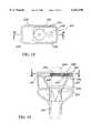
- FIG. 1is a perspective view of a preferred embodiment of the trocar of the present invention
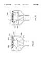
- FIG. 2is an axial cross-section view taken along lines 2--2 of FIG. 1, and illustrating a preferred embodiment of a valve housing and associated valve assembly;
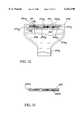
- FIG. 3is a top plan view taken along lines 3--3 of FIG. 2;
- FIG. 4is a radial cross-section view taken along lines 4--4 of FIG. 2;
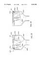
- FIG. 5is an axial cross-section view similar to FIG. 2 and illustrating an additional embodiment of a valve housing
- FIG. 6is a cross-section view similar to FIG. 2 and illustrating a small sized instrument and a medium sized instrument simultaneously operatively disposed through first and second valve sets of the trocar;
- FIG. 7is a radial cross-section view similar to FIG. 6 and illustrating a large instrument in the form of an obturator operatively disposed in the trocar;
- FIG. 8is a side view partially in section of the trocar illustrating a flapper valve having zero-closure characteristics in a further embodiment of the invention.
- FIG. 9is a top plan view taken along lines 9--9 of FIG. 8;
- FIG. 10is a perspective view illustrating an instrument inserted into a trocar comprising a further embodiment of the invention.
- FIG. 11is an exploded axial cross-section view of the trocar embodiment of FIG. 10 illustrating components including (from top to bottom) an end cap, a valve assembly, a partition structure, a valve housing, and a cannula;
- FIG. 12is an axial cross-section assembled view of the trocar illustrated in FIG. 11;
- FIG. 13is an axial cross-section view of the partition structure illustrated in FIG. 11;
- FIG. 14is a top plan view of the partition structure of FIG. 11;
- FIG. 15is an enlarged side elevation view of the partition structure of FIG. 11;
- FIG. 16is a top-plan view of a further embodiment of the invention having a seal housing with a rectangular configuration, and a floating septum disposed in a first position to accommodate a small instrument;
- FIG. 17is an axial cross-section view taken along lines 17--17 of FIG. 16;
- FIG. 18is a top-plan view similar to FIG. 16 and illustrating the floating system in a second position to accommodate a large instrument;
- FIG. 19is an axial cross-section view taken along lines 19--19 of FIG. 18;
- FIG. 20is an axial cross-section view similar to FIG. 17 and illustrating an embodiment with a pair of check valves in a first location and a closed state;
- FIG. 21is an axial cross-section view similar to FIG. 20 and showing one of the check valves moved to an open state by the small instrument;
- FIG. 22is an axial cross-section view of the embodiment of FIG. 20 showing the septum valves in a second location and the closed state;
- FIG. 23is an axial cross-section view similar to FIG. 21 and illustrating one of the check valves moved to the open state by the large instrument;
- FIG. 24is an axial cross-section view similar to FIG. 20 wherein the check valves are coupled as a single reciprocating valve disposed in a first position by the small instrument;
- FIG. 25is an axial cross-section view similar to FIG. 24 wherein the reciprocating valve is tripped to a second position by operation of the large instrument;
- FIG. 26is an axial cross-section view similar to FIG. 17 and illustrating an embodiment including multiple floating seal assemblies each including a septum valve and an associated zero-closure valve, the assemblies being illustrated in a first location;
- FIG. 27is an axial cross-section view similar to FIG. 25 and illustrating the floating valve assemblies in a second location;
- FIG. 28is an axial cross-section view of a further embodiment having a skirt flexibly connected between the septum and the housing in a septum chamber, with the valve assemblies illustrated in the first location;
- FIG. 29is an axial cross-section view similar to FIG. 27 and illustrating the valve assemblies in the second location;
- FIG. 30is an axial cross-section view of a further embodiment wherein the skirt is disposed in a primary chamber of the housing and coupled between the zero-closure valves and the walls of the housing, with the valve assemblies disposed in the first location;
- FIG. 32is a cross-section view similar to FIG. 17 of a further embodiment having multiple flotation structures.
- FIG. 33is a cross-section view of a septum with multiple cup seals in still a further embodiment of the invention.
- a multiport trocaris illustrated in FIG. 1 and designated generally by the reference numeral 10.
- the trocar 10is representative of any access device including a cannula 12 which is in the form of a hollow elongate cylinder having a distal end 14 and a proximal end 16. It is this cannula 12 which is sized and configured to extend across a body wall, such as an abdominal wall 15, into a body conduit or cavity, such as a blood vessel or an abdominal cavity 17.
- the cannula 12is preferably rigid, or semi-rigid and in preferred embodiments is formed of plastics or surgically compatible metals such as stainless steel.
- a passage 18 formed by the walls of the cannula 12extends along a central axis 21.
- valve housing 23also forms a significant part of the trocar 10.
- the valve housing 23includes a rigid housing portion 25 and an elastomeric housing portion 27 which together define a housing cavity 30.
- the rigid housing portion 25is preferably formed of plastic and disposed at the proximal end 16 in a fixed relationship with the cannula 12.
- a pair of finger tabs 32are formed as an integral part of the rigid housing portion 25 and provide means for engaging the trocar 10 and manipulating the cannula 12 into a preferred operative position.
- a collar 34is disposed distally of the tabs 32 where it is sized and configured to receive the proximal end 16 of the cannula 12, as best illustrated in FIG. 2.
- the elastomeric housing portion 27is preferably formed from a resilient material, and includes a cylindrical side wall 36 and an end wall 38 that are integral in a preferred embodiment.
- a resilient materialmay include natural rubber or, preferably, a non-rubber material such as nitrile, silicone, or a urethane.
- the side wall 36is preferably centered on the axis 21 of the cannula 12 while the end wall 38 is transverse, for example perpendicular, to the axis 21.
- the side wall 36 of the elastomeric housing portion 27is joined to and forms a seal with the rigid housing portion 25 at a circumferential joint 40.
- the cavity 30 formed by the valve housing 23is in fluid communication with the passage 18 of the cannula 12. Together this cavity 30 and passage 18 form a working channel 41 of the trocar 10. In the illustrated embodiment, this channel 41 extends from regions exterior of the trocar 10, through the end wall 38, into the housing cavity 30, and through the passage 18 and the distal end 14 of the cannula 12.
- the trocar 10functions as an access device so that instruments can be inserted through the seal housing 23 and the cannula 12 into the abdominal cavity 17.
- the trocar 10is disposed with the cannula 12 extending across the abdominal wall 15 and into the abdominal cavity 17.
- the abdominal cavity 17is typically pressurized or insufflated.
- this insufflation of the abdominal cavity 17is implemented by use of an insufflation tube 45 which is in fluid communication with the housing cavity 30 as well as the passage 18 of the cannula 12.
- various instrumentssuch as catheters, guide wires, graspers, staplers
- various instrumentscan be inserted through the working channel 41 of the trocar 10 to perform various functions within the abdominal cavity 17. It is important in such an operation, that the insufflation pressure be maintained both when the instruments are disposed within the working channel 41 of the trocar 10, as well as when the instruments are removed from the working channel 41.
- a valve assembly 46which is typically disposed within the housing cavity 30 or formed as part of the valve housing 23.
- the valve assembly 46 of the present inventionis sized and configured to accommodate a surgical instrument having substantially any diameter regardless of the size limitations of a single valve.
- a surgical instrumenthaving substantially any diameter regardless of the size limitations of a single valve.
- Such instrumentsare represented by a catheter 48, a retractor 49 and a obturator 50 best illustrated in FIGS. 6 and 7.
- the catheter 48, retractor 49 and obturator 50are sometimes referred to respectively as the small, medium and large instruments 48, 49, 50, and collectively as the instruments 48, 49 and 50.
- these instruments 48-50will vary widely in diameter.
- the small size instrument 48might include a guidewire or catheter up to two millimeters in diameter.
- the medium size instrument 49might include graspers or retractors between two and five millimeters in diameter.
- the large size instrument 50might include an obturator or laparoscope having diameters as small as five millimeters and as large as eleven or twelve millimeters.
- the valve assembly 46includes at least two and preferably three or four valve sets each adapted to receive a different range of instrument sizes, and collectively to accommodate the entire range of instrument sizes.
- the valve assembly 46includes a small valve set 52, a medium valve set 54 and a large valve set 56. These valve sets 52, 54 and 56 form, with the passage 18 of the cannula 12, three respective working channels 41a, 41b, and 41c.
- Each of the valve sets 52-56must have characteristics for forming a seal around the associated instrument 48-50 when it is operably disposed in the working channel 41, as well as characteristics for forming a seal across the working channel 41 when the associated instrument 48-50 is removed.
- both of these characteristicscan be provided by a single septum valve 58 which has an opening 59 small enough to close upon itself in the absence of the instrument 48, but large enough to accommodate instruments of up to about two millimeters in diameter.
- the large valve set 56is representative of the other valve sets in the valve assembly 46.
- This large valve set 56includes a large septum valve 61 as well as a large zero-closure valve 63.
- These valves 61 and 63can be of the type disclosed in applicant's copending application Ser. No. 08/051,609 filed on Apr. 23, 1993 and entitled "Seal Assembly for Access Device".
- the large septum valve 61is provided with a hole 65 which in its natural state has a diameter, such as about five millimeters. Forcing the instrument 50 with a diameter larger than about five millimeters through this hole 65 causes the valve 61 to expand so that it forms a tight seal with the outer surface of the instrument 50. However, when the instrument 50 is removed, the septum valve returns to its natural state leaving the hole 65 in an open state. Under these circumstances, the zero-closure valve 63 is of particular importance as it fully closes in the absence of the instrument 50. This insures that the working channel 41c through the large valve set 56 is fully closed when the instrument 50 is removed.
- the medium valve set 54is similar to the large valve set 56 in its function, however, it is generally smaller in size.
- the medium valve set 54includes a medium septum valve 67 and a medium zero-closure valve 70.
- the medium septum valve 67has a hole 71 which is sufficiently large to accommodate medium size instruments between about two millimeters and five millimeters, for example.
- This medium septum valve 67does not fully close as did the small septum valve 58, so the zero-closure valve 70 is required to seal the working channel 41b through the medium valve set 54 when the instrument 49 is removed.
- the lateral orientation of the respective septum valves 58, 67 and 61 in the end wall 38can be of particular importance.
- the three septum valves 58, 67 and 61are each centered on an associated longitudinal axis 72, 74 and 76.
- the zero-closure valves 70 and 63are centered on respective longitudinal axes 78 and 81.
- Each of the axes 72-76, associated with the respective septum valves 58, 67, and 61,is separated or off set from the axis 21 of the trocar 10 by a different distance.
- the axis 76 associated with the large septum 61is disposed closest to the axis 21. This orientation is preferred since a larger instrument, such as the obturator 50, requires a more vertical orientation with the trocar 10 due to the fact that its diameter more closely approaches that of the cannula 12.
- the septum valve 61is required to move only a small distance in order to achieve the more vertical orientation required by the large instrument 50.
- the medium sized instrumentscan pass through the cannula 12 at an angle so that the medium size instrument 49 does not require as vertical an orientation as the large instrument 50.
- the medium septum valve 67need not move as close to the axis 21 of the cannula 12 for operative disposition of the instrument 49.
- the axis 74 of the medium septum valve 67can be offset from the axis 21 of the cannula 12 a distance greater than that separating the axis 76 of the large septum valve 61 from the axis 21 of the cannula 12.
- its axis 72can be located at an even greater distance from the axis 21.
- small instrumentssuch as guidewires and the catheter 48, require very little vertical orientation, but they are often flexible so that no movement of the septum 58 is required for operative disposition of these small instruments.
- the septum valves 61 and 67be located so that they can move from their natural position, in the absence of the instruments 49, 50 to a more centered position, in the presence of the instruments 49, 50. This movement must occur without substantial deformation of the septum valve 67 and 61 so that the valve portions forming the respective holes 71 and 65 can form a suitable seal with the outer surface of the instruments 49, 50.
- the movement of the septum valves 61 and 67is referred to herein as flotation, which generally includes two types of movement.
- the first type of flotationis associated with valve selection, while the second type of flotation is associated with seal maintenance during instrument manipulation. More specifically, the first type of flotation associated with valve selection provides for movement of the valves 61 and 67 between a first position wherein the valve 61 is operatively disposed, and a second position wherein the valve 67 is operatively disposed.
- instrument manipulationcan give rise to a cat eye effect where proper seal formation is inhibited by movement of the instrument.
- Flotation of the valves 61 and 67facilitate maintenance of the associated seals even during instrument manipulation. In a preferred embodiment, these two types of flotation are independent of each other.
- the end wall 38is formed of an elastomeric material thereby permitting the septum valves 58, 67 and 61 to move laterally within the end wall 38.
- the side wall 36 of the housing portion 27is also formed of an elastomeric material and is easily deflected laterally. This movement of the side wall 36 carries the entire end wall 38 to a desired position without deformation of the associated septum valve 58, 67 and 61.
- the septum valves 58, 67 and 61have a floating relationship with the cannula 12 which permits them to move laterally while still maintaining their properties for forming a seal with the outer surface of the associated instrument 48-50.
- This lateral deflection of the side wall 36is illustrated in both FIGS. 6 and 7 for the respective instruments 49 and 50.
- the septum valves 58, 67 and 61are formed in the end wall 38 of the elastomeric housing portion 27. It will be apparent, however, that these valve 58, 67 and 61 can be formed generally in any wall which is transverse to the axis 21 of the cannula 12. The resulting valve wall can be included within the housing cavity 30 or can form part of the valve housing 23. Nevertheless, it is generally preferred that the septum valves 58, 67, and 61 be formed in the proximal-most wall, such as the end wall 38, of the valve housing 23.
- the location of the zero-closure valve 70 and 63can also be critical in a particular embodiment. It is not required that the axes 78 and 81 associated with the zero-closure valves 70 and 63 respectively, be aligned with the axes 74 and 76 of the associated septum valves 67 and 61. This alignment of valves within a valve set, which is characteristic of the prior art, is not required by the present invention. Rather the location of the zero-closure valves 70 and 63 is generally dependent on two different considerations.
- the zero-closure valve 70must be positioned such that the instrument 49 passing through the associated septum valve 67 also passes through a zero-closure valve 70.
- the zero-closure valve 63must be positioned so that the instrument 50, passing through the associated septum valve 61 also passes through the zero-closure valve 63. As can be seen from FIG. 3, this requirement is not particularly stringent so that the septum valves 67 and 61 can be located relatively close to the central axis 21 while the associated zero-closure valve 70 and 63 are located relatively far from the central axis 21.
- the second consideration for location of the zero-closure valves 70 and 63is based on their proximity to each other. It is important that when the medium instrument 49 is positioned within the medium valve set 54, that it not interfere with the ability of the large zero-closure valve 63 to seal the working channel 41c. This generally requires that the medium zero-closure valve 70 be separated from the large zero-closure valve 63 a distance sufficient to prevent deformation of the large zero-closure valve 63.
- this interference with a non-associated zero-closure valve 63is of perhaps greatest concern with respect to the medium valve set 54.
- the medium instrument 49will typically have a more angled disposition within the housing cavity 30 than the large instrument 50.
- the large zero-closure valve 63will typically extend further into the housing cavity 30, as illustrated in FIG. 2, making it more susceptible to interference from the medium instrument 49.
- Each of these zero-closure valves 70 and 63includes respectively, a cylindrical side wall 82 and 83, and a closure structure defined by walls 85 and 87. These walls 85, 87 define lateral recesses 89, 92 as they converge to lines 94, 96, respectively, which form the cross seal associated with this type of zero-closure valve. These lines 94 and 96 are best illustrated in FIG. 4. The configuration of the walls 85, 87 and the associated recesses 89, 92 and lines 94, 96 are described in greater detail in applicant's copending application Ser. No. 08/051,609.
- this configuration of the zero-closure valves 70 and 63facilitates a structure wherein one of the valves, such as the valve 70, can be provided with a side wall, such as the side wall 82, which is shorter than the side wall, for example the side 83, associated with the other zero-closure valve, such as the valve 70. Then, a recess or indentation 98, can be formed in the other side wall, such as the side wall 83. It will be apparent that this solution will be equally appropriate with a longer side wall 82 in the medium zero-closure valve 70, and an appropriate indentation, such as the indentation 98, in that side wall 82.
- Another way of accommodating the close proximity of the zero-closure valves 70 and 63is to orient the associated seal lines 94 and 96 so that neither is disposed along a line interconnecting the axes 78 and 81 of the respective valve 70 and 63. Since these seal lines 94 and 96 extend to the greatest diameter of the associated walls 85 and 87 they are most susceptible to interference by an instrument extending through the opposite valve set 54, 56. By orienting these lines 94 and 96, as illustrated in FIG. 4, the natural recesses 89 and 92 formed between lines 94, 96 are automatically faced toward the opposing axis 78, 81.
- the zero-closure valve 63extends beyond the joint 40 between the rigid housing portion 25 and the elastomeric housing portion 27.
- the elastomeric housing portion 27return to its natural state wherein its side wall 36 is coaxial with the central axis 21. This return to the natural state is facilitated in a preferred embodiment wherein the housing portion 27 is provided with a plurality of ribs 101 which extend radially and longitudinally of the side wall 36 within the housing cavity 30.
- the entire elastomeric housing portion 27(including the ribs 101) and the entire valve assembly 46 (including the septum valves 58, 67, 61 and the zero-closure valves 70, 63) are formed as an integral structure from an elastomeric or resilient material such as latex.
- the obturator 50 of the present inventionis typical of those of the past in that it includes a handle 102 and a shaft 103 having a sharp distal tip 104.
- This obturator 50is designed for axial insertion through the valve housing 23 and into the cannula 12 as illustrated by the dotted line position in FIG. 7. Further axial movement into the cannula 12 brings the obturator 50 to an operative position where the sharp distal tip 104 of the obturator 50 extends beyond the distal end 14 of the cannula 12.
- This operative positionis shown by the solid line position of the obturator 50 in FIG. 7.
- this axial pressurewas directed through the handle and applied against the proximal end of the valve housing.
- this additional pressure on the proximal end of the housing 23would only seek to compress the elastomeric housing portion 27. This would not only make it difficult to insure the operative disposition of the sharp tip 104 beyond the cannula 12, but also could damage the elastomeric housing portion 27.
- the obturator 50is provided with an enlargement or projection 105 which is fixed to the outer surface of the shaft 95.
- the projection 105takes the form of an annular flange which extends radially outwardly from the outer surface of the shaft 103.
- this projection 105moves through the housing cavity 30 into engagement with the proximal end 16 of the cannula 12 which finctions as a stop for the projection 105. Since the projection 105 is larger than the inside diameter of the cannula 12 in this embodiment, further axial movement of the obturator 50 is prevented.
- the distal tip 104 of the shaft 103extends beyond the distal end 14 of the cannula 12, but the handle 102 does not axially compress the elastomeric housing portion 27.
- the projection 105can be positioned along the shaft 102 at any location where it can engage part of the rigid housing portion 25, such as the collar 34, or the proximal end 16 of the cannula 12.
- the trocar 10aincludes a cannula 12a, having a distal end 14a and a proximal end 16a, and a valve housing 23a which partially defines a housing cavity 30a.
- the trocar 10aalso includes the insufflation tube 45a and is illustrated in combination with a retractor 49a which is representative of various surgical instruments. Both the cannula 12a and the valve housing 23a are aligned along the axis 21a of the trocar 10a.
- the housing cavity 30ais also partially defined by an end cap 121 which is movable transverse to the axis 21a at the proximal end 16a.
- the end cap 121includes access ports 123-127 which provide access for small, medium and large diameter instruments, respectively, into a working channel 41a of the trocar 10a.
- the trocar 10aalso includes a valve assembly 46a and a partition structure 130.
- Another feature associated with this embodimentis the modularity of construction which provides for a quick disconnect between the cannula 12a and the remainder of the trocar including the valve housing 23a and the valve assembly 46a.
- This quick disconnect in the illustrated embodimenttakes the form of a bayonet connection including tabs 132 and associated slots 134.
- the cannula 12a of this embodimentextends from the distal end 14a to an enlarged proximal portion 136 having a proximal facing end surface 138.
- the valve housing 23ahas a lower skirt 141 which is sized to receive the proximal portions 136 of the cannula 12a. It is this skirt 141 which defines the slots 134 of the bayonet connection. Extending in the opposite direction from the skirt 141 is a sidewall 143 which extends proximally to an end surface 145. It is the side wall 143 together with the end cap 121 which define the housing cavity 30a.
- annular flange 147extends inwardly providing a proximal facing surface 152 and a distal facing surface 154.
- An annular projection 156which extends from the flange 147 toward the skirt 141, will be discussed in greater detail below.
- the partition structure 130includes a proximal end wall 161 having a proximal surface 163. Extending downwardly in FIG. 11 from the end wall 161, is a partition 165 which has a particular configuration discussed in greater detail below. The partition 165 extends to a bottom surface 167. Extending upwardly from the surface 163 of the end wall 161 are a plurality of buttons 170 which facilitate a snap fit relationship between the partition structure 130 and the end cap 121.
- the end cap 121has a generally planar configuration defined by a wall 190 having a distally facing surface 192. Extending upwardly from the wall 190 are a plurality of cylinders 194 and 196 which aid in aligning the instruments and protecting the septum valve formed in the end wall 172 of the valve assembly 46a. Extending downwardly in FIG. 11 from the end wall 190 is an annulus 198 which functions to prevent deformation of the zero-closure valve. Also extending downwardly from the end wall 190 are a plurality of male components 197 which register with the female projections 170 in a snap fit relationship.
- FIG. 11These various components of FIG. 11 are also illustrated in the assembled view of FIG. 12. Of particular interest in this view are the relationships among the flange 185 of the valve assembly 46a, the flange 147 of the housing 23a, and the surface 138 of the cannula 12a. In this construction, the flange 185 is sandwiched between the surface 138 of the cannula 12a and the surface 154 of the flange 147. It is this combination which automatically forms a seal between the valve assembly 46a, the housing 23a and the cannula 12a. The seal is enhanced by the projection 156 on the flange 147 which increases the sealing relationship between the flange 147 and the elastomneric flange 185.
- a subassemblycan be formed between the end cap 121, the valve assembly 46a and the partition structure 130.
- the partition structure 130is inserted through the opening at the bottom of the valve assembly 46a where the partition 165 extends around the zero-closure valves of the assembly.
- the proximal end wall 161 of the structure 130is brought into contact with the end wall 172 of the valve assembly 46a. With the projections 170 of the structure 130 extending through concentric holes in the end wall 172.
- the end cap 121With the partition structure 130 operatively positioned within the valve assembly 46a, the end cap 121 can be moved into position over the top of the valve structure 46a. In this step, the projections 197 of the end cap 121 extend into the buttons 170 associated with the partition structure 130 preferably in a snap fit relationship. This snap fit completes the subassembly by maintaining the end wall 190 of the end cap 121, the end wall 172 of the valve assembly 46a, and the end wall 161 of the partition structure 130 in a generally fixed relationship.
- the resulting top view of the subassemblyis best illustrated in FIG. 14. In this view, the valve sets are not shown in detail, but nevertheless are represented by their reference numerals 52a, 54a and 56a.
- the distally facing surface 181 of the valve assembly 46ais also brought into contact with the proximal facing surface 152 of the housing 23a.
- the interlocking relationship of the flange 147 and 185is assisted by the projection 156 on the annular flange 147 and a similar projection on the flange 185.
- the cannula 12acan be introduced distally into the channel defined by the skirt 141. This brings the proximal surface 138 of the cannula 12a into abutting relationship with the distally facing surface 187 of the valve assembly 46a. It also sandwiches the elastomeric flange 185 between the surface 154 of the flange 147 and the surface 138 of the cannula 12a. This not only maintains the elastomeric flange 185 in a fixed relationship with the housing 23a and cannula 12a, but also enhances formation of seals between these adjacent elements. As previously discussed, the cannula 12a can be held in its operative position by a quick disconnect structure such as the bayonet fitting formed between the tabs 132 and slots 134.
- a quick disconnect structuresuch as the bayonet fitting formed between the tabs 132 and slots 134.
- floating of the seal sets 54a and 56ais facilitated by permitting the end cap 121 to move transverse to the axis 21a in sliding engagement with the side wall 143 of the housing 23a. While this floating movement of the end cap 121 could be accomplished in an enlarged recess, as taught by Ritchart et al, the size of the housing 23a can be reduced if the end cap 121 is permitted to define the largest diameter of the trocar 10 at its proximal end. In this case, the outside diameter of the side wall 143 of the housing 23a does not exceed the diameter of the end cap 121.
- the medium seal set 54a(including the septum valve 67a and zero-closure valve 70a) and the large seal set (including the septum valve 61 a and zero-closure valve 63a may also benefit from additional isolation.
- an instrumentwill be inserted through one of the seal sets, such as the set 54a, where the associated septum valve forms a seal with the instrument.
- the zero-closure valve 70awill be open and non-sealing as long as the instrument is in place. The concern at this point is with the operation of the zero-closure valve 63a associated with the other valve set. If the instrument is allowed to tilt or is otherwise brought into contact with the zero-closure valve 63a, associated with the other valve set 56a, that valve 63a can be deformed resulting in leaking of the insufflation gas.
- valvessuch as the zero-closure valves 70a and 63a, can be provided in any form associated with the prior art. Double duck bill valves such as those illustrated in FIGS. 1-7 are particularly appropriate for this concept. However, a separate flapper valve, such as those designated by the reference numerals 107 and 109 in FIGS. 8 and 9 can be provided for the respective valve sets 54 and 56.
- the end cap 121can be formed in sliding engagement with the housing 23a. This embodiment is enhanced by the small size of the housing 23a which is not greater than the diameter of the end cap 121.
- the valve assembly 46acan be stretched to maintain the end cap 121 in sliding engagement with the housing 23a.
- the annulus 98can be formed to uniformly limit the lateral displacement of the end cap 121 relative to the housing 23a.
- the partition 165further protects the zero-closure valves 63a and 70a from interference due to operation of an adjacent valve set.
- the modular conceptpermits the cannula 12a to be separated from the housing 23a while at the same time providing a quick disconnect fitting which will function to enhance the seal between the valve assembly 46a and the housing 23a.
- FIG. 16A further embodiment of the invention is illustrated in the top-plan view of FIG. 16 and the associated cross-sectional view of FIG. 17, where a trocar is designated by the reference numeral 208.
- This embodiment of the trocar 208includes a cannula 210 having a distal end 212 and a proximal end 214.
- a valve housing 216is disposed at the proximal end 214 and defines a working channel 218 with the cannula 210.
- the valve housing 216 in this embodimenthas rigid walls 221 which in radial cross-section have the shape of a polygon, such as a square or rectangle, as best illustrated in FIG. 16.
- the rectangle in this embodimenthas a long-side 223 extending in one direction, and a short side 225 extending in a second direction generally perpendicular to first direction.
- the septum valves 230 and 232are also adapted to receive the instrument 236. However, by comparison, when the instrument 236 is not present, the septum valves 230 and 232 do not form a seal. It is only when the instrument 236 is present that the septum valves 230 and 232 form a seal with the cylindrical outer surface of the instrument 236.
- the septum valves 230 and 232are of different sizes and are adapted to accommodate different diameters of instruments.
- the septum 232is of a smaller size and, therefore, adapted to accommodate a small instrument 236, while the septum 230 is of a larger size and, therefore, adapted to accommodate a larger instrument 236'.
- the septum 234can be mounted between an end wall 243 of the housing 216, and a second partition 245 which also extends between the walls 221. These walls 243 and 245 form portions of the housing 216 which define a cavity 247 that is flat in configuration and generally perpendicular to the axis of the cannula 210. The septum 234 is disposed in this cavity 247 and, importantly, is free to float between the end wall 243 and the partition 245.
- a leakage conditioncan develop through the unused septum.
- a positive air pressureexists within the cannula 210, it can be appreciated that this positive pressure is transferred to the septum 234 when the zero-closure valve 227 is open.
- the septum 234may form a seal with the instrument 236 to prevent escape of this pressurized air
- the other septum seal 230would typically be in an open state thereby permitting the pressurized air to escape through the septum 234.
- cup seals 250 and 251can be formed around the septums 230 and 232, respectively, so that each one is isolated from the pressurized air when it is not in its operative position.
- the cup seal 250isolates the septum 230 from the pressurized fluid.
- the cup seal 252isolates the septum seal valve 232 from the pressurized fluid, as illustrated in FIG. 19, by permitting fluid communication with only one septum at a time with the cannula.
- the cup seals 250b and 251b associated with the septum valves 230b and 232b, respectively,can be augmented by a pair of check valves 252 and 254, respectively.
- the check valve 252is pivotal on the septum 234b and includes a blocking element 256 which is larger than the hole 230b in the septum 234b.
- the check valve 254is pivotal on the septum 234b and includes a blocking element 258 which is larger than the hole 232b in the septum 234b.
- the septum 234bis initially moved or floated to the second location, as illustrated in FIG. 22. Then the larger instrument 236b' can be inserted, as illustrated in FIG. 23, opening the check valve 252 to gain access to the zero-closure valve 227b. As pressurized fluid is exposed to the septum 234b, it is maintained within the housing 216b by a seal formed between the septum valve 230b and the instrument 236b'. Blow-back through the smaller septum valve 232b is prevented by the check valve 254, which forms a seal with the blocking element 258.
- FIGS. 24 and 25elements of similar structure are designated by the same reference numeral followed by the lower case letter "c".
- This embodimentdiffers from that of FIG. 20 in that the check valves 252c and 254c do not operate independently, but rather function as a toggle or reciprocating valve 261.
- the reciprocating valve 261pivots on the septum 234c at a fulcrum 263.
- the check valve 252chas a lever arm 265 which carries the blocking element 256b in a pivotal relationship with the fulcrum 263.
- a lever arm 267carries the blocking element 258c in a pivotal relationship with the fulcrum 263.
- a connecting arm 269can be provided between the blocking elements 256c and 258c.
- insertion of the instrument 236cnot only opens the septum valve 232c, but it pivots the reciprocating valve 261 about the fulcrum 263, automatically moving the element 257c into a blocking relationship with the septum valve 230c, as illustrated in FIG. 24.
- insertion of the larger instrument 236c' through the septum valve 230cpivots the reciprocating valve 261 about the fulcrum 263 automatically moving the element 258c into a blocking relationship with the septum valve 232c.
- check valves 252 and 254operate independently.
- the open or closed state of the check valve 252is not dependent upon the open or closed state of the check valve 254.
- the reciprocating valve 261 of FIG. 24operates such that the position of the blocking element 256c is dependent upon the position of the blocking element 258c. For example, as the blocking element 258c is moved to the open position by the instrument 236c, as illustrated in FIG. 24, the blocking element 257c is simultaneously moved to the closed position. Similarly, when the blocking element 257c is moved to the open position by the instrument 236c', as illustrated in FIG. 25, the blocking element 258c is simultaneously moved to the closed position.
- the check valves 252 and 254 in FIG. 20are individually biased to the closed position. This may not be the case with the reciprocating valve 261 which can rely upon the force of instrument insertion to move the respective blocking members 256c and 258c to their closed positions.
- the reciprocating valve 261can include an over-center device so that the blocking elements 257c and 258c are alternatively biased to their closed positions. Nevertheless, the blocking elements 257c and 258c will tend to move in unison, that is, with one of the blocking elements, such as the element 257c, moving toward the closed position, and the other of the blocking elements, such as the element 258c, moving toward the open position. Notwithstanding this tendency to move in unison, the blocking elements 257c and 258c may not have a rigid, fixed relationship. In such an embodiment, the connecting arm 269 may have some elastic characteristics permitting slight relative movement between the blocking elements 257c and 258c.
- valve 261could be toggled, not by instrument insertion, but rather by movement of the septum 234c between its first and second locations. In such an embodiment, lateral movement of the septum would toggle the valve 261 to open one of the septum valves 230c and 232c, and close the other of the septum valves 232c and 230c, respectively.
- this embodimentincludes the cannula 210d, the valve housing 216d with walls 221d, the end wall 243d, and the partition 245d.
- the septum 234dis free to move to accommodate both types of flotation, that associated with septum selection, as well as that associated with instrument manipulation.
- This embodimentalso includes the large septum valve 230d and the smaller septum valve 232d.
- each of these septum valvesis combined with an associated zero-closure valve 272 and 274 to form separate valve assemblies 276 and 278.
- Each of the zero-closure valves 272 and 274is coupled to the septum 234d, and therefore moves with the septum 234d as it floats within the cavity 247d.
- each septum valve, and its associated zero-closure valveis alternatively moved to an operative position in general alignment with the cannula 210d.
- the valve assembly 278, including the septum valve 232d and the zero-closure valve 274are in an operative position generally aligned with the cannula 210d.
- the second valve assembly 276, including the septum valve 230d and the associated zero-closure valve 272are moved to the operative position in general alignment with the cannula 210d.
- blow-backis not a significant problem.
- an instrumentis inserted into one of the valve assemblies, such as the assembly 278, pressurized air is not free to escape through the other septum valve, such as the valve 230d, because it has its own zero-closure valve, in this instance the valve 272, to prevent blow-back.
- FIG. 28Another alternative is illustrated in FIG. 28 wherein elements of similar structure are designated by the same reference numeral followed by the lower case letter "e".
- a skirt 281can be connected between the perimeter of the septum 234e and the walls 221e, forming the valve housing 216e. With this configuration, pressurized air that might extend beyond the partition 243e into the cavity 247e would be maintained within the trocar 208e by the skirt 281. With the skirt 281 having impermeable but flexible characteristics, this pressurized air is retained regardless of the position of the septum 234e.
- the pressurized airis maintained within the housing 216e, whether the septum 234e is in the first location as illustrated in FIG. 28, or the second location as illustrated in FIG. 29.
- the skirt 261therefore, provides the same sealing function as either, or both, of the sealing portions of the cup seals 250 and 252 of FIGS. 17 and 19.
- FIGS. 30 and 31Another skirt embodiment is illustrated in FIGS. 30 and 31 where elements of structure similar to that previously discussed are designated with the same reference numeral followed by the lower case letter "f".
- this embodimentincludes the cannula 210f, the valve housing 216f with walls 221f, as well as the end wall 243f and partition 245f which form the cavity 247f.
- the valve assemblies 276f and 278fare free to float with the septum 234f as it moves within the cavity 247f.
- a skirt 283is provided and attached to the perimeter of each of the zero-closure valves 272f and 274f. From this location, the skirt 283 extends outwardly to engage the walls 221f distally of the partition 245f. In such an embodiment, air pressure within the cannula 210f is maintained distally of the cavity 247f, not only by the zero-closure valves 274f and 276f, but also by the skirt 283. In this embodiment, the cavity 247f and the septum 234f are never exposed to the pressurized air. This is true regardless of the position of the septum 234f. For example, in FIG. 30, the cavity 247f is isolated from pressurized air with the septum 234f in the first location. When the septum 234f is moved to the second location, as illustrated in FIG. 30, the cavity 247f remains isolated from the pressurized air. As in the previous embodiment, the skirt 283 is preferably both flexible and impermeable.
- FIG. 32A further embodiment of the invention is illustrated in FIG. 32 wherein elements similar to those previously discussed are designated by the same reference numeral followed by the lower case letter "g".
- this embodimentincludes the cannula 210g and the valve housing 216g, together with the end wall 243g and partition 245g which define the septum cavity 247g.
- the septum 234gfloats within the cavity 247g and includes the septum valves 230g and 232g.
- flotation of the septum 234g within the cavity 247gaccommodates both valve selection and instrument manipulation.
- the second function, instrument manipulationis further accommodated by a structure which floats the septum valves 230g and 232g within the septum 234g.
- flotation of the septum 234g within the cavity 247gprimarily accommodates valve selection, while flotation of the septum valves 230g and 232g within the septum 234g primarily accommodates instrument manipulation.
- the septum 234gis formed with a rigid plate 290 that can be insert-molded to a resilient structure 292.
- the rigid plate 290is provided with apertures 294 and 296, which provide access to the associated septum valves 232g and 230g.
- Both the rigid plate 290 and the resilient structure 292have a generally planer configuration providing the septum 234g with a relatively low profile which is free to float within the cavity 247g.
- the resilient structure 292 in this embodimentincludes a perimeter block 298, which is fixed to the rigid plate 290 around the septum valves 230g and 232g. At least one accordion pleat 301 surrounds the septum valve 230g. A similar pleat 303 surrounds the septum valve 232g. These accordion pleats 301 and 303 provide the associated septum valves 230g and 232g with additional flotation characteristics which enable the valves to move relative to the other elements of the septum 234g. As a result, the septum valves 230g and 232g are free to float, not only with the septum 234g, but also within the septum 234g.
- each structurecan be varied to adjust the flotation characteristics of one type of flotation relative to the other type of flotation.
- the accordion pleats 301 and 303can provide a higher degree of flotation than that associated with the septum 234g moving within the cavity 247g. This insures that the septum valves 230g and 232g have a high degree of flotation accommodating even small degrees of instrument manipulation. This higher degree of flotation is particularly advantageous in avoiding the "cat eye effect" resulting from instrument manipulation. Flotation of the septum 234g within the cavity 247g is then primarily directed to septum selection which generally requires a higher degree of force to overcome friction associated with the cup seal 250g.
- FIG. 33Another septum having these dual flotation characteristics is illustrated in FIG. 33 wherein elements similar to those previously discussed are designated by the same reference numeral followed by the lower case letter "h".
- the septum 234his provided with the cup seal 250h, which floats in a sealing relationship with the inner surface of the partition 245g.
- the rigid plate 290 of FIG. 32is replaced by a second cup seal 305, which floats in a sealing relationship with the inner surface of the end wall 234g.
- the cup seals 250h and 305can be formed integral with the perimeter block 298, but the second valves 230h and 232h remain free to float within the septum 234h.
Landscapes
- Health & Medical Sciences (AREA)
- Surgery (AREA)
- Life Sciences & Earth Sciences (AREA)
- Biomedical Technology (AREA)
- Nuclear Medicine, Radiotherapy & Molecular Imaging (AREA)
- Engineering & Computer Science (AREA)
- Pathology (AREA)
- Heart & Thoracic Surgery (AREA)
- Medical Informatics (AREA)
- Molecular Biology (AREA)
- Animal Behavior & Ethology (AREA)
- General Health & Medical Sciences (AREA)
- Public Health (AREA)
- Veterinary Medicine (AREA)
- Surgical Instruments (AREA)
Abstract
Description
Claims (39)
Priority Applications (1)
| Application Number | Priority Date | Filing Date | Title |
|---|---|---|---|
| US09/191,759US6162196A (en) | 1994-07-14 | 1998-11-12 | Multiport access device |
Applications Claiming Priority (3)
| Application Number | Priority Date | Filing Date | Title |
|---|---|---|---|
| US08/275,620US5569205A (en) | 1994-07-14 | 1994-07-14 | Multiport trocar |
| US08/793,494US6217555B1 (en) | 1994-07-14 | 1995-05-19 | Multiport trocar |
| US09/191,759US6162196A (en) | 1994-07-14 | 1998-11-12 | Multiport access device |
Related Parent Applications (1)
| Application Number | Title | Priority Date | Filing Date |
|---|---|---|---|
| US08/793,494Continuation-In-PartUS6217555B1 (en) | 1994-07-14 | 1995-05-19 | Multiport trocar |
Publications (1)
| Publication Number | Publication Date |
|---|---|
| US6162196Atrue US6162196A (en) | 2000-12-19 |
Family
ID=26957506
Family Applications (1)
| Application Number | Title | Priority Date | Filing Date |
|---|---|---|---|
| US09/191,759Expired - LifetimeUS6162196A (en) | 1994-07-14 | 1998-11-12 | Multiport access device |
Country Status (1)
| Country | Link |
|---|---|
| US (1) | US6162196A (en) |
Cited By (185)
| Publication number | Priority date | Publication date | Assignee | Title |
|---|---|---|---|---|
| US6458077B1 (en)* | 1999-07-29 | 2002-10-01 | Richard Wolf Gmbh | Medical instrument, in particular a rectoscope |
| US20040068232A1 (en)* | 2002-10-04 | 2004-04-08 | Hart Charles C. | Surgical access device with pendent valve |
| US20040204671A1 (en)* | 2003-04-08 | 2004-10-14 | Stubbs Jack B. | Continuous gas flow trocar assembly |
| US6811546B1 (en) | 2000-08-25 | 2004-11-02 | Origin Medsystems, Inc. | Endoscopic surgical access port and method |
| US20050004512A1 (en)* | 2003-04-08 | 2005-01-06 | Campbell Michael J. | Pneumoseal trocar arrangement |
| US20050015043A1 (en)* | 2003-04-08 | 2005-01-20 | Stubbs Jack B. | Gas flow trocar arrangement |
| US20050070851A1 (en)* | 2003-09-30 | 2005-03-31 | Thompson Brian J. | Trocar housing/stop-cock assembly |
| US20050197620A1 (en)* | 2004-03-02 | 2005-09-08 | Fung-Chao Tu | Safety trocar device |
| US20060071432A1 (en)* | 2004-09-29 | 2006-04-06 | Staudner Rupert A | Seal for trocar |
| US7037303B2 (en) | 2001-07-06 | 2006-05-02 | Opticon Medical, Inc. | Urinary flow control valve |
| US7094218B2 (en) | 2004-03-18 | 2006-08-22 | C. R. Bard, Inc. | Valved catheter |
| US20060212063A1 (en)* | 2005-03-18 | 2006-09-21 | Wilk Patent, Llc | Surgical device and associated trans-organ surgical method |
| US20060217666A1 (en)* | 2005-03-28 | 2006-09-28 | Thomas Wenchell | Introducer seal assembly |
| US20070088275A1 (en)* | 2003-04-08 | 2007-04-19 | Ralph Stearns | Trocar assembly with pneumatic sealing |
| US7300399B2 (en) | 1998-12-01 | 2007-11-27 | Atropos Limited | Surgical device for retracting and/or sealing an incision |
| FR2904210A1 (en)* | 2006-07-31 | 2008-02-01 | Jean Pierre Cohen | Proctoscopy trocar for e.g. therapeutic application, has hollow body receiving transversal part connected to body and acting as sealing around passages, where body has inflation pipe arranged on outer wall |
| US20090005738A1 (en)* | 2007-06-29 | 2009-01-01 | Ethicon Endo-Surgery | Insertion device with floating housing and method of use |
| CN100457055C (en)* | 2003-09-30 | 2009-02-04 | 伊西康内外科公司 | Improved trocar housing/piston valve assembly |
| DE102007040358A1 (en)* | 2007-08-27 | 2009-03-05 | Technische Universität München | Trocar tube, trocar, obturator or rectoscope for transluminal endoscopic surgery over natural orifices |
| US7540839B2 (en) | 1999-10-14 | 2009-06-02 | Atropos Limited | Wound retractor |
| US7559893B2 (en) | 1998-12-01 | 2009-07-14 | Atropos Limited | Wound retractor device |
| US20090182340A1 (en)* | 2007-09-13 | 2009-07-16 | Julian Nikolchev | Safety needle for accessing the interior of a hip joint |
| US20090192465A1 (en)* | 2008-01-30 | 2009-07-30 | Tyco Healthcare Group Lp | Access assembly with spherical valve |
| ES2324267A1 (en)* | 2007-12-20 | 2009-08-03 | Eduardo Sanchez De Badajoz Chamorro | Surgical device for laparoscopy and endoscopy |
| US20090209915A1 (en)* | 2008-02-14 | 2009-08-20 | Tyco Healthcare Group Lp | Flip-top design cannula |
| US7578803B2 (en) | 2004-03-18 | 2009-08-25 | C. R. Bard, Inc. | Multifunction adaptor for an open-ended catheter |
| US20090221966A1 (en)* | 2008-03-03 | 2009-09-03 | Tyco Helathcare Group Lp | Single port device with multi-lumen cap |
| US7637893B2 (en) | 2004-04-30 | 2009-12-29 | C. R. Bard, Inc. | Valved sheath introducer for venous cannulation |
| EP2138116A1 (en)* | 2008-06-27 | 2009-12-30 | Tyco Healthcare Group, LP | Trocar assembly with radially moveable housing |
| US20100010445A1 (en)* | 2004-03-18 | 2010-01-14 | C. R. Bard, Inc. | Connector system for a proximally trimmable catheter |
| EP2168509A1 (en)* | 2008-09-30 | 2010-03-31 | Ethicon Endo-Surgery, Inc. | Variable surgical access device |
| US20100081881A1 (en)* | 2008-09-30 | 2010-04-01 | Ethicon Endo-Surgery, Inc. | Surgical Access Device with Protective Element |
| EP2168511A3 (en)* | 2008-09-30 | 2010-07-14 | Ethicon Endo-Surgery, Inc. | Surgical access device |
| US20100194060A1 (en)* | 2008-11-03 | 2010-08-05 | Erblan Surgical, Inc. | Universal closure and method of lubrication |
| CN101822554A (en)* | 2009-03-06 | 2010-09-08 | 伊西康内外科公司 | The surgical access devices and the method that in predefined paths, provide sealing to move |
| EP2229897A1 (en) | 2009-03-18 | 2010-09-22 | Tyco Healthcare Group LP | Surgical portal apparatus including movable housing |
| US20100280437A1 (en)* | 2007-12-27 | 2010-11-04 | University Of South Florida | Multichannel trocar |
| US7842013B2 (en) | 2004-01-23 | 2010-11-30 | Genico, Inc. | Trocar and cannula assembly having conical valve and related methods |
| US20100312066A1 (en)* | 2009-06-05 | 2010-12-09 | Ethicon Endo-Surgery, Inc. | Inflatable retractor with insufflation |
| US20100312189A1 (en)* | 2009-06-05 | 2010-12-09 | Ethicon Endo-Surgery, Inc. | Flexible cannula devices and methods |
| US20100312064A1 (en)* | 2009-06-05 | 2010-12-09 | Ethicon Endo-Surgery, Inc. | Retractor with integrated wound closure |
| US7854731B2 (en) | 2004-03-18 | 2010-12-21 | C. R. Bard, Inc. | Valved catheter |
| US7867164B2 (en) | 1999-10-14 | 2011-01-11 | Atropos Limited | Wound retractor system |
| US7875019B2 (en) | 2005-06-20 | 2011-01-25 | C. R. Bard, Inc. | Connection system for multi-lumen catheter |
| EP2305148A1 (en) | 2002-12-02 | 2011-04-06 | Applied Medical Resources Corporation | Universal access seal |
| US20110082346A1 (en)* | 2009-10-02 | 2011-04-07 | Tyco Healthcare Group Lp | Single port device including selectively closeable openings |
| US20110112370A1 (en)* | 2005-06-24 | 2011-05-12 | Mimi Nguyen | Minimally invasive surgical stabilization devices and methods |
| US20110124967A1 (en)* | 2009-11-20 | 2011-05-26 | Ethicon Endo-Surgery, Inc. | Discrete flexion head for single port device |
| US20110124970A1 (en)* | 2009-11-24 | 2011-05-26 | Tyco Healthcare Group Lp | Foam port device having closed-end lumens |
| US20110144440A1 (en)* | 2009-12-11 | 2011-06-16 | Ethicon Endo-Surgery, Inc. | Methods and devices for accessing a body cavity |
| US20110144442A1 (en)* | 2009-12-11 | 2011-06-16 | Ethicon Endo-Surgery, Inc. | Methods and Devices for Providing Access into a Body Cavity |
| US20110144444A1 (en)* | 2009-12-11 | 2011-06-16 | Ethicon Endo-Surgery, Inc. | Methods and devices for providing access through tissue to a surgical site |
| US20110144590A1 (en)* | 2009-12-11 | 2011-06-16 | Ethicon Endo-Surgery, Inc. | Methods and devices for providing access through tissue to a surgical site |
| US20110144447A1 (en)* | 2009-12-11 | 2011-06-16 | Ethicon Endo-Surgery, Inc. | Methods and devices for providing access through tissue to a surgical site |
| US20110144437A1 (en)* | 2009-12-11 | 2011-06-16 | Ethicon Endo-Surgery, Inc. | Methods and devices for providing surgical access through tissue to a surgical site |
| US20110144443A1 (en)* | 2009-12-11 | 2011-06-16 | Ethicon Endo-Surgery, Inc. | Inverted conical expandable retractor with coil spring |
| US20110144449A1 (en)* | 2009-12-11 | 2011-06-16 | Ethicon Endo-Surgery, Inc. | Methods and devices for providing access through tissue to a surgical site |
| US20110144589A1 (en)* | 2009-12-11 | 2011-06-16 | Ethicon Endo-Surgery, Inc. | Inverted conical expandable retractor |
| US20110144448A1 (en)* | 2009-12-11 | 2011-06-16 | Ethicon Endo-Surgery, Inc. | Methods and Devices for Providing Access into a Body Cavity |
| US7998068B2 (en) | 1998-12-01 | 2011-08-16 | Atropos Limited | Instrument access device |
| US8016755B2 (en) | 2000-10-19 | 2011-09-13 | Applied Medical Resources Corporation | Surgical access apparatus and method |
| US8021296B2 (en) | 1999-12-01 | 2011-09-20 | Atropos Limited | Wound retractor |
| US8052599B2 (en) | 2007-10-31 | 2011-11-08 | Jean-Pierre Cohen | Endorectal trocar |
| US8083728B2 (en) | 2004-03-18 | 2011-12-27 | C. R. Bard, Inc. | Multifunction adaptor for an open-ended catheter |
| US8109873B2 (en) | 2007-05-11 | 2012-02-07 | Applied Medical Resources Corporation | Surgical retractor with gel pad |
| US8137267B2 (en) | 2009-04-08 | 2012-03-20 | Ethicon Endo-Surgery, Inc. | Retractor with flexible sleeve |
| US8157835B2 (en) | 2001-08-14 | 2012-04-17 | Applied Medical Resouces Corporation | Access sealing apparatus and method |
| US8177771B2 (en) | 2004-03-18 | 2012-05-15 | C. R. Bard, Inc. | Catheter connector |
| US8177770B2 (en) | 2004-04-01 | 2012-05-15 | C. R. Bard, Inc. | Catheter connector system |
| EP2452639A1 (en)* | 2010-11-11 | 2012-05-16 | Aesculap AG | Surgical sealing element, surgical seal and surgical sealing system |
| US8187177B2 (en) | 2003-09-17 | 2012-05-29 | Applied Medical Resources Corporation | Surgical instrument access device |
| US8187178B2 (en) | 2007-06-05 | 2012-05-29 | Atropos Limited | Instrument access device |
| US8206294B2 (en) | 2008-09-30 | 2012-06-26 | Ethicon Endo-Surgery, Inc. | Surgical access device with flexible seal channel |
| US8226553B2 (en) | 2009-03-31 | 2012-07-24 | Ethicon Endo-Surgery, Inc. | Access device with insert |
| US8226552B2 (en) | 2007-05-11 | 2012-07-24 | Applied Medical Resources Corporation | Surgical retractor |
| US8235054B2 (en) | 2002-06-05 | 2012-08-07 | Applied Medical Resources Corporation | Wound retractor |
| US8241209B2 (en) | 2009-06-05 | 2012-08-14 | Ethicon Endo-Surgery, Inc. | Active seal components |
| US8257251B2 (en) | 2009-04-08 | 2012-09-04 | Ethicon Endo-Surgery, Inc. | Methods and devices for providing access into a body cavity |
| US8262568B2 (en) | 2008-10-13 | 2012-09-11 | Applied Medical Resources Corporation | Single port access system |
| US8267858B2 (en) | 2005-10-14 | 2012-09-18 | Applied Medical Resources Corporation | Wound retractor with gel cap |
| AU2010201670B2 (en)* | 2003-04-25 | 2012-11-08 | Covidien Lp | Surgical access apparatus |
| WO2012166805A1 (en)* | 2011-05-31 | 2012-12-06 | Conceptus, Inc. | Tip protector sleeve |
| US8337484B2 (en) | 2009-06-26 | 2012-12-25 | C. R. Band, Inc. | Proximally trimmable catheter including pre-attached bifurcation and related methods |
| US8343047B2 (en) | 2008-01-22 | 2013-01-01 | Applied Medical Resources Corporation | Surgical instrument access device |
| US20130012782A1 (en)* | 2008-10-10 | 2013-01-10 | Surgiquest, Inc. | Low-profile surgical access devices with anchoring |
| US8353824B2 (en) | 2009-03-31 | 2013-01-15 | Ethicon Endo-Surgery, Inc. | Access method with insert |
| US8357085B2 (en) | 2009-03-31 | 2013-01-22 | Ethicon Endo-Surgery, Inc. | Devices and methods for providing access into a body cavity |
| US8361109B2 (en) | 2009-06-05 | 2013-01-29 | Ethicon Endo-Surgery, Inc. | Multi-planar obturator with foldable retractor |
| US8375955B2 (en) | 2009-02-06 | 2013-02-19 | Atropos Limited | Surgical procedure |
| US8388526B2 (en) | 2001-10-20 | 2013-03-05 | Applied Medical Resources Corporation | Wound retraction apparatus and method |
| US8403890B2 (en) | 2004-11-29 | 2013-03-26 | C. R. Bard, Inc. | Reduced friction catheter introducer and method of manufacturing and using the same |
| US8419635B2 (en) | 2009-04-08 | 2013-04-16 | Ethicon Endo-Surgery, Inc. | Surgical access device having removable and replaceable components |
| US8430811B2 (en) | 2008-09-30 | 2013-04-30 | Ethicon Endo-Surgery, Inc. | Multiple port surgical access device |
| US8454563B2 (en) | 2009-10-09 | 2013-06-04 | Rogelio A. Insignares | Trocar and cannula assembly having improved conical valve, and methods related thereto |
| US8460271B2 (en) | 2004-07-21 | 2013-06-11 | Covidien Lp | Laparoscopic instrument and cannula assembly and related surgical method |
| US8460337B2 (en) | 2010-06-09 | 2013-06-11 | Ethicon Endo-Surgery, Inc. | Selectable handle biasing |
| US8475490B2 (en) | 2009-06-05 | 2013-07-02 | Ethicon Endo-Surgery, Inc. | Methods and devices for providing access through tissue to a surgical site |
| US20130178708A1 (en)* | 2012-01-09 | 2013-07-11 | Covidien Lp | Articulating Method Including A Pre-Bent Tube |
| US8486024B2 (en) | 2011-04-27 | 2013-07-16 | Covidien Lp | Safety IV catheter assemblies |
| US8562592B2 (en) | 2010-05-07 | 2013-10-22 | Ethicon Endo-Surgery, Inc. | Compound angle laparoscopic methods and devices |
| US8608702B2 (en) | 2007-10-19 | 2013-12-17 | C. R. Bard, Inc. | Introducer including shaped distal region |
| US8628497B2 (en) | 2011-09-26 | 2014-01-14 | Covidien Lp | Safety catheter |
| US8657740B2 (en) | 2007-06-05 | 2014-02-25 | Atropos Limited | Instrument access device |
| US8703034B2 (en) | 2001-08-14 | 2014-04-22 | Applied Medical Resources Corporation | Method of making a tack-free gel |
| US8715250B2 (en) | 2011-09-26 | 2014-05-06 | Covidien Lp | Safety catheter and needle assembly |
| US8734336B2 (en) | 1998-12-01 | 2014-05-27 | Atropos Limited | Wound retractor device |
| US8753267B2 (en) | 2011-01-24 | 2014-06-17 | Covidien Lp | Access assembly insertion device |
| US8758236B2 (en) | 2011-05-10 | 2014-06-24 | Applied Medical Resources Corporation | Wound retractor |
| US20140187866A1 (en)* | 2010-09-17 | 2014-07-03 | United States Endoscopy Group, Inc. | Biopsy inlet valve |
| US8795223B2 (en) | 2011-03-08 | 2014-08-05 | Surgiquest, Inc. | Trocar assembly with pneumatic sealing |
| US8795163B2 (en) | 2009-06-05 | 2014-08-05 | Ethicon Endo-Surgery, Inc. | Interlocking seal components |
| USD712033S1 (en) | 2007-10-05 | 2014-08-26 | Covidien Lp | Seal anchor for use in surgical procedures |
| US8821391B2 (en) | 2009-03-06 | 2014-09-02 | Ethicon Endo-Surgery, Inc. | Methods and devices for providing access into a body cavity |
| US8834422B2 (en) | 2011-10-14 | 2014-09-16 | Covidien Lp | Vascular access assembly and safety device |
| US20140276465A1 (en)* | 2013-03-15 | 2014-09-18 | Intuitive Surgical Operations, Inc. | Sealing Multiple Surgical Instruments |
| US20140276946A1 (en)* | 2013-03-15 | 2014-09-18 | Intuitive Surgical Operations, Inc. | Sealing Multiple Surgical Instruments |
| US20140276464A1 (en)* | 2013-03-15 | 2014-09-18 | Intuitive Surgical Operations, Inc. | Sealing multiple surgical instruments |
| US8876708B1 (en)* | 2007-03-30 | 2014-11-04 | Covidien Lp | Laparoscopic port assembly |
| US20140358070A1 (en) | 2007-04-13 | 2014-12-04 | Surgiquest, Inc. | System and method for improved gas recirculation in surgical trocars with pneumatic sealing |
| US8926506B2 (en) | 2009-03-06 | 2015-01-06 | Ethicon Endo-Surgery, Inc. | Methods and devices for providing access into a body cavity |
| US8926564B2 (en) | 2004-11-29 | 2015-01-06 | C. R. Bard, Inc. | Catheter introducer including a valve and valve actuator |
| US8932260B2 (en) | 2004-11-29 | 2015-01-13 | C. R. Bard, Inc. | Reduced-friction catheter introducer and method of manufacturing and using the same |
| US8932214B2 (en) | 2003-02-25 | 2015-01-13 | Applied Medical Resources Corporation | Surgical access system |
| US8939938B2 (en) | 2006-10-12 | 2015-01-27 | Covidien Lp | Needle tip protector |
| US8945163B2 (en) | 2009-04-01 | 2015-02-03 | Ethicon Endo-Surgery, Inc. | Methods and devices for cutting and fastening tissue |
| US8961406B2 (en) | 2009-03-06 | 2015-02-24 | Ethicon Endo-Surgery, Inc. | Surgical access devices and methods providing seal movement in predefined movement regions |
| US20150073221A1 (en)* | 2012-04-11 | 2015-03-12 | Vincenzo NUZZIELLO | Dual channel surgical device for abdomen access |
| US8986202B2 (en) | 1999-10-14 | 2015-03-24 | Atropos Limited | Retractor |
| US9017252B2 (en) | 2010-04-12 | 2015-04-28 | Covidien Lp | Access assembly with flexible cannulas |
| US9078695B2 (en) | 2009-06-05 | 2015-07-14 | Ethicon Endo-Surgery, Inc. | Methods and devices for accessing a body cavity using a surgical access device with modular seal components |
| KR101546601B1 (en) | 2011-05-31 | 2015-08-21 | 바이엘 에슈어 인크. | Systems for reducing fluid leakage and spray-back from endoscopic medical procedures |
| USD738500S1 (en) | 2008-10-02 | 2015-09-08 | Covidien Lp | Seal anchor for use in surgical procedures |
| CN105209106A (en)* | 2013-03-15 | 2015-12-30 | 直观外科手术操作公司 | Sealing multiple surgical instruments |
| US9226735B2 (en) | 2011-05-19 | 2016-01-05 | DePuy Synthes Products, Inc. | Articulating cranial bolt |
| US9226760B2 (en) | 2010-05-07 | 2016-01-05 | Ethicon Endo-Surgery, Inc. | Laparoscopic devices with flexible actuation mechanisms |
| US9271753B2 (en) | 2002-08-08 | 2016-03-01 | Atropos Limited | Surgical device |
| US9289200B2 (en) | 2010-10-01 | 2016-03-22 | Applied Medical Resources Corporation | Natural orifice surgery system |
| US9289115B2 (en) | 2010-10-01 | 2016-03-22 | Applied Medical Resources Corporation | Natural orifice surgery system |
| US9320507B2 (en) | 2012-03-26 | 2016-04-26 | Covidien Lp | Cannula valve assembly |
| US9333001B2 (en) | 2009-10-08 | 2016-05-10 | Ethicon Endo-Surgery, Inc. | Articulable laparoscopic instrument |
| US9351759B2 (en) | 2007-06-05 | 2016-05-31 | Atropos Limited | Instrument access device |
| US20160199094A1 (en)* | 2013-08-16 | 2016-07-14 | Andong Ling | Full-vagina sleeve cylindrical expansion and pneumoperitoneum integrated device |
| US20160346005A1 (en)* | 2013-03-15 | 2016-12-01 | Applied Medical Resources Corporation | Trocar surgical seal |
| US9597483B2 (en) | 2004-11-29 | 2017-03-21 | C. R. Bard, Inc. | Reduced-friction catheter introducer and method of manufacturing and using the same |
| US9642608B2 (en) | 2014-07-18 | 2017-05-09 | Applied Medical Resources Corporation | Gels having permanent tack free coatings and method of manufacture |
| US9707011B2 (en) | 2014-11-12 | 2017-07-18 | Covidien Lp | Attachments for use with a surgical access device |
| US9737334B2 (en) | 2009-03-06 | 2017-08-22 | Ethicon Llc | Methods and devices for accessing a body cavity |
| US9888941B2 (en) | 2013-03-15 | 2018-02-13 | Intuitive Surgical Operations, Inc. | Sealing multiple surgical instruments |
| US9949730B2 (en) | 2014-11-25 | 2018-04-24 | Applied Medical Resources Corporation | Circumferential wound retraction with support and guidance structures |
| US10064649B2 (en) | 2014-07-07 | 2018-09-04 | Covidien Lp | Pleated seal for surgical hand or instrument access |
| US10070887B2 (en) | 2013-03-15 | 2018-09-11 | Intuitive Surgical Operations, Inc. | Sealing multiple surgical instruments |
| US10136893B2 (en)* | 2009-09-14 | 2018-11-27 | Circulite, Inc. | Endovascular anastomotic connector device, delivery system, and methods of delivery and use |
| US10172641B2 (en) | 2014-08-15 | 2019-01-08 | Applied Medical Resources Corporation | Natural orifice surgery system |
| US10368908B2 (en) | 2015-09-15 | 2019-08-06 | Applied Medical Resources Corporation | Surgical robotic access system |
| US10575840B2 (en) | 2015-10-07 | 2020-03-03 | Applied Medical Resources Corporation | Wound retractor with multi-segment outer ring |
| US10674896B2 (en) | 2016-09-12 | 2020-06-09 | Applied Medical Resources Corporation | Surgical robotic access system for irregularly shaped robotic actuators and associated robotic surgical instruments |
| US10675056B2 (en) | 2017-09-07 | 2020-06-09 | Covidien Lp | Access apparatus with integrated fluid connector and control valve |
| US10792071B2 (en) | 2019-02-11 | 2020-10-06 | Covidien Lp | Seals for surgical access assemblies |
| US10828065B2 (en) | 2017-08-28 | 2020-11-10 | Covidien Lp | Surgical access system |
| US11000313B2 (en) | 2019-04-25 | 2021-05-11 | Covidien Lp | Seals for surgical access devices |
| US11160682B2 (en) | 2017-06-19 | 2021-11-02 | Covidien Lp | Method and apparatus for accessing matter disposed within an internal body vessel |
| US11166748B2 (en) | 2019-02-11 | 2021-11-09 | Covidien Lp | Seal assemblies for surgical access assemblies |
| US11259841B2 (en) | 2019-06-21 | 2022-03-01 | Covidien Lp | Seal assemblies for surgical access assemblies |
| US11259840B2 (en) | 2019-06-21 | 2022-03-01 | Covidien Lp | Valve assemblies for surgical access assemblies |
| US11357542B2 (en) | 2019-06-21 | 2022-06-14 | Covidien Lp | Valve assembly and retainer for surgical access assembly |
| US11389193B2 (en) | 2018-10-02 | 2022-07-19 | Covidien Lp | Surgical access device with fascial closure system |
| US11399865B2 (en) | 2019-08-02 | 2022-08-02 | Covidien Lp | Seal assemblies for surgical access assemblies |
| US11413068B2 (en) | 2019-05-09 | 2022-08-16 | Covidien Lp | Seal assemblies for surgical access assemblies |
| US11413065B2 (en) | 2019-06-28 | 2022-08-16 | Covidien Lp | Seal assemblies for surgical access assemblies |
| US11432843B2 (en)* | 2019-09-09 | 2022-09-06 | Covidien Lp | Centering mechanisms for a surgical access assembly |
| US11446058B2 (en) | 2020-03-27 | 2022-09-20 | Covidien Lp | Fixture device for folding a seal member |
| US11457949B2 (en) | 2018-10-12 | 2022-10-04 | Covidien Lp | Surgical access device and seal guard for use therewith |
| US11464540B2 (en) | 2020-01-17 | 2022-10-11 | Covidien Lp | Surgical access device with fixation mechanism |
| US11471142B2 (en) | 2013-03-15 | 2022-10-18 | Applied Medical Resources Corporation | Mechanical gel surgical access device |
| US11471647B2 (en) | 2014-11-07 | 2022-10-18 | C. R. Bard, Inc. | Connection system for tunneled catheters |
| US11523842B2 (en) | 2019-09-09 | 2022-12-13 | Covidien Lp | Reusable surgical port with disposable seal assembly |
| US11541218B2 (en) | 2020-03-20 | 2023-01-03 | Covidien Lp | Seal assembly for a surgical access assembly and method of manufacturing the same |
| US11576701B2 (en) | 2020-03-05 | 2023-02-14 | Covidien Lp | Surgical access assembly having a pump |
| US11622790B2 (en) | 2020-05-21 | 2023-04-11 | Covidien Lp | Obturators for surgical access assemblies and methods of assembly thereof |
| US11642153B2 (en) | 2020-03-19 | 2023-05-09 | Covidien Lp | Instrument seal for surgical access assembly |
| US11717321B2 (en) | 2020-04-24 | 2023-08-08 | Covidien Lp | Access assembly with retention mechanism |
| US11751908B2 (en) | 2020-06-19 | 2023-09-12 | Covidien Lp | Seal assembly for surgical access assemblies |
| US11812991B2 (en) | 2019-10-18 | 2023-11-14 | Covidien Lp | Seal assemblies for surgical access assemblies |
| US11896782B2 (en) | 2017-08-23 | 2024-02-13 | C. R. Bard, Inc. | Priming and tunneling system for a retrograde catheter assembly |
| US12324606B2 (en) | 2020-01-28 | 2025-06-10 | Covidien Lp | Seal assemblies for surgical access assemblies |
Citations (17)
| Publication number | Priority date | Publication date | Assignee | Title |
|---|---|---|---|---|
| US3994287A (en)* | 1974-07-01 | 1976-11-30 | Centre De Recherche Industrielle Du Quebec | Trocar |
| US4112932A (en)* | 1977-02-24 | 1978-09-12 | Chiulli Robert D | Laparoscopic cannula |
| US4180068A (en)* | 1978-04-13 | 1979-12-25 | Motion Control, Incorporated | Bi-directional flow catheter with retractable trocar/valve structure |
| US4379458A (en)* | 1977-11-24 | 1983-04-12 | Richard Wolf Gmbh | Trocar sleeves having a ball valve |
| US4601710A (en)* | 1983-08-24 | 1986-07-22 | Endotherapeutics Corporation | Trocar assembly |
| US4654030A (en)* | 1986-02-24 | 1987-03-31 | Endotherapeutics | Trocar |
| US4869717A (en)* | 1988-04-25 | 1989-09-26 | Adair Edwin Lloyd | Gas insufflation needle with instrument port |
| US4929235A (en)* | 1985-07-31 | 1990-05-29 | Universal Medical Instrument Corp. | Self-sealing percutaneous tube introducer |
| US4931042A (en)* | 1987-10-26 | 1990-06-05 | Endotherapeutics | Trocar assembly with improved latch |
| US5066288A (en)* | 1988-07-06 | 1991-11-19 | Ethicon, Inc. | Safety trocar |
| EP0479130A1 (en)* | 1990-10-05 | 1992-04-08 | United States Surgical Corporation | Safety trocar |
| US5116353A (en)* | 1990-10-05 | 1992-05-26 | United States Surgical Corporation | Safety trocar |
| US5197955A (en)* | 1991-10-18 | 1993-03-30 | Ethicon, Inc. | Universal seal for trocar assembly |
| US5211633A (en)* | 1992-06-24 | 1993-05-18 | Stouder Jr Albert E | Selectable seal cannula |
| US5269763A (en)* | 1991-07-18 | 1993-12-14 | Vernay Laboratories, Inc. | Self-sealing cannula cap |
| US5273545A (en)* | 1991-10-15 | 1993-12-28 | Apple Medical Corporation | Endoscopic cannula with tricuspid leaf valve |
| US5300036A (en)* | 1991-08-30 | 1994-04-05 | Origin Medsystems, Inc. | Trocar with multiple converters and detachable obturator |
- 1998
- 1998-11-12USUS09/191,759patent/US6162196A/ennot_activeExpired - Lifetime
Patent Citations (19)
| Publication number | Priority date | Publication date | Assignee | Title |
|---|---|---|---|---|
| US3994287A (en)* | 1974-07-01 | 1976-11-30 | Centre De Recherche Industrielle Du Quebec | Trocar |
| US4112932A (en)* | 1977-02-24 | 1978-09-12 | Chiulli Robert D | Laparoscopic cannula |
| US4379458A (en)* | 1977-11-24 | 1983-04-12 | Richard Wolf Gmbh | Trocar sleeves having a ball valve |
| US4180068A (en)* | 1978-04-13 | 1979-12-25 | Motion Control, Incorporated | Bi-directional flow catheter with retractable trocar/valve structure |
| US4601710A (en)* | 1983-08-24 | 1986-07-22 | Endotherapeutics Corporation | Trocar assembly |
| US4601710B1 (en)* | 1983-08-24 | 1998-05-05 | United States Surgical Corp | Trocar assembly |
| US4929235A (en)* | 1985-07-31 | 1990-05-29 | Universal Medical Instrument Corp. | Self-sealing percutaneous tube introducer |
| US4654030A (en)* | 1986-02-24 | 1987-03-31 | Endotherapeutics | Trocar |
| US4931042A (en)* | 1987-10-26 | 1990-06-05 | Endotherapeutics | Trocar assembly with improved latch |
| US4869717A (en)* | 1988-04-25 | 1989-09-26 | Adair Edwin Lloyd | Gas insufflation needle with instrument port |
| US5066288A (en)* | 1988-07-06 | 1991-11-19 | Ethicon, Inc. | Safety trocar |
| EP0479130A1 (en)* | 1990-10-05 | 1992-04-08 | United States Surgical Corporation | Safety trocar |
| US5116353A (en)* | 1990-10-05 | 1992-05-26 | United States Surgical Corporation | Safety trocar |
| US5116353B1 (en)* | 1990-10-05 | 1996-09-10 | Digital Voice Systems Inc | Safety trocar |
| US5269763A (en)* | 1991-07-18 | 1993-12-14 | Vernay Laboratories, Inc. | Self-sealing cannula cap |
| US5300036A (en)* | 1991-08-30 | 1994-04-05 | Origin Medsystems, Inc. | Trocar with multiple converters and detachable obturator |
| US5273545A (en)* | 1991-10-15 | 1993-12-28 | Apple Medical Corporation | Endoscopic cannula with tricuspid leaf valve |
| US5197955A (en)* | 1991-10-18 | 1993-03-30 | Ethicon, Inc. | Universal seal for trocar assembly |
| US5211633A (en)* | 1992-06-24 | 1993-05-18 | Stouder Jr Albert E | Selectable seal cannula |
Cited By (389)
| Publication number | Priority date | Publication date | Assignee | Title |
|---|---|---|---|---|
| US8888693B2 (en) | 1998-12-01 | 2014-11-18 | Atropos Limited | Instrument access device |
| US8734336B2 (en) | 1998-12-01 | 2014-05-27 | Atropos Limited | Wound retractor device |
| US7300399B2 (en) | 1998-12-01 | 2007-11-27 | Atropos Limited | Surgical device for retracting and/or sealing an incision |
| US10278688B2 (en) | 1998-12-01 | 2019-05-07 | Atropos Limited | Wound retractor device |
| US8317691B2 (en) | 1998-12-01 | 2012-11-27 | Atropos Limited | Wound retractor device |
| US7559893B2 (en) | 1998-12-01 | 2009-07-14 | Atropos Limited | Wound retractor device |
| US7998068B2 (en) | 1998-12-01 | 2011-08-16 | Atropos Limited | Instrument access device |
| US9757110B2 (en) | 1998-12-01 | 2017-09-12 | Atropos Limited | Instrument access device |
| US9700296B2 (en) | 1998-12-01 | 2017-07-11 | Atropos Limited | Wound retractor device |
| US9095300B2 (en) | 1998-12-01 | 2015-08-04 | Atropos Limited | Wound retractor device |
| US6458077B1 (en)* | 1999-07-29 | 2002-10-01 | Richard Wolf Gmbh | Medical instrument, in particular a rectoscope |
| US7867164B2 (en) | 1999-10-14 | 2011-01-11 | Atropos Limited | Wound retractor system |
| US7540839B2 (en) | 1999-10-14 | 2009-06-02 | Atropos Limited | Wound retractor |
| US9277908B2 (en) | 1999-10-14 | 2016-03-08 | Atropos Limited | Retractor |
| US8986202B2 (en) | 1999-10-14 | 2015-03-24 | Atropos Limited | Retractor |
| US8740785B2 (en) | 1999-10-14 | 2014-06-03 | Atropos Limited | Wound retractor system |
| US8657741B2 (en) | 1999-12-01 | 2014-02-25 | Atropos Limited | Wound retractor |
| US8021296B2 (en) | 1999-12-01 | 2011-09-20 | Atropos Limited | Wound retractor |
| US7276075B1 (en) | 2000-08-25 | 2007-10-02 | Origin Medsystems, Inc. | Endoscopic surgical access port and method |
| US6811546B1 (en) | 2000-08-25 | 2004-11-02 | Origin Medsystems, Inc. | Endoscopic surgical access port and method |
| US8672839B2 (en) | 2000-10-19 | 2014-03-18 | Applied Medical Resource Corporation | Surgical access apparatus and method |
| US8911366B2 (en) | 2000-10-19 | 2014-12-16 | Applied Medical Resources Corporation | Surgical access apparatus and method |
| US8105234B2 (en) | 2000-10-19 | 2012-01-31 | Applied Medical Resources Corporation | Surgical access apparatus and method |
| US8496581B2 (en) | 2000-10-19 | 2013-07-30 | Applied Medical Resources Corporation | Surgical access apparatus and method |
| US8016755B2 (en) | 2000-10-19 | 2011-09-13 | Applied Medical Resources Corporation | Surgical access apparatus and method |
| US8070676B2 (en) | 2000-10-19 | 2011-12-06 | Applied Medical Resources Corporation | Surgical access apparatus and method |
| US7037303B2 (en) | 2001-07-06 | 2006-05-02 | Opticon Medical, Inc. | Urinary flow control valve |
| US8703034B2 (en) | 2001-08-14 | 2014-04-22 | Applied Medical Resources Corporation | Method of making a tack-free gel |
| US9878140B2 (en) | 2001-08-14 | 2018-01-30 | Applied Medical Resources Corporation | Access sealing apparatus and method |
| US8870904B2 (en) | 2001-08-14 | 2014-10-28 | Applied Medical Resources Corporation | Access sealing apparatus and method |
| US9669153B2 (en) | 2001-08-14 | 2017-06-06 | Applied Medical Resources Corporation | Method of manufacturing a tack-free gel for a surgical device |
| US8157835B2 (en) | 2001-08-14 | 2012-04-17 | Applied Medical Resouces Corporation | Access sealing apparatus and method |
| US8388526B2 (en) | 2001-10-20 | 2013-03-05 | Applied Medical Resources Corporation | Wound retraction apparatus and method |
| US8235054B2 (en) | 2002-06-05 | 2012-08-07 | Applied Medical Resources Corporation | Wound retractor |
| US8973583B2 (en) | 2002-06-05 | 2015-03-10 | Applied Medical Resources Corporation | Wound retractor |
| US9561024B2 (en) | 2002-06-05 | 2017-02-07 | Applied Medical Resources Corporation | Wound retractor |
| US10507017B2 (en) | 2002-06-05 | 2019-12-17 | Applied Medical Resources Corporation | Wound retractor |
| US10405883B2 (en) | 2002-08-08 | 2019-09-10 | Atropos Limited | Surgical device |
| US9737335B2 (en) | 2002-08-08 | 2017-08-22 | Atropos Limited | Device |
| US9271753B2 (en) | 2002-08-08 | 2016-03-01 | Atropos Limited | Surgical device |
| US20060229637A1 (en)* | 2002-10-04 | 2006-10-12 | Hart Charles C | Surgical access device with pendent valve |
| US7771395B2 (en) | 2002-10-04 | 2010-08-10 | Applied Medical Resources Corporation | Surgical access device with pendent valve |
| US7083626B2 (en)* | 2002-10-04 | 2006-08-01 | Applied Medical Resources Corporation | Surgical access device with pendent valve |
| US8118785B2 (en) | 2002-10-04 | 2012-02-21 | Applied Medical Resources Corporation | Surgical access device with pendent valve |
| US20040068232A1 (en)* | 2002-10-04 | 2004-04-08 | Hart Charles C. | Surgical access device with pendent valve |
| US9307976B2 (en) | 2002-10-04 | 2016-04-12 | Atropos Limited | Wound retractor |
| EP2397085B1 (en)* | 2002-10-04 | 2016-01-13 | Applied Medical Resources Corporation | Surgical access device with pendent valve |
| US20060224121A1 (en)* | 2002-10-04 | 2006-10-05 | Applied Medical Resources Corporation | Surgical access device with pendent valve |
| US8613727B2 (en) | 2002-10-04 | 2013-12-24 | Applied Medical Resources Corporation | Surgical access device with pendent valve |
| US20060224164A1 (en)* | 2002-10-04 | 2006-10-05 | Applied Medical Resources Corporation | Surgical access device with pendent valve |
| US8562569B2 (en) | 2002-10-04 | 2013-10-22 | Applied Medical Resources Corporation | Surgical access device with pendent valve |
| EP2305148A1 (en) | 2002-12-02 | 2011-04-06 | Applied Medical Resources Corporation | Universal access seal |
| US8932214B2 (en) | 2003-02-25 | 2015-01-13 | Applied Medical Resources Corporation | Surgical access system |
| US9295459B2 (en) | 2003-02-25 | 2016-03-29 | Applied Medical Resources Corporation | Surgical access system |
| US20050015043A1 (en)* | 2003-04-08 | 2005-01-20 | Stubbs Jack B. | Gas flow trocar arrangement |
| US20040204671A1 (en)* | 2003-04-08 | 2004-10-14 | Stubbs Jack B. | Continuous gas flow trocar assembly |
| US20050004512A1 (en)* | 2003-04-08 | 2005-01-06 | Campbell Michael J. | Pneumoseal trocar arrangement |
| US8216189B2 (en) | 2003-04-08 | 2012-07-10 | Surgiquest, Inc. | Continuous gas flow trocar assembly |
| US7182752B2 (en) | 2003-04-08 | 2007-02-27 | Surgiquest, Incorporated | Continuous gas flow trocar assembly |
| US10369303B2 (en) | 2003-04-08 | 2019-08-06 | Conmed Corporation | Trocar assembly with pneumatic sealing |
| US7854724B2 (en) | 2003-04-08 | 2010-12-21 | Surgiquest, Inc. | Trocar assembly with pneumatic sealing |
| US20070088275A1 (en)* | 2003-04-08 | 2007-04-19 | Ralph Stearns | Trocar assembly with pneumatic sealing |
| US7285112B2 (en) | 2003-04-08 | 2007-10-23 | Surgiquest, Incorporated | Gas flow trocar arrangement |
| US7338473B2 (en) | 2003-04-08 | 2008-03-04 | Surgiquest, Incorporated | Pneumoseal trocar arrangement |
| AU2010201670B2 (en)* | 2003-04-25 | 2012-11-08 | Covidien Lp | Surgical access apparatus |
| US8357086B2 (en) | 2003-09-17 | 2013-01-22 | Applied Medical Resources Corporation | Surgical instrument access device |
| US8187177B2 (en) | 2003-09-17 | 2012-05-29 | Applied Medical Resources Corporation | Surgical instrument access device |
| CN100457055C (en)* | 2003-09-30 | 2009-02-04 | 伊西康内外科公司 | Improved trocar housing/piston valve assembly |
| US20050070851A1 (en)* | 2003-09-30 | 2005-03-31 | Thompson Brian J. | Trocar housing/stop-cock assembly |
| EP1520540A1 (en)* | 2003-09-30 | 2005-04-06 | Ethicon Endo-Surgery, Inc. | Improved trocar housing/stopcock assembly |
| US8206411B2 (en) | 2003-09-30 | 2012-06-26 | Ethicon Endo-Surgery, Inc. | Trocar housing/stop-cock assembly |
| US7842013B2 (en) | 2004-01-23 | 2010-11-30 | Genico, Inc. | Trocar and cannula assembly having conical valve and related methods |
| US20050197620A1 (en)* | 2004-03-02 | 2005-09-08 | Fung-Chao Tu | Safety trocar device |
| US7854731B2 (en) | 2004-03-18 | 2010-12-21 | C. R. Bard, Inc. | Valved catheter |
| US20100010445A1 (en)* | 2004-03-18 | 2010-01-14 | C. R. Bard, Inc. | Connector system for a proximally trimmable catheter |
| US7578803B2 (en) | 2004-03-18 | 2009-08-25 | C. R. Bard, Inc. | Multifunction adaptor for an open-ended catheter |
| US8083728B2 (en) | 2004-03-18 | 2011-12-27 | C. R. Bard, Inc. | Multifunction adaptor for an open-ended catheter |
| US8523840B2 (en) | 2004-03-18 | 2013-09-03 | C. R. Bard, Inc. | Connector system for a proximally trimmable catheter |
| US7094218B2 (en) | 2004-03-18 | 2006-08-22 | C. R. Bard, Inc. | Valved catheter |
| US7883502B2 (en) | 2004-03-18 | 2011-02-08 | C. R. Bard, Inc. | Connector system for a proximally trimmable catheter |
| US8177771B2 (en) | 2004-03-18 | 2012-05-15 | C. R. Bard, Inc. | Catheter connector |
| US8177770B2 (en) | 2004-04-01 | 2012-05-15 | C. R. Bard, Inc. | Catheter connector system |
| US8720065B2 (en) | 2004-04-30 | 2014-05-13 | C. R. Bard, Inc. | Valved sheath introducer for venous cannulation |
| US10307182B2 (en) | 2004-04-30 | 2019-06-04 | C. R. Bard, Inc. | Valved sheath introducer for venous cannulation |
| US7637893B2 (en) | 2004-04-30 | 2009-12-29 | C. R. Bard, Inc. | Valved sheath introducer for venous cannulation |
| US9108033B2 (en) | 2004-04-30 | 2015-08-18 | C. R. Bard, Inc. | Valved sheath introducer for venous cannulation |
| US8968247B2 (en) | 2004-07-21 | 2015-03-03 | Covidien Lp | Laparoscopic instrument and cannula assembly and related surgical method |
| US8460271B2 (en) | 2004-07-21 | 2013-06-11 | Covidien Lp | Laparoscopic instrument and cannula assembly and related surgical method |
| US9433435B2 (en) | 2004-07-21 | 2016-09-06 | Covidien Lp | Laparoscopic instrument and cannula assembly and related surgical method |
| US20060071432A1 (en)* | 2004-09-29 | 2006-04-06 | Staudner Rupert A | Seal for trocar |
| US10398879B2 (en) | 2004-11-29 | 2019-09-03 | C. R. Bard, Inc. | Reduced-friction catheter introducer and method of manufacturing and using the same |
| US9278188B2 (en) | 2004-11-29 | 2016-03-08 | C. R. Bard, Inc. | Catheter introducer including a valve and valve actuator |
| US9597483B2 (en) | 2004-11-29 | 2017-03-21 | C. R. Bard, Inc. | Reduced-friction catheter introducer and method of manufacturing and using the same |
| US9101737B2 (en) | 2004-11-29 | 2015-08-11 | C. R. Bard, Inc. | Reduced friction catheter introducer and method of manufacturing and using the same |
| US9078998B2 (en) | 2004-11-29 | 2015-07-14 | C. R. Bard, Inc. | Catheter introducer including a valve and valve actuator |
| US9283351B2 (en) | 2004-11-29 | 2016-03-15 | C. R. Bard, Inc. | Reduced friction catheter introducer and method of manufacturing and using the same |
| US8403890B2 (en) | 2004-11-29 | 2013-03-26 | C. R. Bard, Inc. | Reduced friction catheter introducer and method of manufacturing and using the same |
| US8932260B2 (en) | 2004-11-29 | 2015-01-13 | C. R. Bard, Inc. | Reduced-friction catheter introducer and method of manufacturing and using the same |
| US8926564B2 (en) | 2004-11-29 | 2015-01-06 | C. R. Bard, Inc. | Catheter introducer including a valve and valve actuator |
| US20060212063A1 (en)* | 2005-03-18 | 2006-09-21 | Wilk Patent, Llc | Surgical device and associated trans-organ surgical method |
| US8235947B2 (en) | 2005-03-28 | 2012-08-07 | Tyco Healthcare Group Lp | Introducer seal assembly |
| US7582071B2 (en)* | 2005-03-28 | 2009-09-01 | Tyco Healthcare Group Lp | Introducer seal assembly |
| US20060217666A1 (en)* | 2005-03-28 | 2006-09-28 | Thomas Wenchell | Introducer seal assembly |
| US7896847B2 (en) | 2005-03-28 | 2011-03-01 | Tyco Healthcare Group Lp | Introducer seal assembly |
| US8852168B2 (en) | 2005-06-20 | 2014-10-07 | C. R. Bard, Inc. | Connection system for multi-lumen catheter |
| US8206376B2 (en) | 2005-06-20 | 2012-06-26 | C. R. Bard, Inc. | Connection system for multi-lumen catheter |
| US7875019B2 (en) | 2005-06-20 | 2011-01-25 | C. R. Bard, Inc. | Connection system for multi-lumen catheter |
| US8617138B2 (en) | 2005-06-20 | 2013-12-31 | C. R. Bard, Inc. | Connection system for multi-lumen catheter |
| US8814883B2 (en) | 2005-06-24 | 2014-08-26 | Bayer Essure Inc. | Minimally invasive surgical stabilization devices and methods |
| US8899236B2 (en) | 2005-06-24 | 2014-12-02 | Bayer Essure Inc. | Minimally invasive surgical stabilization devices and methods |
| US20110112370A1 (en)* | 2005-06-24 | 2011-05-12 | Mimi Nguyen | Minimally invasive surgical stabilization devices and methods |
| US20110224486A1 (en)* | 2005-06-24 | 2011-09-15 | Mimi Nguyen | Minimally Invasive Surgical Stabilization Devices and Methods |
| US8685042B2 (en) | 2005-06-24 | 2014-04-01 | Bayer Essure Inc. | Minimally invasive surgical stabilization devices and methods |
| US9050186B2 (en) | 2005-06-24 | 2015-06-09 | Bayer Essure Inc. | Minimally invasive surgical stabilization devices and methods |
| US9649102B2 (en) | 2005-10-14 | 2017-05-16 | Applied Medical Resources Corporation | Wound retractor with split hoops |
| US9017254B2 (en) | 2005-10-14 | 2015-04-28 | Applied Medical Resources Corporation | Hand access laparoscopic device |
| US8647265B2 (en) | 2005-10-14 | 2014-02-11 | Applied Medical Resources Corporation | Hand access laparoscopic device |
| US9474519B2 (en) | 2005-10-14 | 2016-10-25 | Applied Medical Resources Corporation | Hand access laparoscopic device |
| US8308639B2 (en) | 2005-10-14 | 2012-11-13 | Applied Medical Resources Corporation | Split hoop wound retractor with gel pad |
| US8313431B2 (en) | 2005-10-14 | 2012-11-20 | Applied Medical Resources Corporation | Split hoop wound retractor |
| US8414487B2 (en) | 2005-10-14 | 2013-04-09 | Applied Medical Resources Corporation | Circular surgical retractor |
| US8267858B2 (en) | 2005-10-14 | 2012-09-18 | Applied Medical Resources Corporation | Wound retractor with gel cap |
| US9101354B2 (en) | 2005-10-14 | 2015-08-11 | Applied Medical Resources Corporation | Wound retractor with gel cap |
| US9005116B2 (en) | 2006-04-05 | 2015-04-14 | Ethicon Endo-Surgery, Inc. | Access device |
| FR2904210A1 (en)* | 2006-07-31 | 2008-02-01 | Jean Pierre Cohen | Proctoscopy trocar for e.g. therapeutic application, has hollow body receiving transversal part connected to body and acting as sealing around passages, where body has inflation pipe arranged on outer wall |
| US9907569B2 (en) | 2006-10-06 | 2018-03-06 | Conmed Corporation | Trocar assembly with pneumatic sealing |
| US8939938B2 (en) | 2006-10-12 | 2015-01-27 | Covidien Lp | Needle tip protector |
| US9314267B2 (en) | 2007-03-30 | 2016-04-19 | Covidien Lp | Laparoscopic port assembly |
| US8876708B1 (en)* | 2007-03-30 | 2014-11-04 | Covidien Lp | Laparoscopic port assembly |
| US20140358070A1 (en) | 2007-04-13 | 2014-12-04 | Surgiquest, Inc. | System and method for improved gas recirculation in surgical trocars with pneumatic sealing |
| US10092319B2 (en) | 2007-04-13 | 2018-10-09 | Surgiquest, Inc. | System and method for improved gas recirculation in surgical trocars with pneumatic sealing |
| US8109873B2 (en) | 2007-05-11 | 2012-02-07 | Applied Medical Resources Corporation | Surgical retractor with gel pad |
| US8961410B2 (en) | 2007-05-11 | 2015-02-24 | Applied Medical Resources Corporation | Surgical retractor with gel pad |
| US8226552B2 (en) | 2007-05-11 | 2012-07-24 | Applied Medical Resources Corporation | Surgical retractor |
| US10321934B2 (en) | 2007-06-05 | 2019-06-18 | Atropos Limited | Instrument access device |
| US8657740B2 (en) | 2007-06-05 | 2014-02-25 | Atropos Limited | Instrument access device |
| US10537360B2 (en) | 2007-06-05 | 2020-01-21 | Atropos Limited | Instrument access device |
| US8187178B2 (en) | 2007-06-05 | 2012-05-29 | Atropos Limited | Instrument access device |
| US9351759B2 (en) | 2007-06-05 | 2016-05-31 | Atropos Limited | Instrument access device |
| US9408597B2 (en) | 2007-06-05 | 2016-08-09 | Atropos Limited | Instrument access device |
| US7803135B2 (en) | 2007-06-29 | 2010-09-28 | Ethicon Endo-Surgery, Inc. | Insertion device with floating housing and method of use |
| US20090005738A1 (en)* | 2007-06-29 | 2009-01-01 | Ethicon Endo-Surgery | Insertion device with floating housing and method of use |
| DE102007040358A1 (en)* | 2007-08-27 | 2009-03-05 | Technische Universität München | Trocar tube, trocar, obturator or rectoscope for transluminal endoscopic surgery over natural orifices |
| US20090182340A1 (en)* | 2007-09-13 | 2009-07-16 | Julian Nikolchev | Safety needle for accessing the interior of a hip joint |
| US8419763B2 (en) | 2007-09-13 | 2013-04-16 | Pivot Medical, Inc. | Safety needle for accessing the interior of a hip joint |
| USD712034S1 (en) | 2007-10-05 | 2014-08-26 | Covidien Lp | Seal anchor for use in surgical procedures |
| USD712033S1 (en) | 2007-10-05 | 2014-08-26 | Covidien Lp | Seal anchor for use in surgical procedures |
| USD736921S1 (en) | 2007-10-05 | 2015-08-18 | Covidien Lp | Seal anchor for use in surgical procedures |
| US8608702B2 (en) | 2007-10-19 | 2013-12-17 | C. R. Bard, Inc. | Introducer including shaped distal region |
| US8052599B2 (en) | 2007-10-31 | 2011-11-08 | Jean-Pierre Cohen | Endorectal trocar |
| ES2324267A1 (en)* | 2007-12-20 | 2009-08-03 | Eduardo Sanchez De Badajoz Chamorro | Surgical device for laparoscopy and endoscopy |
| ES2324267B1 (en)* | 2007-12-20 | 2010-05-24 | Eduardo Sanchez De Badajoz Chamorro | SURGICAL APPARATUS OF LAPAROSCOPY AND ENDOSCOPY. |
| US20140039381A1 (en)* | 2007-12-27 | 2014-02-06 | University Of South Florida | Multichannel trocar |
| US20100280437A1 (en)* | 2007-12-27 | 2010-11-04 | University Of South Florida | Multichannel trocar |
| US8343047B2 (en) | 2008-01-22 | 2013-01-01 | Applied Medical Resources Corporation | Surgical instrument access device |
| US8579860B2 (en) | 2008-01-30 | 2013-11-12 | Covidien Lp | Access assembly with spherical valve |
| US20090192465A1 (en)* | 2008-01-30 | 2009-07-30 | Tyco Healthcare Group Lp | Access assembly with spherical valve |
| US8118783B2 (en) | 2008-01-30 | 2012-02-21 | Tyco Healthcare Group Lp | Access assembly with spherical valve |
| US20090209915A1 (en)* | 2008-02-14 | 2009-08-20 | Tyco Healthcare Group Lp | Flip-top design cannula |
| US8109910B2 (en) | 2008-02-14 | 2012-02-07 | Tyco Healthcare Group Lp | Flip-top design cannula |
| US9033928B2 (en) | 2008-03-03 | 2015-05-19 | Covidien Lp | Single port device with multi-lumen cap |
| US8888746B2 (en) | 2008-03-03 | 2014-11-18 | Covidien Lp | Single port device with multi-lumen cap |
| US8414485B2 (en) | 2008-03-03 | 2013-04-09 | Covidien Lp | Single port device with multi-lumen cap |
| US8092430B2 (en) | 2008-03-03 | 2012-01-10 | Tyco Healthcare Group Lp | Single port device with multi-lumen cap |
| US9549759B2 (en) | 2008-03-03 | 2017-01-24 | Covidien Lp | Single port device with multi-lumen cap |
| US20090221966A1 (en)* | 2008-03-03 | 2009-09-03 | Tyco Helathcare Group Lp | Single port device with multi-lumen cap |
| US20090326464A1 (en)* | 2008-06-27 | 2009-12-31 | Tyco Healthcare Group Lp | Trocar assembly with radially moveable housing |
| EP2138116A1 (en)* | 2008-06-27 | 2009-12-30 | Tyco Healthcare Group, LP | Trocar assembly with radially moveable housing |
| US7833200B2 (en) | 2008-06-27 | 2010-11-16 | Tyco Healthcare Group Lp | Trocar assembly with radially moveable housing |
| US8491532B2 (en) | 2008-06-27 | 2013-07-23 | Covidien Lp | Trocar assembly with radially moveable housing |
| US20110021995A1 (en)* | 2008-06-27 | 2011-01-27 | Tyco Healthcare Group Lp | Trocar assembly with radially moveable housing |
| US8485970B2 (en) | 2008-09-30 | 2013-07-16 | Ethicon Endo-Surgery, Inc. | Surgical access device |
| AU2009222424B2 (en)* | 2008-09-30 | 2015-06-11 | Ethicon Endo-Surgery, Inc. | Variable surgical access device |
| US8206294B2 (en) | 2008-09-30 | 2012-06-26 | Ethicon Endo-Surgery, Inc. | Surgical access device with flexible seal channel |
| EP2168509A1 (en)* | 2008-09-30 | 2010-03-31 | Ethicon Endo-Surgery, Inc. | Variable surgical access device |
| US20100081881A1 (en)* | 2008-09-30 | 2010-04-01 | Ethicon Endo-Surgery, Inc. | Surgical Access Device with Protective Element |
| CN101711690A (en)* | 2008-09-30 | 2010-05-26 | 伊西康内外科公司 | Variable surgical access device |
| EP3292828A3 (en)* | 2008-09-30 | 2018-06-27 | Ethicon LLC | Multiple port surgical access device |
| EP2168511A3 (en)* | 2008-09-30 | 2010-07-14 | Ethicon Endo-Surgery, Inc. | Surgical access device |
| US9131835B2 (en) | 2008-09-30 | 2015-09-15 | Ethicon Endo-Surgery, Inc. | Surgical access device |
| US9687272B2 (en) | 2008-09-30 | 2017-06-27 | Ethicon Endo-Surgery, Llc | Surgical access device |
| US8328761B2 (en)* | 2008-09-30 | 2012-12-11 | Ethicon Endo-Surgery, Inc. | Variable surgical access device |
| US10588661B2 (en) | 2008-09-30 | 2020-03-17 | Ethicon Llc | Surgical access device |
| US10016215B2 (en) | 2008-09-30 | 2018-07-10 | Ethicon Endo-Surgery, Inc. | Surgical access device |
| US8430811B2 (en) | 2008-09-30 | 2013-04-30 | Ethicon Endo-Surgery, Inc. | Multiple port surgical access device |
| US8425410B2 (en) | 2008-09-30 | 2013-04-23 | Ethicon Endo-Surgery, Inc. | Surgical access device with protective element |
| US11801071B2 (en) | 2008-09-30 | 2023-10-31 | Cilag Gmbh International | Surgical access device |
| USD738500S1 (en) | 2008-10-02 | 2015-09-08 | Covidien Lp | Seal anchor for use in surgical procedures |
| US20130012782A1 (en)* | 2008-10-10 | 2013-01-10 | Surgiquest, Inc. | Low-profile surgical access devices with anchoring |
| US10639071B2 (en) | 2008-10-10 | 2020-05-05 | Conmed Corporation | System and method for improved gas recirculation in surgical trocars with pneumatic sealing |
| US12357346B2 (en) | 2008-10-10 | 2025-07-15 | Conmed Corporation | System and method for improved gas recirculation in surgical trocars with pneumatic sealing |
| US9597112B2 (en)* | 2008-10-10 | 2017-03-21 | Surgiquest, Inc. | Low-profile surgical access devices with anchoring |
| US8480575B2 (en) | 2008-10-13 | 2013-07-09 | Applied Medical Resources Corporation | Single port access system |
| US8894571B2 (en) | 2008-10-13 | 2014-11-25 | Applied Medical Resources Corporation | Single port access system |
| US8262568B2 (en) | 2008-10-13 | 2012-09-11 | Applied Medical Resources Corporation | Single port access system |
| US8721537B2 (en) | 2008-10-13 | 2014-05-13 | Applied Medical Resources Corporation | Single port access system |
| US20100194060A1 (en)* | 2008-11-03 | 2010-08-05 | Erblan Surgical, Inc. | Universal closure and method of lubrication |
| US8375955B2 (en) | 2009-02-06 | 2013-02-19 | Atropos Limited | Surgical procedure |
| US20100228092A1 (en)* | 2009-03-06 | 2010-09-09 | Ethicon Endo-Surgery, Inc. | Surgical access devices and methods providing seal movement in predefined paths |
| US9737334B2 (en) | 2009-03-06 | 2017-08-22 | Ethicon Llc | Methods and devices for accessing a body cavity |
| US11266394B2 (en) | 2009-03-06 | 2022-03-08 | Cilag Gmbh International | Methods and devices for providing access into a body cavity |
| US10039542B2 (en) | 2009-03-06 | 2018-08-07 | Ethicon Endo-Surgery, Llc | Methods and devices for providing access into a body cavity |
| US8821391B2 (en) | 2009-03-06 | 2014-09-02 | Ethicon Endo-Surgery, Inc. | Methods and devices for providing access into a body cavity |
| CN101822554A (en)* | 2009-03-06 | 2010-09-08 | 伊西康内外科公司 | The surgical access devices and the method that in predefined paths, provide sealing to move |
| US10182805B2 (en) | 2009-03-06 | 2019-01-22 | Ethicon Llc | Surgical access devices and methods providing seal movement in predefined movement regions |
| US11849934B2 (en) | 2009-03-06 | 2023-12-26 | Cilag Gmbh International | Surgical access devices and methods providing seal movement in predefined movement regions |
| US8926506B2 (en) | 2009-03-06 | 2015-01-06 | Ethicon Endo-Surgery, Inc. | Methods and devices for providing access into a body cavity |
| US10470751B2 (en) | 2009-03-06 | 2019-11-12 | Ethicon Llc | Methods and devices for providing access into a body cavity |
| US8251900B2 (en)* | 2009-03-06 | 2012-08-28 | Ethicon Endo-Surgery, Inc. | Surgical access devices and methods providing seal movement in predefined paths |
| US10813632B2 (en) | 2009-03-06 | 2020-10-27 | Ethicon, Llc | Surgical access devices and methods providing seal movement in predefined movement regions |
| US9351717B2 (en) | 2009-03-06 | 2016-05-31 | Ethicon Endo-Surgery, Inc. | Methods and devices for providing access into a body cavity |
| US9538997B2 (en) | 2009-03-06 | 2017-01-10 | Ethicon Endo-Surgery, Inc. | Surgical access devices and methods providing seal movement in predefined movement regions |
| US8961406B2 (en) | 2009-03-06 | 2015-02-24 | Ethicon Endo-Surgery, Inc. | Surgical access devices and methods providing seal movement in predefined movement regions |
| US9078697B2 (en) | 2009-03-18 | 2015-07-14 | Covidien Lp | Surgical portal apparatus including movable housing |
| EP2229897A1 (en) | 2009-03-18 | 2010-09-22 | Tyco Healthcare Group LP | Surgical portal apparatus including movable housing |
| US20100240958A1 (en)* | 2009-03-18 | 2010-09-23 | Abrams Michael E | Surgical portal apparatus including movable housing |
| US8226553B2 (en) | 2009-03-31 | 2012-07-24 | Ethicon Endo-Surgery, Inc. | Access device with insert |
| US8357085B2 (en) | 2009-03-31 | 2013-01-22 | Ethicon Endo-Surgery, Inc. | Devices and methods for providing access into a body cavity |
| US8353824B2 (en) | 2009-03-31 | 2013-01-15 | Ethicon Endo-Surgery, Inc. | Access method with insert |
| US8945163B2 (en) | 2009-04-01 | 2015-02-03 | Ethicon Endo-Surgery, Inc. | Methods and devices for cutting and fastening tissue |
| US8257251B2 (en) | 2009-04-08 | 2012-09-04 | Ethicon Endo-Surgery, Inc. | Methods and devices for providing access into a body cavity |
| US8137267B2 (en) | 2009-04-08 | 2012-03-20 | Ethicon Endo-Surgery, Inc. | Retractor with flexible sleeve |
| US8419635B2 (en) | 2009-04-08 | 2013-04-16 | Ethicon Endo-Surgery, Inc. | Surgical access device having removable and replaceable components |
| US20100312064A1 (en)* | 2009-06-05 | 2010-12-09 | Ethicon Endo-Surgery, Inc. | Retractor with integrated wound closure |
| US8033995B2 (en) | 2009-06-05 | 2011-10-11 | Ethicon Endo-Surgery, Inc. | Inflatable retractor with insufflation and method |
| US8795163B2 (en) | 2009-06-05 | 2014-08-05 | Ethicon Endo-Surgery, Inc. | Interlocking seal components |
| US8475490B2 (en) | 2009-06-05 | 2013-07-02 | Ethicon Endo-Surgery, Inc. | Methods and devices for providing access through tissue to a surgical site |
| US9078695B2 (en) | 2009-06-05 | 2015-07-14 | Ethicon Endo-Surgery, Inc. | Methods and devices for accessing a body cavity using a surgical access device with modular seal components |
| US8465422B2 (en) | 2009-06-05 | 2013-06-18 | Ethicon Endo-Surgery, Inc. | Retractor with integrated wound closure |
| US8361109B2 (en) | 2009-06-05 | 2013-01-29 | Ethicon Endo-Surgery, Inc. | Multi-planar obturator with foldable retractor |
| US20100312066A1 (en)* | 2009-06-05 | 2010-12-09 | Ethicon Endo-Surgery, Inc. | Inflatable retractor with insufflation |
| US20100312189A1 (en)* | 2009-06-05 | 2010-12-09 | Ethicon Endo-Surgery, Inc. | Flexible cannula devices and methods |
| US8241209B2 (en) | 2009-06-05 | 2012-08-14 | Ethicon Endo-Surgery, Inc. | Active seal components |
| US8337484B2 (en) | 2009-06-26 | 2012-12-25 | C. R. Band, Inc. | Proximally trimmable catheter including pre-attached bifurcation and related methods |
| US10136893B2 (en)* | 2009-09-14 | 2018-11-27 | Circulite, Inc. | Endovascular anastomotic connector device, delivery system, and methods of delivery and use |
| US11241231B2 (en) | 2009-09-14 | 2022-02-08 | Circulite, Inc. | Endovascular anastomotic connector device, delivery system, and methods of delivery and use |
| US8894575B2 (en) | 2009-10-02 | 2014-11-25 | Covidien Lp | Single port device including selectively closeable openings |
| US8795164B2 (en) | 2009-10-02 | 2014-08-05 | Covidien Lp | Single port device including selectively closeable openings |
| US8684918B2 (en) | 2009-10-02 | 2014-04-01 | Covidien Lp | Single port device including selectively closeable openings |
| US20110082346A1 (en)* | 2009-10-02 | 2011-04-07 | Tyco Healthcare Group Lp | Single port device including selectively closeable openings |
| US9179934B2 (en) | 2009-10-02 | 2015-11-10 | Covidien Lp | Single port device including selectively closeable openings |
| US8986203B2 (en) | 2009-10-02 | 2015-03-24 | Covidien Lp | Single port device including selectively closeable openings |
| US9474540B2 (en) | 2009-10-08 | 2016-10-25 | Ethicon-Endo-Surgery, Inc. | Laparoscopic device with compound angulation |
| US9333001B2 (en) | 2009-10-08 | 2016-05-10 | Ethicon Endo-Surgery, Inc. | Articulable laparoscopic instrument |
| US9066754B2 (en) | 2009-10-09 | 2015-06-30 | Haberland Gary W | Trocar and cannula assembly having improved conical valve, and methods related thereto |
| US8454563B2 (en) | 2009-10-09 | 2013-06-04 | Rogelio A. Insignares | Trocar and cannula assembly having improved conical valve, and methods related thereto |
| US8376938B2 (en)* | 2009-11-20 | 2013-02-19 | Ethicon Endo-Surgery, Inc. | Discrete flexion head for single port device |
| US20110124967A1 (en)* | 2009-11-20 | 2011-05-26 | Ethicon Endo-Surgery, Inc. | Discrete flexion head for single port device |
| US20110124970A1 (en)* | 2009-11-24 | 2011-05-26 | Tyco Healthcare Group Lp | Foam port device having closed-end lumens |
| US8764647B2 (en) | 2009-11-24 | 2014-07-01 | Covidien Lp | Foam port device having closed-end lumens |
| US20110144444A1 (en)* | 2009-12-11 | 2011-06-16 | Ethicon Endo-Surgery, Inc. | Methods and devices for providing access through tissue to a surgical site |
| US20110144590A1 (en)* | 2009-12-11 | 2011-06-16 | Ethicon Endo-Surgery, Inc. | Methods and devices for providing access through tissue to a surgical site |
| US8517932B2 (en) | 2009-12-11 | 2013-08-27 | Ethicon Endo-Surgery, Inc. | Methods and devices for providing access through tissue to a surgical site |
| US8500633B2 (en) | 2009-12-11 | 2013-08-06 | Ethicon Endo-Surgery, Inc. | Methods and devices for providing surgical access through tissue to a surgical site |
| US8460186B2 (en) | 2009-12-11 | 2013-06-11 | Ethicon Endo-Surgery, Inc. | Methods and devices for providing access through tissue to a surgical site |
| US20110144448A1 (en)* | 2009-12-11 | 2011-06-16 | Ethicon Endo-Surgery, Inc. | Methods and Devices for Providing Access into a Body Cavity |
| US8444557B2 (en) | 2009-12-11 | 2013-05-21 | Ethicon Endo-Surgery, Inc. | Methods and devices for providing access through tissue to a surgical site |
| US20110144589A1 (en)* | 2009-12-11 | 2011-06-16 | Ethicon Endo-Surgery, Inc. | Inverted conical expandable retractor |
| US8435174B2 (en) | 2009-12-11 | 2013-05-07 | Ethicon Endo-Surgery, Inc. | Methods and devices for accessing a body cavity |
| US8231570B2 (en) | 2009-12-11 | 2012-07-31 | Ethicon Endo-Surgery, Inc. | Inverted conical expandable retractor |
| US20110144449A1 (en)* | 2009-12-11 | 2011-06-16 | Ethicon Endo-Surgery, Inc. | Methods and devices for providing access through tissue to a surgical site |
| US8414483B2 (en) | 2009-12-11 | 2013-04-09 | Ethicon Endo-Surgery, Inc. | Methods and devices for providing access into a body cavity |
| US8357088B2 (en) | 2009-12-11 | 2013-01-22 | Ethicon Endo-Surgery, Inc. | Methods and devices for providing access into a body cavity |
| US8353873B2 (en) | 2009-12-11 | 2013-01-15 | Ethicon Endo-Surgery, Inc. | Methods and devices for providing access through tissue to a surgical site |
| US20110144443A1 (en)* | 2009-12-11 | 2011-06-16 | Ethicon Endo-Surgery, Inc. | Inverted conical expandable retractor with coil spring |
| US20110144437A1 (en)* | 2009-12-11 | 2011-06-16 | Ethicon Endo-Surgery, Inc. | Methods and devices for providing surgical access through tissue to a surgical site |
| US20110144440A1 (en)* | 2009-12-11 | 2011-06-16 | Ethicon Endo-Surgery, Inc. | Methods and devices for accessing a body cavity |
| US20110144447A1 (en)* | 2009-12-11 | 2011-06-16 | Ethicon Endo-Surgery, Inc. | Methods and devices for providing access through tissue to a surgical site |
| US8282546B2 (en) | 2009-12-11 | 2012-10-09 | Ethicon Endo-Surgery, Inc. | Inverted conical expandable retractor with coil spring |
| US20110144442A1 (en)* | 2009-12-11 | 2011-06-16 | Ethicon Endo-Surgery, Inc. | Methods and Devices for Providing Access into a Body Cavity |
| US9017252B2 (en) | 2010-04-12 | 2015-04-28 | Covidien Lp | Access assembly with flexible cannulas |
| US9226760B2 (en) | 2010-05-07 | 2016-01-05 | Ethicon Endo-Surgery, Inc. | Laparoscopic devices with flexible actuation mechanisms |
| US8562592B2 (en) | 2010-05-07 | 2013-10-22 | Ethicon Endo-Surgery, Inc. | Compound angle laparoscopic methods and devices |
| US9468426B2 (en) | 2010-05-07 | 2016-10-18 | Ethicon Endo-Surgery, Inc. | Compound angle laparoscopic methods and devices |
| US10206701B2 (en) | 2010-05-07 | 2019-02-19 | Ethicon Llc | Compound angle laparoscopic methods and devices |
| US8460337B2 (en) | 2010-06-09 | 2013-06-11 | Ethicon Endo-Surgery, Inc. | Selectable handle biasing |
| US20140187866A1 (en)* | 2010-09-17 | 2014-07-03 | United States Endoscopy Group, Inc. | Biopsy inlet valve |
| US11123102B2 (en) | 2010-10-01 | 2021-09-21 | Applied Medical Resources Corporation | Natural orifice surgery system |
| US10271875B2 (en) | 2010-10-01 | 2019-04-30 | Applied Medical Resources Corporation | Natural orifice surgery system |
| US9289115B2 (en) | 2010-10-01 | 2016-03-22 | Applied Medical Resources Corporation | Natural orifice surgery system |
| US10376282B2 (en) | 2010-10-01 | 2019-08-13 | Applied Medical Resources Corporation | Natural orifice surgery system |
| US12089872B2 (en) | 2010-10-01 | 2024-09-17 | Applied Medical Resources Corporation | Natural orifice surgery system |
| US9289200B2 (en) | 2010-10-01 | 2016-03-22 | Applied Medical Resources Corporation | Natural orifice surgery system |
| US9872702B2 (en) | 2010-10-01 | 2018-01-23 | Applied Medical Resources Corporation | Natural orifice surgery system |
| EP2452639A1 (en)* | 2010-11-11 | 2012-05-16 | Aesculap AG | Surgical sealing element, surgical seal and surgical sealing system |
| US9017251B2 (en) | 2011-01-24 | 2015-04-28 | Covidien Lp | Access assembly insertion device |
| US8753267B2 (en) | 2011-01-24 | 2014-06-17 | Covidien Lp | Access assembly insertion device |
| US8795223B2 (en) | 2011-03-08 | 2014-08-05 | Surgiquest, Inc. | Trocar assembly with pneumatic sealing |
| US8486024B2 (en) | 2011-04-27 | 2013-07-16 | Covidien Lp | Safety IV catheter assemblies |
| US8926563B2 (en) | 2011-04-27 | 2015-01-06 | Covidien Lp | Safety IV catheter assemblies |
| US9241697B2 (en) | 2011-05-10 | 2016-01-26 | Applied Medical Resources Corporation | Wound retractor |
| US9307975B2 (en) | 2011-05-10 | 2016-04-12 | Applied Medical Resources Corporation | Wound retractor |
| US9192366B2 (en) | 2011-05-10 | 2015-11-24 | Applied Medical Resources Corporation | Wound retractor |
| US8758236B2 (en) | 2011-05-10 | 2014-06-24 | Applied Medical Resources Corporation | Wound retractor |
| US10610207B2 (en) | 2011-05-19 | 2020-04-07 | DePuy Synthes Products, Inc. | Articulating cranial bolt |
| US9226735B2 (en) | 2011-05-19 | 2016-01-05 | DePuy Synthes Products, Inc. | Articulating cranial bolt |
| KR101546601B1 (en) | 2011-05-31 | 2015-08-21 | 바이엘 에슈어 인크. | Systems for reducing fluid leakage and spray-back from endoscopic medical procedures |
| US9138343B2 (en) | 2011-05-31 | 2015-09-22 | Bayer Healthcare Llc | Tip protector sleeve |
| WO2012166805A1 (en)* | 2011-05-31 | 2012-12-06 | Conceptus, Inc. | Tip protector sleeve |
| RU2601179C2 (en)* | 2011-05-31 | 2016-10-27 | Байер Хелскеа Ллк, Сша | Tip protector sleeve |
| KR101569607B1 (en) | 2011-05-31 | 2015-11-16 | 바이엘 에슈어 인크. | Tip protector sleeve |
| CN103732190A (en)* | 2011-05-31 | 2014-04-16 | 拜耳伊舒尔公司 | Tip protector sleeve |
| US9375552B2 (en) | 2011-09-26 | 2016-06-28 | Covidien Lp | Safety needle assembly |
| US8628497B2 (en) | 2011-09-26 | 2014-01-14 | Covidien Lp | Safety catheter |
| US8715250B2 (en) | 2011-09-26 | 2014-05-06 | Covidien Lp | Safety catheter and needle assembly |
| US8834422B2 (en) | 2011-10-14 | 2014-09-16 | Covidien Lp | Vascular access assembly and safety device |
| US20130178708A1 (en)* | 2012-01-09 | 2013-07-11 | Covidien Lp | Articulating Method Including A Pre-Bent Tube |
| US9320507B2 (en) | 2012-03-26 | 2016-04-26 | Covidien Lp | Cannula valve assembly |
| US20150073221A1 (en)* | 2012-04-11 | 2015-03-12 | Vincenzo NUZZIELLO | Dual channel surgical device for abdomen access |
| US20140276946A1 (en)* | 2013-03-15 | 2014-09-18 | Intuitive Surgical Operations, Inc. | Sealing Multiple Surgical Instruments |
| US11484336B2 (en) | 2013-03-15 | 2022-11-01 | Intuitive Surgical Operations, Inc. | Sealing multiple surgical instruments |
| US10292730B2 (en)* | 2013-03-15 | 2019-05-21 | Intuitive Surgical Operations, Inc. | Sealing multiple surgical instruments |
| US11911069B2 (en) | 2013-03-15 | 2024-02-27 | Intuitive Surgical Operations, Inc. | Sealing multiple surgical instruments |
| US20140276464A1 (en)* | 2013-03-15 | 2014-09-18 | Intuitive Surgical Operations, Inc. | Sealing multiple surgical instruments |
| US10492825B2 (en)* | 2013-03-15 | 2019-12-03 | Intuitive Surgical Operations, Inc. | Sealing multiple surgical instruments |
| US10070887B2 (en) | 2013-03-15 | 2018-09-11 | Intuitive Surgical Operations, Inc. | Sealing multiple surgical instruments |
| US10517639B2 (en) | 2013-03-15 | 2019-12-31 | Intuitive Surgical Operations, Inc. | Sealing multiple surgical instruments |
| US20160346005A1 (en)* | 2013-03-15 | 2016-12-01 | Applied Medical Resources Corporation | Trocar surgical seal |
| CN111248981B (en)* | 2013-03-15 | 2023-10-27 | 直观外科手术操作公司 | Sealing a plurality of surgical instruments |
| CN105209106A (en)* | 2013-03-15 | 2015-12-30 | 直观外科手术操作公司 | Sealing multiple surgical instruments |
| CN105209106B (en)* | 2013-03-15 | 2020-03-20 | 直观外科手术操作公司 | Sealing multiple surgical instruments |
| US9629681B2 (en)* | 2013-03-15 | 2017-04-25 | Intuitive Surgical Operations, Inc. | Sealing multiple surgical instruments |
| US9888941B2 (en) | 2013-03-15 | 2018-02-13 | Intuitive Surgical Operations, Inc. | Sealing multiple surgical instruments |
| US11197691B2 (en) | 2013-03-15 | 2021-12-14 | Intuitive Surgical Operations, Inc. | Sealing multiple surgical instruments |
| US11471142B2 (en) | 2013-03-15 | 2022-10-18 | Applied Medical Resources Corporation | Mechanical gel surgical access device |
| CN111248981A (en)* | 2013-03-15 | 2020-06-09 | 直观外科手术操作公司 | Sealing multiple surgical instruments |
| US20140276465A1 (en)* | 2013-03-15 | 2014-09-18 | Intuitive Surgical Operations, Inc. | Sealing Multiple Surgical Instruments |
| US9999445B2 (en)* | 2013-08-16 | 2018-06-19 | Andong Ling | Full-vagina sleeve cylindrical expansion and pneumoperitoneum integrated device |
| US20160199094A1 (en)* | 2013-08-16 | 2016-07-14 | Andong Ling | Full-vagina sleeve cylindrical expansion and pneumoperitoneum integrated device |
| US10064649B2 (en) | 2014-07-07 | 2018-09-04 | Covidien Lp | Pleated seal for surgical hand or instrument access |
| US9642608B2 (en) | 2014-07-18 | 2017-05-09 | Applied Medical Resources Corporation | Gels having permanent tack free coatings and method of manufacture |
| US12262914B2 (en) | 2014-08-15 | 2025-04-01 | Applied Medical Resources Corporation | Natural orifice surgery system |
| US10952768B2 (en) | 2014-08-15 | 2021-03-23 | Applied Medical Resources Corporation | Natural orifice surgery system |
| US11583316B2 (en) | 2014-08-15 | 2023-02-21 | Applied Medical Resources Corporation | Natural orifice surgery system |
| US10172641B2 (en) | 2014-08-15 | 2019-01-08 | Applied Medical Resources Corporation | Natural orifice surgery system |
| US11471647B2 (en) | 2014-11-07 | 2022-10-18 | C. R. Bard, Inc. | Connection system for tunneled catheters |
| US9707011B2 (en) | 2014-11-12 | 2017-07-18 | Covidien Lp | Attachments for use with a surgical access device |
| US11191567B2 (en) | 2014-11-12 | 2021-12-07 | Covidien Lp | Attachments for use with a surgical access device |
| US10420587B2 (en) | 2014-11-12 | 2019-09-24 | Covidien Lp | Attachments for use with a surgical access device |
| US9949730B2 (en) | 2014-11-25 | 2018-04-24 | Applied Medical Resources Corporation | Circumferential wound retraction with support and guidance structures |
| US11382658B2 (en) | 2015-09-15 | 2022-07-12 | Applied Medical Resources Corporation | Surgical robotic access system |
| US11883068B2 (en) | 2015-09-15 | 2024-01-30 | Applied Medical Resources Corporation | Surgical robotic access system |
| US10368908B2 (en) | 2015-09-15 | 2019-08-06 | Applied Medical Resources Corporation | Surgical robotic access system |
| US11602338B2 (en) | 2015-10-07 | 2023-03-14 | Applied Medical Resources Corporation | Wound retractor with multi-segment outer ring |
| US12185932B2 (en) | 2015-10-07 | 2025-01-07 | Applied Medical Resources Corporation | Wound retractor with multi-segment outer ring |
| US10575840B2 (en) | 2015-10-07 | 2020-03-03 | Applied Medical Resources Corporation | Wound retractor with multi-segment outer ring |
| US10674896B2 (en) | 2016-09-12 | 2020-06-09 | Applied Medical Resources Corporation | Surgical robotic access system for irregularly shaped robotic actuators and associated robotic surgical instruments |
| US11992184B2 (en) | 2016-09-12 | 2024-05-28 | Applied Medical Resources Corporation | Surgical robotic access system for irregularly shaped robotic actuators and associated robotic surgical instruments |
| US11627867B2 (en) | 2016-09-12 | 2023-04-18 | Applied Medical Resources Corporation | Surgical robotic access system for irregularly shaped robotic actuators and associated robotic surgical instruments |
| US11160682B2 (en) | 2017-06-19 | 2021-11-02 | Covidien Lp | Method and apparatus for accessing matter disposed within an internal body vessel |
| US11896782B2 (en) | 2017-08-23 | 2024-02-13 | C. R. Bard, Inc. | Priming and tunneling system for a retrograde catheter assembly |
| US10828065B2 (en) | 2017-08-28 | 2020-11-10 | Covidien Lp | Surgical access system |
| US10675056B2 (en) | 2017-09-07 | 2020-06-09 | Covidien Lp | Access apparatus with integrated fluid connector and control valve |
| US11666359B2 (en) | 2017-09-07 | 2023-06-06 | Covidien Lp | Access apparatus with integrated fluid connector and control valve |
| US11925387B2 (en) | 2018-10-02 | 2024-03-12 | Covidien Lp | Surgical access device with fascial closure system |
| US11389193B2 (en) | 2018-10-02 | 2022-07-19 | Covidien Lp | Surgical access device with fascial closure system |
| US11457949B2 (en) | 2018-10-12 | 2022-10-04 | Covidien Lp | Surgical access device and seal guard for use therewith |
| US11751910B2 (en) | 2019-02-11 | 2023-09-12 | Covidien Lp | Seal assemblies for surgical access assemblies |
| US12029449B2 (en) | 2019-02-11 | 2024-07-09 | Covidien Lp | Seals for surgical access assemblies |
| US10792071B2 (en) | 2019-02-11 | 2020-10-06 | Covidien Lp | Seals for surgical access assemblies |
| US11471191B2 (en) | 2019-02-11 | 2022-10-18 | Covidien LLP | Seals for surgical access assemblies |
| US11166748B2 (en) | 2019-02-11 | 2021-11-09 | Covidien Lp | Seal assemblies for surgical access assemblies |
| US11717323B2 (en) | 2019-04-25 | 2023-08-08 | Covidien Lp | Seals for surgical access devices |
| US11000313B2 (en) | 2019-04-25 | 2021-05-11 | Covidien Lp | Seals for surgical access devices |
| US11413068B2 (en) | 2019-05-09 | 2022-08-16 | Covidien Lp | Seal assemblies for surgical access assemblies |
| US12127762B2 (en) | 2019-06-21 | 2024-10-29 | Covidien, LP | Valve assembly and retainer for surgical access assembly |
| US11259841B2 (en) | 2019-06-21 | 2022-03-01 | Covidien Lp | Seal assemblies for surgical access assemblies |
| US11259840B2 (en) | 2019-06-21 | 2022-03-01 | Covidien Lp | Valve assemblies for surgical access assemblies |
| US11357542B2 (en) | 2019-06-21 | 2022-06-14 | Covidien Lp | Valve assembly and retainer for surgical access assembly |
| US11413065B2 (en) | 2019-06-28 | 2022-08-16 | Covidien Lp | Seal assemblies for surgical access assemblies |
| US11399865B2 (en) | 2019-08-02 | 2022-08-02 | Covidien Lp | Seal assemblies for surgical access assemblies |
| US11432843B2 (en)* | 2019-09-09 | 2022-09-06 | Covidien Lp | Centering mechanisms for a surgical access assembly |
| US12035940B2 (en)* | 2019-09-09 | 2024-07-16 | Covidien Lp | Centering mechanisms for a surgical access assembly |
| US12310620B2 (en) | 2019-09-09 | 2025-05-27 | Covidien Lp | Reusable surgical port with disposable seal assembly |
| US20220401127A1 (en)* | 2019-09-09 | 2022-12-22 | Covidien Lp | Centering mechanisms for a surgical access assembly |
| US11523842B2 (en) | 2019-09-09 | 2022-12-13 | Covidien Lp | Reusable surgical port with disposable seal assembly |
| US11812991B2 (en) | 2019-10-18 | 2023-11-14 | Covidien Lp | Seal assemblies for surgical access assemblies |
| US11464540B2 (en) | 2020-01-17 | 2022-10-11 | Covidien Lp | Surgical access device with fixation mechanism |
| US11839405B2 (en) | 2020-01-17 | 2023-12-12 | Covidien Lp | Surgical access device with fixation mechanism |
| US12324606B2 (en) | 2020-01-28 | 2025-06-10 | Covidien Lp | Seal assemblies for surgical access assemblies |
| US11576701B2 (en) | 2020-03-05 | 2023-02-14 | Covidien Lp | Surgical access assembly having a pump |
| US12127763B2 (en) | 2020-03-19 | 2024-10-29 | Covidien Lp | Instrument seal for surgical access assembly |
| US11642153B2 (en) | 2020-03-19 | 2023-05-09 | Covidien Lp | Instrument seal for surgical access assembly |
| US11541218B2 (en) | 2020-03-20 | 2023-01-03 | Covidien Lp | Seal assembly for a surgical access assembly and method of manufacturing the same |
| US12064141B2 (en) | 2020-03-27 | 2024-08-20 | Covidien Lp | Fixture device for folding a seal member |
| US11446058B2 (en) | 2020-03-27 | 2022-09-20 | Covidien Lp | Fixture device for folding a seal member |
| US11717321B2 (en) | 2020-04-24 | 2023-08-08 | Covidien Lp | Access assembly with retention mechanism |
| US11622790B2 (en) | 2020-05-21 | 2023-04-11 | Covidien Lp | Obturators for surgical access assemblies and methods of assembly thereof |
| US11751908B2 (en) | 2020-06-19 | 2023-09-12 | Covidien Lp | Seal assembly for surgical access assemblies |
Similar Documents
| Publication | Publication Date | Title |
|---|---|---|
| US6162196A (en) | Multiport access device | |
| EP0776231B1 (en) | Multiport trocar | |
| EP1473049B1 (en) | Trocar seal system | |
| US5342315A (en) | Trocar seal/protector assemblies | |
| US8147457B2 (en) | Conical trocar seal | |
| EP1625863B1 (en) | Cannula assembly | |
| US12035940B2 (en) | Centering mechanisms for a surgical access assembly | |
| EP1849489B1 (en) | Cannula assembly |
Legal Events
| Date | Code | Title | Description |
|---|---|---|---|
| AS | Assignment | Owner name:APPLIED MEDICAL RESOURCES CORPORATION, CALIFORNIA Free format text:ASSIGNMENT OF ASSIGNORS INTEREST;ASSIGNORS:HART, CHARLES C.;HILAL, NABIL;REEL/FRAME:009598/0873 Effective date:19981111 | |
| STCF | Information on status: patent grant | Free format text:PATENTED CASE | |
| FPAY | Fee payment | Year of fee payment:4 | |
| FEPP | Fee payment procedure | Free format text:PAT HOLDER NO LONGER CLAIMS SMALL ENTITY STATUS, ENTITY STATUS SET TO UNDISCOUNTED (ORIGINAL EVENT CODE: STOL); ENTITY STATUS OF PATENT OWNER: LARGE ENTITY | |
| FPAY | Fee payment | Year of fee payment:8 | |
| AS | Assignment | Owner name:CITIBANK, N.A., TEXAS Free format text:SECURITY AGREEMENT;ASSIGNOR:APPLIED MEDICAL RESOURCES CORPORATION;REEL/FRAME:028115/0276 Effective date:20120417 | |
| FPAY | Fee payment | Year of fee payment:12 | |
| AS | Assignment | Owner name:JPMORGAN CHASE BANK, N.A., AS ADMINISTRATIVE AGENT, ILLINOIS Free format text:SECURITY INTEREST;ASSIGNOR:APPLIED MEDICAL RESOURCES CORPORATION;REEL/FRAME:042669/0725 Effective date:20170531 Owner name:JPMORGAN CHASE BANK, N.A., AS ADMINISTRATIVE AGENT Free format text:SECURITY INTEREST;ASSIGNOR:APPLIED MEDICAL RESOURCES CORPORATION;REEL/FRAME:042669/0725 Effective date:20170531 | |
| AS | Assignment | Owner name:APPLIED MEDICAL RESOURCES CORPORATION, CALIFORNIA Free format text:RELEASE BY SECURED PARTY;ASSIGNOR:JPMORGAN CHASE BANK, N.A.;REEL/FRAME:056751/0169 Effective date:20210625 | |
| AS | Assignment | Owner name:APPLIED MEDICAL RESOURCES CORPORATION, CALIFORNIA Free format text:RELEASE BY SECURED PARTY;ASSIGNOR:CITIBANK N.A., AS ADMINISTRATIVE AGENT;REEL/FRAME:066795/0595 Effective date:20240129 |